

Page 1

Register: 13
Ahaus GmbH
von-Braun-Straße 19a
D-48683 Ahaus
Postfach 1162 D-48661 Ahaus
Telefon: +49(0) 2561-686-100
Fax: +49(0) 2561-686-200
Technical Manual
Page: 1
Date: 12.1995
Revision: 08.2009
Register 13
CONTENTS - AKH2A
Contents Page
Technical Data AKH2A ...................................................................................................... 2
Material Specication AKH2A ............................................................................................3
Dimensions AKH2A ........................................................................................................... 4
Spare Parts AKH2A Standard ..........................................................................................5
Assembly Instructions AKH2A ........................................................................................... 6
Disassembly Instructions AKH2A ...................................................................................... 7
AKH2A - Recommended Tightening Torques ....................................................................8
Manual Actuator ................................................................................................................9
Material specication ......................................................................................................... 9
Material Specication - AKH2A with manual actuator .....................................................10
Technical Data - AKH2A with manual actuator ................................................................ 11
AKH2A with actuator mounting (drawing) ........................................................................13
Material Specication- AKH2A with actuator mounting ..................................................14
AKH2A - Dimension Sheet for actuator mounting acc. to NAMUR-recommendation .....15
AKH2A/DA - Vented Seatrings ........................................................................................ 16
Material Specication AKH2A/DA ....................................................................................17
Assembly Instructions - AKH2A/DA .................................................................................18
AKH2A with stem extension (drawing) ............................................................................19
Material Specication - AKH2A with stem extension ....................................................... 20
Technical Data - AKH2A with stem extension..................................................................21
Technical Data/Material Specication- AKH2A with lockable hand lever ........................22
AKH2A - K
and Cv - Data ................................................................................................23
v
Optional C-ball in ball valves ..........................................................................................24
Optional V-ball in ball valves ...........................................................................................25
AKH2A - atomac ball valve
Page 2
Ahaus GmbH
von-Braun-Straße 19a
D-48683 Ahaus
Postfach 1162 D-48661 Ahaus
Telefon: +49(0) 2561-686-100
Fax: +49(0) 2561-686-200
Technical Manual
Technical Data AKH2A
Register: 13
Page: 2
Date: 12.1995
Revision: 08.2009
Face-to-Face Dimensions ISO 5752 Tab. 6, short
ANSI B 16.10, short
Flange Connections ANSI B 16.5 - 150lbs
DN / ANSI L H R t Ød
inch 5 4,72 6,3 2,26 0,94 lbs 9,1
1“
mm 127 120 160 57,5 24 kg 4,2
inch 6,5 5,71 8,27 2,95 1,5 lbs 17,2
1½“
mm 165 145 210 75 38 kg 7,8
inch 7 6,3 8,27 3,23 1,89 lbs 25,4
2“
mm 178 160 210 82 48 kg 11,6
inch 8 8,07 12,32 3,96 2,83 lbs 56,5
3“
mm 203 205 313 100,5 72 kg 25,7
inch 9 8,66 12,32 4,37 3,74 lbs 81,2
4“
mm 229 220 313 111 95 kg 36,9
inch 10,5 11,77 13,27* 5,28 5,12 lbs 171,6
6“
mm 267 299 337* 134 130 kg 78,0
* pass-through handlever ø 26,54 inch standard
weight
AKH2A - atomac ball valve
Page 3
Register: 13
Ahaus GmbH
von-Braun-Straße 19a
D-48683 Ahaus
Postfach 1162 D-48661 Ahaus
Telefon: +49(0) 2561-686-100
Fax: +49(0) 2561-686-200
Technical Manual
Page: 3
Date: 12.1995
Revision: 08.2009
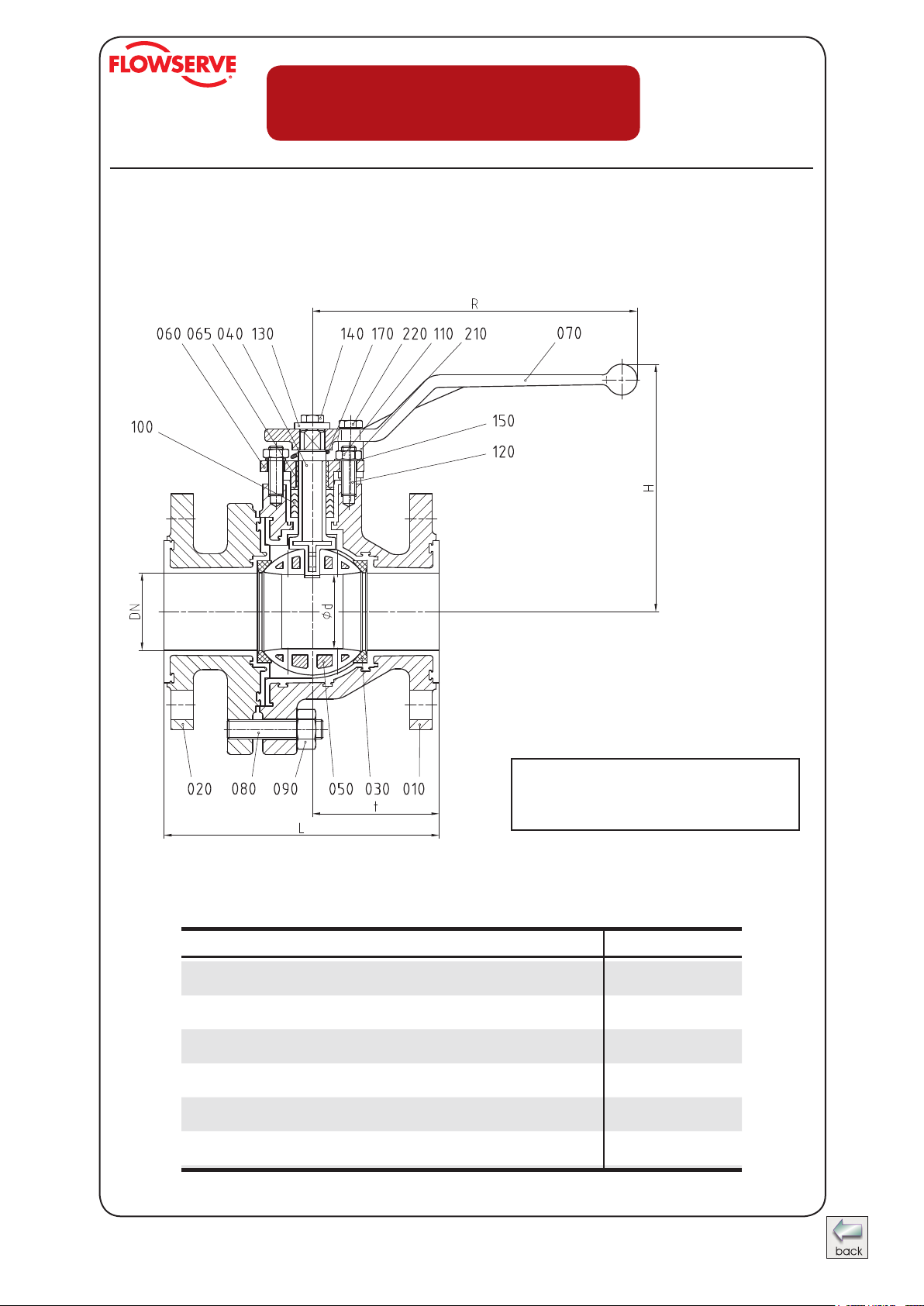
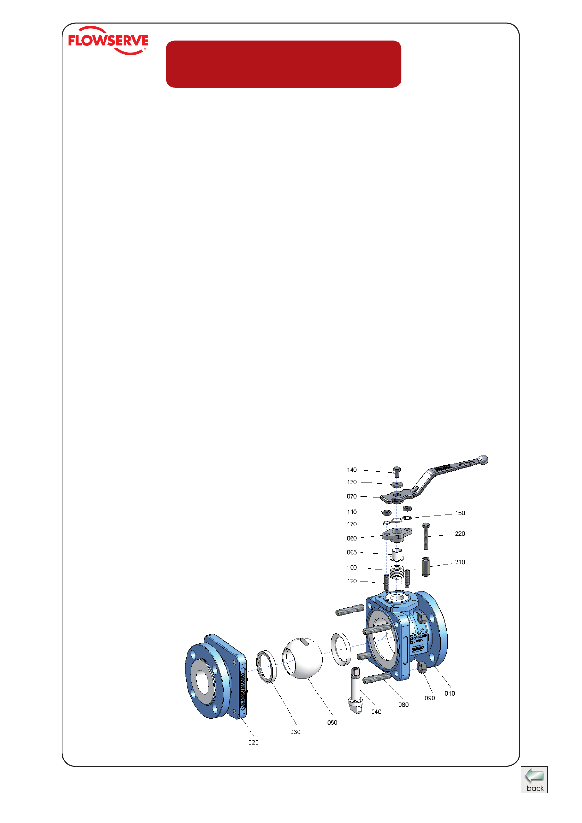
Material specication AKH2A
No. Designation Pieces Material Material-No. / DIN ASTM / AISI
010 body 1 ductile iron / FEP ° EN-JS1049 (GGG-40.3) / A 395
020 side piece 1 ductile iron / FEP ° EN-JS1049 (GGG-40.3) / A 395
030 seat ring 2 PTFE pure - PTFE
040 stem 1 stainless steel / PFA 1.4470 /DIN EN 10283 A 890 CD3MN
050 ball
060 gland follower 1 stainless steel 1.4308 / DIN EN 10283 A 743 CF-8
065 gland insert 1 PTFE-graphite
070 hand lever
080 stud bolt 1 set stainless steel 1.4301-K70 / DIN EN 10088-3 A 193 B8
090 hexagon nut 1 set stainless steel 1.4301-K70 / DIN EN 10088-3 A 194 8
100 packing material 1 set PTFE °
110 hexagon nut 2 stainless steel 1.4301 / DIN EN 10088-3 A 194 8
120 stud bolt 2 stainless steel 1.4301 / DIN EN 10088-3 A 193 B8
130 lock washer 1 stainless steel 1.4301 / DIN EN 10088-3 AISI 304
140 hexagon bolt 1 stainless steel 1.4301 / DIN EN 10088-3 A 193 B8
150 serrated lock washer 1 stainless steel 1.4301 / DIN EN 10088-3 AISI 304
170 grounding device 1 stainless steel 1.4310 / DIN EN 10270-3 AISI 301
210 stop
220 hexagon bolt** 1 stainless steel 1.4301 / DIN EN 10088-3 A 193 B8
DN 1“ - 2“ 1 tool steel, alloyed / PFA° 1.2343 / DIN EN ISO 4957 A 646-95 (Gr. 10)
DN 3“ - 6“ 1 ductile iron / FEP ° EN-JS1049 (GGG-40.3) / A 395
DN 1“ - 2“ 1 die cast metall ZP0410 / DIN EN 12844
DN 3“ - 4“ 1 malleable cast iron (galvanizing) EN-GJS-50-7 (GGG-50)
DN 6“: adapter;
level
(chevron) PTFE-graphite °
DN 1“ - 4“ 1 steel (galvanizing) 1.0037 / DIN EN 10025-2 A 283 B
DN 6“ 1 stainless steel 1.4104 / DIN EN 10088-3 AISI 430 F
1
ductile iron / PFA ° DIN EN 1563
ductile iron / PFA ° DIN EN 1563
Hastelloy C4 / PFA °° 2.4610 / DIN 17744
tool steel, alloyed / FEP°
ductile iron / PFA ° DIN EN 1563
ceramic Al
stainless steel;
steel (chromated)
2O3
*
1.4308 / DIN EN 10283;
1.0037 / DIN EN 10025-2
A 743 CF-8
A283 B
* ceramic ball on request
°° Hastelloy stem on request
° optional
** DN 6“ 2 hexagon bolts
AKH2A - atomac ball valve
Page 4
Ahaus GmbH
von-Braun-Straße 19a
D-48683 Ahaus
Postfach 1162 D-48661 Ahaus
Telefon: +49(0) 2561-686-100
Fax: +49(0) 2561-686-200
Technical Manual
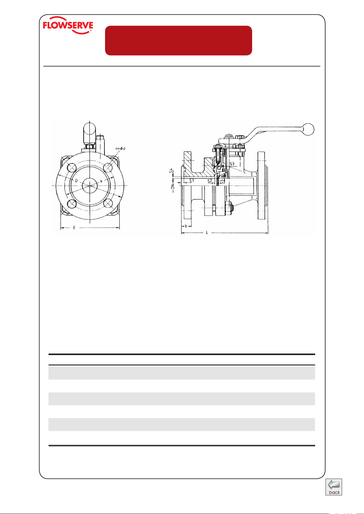
Dimensions AKH2A
Register: 13
Page: 4
Date: 12.1995
Revision: 08.2009
DN / ANSI L E ° b D k nxØd S1 S2 S3 S4 S5
inch 5 3,82 0,57 4,25 3,13 4x0,63 0,16 0,1 0,13 0,13 0,1
1“
mm 127 97 14,5 107,9 79,2 4x16 4,0 2,5 3 3 2,5
inch 6,5 4,65 0,71 5 3,88 4x0,63 0,16 0,13 0,13 0,13 0,13
1½“
mm 165 118 18 127 98,5 4x16 4 3 3 3 3
inch 7 5,51 0,75 6 4,75 4x0,75 0,16 0,13 0,13 0,13 0,13
2“
mm 178 140 19 152,4 120,5 4x19 4 3 3,0 3 3
inch 8 8,66 0,85 7,5 6 4x0,75 0,16 0,14 0,16 0,14 0,16
3“
mm 203 220 21,5 190,5 152,5 4x19 4 3,5 4 3,5 4
inch 9 9,65 1,02 9 7,5 8x0,75 0,16 0,14 0,16 0,14 0,16
4“
mm 229 245 26 228,6 190,5 8x19 4 3,5 4 3,5 4
inch 10,5 12,32 1,14 11 9,5 8x0,87 0,16 0,2 0,16 0,2 0,12
6“
mm 267 313 29 279,4 241,5 8x22 4 5 4 5 4,5
stem lining DN 1“ 0,059 inch
all other sizes at least 0,098 inch
° DN 3“ and 4“ hexagonal
° DN 6“ octagonal
AKH2A - atomac ball valve
Page 5
Register: 13
Ahaus GmbH
von-Braun-Straße 19a
D-48683 Ahaus
Postfach 1162 D-48661 Ahaus
Telefon: +49(0) 2561-686-100
Fax: +49(0) 2561-686-200
Technical Manual
Page: 5
Date: 12.1995
Revision: 08.2009
Spare Parts (item n°) - AKH2A Standard Version
ANSI
1“ 0000268 0000323 0002317 0000159
1½“ 0000270 0000325 0002319 0000160
2“ 0000271 0000326 0002320 0000161
3“ 0009170 0009172 -- 0009425
4“ 0009171 0009173 -- 0009426
6“ 0009340 0009341 -- 0009427
ANSI
1“ 0000115 0000116 0000167 0000174
1½“ 0000117 0000118 0000168 0000175
2“ 0000119 0000120 0000169 0000176
3“ 0000121 0000122 0000170 0000177
4“ 0000121 0000122 0000170 0000177
6“ 0000123 0000124 0000172 0000179
° Al
2O3
FEP PFA PTFE
Stem
Stainless Steel / PFA
Hastelloy / PFA PTFE
Ball
Ceramic°
Packing (set)
Seat Rings
PTFE / Graphite
AKH2A - atomac ball valve
Page 6

Register: 13
Ahaus GmbH
von-Braun-Straße 19a
D-48683 Ahaus
Postfach 1162 D-48661 Ahaus
Telefon: +49(0) 2561-686-100
Fax: +49(0) 2561-686-200
Technical Manual
Page: 6
Date: 12.1995
Revision: 08.2009
Assembly Instructions AKH2A
The general installation and maintenance instructions must be observed.
1. Screw stud bolts (120) into body (010).
2. Insert stem (040) from inside of body in such a way that the at side is parallel to
body longitudinal axis.
3. Insert chevron packing (100).
4. Install gland insert (065), gland follower (060), safety washers (150), hexagon nuts
(110) and grounding strap (170) also on valves with actuator.
5. Install hand lever (070) on to stem (040) and tighten it using lock washer (130) and
hexagon bolt (140).
6. Insert rst ball seat ring (030) into body (010).
7. Insert ball (050) to valve stem by pushing the ball in a downward motion through
valve body.
8. Turn hand lever 90° of longitudinal axis of body.
9. Install second ball seat ring (030) on to ball (050).
10. Install side piece (020) on to body (010).
11. Install body bolts (080) and hexagon nuts (090) and tighten by crisscross method to
recommended torques.
12. Assemble stop (210) with hexagon bolt (220).
AKH2A - atomac ball valve
DN 1“ to 2“ = quadrangular Flange
DN 3“ and 4“ = sexangular Flange
Page 7
Register: 13
Ahaus GmbH
von-Braun-Straße 19a
D-48683 Ahaus
Postfach 1162 D-48661 Ahaus
Telefon: +49(0) 2561-686-100
Fax: +49(0) 2561-686-200
Technical Manual
Page: 7
Date: 12.1995
Revision: 08.2009
Disassembly Instructions for AKH2A
For all jobs which are to be carried out on an installed valve, the works safety requirements and the general accident prevention instructions must be observed. Moreover,
the general installation and maintenance instructions for atomac uorcarbon resin lined
valves must be considered.
1. Prior to disassembly, the valve must be cleared of all uid according to the above-
mentioned instructions. Particular care must be taken that during rinsing and draining of the piping, the valve is opened and closed repeatedly. These cycles (opening
and closing) are to be repeated during draining of the piping. Only when following
this procedure, is it ensured that all remaining pressure inside the body (stem guide
and ball seats) is eliminated.
2. For disassembly of the valve, put body on a work bench with a soft cover (rubber
mat). Remove hexagon bolt (110) and serrated lock washer (150).
3. Open valve completely. Remove hand lever (070).
4. Disassemble grounding device (170).
5. Disassemble gland follower (060) and gland insert (065). If necessary, stud bolts
(120) can also be removed now.
6. Remove body bolts (080) and separate side piece from body.
7. Remove rst ball seat ring (030).
8. Put ball in closed position and push ball out of the body.
9. Remove stem (040) by pushing it down through
the body (010). Care must be taken not to
damage body liner.
10. Chevron packing (100) can easily be removed.
11. If necessary, remove hand lever stop
(210) by releasing bolt (220).
DN 1“ to 2“ = quadrangular Flange
DN 3“ and 4“ = sexangular Flange
AKH2A - atomac ball valve
Page 8
Ahaus GmbH
von-Braun-Straße 19a
D-48683 Ahaus
Postfach 1162 D-48661 Ahaus
Telefon: +49(0) 2561-686-100
Fax: +49(0) 2561-686-200
AKH2A - recommended tightening torques*
Technical Manual
Register: 13
Page: 8
Date: 12.1995
Revision: 08.2009
tie rods gland bolts
DN
1“ 19 168 15 133 4 35
1½“ 38 336 26 230 7 62
2“ 66 584 60 531 7 62
3“ 116 1027 100 885 8 71
4“ 140 1239 76 673 8 71
6“ 161 1425 129 1142 12 106
* maximum value
(080/090) (110/120/150)
Nm in.lbs Nm in.lbs Nm in.lbs
connection ange
AKH2A - atomac ball valve
Page 9

Register: 13
Ahaus GmbH
von-Braun-Straße 19a
D-48683 Ahaus
Postfach 1162 D-48661 Ahaus
Telefon: +49(0) 2561-686-100
Fax: +49(0) 2561-686-200
Technical Manual
Page: 9
Date: 12.1995
Revision: 08.2009
Manual Actuator
(worm gear)
The fully closed, waterproof actuator consists of a body with lid, worm gear, input
shaft and hand wheel. For the correct adjustment of the ball position, there are two
adjustable stops mounted in the body.
The gear is fully greased and does not need any further lubrication.
The actuator with hand wheel is mounted on a bracket with four stainless steel bolts.
The on/off position is indicated through a pointer. The actuator is self-locked.
Material specication
Designation Material Material-No. DIN
body GG-25 0.6025 DIN EN 1561
worm EN-HJS-400-15U EN-JS1072 DIN 18299
(GGG-40) (0.7040)
gear EN-HJS-400-15U EN-JS1072 DIN 18299
(GGG-40) (0.7040)
grease special high temp. grease (up to 120°C)
input shaft AISI 303 1.4305
hand wheel malleable cast iron
AKH2A - atomac ball valve
Page 10

Ahaus GmbH
von-Braun-Straße 19a
D-48683 Ahaus
Postfach 1162 D-48661 Ahaus
Telefon: +49(0) 2561-686-100
Fax: +49(0) 2561-686-200
Register: 13
Page: 10
Technical Manual
Date: 12.1995
Revision: 08.2009
Material specication - AKH2A with
manual actuator
No. Designation Pieces Material Material-No. DIN ASTM / AISI
010 actuator 1 steel 1.0037 DIN EN 10025-2 A 283 B
020 hexagon bolt 4 stainless steel 1.4301 DIN EN 10088-3 A 193 B8
030 serrated lock washer 4 stainless steel 1.4301 DIN EN 10088-3 AISI 304
040 adapter 1 stainless steel 1.4104 DIN EN 10088-3 AISI 430 F
050 actuator 1
060 hexagon bolt 4 stainless steel 1.4301 DIN EN 10088-3 A 193 B8
070 key 1 steel 1.0050 DIN EN 10277-1 A 572 GR 50
AKH2A - atomac ball valve
Page 11

Ahaus GmbH
von-Braun-Straße 19a
D-48683 Ahaus
Postfach 1162 D-48661 Ahaus
Telefon: +49(0) 2561-686-100
Fax: +49(0) 2561-686-200
Technical Data - AKH2A with manual actuator
Technical Manual
Register: 13
Page: 11
Date: 12.1995
Revision: 08.2009
Dimensions acc. to DIN EN ISO 5211
ANSI TYP* A B C D ØE F ØG K
4“
6“
* with standard hand wheel
Q 400 S 44 : 1 400 3540 3,87
Q 800 S 40 : 1 800 7081 7,68
mm
Q 400 S
inch 11,53 5,43 3,15 1,34 7,87 8,39 0,47 2,07
mm
Q 800 S
inch 14,23 7,52 3,15 1,67 11,81 11,14 0,59 2,71
Typ gear transmission ratio touque in Nm touque in lbs weight in kg
293 138 80 34 200 213 12 52,5
362 191 80 42,5 300 283 15 68,8
AKH2A - atomac ball valve
Page 12

Ahaus GmbH
von-Braun-Straße 19a
D-48683 Ahaus
Postfach 1162 D-48661 Ahaus
Telefon: +49(0) 2561-686-100
Fax: +49(0) 2561-686-200
Technical Manual
AKH2A with actuator mounting
Register: 13
Page: 13
Date: 12.1995
Revision: 08.2009
AKH2A - atomac ball valve
Page 13

Register: 13
Ahaus GmbH
von-Braun-Straße 19a
D-48683 Ahaus
Postfach 1162 D-48661 Ahaus
Telefon: +49(0) 2561-686-100
Fax: +49(0) 2561-686-200
Technical Manual
Page: 14
Date: 12.1995
Revision: 08.2009
Material specication - AKH2A with
actuator mounting
No. Designation Pieces Material Material-No. DIN ASTM / AISI
010 threaded pin 1 stainless steel 1.4301 DIN EN 10088-3 A 193 B8
020 actuator bracket 1 steel (yellow chromated) 1.0037 DIN EN 10025-2 A 283-B
030 serrated lock washer 4 stainless steel 1.4301 DIN EN 10088-3 AISI 304
040 hexagon bolt 4 stainless steel 1.4301 DIN EN 10088-3 A 193 B8
050 adapter 1 stainless steel 1.4304 DIN EN 10088-3 AISI 304F
Item-No. 010 „threaded pin“ is used with sizes DN 1“.
AKH2A - atomac ball valve
Page 14

Register: 13
Ahaus GmbH
von-Braun-Straße 19a
D-48683 Ahaus
Postfach 1162 D-48661 Ahaus
Telefon: +49(0) 2561-686-100
Fax: +49(0) 2561-686-200
Technical Manual
Page: 15
Date: 12.1995
Revision: 08.2009
AKH2A - Dimension sheet for actuator mounting
acc. to NAMUR - recommendation
Dimensions acc. to DIN EN ISO 5211
with metric ISO-Threads DIN 13-1
+0,1 0
ANSI
mm 109 75 60 100 8 10 - 30,5 9,3
1“
inch 4,29 2,95 2,36 3,94 0,315 0,393 - 1,2 0,37
mm 129 100 60 100 12 16 - 25,5 12,5
1½“
inch 5,08 3,94 2,36 3,94 0,472 0,63 - 1 0,49
mm 142 100 60 100 12 16 - 23 12,5
2“
inch 5,59 3,94 2,36 3,94 0,472 0,63 - 0,91 0,49
mm 203 135 80 140 16 22 13 34 15,5
3“
inch 8 5,31 3,15 5,51 0,63 0,866 0,51 1,34 0,61
mm 218 135 80 140 16 22 13 34 15,5
4“
inch 8,58 5,31 3,15 5,51 0,63 0,866 0,51 1,34 0,61
mm 271 135 80 140 20 30 14 23 19,5
6“
inch 10,67 5,31 3,15 5,51 0,787 1,181 0,55 0,91 0,77
H a b c SW d S L1 L2
AKH2A - atomac ball valve
-0,1 -0,1
DIN EN ISO
5211
ISO 5211
F05
F07
F07
F10
F10
F12
Page 15

Register: 13
Ahaus GmbH
von-Braun-Straße 19a
D-48683 Ahaus
Postfach 1162 D-48661 Ahaus
Telefon: +49(0) 2561-686-100
Fax: +49(0) 2561-686-200
Technical Manual
Page: 16
Date: 12.1995
Revision: 08.2009
AKH2A/DA
Seat ring with pressure compensation grooves
Nut a < DN 1“ = 1,5 mm
Nut a < DN 3“ = 2,0 mm
Nut a > DN 3“ = 3,0 mm
Special Recleaning and Packing Procedures
1. R e c l e a n i n g
The ball valve should be thouroughly cleaned with a clean, dry, lint-free towel and
blown off with dry nitrogen gas. This will assure that the valve is free from moisture,
grease and other media before packing.
2. P a c k i n g
Prior to packing, the ball valve should be jig welded in a PE-foil (0,2 mm thick). The
bag contains desiccants acc. to DIN 55473, quantity acc. to DIN 555474 and a
moisture indicator.
AKH2A - atomac ball valve
Page 16

Register: 13
Ahaus GmbH
von-Braun-Straße 19a
D-48683 Ahaus
Postfach 1162 D-48661 Ahaus
Telefon: +49(0) 2561-686-100
Fax: +49(0) 2561-686-200
Technical Manual
Page: 17
Date: 12.1995
Revision: 08.2009
Material specication AKH2A/DA
No. Designation Pieces Material Material-No. / DIN ASTM / AISI
010 body 1 ductile iron / FEP ° EN-JS1049 (GGG-40.3) / A 395
020 side piese 1 ductile iron / FEP ° EN-JS1049 (GGG-40.3) / A 395
030 seat ring 1 PTFE pure - PTFE
035 seat ring with pressure
compensation grooves
040 stem 1 stainless steel / PFA 1.4470 /DIN EN 10283 A 890 CD3MN
050 ball
060 gland follower 1 stainless steel 1.4308 / DIN EN 10283 A 743 CF-8
065 gland insert 1 PTFE-graphite
070 hand lever
080 stud bolt 1 set stainless steel 1.4301-K70 / DIN EN 10088-3 A 193 B7
090 hexagon nut 1 set stainless steel 1.4301-K70 / DIN EN 10088-3 A 194 2H
100 packing material 1 set PTFE °
110 hexagon nut 2 stainless steel 1.4301 / DIN EN 10088-3 A 194 8
120 stud bolt 2 stainless steel 1.4301 / DIN EN 10088-3 A 193 B8
130 lock washer 1 stainless steel 1.4301 / DIN EN 10088-3 AISI 304
140 hexagon bolt 1 stainless steel 1.4301 / DIN EN 10088-3 A 193 B8
150 serrated lock washer 2 stainless steel 1.4301 / DIN EN 10088-3 AISI 304
170 grounding device 1 stainless steel 1.4310 / DIN EN 10270-3 AISI 301
210 stop
220 hexagon bolt** 1 stainless steel 1.4301 / DIN EN 10088-3 A 193 B8
DN 1“ - 2“ 1 tool steel, alloyed / PFA° 1.2343 / DIN EN ISO 4957 A 646-95 (Gr. 10)
DN 3“ - 6“ 1 ductile iron / FEP ° EN-JS1049 (GGG-40.3) / A 395
DN 1“ - 2“ 1 die cast metall ZP0410 / DIN EN 12844
DN 3“ - 4“ 1 malleable cast iron (galvanizing) EN-GJS-50-7 (GGG-50)
DN 6“: adapter;
level
(chevron) PTFE-graphite °
DN 1“ - 4“ 1 steel (galvanizing) 1.0037 / DIN EN 10025-2 A 283 B
DN 6“ 1 stainless steel 1.4104 / DIN EN 10088-3 AISI 430 F
ductile iron / PFA ° DIN EN 1563
ductile iron / PFA ° DIN EN 1563
1 PTFE pure - PTFE
Hastelloy C4 / PFA °° 2.4610 / DIN 17744
tool steel, alloyed / FEP°
ductile iron / PFA ° DIN EN 1563
ceramic Al
stainless steel;
1
steel (chromated)
2O3
*
1.4308 / DIN EN 10283; 1.0037 /
DIN EN 10025-2
A 743 CF-8
A283 B
* ceramic ball on request
°° Hastelloy stem on request
° optional
** DN 6“ 2 hexagon bolts
AKH2A - atomac ball valve
Page 17

Register: 13
Ahaus GmbH
von-Braun-Straße 19a
D-48683 Ahaus
Postfach 1162 D-48661 Ahaus
Telefon: +49(0) 2561-686-100
Fax: +49(0) 2561-686-200
Technical Manual
Page: 18
Date: 12.1995
Revision: 08.2009
Assembly Instructions AKH2A/DA
The general installation and maintenance instructions must be observed.
Attention, please take care of the right direction of the indicator while assembly.
1. Screw stud bolts (120) into body (010).
2. Insert stem (040) from inside of body in such a way that the at side is paral-
lel to body longitudinal axis.
3. Insert chevron packing (100).
4. Install gland insert (065), gland follower (060), safety washers (150),
hexagon nuts (110) and grounding strap (170) also on valves with actuator.
5. Install hand lever (070) on to stem (040) and tighten it using lock washer
(130) and hexagon bolt (140).
6. Insert rst ball seat ring (030) into body (010).
7. Insert ball (050) to valve stem by pushing the ball in a downward motion
through valve body.
8. Turn hand lever 90° of longitudinal axis of body.
9. Install ball seat ring with pressure compensation grooves (035) on to ball (050).
10. Install side piece (020) on to body (010).
11. Install body bolts (080) and hexagon nuts
(090) and tighten by crisscross
method to recommended torques.
12. Assemble stop (210) with
hexagon bolt (220).
Disassembly instruction see register 13,
page 7
AKH2A - atomac ball valve
Page 18

Ahaus GmbH
von-Braun-Straße 19a
D-48683 Ahaus
Postfach 1162 D-48661 Ahaus
Telefon: +49(0) 2561-686-100
Fax: +49(0) 2561-686-200
Technical Manual
AKH2A with stem extension
Register: 13
Page: 19
Date: 12.1995
Revision: 08.2009
AKH2A - atomac ball valve
Page 19

Register: 13
Ahaus GmbH
von-Braun-Straße 19a
D-48683 Ahaus
Postfach 1162 D-48661 Ahaus
Telefon: +49(0) 2561-686-100
Fax: +49(0) 2561-686-200
Technical Manual
Page: 20
Date: 12.1995
Revision: 08.2009
Material specication - AKH2A with stem extension
No. Designation Pieces Material Material-No. DIN ASTM / AISI
010 threaded pin 1 stainless steel 1.4301 DIN EN 10088-3 A 193 B8
020 stud bolt 2 stainless steel 1.4301 DIN EN 10088-3 A 193 B8
030 gland follower 1 stainless steel / PTFE-graphite 1.4308 DIN EN 10283 A 351 CF 8
040 distance pipe 1 steel 1.0305 DIN EN 10216-2 A 192
050 gland 1 stainless steel 1.4308 DIN EN 10283 A 743 CF 8
060 serrated lock washer 2 stainless steel 1.4301 DIN EN 10088-3 AISI 304
070 hexagon nut 2 stainless steel 1.4301 DIN EN 10088-3 A 194 8
080 extended stem 1 stainless steel 1.4104 DIN EN 10088-3 AISI 430 F
090 mounting 1 steel 1.0037 DIN EN 10025-2 A 283 B
100 serrated lock washer 4 stainless steel 1.4301 DIN EN 10088-3 AISI 304
110 hexagon bolt 4 stainless steel 1.4301 DIN EN 10088-3 A 193 B8
Item - No. 010 „threaded pin“ is used with sized DN 1“ only.
AKH2A - atomac ball valve
Page 20

Ahaus GmbH
von-Braun-Straße 19a
D-48683 Ahaus
Postfach 1162 D-48661 Ahaus
Telefon: +49(0) 2561-686-100
Fax: +49(0) 2561-686-200
Technical Data - AKH2A with stem extension
Technical Manual
Register: 13
Page: 21
Date: 12.1995
Revision: 08.2009
ANSI L H h
1“
1½“
2“
3“
4“
6“
mm 100 149 126
inch 3,94 5,87 4,96
mm 100 169 138
inch 3,94 6,65 5,43
mm 100 182 151
inch 3,94 7,17 5,94
mm 130 252 216
inch 5,12 9,92 8,5
mm 130 267 231
inch 5,12 10,51 9,09
mm 160 351 307
inch 6,3 13,82 12,09
AKH2A - atomac ball valve
Page 21

Register: 13
Ahaus GmbH
von-Braun-Straße 19a
D-48683 Ahaus
Postfach 1162 D-48661 Ahaus
Telefon: +49(0) 2561-686-100
Fax: +49(0) 2561-686-200
Technical Manual
Page: 22
Date: 12.1995
Revision: 08.2009
Technical Data - AKH2A with lockable hand lever
A
A ( 1 : 2 )A ( 1 : 2 )
Material specication - AKH2A with lockable hand lever
Designation Pieces Material Material-No. DIN ASTM / AISI
lockable hand lever 1 stainless steel 1.4301 DIN EN 10088-3 AISI 304
stop bolt 1 Stainles steel / duroplastic 1.4301 DIN EN 10088-3 AISI 304
AKH2A - atomac ball valve
Page 22

Ahaus GmbH
von-Braun-Straße 19a
D-48683 Ahaus
Postfach 1162 D-48661 Ahaus
Telefon: +49(0) 2561-686-100
Fax: +49(0) 2561-686-200
Technical Manual
AKH2A - Kv DATA and Cv Data
(DIN EN 60534-2-3)
Register: 13
Page: 23
Date: 12.1995
Revision: 08.2009
K
ANSI
1“ 46,6 54,1
1 ½“ 126,9 147,5
2“ 202,5 235,4
3“ 507,8 590,2
4“ 953,4 1108,1
6“ 1577,7 1833,8
V
m³/h gal/min
C
V
AKH2A - atomac ball valve
Page 23

Ahaus GmbH
von-Braun-Straße 19a
D-48683 Ahaus
Postfach 1162 D-48661 Ahaus
Telefon: +49(0) 2561-686-100
Fax: +49(0) 2561-686-200
Technical Manual
Optional C-ball in ball valves
Register: 13
Page: 24
Date: 12.1995
Revision: 08.2009
For details please contact ouer Sales ofce at Ahaus, Germany
AKH2A - atomac ball valve
Page 24

Ahaus GmbH
von-Braun-Straße 19a
D-48683 Ahaus
Postfach 1162 D-48661 Ahaus
Telefon: +49(0) 2561-686-100
Fax: +49(0) 2561-686-200
Technical Manual
Optional V-ball in ball valves
Register: 13
Page: 25
Date: 12.1995
Revision: 08.2009
For details please contact ouer Sales ofce at Ahaus, Germany
AKH2A - atomac ball valve
 Loading...