

Page 1
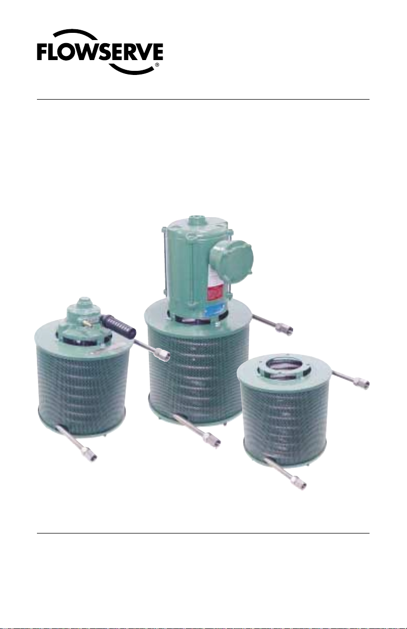
Airfin Cooler
Flow Solutions Division
Durametallic Seals
Means of reducing
the temperatures
surrounding a
mechanical seal
Model 625 FC Air Motor
Code: WCA26748333
Installation Instructions
Model 625 FC Electric Motor
3 phase Code: WCA14020233
1 phase Code: WCA18856933
Model 625 NC
Code: WCA14640733
Page 2
Description
The Airfin Cooler provides a reliable means of reducing the temperature surrounding a mechanical seal, without the use of cooling water.
There are three models of Airfin Coolers. The Model 625 NC operates by means
of natural convection. Hot air rises up through the center of the coiled tubing,
drawing cool air in from the sides and bottom. The two Model 625 FC units are
identical to the above model, except they are equipped with motor driven squirrel
cage type blower wheels.
1 Installation
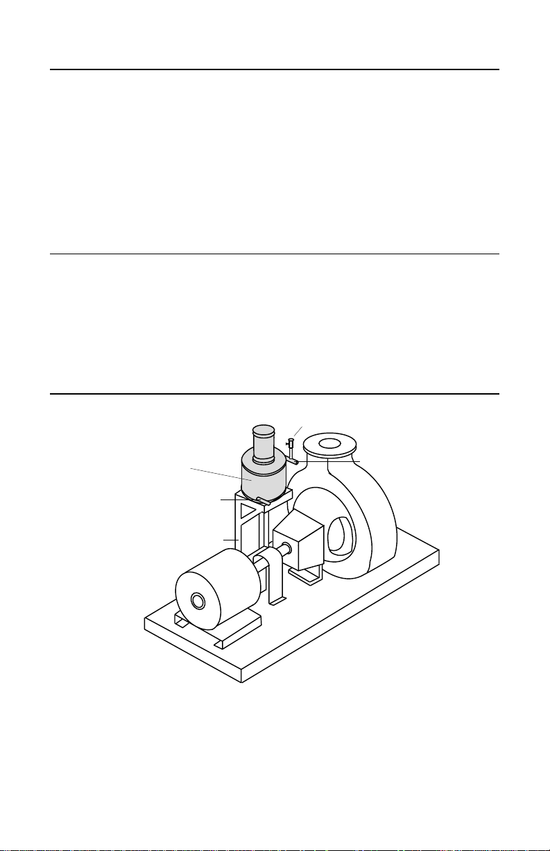
1.1 All models must be mounted in a vertical position, adjacent to and above
the seal chamber. The piping, or tubing, to and from the Airfin Cooler
should be as short as possible. See Figure 1.
Typical Installation of Airfin Cooler Figure 1
Airfin Cooler
• 6-12" Above
seal chamber
• No more than 4'
from seal chamber
Cooled Product Outlet
Mounting
Bracket
Vent Valve
Hot Product Inlet
1.2 The Airfin Cooler should be mounted in a location where it will be free from
all obstructions on the top, bottom, and sides. Failure to do so will result in
an appreciable reduction in heat transfer efficiency.
1.3 Please read the complete instructions before starting installation. Be sure
you have a copy of the proper Airfin Cooler assembly drawing.
© Copyright 2003 Flowserve Corporation
2
Page 3

1.4 Select the proper location. It will be necessary to fabricate or purchase a
mounting bracket to suit your particular installation. See Figure 2 for
recommended mounting bracket dimensions. The Airfin Cooler should be
located 6-12” above and no more than 4’ from the seal chamber.
Mounting Bracket Details Figure 2
9.00" Min.
9.00" Min.
10.50"
5.25"
5.25"
10.50"
4 - .437” Dia. holes
as shown
1.5 Carefully place the Airfin Cooler on the mounting bracket. The Airfin Cooler
should be positioned so that the least amount of elbows or tube bends are
needed for the inlet and outlet piping.
Note: If the inlet and outlet fittings are not in the desired positions, the coil
assembly can be rotated 360° to any desired position. Loosen the four hex
head bolts (Part No. 10 of Model 625 FC and Part No. 5 of Model 625 NC)
and rotate the cooling coil/shroud assembly to the desired position. Be sure
to tighten the four hex head bolts securely.
1.6 After the unit has been placed on the mounting bracket in the desired
position, secure it down with four hex nuts (3/8” - 16 UNC-2B) with lock
washers.
1.7 Consult your assembly drawing for the connections size and location. The
hot product line to the Airfin Cooler should be piped to the top of the unit
and the cooled product outlet line should be piped from the bottom of the
unit. Connect the inlet and outlet lines with suitable piping or tubing.
1.8 Be sure to install a vent value in the hot product inlet line. The vent valve
should be located at he highest point in the piping.
1.9 The Model 625 FC Airfin Cooler has a 1/3 HP motor. Consult the assembly
drawing for your motor specifications.
3
Page 4

TO REORDER REFER TO
B/M #
.
F.O
2 Operation
2.1 Inspect the Airfin Cooler to insure that the cooling coil has not been
painted, sprayed with oil, or covered with dirt or dust. Insure that there are
no obstructions on the top, bottom, and sides.
2.2 Apply power momentarily to the motor on the Model 625 FC to check for
rotation. If the rotation is in the wrong direction, rewire the motor.
2.3 Open the pump suction valve and fill the system with product. Crack the
vent valve in the hot product line and vent all air from the system.
2.4 Check all fittings for leaks and make required adjustments. Do not tighten
fittings excessively.
2.5 Apply power to the motor on the Model 625 FC and start the pump, for the
625 NC model start the pump.
Maintenance
The Airfin Cooler is relatively maintenance free. To insure maximum heat transfer
efficiency, keep the cooling coils dry and free of dirt and dust. Periodically, clean
the cooling coil by blowing air or steam through the protective shroud.
All Flowserve Corporation, Flow Solutions Division, products must be installed in accordance with Flowserve
installation instructions. Failing to do so or attempting to change or modify Flowserve products will void Flowserve’s
limited warranty. Flowserve’s limited warranty is described fully in Flowserve’ s Standard Terms and Conditions
of Sale. Flowserve makes no warranty of merchantability or fitness for a particular purpose and in no event shall
Flowserve be liable for consequential or incidental damages.
Flowserve Corporation Flow Solutions Division
Primary Worldwide Flow Solutions Division Locations Licensees, authorized agents, and affiliated companies located worldwide
United States
Kalamazoo, MI
Phone 269-381-2650
Fax 269-382-8726
Singapore Japan
Phone 65-6-8465100
Fax 65-6-747-1963
Printed in U.S.A.
Edmonton, Alberta
Phone 780-463-7958
Fax 780-450-1241
Tlaxcala
Phone 52-2-461-6791
Fax 52-2-461-6847
Canada
Scarborough, Ontario
Phone 416-292-2877
Fax 416-292-5190
Sao Paulo
Phone 55-11-4066-8600
Fax 55-11-4066-7014
Netherlands
Roosendaal
Phone 31-165-581400
Fax 31-165-552622
Osaka
Phone 81-720-85-5571
Fax 81-720-85-5575
ISO 9000
Certified
Argentina
Villa Martelli
Phone 54-11-4709-6800
Fax 54-11-4709-7072
GermanyBrazilMexico
Dortmund
Phone 49-231-6964-0
Fax 49-231-6964-248
Australia
Marayong NSW
Phone 61-2-8822-7100
Fax 61-2-9679-7511
FIS154
REV 02/03 USA
 Loading...