

Page 1
Worcester Controls
FCD WCABR1011-00
(Part PB 451)
AN ISO 9001 REGISTERED COMPANY
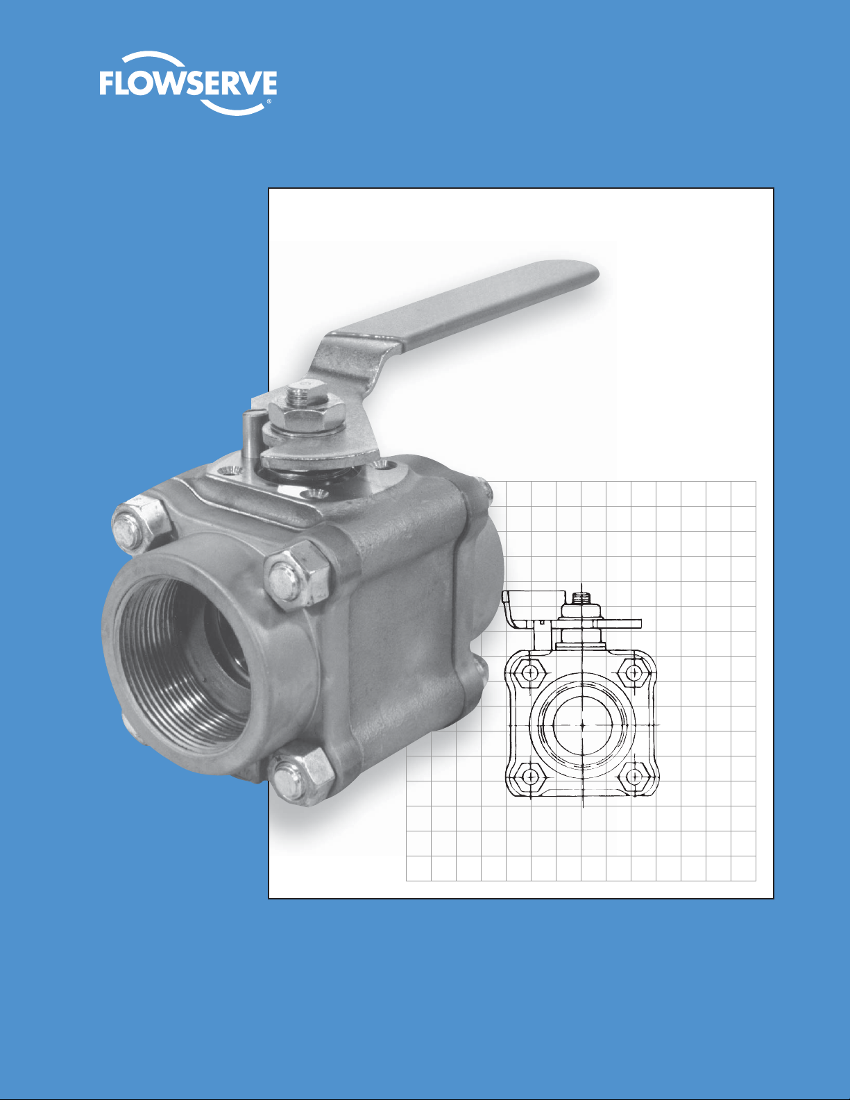
Series 59 Full-Port Ball Valve
Full-port valves offer maximum capacity,
minimum restriction, optional fi re-rated design
Page 2
Series 59 Full-Port Ball Valves
Manual and automated valves for processes requiring maximum fl ow area
Flow Control Division
Worcester Controls
Full-port ball valves are recommended for processes requiring
minimum restriction through piping, shutoff valves, and other
equipment. For example, pump inlet valves are often full-port
valves. Full-port valves are also useful in systems handling
slurries, viscous fl uids and fl uids with residues, and where the
capacity to pig lines is desired.
¼ "- 2" Series 59 valves are rated to ANSI Class 600. 3" and 4"
valves are rated to ANSI Class 300.
Worcester offers a complete line of pneumatic and electric
automation packages for on/off or throttling control, including
the Series 39 twin piston pneumatic actuator and the Series 75
electric actuator.
Series 59 full-port valves are available in a fi re-rated confi guration
AF59 in sizes ½ ", ¾ ", 1", 1½ ", and 2". Flanged ANSI Class 150 and
300 full-port valves are available in sizes ½ "- 10".
Specifi cations
Sizes: ¼ ", 3⁄8", ½ ", ¾ ", 1", 1¼ ", 1½ ", 2", 3", 4"
Style: Three-piece, four-bolt (¼ "- 2")
Three-piece, eight-bolt (3"- 4")
Valve ¼ " - 2" Carbon Steel and Stainless Steel Valves,
Pressure ANSI Class 600
Rating*: 3"- 4" Carbon Steel and Stainless Steel Valves,
ANSI Class 300
¼ "- 1" Brass Valves, 1500 psi
1¼ "- 1½ " Brass Valves, 1000 psi
Body: Carbon Steel, 316 Stainless Steel,
Brass (valve sizes ¼ "- 1½ ")
Pipe Ends: Screw End, Socket Weld, Butt Weld, Tube End
Ball: Chrome Plated Brass
316 Stainless Steel
Temp. Range: Depends on seat and seal choice;
will operate from -20°F to +600°F
Seat/Seal Standard valves, less than 1 x 10⁻⁶ cc He/sec
Leakage: inboard and through (bubbletight is 1 x 10⁻⁴ cc
He/sec). With preparation, leakage will be less
than 2 x 10
to bubbletight standards.
Flow: Bidirectional
* These are valve body pressure ratings. Seat selection may derate the valve.
Example: a 1" carbon steel Series 59 valve has a rating of 1480 psi at 70°F.
Selection of reinforced TFE seats operating at fl uid temperature of 200°F limits
allowable pressure in the valve to 1000 psi.
-9
cc He/sec. All valves 100% tested
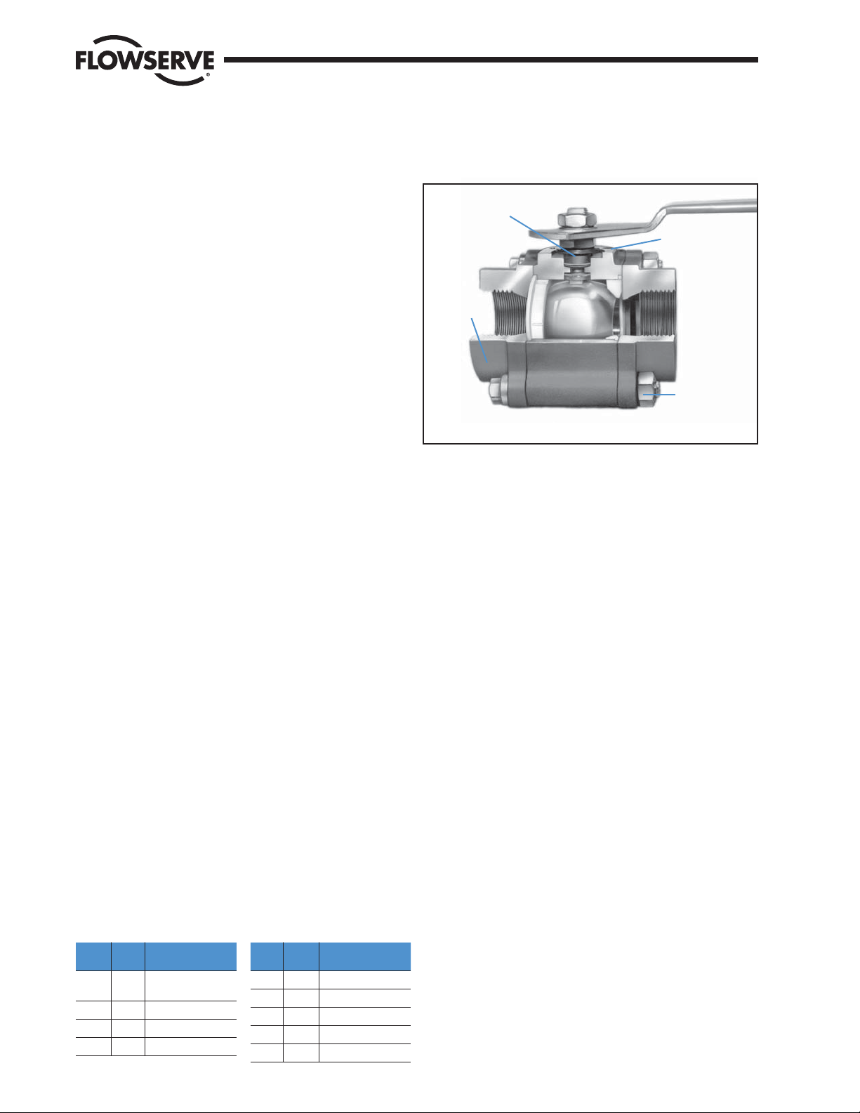
High cycle life
stem seals
Standardized center
body mounting
pad for actuators
Full ANSI
B16.34
compliance
Stainless steel nameplate to meet MSS SP-25
New, stronger
handle design
Heavy-duty
bolting and
valve construction
Design ANSI B16.34 (¼ "- 2", if ordered with Hydro Test)
Specifi cations: ANSI B16.25 – Butt Weld Ends
(Weld End Preparation)
ANSI B16.11
ANSI B1.20.1 – NPT Pipe Threads
MSS SP25 – Valve Marking
MSS SP72 – Socket Weld Ball Valves
NACE – MRO 1-75 Category 3
UL Listed: Flammable liquid shutoff (YRBX)
(¼ "- 2") Anhydrous ammonia shutoff (YQAR)
Compressed gas shutoff, including oxygen
(YQNZ)
Trim and drain valves (VQGU)
Weld-in-Place ¼ "- 1½ " Series 59 valves with “G” body
Valves (V67): seals and seats of reinforced TFE (R),
Polyfi ll
®
(P), or High-per Fill® (X) may be welded
to the pipeline in the assembled condition. (Must
have V67 suffi x in ordering code).
Optional S-7: (¼ "- 1½ ") Complete stainless steel trim: handle,
nut, lock washer, retaining nut, Belleville washers,
body bolts, nuts, stop pin.
External External components are available as an option
Valve Trim: on brass and carbon steel valves. They are
standard on ¼ "- 1½ " stainless steel valves.
For 2"- 4", they are available through custom
products. Certifi ed Material Testing Reports
(CMTRs) are available with B16.34.
Flow Coeffi cient
Flow coeffi cient and pressure loss through full-port ball valves are
the same as the pipe they are attached to.
Valve
Size
¼ ",
3
⁄8"
½ " 38 1.4
¾ " 71 1.0
1" 110 1.9
Equiv. Length of
C
v
Sched. 40 pipe (ft)
8 0.9
Valve
Size
1¼ " 230 2.1
1½ " 350 2.1
2" 600 2.1
3" 1330 3.0
4" 2420 2.7
C
v
Sched. 40 pipe (ft)
Equiv. Length of
Variations (V#)
V 3 Upstream Relief Hole V51 High Cycle Stem Build (2"- 4")
V 5 Hydrostatic Testing V58 B16.34 Compliance
V 6 Source Inspection V59 Extended Oval Handle (¼ "- 1½ ")
V14 Handleless Valve (2"- 4") V60 OSHA Lockout (¼ "- 1½ ")
V17 Grounding Thrust Bearing V66 Cert. of Comp., European orders
V20 Oxygen Service V67 Weld-in-Place Valve (¼ "- 1½ ")
V32 Oval Handle (¼ "- 1½ ") V72 Cert. of Comp., European Pressure
V33 Oxygen Service without Source Inspect. Equipment Directive Conformance
V36 Certifi cate of Compliance
V37 Certifi cate of Compliance & Hydro Testing
V38 Assemble without Lubricant
V46 Silicon Free Lubricant
V48 Extended Lever Handle (¼ "- 1½ ")
Page 3
Flow Control Division
Worcester Controls
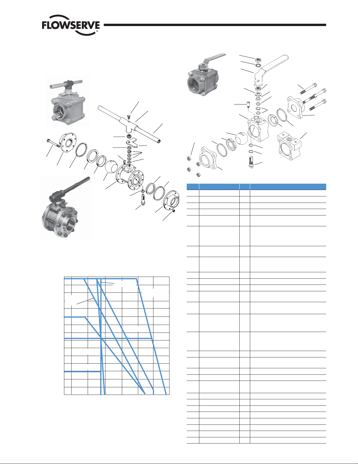
Parts Identifi cation and
Material Specifi cations
NOTE: 2" Series 59 valve has wrench block
handle and stem seal package similar to 3" and
4" valves.
25
26
27
2"
28
24
20
21
(3"- 4")
5
6
4
2
15
14
2
3" & 4"
9
13
6
23
5
3
1
22
NOTE: Standard Worcester valves are
assembled with silicon-based break-in lubricant.
For other options consult your distributor or
Flowserve.
4FBU1SFTTVSF5FNQFSBUVSF
3FJOGPSDFE
5'&
H
JTQFSVTTFS1
5'&
6).81&
#VOB
/FPQSFOF
Body seals have a pressure/temperature rating that equals or exceeds the seat.
* Oxygen Service Valves use Polyfi ll in place of PEEK.
Worcester®, Polyfi ll® and High-per Fill® are registered trademarks of Flowserve Corporation.
Viton® and Delrin® are registered trademarks of The DuPont Company.
3BUJOHT
%FMSJO"'
)JHIQFS'JMM
1PMZmMM
.FEJB5FNQFSBUVSF
11
16
12
10
¼ "- 1½ "
6
15
No. Part Qty Material
1 Body 1 C.S., 316 S.S., Brass
2 Pipe End 2 C.S., Brass, 316 S.S.,
3 Ball 1 316 S.S., Chrome-Plated Brass
4 Stem 1 316 S.S., Brass
5 Seat 2
6 Body Seal 2
7 Stem Seal 2
8 Thrust Bearing 1
9 Stem Seal Follower 1 316 S.S.
10 Belleville Washers 2 Carbon Steel: Zinc-Plated or S.S.
11 Retaining Nut 2 Carbon Steel: Zinc-Plated or S.S.
12 Handle Assembly 1
Stop Pin (1" and up)
13
(¼ "- ¾ ")
14 Body Bolts
15 Body Nuts
16 Lockwasher 1 Carbon Steel: Zinc-Plated or S.S.
17 Thrust Bearing* 1
18 Seal Protector* 1 PEEK
19 Nameplate
20 Stem Seal 3
21 Centering Washer 1 C.S.; 316 S.S. (3" & 4" only)
22 Thrust Bearing 1 Glass-fi lled TFE
23 Seat Retainer 1 Carbon Steel or 316 S.S.
24 Stop 1 C.S.: Black Oxide-Coated
25 Hex. Head Bolt 1 Carbon Steel
26 Wrench Block 1 Malleable Iron
27 Wrench Extension 1 Carbon Steel
28 Retaining Nut 1 Carbon Steel: Zinc-Plated or S.S.
13
(1"- 1½ ")
1
3
5
2
12 ¼ "- 1½ " S.S. or C.S. Zinc-Plated;
48¼ "-2" C.S.: ASTM A193 GR-B7
48¼ "-
(not shown) 1 304 Stainless Steel
11
9
18
7
8
17
4
TFE, Reinforced TFE, Buna, Neoprene,
Polyfi ll, UHMWPE, High-per Fill, Delrin
Buna, Viton
Coated 316 S.S. “S” Gasket, Graphite
Coated 316 S.S. “S” Gasket, UHMWPE
Graphite (2" only)
Polyfi ll
Graphite with High-per Fill Seats)
Polyfi ll
PEEK with High-per Fill seats; Delrin with
Delrin AF seats)
Carbon Steel: Zinc-Plated or S.S.
Vinyl Sleeve
2"-
S.S.: ASTM A193 GR-B8
3"- 4" C.S.: Black Oxide-Coated
S.S.: ASTM A194 GR-B8
3"-
PEEK
Delrin with Delrin AF seats)
Size 2", 3", 4" Valves
Glass-fi lled TFE
®
, EPR, TFE, Neoprene, TFE
(UHMWPE with UHMWPE seats;
(UHMWPE with UHMWPE seats;
4" C.S., Black Oxide-Coated
2" C.S.: ASTM A194 GR-2H
4" C.S.: Black Oxide-Coated
(UHMWPE with UHMWPE seats;
14
5
6
(316L for weld ends)
1
2
(
¼ "- ¾ ")
®
AF
Page 4
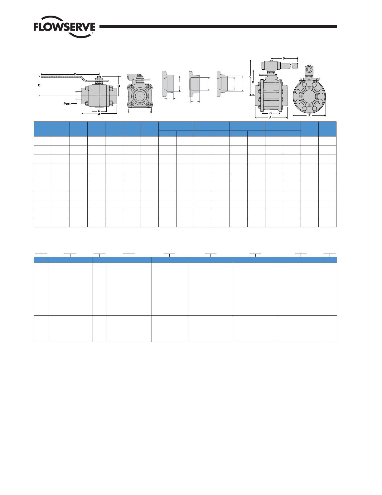
Dimensions
Flow Control Division
Worcester Controls
I.D.
H
M
O.D.
Valve
Size
¼ "
3
⁄8"
½ "
¾ "
1"
1¼ "
1½ "
2"
3"
4"
SOCKET WELD TUBE END BUTT WELD BW
SW TE SCH. 10 Stainless Steel
F
(Brass Only) SCH. 40 Carbon Steel
ABCDFG
2.54
1.55
1.76
5.53
1.75
(64.52)
2.54
(64.52)
2.76
(70.1)
3.66
(92.96)
4.16
(105.7)
4.50
(114.3)
4.94
(125.5)
5.86
(149.0)
7.54
(191.0)
11.75
(298.0)
(39.4)
1.55
(39.4)
1.64
(41.7)
2.19
(55.6)
2.38
(60.5)
2.88
(73.2)
3.06
(77.7)
4.56
(116)
6.31
(160.3)
8.96
(227.9)
(44.7)
1.76
(44.7)
1.86
(47.24)
2.28
(57.91)
2.47
(62.74)
2.83
(71.88)
3.02
(76.71)
5.58
(142.0)
7.84
(199.0)
11.21
(284.0)
(140.5)
5.53
(140.5)
5.53
(140.5)
6.53
(165.9)
6.53
(165.9)
8.03
(204.0)
8.03
(224.0)
8.82
(224.0)
22.00
(558.8)
26.00
(660.0)
(44.5)
(44.5)
(50.8)
(60.5)
(68.6)
(80.3)
(9.04)
(116.0)
(206.0)
11.13
(282.0)
1.75
2.00
2.38
2.70
3.16
3.56
4.57
8.13
.813
(20.7)
.813
(20.7)
.969
(24.6)
1.25
(31.8)
1.63
(41.3)
1.91
(48.4)
2.22
(56.3)
2.86
(72.6)
4.28
(108.0)
5.75
(146.0)
J
Socket Weld Tube End
HJMN
.555
(14.1)
.690
(17.5)
.855
(21.7)
1.07
(27.1)
1.33
(33.8)
1.68
(42.5)
1.92
(48.6)
2.41
(61.2)
3.54
(89.9)
4.53
(115.1)
.440
(11.2)
.440
(11.2)
.440
(11.2)
.560
(14.2)
.720
(18.3)
.720
(18.3)
.720
(18.3)
.840
(21.34)
1.31
(33.27)
1.56
(39.62)
N
.378
.370
(9.6)
(9.40)
.504
(12.8)
(15.6)
(22.3)
(28.7)
(35.0)
(41.4)
.449
(11.2)
.628
.560
(14.2)
.878
.810
(20.6)
1.13
(24.6)
1.38
1.03
(25.2)
1.63
1.15
(29.2)
——
——
——
Butt Weld
Scheduled 10
O.D. I.D. O.D. I.D.
.550
.406
(14.4)
(10.3)
.670
.547
(17.0)
(13.9)
.840
.672
(21.3)
(17.1)
1.05
.875
(26.7)
1.31
(33.3)
1.66
(42.2)
1.91
(48.5)
2.38
(60.5)
3.50
(88.9)
4.50
(114.3)
(22.2)
1.09
(27.8)
1.44
(36.5)
1.67
(42.5)
2.15
(54.5)
3.25
(82.55)
4.26
(108.2)
.97
Butt Weld
Scheduled 40
.550
(14.4)
.670
(17.0)
.840
(21.3)
1.05
(26.7)
131
(33.3)
1.66
(42.2)
1.91
(48.5)
2.38
(60.5)
3.50
(88.9)
4.50
(114.3)
.344
(8.7)
.516
(13.1)
.625
(15.9)
.812
(20.6)
1.05
(26.6)
1.38
(35.1)
1.59
(40.5)
2.06
(52.3)
3.07
(77.98)
4.03
(102.4)
Port
.440
(11.2)
.440
(11.2)
.560
(14.2)
0.81
(20.6)
1.00
(25.4)
1.25
(31.8)
1.50
(38.1)
2.00
(50.8)
3.25
(82.55)
4.03
(102.4)
Dimensions are given for layout purposes only. For tolerances, consult your Worcester distributor. Metric equivalents are converted from Standard English.
How To Order*
1½ "
Size Options Series Body, Pipe Ends Ball & Stem Seat Body Seal Pipe End V#
Bla nk - Built with
¼ "
lever handle
3
⁄8"
E - No handle valve built
for automation
½ "
A - No handle††
B - No handle††
¾ "
G - Stem Grounding
1"
Spring
K - Locking Handle
1¼ "
V - Vacuum Service Prep
X - Oxygen Service Prep
1½ "
2"
E - No handle valve built
for automation
3"
V - Vacuum Service Prep
4"
X - Oxygen Service Prep
** Variations (V-numbered options) Leave blank if no variations. See page 2 for listing.
* Ordering example depicts 1½ " Series 59 with 316 stainless steel body, pipe ends, ball and stem, reinforced TFE seats, TFE body seals, and socket weld ends.
†† To order a Series 59 Valve for use with: 34 or 36 actuators, use prefi x ordering code “A”. Example: 1" A 5946 PMSE. 39 or 75 actuators, use prefi x ordering code “B”.
Caution: Ball valves can retain pressurized media in the body cavity when closed. Use care when disassembling. Always open valve to relieve pressure prior to
disassembly. Due to continuous development of our product range, we reserve the right to alter the dimensions and information contained in this brochure as required.
59 1 - Brass
(
¼ "- 1½ "
4 - Carbon Steel
6 - 316 S.S.
59 4 - Carbon Steel
6 - 316 S.S.
only)
1 - Brass
6 - 316 S.S.
6 - 316 S.S. T - TFE
T - TFE
R - Reinforced TFE
U - UHMWPE
(¼ "- 1½ " only)
P - Polyfi ll
X - High-per Fill
B - Buna
N - Neoprene
Y - Delrin AF
R - Reinforced TFE
P - Polyfi ll
TR6659
T - TFE
B - Buna (Brass only)
V - Viton
E - EPR
M - TFE coated 316 S.S.
“S” gasket
G - Graphite Coated
316 S.S. “S” gasket
U - UHMWPE
N - Neoprene
T - TFE
Z - Graphite (2" only)
SW
SE - Screw End
SW - Socket Weld
TE - Tube End
(Brass Only)
BW1 - Butt Weld
Schedule 10,
Stainless Steel
BW4 - Butt Weld
Schedule 40,
Carbon Steel,
Stainless Steel
NP - No Pipe Ends
SE - Screw End
SW - Socket Weld
BW1 - Butt Weld, S.S.
BW4 - Butt Weld, C.S.,
S.S. (2" only)
NP - No Pipe Ends
Weight
lb.
(kg)
1.10
(0.5)
1.10
(0.5)
1.80
(0.82)
3.10
(1.41)
4.50
(2.05)
6.20
(2.81)
9.50
(4.31)
25.00
(11.3)
50.20
(22.8)
80.10
(36.4)
**
Flowserve Corporation has established industry leadership in the design and manufacture of its products. When properly selected, this Flowserve product is designed to perform
its intended function safely during its useful life. However, the purchaser or user of Flowserve products should be aware that Flowserve products might be used in numerous
applications under a wide variety of industrial service conditions. Although Flowserve can (and often does) provide general guidelines, it cannot provide specifi c data and warnings
for all possible applications. The purchaser/user must therefore assume the ultimate responsibility for the proper sizing and selection, installation, operation, and maintenance of
Flowserve products. The purchaser/user should read and understand the Installation Operation Maintenance (IOM) instructions included with the product, and train its employees
and contractors in the safe use of Flowserve products in connection with the specifi c application.
While the information and specifi cations contained in this literature are believed to be accurate, they are supplied for informative purposes only and should not be considered
certifi ed or as a guarantee of satisfactory results by reliance thereon. Nothing contained herein is to be construed as a warranty or guarantee, express or implied, regarding any
matter with respect to this product. Because Flowserve is continually improving and upgrading its product design, the specifi cations, dimensions and information contained herein
are subject to change without notice. Should any question arise concerning these provisions, the purchaser/user should contact Flowserve Corporation at any one of its worldwide
operations or offi ces.
For more information about Flowserve Corporation, visit www.fl owserve.com or call USA 1 800 225 6989.
FLOWSERVE CORPORATION
FLOW CONTROL DIVISION
1978 Foreman Drive
Cookeville, Tennessee 38501 USA
Phone: 931 432 4021
Facsimile: 931 432 3105
www.fl owserve.com
(Part PB-451)
© 2004 Flowserve Corporation, Irving, Texas, USA. Flowserve is a registered trademark of Flowserve Corporation. FCD WCABR1011-00 Printed in USA.
 Loading...