

Page 1
Installation, Operation, Maintenance Instructions
Pneumatic and
Electropneumatic Actuators
Series 4, Types 37, 38, 39, 3D and 47, 48, 49, 4D
Flow Control Division
Kammer Control Valves
Index
1 Using Kämmer valves and actuators correctly.
2Unpacking
3 Installation
4 Quick check / Maintenance
5 Methode of operation
6 Remove and install actuator
7 Disassemble and assemble actuator
8 Calibration / Technical data
1 USING KÄMMER VALVES AND ACTUATORS
CORRECTLY
1.1 General
The following instructions are designed to assist in
unpacking, installing and performing maintenance as
required on Kämmer products. Product users and
maintenance personnel should thoroughly review this
bulletin prior to installing, operating or performing
any maintenance.
DANGER:
are designed for specific applications (e.g. with regard
to medium, pressure, temperature). For this reason
they should not be used in other applications without
first contacting the manufacturer.
1.2 Terms concerning safety
The safety terms DANGER, WARNING, CAUTION and
NOTE are used in these instructions to highlight
particular dangers and/or to provide additional
information on aspects that may not be readily
apparent.
DANGER:
and/or substantial property damage will occur if
proper precautions are not taken.
STOP!
WARNING:
and/or substantial property damage can occur if
proper precautions are not taken.
CAUTION:
In most cases Kämmer valves and actuators
indicates that death, severe personal injury
indicates that death, severe personal injury
indicates that minor personal injury and/
or property damage can occur if proper precautions
are not taken.
NOTE:
information, which may not be very obvious even to
qualified personnel.
Compliance with other, not particularly emphasised
notes, with regard to transport, assembly, operation
and maintenance and with regard to technical
documentation (e.g. in the operating instruction,
product documentation or on the product itself) is
essential, in order to avoid faults, which in themselves
might directly or indirectly cause severe personal
injury or property damage.
1.3 Protective clothing
Kämmer products are often used in problematic
applications (e.g. extremely high pressures, dangerous, toxic or corrosive mediums). In particular
valves with bellows seals point to such applications.
When performing service, inspection or repair
operations always ensure, that the valve and actuator
are depressurised and that the valve has been cleaned
and is free from harmful substances. In such cases
pay particular attention to personal protection
(protective clothing, gloves, glasses etc.).
1.4 Qualified personnel
Qualified personnel are people who, on account of
their training, experience and instruction and their
knowledge of relevant standards, specifications,
accident prevention regulations and operating
conditions, have been authorised by those responsible
for the safety of the plant to perform the necessary
work and who can recognise and avoid possible
dangers.
1.5 Installation
DANGER:
serial-no. and/or the tag-no. to ensure that the valve/
actuator is correct for the intended application.
Do not insulate extensions that are provided for hot
or cold services.
Pipelines must be correctly aligned to ensure that the
valve is not fitted under tension.
indicates and provides additional technical
Before installation check the order-no,
KMEIM0006-00 - 08.03
1
Page 2
Flow Control Division
Kammer Control Valves
1.6 Spare parts
Use only Kämmer original spare parts. Kämmer
cannot accept responsibility for any damages that
occur from using spare parts or fastening materials
from other manufactures. If Kämmer products
(especially sealing materials) have been on store for
longer periods check these for corrosion or deterioration before using these products. Fire protection for
Kämmer products must be provided by the end user.
1.7 Service / repair
To avoid possible injury to personnel or damage to
products, safety terms must be strictly adhered to.
Modifying this product, substituting nonfactory parts,
or using maintenance procedures other than outlined
in this instruction could drastically affect performance
and be hazardous to personnel and equipment, and
may void existing warranties. Between actuator and
valve there are moving parts. To avoid injury
Flowserve provides pinch-point-protection in the form
of cover plates, especially where side-mounted
positioners are fitted. If these plates are removed for
inspection, service or repair special attention is
required. After completing work the cover plates must
be refitted.
Apart from the operating instructions and the
obligatory accident prevention directives valid in the
country of use, all recognised regulations for safety
and good engineering practices must be followed.
WARNING:
for repair or service Kämmer must be provided with
STOP!
Before products are returned to Kämmer
a certificate which confirms that the product has been
decontaminated and is clean. Kämmer will not accept
deliveries if a certificate has not been provided (a form
can be obtained from Kämmer).
1.8 Storage
In most cases Kämmer Products are manufactured
from stainless steel. Products not manufactured from
stainless steel are provided with an epoxy resin
coating. This means that Kämmer products are well
protected from corrosion. Nevertheless, Kämmer
products must be stored adequately in a clean, dry
environment. Plastic caps are fitted to protect the
flange faces and to prevent the ingress of foreign
materials. These caps should not be removed until
the valve is actually mounted into the system.
1.9 Valve and actuator variations
These instructions cannot claim to cover all details
of all possible product variations, nor in particular
can they provide information for every possible
example of installation, operation or maintenance.
This means that the instructions normally include only
the directions to be followed by qualified personal
where the product is being used for is defined
purpose. If there are any uncertainties in this respect
particularly in the event of missing product-related
information, clarification must be obtained via the
appropriate FLOWSERVE sales office.
2 UNPACKING
2.1 Each delivery includes a packing slip. When unpacking, check all delivered valves and accessories using
this packing slip.
2.2 Larger valves can be lifted using slings on the yoke
rods or, if present, on the lugs provided for this
purpose. If slings are used, attach them so that the
outer tubing or attaching parts are not damaged.
WARNING:
If slings are used, be aware that the cen-
tre of gravity of the valve may be above the lifting
STOP!
point. In this case, secure or support the valve against
rotating, to prevent damage or personnel injury.
2.3 Report transport damage to the carrier immediately.
2.4 In case of discrepancies, contact your nearest
FLOWSERVE sales office.
3 INSTALLATION
3.1 Clean tubing prior to installing.
3.2 If possible, install the valve in an upright position
(actuator on top), to ease maintenance. An upright
installation position is important with low-temperature applications, in order to keep the distance between the packing material and the medium as large
as possible. The packing material then retains the
ambient temperature as much as possible.
NOTE:
Do not insulate extension bonnets that are pro-
vided for hot or cold services
3.3 Make sure that sufficient overhead clearance above
the actuator is maintained, to allow for disassembly
of plug from the valve body (see following table).
Actuator Clearance Actuator Clearance
size (mm) size (mm)
37/47 95 P2 140
38/48 140 P3 140
39/49 140 P4 140
39D/49D 140 P5 140
3.4 After installing, check direction of flow again. The
direction of flow is shown by the arrow on the
housing.
3.5 If the valve is to be welded into the line, make sure that
the valve is shielded from excessive heat.
3.6 Connect supply pressure and signal lines. Control
valves are supplied with a positioner. The end connections for supply pressure and signal are clearly
marked. Series 4 actuators and positioners are suitable for max. 4.2 bar (60 psi) supply pressure. If the
supply pressure exceeds the pressure specified on
the nameplate, a pressure reducing station is required. If instrument air is not available, install an oil
separator/air filter in the air inlet line. All connections
must be leak free.
2
Page 3
Flow Control Division
Kammer Control Valves
4 QUICK CHECK / MAINTENANCE
4.1 QUICK CHECK
Before operating, check the valve as follows:
4.1.1 Open and close the valve, and observe the movement
of the actuator stem. The movement must be smooth
and linear.
4.1.2 Check for maximum stroke through change of signal
(for pneumatic positioners, 0.2 - 1.0 bar or corresponding split-range values; for IP positioners, 4-20
or 0-20 mA).
4.1.3 Check all air connections for leaks.
4.1.4 Tighten packing nut (see table 1).
Torque
Thread PTFE Grafoil
M20 x 1,5 1 3
M30 x 1,5 6 15
M38 x 1,5 15 35
M45 x 1,5 17 40
Table 1
NOTE:
An excessively tightened gland nut can cause
excessive packing wear and can hinder the free movement of the plug stem.
4.1.5 Check fail-safe position. To do this, close supply
pressure and observe whether the valve opens or
closes as defined.
4.1.6 After use at fluctuating temperatures, re-tighten all
bolt connections and check for leaks.
4.2 Maintenance
Check valves for correct functioning at regular intervals (at least once every 6 months) as follows. This
check can be made when installed and in many
cases without interrupting production. If internal defects are suspected, see section „Disassembly and
Assembly of Valve“.
4.2.1 Examine gaskets for leaks and if necessary re-tighten
bolts (see Fig. 1).
4.2.2 Check bellows gasket and test connection - if present
- for external leaks.
4.2.3 Check valve for damage caused by corrosive residues
or corrosive vapours.
4.2.4 Clean valves and repaint as necessary.
STOP!
Warning:
clean the actuator/valve with a damp cloth only.
To prevent a buildup of electrostatic charge
4.2.5 Check gland nut for correct torque (see table 1).
NOTE:
An excessively tightened gland nut can cause
excessive packing wear and can hinder the free movement of the plug stem.
4.2.6 If possible, open and close valve and check for
maximum stroke and smooth movement of the plug
stem. Irregular movement of the plug stem may
indicate internal defects.
NOTE: With graphite packing, irregular movement of
the plug stem is normal.
STOP!
WARNING:
all moving parts. Failure to do so can lead to serious
Keep hands, hair, clothing, etc. away from
injury.
4.2.7 Check all accessories for firm seating.
4.2.8 If possible, close supply pressure and check the failsafe position.
4.2.9 Check stem boot for wear.
4.2.10 Check actuator for leaks. To do this, spray housing,
air connections and plug stem guide with leak spray
and check for any bubble formation.
4.2.11 Clean plug stem.
4.2.12 Check air filter, if present, and if necessary replace
insert.
Note:
For further information regarding service and
maintenance please contact your nearest FLOWSERVE
office.
DANGER:
On actuators with aluminium cases the
actuator springs must be renewed with original spare
parts every 10 years or after 50.000 operating hours
which ever occurs first.
3
Page 4
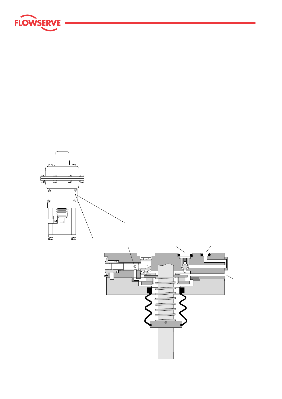
5 Method of operation (actuators with integral Kämmer positioner)
5.1 P/P Actuator
The actuator with integrated pneumatic positioner works on the force balance principal, which ensures that the
position of the actuator stem is proportional to the value of the input signal (see figs. 1 and 2).
An increased signal to the double diaphragm assembly creates an unbalanced condition. The pilot valve then
moves to cover the vent, increasing the positioner output pressure to the actuator diaphragm until the forces of
the positioner spring and the double diaphragm are equal. The positioner output is then stabilized at an amount
necessary to maintain the desired valve position.
Flow Control Division
Kammer Control Valves
Signal input
Fig. 1: P/P - Positioner
Supply
To actuator
Vent
4
Page 5
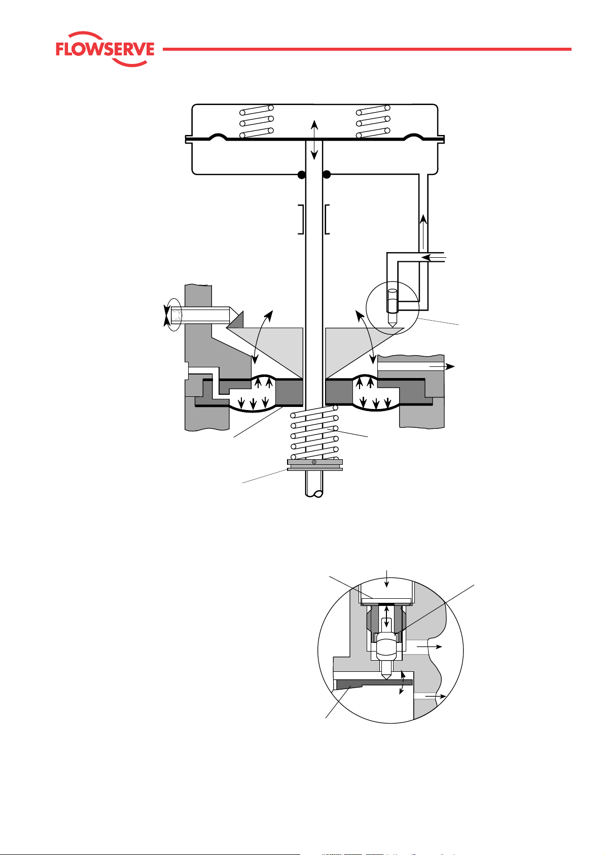
Range adjustment screw
(max. 3 turns)
Flow Control Division
Kammer Control Valves
Supply output to
actuator diaphragm
Supply input
1.4–4.2 bar (20–60 psi)
Pilot plug
(see detail below)
Signal input
0.2–1.0 bar
(3–15 psi)
Double diaphragm
Adjusting nut
Seat ring
Vent
Positioner spring
Supply input
1.4 – 4.2 bar
(20 – 60 psi)
Pilot valve
Supply to
actuator diaphragm
Balancing plate
Pilot plug
Fig. 2: P/P - Positioner
Vent
5
Page 6
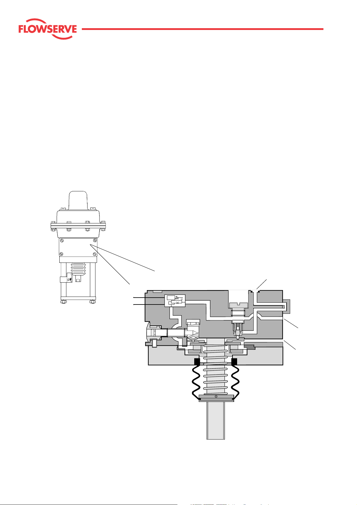
5.2 I/P Actuator
The I/P transducer, which is an integral part of the actuator, converts the standard electric signal
(0/4 – 20 mA) into a standard pneumatic signal (0.2 – 1.0 bar) by means of a system of light weight moving
parts. This form of signal conversion is extremely insensitive to shocks. The pneumatic signal is supplied to the
integrated pneumatic positioner.
The pneumatic positioner works on the force balance principal, which ensures that the position of the actuator
diaphragm is always directly proportional to the value of the instrument input signal pressure (see figs. 3 and 4).
An increased signal to the double diaphragm assembly creates an unbalanced condition. The pilot valve then
moves to cover the vent, increasing the positioner output pressure to the actuator diaphragm until the forces
of the positioner spring and the double diaphragm are equal. The positioner output is then stabilized at an amount
necessary to maintain the desired valve position.
Flow Control Division
Kammer Control Valves
Signal
To actuator
Supply
Vent
Fig 3: I/P Positioner
6
Page 7
Transducer
Flow Control Division
Kammer Control Valves
Signal
0/4 – 20 mA
Signal input
0.2–1.0 bar (3–15 psi)
Range adjustment screw
(max. 3 turns)
Double diaphragm
Adjusting nut
Seat ring
Supply output to
actuator diaphragm
Supply input
1.4–4.2 bar (20–60 psi)
Pilot plug
(see detail below)
Vent
Positioner spring
Supply input
1.4 – 4.2 bar
(20 – 60 psi)
Pilot valve
Balancing plate
Fig. 4: I/P Positioner
Supply to
actuator diaphragm
Vent
Pilot plug
7
Page 8
Flow Control Division
Kammer Control Valves
2
1
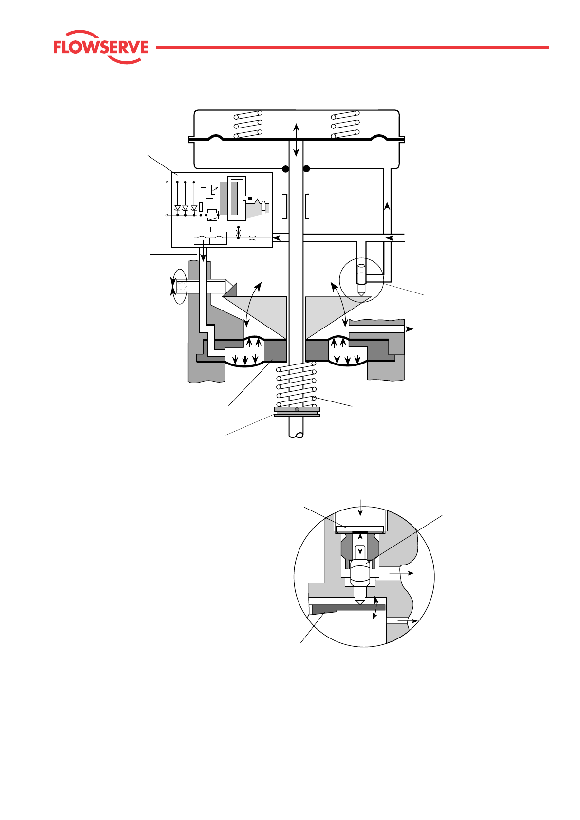
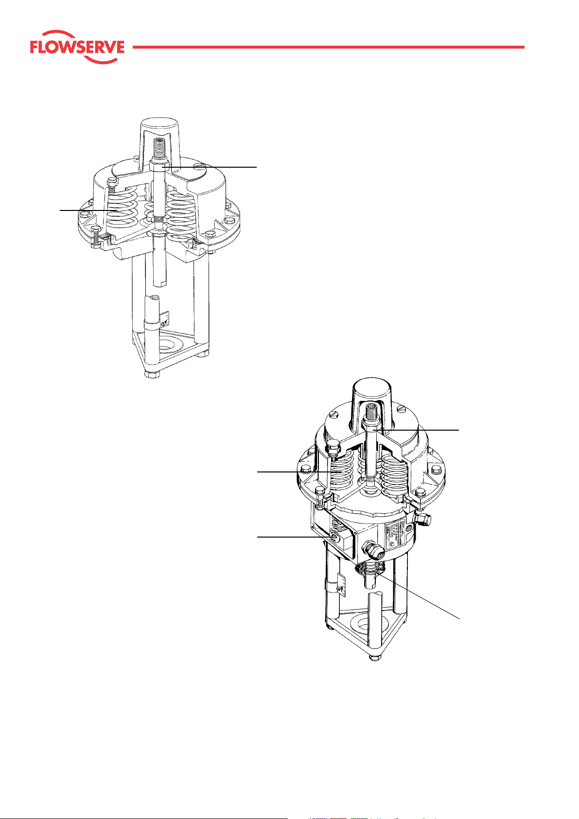
Series 47 / 48 / 49
(without positioner)
2
1
3
4
Series 37 / 38 / 39
(with positioner)
Fig. 5
8
Page 9

5.3 Actuator Springs - (fig. 5 pos. 1)
Different actuator spring sets are available depending on the actuator thrust requirements and the fail
position of the actuator. The appropriate spring set can be chosen from the spare parts list.
5.4 Zero Adjustment Locknut - (fig. 5 pos. 2)
The zero adjustment locknut is used as a mechanical stop so that the actuator just begins to travel when
the desired signal is applied to the positioner.
5.5 Range Adjustment - (fig. 5 pos.3)
(Actuator with positioner only)
The actuator travel is adjusted by means of the range adjustment screw. Turn the range adjustment screw
so that the actuator stem travels the required distance in response to the positioner input signal.
5.6 Positioner Spring - (fig. 5 pos. 4)
(Actuator with positioner only)
To change the signal range from full to split range the positioner spring must be changed.
Flow Control Division
Kammer Control Valves
Examples:
from 3-15 psi to 3-9 psi or 9-15 psi
from 4-20 mA to 4-12 mA or 12-20 mA
Notice that split ranging on electro-pneumatic actuator is also done by means of the positioner spring.
After removal of the spring boot and retaining ring on older actuators or by removing the boot, positioner
spring adjustment nut on newer actuators, the spring can be replaced.
9
Page 10

Flow Control Division
Kammer Control Valves
Air-to-open Air-to-close
5.7 Changing the Actuator Action
To change the actuator action from fail-open to fail-closed, or vice versa, the complete actuator
must be reversed. Remove the yoke assembly and actuator cap, invert the actuator and replace all
parts. If necessary, use other spring sets (see spare parts list) according to the actuator thrust
requirements.
Fig. 6
10
Page 11

Flow Control Division
Kammer Control Valves
Gasket
O - Ring
Connection "EXT"
For positioner without "EXT" cover
on the reverse side exchange
position of gasket and O-ring.
Fig. 7a
Special O - Ring
5.8 External Piping
When using solenoid valves (not NAMUR), lock-up valves, volume boosters, etc.; external piping is possible
without the need of additional parts. Solenoid valves to NAMUR-standard (modified) can be bolted directly onto
the positioner body.
Positioner without "EXT" cover on the reverse side:
Exchange position of gasket and O - ring (Fig. 7a).
Remove the plugs marked "EXT" from the positioner body and diaphragm case.
Accessories can now be piped between the positioner and diaphragm case.
Positioner with "EXT" cover on the reverse side:
Exchange the position of the O - ring and special O - ring in the "EXT" cover. (Fig. 7b)
Remove the plugs marked "EXT" from the positioner body and diaphragm case.
Accessories can now be piped between the positioner and diaphragm case.
Connection "EXT"
"EXT" cover
O - Ring
For positioner with "EXT" cover on the
reverse side exchange position of
O - ring and special O-ring.
Fig. 7b
11
Page 12

Flow Control Division
Kammer Control Valves
Cap
Zero adjustment locknut
Upper coupling half
Lip serves as travel
indicator
Actuator stem
Screw
Travel indicator
Plug stem locknut
Packing gland nut
Actuator clamp nut
Valve plug stem
Coupling insert
Lower coupling half
Locknut
Plug stem
Valve/actuator with coupling
(see page 23)
12
Fig. 8: Typical actuator and valve configuration
Page 13

Kammer Control Valves
6 GENERAL SERVICE INFORMATION
Service to the actuator is best performed when the actuator is removed from the valve body.
For the purpose of these instructions, consider the actuator as a separate subassembly with the procedures
described in these instructions being performed on a bench. However, many service repairs and adjustments
can be accomplished in the field while the actuator and valve body are still connected to each other.
Flow Control Division
6.1 REMOVING ACTUATOR FROM VALVE BODY
DANGER:
Depressurise the line to atmospheric pressure
and drain all fluids from the valve before working on the
actuator. Failure to do so can cause serious injury.
For air-to-open actuators start with 6.1.1
For air-to-close actuators start with 6.1.2.1
6.1.1 Remove the valve cap and nameplate. Turn the zero adjustment locknut until it just makes contact with the actuator
spring case (this removes the spring force from the valve
plug).
6.1.2 Valve/actuator without coupling
6.1.2.1 With a wrench, hold the actuator stem to prevent it from
rotating while using a second wrench to loosen the plug
stem locknuts.
If the actuator stem is rotated the diaphragm will be
NOTE:
twisted and this may cause irreparable damage.
6.1.2.2 Loosen the packing gland nut and the actuator clamp nut.
6.1.2.3 Being sure not to turn the plug stem, rotate the actuator
assembly counterclockwise to disengage the actuator stem
from the valve plug stem.
NOTE:
Ensure that the plug assembly is not rotated with the
plug seated. This may cause irreparable damage to the
seating faces.
6.1.2.4 Lift the actuator assembly from the valve body subassembly.
At the same time, remove the plug stem locknuts, the travel
indicator disc, packing gland nut, and clamping nut.
6.1.3 Valve/actuator with coupling
6.1.3.1 With a wrench, hold the actuator stem to prevent it from
rotating while using a second wrench to loosen and remove
coupling screws.
6.1.3.2 Remove the yoke rod nuts and lift actuator assembly
from the valve.
6.2 CONNECTING ACTUATOR TO VALVE BODY
General Notes:
• The actuator must be calibrated before connecting it to the
valve body. See section 3 "Calibration" of these instructions.
6.2.1 Valve/actuator without coupling
6.2.1.1 Place the actuator assembly onto the valve body
subassembly. At the same time, install the clamping nut,
packing gland nut, plug stem locknuts, and the travel indicator disc.
6.2.1.2 "Air-to-open/fail-to-close" actuators only:
Rotate the actuator assembly clockwise, threading the actuator stem onto the plug stem until the yoke plate just
makes contact with the bonnet flange, and the actuator is
properly aligned for installation.
NOTE:
Ensure that the plug assembly is not rotated with the
plug seated. This may cause irreparable damage to the
seating faces.
"Air-to-close/fail-to-open" actuators only:
Lift the plug stem to the actuator stem. Thread the plug stem
into the actuator stem so that the distance "plug in seat", to
"plug raised", is approximately the distance of the specified
stroke.
6.2.1.3 Tighten the clamping nut and the packing gland nut (see
valve service instructions for torque values).
6.2.1.4 Adjust the valve plug for seat off by threading the plug stem
further into or out of the actuator stem.
rotate the plug stem while the valve is in the closed
NOTE:
position. Open the valve first, make the adjustment while the
valve is open, and then close the valve to check for seat-off.
6.2.1.5 After final adjustments are made, lock the two stem nuts
against the actuator stem and set the position of the travel
indicator on the yoke rod.
6.2.2 Valve/actuator with coupling
6.2.2.1 Place actuator onto valve.
6.2.2.2 Screw on and tighten yoke rod nuts.
6.2.2.3 Fit the coupling screws finger tight.
6.2.2.4 Adjust the valve plug for seat off by threading the plug stem
further into or out of the coupling insert.
rotate the plug stem while the valve is in the closed
NOTE:
position. Open the valve first, make the adjustment while the
valve is open, and then close the valve to check for seat-off
• All worn or damaged parts must be replaced. All parts to be
reused should be cleaned for ease of reassembly.
6.2.2.5 After final adjustment tighten the coupling screws and set
the position of the travel indicator on the yoke rod.
13
Page 14

13
Flow Control Division
Kammer Control Valves
12
15
14
17
16
11
10
9
8
6
5
2
1
7
3
1
4
2
14
Series 47 / 48 / 49
(without positioner)
Series 37 / 38 / 39
(with positioner)
Fig. 9
Page 15

Flow Control Division
Kammer Control Valves
7 ACTUATOR DISASSEMBLY and ASSEMBLY
7.1 ACTUATOR DISASSEMBLY
(refer to figs. 9 and 11)
NOTE:
To help reassembly note or mark the rela-
tionship between the parts to be disassembled.
7.1.1 Remove yoke plate (1) and yoke rods (2).
For actuators without positioner continue with
7.1.5.
7.1.2 Actuators without adjustable positioner spring
(see Fig. 9)
Remove the positioner spring boot (3), retaining
ring (4), seating washer (5), and positioner spring
(6).
Actuators with adjustable positioner spring
(see Fig. 15)
Loosen the set screw in the positioner spring
adjusting nut and remove the nut. Remove boot
and positioner spring.
7.1.3 Loosen and remove the positioner cover screws
(7), positioner cover (8), double diaphgram (9)
and balancing plate (10).
7.1.4 Remove the positioner (11). All inner positioner
parts are now accessible for replacement or maintenance (
11
for positioner details see figs. 10 and
).
7.2 ACTUATOR ASSEMBLY
(refer to figs. 9 to 13)
7.2.1 Install the diaphragm and diaphragm plate on the
actuator stem. Use Loctite® #242 on the threaded
portion of the actuator stem where the clamping
nut (14) is to be installed. Install and tighten the
clamping nut, being sure not to kink the diaphragm.
7.2.2 Place the spring set into the spring case so that
they sit in the recessed area of the case (15).
Smaller diameter springs are placed inside of
larger diameter springs.
7.2.3 Insert the actuator stem through the hole in the
spring case (15).
7.2.4 Install the zero adjustment locknut (13) on the
actuator stem and tighten it down fully to compressing the springs.
DANGER:
A press must be used to compress the
springs when high thrust spring sets are installed
or when actuator stroke is 40 mm.
7.2.5 Before inserting a new O-ring (16) in the diaphragm case, pack the O-ring groove with a multitemperature assembly paste
7.2.6 Replace the diaphragm gasket (17) and install the
diaphragm case onto the spring case assembly.
7.2.7 Install and tighten all case screws (12), washers
and nuts using a crisscross pattern.
7.1.5 Loosen and remove all case screws (12).
DANGER:
Actuators with high thrust spring sets
and/or actuators with 40 mm (1.5") stroke must be
held in a press to prevent possible injury when
removing the case screws.
7.1.6 Unscrew the zero adjustment lock nut (13).
7.1.7 The spring case and diaphragm case can now be
separated, and the springs removed.
7.1.8 Holding the actuator stem, unscrew and remove
the clamping nut (14) to service the actuator
diaphragm and diaphragm plate.
Continued....
15
Page 16

19
Flow Control Division
Kammer Control Valves
18
Range adjustment pin
10
9
Positioner
Fig. 11
Signal orifice
16
Balancing plate
Balancing plate assembly
Fig. 12
Double diaphragm
Fig. 13
Page 17

(7.4 Actuator assembly continued)
Flow Control Division
Kammer Control Valves
7.4.8 to 7.4.11 for actuator with positioner only.
7.2.8 Assemble the positioner using new O-rings, gas-
kets and filters and install the positioner body (see
figs. 11).
7.2.9 Install the balancing plate (10) so that the small
hole fits over the plastic range adjustment pin (see
fig.12), and the bevelled side faces the double
diaphragm (flat side to positioner).
7.2.10 Install the double diaphragm assembly (9) aligning the small hole in the diaphragm with the hole
in the diaphragm ring and the signal orifice in the
positioner body (see fig. 13).
7.2.11 Actuator without adjustable positioner spring
(see Fig 9)
Install the positioner cover (8), positioner cover
screws (7), positioner spring (6), seating ring (5),
retaining ring (4), and positioner spring boot (3).
Actuator with adjustable positioner spring
(see Fig 15)
Install the positioner cover, positioner cover
screws, positioner spring and positioner spring
boot. Thread adjusting nut onto actuator stem and
adjust roughly using the gauge (lower edge of
adjusting nut the underside of positioner cover).
7.2.12 Refit yoke rods (2) and yoke plate (1).
The actuator is now ready to be calibrated.
7.3 POSITIONER SERVICE
The KÄMMER integral positioner is designed to be a
maintenance free unit. However; moisture, oil and dirt
entering the positioner can dampen its performance,
which will cause the need for maintenance and repair.
When this happens, remove all internal parts and clean
them thoroughly. Replace all O-rings, filters and damaged parts, and reassemble the positioner body according to fig. 11.
Positioners with integral I/P transducers are more
sensitive to contaminants than those without. Therefore, it is very important that all parts to be reused are
extremely clean and dry.
I/P transducer
To remove the I/P transducer, disconnect the wires
from the terminal block and loosen the set screw (19)
on the side of the positioner housing. The I/P transducer can then be pulled from the front of the positioner housing. The main cause of transducer malfunction is a polluted air supply. Filters are situated in
the input and output orifices of the transducer and are
readily accessible after removing the O-rings. Apart
from the O-rings and filters the transducer contains no
user serviceable parts. The transducer is factory adjusted to exactly 4 – 20 mA or 0 – 20 mA (documented
by a sticker on the transducer cover) and an attempt to
field calibrate is not recommended. For repair and/or
calibration the transducer assembly should be returned to Kämmer.
17
Page 18

Zero adjustment locknut
Dim. "A"
Flow Control Division
Kammer Control Valves
Range adjustment screw
(max. 3 turns)
Positioner spring
Adjusting nut
Fig. 14: Dial gauge
Actuator stem
KÄMMER
Type
H
10
39D>
37/38/39
10
39D<
10
39D>
20
20
37/38/39
20
39D<
10
38-2
40
39D>
38-2
20
39
40
39D<
40
Gauge
Set screw
Adjust positioner spring with gauge
Fig. 15
KÄMMER
Type
39D>
37/38/39
39D<
39D>
37/38/39
39D<
38-2
39D>
38-2
39
39D<
Gauge (scale 1:1)
H
10
10
10
20
20
20
10
40
20
40
40
63 mm
8 Calibration
Calibrate actuator
(actuator without adjustable positioner spring)
8.1 Range adjustment
See nameplate for signal range, supply pressure
and stroke.
8.1.1 Connect air supply to the "SUPPLY" port of the
actuator and an adjustable signal source to the
18
"SIGNAL" connection. Attach a dial gauge to the
actuator (see Fig 14).
8.1.2 Undo the zero adjustment locknut until it is a few
threads free of the actuator housing. Set the
signal to the low end value (e.g. 0,2 bar or 4 mA).
Adjust the dial gauge to zero.
8.1.3 Set the signal to the high end value (e.g. 1,0 bar or
20 mA).
Page 19

Flow Control Division
Kammer Control Valves
8.1.4 Using the range adjusting screw set the actuator to full
stroke + 1.5 mm (e.g. stroke 20 + 1.5 mm = 21.5 mm).
8.1.5 Make adjustment with the range adjusting screw as
required until desired stroke is obtained
8.2 Zero adjustment
3.2.1 The zero adjustment can only be set after the final
range adjustment has been made.
8.2.2 Maintain the low end signal (e.g. 0.2 bar or 4 mA) and
turn the zero adjustment locknut until it just makes
contact with the actuator housing.
8.3 Calibrate actuator
(actuator with adjustable positioner spring)
See nameplate for signal range, supply pressure and
stroke.
8.3.1 Connect air supply to the "SUPPLY" port of the actuator and an adjustable signal source to the "SIGNAL"
connection. Attach a dial gauge to the actuator (see Fig
14).
8.3.2 Undo the zero adjustment locknut until it is a few
threads free of the actuator housing.
Loosen the set screw and thread the adjusting nut on
the actuator stem until it's lower face is in alignment
with the appropriate type designation on the gauge.
8.3.3 Set the signal to the low end value (e.g. 0.2 bar or 4
mA). Adjust the dial gauge to zero.
8.3.4 Set the signal to the high end value (e.g. 1.0 bar or 20
mA).
8.3.5 Using the range adjusting screw set the actuator to full
stroke + 1.5 mm (e.g. stroke 20 + 1.5 mm = 21.5 mm).
8.3.6 Set signal and dial gauge to zero.
8.3.7 Set the signal to the low end value. Adjust the posi-
tioner spring adjusting nut to compress/decompress
the positioner spring until the actuator stem rises 1.5
mm.
8.3.8 Set the signal to the high end value (e.g. 1.0 bar or 20
mA). Using the range adjusting screw set the actuator
to full stroke + 1.5 mm (e.g. stroke 20 + 1.5 mm = 21.5
mm).
8.3.11 Check all adjustments for correctness.
8.4 Calibrate actuator/valve
8.4.1 Connect air supply to the "SUPPLY" port of the actua-
tor and an adjustable signal source to the "SIGNAL"
connection. Undo the zero adjustment locknut until it
is a few threads free of the actuator housing. Attach a
dial gauge to the actuator and set it to zero.
8.4.2 Determine the instrument signal at which the plug
should begin moving off the seat and apply that signal
to the valve. If the plug stem does not begin to move
at the predetermined signal, adjust the signal to
midrange until the plug is off the seat, loosen the plug
stem locknut and turn the plug stem in or out of the
actuator stem.
For example, if the plug begins to move at a lower
signal than the predetermined one, turn the plug stem
out of the actuator stem. If the plug begins to move at
a higher signal than the predetermined one, turn the
plug into the actuator stem. Repeat this process until
the actuator is calibrated as required and re-tighten
the plug stem locknut. Adjust the zero adjustment
locknut until it is 2 mm off the actuator and replace the
actuator cap.
NOTE:
Do not turn the plug stem when the plug is
seated; otherwise, the plug and seat ring may be
damaged.
8.5 Calibrate actuators without a positioner
8.5.1 With no air supply to the actuator, adjust the zero
adjustment locknut until dimension "A" as shown in
the table below is achieved.
Actuator Stroke Dimension “A”
size (mm)
47
47
48 / 49
48 / 49
Inch mm
3
/8 10 35
3
/4 20 25
3
/8 10 55
3
/4 20 45
48 / 49 11/2 40 25
49D 11/2 40 55
8.3.9 Repeat adjustments 8.3.3 to 8.3.8 until both adjust-
ments are correct.
8.3.10 Set signal to zero and tighten the set screw in the
adjusting nut. Set the signal to the low end value. Set
the dial gauge to zero and tighten zero adjustment
locknut, until the dial gauge pointer just moves (nut
contacts the actuator housing) and then a further 1/4
turn ( around 3/10 mm pretension).
19
Page 20

8.6 TECHNICAL DATA
Flow Control Division
Kammer Control Valves
Actuator without positioner Actuator with P/P positioner Actuator with I/P positioner
47 48 49 49D 37 38 39 39D IP-37 IP-38 IP-39 IP-39D
Diaphragm area cm
2
80 200 500 2 x 500 80 200 500 2 x 500 80 200 500 2 x 500
Thrust max. kg 160 400 1000 2000 160 400 1000 2000 160 400 1000 2000
Stroke mm 10/20 10/20 10/20/4010/20/40 10/20 10/20 10/20/4010/20/40 10/20 10/20 10/20/40 10/20/40
Time at stroke10 mm s* 0.1 0.25 0.5 1 0.5 1 2.5 5 0.5 1 2.5 5
20 mm s* 0.2 0.5 1 2 1 2 5 10 1 2 5 10
40 mm s* – – 2 4 – – 10 20 – – 10 20
Signal range 3 – 15 psi 3 – 15 / 3 – 9 / 9 – 15 psi 0/4 – 20, 4 – 12, 12 – 20 mA or rev.
0.2 – 1.0 bar 0.2 – 1.0 / 0.2 – 0.6 / 0.6 – 1.0 bar –
20 – 60 kPa 20 – 100 / 20 – 60 / 60 – 100 kPa –
Input resistance – – 260/170 Ohm**
Inductivity / Capacitance – – negligible (≈0)
Spring range see appropriate spare parts list see appropriate spare parts list see appropriate spare parts list
Supply pressure 20 – 60 psi 20 – 60 psi 20 – 60 psi
1.4 – 4.2 bar 1.4 – 4.2 bar 1.4 – 4.2 bar
140 – 420 kPa 140 – 420 kPa 140 – 420 kPa
Accuracy – ±1% = 1%
Hysteresis – < 1% = 1%
Operating sensitivity – – = 0.1%
<
<
<
Amplification factor – 50 50
Supply pressure influence – 0.4% / 0.1 bar 0.4% / 0.1 bar
Air consumption at 1,4 bar – 0.6 Nm3 / h 0.6 Nm3 / h
Electrical protection – – EEx ia C T6, PTB No. Ex-93.C. 2104X
Suitable for connection to intrinsical
safe circuits with I max.
<
= 60 mA (T6) thru 150 mA (T4)
Housing protection – – IP 54
Allowable ambient temp. – 30 to + 80 °C (-22 to +176° F)
Actuator action air-to-open / air-to-close, reversible
Installation position optional
Air supply dry and oil-free (instrument air)
* Stroking time with 1.4 bar supply pressure.
** Transducer adjustable = 260 Ohm, not adjustable = 170 Ohm
20
Page 21

Flow Control Division
Kammer Control Valves
Spring
set
No.
710
711
712
713
714
715
716
717
722
723
724
725
726
727
810
811
812
813
814
815
816
817
820
821
822
823
824
825
826
827
921
922
923
924
925
926
927
941
942
943
944
945
946
947
Spring range
(bar)
0,2 - 1,0
0,3 - 0,9
0,5 - 1,1
1,0 - 1,9
1,0 - 2,2
1,5 - 2,7
1,5 - 3,0
2,0 - 3,8
0,5 - 1,1
0,9 - 1,9
1,0 - 2,2
1,3 - 2,7
1,4 - 3,0
1,8 - 3,8
0,2 - 1,0
0,3 - 0,9
0,5 - 1,1
1,0 - 1,9
1,0 - 2,2
1,5 - 2,7
1,5 - 3,0
2,0 - 3,8
0,2 - 1,0
0,3 - 0,9
0,5 - 1,1
0,9 - 1,9
1,0 - 2,2
1,3 - 2,7
1,4 - 3,0
1,8 - 3,8
0,3 - 0,9
0,5 - 1,1
1,0 - 1,9
1,0 - 2,2
1,5 - 2,7
1,5 - 3,0
2,0 - 3,8
0,3 - 0,9
0,5 - 1,0
0,8 - 1,6
0,9 - 1,9
1,2 - 2,3
1,3 - 2,6
1,7 - 3,3
Spring set consists of:
Qty.
3
3
3
3
6
3
6
6
3
3
6
3
6
6
3
3
3
3
6
3
6
6
3
3
3
3
6
3
6
6
3
3
3
6
3
6
6
3
3
3
6
3
6
6
Part No.
37 10 10
37 10 40
37 10 20
37 10 20
37 10 20
37 10 20
37 10 20
37 10 20
37 20 20
37 20 20
37 20 20
37 20 20
37 20 20
37 20 20
38 10 10
38 10 40
38 10 20
38 10 20
38 10 20
38 10 20
38 10 20
38 10 20
38 20 10
38 20 40
38 20 20
38 20 20
38 20 20
38 20 20
38 20 20
38 20 20
39 20 40
39 20 20
39 20 20
39 20 20
39 20 20
39 20 20
39 20 20
39 40 40
39 40 20
39 40 20
39 40 20
39 40 20
39 40 20
39 40 20
Colour
code
W
S
B
B
B
B
B
B
B
B
B
B
B
B
W
S
B
B
B
B
B
B
W
S
B
B
B
B
B
B
S
B
B
B
B
B
B
S
B
B
B
B
B
B
Dimensions *
Ø Dm / Ø d / L o
20,5 / 3,20 x 42,5
23,0 / 3,20 x 45,0
22,0 / 3,20 x 48,3
22,0 / 3,20 x 48,3
22,0 / 3,20 x 48,3
22,0 / 3,20 x 48,3
22,0 / 3,20 x 48,3
22,0 / 3,20 x 48,3
26,0 / 2,75 x 56,7
26,0 / 2,75 x 56,7
26,0 / 2,75 x 56,7
26,0 / 2,75 x 56,7
26,0 / 2,75 x 56,7
26,0 / 2,75 x 56,7
35,5 / 5,60 x 62,5
32,0 / 5,00 x 65,0
39,0 / 5,60 x 68,3
39,0 / 5,60 x 68,3
39,0 / 5,60 x 68,3
39,0 / 5,60 x 68,3
39,0 / 5,60 x 68,3
39,0 / 5,60 x 68,3
40,0 / 5,00 x 65,0
36,5 / 4,50 x 70,0
42,5 / 5,30 x 76,7
42,5 / 5,30 x 76,7
42,5 / 5,30 x 76,7
42,5 / 5,30 x 76,7
42,5 / 5,30 x 76,7
42,5 / 5,30 x 76,7
55,0 / 8,00 x 110
66,0 / 9,00 x 116,7
66,0 / 9,00 x 116,7
66,0 / 9,00 x 116,7
66,0 / 9,00 x 116,7
66,0 / 9,00 x 116,7
66,0 / 9,00 x 116,7
57,0 / 7,00 x 120
67,0 / 7,20 x 138
67,0 / 7,20 x 138
67,0 / 7,20 x 138
67,0 / 7,20 x 138
67,0 / 7,2 0x 138
67,0 / 7,20 x 138
Qty.
-
-
-
3
6
3
6
3
6
3
6
-
-
3
6
3
6
-
-
3
6
3
6
-
3
6
3
6
-
3
6
3
6
Part No.
-
-
-
37 10 30
37 10 30
37 10 30
37 10 30
37 20 30
37 20 30
37 20 30
37 20 30
-
-
38 10 30
38 10 30
38 10 30
38 10 30
-
-
38 20 30
38 20 30
38 20 30
38 20 30
-
39 20 30
39 20 30
39 20 30
39 20 30
-
39 40 30
39 40 30
39 40 30
39 40 30
Colour
code
Ø Dm / Ø d / L o
-
-
-
R
14,0 / 2,2 x 56,7
-
R
14,0 / 2,2 x 56,7
R
14,0 / 2,2 x 56,7
R
14,0 / 2,2 x 56,7
-
R
19,7 / 2,2 x 60,0
-
R
19,7 / 2,2 x 60,0
R
19,7 / 2,2 x 60,0
R
19,7 / 2,2 x 60,0
-
-
-
R
26,5 / 4,0 x 76,7
-
R
26,5 / 4,0 x 76,7
R
26,5 / 4,0 x 76,7
R
26,5 / 4,0 x 76,7
-
-
-
R
26,5 / 3,6 x 80
-
R
26,5 / 3,6 x 80
R
26,5 / 3,6 x 80
R
26,5 / 3,6 x 80
-
-
R
43 / 6,3 x 133,3
-
R
43 / 6,3 x 133,3
R
43 / 6,3 x 133,3
R
43 / 6,3 x 133,3
-
-
R
45,7 / 5,25 x 148
-
R
45,7 / 5,25 x 148
R
45,7 / 5,25 x 148
R
45,7 / 5,25 x 148
Dimensions *
-
-
-
-
-
-
-
-
-
-
-
-
-
-
-
-
-
-
-
-
* All dimensions in mm
Colour code: W = White
(Each spring is
marked with a
spot of paint)
B = Blue
R = Red
S = Black
∅ d
∅ Dm
Lo
21
Page 22

Positioner spring
Flow Control Division
Kammer Control Valves
∅ Dm
∅ d
Lo
Part - No. Spring range Spring range Stroke Lo ø Dm ød
[bar] [mA] [mm] [mm] [mm] [mm]
0 36 00 10 00 0.2 - 1.0 0/4 - 20 10 39.75 20.0 2.0
0 36 00 20 00 0.2 - 0.6 0/4 - 10/12 10 42.5 20.0 1.6
0 36 00 30 00 0.2- 1.0 0.6 - 1.0
0 36 00 40 00 0.2 - 0.6 0/4 - 10/12 20 60.0 22.5 1.5
0 36 00 50 00 0.2- 1.0 0.6 - 1.0
0 36 00 60 00 0.2 - 0.6 0/4 - 10/12 40 100 21.0 1.4
0 36 00 70 00 0.6 - 1.0 10/12 - 20 40 140.0 18.7 1.4
0/4 - 20 10/12 - 20
0/4 - 20 10/12 - 20
20 10 55.5 19.5 1.7
40 20 85.0 20.5 1.6
22
Page 23

Flow Control Division
Kammer Control Valves
Coupling for actuators with 2 yoke rods Coupling for actuators with 3 yoke rods
Upper coupling half M6
Part-No. 0 37 01 06 00
Coupling insert M 4 Part-No. 0 37 01 08 00
Coupling insert M 6 Part-No. 0 37 01 09 00
Coupling insert M 10 Part-No. 0 37 01 10 00
Screw, M 4 x 12 (2x)
Part-No. 0 10 02 05 00
Lower coupling half
Part-No. 0 37 01 07 00
Coupling assy. M 6 / M 4 Part-No. 0 37 01 03 00
Coupling assy. M 6 / M 6 Part-No. 0 37 01 01 00
Coupling assy. M 6 / M 10 Part-No. 0 37 01 02 00
Upper coupling half M10
Part-No. 0 36 01 06 00
Coupling insert M 6 Part-No. 0 36 01 09 00
Coupling insert M 10 Part-No. 0 36 01 08 00
Screw, M 6 x 20 (2x)
Part-No. 0 10 02 22 00
Lower coupling half
Part-No. 0 36 01 07 00
Coupling assy. M 10 / M 6 Part-No. 0 36 01 01 00
Coupling assy. M 10 / M 10 Part-No. 0 36 01 02 00
23
Page 24

Flow Control Division
Kammer Control Valves
Regional Headquarters
Flowserve Flowserve Flowserve
Manderscheidtstr. 19 1350 N. Mt. Springs Prkwy. 12 Tuas Avenue 20
45141 Essen Springville, UT 84663
Germany USA Singapore 638824
Telephone: +49 (0) 201 8919 5 Telephone: +1 801 489 8611 Telephone: +65 862 3332
Facsimile: +49 (0) 201 8919 662 Facsimile: +1 801 489 3719 Facsimile: +65 862 4940
Main Sales Offices (Europa, Middle east, Africa)
Flowserve Flowserve Flowserve Flowserve
von-Braun-Straße 19a 12, av. du Québec Station Road Allee du Quartz 1
48681 Ahaus 91965, Courtaboeuf Cedex Pershore, Worcestershire CH-2300 La-Chaux-de Fonds
Germany France England WR102BZ Switzerland
Telephone: +49 (0) 2561 6860 Telephone: +33 (0) 1 60 923 251 Telephone: +44 (0) 1386 55 45 51 Telephone: +41 (0) 32 925 9700
Facsimile: +49 (0) 2561 68648 Facsimile: +33 (0) 1 60 923 299 Facsimile: +44 (0) 1386 55 49 68 Facsimile: +41 (0) 32 926 5422
Flowserve Flowserve
Cnr. Bismit and Granier Str. C/O Saleh & Abdulaziz Abahsain
Jet Park Ext 3 P.O. Box 209
Boksburg
1459 Gauteng Al Khobar 31952
South Africa Saudi Arabia
Telephone: +27 397-3150 Telephone: 9663 857 3442
Facsimile: +27 397-5300/01/02 Facsimile: 9663 859 5284
©03.2002 Flowserve Corporation. Flowserve and Kämmer are trademarks of Flowserve Corporation
24
All data subject to change without notice
 Loading...