

Page 1

Automax Valve Automation Systems
3-Position Control/Dribble Control
Installation, Operation and Maintenance Instructions
Flowserve Corporation 1350 N. Mountain Springs Parkway 1978 Foreman Dr.
Flow Control Division Springville, Utah 84663-3004 Cookeville, TN 38501
www.flowserve.com Phone: 801 489 8611 Phone: 931 432 4021
SR Limit Switch Method
Apex 4000 Positioner
Principles of Operation:
The Apex 4000 positioner causes rotation (or linear
movement) of valve actuator in proportion to an input
signal. This signal may take the form of pneumatic
pressure (Model 4000) or electric current (Models
4100, 4200, 4300 and 4400). Supply pressure is
directed to the actuator through a precision spool
valve. As input pressure is varied, the balance beam
shifts away from its neutral position. The spool also
shifts and a differential pressure is created across the
actuator causing rotation (or linear movement).
Actuator motion is fed back through the positioner
shaft and cam. Cam rotation causes movement of the
feedback arm, changing compression in the feedback
spring, forcing the balance beam and spool back to
their neutral positions. This shuts off the flow of air to
the actuator and rotation stops.
Installation:
The Apex 4000 positioner can be installed on rotary
and linear actuators. Actuators can be either double
acting or spring return. Positioners can be set up for
rotation in either direction (direct or reverse acting).
Supply Air Requirements: Air pressure must be
limited to 150 psi for supply and 30 psi for instrument
signal to avoid damage to the positioner. Supply air
must be clean, dry, and oil free instrument quality air in
accordance with ISA S7.3 specifications (dew point
>18 degrees below ambient temperature, particle size
<5 microns, oil content <1ppm).
Before making pneumatic connections to the
positioner, it is recommended that the supply air lines
are opened up and allowed to vent for 2-3 minutes to
clear any debris from the line. If excessive amounts of
oil and/or moisture are present, the plant air supply
should be evaluated to reduce possibility of premature
positioner failure.
Mounting: The following instructions apply to rotary actuators
only. Linear applications require special mounting and coupling
(consult factory).
1. Mount bracket to actuator. Tighten bolts finger tight only at
this time. A standard bracket is available for mounting to
NAMUR compliant actuators.
2. Install coupler (not required if installing to a NAMUR
compliant actuator) on actuator shaft making sure
it is centered.
3. Verify that orientation of actuator (and coupler) flats match
positioner shaft flats. If necessary, rotate the cam before
installing positioner (see “Cam Installation”).
Note:
Actuator should be in orientation corresponding
to zero input signal.
4. Install positioner onto bracket. Make sure positioner shaft
and coupler are engaged and centered. Tighten bolts finger
tight only at this time.
Pneumatic Connections: All pneumatic connections, the
supply, both output ports, and the instrument ports are
female 1/4" NPT. All connections require user-supplied
tubing fittings. Caution:
Do not use Teflon tape as a pipe
thread sealant. Use only a liquid or paste non-hardening
pipe sealant on the threads.
5. Connect positioner ports C1 and C2 to actuator. Port C2
is always connected to the actuator port used to drive
actuator away from its start or fail position (the factory
cam setting is full clockwise at minimum input). Port C1
is connected to the opposite port or may be plugged for
spring return actuators. Note:
For fail counterclockwise
applications, the cam must be flipped over so the “R”
side is facing upwards (see “Cam Installation”).
6. Connect supply air to the port marked “S”.
7. Connect instrument signal air to the port marked “I” for
model 4000. For models 4100, 4200, 4300 or 4400,
connect 4-20 mA and ground (-). For intrinsically-safe
applications (Model 4400 only), see separate intrinsicallysafe I-P IOM for barrier requirements and schematics.
The I-P is factory calibrated and cannot be adjusted.
AXAIMO36-00 (AUTO-112) 07/03
© 2003, Flowserve Corporation, Printed in USA
8. Stroke actuator/valve two or three times to align positioner,
coupler and actuator. With 50% input (actuator/valve at 45
degrees), tighten all mounting bolts. Stroke actuator/valve
again to verify there is no misalignment throughout stroke.
Page 1 of 8
Page 2
Automax Valve Automation Systems
-
+
+
-
-
+
3-Position Control/Dribble Control
Installation, Operation and Maintenance Instructions
Flowserve Corporation 1350 N. Mountain Springs Parkway 1978 Foreman Dr.
Flow Control Division Springville, Utah 84663-3004 Cookeville, TN 38501
www.flowserve.com Phone: 801 489 8611 Phone: 931 432 4021
SR Limit Switch Method
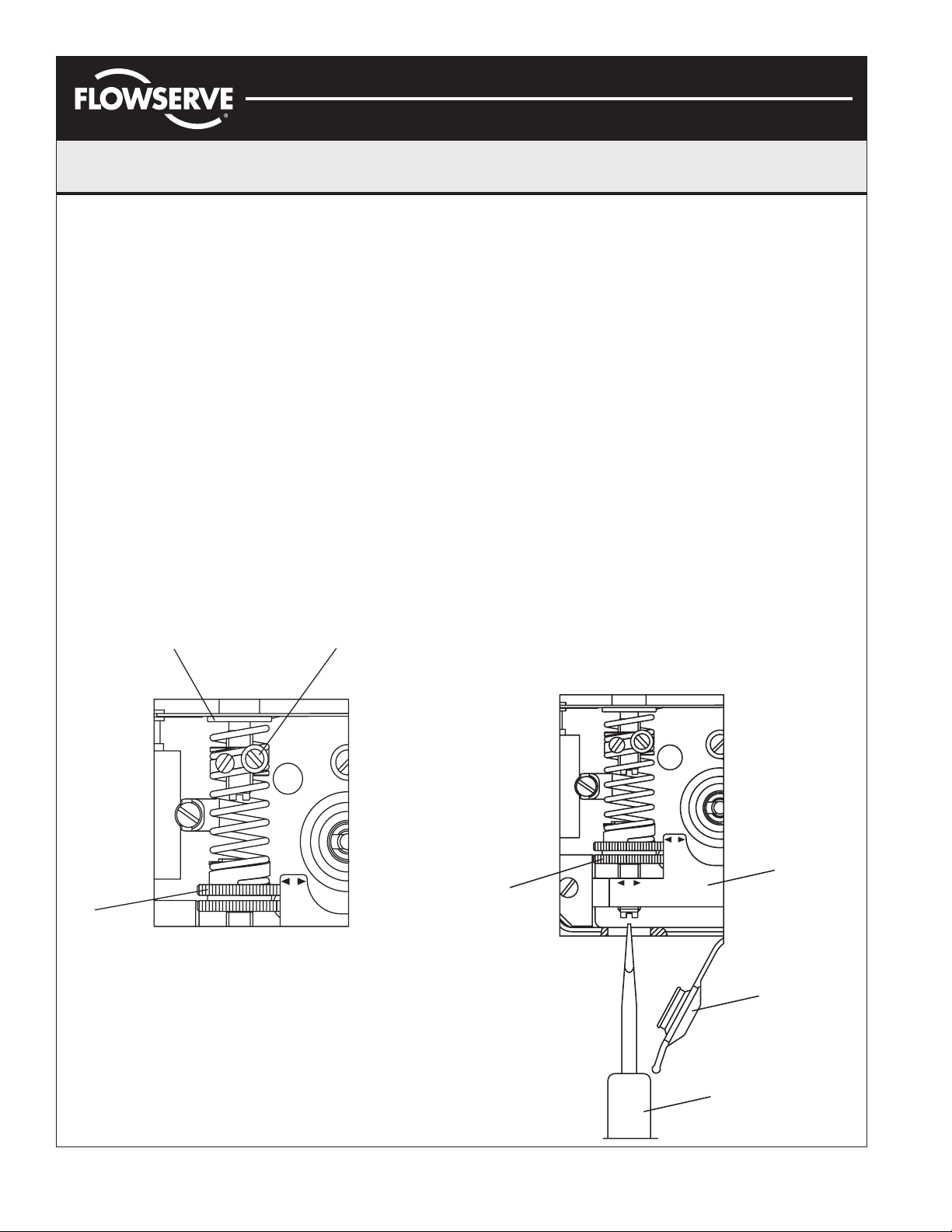
Calibration:
The unit is shipped from the factory pre-calibrated for 90
degree travel (±0.5 degrees rotation - can also be 30/45/
60 degrees, see installed cam). For most applications,
the valve closed position is much more critical than the
valve open position. Most attention should be made to
the valve closed position. Always start calibration
procedure by applying 0% input signal, then adjusting
zero position. The positioner is calibrated by turning
thumbwheels (1) and (4). Arrows on arm (5) indicate
turning direction of thumbwheels.
"+" = increase zero/span
▲
▼
"-" = decrease zero/span
Caution:
Cam pinch points may injure fingers. Be sure to
avoid placing fingers and other objects in cam pinch
points. Also avoid touching balance beam and spool
while making adjustments as unpredictable cam rotation
may result. Finally, maintain control of input signal while
making adjustments.
23
Calibration Procedure:
1. Apply O% input signal (0% = 20 kPa, 3 psi, or 4 mA).
2. Wait for steady state. It is important to wait for steady
state. On very large actuators, it can take minutes to
establish.
3. Adjust zero by turning the silver (lower) thumbwheel (4)
with finger or with screwdriver (7) from the outside.
4. Apply 100% input signal (100% = 100 kPa, 15 psi, or
20 mA).
5. Wait for steady state; remember result.
6. Apply 0% input signal.
7. Adjust span per result in step (5) above. This is
accomplished by first loosening screw (2), then turning
the yellow (upper) thumbwheel (1) in appropriate
direction with finger. Tighten screw 2. Spring top must
not be in contact with spring guide (3).
8. Check and adjust zero.
9. Repeat steps 2 through 8 until desired calibration is
achieved.
+
1
Span Adjustment
AXAIMO36-00 (AUTO-112) 7/03
© 2003, Flowserve Corporation, Printed in USA
SPAN
+
-
SPAN
+
-
4
Zero
Adjustment
ZERO
-
5
6
7
Page 2 of 8
Page 3
Automax Valve Automation Systems
3-Position Control/Dribble Control
Installation, Operation and Maintenance Instructions
SR Limit Switch Method
Flowserve Corporation 1350 N. Mountain Springs Parkway 1978 Foreman Dr.
Flow Control Division Springville, Utah 84663-3004 Cookeville, TN 38501
www.flowserve.com Phone: 801 489 8611 Phone: 931 432 4021
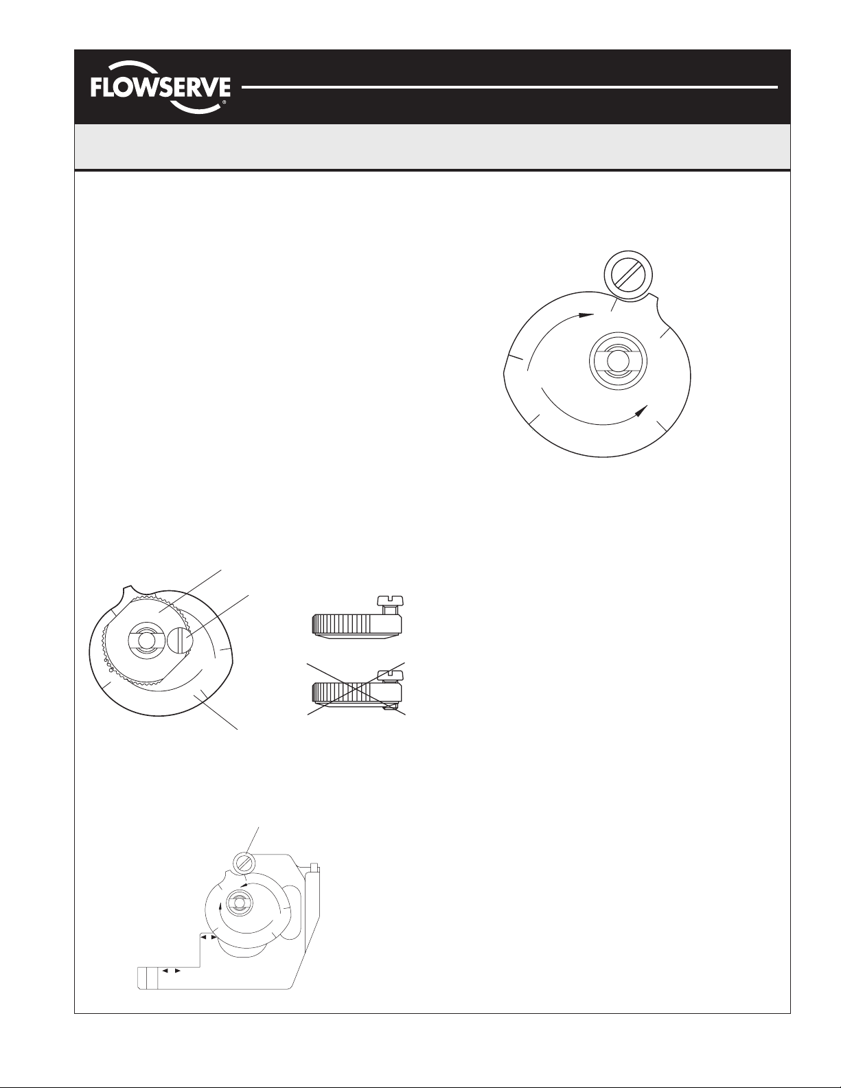
Cam Installation:
Introduction: The standard cam (labeled "K1") features
linear, 90 degree operation for full 3-15 psi input, 3-9
and 9-15 psi split ranges, and 3-15 psi 180 degree
operation. The factory setting is 3-15 psi, 90 degrees,
with “D” (direct) side up for full clockwise position at
3 psi for 90° operation.
Caution:
pressure exists in actuator before adjusting cam.
Cam Adjustment:
1. Remove cover and indicator.
2. Loosen the camlock screw (1) and turn the cam
3. Adjust the cam (3) as desired, making sure that the
4. Secure the cam by finger tightening the cam locking
Be sure supply air pressure is removed and no
locking nut (2) counterclockwise until the cam is
loose. It may be necessary to brace the output shaft
while loosening the cam locking nut.
cam follower (4) always rides on an active lobe on
the cam.
nut (2), and then tighten the camlock screw (1)
(see below).
%
0
E
G
N
A
%
R
0
5
N
I
L
0
%
S
P
L
I
T
1
˚
8
0
2
9
0
˚
L
I
N
K
1
%
1
1
0
0
%
Correct
1
0
0
Incorrect
3
Figure below shows cam setting for reverse action,
decreasing signal 100-0% (100-20 kPa, 15-3 psi) to open.
Flip cam over, cam follower to ride on lobe R, 0-100%.
0
%
N
I
L
˚
0
9
R
%
0
0
1
0
%
1
K
%
0
0
1
Split Range lobe is used to achieve high resolution in split
range applications, where only a portion of the signal is
used to obtain 90 degrees valve travel. For example, to
operate 0 to 90 degrees rotation with 0-50% input signal
(20-60 kPa, 3-9 psi), adjust cam follower to ride on Split
Range 0-50% lobe D. Note:
cam over and use lobe R.
D
˚
0
9
N
E
G
N
I
˚
L
0
To obtain reverse action, flip
S
P
L
I
T
R
5
A
0
%
1
8
Figure below shows cam setting for Direct Action
increasing signal 0-100% (20-100 kPa, 3-15 psi)
to open. Cam follower to ride on lobe D, 0-100%.
4
%
0
9
0
˚
L
I
N
1
0
0
%
K
1
1
0
0
%
S
A
P
R
L
I
T
N
I
L
˚
1
0
8
+
ZERO
%
0
˚
0
9
E
G
N
%
0
5
+
-
SPAN
-
AXAIMO36-00 (AUTO-112) 07/03
© 2003, Flowserve Corporation, Printed in USA
Page 3 of 8
Page 4

Automax Valve Automation Systems
I
3-Position Control/Dribble Control
Installation, Operation and Maintenance Instructions
SR Limit Switch Method
Flowserve Corporation 1350 N. Mountain Springs Parkway 1978 Foreman Dr.
Flow Control Division Springville, Utah 84663-3004 Cookeville, TN 38501
www.flowserve.com Phone: 801 489 8611 Phone: 931 432 4021
Spool Valve Installation:
To change out or inspect spool valve, air supply to the
positioner must be removed.
To remove spool valve:
1. Remove screw (1).
2. Carefully lift out entire spool valve assembly (2),
disengaging spool (3) from balance arm (5).
To maintain highest performance, do not mix spool
and block. Do not lubricate spool valve.
To install new spool valve:
1. Check that O-rings are in place.
2. Insert spool valve assembly (2), making sure that
the leaf spring (4) and balance arm (5) engage the
slot in the spool (6).
3. Tighten screw (1).
4. Check for smooth operation of assembly.
36
5
4
3
2
1
5
5
5
4
I-P Installation:
All I-P modules are factory calibrated and cannot be
adjusted. Kits are available to allow easy field installation of various input options. Kits include modules,
mounting hardware, fasteners, and O-rings.
1. Disconnect signal and supply air from positioner.
2. Remove screw (1) from positioner housing.
3. Make sure O-rings (2) are seated correctly in I-P
housing.
4. For weatherproof or intrinsically-safe I-P module,
remove cover (4) to allow access to third mounting screw (5).
5. Attach I-P module (3) to positioner housing with
three mounting screws (5) provided.
I/
3
2
1
I
"ZZ" 1/4"
C1
C2
S
SWEDEN
N
MADE I
29-145 Psi
˚F
:
Type:
no
:
Ser.
Input:
tput
u
O
C -40>>+185
Action:
Supply:0,2-1 MPa
p:-40>>+85˚
Tem
i
R
Ps
i<350
R
mA
kPa
P CONVERTE
AXAIMO36-00 (AUTO-112) 7/03
© 2003, Flowserve Corporation, Printed in USA
Page 4 of 8
Page 5

Automax Valve Automation Systems
3-Position Control/Dribble Control
Installation, Operation and Maintenance Instructions
Flowserve Corporation 1350 N. Mountain Springs Parkway 1978 Foreman Dr.
Flow Control Division Springville, Utah 84663-3004 Cookeville, TN 38501
www.flowserve.com Phone: 801 489 8611 Phone: 931 432 4021
SR Limit Switch Method
Electrical Specifications:
Max. Voltage Min. Voltage Max. Current
Model Agency Approvals Hazardous Location Rating
4000 None None NA NA NA
4100 None None 30 VDC 6 VDC 150 mA
4200
FM (EX) Cl. 1, Div. 1, Gr. B-D 30 VDC 6 VDC 150 mA
CSA (EX) Cl. 1, Div. 1, Gr. B-D 30 VDC 6 VDC 150 mA
4300 DMT (EX) EEx d IIC T4-T6
FM (IS) Cl. 1, Div. 1, Gr. A-D 28 VDC
4400
2
CSA (IS) Cl. 1, Div. 1, Gr. A-D 28 VDC
SCS (IS) Ex I 1 G EEx ia IIC T6
TÜV (IS) Ex II 2 G EEx ia IIC T6
Warning: These instruments must be installed in accordance with local and national electrical codes, especially for hazardous locations.
Consult unit label to determine specific unit certifications.
Notes:
1
See hazardous location certificate for detailed temperature ratings. All Apex 4000 units comply with ATEX directive for non-electric
equipment intended for use in hazardous locations to EX II 2 G.
2
Additional information regarding entity parameters and instructions for wiring to intrinsically-safe I-P may be found in separate IOM, as
well as in the hazardous location certificate.
3
See hazardous location certificate for special conditions for safe use.
4
Maximum voltage and current considerations may be affected by application specifics, such as choice of barrier, ambient temperatures,
etc. See hazardous location certificate for additional information.
Filter Plug Replacement:
Caution:
Do not operate the unit without filter and filter
plug installed. Do not attempt to unscrew filter plug while
positioner is pressurized.
Note:
This filter is not designed to act as a permanent
source of clean, dry air.
1
(VDC) (VDC) (mA)
3
3
3
30 VDC
30 VDC
28 VDC
4
4
4
4
4
6 VDC 50 mA
6 VDC 50 mA
6 VDC 50 mA
6 VDC 110 mA
6 VDC 60 mA
4
4
4
4
4
1. Remove air supply pressure from positioner.
2. Unscrew filter plug (1) and O-ring.
3. Remove filter (3) and inspect filter and filter compart-
ment. If moisture is found, check upstream filters and
oil-water separators. Moisture can cause I-P failure.
4. Replace filter if necessary and reinstall.
3
2
1
AXAIMO36-00 (AUTO-112) 07/03
© 2003, Flowserve Corporation, Printed in USA
Page 5 of 8
Page 6

Automax Valve Automation Systems
3-Position Control/Dribble Control
Installation, Operation and Maintenance Instructions
Flowserve Corporation 1350 N. Mountain Springs Parkway 1978 Foreman Dr.
Flow Control Division Springville, Utah 84663-3004 Cookeville, TN 38501
www.flowserve.com Phone: 801 489 8611 Phone: 931 432 4021
SR Limit Switch Method
Maintenance:
The Apex 4000 positioner is designed for long life and
trouble-free operation. The following steps should be followed
every six months to assure proper operation.
1. Check air supply and associated filtration
equipment. See “Supply Air Requirements.”
2. Make sure arms, bearings, and adjustment screws
move freely. Caution:
Moving parts to check
freedom with supply pressure connected will cause
rotation of cam. Be sure to keep fingers away from
cam pinch points.
disassemble and lubricate with a light, instrument
grade grease (Lubriplate MAG 1 or equivalent).
If parts do not move freely,
3. Check for smooth operation of the spool valve. If
it sticks or feels “gummy”, remove it and clean
both spool and valve bore with solvent. Make
sure both parts are clean and dry before
reinstalling. Do NOT apply grease to these parts.
4. Check for air leaks in air supply.
5. Refer to “Troubleshooting” sections if
maintenance does not cure a problem.
Troubleshooting:
Problem Probable Cause/Solution
Actuator/Valve won’t stroke or 1. Positioner ports are connected to wrong sides of actuator.
goes full stroke with no control: 2. Cam on wrong side (see “Cam Installation”).
3. Stuck arm or spool valve (see “Maintenance”).
4. Input signal problem.
Calibration Shifts: 1. Loose mounting hardware.
2. Loose cam locking nut.
3. Loose cam locking screw.
Excessive air consumption (other 1. Spool valve seals leaking or loose screws.
than normal exhaust of 10-30 scfh): 2. Air leak between positioner/actuator or within actuator.
3. If condition occurs at end of stroke only, calibration is incorrect.
Oscillation or hunting: 1. Air leak between positioner/actuator or within actuator.
2. Oversized spool valve (decrease size).
Sluggish or slow response: 1. Undersized spool valve (increase size or add volume boosters).
2. Tubing restriction (check supply between positioner/actuator).
3. Tubing too small (increase tubing size).
AXAIMO36-00 (AUTO-112) 7/03
© 2003, Flowserve Corporation, Printed in USA
Page 6 of 8
Page 7

Automax Valve Automation Systems
< >
+
-
ZERO
+
-
SPAN
I
0
5
G
E
%
8
1
I
L
N
0
P
A
T
R
0
I
L
9
N
S
K
1
0
0
0
%
1
1
%
0
%
0
9
0
0
%
L
I
N
3-Position Control/Dribble Control
Installation, Operation and Maintenance Instructions
SR Limit Switch Method
Flowserve Corporation 1350 N. Mountain Springs Parkway 1978 Foreman Dr.
Flow Control Division Springville, Utah 84663-3004 Cookeville, TN 38501
www.flowserve.com Phone: 801 489 8611 Phone: 931 432 4021
18
3
19
18
18
5
4
18
16
19
I
NPT 1/4"
C1
C2
4
14
18
18
10
15
%
1
S
< >
-
+
4
SPAN
-
+
ZERO
0
0
0
1
0
%
9
0
1
K
0
L
N
9
I
I
N
L
E
G
0
N
0
8
A
%
1
R
T
I
%
0
L
5
P
S
0
%
13
17
18
2
18
11
19
18
18
12
19
8
7
APEX 4000 Spare Parts List
Item Spare
No. Part # Description Qty
1 Housing 1
2 Front cover 1
3 Diaphragm cover incl. O-ring 1
4 Diaphragm 1
5 Diaphragm washer 2
6 Balance arm 1
7 Feedback spring assembly 1
8 Lower arm assembly 1
9 Rod 1
10 Tension spring 1
11 Lower arm guide 1
12 XK0213
13 Cam locking nut incl. screw 1
14 Cam follower 1
15 X01162
16 Output shaft 1
17 Indicator 1
18 XK0216* Screw set Set
19 XK0217* Seal and O-ring set NBR, Nitrile rubber Set
*Screw set and seal kit include components for I-P units also.
AXAIMO36-00 (AUTO-112) 07/03
© 2003, Flowserve Corporation, Printed in USA
+
Spool valve incl. O-rings 1
++
Cam 90°/180° Linear 0-100%,
split range 0-50-100% 1
9
N
E
D
E
W
S
N
I
DE
MA
+
Spool Valve Kits
XK0213 Low flow spool valve assembly (includes O-rings)
XK0218 High flow spool valve assembly (includes O-rings)
++
Cam Options
X01162 Standard linear 90˚/180˚/split range cam
X01163 Linear 30˚/45˚/60˚ cam
X01166 Characterized cam, square, equal percentage
X01167 Linear 60˚/120˚ butterfly valve cam
Page 7 of 8
Page 8
Automax Valve Automation Systems
PM
V
FM
SA
M
ADE
IN
S
W
EDEN
"ZZ"
1
/4
"
I
3-Position Control/Dribble Control
Installation, Operation and Maintenance Instructions
SR Limit Switch Method
Flowserve Corporation 1350 N. Mountain Springs Parkway 1978 Foreman Dr.
Flow Control Division Springville, Utah 84663-3004 Cookeville, TN 38501
www.flowserve.com Phone: 801 489 8611 Phone: 931 432 4021
1e
1f
1e
1e
1/3
V
PM
50
3
<
i
Psi
R
TER
VER
N
mA
kPa
I/P CO
29-145 Psi
:
ype:
o
T
u
Ser.n
Inp
Out
˚F
185
+
a
t:
P
M
t:
-40>>
-1
C
:
pu
˚
n
,2
o
i
85
:0
+
ly
ct
>
p
A
>
p
0
u
S
mp:-4
e
T
1e
1a/3a
1f
1e
1b
1e
1f
1c
1f
1d
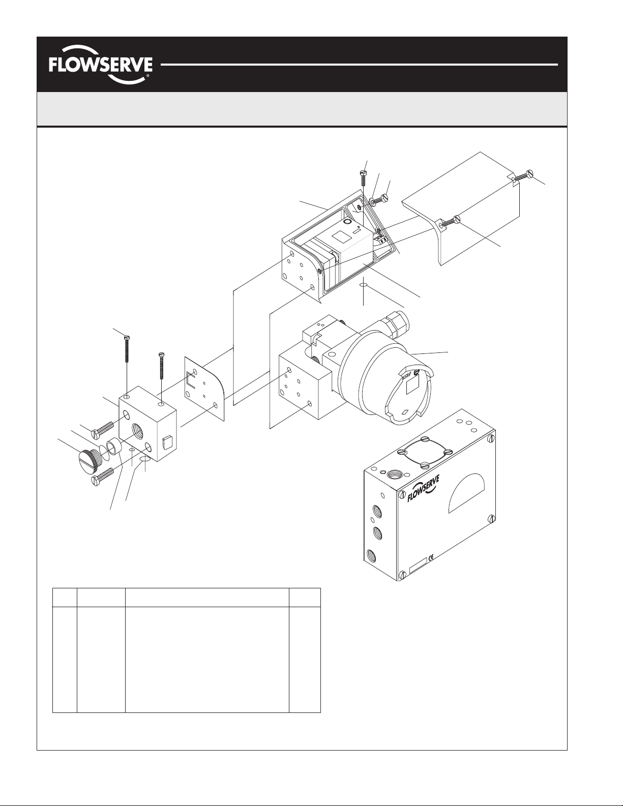
APEX 4000 I-P Spare Parts List
Item Spare
No. Part # Description Qty
1 KM41 General purpose I-P kit Kit
1a General purpose I-P module 1
1b I-P base block assembly (common) 1
1c I-P filter plug (common) 1
1d XK0219 I-P filter (common) 1
1e XK0216* Screw set (includes base 4000 components) Set
1f XK0217* Seal and O-ring set (includes base 4000 components) Set
2 KM42 Explosion-proof I-P kit Kit
2a Explosion-proof I-P module 1
3 KM44 Intrinsically-safe I-P kit Kit
3a Intrinsically-safe I-P module 1
*Note: KM kits do not include complete screw set and seal kit.
Complete screw sets and seal kits must be ordered separately.
2
CONVERTER
.
Type:
:
o
er.n
QUE
t:
S
ARE ALIVE
pu
TANT
In
:
t
E
M
tpu
SION.
ER
CIRCUITS
VDC
F
Ou
40
ILE
IEN
S TEN
WH
OU
F
HT
VOLTAGE:
TIG
hm
o
Supply pressure:
COVER
LES COUVERCLE B
mperature: 180
R=200
e
t
OPERATING
CIRCUITS SONT S
EEP
K
nt
e
LES
SA
GARDER
ambi
AXIMUM
C
1
M
um
IV
M
D
F
G
-
I,II
L
D
B
C
P
Maxim
VE
R
G
RO
1
PP
IV
A
D
G
I,II
B-
L
C
P
R
G
I
"ZZ" 1/4"
C1
C2
N
DE
S
E
W
S
IN
E
D
A
M
AXAIMO36-00 (AUTO-112) 7/03
© 2003, Flowserve Corporation, Printed in USA
Page 8 of 8
 Loading...