

Page 1
USER INSTRUCTIONS
Installation
3400MD Digital Positioner
FCD LGENIM3404-08 5/15
Operation
Maintenance
Experience In Motion
Page 2

Logix 3400MD Digital Positioner FCD LGENIM3404-08-AQ –5/15
2
Page 3

Contents
Logix 3400MD Digital Positioner FCD LGENIM3404-08-AQ – 5/15
1 Terms Concerning Safety 4
2 General Information 4
3 Unpacking and Storage 4
3.1 Unpacking 4
3.2 Storage 4
3.3 Pre-installation Inspection 5
4 Logix 3400MD Positioner Overview 6
4.1 Specifications 7
4.2 Positioner Operation 9
4.3 Detailed Sequence of Positioner Operations 10
5 Mounting and Installation 11
5.1 Mounting to Valtek Linear Mark One Valves 11
5.2 Mounting to Standard Valtek Rotary Valves
(See Figure 4) 11
5.3 Optional Valtek Rotary Mounting Procedure
(See Figure 5) 13
6 Wiring and Grounding Guidelines (See Figure 6) 14
6.1 FF Command Input Wiring 14
6.2 Grounding Screw 14
6.3 Segment Compliance Voltage
(See Figure 7) 15
6.4 Cable Requirements 15
6.5 Intrinsically Safe Barriers 15
6.6 DD Support 15
7 Startup 15
7.1 Logix 3400MD Local Interface Operation 15
7.2 Initial DIP Switch Settings 16
7.3 Description of Configuration DIP Switch Settings 16
7.4 Description of Cal DIP Switch Settings 17
7.5 RE-CAL Operation 17
7.6 Manual Jog Calibration Operation 18
7.7 Local Control of Valve Position 18
7.8 Factory Reset 18
7.10 Version Number Checking 20
7.11 475 Handheld Communicator 20
7.12 Device Description (DD) Files 20
7.13 Calibration 20
7.13.1 CALIBRATE_FLAGS 20
7.13.2 Control and Tuning 21
7.14 Alerts 21
7.14.1 FINAL_VALUE_CUTOFF 21
7.14.2 Effects of FINAL_VALUE_CUTOFF on Operation 22
7.14.3 Soft Limits 22
7.14.4 Travel Accumulator 22
7.14.5 Cycle Counter 22
7.14.6 Position Deviation 22
7.14.7 Advanced and Features 22
7.14.8 Standard vs. Advanced Diagnostics 22
7.14.9 Temperature and Pressure Units 22
7.14.10 Stroke Length 22
7.15 Characterization Retention 23
7.15.1 Initiating a Valve Signature 23
7.15.2 System Preparation 23
7.15.3 Signature Procedure 24
7.16 Step Signature 24
7.16.1 Collection of Stored Signature 24
7.17 Glossary 24
8 Maintenance and Repair 31
8.1 Driver Module Assembly 31
8.2 Regulator 33
8.3 Checking or Setting Internal 34
8.4 Spool Valve 34
8.5 Spool Valve Cover 35
8.6 Stem Position Sensor 36
8.7 Main PCB Assembly 36
8.8 Pressure Sensor Board 37
8.9 User Interface Board 38
9 Optional Vented Design 38
10 Parts List 40
11 Logix 3400MD Spare Parts Kits
(See Figure 22 for item numbers.) 40
12 Logix 3400MD Mounting Kits 41
12.1 Valtek Mounting Kits 41
12.2 Logix O.E.M. Mounting Kits 42
12.3 NAMUR Accessory Mounting Kit Part Numbers 42
13 Frequently Asked Questions 43
14 How to Order 44
15 Troubleshooting 45
flowserve.com
3
Page 4

Logix 3400MD Digital Positioner FCD LGENIM3404-08-AQ –5/15
1 Terms Concerning Safety
The safety terms DANGER, CAUTION and NOTE are used in these
instructions to highlight particular dangers and/or to provide
additional information on aspects that may not be readily apparent.
DANGER: Indicates that death, severe personal injury and/or
c
substantial property damage will occur if proper precautions are
not taken.
CAUTION: Indicates that minor personal injury and/or property
a
damage can occur if proper precautions are not taken.
NOTE: Indicates and provides additional technical information, which
may not be obvious even to qualified personnel. Compliance with all
other notes, even those not particularly emphasized, with regard to
transport, assembly, operation and maintenance and with regard to
technical documentation (e.g., in the operating instruction, product
documentation or on the product itself) is essential, in order to avoid
problems, which in themselves might directly or indirectly cause
severe personal injury or property damage.
2 General Information
The following instructions are designed to assist in unpacking,
installing and performing maintenance as required on Flowserve
Valtek Logix
used for all the positioners herein; however, specific numbers
indicate features specific to model (i.e., Logix 3400 indicates that the
positioner has Foundation Fieldbus protocol). See Logix 3400MD
Model Number table in this manual for a breakdown of specific model
numbers. Product users and maintenance personnel should thoroughly
review this bulletin prior to installing, operating, or performing any
maintenance on the valve.
Separate Valtek Flow Control Products Installation, Operation,
Maintenance instructions cover the valve (such as IOM 1 or IOM 27)
and actuator (such as IOM 2 or IOM 31) portions of the system and
other accessories. Refer to the appropriate instructions when this
information is needed.
To avoid possible injury to personnel or damage to valve parts,
WARNING and CAUTION notes must be strictly followed. Modifying
this product, substituting non-factory parts or using maintenance
procedures other than outlined could drastically affect performance
and be hazardous to personnel and equipment, and may void existing
warranties.
®
3400MD digital positioners. Series 3000 is the term
DANGER: Standard industry safety practices must be adhered to
c
when working on this or any process control product. Specifically,
personal protective and lifting devices must be used as warranted.
3 Unpacking and Storage
3.1 Unpacking
1. While unpacking the Logix 3400MD positioner, check the packing
list against the materials received. Lists describing the system
and accessories are included in each shipping container.
2. When lifting the system from the shipping container, position
lifting straps to avoid damage to mounted accessories. Systems
with valves up to six inches may be lifted by actuator lifting ring.
On larger systems, lift unit using lifting straps or hooks through
the yoke legs and outer end of body.
WARNING: When lifting a valve/actuator assembly with lifting
c
straps, be aware the center of gravity may be above the lifting
point. Therefore, support must be given to prevent the valve/
actuator from rotating. Failure to do so can cause serious injury
to personnel or damage to nearby equipment.
3. In the event of shipping damage, contact the shipper immediately.
4. Should any problems arise, contact a Flowserve Flow Control
representative.
3.2 Storage
Control valve packages (a control valve and its instrumentation) can
be safely stored in an enclosed building that affords environmental
protection; heating is not required. Control valve packages must be
stored on suitable skids, not directly on the floor. The storage location
must also be free from flooding, dust, dirt, etc.
Long-Term Storage of Logix 3000 Series Positioners in
Humid Locations
The Logix 3000 series positioners are designed to operate in humid
environments when connected to a proper instrument air supply.
There are some occasions when valves and positioners are stored
at job sites or installed and commissioned and then left without
instrument air for months. To make startup easier for units that are
left without instrument air and insure that the positioners will be
ready to operate, it is recommended that the vent assembly of the
positioner be sealed preferably with a desiccant pouch sealed with the
vent assembly.
4
Page 5
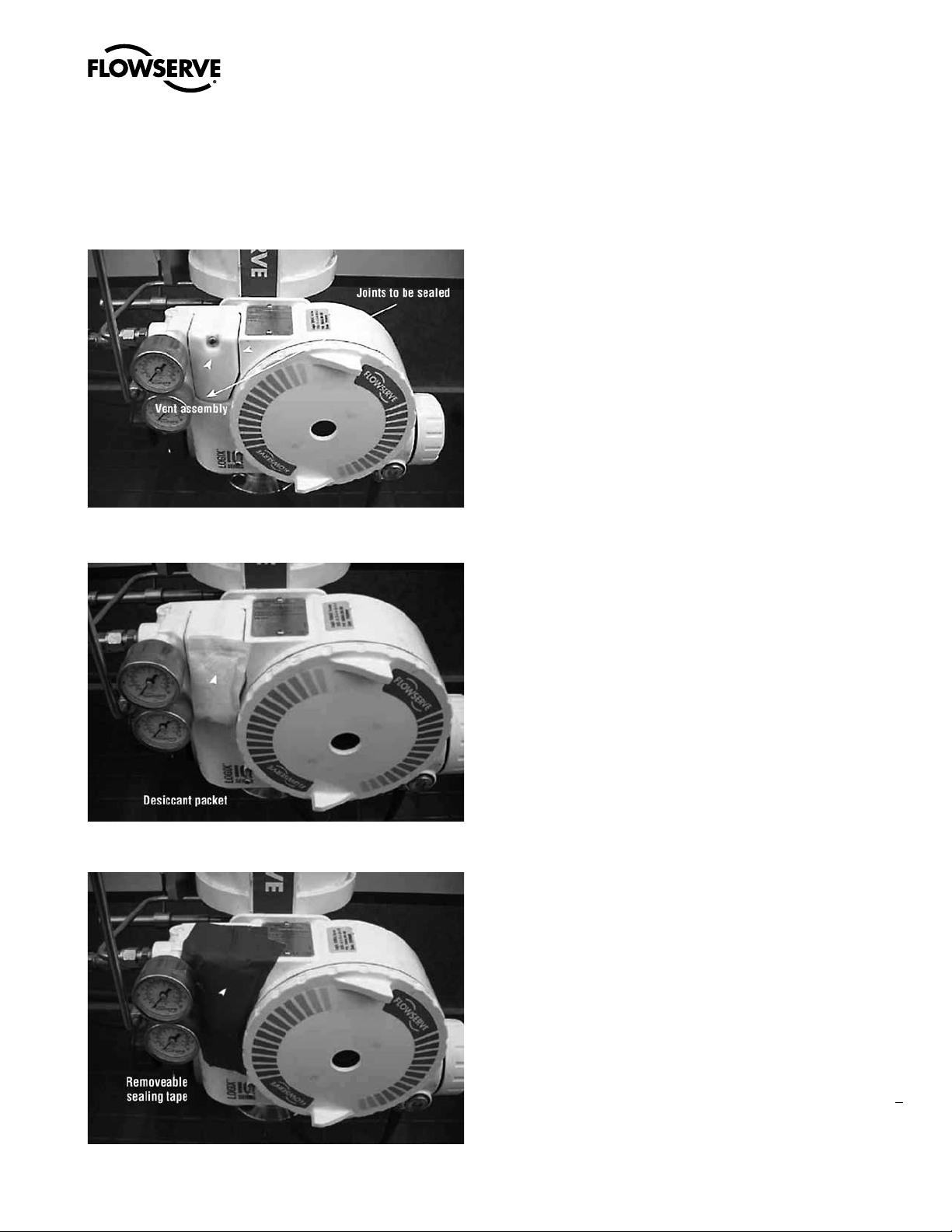
The vent assembly is located in the upper left side of the positioner.
The gaps around the assembly as noted by the arrows should be
sealed for long term storage
A small desiccant package as shown can be included under the
sealing tape to ensure proper protection.
Logix 3400MD Digital Positioner FCD LGENIM3404-08-AQ – 5/15
3.3 Pre-installation Inspection
If a valve control package has been stored for more than one year,
inspect one actuator by disassembling it per the appropriate Installation, Operation, and Maintenance Instructions (IOM) prior to valve
installation. If O-rings are out-of-round, deteriorated, or both, they
must be replaced and the actuator rebuilt. All actuators must then
be disassembled and inspected. If the actuator O-rings are replaced,
complete the following steps:
1. Replace the pressure-balance plug O-rings.
2. Inspect the solenoid and positioner soft goods and replace
as necessary.
All of the edges around the vend assembly should be sealed similar to
the picture below.
The sealing tape and desiccant should be removed when instrument
air is permanently applied to the positioner.
5
flowserve.com
Page 6
Logix 3400MD Digital Positioner FCD LGENIM3404-08-AQ –5/15
4 Logix 3400MD Positioner Overview
The Logix 3400MD digital positioner is a two-wire Foundation
Fieldbus compliant digital valve positioner. The positioner is
configurable through the local user interface. The Logix 3400MD
utilizes the FF protocol to allow two-way remote communications
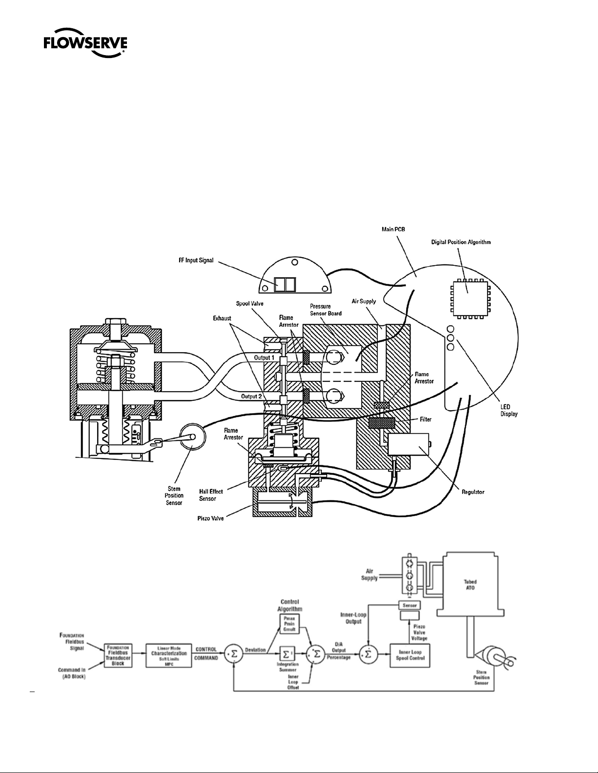
Figure 1: Logix 3400MD Digital Postioner Schematic (air-to-air open configuration)
with the positioner. The Logix 3400MD positioner can control both
double- and single- acting actuators with linear or rotary mountings.
The positioner is completely powered by the FF signal. Startup voltage
must be from a FF power supply source.
Figure 2: System Postioning Algorithm
6
Page 7
4.1 Specifications
Logix 3400MD Digital Positioner FCD LGENIM3404-08-AQ – 5/15
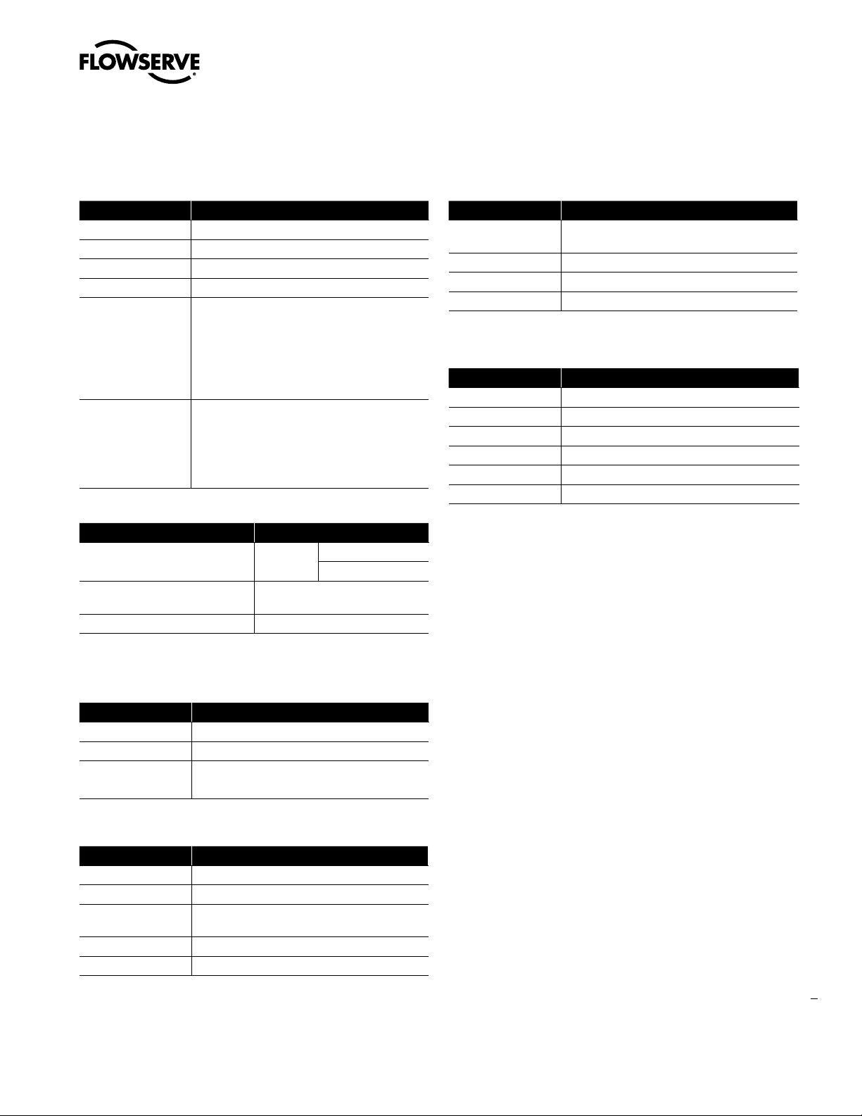
Table 1: Electrical Specifications
Item Description
Power Supply Two-wire, 9 to 32 V DC FF compatible
IS Fisco compliant
Communications FF Protocol ITK 5.1
Operating Current 18 mA
36.0 VDC
9 to 32 V DC for general use and flameproof
Voltage Limits
Wire
applications
9 to 24 V DC for Intrinsically safe applications
9 to 17.5 VDC for Intrinsically safe applications
per FISCO requirements
FF-844 FS1.2 H1 Cable Test Specifications
Terminal Lug 12-22 AWG. 0.27 in. max OD, 0.13
min ID.
Maximum Torque Rating: 7 in-lbs.
Table 2: Environmental Conditions
Item Description
Operating Temperature Range Standard
Transport and Storage
Temperature Range
Operating Humidity 0 – 100% non-condensing
*Note: The Logix 3400MD is designed to operate with clean, dry, oil-free instrument grade air per ISA
7.0.01-1996 or with dry nitrogen, sweet natural gas.
-40° to 185°F (-40° to 85°C)
-40° to 185° F
(-40° to 85°C)
Table 5: Air Supply Requirements
Item Description
Dew Point
Particulate Matter Filtered to 5 microns
Oil Content Less than 1 ppm w/w
Contaminants Free of all corrosive contaminants
At least 180°F (100°C) below minimum anticipated
ambient temperature
Table 6: Function Blocks
Item Description
AO One Analog Output
DI Two Discrete Inputs
DO One Discrete Output
PID One PID Control Function
OS One Output Splitter
IS One Input Selector
Table 3: Physical Specifications
Item Description
Housing Material Cast, powder-painted aluminum, stainless steel
Soft Goods Buna-N / Florosilicone
Weight
8.3 pounds (3.9 kg) aluminum
20.5 pounds (9.3 kg) stainless steel
Table 4: Positioner Specifications
Item Description
Deadband <0.1% Full Span
Repeatability <0.05% Full Span
Linearity
Air Consumption <0.3 SCFM (0.5 Nm3/hr) @ 60 psi (4 bar)
Air Supply 30-150 psig (ISA 7.0.0.1 compliant)
<0.5% (Rotary), <0.8%, (Linear Valve) Full Span
Per ISA 75.25.01-2000
7
flowserve.com
Page 8
Table 7: Hazardous Locations Information
ATEX
Flame Proof
FM07ATEX0005X
II 2 G
Ex d IIB+H2 T4/T6 Gb IP65
T4 Ta = -52˚C to +80˚C
T6 Ta = -52˚C to +60˚C
II 2 D
Ex tD A21 IP65 T95˚C Db
Ta = -52˚C to +55C
Intrinsically Safe
FM07ATEX0029X
II 1 G
Ex ia IIC T4/T6
T4 Ta = -40˚C to +80˚C
T6 Ta = -40˚C to +40˚C
Explosion Proof
IECEx FMG 11.0002X
Ex d IIB+H2 T4/T6 Gb IP65
T4 Ta = -52˚C to +80˚C
T6 Ta = -52˚C to +60˚C
Ex tb IIIC T95C Db
Ta = -52C to +55C
Intrinsically Safe
IECEx FME 07.0001X
Ex ia IIC T4/T6 Ga IP65
T4 Ta = -40˚C to +80˚C
T6 Ta = -40˚C to +40˚C
Entity Parameters
Fisco Field Device
Vmax = 24V
Imax = 380mA
Pi = 5.32W
Ci = 3.3nF
Li = 1uH
TR CU
Ex d IIB+H2 T4/T6 Gb IP65
Ex ia IIC T4/T6 Ga IP65
Ex nL nA IIC T6
T4 (Ta = -52˚C to +80˚C)
T6 (Ta = -52˚C to +60˚C)
Ex tb IIIC T95C Db IP65
Entity Parameters
Fisco Field Device
Vmax = 24V
Imax = 380mA
Pi = 5.32W
Ci = 3.3nF
Li = 1uH
IECEx
Gost
Logix 3400MD Digital Positioner FCD LGENIM3404-08-AQ –5/15
North America (FM/CSA)
Explosion Proof
Class I, Div 1, Groups B,C,D T6
DIP Class II, III, Div 1 Groups E,F,G T6
T6 Ta = -40˚C to +60˚C (FM US)
T4 Ta = -55˚C to +80˚C (CSA)
T5 Ta = -55˚C to +60˚C (CSA)
Type 4/4X IP65
Class 1, Zone 1, AEx d IIB+H2 T6 (FM US)
T6 Ta = -40˚C to +60˚C (FM US)
Type 4/4X IP65
Class 1, Zone 1, Ex d IIB+H2 T4/T6 (CSA)
T4 Ta = -55˚C to +80˚C
T6 Ta = -55˚C to +60˚C
Type 4/4X IP65
Intrinsically Safe
Class I,II, III, Div 1, Groups A,B,C,D,E,F,G T4/T6
Class I, Zone 0, AExia IIC T4/T6 (FM US)
Class I, Zone 0, Ex ia IIC T4/T6 (CSA)
T4 (Ta = -40˚C to +80˚C)
T6 (Ta = -40˚C to +40˚C)
Type 4/4X IP65
Entity Parameters
Fisco Field Device
Vmax = 24V
Imax = 380mA
Pi = 5.32W
Ci = 3.3nF
Li = 1uH
InMetro
Explosion Proof
TÜV 12.0646
Ex d IIB+H2 T5 Gb IP65
Ta = -55˚C to +80˚C
Ex tb IIIC T95C Db IP65
Ta = -55C to +55C
Intrinsically Safe
TÜV 12.0605
Ex ia IIC T4 Ga IP65
T4 Ta = -40˚C to +60˚C
Entity Parameters
Fisco Field Device
Vmax = 24V
Imax = 380mA
Pi = 5.32W
Ci = 3.3nF
Li = 1uH
Special Conditions for Safe Use:
1. When used within a Zone 0 location, cast-aluminum (when Enclosure Option b = 0, 2, 3, 4,or 5) enclosures shall be installed in such manner as to prevent the possibility of sparks resulting from
friction or impact against the enclosure.
2. To prevent the risk of electrostatic sparking, the equipment’s mechanical pressure gauges shall be cleaned only with a damp cloth.
3. Using the box provided on the nameplate, the user shall permanently mark the protection type chosen for the specific installation. Once the type of protection has been marked it shall not be
changed.
4. Consult the manufacturer if dimensional information on the flameproof joints is necessary.
8
Page 9
Logix 3400MD Digital Positioner FCD LGENIM3404-08-AQ – 5/15
4.2 Positioner Operation
The Logix 3400MD positioner is an electric feedback instrument.
Figure 1 shows a Logix 3400MD positioner installed on a doubleacting linear actuator for air-to-open action.
The Logix 3400MD receives power from the two-wire, FF input signal.
This positioner utilizes FF communications for the command signal.
The command source can be accessed with the Rosemount 375
communicator or other host software.
0% is always defined as the valve closed position and 100% is always
defined as the valve open position. During stroke calibration, the
signals corresponding to 0% and 100% are defined.
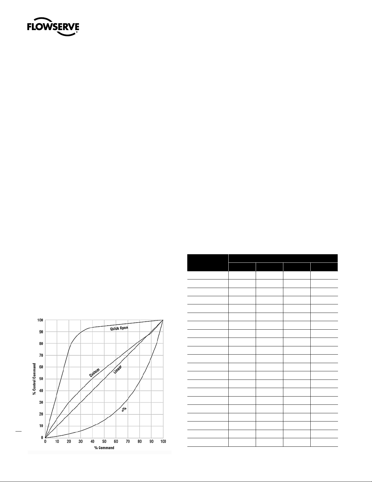
The input signal in percent passes through a characterization/
limits modifier block. The positioner no longer uses CAMs or other
mechanical means to characterize the output of the positioner. This
function is done in software, which allows for in-the-field customer
adjustment. The positioner has four basic modes: Linear, Equal
Percent (=%), Quick Open (QO) and Custom characterization. In
Linear mode, the input signal is passed straight through to the control
algorithm in a
1:1 transfer. In Equal Percent (=%) mode, the input signal is mapped
to a standard 30:1 rangeability =% curve. In Quick Open the input
signal is mapped to an industry standard quick-open curve. If Custom
characterization is enabled, the input signal is mapped to either a
default =% output curve or a custom, user-defined 21-point output
curve. The custom user-defined 21-point output curve is defined
using a handheld or the Host configuration tool software. In addition, two user-defined features, Soft Limits and Final Value Cutoff,
may affect the final input signal. The actual command being used to
position the stem, after any characterization or user limits have been
evaluated, is called the Control Command.
The Logix 3400MD uses a two-stage, stem-positioning algorithm. The
two stages consist of an inner-loop, spool control and an outer-loop,
stem position control. Referring again to Figure 1, a stem position
sensor provides a measurement of the stem movement. The Control
Command is compared against the Stem Position. If any deviation
exists, the control algorithm sends a signal to the inner-loop control
to move the spool up or down, depending upon the deviation. The
inner- loop then quickly adjusts the spool position. The actuator
pressures change and the stem begins to move. The stem movement
reduces the deviation between Control Command and Stem Position.
This process continues until the deviation goes to zero.
The inner-loop controls the position of the spool valve by means
of a driver module. The driver module consists of a temperaturecompensated Hall Effect sensor and a piezo valve pressure modulator.
The piezo valve pressure modulator controls the air pressure under
a diaphragm by means of a piezo beam bender. The piezo beam
deflects in response to an applied voltage from the inner-loop
electronics. As the voltage to the piezo valve increases, the piezo
beam bends, closing off against a nozzle causing the pressure under
the diaphragm to increase. As the pressure under the diaphragm
increases or decreases, the spool valve moves up or down respectively. The hall effect sensor transmits the position of the spool back
to the inner-loop electronics for control purposes.
Figure 3: Linear Mark OneTM Control Valve Mounting
9
flowserve.com
Page 10
Logix 3400MD Digital Positioner FCD LGENIM3404-08-AQ –5/15
4.3 Detailed Sequence of
Positioner Operations
A more detailed example explains the control function. Assume the
unit is configured as follows:
• Unit is in OOS.
• Custom characterization is disabled (therefore
characterization is Linear).
• No soft limits enabled. No Final Value Cutoff set.
• Valve has zero deviation with a present input command of 50.
• Write to Final_Value to change command.
• Actuator is tubed and positioner is configured air-to-open.
Given these conditions, 50 represents a Command source of 50
percent. Custom characterization is disabled so the Command source
is passed 1:1 to the Control Command. Since zero deviation exists,
the Stem Position is also at 50 percent. With the stem at the desired
position, the spool valve will be at a middle position that balances
the pressures above and below the piston in the actuator. This is
commonly called the null or balanced spool position.Assume the
input signal changes from 50 to 75. The positioner sees this as a
Command source of 75 percent. With Linear characterization, the
Control Command becomes 75 percent. Deviation is the difference
between Control Command and Stem Position : Deviation = 75% 50% = +25%, where 50 percent is the present stem position. With
this positive deviation, the control algorithm sends a signal to move to
spool up from its present position. As the spool moves up, the supply
air is applied to the bottom of the actuator and air is exhausted from
the top of the actuator. This new pressure differential causes the stem
to start moving towards the desired position of 75 percent. As the
stem moves, the Deviation begins to decrease. The control algorithm
begins to reduce the spool opening. This process continues until the
Deviation goes to zero. At this point, the spool will be back in its null
or balanced position. Stem movement will stop and the desired stem
position is now achieved.
One important parameter has not been discussed to this point: Inner
loop offset. Referring to Figure 2, a number called Inner loop offset
is added to the output of the control algorithm. In order for the spool
to remain in its null or balanced position, the control algorithm must
output a non-zero spool command. This is the purpose of the Inner
loop offset. The value of this number is equivalent to the signal that
must be sent to the spool position control to bring it to a null position
with zero deviation. This parameter is important for proper control
and is optimized and set automatically during stroke calibration.
10
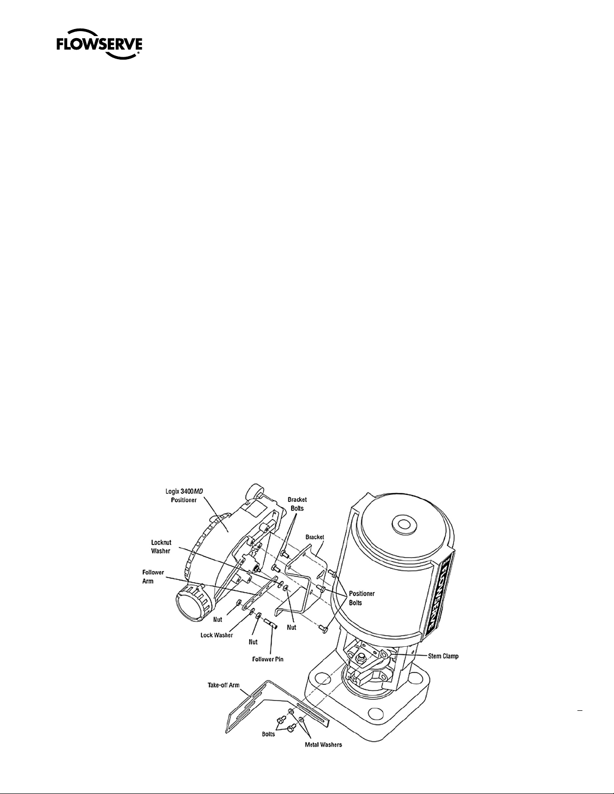
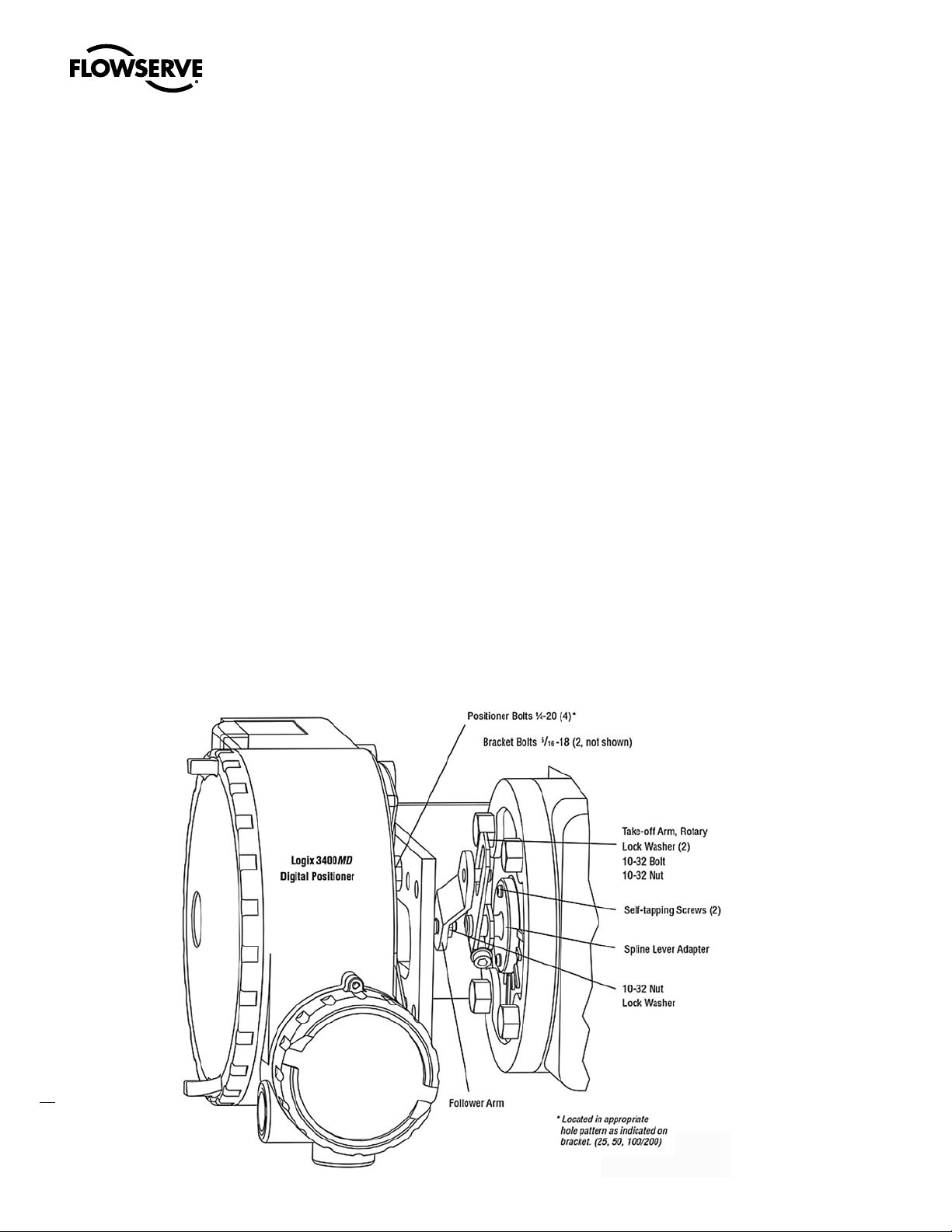
Figure 4: Standard Rotary Mounting
Page 11

Logix 3400MD Digital Positioner FCD LGENIM3404-08-AQ – 5/15
5 Mounting and Installation
5.1 Mounting to Valtek Linear
Mark One Valves
To mount a Logix 3400MD positioner to a Valtek linear Mark One
valve, refer to Figure 3 and proceed as outlined below. The following
tools are required:
9
•
⁄16” open-end wrench (or ½” for spud sizes 2.88 and smaller)
7
⁄16” box wrench
•
3
⁄8” open-end wrench
•
1. Remove washer and nut from follower pin assembly. Insert pin
into the appropriate hole in follower arm, based on stroke length.
The stroke lengths are stamped next to their corresponding holes
in the follower arms. Make sure the unthreaded end of the pin is
on the stamped side of the arm. Reinstall lock washer and tighten
nut to complete follower arm assembly.
2. Slide the double-D slot in the follower arm assembly over the
flats on the position feedback shaft in the back of the positioner.
Make sure the arm is pointing toward the customer interface side
of the positioner. Slide lock washer over the threads on the shaft
and tighten down the nut.
3. Align the bracket with the three outer mounting holes on the
positioner. Fasten with ¼” bolts.
4. Screw one mounting bolt into the hole on the yoke mounting pad
nearest the cylinder. Stop when the bolt is approximately 3⁄16”
from being flush with mounting pad.
5. Slip the large end of the teardrop shaped mounting hole in the
back of the positioner/bracket assembly over the mounting bolt.
Slide the small end of the teardrop under the mounting bolt and
align the lower mounting hole.
6. Insert the lower mounting bolt and tighten the bolting.
7. Position the take-off arm mounting slot against the stem clamp
mounting pad. Apply Loctite 222 to the take-off arm bolting and
insert through washers into stem clamp. Leave bolts loose.
8. Slide the appropriate pin slot of the take-off arm, based on stroke
length, over the follower arm pin. The appropriate stroke lengths
are stamped by each pin slot.
9. Center the take-off arm on the rolling sleeve of the follower pin.
10. Align the take-off arm with the top plane of the stem clamp and
tighten bolting. Torque to 120 in-lb.
NOTE: If mounted properly, the follower arm should be horizontal
when the valve is at 50% stroke and should move approximately
±30° from horizontal over the full stroke of the valve. If mounted
incorrectly, a stroke calibration error will occur and the indicator
lights will blink a YRYR or YRRY code indicating the position
sensor has gone out of range on one end of travel. Reposition the
feedback linkage or rotate the position sensor to correct the error.
5.2 Mounting to Standard Valtek
Rotary Valves (See Figure 4)
The standard rotary mounting applies to Valtek valve/actuator
assemblies that do not have mounted volume tanks or handwheels.
The standard mounting uses a linkage directly coupled to the valve
shaft. This linkage has been designed to allow for minimal misalignment between the positioner and the actuator. The tools required for
the following procedure are:
5
•
⁄32” Allen wrench
• ½” open-end wrench
7
⁄16” open-end wrench
•
3
⁄8” socket with extension
•
3
⁄16” nut driver
•
1. Fasten the spline lever adapter to the splined lever using two 6 x
½” self-tapping screws.
2. Slide the take-off arm assembly onto the spline lever adapter
shaft.Insert the screw with star washer through the take-off arm
and add the second star washer and nut. Tighten nut with socket
so arm is lightly snug on the shaft but still able to rotate. This will
be tightened after linkage is correctly oriented.
3. Attach follower arm to positioner feedback shaft using the star
washer and 10-32 nut.
NOTE: The arm will point up when feedback shaft is in the free
position.
4. Using four ¼-20 x ½” bolts, fasten positioner to universal bracket
using appropriate hole pattern (stamped on bracket).
5. Using a ½” end wrench and two
to actuator transfer case pad. Leave these bolts slightly loose
until final adjustments are made.
6. Rotate take-off arm so the follower pin will slide into the slot on
the take-off arm. Adjust the bracket position as needed noting
the engagement of the follower pin and the take-off arm slot. The
pin should extend approximately
properly adjusted, securely tighten the bracketing bolts.
5
⁄16-18 x ½” bolts, attach bracket
1
⁄16” past the take-off arm. When
11
flowserve.com
Page 12
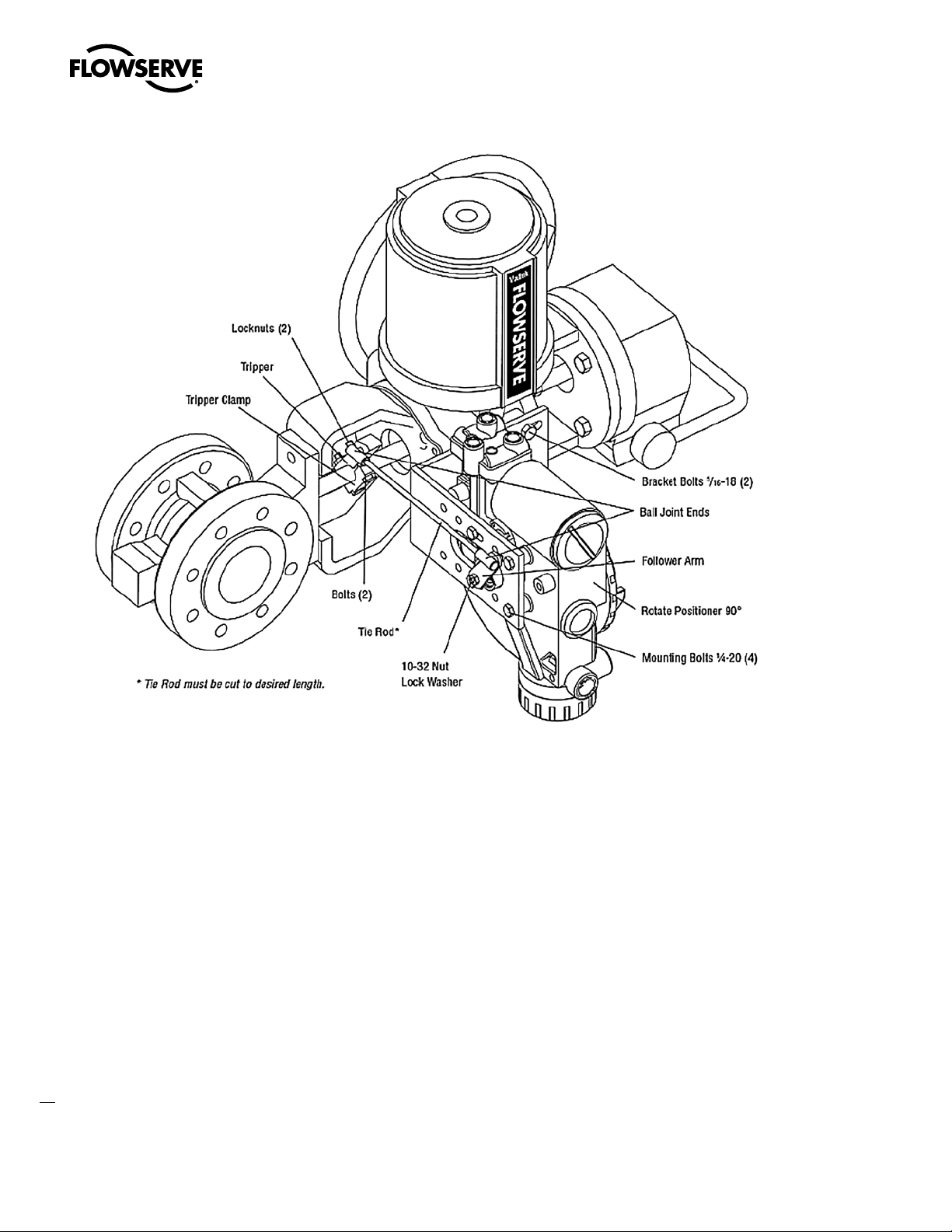
Figure 5: Optional Rotary Mounting
Logix 3400MD Digital Positioner FCD LGENIM3404-08-AQ –5/15
Orienting the Take-off Arm for Final Lock Down
1. Tube the Logix 3400MD positioner to the actuator according
to the instructions given in Section 5.5, “Tubing Positioner to
Actuator.”
2. With supply pressure off, rotate the follower arm in the same
direction the shaft would rotate upon a loss of supply pressure.
When the mechanical stop of the follower arm (positioner) is
reached, rotate back approximately 15 degrees.
3. Hold the take-off arm in place; tighten the screw of the take-off arm.
NOTE: The take-off arm should be snug enough to hold the
follower arm in place but allow movement when pushed.
4. Connect regulated air supply to appropriate port in manifold.
5. Remove main cover and locate DIP switches and RE-CAL button.
6. Refer to sticker on main board cover and set DIP switches accord-
12
ingly. (A more detailed explanation of the DIP switch settings is
given in Section 7, “Startup.”)
7. Press the RE-CAL button for three to four seconds or until the
positioner begins to move. The positioner will now perform a
stroke calibration.
8. If the calibration was successful the green LED will blink GGGG
or GGGY and the valve will be in control mode. Continue with
step 9. If calibration failed, as indicated by a YRYR or YRRY
blink code, the A/D feedback values were exceeded and the arm
must be adjusted away from the positioners limits. Return to
step 2 and rotate the arm back approximately 10 degrees.
NOTE: Remember to remove the air supply before re-adjusting
take-off arm.
9. Tighten the nut on the take-off arm. The socket head screw of
the take-off arm must be tight, about 40 in-lb.
NOTE: If the take-off arm slips, the positioner must be
recalibrated.
WARNING: Failure to follow this procedure will result in
c
positioner and/or linkage damage. Check air-action and stroke
carefully before lockdown of take-off arm to spline lever adapter.
Page 13

5.3 Optional Valtek Rotary Mounting
Procedure (See Figure 5)
The optional rotary mounting applies to Valtek valve/actuator
assemblies that are equipped with mounted volume tanks or
handwheels. The optional mounting uses a four-bar linkage coupled
to the valve shaft. The following tools are required:
3
•
⁄8” open-end wrench
7
⁄16” open-end wrench
•
• ½” open-end wrench
1. Using a ½” open-end wrench and two 5⁄16-18 x ½” bolts, attach
bracket to actuator transfer case pads. Leave bracket loose to
allow for adjustment.
2. Using four ¼-20 x ½” bolts and a
positioner to universal bracket, using the four-hole pattern
that locates the positioner the farthest from the valve. Rotate
positioner 90 degrees from normal so gauges are facing upward.
3. Attach follower arm to positioner feedback shaft, using the star
washer and 10-32 nut.
4. Attach tripper and tripper clamp to valve shaft using two ¼-20
bolts and two ¼-20 locknuts. Leave tripper loose on shaft until
final adjustment.
5. Thread ball joint linkage end to tripper and tighten (thread
locking compound such as Loctite is recommended to prevent
back threading). Adjust the length of tie rod so follower arm and
tripper rotate parallel to each other (the rod must be cut to the
desired length). Connect the other ball joint end to follower arm
using a star washer and a 10-32 nut.
6. Tighten bracket and tripper bolting.
7. Check for proper operation, note direction of rotation.
DANGER: If rotating in wrong direction, serious damage will
c
occur to the positioner and/or linkage. Check air action and stroke
direction carefully before initiating operation.
7
⁄16” open-end wrench, fasten
5.4 NAMUR Mounting Option
Logix 3200MD is available with a NAMUR output shaft and mounts
on an actuator using the ISO F05 holes. Proper alignment of the
positioner shaft to the actuator shaft is very important since improper
alignment can cause excess wear and friction to the positioner.
Logix 3400MD Digital Positioner FCD LGENIM3404-08-AQ – 5/15
5.5 Tubing Positioner to Actuator
The Logix 3400MD digital positioner is insensitive to supply pressure
changes and can handle supply pressures from 30 to 150 psig.
NOTE: A supply regulator is recommended if the customer will
be using the diagnostic features of the Logix 3400MD but is not
required. In applications where the supply pressure is higher than
the maximum actuator pressure rating a supply regulator is required
to lower the pressure to the actuator’s maximum rating (not to be
confused with operating range). An air filter is highly recommended
for all applications where dirty air is a possibility.
NOTE: The air supply must conform to ISA Standard ISA 7.0.01 (a
dew point at least 18°F below ambient temperature, particle size
below five microns—one micron recommended—and oil content not
to exceed one part per million).
Air-to-open and air-to-close are determined by the actuator
tubing, not the software. When air action selection is made during
configuration, that selection tells the control which way the actuator
has been tubed. The top output port is called Output 1. It should be
tubed to the side of the actuator that must receive air to begin the
correct action on increasing signal. Verify that tubing is correct prior
to a stroke calibration.
NOTE: Proper tubing orientation is critical for the positioner to
function correctly and have the proper failure mode. Refer to Figure 1
and follow the instructions below:
Linear Double-acting Actuators
For a linear air-to-open actuator, the Output 1 port of the positioner
manifold is tubed to the bottom side of the actuator. The Output 2
port of the positioner manifold is tubed to the top side of the actuator.
For a linear air-to-close actuator the above configuration is reversed.
Rotary Double-acting Actuators
For a rotary actuator, the Output 1 port of the positioner manifold
is tubed to the bottom side of the actuator. The Output 2 port of
the positioner manifold is tubed to the top side of the actuator. This
tubing convention is followed regardless of air action. On rotary
actuators, the transfer case orientation determines the air action.
Single-acting Actuators
For single-acting actuators, the Output 1 port is always tubed to the
pneumatic side of the actuator regardless of air action. The Output 2
port must be plugged.
flowserve.com
13
Page 14
Logix 3400MD Digital Positioner FCD LGENIM3404-08-AQ –5/15
6 Wiring and Grounding
Guidelines
DANGER: This product has electrical conduit connections in either
c
thread sizes ½” NPT or M20 which appear identical but are not
interchangeable. Housings with M20 threads are stamped with
the letters M20 above the conduit opening. Forcing dissimilar
threads together will damage equipment, cause personal injury
and void hazardous location certifications. Conduit fittings must
match equipment housing threads before installation. If threads
do not match, obtain suitable adapters or contact a Flowserve
representative.
DANGER Any unused cable entries are to be closed off with
c
appropriately certified blanking devices.
DANGER: When using cable glands, ensure that they are
c
appropriately certified.
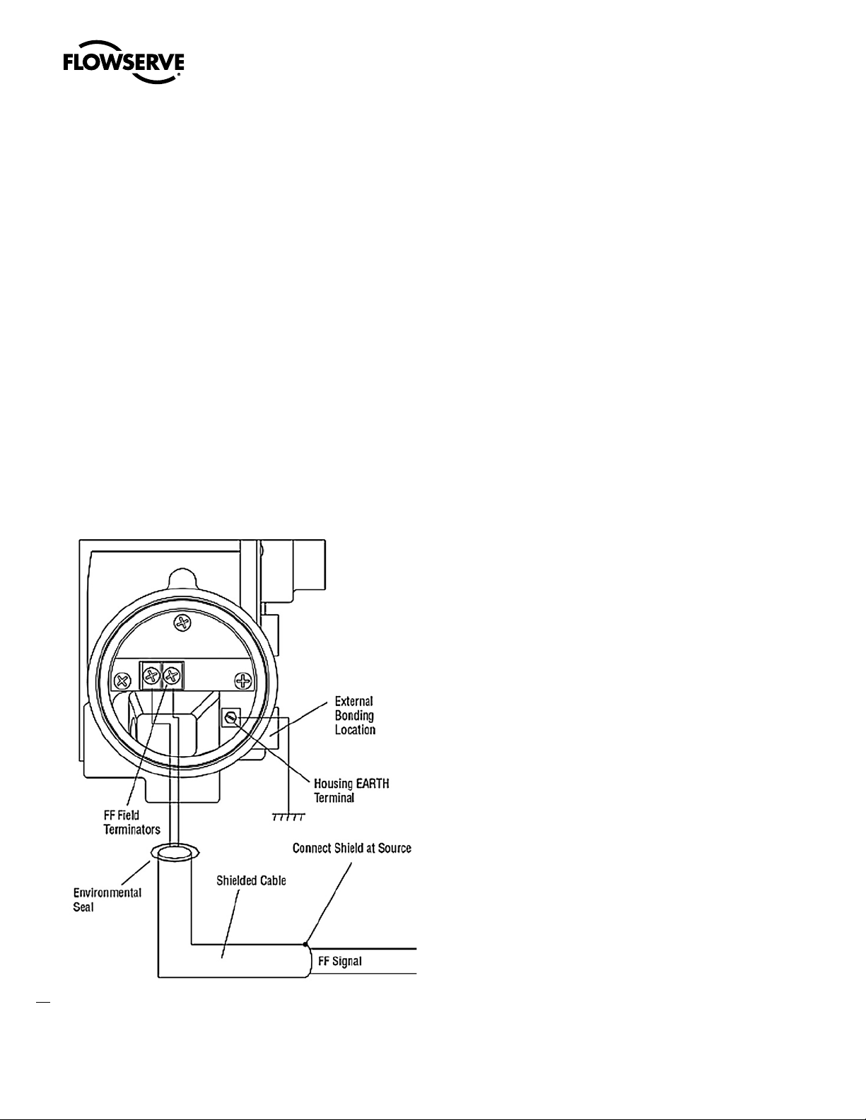
Figure 6: Field Termination
(See Figure 6)
6.1 FF Command Input Wiring
The Logix 3400MD is non-polarity sensitive. Wire FF source to the
input terminals (see Figure 6). Minimum operating voltage is 9 VDC.
The FF signal to the Logix 3400MD digital positioner should be in
shielded cable. Shields must be tied to a ground at only one end of
the cable to provide a place for environmental electrical noise to be
removed from the cable. In general, shield wire should be connected
at the source. Refer to guidelines in FF AG-140 and FF AG-181 for
proper wiring methods.
6.2 Grounding Screw
The green grounding screw, located inside the termination cap,
should be used to provide the unit with an adequate and reliable earth
ground reference. This ground should be tied to the same ground as
the electrical conduit. Additionally, the electrical conduit should be
earth grounded at both ends of its run.
DANGER: The green grounding screw must not be used to
c
terminate signal shield wires.
14
Page 15
Logix 3400MD Digital Positioner FCD LGENIM3404-08-AQ – 5/15
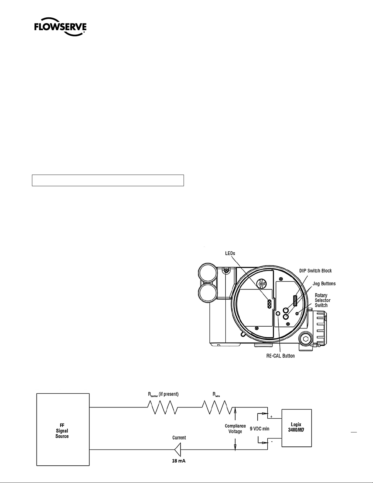
6.3 Segment Compliance Voltage
(See Figure 7)
Output compliance voltage refers to the voltage limit that can be
provided by the FF source. A FF system consists of the FF source,
wiring resistance, barrier resistance (if present), and the Logix
3400MD positioner voltage. The Logix 3400MD digital positioner
requires that the system allows for a 9.0 VDC drop across the
positioner at minimum segment voltage. The actual voltage at the
terminals varies from 9.0 to 32.0 VDC depending on the FF signal and
ambient temperature.
Determine if the segment will support the Logix 3400MD digital
positioner by performing the following calculation.
Equation 1
Voltage = Compliance Voltage (@ 18 mA) - 18 mA x (R
The calculated voltage must be greater than 9 VDC in order to safely
support the Logix 3400MD digital positioner.
Example:
DCS Compliance Voltage = 19 VDC
= 25 Ω
R
barrier
= 25 Ω
R
wire
Current
Voltage = 19 VDC – 0.018 A • (300 Ω + 25 Ω) = 13.15VDC
The voltage 13.15 VDC is greater than the required 9.0 VDC; there-
fore, this system will support the Logix 3400MD digital positioner.
= 18 mA
max
barrie
r + R
wire
)
6.6 DD Support
The DD for the Logix 3400MD can be downloaded from either the
Flowserve website: www.valvesight.com or the Foundation Fieldbus
website: www.Fieldbus.org.
7 Startup
7.1 Logix 3400MD Local Interface Operation
The Logix 3400MD local user interface (Figure 8) allows the user to
configure the basic operation of the positioner, tune the response,
and calibrate the positioner without additional tools or configurators.
The local interface consists of a RE-CAL button for automatic
zero and span setting, along with two jog buttons (
spanning valve/actuators with no fixed internal stop in the open
position. There is also a DIP switch block containing eight switches.
Six of the switches are for basic configuration settings and two are
for FF options. There is also a rotary selector switch for adjusting the
positioner gain settings. For indication of the operational status or
alarm conditions there are three LEDs on the local user interface.
Figure 8: Local User Interface
▲
and ▼) for
6.4 Cable Requirements
The Logix 3400MD digital positioner utilizes the FF protocol. This
communication signal is superimposed on the supply voltage.
FF rated cable should be used. Refer to H1 wiring specification (FF-844).
6.5 Intrinsically Safe Barriers
When selecting an intrinsically safe barrier, make sure the barrier is
FF compatible. Although the barrier will pass the segment voltage
and allow normal positioner operation, if not compatible, it may
prevent FF communication.
Figure 7: Compliance Voltage
15
flowserve.com
Page 16
Logix 3400MD Digital Positioner FCD LGENIM3404-08-AQ –5/15
7.2 Initial DIP Switch Settings
Before placing the unit in service, set the DIP switches in the Configuration boxes to the desired control options. A detailed description of
each DIP switch setting follows.
NOTE: The Logix 3400MD positioner reads the DIP switch settings
each time the RE-CAL button is pressed. If a FF handheld or Host
software is used to configure and then calibrate the positioner, the
DIP switches are not read. The auto-tune adjustment switch labeled
“GAIN” is always live and can be adjusted at any time.
Transducer block settings will always override the DIP switch settings
until the RE-CAL button is pressed.
7.3 Description of Configuration DIP
Switch Settings
The first six DIP switches are for basic configuration. The function
of each switch is described below.
Air Action
This must be set to match the configuration of the valve/actuator
mechanical tubing connection and spring location since these determine the air action of the system.
Pos. Characterization
Linear Select Linear if the actuator position should be directly
proportional to the input signal.
Other Select Other if another characteristic is desired, which is set in
conjunction with the Control_Flags parameter in the transducer block.
Optional Pos. Characterization
If the Pos. Characterization switch is set to Other then the CURVE_
SELECT parameter is active with the following options:
=% The =% option will characterize the actuator response to the
input signal based on a standard 30:1 equal percent rangeability
curve.
QO Quick open is based on a standard industry quick-open curve.
Custom If Custom is selected, the positioner will be characterized
to a custom table that must be set-up using a properly configured
475 handheld or other host software. Custom characterization can
be thought of as a “soft CAM.” The user can define a characterization
curve using 21 points. The control will linearly interpolate between
points. Points do not have to be equally spaced in order to allow more
definition at critical curve areas. The default values will linearize the
output of a valve with an inherent =% characteristic (e.g. ball valves.)
ATO (air-to-open)
Selecting ATC if increasing output pressure from the positioner is
tubed so it will cause the valve to close.
ATC (air-to-close)
Selecting ATC if increasing output pressure from the positioner is
tubed so it will cause the valve to close.
Figure 9: Default Custom Characterization
16
Table 8: Characteristic Curve Data
% Command
0 0 0 0 0
5 0.62 5 8.66 18.8
10 1.35 10 16.24 37.6
15 2.22 15 23.17 56.4
20 3.25 20 30.11 74.0
25 4.47 25 35.31 84.3
30 5.91 30 40.51 90.0
35 7.63 35 45.42 92.0
40 9.66 40 50.34 93.4
45 12.07 45 54.40 94.2
50 14.92 50 58.47 94.8
55 18.31 55 62.39 95.5
60 22.32 60 66.31 96.0
65 27.08 65 70.27 96.5
70 32.71 70 74.23 97.0
75 39.40 75 78.17 97.5
80 47.32 80 82.11 98.0
85 56.71 85 85.50 98.5
90 67.84 90 88.89 99.0
95 81.03 95 94.45 99.5
100 100.00 100 100.00 100.0
=% Linear Custom QO
% Control Command
Page 17

Logix 3400MD Digital Positioner FCD LGENIM3404-08-AQ – 5/15
Auto Tune
This switch controls whether the positioner will auto tune itself every
time the RE-CAL button is pressed or use preset tuning parameters.
On On enables an auto tune feature that will automatically determine
the positioner gain settings based on the current position of the
adjust- able GAIN switch setting and response parameters measured
during the last RE-CAL. The GAIN switch is live, meaning the settings
can be adjusted at any time by changing the rotary switch position.
(Note that there is a small black arrow indicating the selection. The
slot in the switch is NOT the indicator.)
Figure 10: Adjustable GAIN Switch
If the adjustable GAIN selector switch is set to “E” with the auto
tune switch on, a Flowserve standard response tuning set will be
calculated and used based on response parameters measured during
the last RE-CAL.
High-friction Valves Placing the switch to the right optimizes the
response for valves and actuators with high friction levels. This
setting slightly slows the response and will normally stop limit cycling
that can occur on high-friction valves.
7.4 Description of Cal DIP Switch Settings
The sixth DIP switch selects between two calibration options. The
function of the Cal DIP switch is described below.
NOTE: The unit must be in OOS mode before a calibration sequence
can begin.
Auto Select Auto if the valve/actuator assembly has an internal stop
in the open position. In Auto mode the positioner will fully close the
valve and register the 0% position and then open the valve to the stop
to register the 100% position when performing a self-calibration. See
detailed instructions in the next section on how to perform an auto
positioner calibration.
Jog Select Jog if the valve/actuator assembly has no physical
calibration stop in the open position. In the Jog mode the positioner
will fully close the valve for the 0% position and then wait for the user
to set the open position using the Jog buttons labeled with the up and
down arrows. See the detailed instructions in Section 7.6 on how to
perform a manual calibration using the Jog buttons.
DANGER: During the RE-CAL operation the valve may stroke
c
unexpectedly. Notify proper personnel that the valve will stroke,
and make sure the valve is properly isolated.
If the adjustable GAIN selector switch is set to “F”, “G”, or “H” with
the auto tune switch on, progressively higher gain settings will be
calculated and used based on response parameters measured during
the last RE-CAL.
Off Off forces the positioner to use one of the factory preset tuning
sets determined by the adjustable GAIN selector switch. Settings “A”
through “H” are progressively higher gain predefined tuning sets. The
GAIN selector switch is live and can be adjusted at any time to modify
the tuning parameters.
NOTE: “E” is the default adjustable GAIN selector switch setting for
all actuator sizes. Raising or lowering the gain setting is a function of
the positioner/valve response to the control signal, and is not actuator
size dependent.
Stability Switch
This switch adjusts the position control algorithm of the positioner for
use with low-friction control valves or high-friction automated valves.
Low-friction Valves Placing the switch to the left optimizes the
response for low-friction, high-performance control valves. This
setting provides for optimum response times when used with most
low-friction control valves.
7.5 RE-CAL Operation
NOTE: The unit must be in OOS mode before a calibration sequence
can begin.
The RE-CAL button is used to locally initiate a calibration of the
positioner. Pressing and holding the RE-CAL button for approximately
three seconds will initiate the calibration. If the Config-Switches
option is enabled, the settings of all the configuration switches are
read and the operation of the positioner adjusted accordingly. A
RE-CAL can be aborted at any time by briefly pressing the RE-CAL
button and the previous settings will be retained.
If the Quick Calibration switch (be careful not to confuse this with the
RE-CAL button) is set to Auto and the valve/actuator assembly has
the necessary internal stops the calibration will complete automatically. While the calibration is in progress you will notice a series of
different lights flashing indicating the calibration progress. When
the lights return to a sequence that starts with a green light the
calibration is complete. An explanation of the various light sequences
follows. The initial calibration of extremely large or small actuators
may require several calibration attempts. The positioner adapts to
the actuator performance and begins each calibration where the last
attempt ended. On an initial installation it is recommended that after
the first successful calibration that one more calibration be completed
for optimum performance.
17
flowserve.com
Page 18

Logix 3400MD Digital Positioner FCD LGENIM3404-08-AQ –5/15
DANGER: When operating using RE-CAL or local control, the valve
c
will not respond to external commands. Notify proper personnel
that the valve will not respond to remote command changes, and
make sure the valve is properly isolated.
7.6 Manual Jog Calibration Operation
If the Quick Calibration switch is set to Jog, the calibration will initially
close the valve then cause a small jump in the valve position. The jog
calibration process will only allow the user to manually set the span;
zero position is automatically always set at the seat. If an elevated
zero is needed a handheld or other PC-based configuration software
is required. When performing a jog calibration, the LEDs will flash in
a sequence of Y-G-Y-Y (yellow-green-yellow-yellow) which indicates
that the user must use the Jog buttons (
▲
and ▼) to manually
position the valve to the 100% position. When the stem is properly
positioned press both the Jog buttons (
▲
and ▼) simultaneously
again to register the 100% position and proceed. No more user
actions are required while the calibration process is completed.
When the lights return to a sequence that starts with a green light the
calibration is complete. An explanation of the various light sequences
follows.
7.7 Local Control of Valve Position
Local control of valve position can be achieved from the user
interface by holding down both Jog buttons and the RE-CAL button
simultaneously for three seconds. While in this mode the LEDs will
flash a Y-G-Y-Y (yellow- green-yellow-yellow) sequence. Use the
two Jog buttons (
▲
and ▼) to manually control the position of the
valve. To exit the local control mode and return to normal operation,
briefly press the RE-CAL button.
7.8 Factory Reset
To perform a factory reset, disconnect power, hold the RE-CAL button
down, and reconnect power. Performing a factory reset will cause all
of the internal variables, including calibration, to be reset to factory
defaults. The positioner must be recalibrated after a factory reset.
User configured limits, alarm settings, and valve information will also
need to be restored.
DANGER: Performing a factory reset may result in the inability
c
to operate the valve until reconfigured properly. Notify proper
personnel that the valve may stroke, and make sure the valve is
properly isolated.
Table 9: Status and Conditions
Error
Code Meaning
GGGG Normal Operation 255 1 Normal Operation
GGGY MPC Active 13 2
GGYG
GGYY
GGRR Squawk Mode 3 5 Squawk mode*
GYGG
GYGG
GYGY
GYGY
GRGG
GRGG
GRGG
GRGG
YGGY
YGGR Initializing 0 10
YGYG
YGYG
YGYG
YGYG
Local Interface
Disabled
Digital Command
Mode
Position Upper
Limit
Position Lower
Limit
Soft Stop Upper
Limit
Soft Stop Lower
Limit
Valve Cycles
Warning
Valve Travel
Warning
Spool Cycles
Warning
Spol Travel
Warning
Signature in
Progress
Stroke Cal in
Progress
Command Loop
Cal in Progress
Pressure Cal in
Progress
Analog Output
Cal in
Progress
Code
14 3
2 4
11
12
9
10
22
23
50
51
5 9
24
25
26
27
Sticker
Line
6
7
8
11
Sticker Text
Tight shutoff (MPC)
active*
Local Interface
Disabled*
Digital Command
mode*
Upper or lower
position alert*
Soft stop position
reached*
Travel or cycle limit
reached*
Signature in
progress
Initialization in
progress
Calibration in
progress
7.9 Logix 3400MD Status Condition
The blink codes used to convey the status of the Logix 3400MD
digital positioner are described in the table below. In general,
any sequence starting with a green light flashing first is a normal
18
operating mode and indicates that there are no internal problems. Any
sequence starting with a yellow light flashing indicates that the unit
is in a special calibration or test mode, or that there was a calibration
problem. Any sequence starting with a red light flashing indicates
that there is an operational problem with the unit.
YGYG
YGYY
YGYR
Setting Inner
Loop Offset
Joc Command
Mode
Jog Calibration
Set 100
Position
28
4 12
62 13
Local jog command
mode
Jog cal waiting ->
Set 100% pos.
Page 19

Table 9: Status and Conditions (continued)
Code Meaning
YYGG
YYGG
YYGY
YYGY
YYGY
YYGY
YYGR
Temp. High
Warning
Temp. Low
Warning
Port 1 Value Out
of Range
Port 2 Value Out
of Range
Port 1 Range Too
Small
Port 2 Range Too
Small
Supply Pressure
High
Warning
Error
Code
32
33
43
44
45
46
41 16
Sticker
Line
14
15
Sticker Text
Positioner
temperature warning
Pressure out of
range warning
Supply pressure
high warning* **
Logix 3400MD Digital Positioner FCD LGENIM3404-08-AQ – 5/15
Error
Code Meaning
RGYY
RGRR
RYYG
RRGG
RRGY
RRGR
RRYG
No Motion Time
Out
Factory Reset
State
Supply Pressure
Low Alarm
Spool Sticking
Alarm
Friction Low
Alarm
Friction High
Alarm
Piezo Voltage
Error
Sticker
Code
59 28
40 30
49 31
21 32 Friction low alarm*
20 33 Friction high alarm*
35 34
Line
1 29
Sticker Text
Feeback no motion
time
out alarm**
Factory reset state.
Recalibrate
Supply pressure low
alarm* **
Pilot relay response
alarm*
Piezo voltage
alarm***
YYYG
YYYY
YRGG
YRRY
YRRR
YRGY
YRGR
YRYG
RGGY
RGGY
Supply Pressure
Low Warning
Actuation Ratio
Warning
Spool Sticking
Warning
Electronic
Inability to Fail
Safe
Pneumatic
Inability to Fail
Safe
Friction Low
Warning
Pneumatic Leak
Warning
Friction High
Warning
Feedback Range
Too Small
Position Out of
Range 0
42 17
16 18
48 19
39 23
17 24
19 20
47 21
18 22
56
57
25
Supply pressure low
warning* **
Actuation ratio
warning* **
Pilot relay response
warning*
Electronic fail safe
warning
Pneumatic fail safe
warning
Friction low
warning*
Pneumatic leak
warning*
**
Friction high
warning*
Feedback calibration
range alarm
RRYR
RRYR
RRRY
RRRY
RRRY
RRRG
RRRR
*User Set
**Check Supply
***Circuit Board Problem; See IOM
Hall Sensor Upper
Position
Hall Sensor
Lower Position
Shunt Voltage
Reference Error
Watch Dog Time
Out
NV RAM
Checksum Error
Loss of Inter PCB
Comm
Position Deviation
Alarm
52
53
34
36
37
38 27
8 38
35
36
Pilot relay position
limit
alarm**
Electronics error
alarm***
Loss of board
communication***
Position deviation
alarm*
RGGY
RGGR
RGYG
Position Out of
Range 100
Inner Loop Offset
Time Out
Non Settle Time
Out
58
61 26
60 27
Inner loop offset
time out
alarm
Feedback non-settle
time
out alarm
19
flowserve.com
Page 20

Logix 3400MD Digital Positioner FCD LGENIM3404-08-AQ –5/15
7.10 Version Number Checking
1st Position: FF board firmware version number
nd
2
Position: Softing Stack version
rd
3
Position: Major version of command board
th
4
Position: Minor version of command board
7.11 475 Handheld Communicator
The Logix 3400MD Quick Start Guide is available from a Flowserve
representative.
The Logix 3400MD digital positioner supports and is supported by
the 475 Handheld Communicator. The Device Description (DD) files
and the manuals listed below can be obtained from the FF Foundation
or from your Flowserve representative. For more information please
see the following guides:
• Product Manual for the 475 Communicator
• Logix 3400MD Digital Positioner Reference Manual
Diagnostic features such as the signature tests and ramp tests are
performed internally. Certain calibration features such as actuator
pressure sensor calibrations are performed using the 475 Handheld
Communicator or using the Host software.
7.12 Device Description (DD) Files
The DD files for the Logix 3400MD can be downloaded from the
Flowserve website, http://www.valvesight.com, or the Foundation
Fieldbus website, www.fieldbus.org
Note: Position 1 and 2 are scaled by 100. This means that 210
translates to rev 2.10, etc.
Figure 11: Logix 3400 Block Diagram
7.13 Calibration
7.13.1 CALIBRATE_FLAGS
Perform a Stroke-Only Calibration
Selecting this option will cause only a stroke calibration to happen.
Automatically Calibrate Actuator and Pressure Sensors
Selecting this option will cause the 3400MD to perform all the
calibrations needed for the full diagnostic functionality of the 3420MD
Pro model. These include a stroke calibration, pressure sensor
calibration, and an actuator/valve friction calibration.
20
Page 21

Logix 3400MD Digital Positioner FCD LGENIM3404-08-AQ – 5/15
7.13.2 Control and Tuning
Setting P + I Parameters
Using the Host configurator, you can set individual tuning parameters.
A few key points are mentioned below (see Figure 11.)
GAIN_UPPER, GAIN_LOWER, and GAIN_MULT: These three
parameters are related by the following formula.
Proportional Gain = Maximum Gain - | deviation | x Gain Multiplier
If Proportional Gain < Minimum Gain, then Proportional Gain =
Minimum Gain
This algorithm allows for quicker response to smaller steps yet stable
control for large steps. Setting the gain multiplier to zero and max
gain = min gain results in a typical fixed proportional gain.
The higher the gain multiplier, the larger the required deviation before
the gain increases. Default values upon initiating a RESET to factory
defaults (under LOAD_EE_DEFAULTS) are maximum gain = 2.0,
minimum gain= 1.0, and gain multiplier= 0.05. These values will allow
stable control on all Valtek control product actuator sizes.
Integral Gain (IGAIN): The integral gain is primarily for deviations due
to temperature drift within the inner loop spool control. The factory
default value is 10. Although higher numbers can speed the time it
takes to reach zero deviation, it can add overshoot if too large. It is
recommended that maximum and minimum gains be adjusted while
leaving integral gain fixed at 10. Integration is disabled below a stem
position of 3 percent and above a stem position of 97 percent. This
is to prevent integration windup from calibration shifts due to lower
pressure or a damaged seat that may prevent fully closing the valve.
Integration Summer: The integral summer within the Logix 3400MD
digital positioner is clamped at +20 percent and -20 percent. If the
integration summer is fixed at +20 percent or -20 percent, it usually
indicates a control problem. Some reasons for a clamped integration
summer are listed below:
• Stroke calibration incorrect
• Any failure which prevents stem position movement: stuck spool,
handwheel override, low pressure
• Incorrect inner loop offset
• Loss of air supply on a fail in place actuator
Writing a zero to integral gain (IGAIN) will clear the integral summer.
The integral gain can then be returned to its original value.
if it becomes necessary to replace the driver module assembly or the
software RESET calibration constants has been performed, it may be
necessary to adjust this value. The method below should be used to
adjust inner-loop offset.
Or simply perform a new stroke calibration.
From the fieldbus configurator:
• Set transducer block to OOS
• Enable Diagnostic Variable access in TEST_MODE
• Send a 50 percent command
• Set integral to zero
• Locate the DAC_PERCENT
• Write this percentage value to IL_OFFSET
• Write original value to Integral
These tuning sets can be used to obtain initial values for Flowserve
products and comparable actuator sizes. The user may need to adjust
this tuning to achieve optimal performance for a particular application.
Table 10: Factory Tuning Sets
Mfg. Tuning Set
VFactory_A 1 2 0.05 10 25
VFactory_B 1 2.5 0.05 10 50
VFactory_C 2 3 0.05 10 100
Valtek
Kammer
Automax
VFactory_D 4 5 0.05 10 200
VFactory_E 4 7 0.05 10 300
Trooper 48 0.4 0.5 0.05 25 31
Trooper 49 3 4 0.05 10 77.5
Trooper 48 0.4 0.5 0.05 25 31
Trooper 49 3 4 0.05 10 77.5
R1 0.3 0.5 0.05 10 3 to 5
R2 1 1.5 0.05 10 9 to 12
R3 1.3 2 0.05 10 16 to 19
R4 2 2.5 0.05 10 27 to 37
R5 2.5 3.6 0.05 10 48 to 75
R6 4 5 0.05 10 109
Gain
Lower
Gain
Upper
Gain
Multi
lgain
Compa-
rable size
(in2)
Inner loop offset (IL_OFFSET): Three control numbers are summed
to drive the inner loop spool position control: proportional gain,
integral summer, and inner-loop offset.
Inner-loop offset is the parameter that holds the spool in the ‘null’
or ‘balance’ position with a control deviation of zero. This value is
written by the positioner during stroke calibration and is a function of
the mechanical and electrical spool sensing tolerances. However,
7.14 Alerts
7.14.1 FINAL_VALUE_CUTOFF
The FINAL_VALUE_CUTOFF or tight shutoff feature of the
Logix 3400MD digital positioner allows the user to control the level
at which the command signal causes full actuator saturation in the
closed or open position.
flowserve.com
21
Page 22

Logix 3400MD Digital Positioner FCD LGENIM3404-08-AQ –5/15
This feature can be used to guarantee actuator saturation in the
closed or open position or prevent throttling around the seat at small
command signal levels. To enable, use configuration to apply the
desired FINAL_VALUE_CUTOFF threshold.
NOTE: The positioner automatically adds a 1 percent hysteresis value
to the FINAL_VALUE_CUTOFF_LO setting to prevent jumping in and
out of saturation when the command is close to the setting
7.14.2 Effects of FINAL_VALUE_CUTOFF
on Operation
With the FINAL_VALUE_CUTOFF_LO set at 5 percent the positioner
will operate as follows: Assume that the present command signal is
at 50 percent. If the command signal is decreased, the positioner will
follow the command until it reaches 5 percent.
At 5 percent, full actuator saturation will occur. The actuator will
maintain full saturation below 5 percent command signal. Now, as
the command increases, the positioner will remain saturated until
the command reaches 6 percent (remember the 1 percent hysteresis
value added by the positioner). At this point, the stem position will
follow the command signal.
If the FINAL_VALUE_CUTOFF_LO is set to 3 percent but the valve will
not go below 10 percent, STOP_LO_POS may be enabled. The lower
soft limit must be less than or equal to 0 percent in order for the
FINAL_VALUE_CUTOFF_LO to become active.
If soft stops are active (ie: STOP_LO_POS = 0 or STOP_HI_POS =
100) FINAL_VALUE_CUTOFF is disabled.
7.14.3 Soft Limits
Unlike position alerts, soft limits prevent the stem position from
going below or above the configured limits. If the command signal is
trying to drive the position past one of the limits, the yellow LED will
blink but the stem position will remain at the set limit.
Percent present position plus 20 percent dead-band) and a low
travel threshold of 30 percent (50 percent present position minus 20
percent dead-band). As long as the stem position remains greater
than 30 percent and less than 70 percent, no additions are made to
the travel accumulator. Now, assume the stem position moves to 80
percent that is outside the present dead-band. The Logix 3400MD
digital positioner calculates the stem movement and adds this
number to the travel accumulator.
80 percent (present position) - 50 percent (previous) =
30 percent movement x 4-inch stroke = 1.2 inches
So, 1.2 inches is added to the travel accumulator. New dead-band
thresholds of 100 percent (80 percent present position plus 20
percent dead-band) and 60 percent (80 percent present position
minus 20 percent dead-band) are calculated. This process continues
as the stem position moves throughout its stroke range.
7.14.5 Cycle Counter
The cycle counter is another means of monitoring valve travel. Unlike
the travel accumulator, the stem position must do two things to count
as a cycle: exceed the cycle counter dead-band and change direction.
A cycle counter limit can also be written into the positioner. If this
limit is exceeded, the yellow LED will blink.
7.14.6 Position Deviation
If the stem position differs from the control command by a certain
amount for a given length of time, the yellow LED will blink to signify
excess deviation. The trip point and settling times are set from the
transducer function block.
7.14.7 Advanced and Features
NOTE: These features can be activated for full diagnostic functionality
of the system. These are contained in the transducer blocks. Refer to
the Installation and Reference Manual for a more detailed explanation.
7.14.4 Travel Accumulator
The travel accumulator is equivalent to a car odometer and sums the
total valve movement. Using the user defined stroke length and travel
dead-band, the Logix 3400MD digital positioner keeps a running
total of valve movement. When the positioner first powers up, high
and low dead-band limits are calculated around the present position.
When the stem position exceeds the travel dead-band, the movement
from the center of the deadband region to the new position is calculated and added to the travel accumulator. From this new position,
deadband high and low limits are again calculated.
Example: The Logix 3400MD digital positioner has a default deadband configuration of 20 percent. The valve has a 4 inch linear stroke.
When the valve first powers up, the command signal is 50 percent.
22
The unit will calculate a high travel threshold of 70 percent (50
7.14.8 Standard vs. Advanced Diagnostics
Advanced diagnostics models add top, bottom, and supply pressure
sensors. This allows for diagnostic functionalities such as loss of
pressure, advanced signatures, etc. Pro diagnostics adds the full
compliment of diagnostic features offered by the Logix 3400MD.
7.14.9 Temperature and Pressure Units
The desired temperature and pressure units can be set during configuration. Once set, all readings will be displayed in the desired units.
7.14.10 Stroke Length
Stroke length is used by the travel accumulator. When the stroke
length and units are set, the length is used to determine the total
travel accumulated. The travel accumulator will have the units
associated with stroke.
Page 23

Logix 3400MD Digital Positioner FCD LGENIM3404-08-AQ – 5/15
Example: Stroke length is set to four inches. If the valve is moved
from 0 percent to 100 percent, four inches will be added to the travel
accumulator. The travel accumulator units will be inches. If Stroke
length is 90 degrees for a rotary, the travel accumulator will now have
units of degree. A 0 percent to 100 percent stroke will add 90 to the
travel accumulator.
Table 11: Transducer Block Characterization Parameters
Parameter Description Value - Meaning Comments
MODE_BLK
CURVE_ SELECT
USER_ INTERFACE_ ACTIVE
CURVEX
CURVEY
The operating mode of the transducer
block
Selects the characterization curve type
when the DIP switch is set to ‘Other’.
This parameter is inactive when the DIP
switch is selected to ‘Linear’.
Software version of the physical DIP
switches. The parameters can be
changed either in the parameter or at
the device via the DIP switches.
Numeric X value array for custom point.
(1 x 21 array points)
Numeric Y value array for custom point.
(1 x 21 array points)
NOTE: Stroke length is for information only and is not used during
calibration.
Auto - Auto (target mode) The transducer block must be out of service
OOS - Out of Service
0 - Equal Percent
1 - Quick Open Sets the characterization to quick open mode.
2 - Custom
1 - Air Action
2 - Characterization Linear
3 - Rotary Actuator Gain
X-axis value for custom stroke
characterization point.
Range –10 to 110
Y-axis value for custom stroke
characterization point.
Range –10 to 110
before characterization can be edited or
changed.
Sets the characterization to equal percent
mode.
Sets the characterization to use the curve fit
parameters CURVEX and CURVEY.
Select 1=ATO or 0=ATC
Select 1=Linear or 0=Other
Three bits of the parameter reflect the value
selected on the Rotary Actuator Gan switch
as follows:
A=111, B=011, C=101, D=001
E=110, F=010, G=100, H=000
Pair each X-value with corresponding Y-value
to define the desired point. Values must be in
ascending (or equal) order.
7.15 Characterization Retention
Once a custom curve has been loaded into the Logix 3400MD digital
positioner’s memory it is retained in the EPROM until it is either edited
or replaced. Turning Custom Characterization Active on or off now
selects between a linear response (off), or the new custom curve (on).
If either of the other two factory curves is selected it will overwrite
the custom curve in RAM only. The custom user-defined curve will
automatically be activated again when the factory curve is deselected.
7.15.1 Initiating a Valve Signature
A feature of the Logix 3400MD positioner is the ability to capture and
store a valve diagnostic signature. A signature is the collected data
response of the valve to a predefined set of operating conditions.
This stored data can later be uploaded to the host system for analysis
of potential problems. By comparing a baseline signature, when
the valve is new, to subsequent signatures at later times, a rate of
change can be tracked which can help predict possible faults in the
valve before they happen. This is called ‘predictive maintenance’. It is
important to note
that the purpose of the positioner is to act as the data acquisition
device for the signature. Analysis of the data is not done on the
device, but in the supervisory system.
NOTE: Signature data is lost if the positioner is reset or if the power
is cycled.
7.15.2 System Preparation
DANGER: By definition, the collection of the signature requires
c
the unmanaged operation of the positioner. Therefore, the process
must be in a safe operating mode where unexpected movement of
the valve will not cause a hazardous condition.
Before a valve signature can be run, the Transducer Block must
Out-of-Service (OOS).
flowserve.com
23
Page 24

Logix 3400MD Digital Positioner FCD LGENIM3404-08-AQ –5/15
7.15.3 Signature Procedure
The following steps are an example of how to initiate a ramp
signature capture.
1. Make sure the process is in safe condition and notify the control
room that the valve will temporarily be taken off-line.
2. Verify preparedness to proceed.
3. Put the Transducer block MODE_BLK OOS.
4. Set SIG_START to desired value.
5. Set SIG_STOP to desired value.
6. Set SAMPLE_TIME to desired value (typically 0.3).
7. Set SIG_RATE to desired value (typically 20).
8. In SIG_FLAGS, select RUN_RAMP.
9. In SIG_FLAGS, select RUN/BEGIN_SIG.
10. Write values to the Logix 3400MD digital positioner.
11. The valve will stroke to the beginning position, as defined by SIG_
START and will begin ramping to the desired ending position, as
defined by SIG_STOP.
Notice that the valve will move and FINAL_POSITION_VALUE
will change.
12. SIG_FLAGS indicates SIG COMPLETE.
7.17 Glossary
A/D Also called ADC. Analog-to-digital converter. An A/D converts an
analog signal into an integer count. This integer count is then used by
the microcontroller to process sensor information such as position,
pressure, and temperature.
D/A Also called DAC. Digital-to-analog converter. A D/A converts an
integer count into an analog output signal. The D/A is used to take a
number from the microcontroller and command an external device
such as a pressure modulator.
DTM (Device Type Manager) Provides a GUI interface for the user
to easily view and analyze the status of the valve and positioner.
EEPROM (Electrically Erasable Programmable Read Only Memory)
A device that retains data even when power is lost. Electrically
erasable means that data can be changed. EEPROM have a limited
number of times data can be rewritten (typically 100,000 to 1,000,000
writes).
Micro-controller In addition to an integral CPU (microprocessor),
the micro-controller has built in memory and I/O functions such as
A/D and D/A.
Microprocessor Semiconductor device capable of performing
calculations, data transfer, and logic decisions. Also referred to as
CPU (Central Processing Unit).
Protocol A set of rules governing how communications messages
are sent and received.
13. Return the MODE_BLK to auto.
14. Notify control room the valve is back on-line. The stored
signature will remain in the Logix 3400MD digital positioner RAM
until the either the unit is powered down, or another signature is
taken which overwrites the previous one.
7.16 Step Signature
If a step signature was desired, simply do not select STEP_RAMP
in SIG_FLAGS, and then set the SIG_HOLD prior to selecting RUN/
BEGIN_SIG.
NOTE: SIG_RATE has no effect on Step Signature.
7.16.1 Collection of Stored Signature
The collection of the stored signature is accomplished by the host
system. It is not part of the device. See host system programming.
A simple utility using National Instruments NI-FBUS is available from
Flowserve for retrieving a signature file.
The parameters SIG_DATA1 – SIG_DATA26 can be populated with
24
the full signature data by writing a non-zero value to the SIG_INDEX
parameter.
Resolution Resolution is a number which indicates the smallest
measurement which can be made. You will often see analog-to-digital
(A/D) converters referred to as a 10-bit A/D or a 12-bit A/D. 10-bit
and 12-bit are terms which indicate the total number of integer counts
which can be used to measure a sensor or other input. To determine
the total integer count, raise 2 to the power of the number of bits.
Example: 12-bit A/D
Total integer number = 2
Number of Bits = 212= 4096
Resolution is the measurement range divided by the maximum
integer number. Example: A valve has a 2-inch stroke and a 12-bit
A/D is used to measure position. Resolution = Stroke/(Maximum
Integer for 12-bit) = 2 inch/4096 = 0.000488 inches Sampling Taking
readings at periodic time intervals.
Serial Channel Channel that carries serial transmission. Serial
transmission is a method of sending information from one device to
another. One bit is sent after another in a single stream.
The retrieved file is stored in a text format that can be imported into
other programs for plotting and analysis. Contact Flowserve for more
details.
Page 25

Logix 3400MD Digital Positioner FCD LGENIM3404-08-AQ – 5/15
Table 12: Transducer Block Parameters
Logix Positioner
Fieldbus
Block Index
0 BLK_DATA ALL RECORD N/A N/A N/A N/A SRW
1 ST_REV ALL UNSIGNED 16 N/A N/A N/A N/A SR
2 TAG_DESC ALL
3 STRATEGY ALL UNSIGNED 16 N/A N/A N/A N/A SRW
4 ALERT_KEY ALL UNSIGNED 8 N/A N/A N/A N/A SRW
5 MODE_BLK ALL RECORD N/A N/A N/A N/A SRW
6 BLOCK_ERR ALL BIT_STRING N/A N/A N/A N/A R
7 UPDATE_EVT ALL RECORD N/A N/A N/A N/A RW
8 BLOCK_ALM ALL RECORD N/A N/A N/A N/A RW
9
10
11 XD_ERROR ALL UNSIGNED 8 N/A N/A N/A N/A R
12
13 FINAL_VALUE
14 WORKING_SP
15
20
23
24
25
26 SPOOL_OFFSET
27
28
29
30 SPOOL_EFFORT
Fieldbus
Variable Name
TRANSDUCER_
DIRECTORY
TRANSDUCER_
TYPE
COLLECTION_
DIRECTORY
FINAL_POSI
TION VALUE
DEVIATION_
VALUE
DEVIATION_
EFFORT
PRESS_CTRL_
EFFORT
INTEGRAL_
EFFORT
SPOOL_
COMMAND
BACKOFF_
EFFORT
SPOOL_POSI
TION
Transducer
Block
ALL ARRAY N/A N/A N/A N/A NR
ALL UNSIGNED 16 N/A N/A N/A N/A NR
ALL ARRAY N/A N/A N/A N/A NR
XDTB_
MAIN
XDTB_
MAIN
-
XDTB_
MAIN
XDTB_
MAIN
XDTB_
TECH
XDTB_
TECH
XDTB_
TECH
XDTB_
TECH
XDTB_
TECH
XDTB_
TECH
-
XDTB_
TECH
XDTB_
TECH
Fieldbus
Datatypes
OCTET_
STRING
FLOAT_S 3 S_INT /100 CM_Digital NRW
FLOAT 7 S_INT /100
FLOAT_S 10 S_INT /100 FB_Pct NR
FLOAT 12 S_INT /100 Dev_Instant R
FLOAT 14 S_INT /100 Dev_Sum R
FLOAT 15 S_INT /100 PS_Sum R
FLOAT 16 S_INT /100 Integral_Sum R Control, DAC %, Integral Term
FLOAT 17 S_INT /100 IL_Offset RW
FLOAT 18 S_INT /100 IL_Cmd RW Control, DAC %, Total Effort
FLOAT 20 S_LONG NO Hall_Sum R
FLOAT 21 S_INT /100 Hall_Pct R
FLOAT 22 S_INT /100
Register Type
Fieldbus Standard Parameters
N/A N/A N/A N/A SRW
Control: Position Control Parameters
Fix
Pt
Rd
reserved for
spool effort
Variable
Name
CM_Pct_
Target
R/W
RW
R
Description
Foundation Fieldbus
Defined Parameter
Foundation Fieldbus
Defined Parameter
Foundation Fieldbus
Defined Parameter
Foundation Fieldbus
Defined Parameter
Foundation Fieldbus
Defined Parameter
Foundation Fieldbus
Defined Parameter
Foundation Fieldbus
Defined Parameter
Foundation Fieldbus
Defined Parameter
Foundation Fieldbus
Defined Parameter
Foundation Fieldbus
Defined Parameter
Foundation Fieldbus
Defined Parameter
Foundation Fieldbus
Defined Parameter
Foundation Fieldbus
Defined Parameter
Command Input, Remote
Digital Control, %
Command Input, Actual
Target, %
Control, FB, Valve Stem
Position, %
Control, FB, Valve Stem
Deviation, %
Control, DAC %, Deviation
Term
Control, DAC %, Pressure
Control Term
Calibration, DAC %, ILO Value
@ 50%
Status, memory Backoff,
Control Term Value
Status, Memory Backoff,
Relay Instant Position
Status, Memory Backoff,
Relay Instant Position
25
flowserve.com
Page 26

26
Fieldbus
Block Index
31 PIEZO_OFFSET
32
21
22
23
79
101
107
87 CURVE_SELECT
28 P_GAIN
35
36 P_GAIN_MULT
29 I_GAIN
30 D_GAIN
37
38 D_GAIN_FILTER
31
39
40
41
32
33
34
42
Fieldbus
Variable Name
COMMAND
PRESSURE_
SUPPLY
PRESSURE_
PORT_A
PRESSURE_
PORT_B
PRESSURE_
DIFFERENTIAL
FINAL_VALUE_
CONTROL_
P_GAIN_EFFEC
D_GAIN_EFFEC
PRESS_CTRL_
GAIN_MAX
PRESS_CTRL_
GAIN_EFFECTIVE
PRESS_CTRL_
GAIN_MULT
PRESS_CTRL_
PRESS_CTRL_
WINDOW
FINAL_VALUE_
CUTOFF_HI
FINAL_VALUE_
CUTOFF_LO
FINAL_VALUE_
CUTOFF_
HYSTERESIS
PEIZO_
RANGE
CONFIG
TIVE
TIVE
SP
Logix 3400MD Digital Positioner FCD LGENIM3404-08-AQ –5/15
Logix Positioner
Transducer
Block
XDTB_
TECH
XDTB_
TECH
XDTB_
MAIN
XDTB_
MAIN
XDTB_
MAIN
XDTB_MD FLOAT 30 S_INT /100 PS_Delta_Pct R
XDTB_
MAIN
XDTB_
MAIN
XDTB_
TECH
XDTB_
MAIN
-
XDTB_
TECH
XDTB_
TECH
XDTB_
MAIN
XDTB_
MAIN
-
XDTB_
TECH
XDTB_
TECH
XDTB_
MAIN
XDTB_
TECH
XDTB_
TECH
XDTB_
TACH
XDTB_
MAIN
XDTB_
MAIN
XDTB_
MAIN
XDTB_
TECH
Fieldbus
Datatypes
FLOAT 24 S_INT /100 Pzv_Null R
FLOAT 25 S_INT /100 Pzv_Cmd R
FLOAT 27 U_LONG /100
FLOAT 28 S_INT /100 PS1_Pct R
FLOAT 29 S_INT /100 PS2_pct R
RECORD N/A N/A N/A N/A SRW
BIT_STRING 38 U_CHAR NO
UNSIGNED 8 39 U_CHAR NO Curve_Select SRW
FLOAT 40 S_INT /100 PGain_Max SRW
FLOAT 41 S_INT /100 Pgain_Instant R
FLOAT 42 S_INT /1000 PGain_Mult SRW
INTEGER 16 44 S_INT NO IGAIN SRW Setup, Gain, Integral
UNSIGNED 16 46 U_INT NO DT_Gain_Max SRW Setup, Gain, Derivative, Basic
UNSIGNED 16 47 U_INT NO DT_Gain_Cur R
UNSIGNED 16 48 S_INT NO DT_Depth SRW Setup, Gain, Derivative, Depth
FLOAT 50 S_INT /10 PS_Gain_Max SRW
FLOAT 51 S_INT /10 PS_Gain_Cur R
FLOAT 52 S_INT /100 PS_Mult SRW
FLOAT 53 S_INT NO PS_Target SRW
FLOAT 54 S_INT /100 PS_Window SRW
FLOAT 59 S_INT /100 MAXcutoff SRW
FLOAT 60 S_INT /100 MINcutoff SRW
FLOAT 61 S_INT /100 MPChyst SRW
Register Type
Control: Configuration and Gain Parameters
Fix
Pt
Rd
Variable
Name
PS_Supply_
Press
Control_
Config
R/W
R
NRW
Description
Status, Piezo, Output Percent
@ Null
Status, Piezo, Output Voltage
in Percent
Supply Pressure in User Units
(Only active in Advanced or
Pro Models)
Port A Pressure in User Units
(Only active in Advanced or
Pro Models)
Port B Pressure in User Units
(Only Active in Advanced or
Pro Models)
Status, Pressure, Delta, Port
1-Port 2
Used to limit the command
position received from the AO
block. FB Only Parameter.
Setup, Valve Configuration
(Std/Adv, DA/SA, etc.)
Select Characterization type
when the Characterization DIP
switch is set to ‘Other’
Setup, Gain Proportional,
Maximum
Control, Gain, Proportional,
Instantaneous
Setup, Gain, Proportional,
Multiplier
Status, Gain, Derivative,
Instantaneous
Setup, Pressure Control, Gain,
Basic
Status, Pressure Control,
Gain, Instantaneous
Setup, Pressure Control, Gain,
Multiplier
Status Pressure Control,
Target Differential
Setup, Pressure Control,
Window Size
Setup, MPC, Tight Shutoff
Threshold, Open
Setup, MPC, Tight Shutoff
Threshold, Closed
Setup, MPC, Tight Shutoff
Hysteresis
Page 27

Fieldbus
Block Index
35 STOP_HI_POS
36 STOP_LO_POS
37
38
43 CURVE_X
43 CURVE_X
44 CURVE_Y
44 CURVE_Y
25 CALIBRATE
45
46
47
48 HALL_DOWN
49 HALL_UP
50 HALL_RANGE
51
52
53 FB_ZERO
54
55
86 ERROR_HIST
56 SIG_START
57 SIG_STOP
58 SIG_RATE
59 SIG_HOLD
Variable Name
STROKE_TIME_
OPEN_LIM
STROKE_TIME_
CLOSE_LIM
STROKE_TIME_
STROKE_TIME_
STROKE_TIME_UPXDTB_
HALL_AD_
HALL_NULL_
HOURS_SINCE_
HOURS_LIFE
Fieldbus
CAL
DOWN
COUNT
PCT
RESET
TIME
-
Transducer
Block
XDTB_
MAIN
XDTB_
MAIN
XDTB_
MAIN
XDTB_
MAIN
XDTB_
TECH
XDTB_
TECH
XDTB_
TECH
XDTB_
TECH
XDTB_
MAIN
XDTB_
TECH
XDTB_
TECH
TECH
XDTB_
TECH
XDTB_
TECH
XDTB_
TECH
XDTB_
TECH
XDTB_
TECH
XDTB_
TECH
XDTB_
MAIN
XDTB_
MAIN
XDTB_
TECH
XDTB_
MAIN
XDTB_
MAIN
XDTB_
MAIN
XDTB_
MAIN
Logix 3400MD Digital Positioner FCD LGENIM3404-08-AQ – 5/15
Logix Positioner
Fieldbus
Datatypes
FLOAT 62 S_INT /100 SoftStopHigh SRW Setup, Soft Stop Limit, Upper
FLOAT 63 S_INT /100 SoftStopLow SRW Setup, Soft Stop Limit, Lower
FLOAT_S 64 U_INT NO
FLOAT_S 65 U_INT NO
FLOAT 66 S_INT /100
FLOAT 67 S_INT /100
FLOAT 68 S_INT /100
FLOAT 69 S_INT /100
UNSIGNED 8 33 U_CHAR NO Cal_State RW Test, Calibration, Mode Setting
FLOAT 70 U_INT /100 StrokeTime R
FLOAT 71 U_INT /100 StrokeTimeDn R
FLOAT 72 U_INT /100 StrokeTimeUp R
UNSIGNED 16 75 U_INT NO Hall_Down SRW
UNSIGNED 16 76 U_INT NO Hall_Up SRW
UNSIGNED 16 77 U_INT NO Hall_Range SRW
UNSIGNED 16 78 AD_REG NO Hall_Instant R
UNSIGNED 16 79 S_INT NO Hall_Null SRW
UNSIGNED 16 80 U_INT NO FB_Zero SRW
FLOAT 138 U_LONG /10 Reset_Hours R
FLOAT 139 U_LONG /10
ARRAY 140 U_CHAR NO ErrorHist [16] R
FLOAT 142 S_INT /100 SIGstart NRW
FLOAT 143 S_INT /100 SIGstop NRW
FLOAT 144 U_INT /100 SIGtime NRW
FLOAT 145 U_INT /100 SIGhold NRW
Register Type
Control: Calibration Parameters
Signature Parameters
Fix
Rd
Pt
Variable
Name
StrokeOpen
Time
StrokeClos
eTime
CURVEx
[1-11]
CURVEx
[12-21]
CURVEy
[1-11]
CURVEy
[12-21]
Lifetime_
Hours
R/W
NRW
NRW
SRW
SRW
SRW
SRW
Description
Setup, Stroke Delay Time,
Opening
Setup, Stroke Delay Time,
Closing
Setup, SW Characterization,
X-Axis, Points 1-11
Setup, SW Characterization,
X-Axis, Points 12-21
Setup, SW Characterization,
Y-Axis, Points 1-11
Setup, SW Characterization,
Y-Axis, Points 12-21
Calibration, Measured Stroke
Time
Calibration, Measured Stroke
Time
Calibration, Measured Stroke
Time
Calibration, Hall Sensor, A/D
Counts, Down Position
Calibration, Hall Sensor, A/D
Counts, Up Position
Calibration, FB, Valve Stem,
A/D Counts, Range
Status, Hall Sensor, A/D
Counts, Instantaneous
Calibration, Hall Sensor, A/D
Counts, Null Position
Calibration, FB, Valve Stem,
A/D Counts, @Zero%
Status, System, Time Elapsed,
Mem Reset
Status, System, Time Elapsed,
R
Lifetime
History of the last error/blink
codes
Config, Signature, Starting
Command in %
Config, Signature, Stopping
Command in %
Time that a Signature takes to
complete a ramp cycle
Time to continue to log
signature data after reaching
SIG_STOP
27
flowserve.com
Page 28

28
Logix 3400MD Digital Positioner FCD LGENIM3404-08-AQ –5/15
Logix Positioner
Fieldbus
Block Index
61 SIG_FLAGS
60 SIG_INDEX
88-113 SIG_DATAn
33
34
24 TEST_MODE
62
63
64
65 XD_FSTATE_OPT
66
67
68
69
73
75
109
111
80
81
83-91 TREND_DATA_n XDTB_MD ARRAY N/A N/A N/A N/A R Trend Data
75
76
77 SPI_TEST_RCV
78 SPI_TEST_TX
Fieldbus
Variable Name
USER_INTER
FACE_INSTANT
USER_INTER
FACE_ACTIVE
TRAVEL_
ACCUM_UNITS
PRESSURE_
UNITS
INTERNAL_
TEMP_UNITS
ELECTRONICS_SNXDTB_
SOFTWARE_
VER_MAJOR
SOFTWARE_
VER_MINOR
SOFTWARE_
DATE_CODE
FB_POSI
TION_FILTER
LOAD_EE_
DEFAULTS
MAIN_BLOCK_
TEST
MAIN_EXEC_
DELAY
MD_BLOCK_
TEST
MD_EXEC_
DELAY
NVRAM_
WRITE_CYCLES
GENERIC_
PARAMETER
Transducer
Block
XDTB_
MAIN
XDTB_
MAIN
XDTB_
TECH
-
XDTB_
TECH
-
XDTB_
TECH
XDTB_
MAIN
XDTB_
MAIN
XDTB_
MAIN
XDTB_
MAIN
XDTB_
MAIN
MAIN
XDTB_
MAIN
XDTB_
MAIN
XDTB_
MAIN
-
XDTB_
TECH
XDTB_
TECH
XDTB_
MAIN
XDTB_
MAIN
XDTB_MD ARRAY N/A N/A N/A N/A R Diagnostic Use Only
XDTB_MD UNSIGNED 16 N/A N/A N/A N/A SRW Diagnostic Use Only
XDTB_
TECH
XDTB_
TECH
XDTB_
TECH
XDTB_
TECH
Fieldbus
Datatypes
BIT_STRING 146 U_CHAR NO SIGflags NRW
UNSIGNED 16 147 U_INT NO ReadSigIndex NRW
ARRAY 148
System Setup and Special Diagnostics Parameters
BIT_STRING 36 U_INT NO UI_Instant R
BIT_STRING 37 U_INT NO UI_Saved RW
BIT_STRING 32 U_CHAR NO
UNSIGNED 8 150 U_CHAR NO TravelUnits SRW Setup, Units, Travel Distance
UNSIGNED 8 151 U_CHAR NO PressUnits SRW Setup, Units, Pressure
UNSIGNED 8 152 U_CHAR NO TempUnits SRW Setup, Units, Temperature
UNSIGNED 8 153 U_CHAR NO Fail_mode SRW
VISIBLE_
STRING
UNSIGNED 16 156 U_INT NO ESR_Major NR Software Revision Major
UNSIGNED 16 157 U_INT NO ESR_Minor NR Software Revision Minor
VISIBLE_
STRING
UNSIGNED 16 162 U_INT NO FB_Depth SRW
UNSIGNED 8 173 U_CHAR NO EEmode RW Test, FRAM, Mode Setting
System Setup and Special Diagnostc Fieldbus Only Parameters
ARRAY N/A N/A N/A N/A R Diagnostic Use Only
UNSIGNED 16 N/A N/A N/A N/A SRW Diagnostic Use Only
UNSIGNED 32 N/A N/A N/A N/A NR
GENERIC_S N/A N/A N/A N/A RW
ARRAY N/A N/A N/A N/A R Diagnostic Use Only
ARRAY N/A N/A N/A N/A R Diagnostic Use Only
Register Type
S_INT
[24]
155 U_CHAR NO ESN [8] NR
158 STRING NO ESR_Build [6] SRW
Fix
Pt
Rd
/100 SigData R Signature Data Array
Variable
Name
control_
disable_flg
R/W
RW
Description
Signature status and
command flags
Index into the Signature Data
Array
Current hardware DIP switch
and GAIN control settings
– not applied to control
algorithms.
Setup button and DIP switch
setting currently applied to
control algorithms
Turns on and off special
diagnostic capabilities
Sets fail state upon FF board
failure
Electronics Serial Number,
used for initial PD tag
Embedded Software Revision
Date Stamp
Setup, Dampening, Position,
Depth
Number of cycles that NVRAM
has been written to
Used for reading and writing
data to control board registers
Page 29

Fieldbus
Block Index
79
80
81
82
83
84
95 ACT_AREA
70 VALVE_MAN_ID
72 VALVE_TYPE
73 VALVE_SIZE
74 VALVE_CLASS
75 VALVE_ENDCON
76
77
78 LEAK_CLASS
79 VALVE_FLAGES
80
81
82
83 VALVE_TRIMNO
84 VALVE_SN
85 STEM_DIAM
86 RATED_TRAVEL
87 INLET_PRESS
88 OUTLET_PRESS
Fieldbus
Variable Name
TECH_BLOCK_
TECH_EXEC_
LX_SPI_
STATUS_FLAGS
SUPPLY_PRES
SURE_PCT
PORT_A_PRES
SURE_PCT
PORT_B_PRES
SURE_PCT
VALVE_
BODYMAT
VALVE_PACK
VALVE_
TRIMMAT
VALVE_TRIM
VALVE_TRIM
TEST
DELAY
TYPE
CHAR
TYPE
-
-
-
-
-
-
Transducer
Block
XDTB_
TECH
XDTB_
TECH
XDTB_
TECH
XDTB_
TECH
XDTB_
TECH
XDTB_
TECH
XDTB_
MAIN
XDTB_
MAIN
XDTB_
MAIN
XDTB_
MAIN
XDTB_
MAIN
XDTB_
MAIN
XDTB_
MAIN
XDTB_
MAIN
XDTB_
MAIN
XDTB_
MAIN
XDTB_
MAIN
XDTB_
MAIN
XDTB_
MAIN
XDTB_
MAIN
XDTB_
MAIN
XDTB_
MAIN
XDTB_
MAIN
XDTB_
MAIN
XDTB_
MAIN
Logix 3400MD Digital Positioner FCD LGENIM3404-08-AQ – 5/15
Logix Positioner
Fieldbus
Datatypes
ARRAY N/A N/A N/A N/A R Diagnostic Use Only
UNSIGNED 16 N/A N/A N/A N/A SRW Diagnostic Use Only
BIT_STRING N/A N/A N/A N/A NR
FLOAT N/A N/A N/A N/A R
FLOAT N/A N/A N/A N/A R
FLOAT N/A N/A N/A N/A R
FLOAT 209 U_INT /10 ACTarea NRW Actuator Area
UNSIGNED 8 210 U_CHAR NO VALVEman NRW User Info, Valve, Manufacturer
UNSIGNED 8 211 U_CHAR NO VALVEtype NRW User Info, Valve, Type
UNSIGNED 8 212 U_CHAR NO VALVEsize NRW User Info, Valve, Size
UNSIGNED 8 213 U_CHAR NO VALVEclass NRW
UNSIGNED 8 214 U_CHAR NO VALVEendcon NRW
UNSIGNED 8 215 U_CHAR NO
UNSIGNED 8 216 U_CHAR NO
UNSIGNED 8 217 U_CHAR NO LEAKclass NRW
UNSIGNED 8 218 U_CHAR NO VALVEflags NRW
UNSIGNED 8 219 U_CHAR NO
UNSIGNED 8 220 U_CHAR NO
UNSIGNED 8 221 U_CHAR NO
UNSIGNED 8 222 U_CHAR NO VALVEtrimno NRW
VISIBLE_
STRING
FLOAT 225 FLOAT NO STEMdiam NRW
FLOAT 226 FLOAT NO STEMdiam NRW User Info, Valve, Rated Travel
FLOAT 227 FLOAT NO INLETpress NRW
FLOAT 228 FLOAT NO OUTLETpress NRW
Register Type
User Information Parameters
223 STRING NO VALVEsn NRW User Info, Valve, Serial Number
Fix
Rd
Pt
Variable
Name
VALVE
bodymat
VALVEpack
type
VALVEt
rimmat
VALVEtrim
char
VALVEtrim
type
R/W
NRW
NRW User Info, Valve, Packing Type
NRW User Info, Valve, Trim Material
NRW
NRW User Info, Valve, Trim Type
Description
Status of Fieldbus SPI
communications with
controller board
Supply Pressure in Percent
(Only active in Advanced or
Pro Models)
Port A Pressure in Percent
(Only active in Advanced or
Pro Models)
Port B Pressure in Percent
(Only active in Advanced or
Pro Models)
User Info, Valve, Pressure
Class Rating
User Info, Valve, End Connec
tion
User Info, Valve, Body
Material
User Info, Valve, Shutoff
Leakage Class
User Info, Valve, Configuration
(Flow Direction)
User Info, Valve, Trim
Characteristic
User Info, Valve, Trim
Diameter
User Info, Valve, Stem/Shaft
Diameter
User Info, Valve, Upstream
Pressure
User Info, Actuator,
Manufacturer
-
29
flowserve.com
Page 30

30
Fieldbus
Block Index
89 ACT_MAN_ID
90
91
92 ACT_SN
93 ACT_TYPE
94 ACT_SIZE
95 ACT_AREA
96 SPRING_TYPE
97 PO_DATE
98 INSTALL_DATE
71
99 MFG_PHONE
100
102 XD_CAL_LOC
104 XD_CAL_WHO
13
16
18
14
26
13
21
15
17
19
17
Fieldbus
Variable Name
ACT_FAIL_
ACTION
ACT_MODEL_
VALVE_MODEL_
PUR_ORDER_
DIAGNOS
TICS_LEVEL
CONTROLLER_
STATE_ STATUS
POSITIONER_
STATUS
MECHANICAL_
STATUS
CALIBRA
TION_STATUS
ELECTRONIC_
STATUS
PRESSURE_
STATUS
INNERLOOP_
STATUS
OUTERLOOP_
STATUS
CONFIGURA
TION_STATUS
CONTROLLER_
STATE_MASK
NUM
NUM
NUM
Logix 3400MD Digital Positioner FCD LGENIM3404-08-AQ –5/15
Logix Positioner
Transducer
Block
XDTB_
MAIN
XDTB_
MAIN
XDTB_
MAIN
XDTB_
MAIN
XDTB_
MAIN
XDTB_
MAIN
XDTB_
MAIN
XDTB_
MAIN
XDTB_
MAIN
XDTB_
MAIN
XDTB_
MAIN
XDTB_
MAIN
XDTB_
MAIN
XDTB_
MAIN
XDTB_
MAIN
-
-
XDTB_MD UNSIGNED 8 258 U_CHAR NO
XDTB_
MAIN
XDTB_
MAIN
XDTB_MD BIT_STRING 262 U_CHAR NO
XDTB_
MAIN
XDTB_
TECH
XDTB_
TECH
XDTB_
TECH
XDTB_
TECH
-
XDTB_
TECH
XDTB_
MAIN
Fieldbus
Datatypes
UNSIGNED 8 N/A U_CHAR NO ACTman NRW
UNSIGNED 8 N/A N/A N/A N/A NRW Reserved For Future Use
VISIBLE_
STRING
VISIBLE_
STRING
UNSIGNED 8 232 U_CHAR NO ACTtype NRW User Info, Actuator, Type
UNSIGNED 8 233 U_CHAR NO ACTsize NRW User Info, Actuator, Size
FLOAT 209 U_INT /10 ACTarea NRW Actuator Area
UNSIGNED 8 234 U_CHAR NO SPRINGtype NRW
VISIBLE_
STRING
VISIBLE_
STRING
VISIBLE_
STRING
VISIBLE_
STRING
VISIBLE_
STRING
VISIBLE_
STRING
VISIBLE_
STRING
BIT_STRING 260 U_CHAR NO Mode_Status R Status, Alarm, Mode Flags
BIT_STRING 261 U_CHAR NO
BIT_STRING 263 U_CHAR NO
BIT_STRING 264 U_CHAR NO
BIT_STRING 265 U_CHAR NO
BIT_STRING 266 U_CHAR NO
BIT_STRING 267 U_CHAR NO
BIT_STRING 269 U_CHAR NO
BIT_STRING 270 U_CHAR NO Mode_Mask NRW Status, Alarm, Mode Flags
Register Type
N/A N/A N/A N/A NRW Reserved For Future Use
231 U_CHAR NO ACTsn NRW
235 STRING NO PO_date NRW
236 STRING NO INSTALL_date NRW User Info, Install Date
N/A N/A N/A N/A NRW
N/A N/A N/A N/A NRW
N/A N/A N/A N/A NRW
N/A N/A N/A N/A SRW User Info, Calibration Location
N/A N/A N/A N/A SRW User Info, Calibration Done by
Devide Mode and Status Parameters
Fix
Pt
Rd
LD_MD_
MODE
Positioner_
Status
Mechanical_
Status
Calibration_Status
Electronic_
Status
Pres
sure_Status
Inner
Loop_Status
Outer
Loop_Status
Configuration_Status
Variable
Name
-
R/W
R
R
R
R
R
R
R
R
R
Description
User Info, Actuator, Manu
facturer
User Info, Actuator Serial
Number
User Info, Actuator, Spring
Type: single, dual, etc.
User Info, Purchase Order
Date
User Info, Valve Model
Number
User Info, Manufacturer
Phone Number
User Info, Purchase Order
Number
Is This an LD or an MD
Device
Status, Alarm, Positioner
Flags
Status, Alarm, Mechanical
Flags
Status, Alarm, Calibration
Flags
Status, Alarm, Electronic
Flags
Status, Alarm, Pressure
Flags
Status, Alarm, Inner Loop
Flags
Status, Alarm, Outer Loop
Flags
Status, Alarm, Configuration
Flags
-
Page 31

Logix 3400MD Digital Positioner FCD LGENIM3404-08-AQ – 5/15
Logix Positioner
Fieldbus
Block Index
19
15
14
22
16
18
20
113 BLINK_CODE
24
25
26
27 PST_RESULT XDTB_MD UNSIGNED 8 288 U_CHAR NO PST_Result R
28
29
30
31
32
50
51
52
53
16
17
18
Fieldbus
Variable Name
POSITIONER_
MASK
MECHANICAL_
MASK
ELECTRONIC_
MASK
PRESSURE_
MASK
INNERLOOP_
MASK
OUTERLOOP_
MASK
CONFIGURA
TION_MASK
PST_TIME_
BREAKAWAY
PST_PRES
SURE_DIFF
PST_TIME_TO_
TARGET
PST_TIME_
LIMIT
ACTUATOR_
RATIO
ACTUATION_
RATIO_HIGH_
START_LIMIT
ACTUATION_
RATIO_HIGH_
END_LIMIT
ACTUA
TION_RATIO_
PERCENT_
YELLOW
SPOOL_
RESPONSE_
TIME
SPOOL_START_
LIMIT
SPOOL_END_
LIMIT
SPOOL_
PERCENT
VALVE_TRAVEL_
DISTANCE
VALVE_TRAVEL_
HIGH_START
VALVE_TRAVEL_
HIGH_END
-
-
-
Transducer
Block
XDTB_
MAIN
XDTB_MD BIT_STRING 272 U_CHAR NO
XDTB_
TECH
XDTB_
TECH
XDTB_
TECH
XDTB_
TECH
XDTB_
TECH
XDTB_
MAIN
XDTB_MD FLOAT 285 U_INT /100
XDTB_MD FLOAT 286 U_INT /100
XDTB_MD FLOAT 287 U_INT /100
XDTB_MD FLOAT 289 U_INT /100
XDTB_MD FLOAT 290 U_INT /100
XDTB_MD FLOAT 291 U_INT /100
XDTB_MD FLOAT 292 U_INT /100
XDTB_MD FLOAT 293 U_INT /100
XDTB_MD FLOAT 295 U_INT NO
XDTB_MD FLOAT 296 U_INT NO SS_LowLimit NRW Spool Start Limit
XDTB_MD FLOAT 297 U_INT NO SS_highLimit NRW Spool End Limit
XDTB_MD FLOAT 298 U_INT /100 SS_pctYellow R Spool Percent Yellow
XDTB_MD FLOAT 301 U_LONG /100
XDTB_MD FLOAT 302 U_LONG /100
XDTB_MD FLOAT 303 U_LONG /100
Fieldbus
Datatypes
BIT_STRING 271 U_CHAR NO
BIT_STRING 274 U_CHAR NO
BIT_STRING 275 U_CHAR NO
BIT_STRING 276 U_CHAR NO
BIT_STRING 277 U_CHAR NO
BIT_STRING 279 U_CHAR NO
UNSIGNED 8 283 U_CHAR NO Blink_Code R LED Status Blink Code
Register Type
Pro Mode Parameters
Fix
Pt
Rd
Positioner_
Mask
Mechanical_
Mask
Electronic_
Mask
Pres
sure_Mask
Inner
Loop_Mask
Outer
Loop_Mask
Configuration_ Mask
PST_Time
Breakaway
PST_PressureDiff
PST_TimeTo
Target
PST_Time
Limit
Actua
tion_Ratio
AR_HighStar
tLimit
AR_HighEnd
Limit
AR_Percent
Yellow
Spool_
Time_86
ValveTravel
Distance
ValveTravel
High Start
ValveTravel
High End
Variable
Name
-
-
R/W
NRW
NRW
NRW
NRW
NRW
NRW
NRW
NR
R
NR
RW Partial Stroke Test Time Limit
RW Actuation Ratio In Percent
RW
RW
NR
NR Spool Response Time
R Valve Travel Distance
RW Valve Travel High Start
RW Valve Travel High End
Description
Status, Alarm, Positioner
Flags
Status, Alarm, Mechanical
Flags
Status, Alarm, Electronic
Flags
Status, Alarm, Pressure
Flags
Status, Alarm, Inner Loop
Flags
Status, Alarm, Outer Loop
Flags
Status, Alarm, Configuration
Flags
Partial Stroke Test breakaway
time
Partial Stroke Test Pressure
Differential
Partial Stroke Test Time to
Target
Partial Stroke Test Result
(Pass or Fail)
Actuation Ratio High Start
Limit
Actuation Ratio High End
Limit
Actuation Ration Percent
Yellow
31
flowserve.com
Page 32

32
Logix 3400MD Digital Positioner FCD LGENIM3404-08-AQ –5/15
Logix Positioner
Fieldbus
Block Index
19
20
21
22
23
40
38
39
41
35 SPOOL_CYCLES XDTB_MD UNSIGNED 32 315 U_LONG NO SpoolCycles NR Spool Cycles
33
Limit RW
34
Limit RW
37
36
42 TREND_STATE XDTB_MD UNSIGNED 8 321 U_CHAR NO TrendLock RW Trending State
43 TREND_INDEX XDTB_MD UNSIGNED 8 322 U_CHAR NO TTIndex RW
44 TREND_DATE XDTB_MD UNSIGNED 8 323 U_CHAR NO
83-91 TREND_DATA_n XDTB_MD ARRAY 324 ARRAY NO TrendData R Trending Data Array
58
59 FORCE_SPRING XDTB_MD INTEGER 16 332 S_INT NO Fs R Spring Force
60
Fieldbus
Variable Name
VALVE_TRAVEL_
PERCENT_
YELLOW
VALVE_CYCLE_
COUNT
VALVE_CYCLE_
HIGH_START
VALVE_CYCLE_
HIGH_END
VALVE_CYCLE_
PERCENT_
YELLOW
SPOOL_
TRAVEL_
PERCENT
SPOOL_
TRAVEL_HIGH_
START_LIMIT
SPOOL_
TRAVEL_HIGH_
END_lIMIT
SPOOL_
TRAVEL_
PERCENT_
YELLOW
SPOOL_CYCLE_
HIGH_START_
LIMIT
SPOOL_CYCLE_
HIGH_END_
LIMIT
SPOOL_CYCLE_
PERCENT_
YELLO
CYCLE_
TRAVEL_RESET
FORCE_OF_
PRESSURE
FORCE_ACTU
ATOR
-
Transducer
Block
XDTB_MD FLOAT 304 U_INT /100
XDTB_MD USNIGNED 32 305 U_LONG NO
XDTB_MD UNSIGNED 32 306 U_LONG NO
XDTB_MD UNSIGNED 32 307 U_LONG NO
XDTB_MD FLOAT 308 U_INT /100
XDTB_MD FLOAT 311 U_LONG /100 SpoolTravel R Spool Travel in Percent
XDTB_MD FLOAT 312 U_LONG /100
XDTB_MD FLOAT 313 U_LONG /100
XDTB_MD FLOAT 314 U_INT /100 ST_pctYellow NR Spool Travel Percent Yellow
XDTB_MD UNSIGNED 32 216 U_LONG NO SC_HighStart RW Spool Cycle High Start Limit
Spool Cycle
High Start
Limit
XDTB_MD UNSIGNED 32 317 U_LONG NO SC_HighEnd NR Spool Cycle Percent Yellow
Spool Cycle
High End
Limit
XDTB_MD FLOAT 318 U_INT /100
XDTB_MD BIT_STRING 319 U_CHAR NO
XDTB_MD INTEGER 16 331 S_INT NO Fp R Force of Pressure
XDTB_MD INTEGER 16 334 S_INT NO Fa R Actuator Force
Fieldbus
Datatypes
UNSIGNED 32 317 U_LONG NO
BIT_STRING 319 U_CHAR NO
Register Type
Fix
Rd
Pt
Variable
Name
ValveTravel
PercentYellow
ValveCycle
Count
ValveCycle
High Start
ValveCycle
High End
ValveCycle
PercentYellow
ST_HighStart
Limit
ST_HighEnd
Limit
SC_HighEnd
Limit
SpoolCycle
TravelReset
SC_pct_
Yellow
SpoolCycle
TravelReset
DateTime
Stamp
-
-
-
R/W
NR Valve Travel Percent Yellow
R Valve Cycle Count
RW Valve Cycle High Start
RW Valve Cycle High End
NR Valve Cycle Percent Yellow
RW Spool Travel High Start Limit
RW Spool Travel High End Limit
RW Spool Cycle High End Limit
RW
NR Spool Cycle Percent Yellow
RW
R Reserved for Future Use
Description
Reset Bits to reset the Spool
Cycle and the Spool Travel
Parameters
Reset Bits to reset the Spool
Cycle and the Spool Travel
Parameters
Index into the Trending Data
Array
Page 33

Logix 3400MD Digital Positioner FCD LGENIM3404-08-AQ – 5/15
Logix Positioner
Fieldbus
Block Index
61
54
55
56
57
62
63
64
65
66
67
68
69
70
82
71 FRICTION XDTB_MD INTEGER16 362 S_INT NO FrContAll R Friction
72
73
74
75
76
Fieldbus
Variable Name
DEVIATION_
TIMES_EFFEC
TIVE_GAIN
PNEUMATIC_
LEAK
PNEUMATIC_
LEAK_START
PNEUMATIC_
LEAK_END
PNEU
MATIC_LEAK_
PERCENT_
YELLOW
WORST_VALVE_
HEALTH
WORST_ACTU
ATOR_HEALTH
WORST_POSI
TIONER_HEALTH
WORST_
CONTROL_
HEALTH
SUPPLY_PRES
SURE_HIGH_
START_LIMIT
SUPPLY_PRES
SURE_LOW_
START_LIMIT
SUPPLY_PRES
SURE_LOW_
END_LIMIT
SUPPLY_PRES
SURE_HIGH_
PERCENT
SUPPLY_PRES
SURE_LOW_
PERCENT
FRICTION_
UNITS
FRICTION_
STARTING
FRICTION_
HIGH_START_
LIMIT
FRICTION_
HIGH_END_
LIMIT
FRICTION_LOW_
START_LIMIT
FRICTION_LOW_
END_LIMIT
-
-
-
Transducer
Block
XDTB_MD INTEGER 16 335 S_INT NO Dev_Sum R Summation of Deviation
XDTB_MD FLOAT 341 FLOAT NO Leak NR Pneumatic Leak Detected
XDTB_MD FLOAT 342 FLOAT NO LK_lowLimit NRW Pneumatic Leak Start
XDTB_MD FLOAT 343 FLOAT NO LK_highLimit NRW Pneumatic Leak End
XDTB_MD FLOAT 344 U_INT /100 LK_pctYellow NR
XDTB_MD FLOAT 346 U_INT /100
XDTB_MD FLOAT 347 U_INT /100
XDTB_MD FLOAT 348 U_INT /100
XDTB_MD FLOAT 349 U_INT /100
XDTB_MD FLOAT 353 U_INT /100
XDTB_MD FLOAT 354 U_INT /100
XDTB_MD FLOAT 355 U_INT /100
XDTB_MD FLOAT 356 U_INT /100
XDTB_MD FLOAT 357 U_INT /100
XDTB_MD UNSIGNED 8 360 U_CHAR NO
XDTB_MD INTEGER16 363 U_INT NO
XDTB_MD INTEGER 16 364 U_INT NO
XDTB_MD INTEGER 16 365 U_INT NO
XDTB_MD INTEGER 16 366 U_INT NO
XDTB_MD INTEGER 16 367 U_INT NO
Fieldbus
Datatypes
Register Type
Fix
Rd
Pt
Variable
Name
Worst_
ValvePct
Worst_
ActurPct
Worst_PosnrPct
Worst_
CntrlPct
PS_HighStart
Limit
PS_LowStart
Limit
PS_LowEnd
Limit
PS_HighPct
Yellow
PS_LowPct
Yellow
-
FRIC
TION_UNITS
StartingFric
tion
FR_HighStart
Limit
FR_HighEnd
Limit
FR_LowStart
Limit
FR_LowEnd
Limit
R/W
R Valve Health
R Actuator Health
R Positioner Health
R Control Health
RW
RW
RW
NR
NR
RW
R Starting Friction
RW Friction High Start Limit
RW Friction High End Limit
RW Friction Low Start Limit
RW Friction Low End Limit
Description
Pneumatic Leak Percent
Yellow
Supply Pressure High Start
Limit
Supply Pressure Low Start
Limit
Supply Pressure Low End
Limit
Supply Pressure High
Percent
Supply Pressure Low
Percent
Units used to display friction
in
33
flowserve.com
Page 34

34
Logix 3400MD Digital Positioner FCD LGENIM3404-08-AQ –5/15
Logix Positioner
Fieldbus
Block Index
77
78
N/A N/A N/A N/A 5 S_INT /100 CM_Sig N/A
N/A N/A N/A N/A 6 S_INT /100 CM_Pct_Final N/A
N/A N/A N/A N/A 19 U_CHAR NO control_ N/A
disable_fld N/A
N/A N/A N/A N/A 161 S_INT NO JogStep N/A
N/A N/A N/A N/A 163 U_INT NO ILtries N/A
N/A N/A N/A N/A 164 U_INT /100 DropOutDelay N/A
N/A N/A N/A N/A 165 U_INT NO BootUp_Delay N/A Config, Power-Good Delay
N/A N/A N/A N/A 166 S_INT NO
N/A N/A N/A N/A 167 U_CHAR /100 LedTimeOn N/A Config, LED Blinks, Time-On
N/A N/A N/A N/A 168 U_CHAR /100 LedTimeOff N/A Config, LED Blinks, Time-Off
N/A N/A N/A N/A 169 U)CHAR NO PageNum N/A For Future Use
N/A N/A N/A N/A 171 U_INT NO SPI_Cur N/A
N/A N/A N/A N/A 174 U_INT NO temp_unit N/A
N/A N/A N/A N/A 175 U_CHAR NO EEchksum N/A Test, FRAM, Checksum Value
N/A N/A N/A N/A 176 U_CHAR NO ReadyFlag N/A
N/A N/A N/A N/A 177 U_INT NO NoSupplyCnt N/A
N/A N/A N/A N/A 178 U_INT NO ef_crc N/A For Future Use
N/A N/A N/A N/A 179 U_CHAR NO ef_result N/A For Future Use
N/A N/A N/A N/A 180 AD_REG NO ADC12MEM0 N/A
N/A N/A N/A N/A 181 AD_REG NO ADC12MEM1 N/A
N/A N/A N/A N/A 182 AD_REG NO ADC12MEM2 N/A
N/A N/A N/A N/A 183 AD_REG NO ADC12MEM3 N/A
N/A N/A N/A N/A 184 AD_REG NO ADC12MEM4 N/A
N/A N/A N/A N/A 185 AD_REG NO ADC12MEM5 N/A Test, A/D Counts, Piezo Volts
N/A N/A N/A N/A 186 AD_REG NO ADC12MEM6 N/A
Fieldbus
Variable Name
-
FRIC
TION_HIGH_
PERCENT_
YELLOW
FRICTION_
LOW_PERCENT_
YELLOW
Transducer
Block
XDTB_MD FLOAT 368 U_INT /100
XDTB_MD FLOAT 369 U_INT /100
For Future
Use
Fieldbus
Datatypes
Logix Data Accessable Only Through Generic Parms
N/A 19 U_CHAR NO
Register Type
Fix
Pt
Rd
FR_HighPct
Yellow
FR_LowPct
Yellow
control_
disable_fld
FB_Cos_
Offset
Variable
Name
R/W
NR Friction High Percent Yellow
NR Friction Low Percent Yellow
N/A For Future Use
N/A
Description
Command Input, Signature
Test, %
Command Input, Final Value,
%
Command Input, Final Value,
%
Config, Jog Cal, Initial Step
Size
Test, Calibration, ILO
Attempts on Previous Cal
Config, AI Command,
Dropout Filter Delay
Config, Cosine Linearization
Offset
Test, SPI Bus, Current
Software Master
Test, FRAM, Delay Before
Saving
Test, System, Used internally
by the OS Scheduler
Test, Piezo, Force Memory
Pulse to Active
Test, A/D Counts, Stem
Position, Conditioned
Test, A/D Counts, Loop
Current
Test, A/D Counts, Pressure,
Multiplexed
Test, A/D Counts, Hall
Sensor, Conditioned
Test, A/D Counts, Shunt
Regulator Volts
Test, A/D Counts, Hall
Sensor, Raw
Page 35

Logix 3400MD Digital Positioner FCD LGENIM3404-08-AQ – 5/15
Logix Positioner
Fieldbus
Block Index
N/A N/A N/A N/A 187 AD_REG NO ADC12MEM7 N/A
Raw N/A N/A N/A 188 AD_REG NO ADC12MEM8 N/A For Future Use
N/A N/A N/A N/A 188 AD_REG NO ADC12MEM8 N/A For Future Use
N/A N/A N/A N/A 190 U_CHAR NO P0IN_ N/A Test, Direct I/O, Port 0
N/A N/A N/A N/A 191 U_CHAR NO P1IN_ N/A Test, Direct I/O, Port 1
N/A N/A N/A N/A 192 U_CHAR NO P2IN_ N/A Test, Direct I/O, Port 2
N/A N/A N/A N/A 193 U_CHAR NO P3IN_ N/A Test, Direct I/O, Port 3
N/A N/A N/A N/A 194 U_CHAR NO P4IN_ N/A Test, Direct I/O, Port 4
N/A N/A N/A N/A 195 U_CHAR NO P5IN_ N/A Test, Direct I/O, Port 5
N/A N/A N/A N/A 196 U_CHAR NO P6IN_ N/A Test, Direct I/O, Port 6
N/A N/A N/A N/A 197 U_CHAR NO P7IN_ N/A Test, Direct I/0, Port 7
N/A N/A N/A N/A 198 U_CHAR NO P8IN_ N/A Test, Direct I/O Port 8
108 MISC_CONFIG
46 RESERVED XDTB_MD FLOAT N/A N/A N/A N/A RW Reserved for Future Use
47 RESERVED XDTB_MD FLOAT N/A N/A N/A N/A RW Reserved for Future Use
48 RESERVED XDTB_MD FLOAT N/A N/A N/A N/A RW Reserved for Future Use
49 RESERVED XDTB_MD FLOAT N/A N/A N/A N/A RW Reserved for Future Use
45 RESERVED XDTB_MD FLOAT N/A N/A N/A N/A RW Reserved for Future Use
27 RESERVED
39 RESERVED
105 RESERVED
106 RESERVED
110 RESERVED
112 RESERVED
Fieldbus
Variable Name
Transducer
Block
XDTB_
MAIN
XDTB_
MAIN
XDTB_
MAIN
XDTB_
MAIN
XDTB_
MAIN
XDTB_
MAIN
XDTB_
MAIN
Fieldbus
Datatypes
BIT_STRING 160 U_CHAR NO Misc_Config NRW
FLOAT N/A N/A N/A N/A RW Reserved for Future Use
FLOAT N/A N/A N/A N/A RW Reserved for Future Use
FLOAT N/A N/A N/A N/A RW Reserved for Future Use
FLOAT N/A N/A N/A N/A RW Reserved for Future Use
FLOAT N/A N/A N/A N/A RW Reserved for Future Use
FLOAT N/A N/A N/A N/A RW Reserved for Future Use
Register Type
Parameters reserved for Future Use
Fix
Rd
Pt
Variable
Name
R/W
Description
Test, A/D Counts Step
Position,
Reserved Flags for Future
Use
flowserve.com
35
Page 36

Logix 3400MD Digital Positioner FCD LGENIM3404-08-AQ –5/15
Definitions:
XDTB_MAIN - Main Transducer Block - Contains parameters used
mostly for command.
XDTB_TECH - Technician Transducer Block - Contains diagnostics
and uncommon setup parameters
XDTB_MD - MD Transducer Block - Contains the PRO diagnostic
parameters
R - Parameter is Readable
W - Parameter is Writeable
N - Parameter is Non-Volatile
S - Parameter is Static as defined by the Fieldbus Specification.
N/A - Not Applicable
8 Maintenance and Repair
8.1 Driver Module Assembly
The driver module assembly moves the spool valve by means of a
differential pressure across its diaphragm. Air is routed to the driver
module from the regulator through a flexible hose. A barbed fitting
connects the flexible hose to the driver module assembly. Wires from
the driver module assembly connect the Hall Effect sensor and the
piezo valve modulator to the main PCB assembly.
Figure 12: Driver Module Assembly
DANGER: Spool (extending from the driver module assembly) is
c
easily damaged. Use extreme caution when handling spool and
spool valve block. Do not handle the spool by the machined portions
of spool. The tolerances between the block and spool are extremely
tight. Contamination in the block or on the spool may cause the
spool to hang.
Figure 13: Spool Valve
Cover Assembly
Driver Module Assembly Replacement
To replace the driver module assembly, refer to Figures 12–16 and 22
and proceed as outlined below. The following tools are required:
• Flat plate or bar about
• Phillips screwdriver
• ¼” nut driver
DANGER: Observe precautions for handling electrostatically sensi-
c
tive devices.
1. Make sure the valve is bypassed or in a safe condition.
2. Disconnect the power and air supply to the unit.
3. Remove the driver module cover (Figure 16), using a flat bar or
plate in the slot to turn the cover.
1
⁄8” thick
36
Figure 14: Spool
and Block
Page 37

8 Maintenance and Repair
Figure 15: Main PCB Assembly
Logix 3400MD Digital Positioner FCD LGENIM3404-08-AQ – 5/15
flowserve.com
37
Page 38

Figure 16: Driver Module Barbed Fitting
4. Remove the spool valve cover by removing the screw and sliding
the cover assembly backwards until the tab is clear of the slot
(Figure 13). The sheet metal cap, hydrophobic filter, and O-ring
should be removed with the spool valve cover. It is not necessary
to take these parts out of the spool valve cover.
5. Being careful not to lose the nylon washer, remove the Phillipshead screw that attaches the driver module to the main housing
(Figure 14).
6. Remove the spool valve block by removing the two Phillips-head
screws and carefully sliding the block off the spool (Figure 14).
7. Carefully remove the spool by sliding the end of the spool out of
the connection clip. Excessive force may bend spool.
8. Remove the main cover.
9. Remove the plastic board cover by removing the three retaining
screws (see Figure 16).
10. Disconnect the flexible tubing from the barbed fitting at the driver
module assembly (see Figure 15).
11. Use the ¼” nutdriver to remove the barbed fitting from the driver
module assembly.
Logix 3400MD Digital Positioner FCD LGENIM3404-08-AQ –5/15
14. Grasp the base of the driver module and turn it counterclockwise
to remove. After it is threaded out, carefully retract the driver
module from the housing.
15. Remove the barbed fitting from the side of the new driver module
using the ¼” nutdriver.
16. Verify that the O-ring is in place on the top of the new driver
module. Lay the wires back along the side of the driver module as
shown in Figure 12 and hold the wires in position by hand.
17. Gently insert the driver module into the driver module compartment in the housing. Turn the driver module clockwise to thread
it into the housing. Continue rotating the driver module until it
bottoms out.
18. Once the driver module has bottomed out so that the threads
are fully engaged, rotate the driver module counter clockwise
until the flat on the driver module and the flat on the housing are
aligned. This will align the screw hole for the next step.
19. Verify that the nylon gasket is in the counter bore in the driver
module retaining screw hole as shown in Figure 14.
20. Insert a driver-to-housing screw into the driver housing through
the counterbored hole in positioner main housing. Tighten with a
Phillips screwdriver.
21. Reach through the main compartment into the driver module
compartment of the positioner and install the barbed fitting on the
side of the driver module using the ¼” nutdriver.
NOTE: Do not mix the barbed fitting with those from older Logix
positioners. Older models contain orifices that will not work in the
Logix 3400MD model. Orifices are brass-colored, barbed fittings
are silver-colored.
22. Reconnect the flexible tube coming from the regulator to the
barbed fitting.
23. Feed the driver module wires into the main chamber of the
housing, and connect them to the main PCB Assembly.
24. Verify that the three O-rings are in the counterbores on the
machined platform where the spool valve block is to be placed
(Figure 22).
12. Unplug the two wiring connections that link the driver module
assembly to the main PCB assembly.
13. Feed the two wires on the driver module back into the driver
module compartment so that they stick out the driver module
opening (see Figure 12). This will allow the driver module to
thread out without tangling or cutting the wires.
38
25. Carefully slide the spool into the connecting clip on the top of the
driver module assembly.
26. Carefully slide the block over the spool, using the machined
surface of the housing base as a register (Figure 14). Slide the
block toward the driver module until the two retaining holes line
up with the threaded holes in the base.
Page 39

Figure 17: Driver Module Regulator Pressure Check
Logix 3400MD Digital Positioner FCD LGENIM3404-08-AQ – 5/15
27. Install two spool-valve screws and tighten securely with a Phillips
screwdriver (see Figure 14).
28. Slide the spool valve cover assembly over the spool valve until
the tang engages into the housing slot. Install spool valve cover
screw and tighten securely (see Figure 13).
29. Install the plastic board cover. Insert the three retaining screw
through the plastic cover into the threaded boss and tighten
evenly, using a Phillips screwdriver. Do not overtighten (see
Figure 16).
30. Reconnect power and air supply to the positioner and perform a
stroke calibration.
31. Reinstall all covers.
8.2 Regulator
The regulator reduces the pressure of the incoming supply air to a
level that the driver module can use.
Replacing the Regulator
To replace the regulator, refer to Figures 12 and 16 and proceed as
outlined below. The following tools are required:
• Phillips screwdriver
• ¼” nut driver
DANGER: Observe precautions for handling electrostatically
c
sensitive devices.
1. Make sure valve is bypassed or in a safe condition.
2. Disconnect the power and air supply to the unit.
3. Remove the main cover.
7. Remove the four screws from the regulator base. Verify that as
regulator is removed, the O-ring and filter remain in the counterbore.
8. Remove tubing and barbed fitting from the regulator base.
9. Install barbed fitting and tubing to the new regulator.
10. Verify O-ring and filter are in the counterbore. Install new
regulator using 8-32 x ½” screws.
NOTE: Do not mix the regulator with those from older Logix posi-
tioners. Older models contain regulators with different settings
that will not work in the Logix 3400MD model. The regulator
pressure setting is printed on the top of the regulator. The Logix
3400MD regulator is set to 17.4 psig.
11. Reinstall the five wire connections.
12. Install the main PCB into the housing. Insert the retaining screw
through the board into the threaded boss and tighten evenly,
using a Phillips screwdriver. Do not overtighten.
13. Install the plastic board cover. Insert the three retaining screws
through the plastic cover into the threaded boss and tighten
evenly, using a Phillips screwdriver. Do not overtighten (see
Figure 16).
14. Reinstall all covers.
39
flowserve.com
Page 40

Logix 3400MD Digital Positioner FCD LGENIM3404-08-AQ –5/15
.8.3 Checking or Setting Internal
Regulator Pressure
To check or set the internal regulator pressure, refer to Figure 17
and proceed as outlined below. The tools and equipment used in the
next procedure are from indicated vendors. The following tools are
required:
• Calibrated pressure gauge (0 to 30 psi)
1
•
⁄16” flexible tubing
• Barbed tee (Clippard Minimatic part number T22-2 or equivalent)
3
⁄32” Allen wrench
•
3
⁄8” open-end wrench
•
DANGER: Observe precautions for handling electrostatically
c
sensitive devices.
1. Make sure the valve is bypassed or in a safe condition.
2. Remove the main cover.
3. Remove the plastic board cover by removing the three retaining
screws.
4. Remove the 1⁄16” flexible tubing from the barbed fitting on the
side of the driver module.
5. Obtain a barbed tee and two pieces of 1⁄16” flexible tubing, a few
inches in length each.
Figure 18: Spool Valve
Cover Assembly
Figure 19: Stem Position
Sensor Orientation
40
Page 41

6. Position the barbed tee between the internal regulator and the
driver module by connecting the 1⁄16” flexible tubing, found in
the positioner, to one side of the barbed tee. Using one of the new
flexible tubing pieces, connect the barbed tee to the barbed fitting
on the side of the driver module. Connect the remaining port on
the barbed tee to a 0 to 30 psi pressure gauge.
7. Reconnect the air supply to the positioner and read the internal
regulator pressure on the 0 to 30 psig gauge. The internal
pressure should be set to 17.4 ±0.2 psig. If adjustment is needed,
loosen the set screw retaining nut on the top of the regulator
using the 3⁄8”open-end wrench. Then adjust the regulator pressure by turning the set screw on the top of the regulator with the
3⁄32” Allen wrench.
8. Once the regulator pressure is set, tighten the set screw retaining
nut on the top of the regulator, remove the air supply to the
positioner, remove the barbed tee, and reconnect the flexible
tubing from the regulator to the barbed fitting on the side of the
driver module.
9. Install the plastic board cover. Insert the three retaining screws
through the plastic cover into the threaded boss and tighten
evenly, using a Phillips screwdriver. Do not overtighten (see
Figure 16).
10. Reinstall all covers.
Logix 3400MD Digital Positioner FCD LGENIM3404-08-AQ – 5/15
extremely tight. Contamination in the block or on the spool may
cause the spool to hang.
4. Remove the spool valve block by removing the two Phillips-head
screws and carefully sliding the block off the spool (Figure 14).
5. Carefully remove spool by sliding end of spool out of connecting
clip. Excessive force may bend the spool.
6. Verify that the three O-rings are in the counterbores on the
machined platform where the new spool valve block is to be
placed (Figure 22).
7. Carefully slide the spool into the connecting clip of the driver
module assembly.
8. Carefully slide the block over the spool, using the machined
surface of the housing base as a register (Figure 14). Slide the
block toward the driver module until the two retaining holes line
up with the threaded holes in the base.
9. Install two spool valve screws and tighten securely with a Phillips
screwdriver (see Figure 14).
10. Slide the spool valve cover assembly over the spool valve until the
tang engages into the housing slot. Install the spool valve cover
screw and tighten securely (see Figure 13).
11. Reconnect power and air supply to the positioner and perform a
stroke calibration.
8.4 Spool Valve
The spool valve routes the supply air to one side of the actuator while
venting the opposite side (see Figure 1). The position of the spool
valve is controlled by the driver module.
Replacing the Spool Valve
To replace the spool valve, refer to Figures 12, 14 and 21 and proceed
as outlined below. The following tools are required:
• Phillips screwdriver
1. Make sure the valve is bypassed or in a safe condition.
2. Disconnect the power and air supply to the unit.
3. Remove the spool valve cover by removing the screw and sliding
the cover assembly backwards until the tab is clear of the slot.
It is not necessary to remove the sheet metal cap, hydrophobic
filter, or O-ring from this assembly (Figure 18).
DANGER: The spool (extending from the driver module assembly)
c
is easily damaged. Use extreme caution when handling spool
and spool valve block. Do not handle the spool by the machined
portions of spool. The tolerances between the block and spool are
8.5 Spool Valve Cover
The spool valve cover incorporates a hydrophobic filter element in a
two-piece cover. This protects the spool valve chamber from dirt and
moisture and provides a low back pressure vent for exhaust air from
the spool valve.
Replacing Filter in Spool Valve Cover
To replace the filter in the spool valve cover, refer to Figures 13 and
18 and proceed as outlined below. The following tools are required:
• Phillips screwdriver
1. Remove the spool cover by removing the screw and sliding the
cover assembly backwards until the tab is clear of the slot. The
sheet metal cover may be removed and cleaned with a brush or
by blowing out with compressed air (Figure 13).
2. Remove the O-ring from around the hydrophobic filter element
and set aside (Figure 18).
3. Remove the molded filter element by pulling it straight out of the
chamber cover vent piece.
4. Install O-ring into base of chamber cover vent piece as shown in
Figure 18.
5. Place new molded filter element into the chamber cover vent
piece. This filter element provides part of the track to secure the
O-ring installed in the last step.
41
flowserve.com
Page 42

Logix 3400MD Digital Positioner FCD LGENIM3404-08-AQ –5/15
6. Place spool valve shroud onto spool valve cover.
7. Place the spool valve cover assembly in place by setting it on the
ramp and sliding it until the tab seats in the slot (Figures 13 and
18) and secure with a 8-32 screw.
8.6 Stem Position Sensor
The position feedback assembly transmits valve positions information
to the processor. This is accomplished by means of a rotary position
sensor that connects to the valve stem through a feedback linkage. To
provide for accurate tracking of the pin in the slot, the follower arm
is biased against one side of the slot with a rotary spring. This spring
also automatically moves the position feedback assembly to its limit
in the unlikely event of failure of any component in the linkage.
Stem Position Sensor Replacement
To replace the stem position sensor, refer to Figure 16, 19 and 22 and
proceed as outlined below. The following tools are required:
• Phillips screwdriver
DANGER: Observe precautions for handling electrostatically sensi-
c
tive devices.
1. Make sure the valve is bypassed or in a safe condition.
11. Install the plastic board cover. Insert the three retaining screws
through the plastic cover into the threaded boss and tighten
evenly, using a Phillips screwdriver. Do not overtighten (see
Figure 16).
12. Reinstall all covers.
13. Reconnect power and air supply to the positioner and perform a
stroke calibration.
8.7 Main PCB Assembly
The main printed circuit board (PCB) assembly contains the
circuit boards and processors that perform control functions of
the positioner. The main PCB is to be replaced as a unit. None of
the components on the main PCB are serviceable. It consists of a
controller board and a Fieldbus communication board.
Replacing Main PCB Assembly
To replace the main PCB assembly, refer to Figure 12 and 16 and
proceed as outlined below. The following tools are required:
• Phillips screwdriver
DANGER: Observe precautions for handling electrostatically sensi-
c
tive devices.
2. Disconnect the power and air supply to the unit.
3. Remove the main cover.
4. Remove the plastic board cover by removing the three retaining
screws (see Figure 16).
5. Disconnect the position sensor wires from the main PCB
assembly.
6. Remove the two rotary position sensor-retaining screws and lift
the sensor out of the housing.
7. Turn the new position sensor shaft until the dot on the side of the
shaft is aligned with the wires on the side of the position sensor
(Figure 19).
8. Insert the position sensor into the shaft with the wires pointing
toward the main PCB assembly. Turn the position sensor clockwise until bolting slots align with the housing screw holes and the
wires on the sensor protrude over the main PCB assembly.
NOTE: Do not mix the position sensor with those from older Logix
positioners. Older models contain sensors with different ranges that
will not work in the Logix 3400MD model. The wires on the Logix
3400MD position sensor are red, white and black.
9. Carefully center the position sensor on the shaft bore, insert and
tighten the screws. Do not overtighten.
42
10. Route the wires along the side of the position sensor and reconnect to the main PCB assembly.
1. Make sure the valve is bypassed or in a safe condition.
2. Disconnect the power and air supply to the unit.
3. Remove the main cover.
4. Remove the plastic board cover by removing the three retaining
screws (see Figure 16).
5. Remove the retaining screw from the main PCB assembly.
6. Remove the five wire connections from the main PCB assembly
and lift the main PCB out of the housing (see Figure 16).
7. Reinstall the five wire connections (see Figure 12) on the new
main PCB.
8. Install the new main PCB into the housing. Insert the retaining
screw through the board into the threaded boss and tighten,
using a Phillips screwdriver. Do not over tighten.
9. Install the plastic board cover. Insert the three retaining screws
through the plastic cover into the threaded boss and tighten
evenly, using a Phillips screwdriver. Do not overtighten (see
Figure 16).
10. Reinstall all covers.
11. Reconnect power and air supply to the positioner and reconfigure
8.8 Pressure Sensor Board
On advanced model Logix 3400MD positioners, a pressure sensor
board is installed in the positioner. The pressure sensor board
contains two pressure sensors that measure the pressure on output
Page 43

Logix 3400MD Digital Positioner FCD LGENIM3404-08-AQ – 5/15
ports 1 and 2. The main PCB electronics automatically senses
the presence of the pressure sensor board. If present, the actuator
pressure sensors are used in the positioner control algorithm to
enhance valve stability. For optimal performance, the actuator
pressure sensors need to be calibrated. The actuator pressure sensor
calibration is performed using a 375 Handheld Communicator or Host
configuration software.
In the standard model, the pressure sensor board is replaced by a
plate that plugs the actuator pressure sensor ports. This plate can
be replaced by a pressure sensor board to field-upgrade a standard
model to an advanced model.
Removing the Pressure Sensor Board (Advanced Model)
To replace the pressure sensor board, refer to Figures 12, 16 and 21
and proceed as outlined below. The following tools are required:
• Phillips screwdriver
DANGER: Observe precautions for handling electrostatically
c
sensitive devices.
1. Make sure the valve is bypassed or in a safe condition.
2. Disconnect the power and air supply to the unit.
3. Remove the main cover.
4. Remove the plastic board cover by removing the three retaining
screws (see Figure 16).
5. Disconnect the ribbon cable on the pressure sensor board from
the PCB assembly (see Figure 12). Lifting the main board may
make this easier.
2. Disconnect the power and air supply to the unit.
3. Remove the main cover.
4. Remove the plastic board cover by removing the three retaining
screws (see Figure 16).
5. Remove the two screws holding the pressure sensor plug plate
to the housing. Lift the metal stiffener plate off the pressure
sensor plug plate and set aside for future use.
6. Remove the pressure sensor plug plate and discard.
Installing the Pressure Sensor Board (Advanced Model)
The pressure sensor board is installed on the advanced model only.
To install the pressure sensor board, refer to Figures 12, 16 and 22
and proceed as outlined below. The following tools are required:
• Phillips screwdriver
• Torque wrench
DANGER: Observe precautions for handling electrostatically sensi-
c
tive devices.
1. Verify that the two pressure sensor O-rings (item 15) are in place
in the housing.
2. Set the pressure sensor board assembly in place so that the
O-rings make contact with the faces of the pressure sensors.
3. Place the metal stiffener plate (item 12) on top of the pressure
sensor board over the pressure sensors and align the two holes
in the pressure sensor plate with the threaded bosses in the
housing.
6. Remove the two screws holding the pressure sensor board to
the housing. Lift the metal stiffener plate off the pressure sensor
board and set aside for future use.
7. Remove the pressure sensor board.
Removing the Pressure Sensor Plug Plate (Standard Model)
To upgrade a standard model to an advanced model, the pressure
sensor plug plate must be removed and replaced by a pressure
sensor board. The main PCB electronics automatically senses the
presence of the pressure sensor board. If present, the actuator
pressure sensors are used in the positioner control algorithm to
enhance valve stability. For optimal performance, the actuator
pressure sensors need to be calibrated. The actuator pressure sensor
calibration is performed using a Handheld Communicator or host
configuration software.
To upgrade a standard model to an advanced model, refer to Figures
12, 16 and 21 and proceed as outlined below. The following tools are
required:
• Phillips screwdriver
1. Make sure the valve is bypassed or in a safe condition.
4. Insert two screws through the stiffener plate and pressure sensor
board into the threaded holes in the housing and tighten evenly, to
8 in-lb.
5. Connect the ribbon cable on the pressure sensor board to the
main PCB assembly.
6. Install the plastic board cover. Insert the three retaining screws
through the plastic cover into the threaded boss and tighten
evenly, using a Phillips screwdriver. Do not overtighten.
7. Reinstall all covers.
8. Reconnect power and air supply to the positioner. Use the Host
software or a handheld communicator to perform a pressure
sensor calibration.
8.9 User Interface Board
The user interface board provides a connection point inside the
explosion-proof housing for all hookups to the positioner.
43
flowserve.com
Page 44

Logix 3400MD Digital Positioner FCD LGENIM3404-08-AQ –5/15
Replacing the User Interface Board
To replace the user interface board, refer to Figures 6, 12, 16 and 22
and proceed as outlined below. The following tools are required:
• Phillips screwdriver
DANGER: Observe precautions for handling electrostatically sensi-
c
tive devices.
1. Make sure the valve is bypassed or in a safe condition.
2. Disconnect the power and air supply to the unit.
3. Remove the main cover.
4. Remove the plastic board cover by removing the three retaining
screws (see Figure 16).
5. Remove the retaining screw from the main PCB assembly and
lift the main PCB out of the housing (see Figure 16). It is not
necessary to disconnect all of the wires, only the UI plug.
6. Remove the user interface cover.
7. Disconnect the field wiring from the user interface board terminals and remove the three screws that hold the user interface
board in the housing (see Figure 6).
8. Remove the user interface board, carefully pulling the wiring
through the bore.
9. Verify that the O-ring is in place in the counterbore in the
positioner housing, or on the plug on the back of the UI tray.
9 Optional Vented Design
NOTE: See Figures 19 and 20.
A standard Logix 3400MD positioner is vented directly to the
atmosphere. When supply air is substituted with sweet natural gas,
piping must be used to route the exhausted natural gas to a safe
environment. This piping system may cause some positioner back
pressure in the main chamber (from the modulator and regulator)
and spool chamber (from the actuator). Back pressure limitations are
described below.
Two chambers must be vented on the Logix 3400MD positioners:
the main housing chamber and the spool valve chamber (Figures 20
and 21). The main chamber vent is located on the backside of the
positioner (see Figure 20). Vented-design Logix 3400MD positioners
are supplied from the factory with a fitting installed in the main
chamber vent. Connect the necessary tubing/piping to this fitting to
route the exhausted natural gas to a safe environment.
The maximum allowable back pressure from the collection device on
the main housing vent is 2.0 psig (0.14 barg). Vent flow rate is
0.5 std ft
c
Figure 20: Main Housing Vent
3
/min (1.4 std liter/min).
DANGER: The back pressure in the main housing must never rise
above 2.0 psig (0.14 barg).
10. Feed the wires on the back of the new user interface board
through the passageway into the main chamber of the housing.
11. Set the user interface board in place and secure with three screws
(see Figure 6).
12. Reconnect the field wiring to the user interface board terminals.
13. Install the main PCB into the housing. Insert the retaining screw
through the board into the threaded boss and tighten evenly,
using a Phillips screwdriver. Do not overtighten.
14. Install the plastic board cover. Insert the three retaining screws
through the plastic cover into the threaded boss and tighten
evenly, using a Phillips screwdriver. Do not overtighten (see
Figure 16).
15. Reinstall the UI wire connection (see Figure 12).
16. Reinstall all covers.
44
The spool valve chamber (see Figure 21) must also be vented
through the spool valve cover. Vented-design Logix 3400MD
positioners are supplied from the factory with a fitting installed in
the spool valve cover (item SKU 179477). Connect the necessary
tubing/piping to this fitting to route the exhausted natural gas to
a safe environment. The maximum allowable back pressure in the
spool valve chamber is 8 psig (0.55 barg). Pressures greater than
8 psig will cause vented gas to leak past the spool cover O-ring to
the atmosphere and will result in overshoot of the positioner.
Page 45

Figure 21: Spool Cover Vent
Logix 3400MD Digital Positioner FCD LGENIM3404-08-AQ – 5/15
Figure 22: Exploded Drawing
flowserve.com
45
Page 46

Logix 3400MD Digital Positioner FCD LGENIM3404-08-AQ –5/15
10 Parts List
Table 13: Parts Table 13: Parts (continued)
Item No. Part
1 Housing Logix 3000MD Positioner
2 Main Housing Cover
3 O-ring, Main Housing Cover
4 Screw, Anti-rotation
5 Plastic Main PCB Cover
6 Screw, Main PCB Cover Short (2)
7 Screw, Main PCB Cover Long
8 Main PCB Assembly
9 Screw, Main PCB Assembly Retaining
11 Screw, Pressure Sensor Board (2)
12 Pressure Sensor Board Stiffener
13 Pressure Sensor Board (Advanced Only)
14 Pressure Sensor Plug Plate (Standard Only)
15 O-ring, Pressure Sensor to Housing (2)
16 Pressure Regulator, 5 to 30 psig (Includes 2 O-rings)
17 Screw, Regulator Plate to Housing (4)
18 Hex Barbed Fitting with Captive O-ring
19 Internal Filter
20 O-ring, Interface Plate to Housing Seal
21 Customer Interface Cover
22 O-ring, Customer Interface Cover
23 Screw, Anti-rotation
24 Screw, User Interface Board (3)
25 User Interface Board Potted Assembly
26 O-ring, User Interface Board
27 Grounding Screw (2)
28 Threaded Plug
29 Main Vent Cover
30 Screw, Main Vent Cover
31 Driver Module Cover
32 O-ring, Driver Module Cover
33 Driver Module Assembly
34 Hex Barbed Fitting with Captive O-ring
35 Flexible Tubing
36 Screw, Driver to Housing
37 Nylon Washer
38 Spool Valve
39 Spool Valve Block
40 Screw, Spool Valve to Housing (2)
41 O-ring, Spool Valve (3)
46
42 Screw, Spool Valve Cover
43 Spool Valve Shroud
44 Spool Valve Cover
Item No. Part
45 Hydrophobic Filter, Spool Valve Chamber
46 O-ring, Spool Valve Cover
47 Pressure Gauge, 0-160 psig (2)
48 Air Screen (3)
49 Screw, Position Feedback Potentiometer to Housing (2)
50 Metal Washer (2)
51 Position Feedback Potentiometer
52 Feedback Shaft
53 Screw, Spring to Feedback Shaft
54 O-ring, Feedback Shaft
55 Torsion Spring
56 E-ring
11 Logix 3400MD Spare Parts Kits
(See Figure 22 for item numbers.)
Table 14: Spare Parts Kits
Item No. Description Quantity
Kit 2: Driver Module Assembly -40° to 80°C Kit, P/N 199786.999.000
16 Pressure Regulator 1
17 Screw, Regulator to Housing 4
33 Driver Module Assembly 1
34 Hex Barbed Fitting w/ Captive O-ring 1
36 Screw, Driver to Housing 1
37 Nylon Washer 1
Kit 3: Spool Assembly Valve Kit, P/N 199787.999.000
38 Spool 1
39 Spool Valve Block 1
40 Screw, Spool Valve to Housing 2
41 O-ring, Spool Valve 3
Kit 4: Pressure Regulator, P/N 215814.999.000
16 Pressure Regulator with Captive O-rings 1
17 Screw, Regulator to Housing 4
Kit 5: Soft Goods Kit, P/N 199789.999.000
3 O-ring, Main Housing Cover 1
15 O-ring, Pressure Sensor to Housing 2
20 O-ring, Regulator to Housing 1
22 O-ring, User Interface Cover 1
26 O-ring, User Interface Board 1
35 Flexible Tube 1
37 Nylon Washer 1
Page 47

Logix 3400MD Digital Positioner FCD LGENIM3404-08-AQ – 5/15
Table 14: Spare Parts Kits
Item No. Description Quantity
41 O-ring, Spool Valve to Housing 3
45 Hydrophobic Filter, Spool Valve Chamber 1
46 O-ring, Spool Valve Cover 1
54 O-ring, Feedback Shaft 1
Kit 7: Advanced Model Pressure Sensor Board Kit, P/N 199791.999.000
11 Screw, Pressure Sensor Board 2
13 Pressure Sensor Board 1
15 O-ring, Pressure Sensor to Housing 2
Kit 8: Main PCB Assembly Kit, P/N 277119.999.000
6 Screw, Main PCB Cover Short 2
7 Screw, Main PCB Cover Long 1
8 Main PCB 1
9 Screw, Main PCB Retaining Screw 1
(continued) (continued)
12 Logix 3400MD Mounting Kits
12.1 Valtek Mounting Kits
Table 14: Spare Parts Kits
Item No. Description Quantity
24 Screw, User Interface to Housing 3
25 User Interface Board 1
26 O-ring, User Interface Board 1
Kit 9: Position Feedback Potentiometer Kit, P/N 199794.999.000
49 Screw, Feedback Potentiometer to Housing 2
50 Metal Washer 2
51 Position Feedback Potentiometer 1
Table 15: Valtek Linear Mounting Kits
2
Spud
2.00 164432 164433 164434 164433
2.62 164435 164436 164437** 164436
2.88 164437 164438
3.38 164439 164440
4.75 164439 164440
* A 50 square”, 2.00 spud with live loading requires kit number. ** Live-loading is not available on a 100 in2, 2.62 spud.
Standard Handwheel Standard Handwheel Standard Handwheel
25 in
50 in
2*
100 – 200 in
2
Table 16: Valtork Rotary Mounting Kits*
2
Spud
0.44 135429 135432 135430 135431
0.63 135429 135437 135430 135433 135431
0.75 135429 135438 135430 137212 135431
0.88 135429 135439 135430 137213 135431
1.12 135429 135430 137214 135431 137215
1.50 135429 135430 135431 137216
1.75 135429 135430 135431 137217
* Standard: All rotary valves with standard accessories (end of shaft mount). Optional: All rotary valves with handwheels or volume tanks (linkage design).
Standard Optional Standard Optional Standard Optional
25 in
50 in
2*
100 – 200 in
2
47
flowserve.com
Page 48

12.2 Logix O.E.M. Mounting Kits
Logix 3400MD Digital Positioner FCD LGENIM3404-08-AQ –5/15
Table 17: Logix O.E.M. Mounting Kits
Brand Model Size Mounting Kit
657 & 667
Fisher
1250
1052 33 171549 Rotary
657-8 40 173798
Nelese
Foxboro
VST-VA3R 17-in. dia. 173798
VSL-VA1D 12-in. dia. 173798
37
38
71 Domotor
88
47 B 173361
48 B 173361
“D” Domotor 200 175141
33 B 173298
35
70 10 173298
48
Honeywell
Masoneilan
(Linear
Actuators)
Masoneilan
(Rotary
Actuators)
30 213905
34
40
50
60
70 171518 4” stroke
80 171519
225
675
RC 171512
RD 178258
Slid-Std 173567
Linear 178258
9
11
13 171720
18 173382
24 173896
11 173235
13 173234
15 186070
18 173382*
24 173896
25 173325
50 173335
100 173336
6 171722
16 173827
4
7
141410
171516
171517 2” stroke
171516
171517 2” stroke
173371450
171721
1732986
0.5” – 1.5”
stroke
0.5” – 1.5”
stroke
0.5” – 1.5”
stroke
Table 17: Logix O.E.M. Mounting Kits (continued)
Brand Model Size Mounting Kit
Valtek Trooper 166636
TM
Automax
Vangard 37/64 175128
Air-Torque AT Series AT0 – AT6
SNA Series
Automax
RPC Series
Bettis
EL-O-Matic
Hytork XL Series
Unitorq M Series
®
Worcester
*Adjustable mounting kit 173798 may be needed if handwheels are used.
39 Series 2539 - 4239
R314 141180 HD
SNA115 NK313A
SNA3 –
SNA2000
N Series N250.300
R Series R2 – R5
RP –
TPC11000
G2009-M11
G Series
E Series E25 – E350
P Series
– G3020-
M11
P35 –
P4000
XL45 –
XL4580
M20 –
M2958
Consult factory
12.3 NAMUR Accessory Mounting Kit
Part Numbers
Use prefix “NK” and choose bracket and bolt options from the
following table.
Table 18: NAMUR Accessory Mounting Kit Part Numbers
Bracket Option Description
28 20 mm pinion x 80 mm bolt spacing
38 30 mm pinion x 80 mm bolt spacing
313 30 mm pinion x130 mm bolt spacing
513 50 mm pinion x 130 mm bolt spacing
Bracket Option Description
A 10-24 UNC bolting
B 10-32 UNF bolting
L M5-.8 metric bolting
Example: NK313A, NAMUR Accessory Mounting Kit with 30 mm pinion x
80 mm bolt spacing and 10-24 UNC bolting.
0.75” –
1.50” Std
Page 49

13 Frequently Asked Questions
Q: I set the Final Value Cutoff Low at 5 percent. How will the
positioner operate?
A: Assume that the present command signal is at 50 percent. If the
command signal is decreased, the positioner will follow the command
until it reaches 5 percent. At 5 percent, the spool will be driven fully
open or fully closed, depending on the air action of the valve, in order
to provide full actuator saturation and tight shutoff. The positioner
will maintain full saturation below 5 percent command signal. As the
command increases, the positioner will remain saturated until the
command reaches 6 percent (there is a 1 percent hysteresis value
added by the positioner). At this point, the stem position will follow
the command signal. While in Final Value Cutoff, the Logix 3400MD
LEDs will blink GGGY.
Q: I have Final Value Cutoff set to 3 percent but the valve will not
go below 10 percent.
Logix 3400MD Digital Positioner FCD LGENIM3404-08-AQ – 5/15
A: Is a lower soft stop enabled? The lower soft stop must be less than
or equal to zero percent in order for the Final Value Cutoff to become
active. If a positive lower soft stop is written, this stop will take
priority over the Final Value Cutoff feature. When the lower soft stop
is reached, the positioner will blink a GYGYs code.
Q: Will soft stops prevent the valve from going to its fail position?
A: No.
Q: What is the difference between a model with Standard
diagnostics and a model with Advanced diagnostics?
A: The model with Advanced diagnostics adds top and bottom
actuator pressure sensors. This allows for more diagnostic
calculations such as loss of pressure, friction, advanced signatures,
and troubleshooting. The pressure sensors, if present, are also used
in the positioner control algorithm to enhance valve stability.
Q: Can I upgrade from a Standard to an Advanced?
A: Yes. Referencing the IOM, an advanced pressure sensor board
assembly can be purchased. Simply replace the pressure sensor plug
plate with the advanced pressure sensor board. Perform an actuator
pressure calibration.
flowserve.com
49
Page 50

Logix 3400MD Digital Positioner FCD LGENIM3404-08-AQ –5/15
14 How to Order
Table 19: How to Order
Selection Standard Code Example
3 3
Protocol Foundation Fieldbus* 4 4
Standard Diagnostics* 0
Diagnostics
Housing & Brand
Design Version MD MD
Certifications
Advanced Diagnostics 1
Pro Diagnostics 2
Aluminum, White Paint (Valtek)* 0
Stainless Steel, No Paint (Valtek) 1
Aluminum, Black Paint (Automax) 2
Aluminum, Food Grade White Paint (Automax) 3
Aluminum, Accord (Black Paint) 4
Aluminum, Accord (Food-Grade White Paint) 5
Explosion proof Class I, Div 1, Groups B, C, D, DIP Class II, III, Division 1 E, F, G 01
Intrinsically Safe Class I, Div 1, Groups A,B,C,D
Nonincendive Class I, II, III, Division 2 A, B, C, D, E, F, G
INMETRO Ex ia IIC T4; Ex d IIB+H2 T5 (South America) 06
Flame Proof Ex d IIB+H2; ATEX II 2 G 07
General Purpose 14
Ex ia IIC, ATEX II 1 G 15
IECEx Ex d IIB + H2 16
Ex nA nL IIC, ATEX II 3 G 20
IECEx Ex ia IIC 21
ATEX Multiple Protection Mylar Nameplate:II 2 G Ex d IIB+H2; II 1 G Ex ia IIC 28
02
2
0
1
North American Multiple Protection Mylar Nameplate: Explosion proof, Intrinsically Safe Non-Incendive 34
Shaft/Feedback Shaft
Conduit Connections/Threaded
Connections
Action
Temperature Low -40°C to 85°C (-40°F to 185°F)* 40 40
Gauges
50
Special Options
*Indicates Standard Product Configuration
**Contact factory before specifying this option.
DD 316 SSl Shaft (Valtek Standard)* D6
NAMUR 316 SSl (VDI/VDE 3845) N6
½" NPT E
M20 M
4-way (Double-Acting) 04
3-way (Single-Acting) 03
3-way Purge (Single-Acting) not for use with natural gas (used to purge springs side of actuator
with instrument air)
4-way Vented (Double-Acting) 4V
3-way Vented (Single-Acting) 3V
Gauges (Valtek standard)* 0G
SS with SS internals, psi (bar/kPa) 0S
SS with SS internals, psi (kg/cm
SS with brass internals, psi (kg/cm
No Gauges 0U
None* 00
Fail Option Feedback** SF
2
) KS
2
) KG
3P
D6
E
04
0G
00Remote Mount Feedback (Only available with Certification Option 14) RM
Page 51

Logix 3400MD Digital Positioner FCD LGENIM3404-08-AQ – 5/15
15 Troubleshooting
Table 20: Troubleshooting
Failure Probable Cause Corrective Action
Voltage of supply source is not high enough Verify that voltage source can supply at least 9 V
No LED is blinking
Erratic communications
Unit does not respond to Final
Value commands
Position is driven fully open or closed and will not
respond to command
Sticking or hunting operation of the positioner
* Final Value Cutoff
NOTE: Refer to blink codes for self diagnostics of other errors. See document #VLAIM0046. Refer to Logix 3400/1400 Reference Manual for Fieldbus
related troubleshooting.
Current draw incorrect
Maximum cable length or cable impedance
exceeded
Improper grounding Terminate and ground segment properly.
Interference with I.S. barrier Must use FF-compatible I.S. barrier
Host FB card not configured or connected correctly Check connections and configurations of card
Unit is in Auto mode Put in OOS mode
Error occurred during calibration
Positioner tubing backwards Re-tube the actuator
Stem position sensor mounting is off 180° Remount position sensor
Stroke not calibrated Perform RE-CAL
Tight shutoff is active Verify settings using PC or handheld software
Customer characterization or soft stops active Verify customer characterization and soft stops
Stroke not calibrated
Inner-loop hall sensor not connected Verify hardware connections
Wrong air action entered in software
Actuator tubing backward Verify ATO/ATC actuator tubing
Driver module Electro-pneumatic converter
malfunctioning
Control parameter inner-loop offset is too high/low
Contamination of the driver module
Control tuning parameters not correct Adjust gain settings using local gain switch
Packing friction high
Corroded or dirty spool valve Disassemble and clean spool valve
Verify current draw of device (23 mA) and that of
other devices on the loop aren’t pulling too much
current
Check cable conduction size, length and
capacitance. Refer to Section 6.4, “Cable
Requirements”
Check blink codes on positioner and correct
calibration error. Recalibrate
Check DIP switch settings and calibrate
valve stroke
Check ATO (Air-to-open) and ATC (Air-to-close)
settings. Recalibrate
Replace driver module
Adjust inner-loop offset and see if proper control
resumes
Check air supply for proper filtering and meeting
ISA specifications ISA-7.0.01. Check the spool
valve for contamination
Enable the stability DIP switch on the local
interface and recalibrate. If problem persists,
enable pressure control with handheld
communicator or SoftTools and recalibrate
flowserve.com
51
Page 52

Notes
Logix 3400MD Digital Positioner FCD LGENIM3404-08-AQ –5/15
52
Page 53

Notes
Logix 3400MD Digital Positioner FCD LGENIM3404-08-AQ – 5/15
flowserve.com
53
Page 54

Flowserve Headquarters
5215 N. O’Connor Blvd. Suite
2300
Irving, TX 75039
Phone: +1 972 443 6500
Flowserve S.A.S.
7, Avenue de la Libération - BP 60
63307 Thiers Cedex
France
Phone: +33 (0)4 73 80 42 66
FCD LGENIM3404-08-AQ Printed in USA. May 2015
To find your local Flowserve representative:
For more information about Flowserve Corporation,
visit www.flowserve.com or www.limitorque.com,
or call USA 1 800 225 6989.
Flowserve Corporation
Flow Control
1350 N. Mt. Springs Parkway
Springville, UT 84663
USA
Phone: +1 801 489 8611
Flowserve (Austria) GmbH
Control Valves - Villach Operation
Kasernengasse 6
9500 Villach
Austria
Phone: +43 (0)4242 41181 0
Flowserve Australia Pty Ltd.
14 Dalmore Drive
Scoresby, Victoria 3179
Australia
Phone: +61 7 32686866
China
585, Hanwei Plaza
7 Guanghau Road
Beijing, China 100004
Phone: +86 10 6561 1900
Flowserve India Controls Pvt.
Ltd
Plot #4 1A, E.P.I.P., Whitefield
Bangalore Kamataka
India 560 066
Phone: +91 80 284 10 28
Flowserve Essen Gmbh
Manderscheidtstr. 19
45141 Essen
Germany
Phone: +49 (0)201 8919 5
Flowserve Pte Ltd.
12 Tuas Avenue 20
Singapore 638824
Singapore
Phone: +65 6868 4600
NAF AB
Gelbgjutaregatan 2
SE-581 87 Linköping
Sweden
Phone: +46 (0)13 31 61 00
Kämmer Valves INC.
1300 Parkway View Drive
Pittsburgh, PA 15205
USA
Phone: +1 412 787 8803
Flowserve Corporation has established industry leadership in the design and manufacture of its products. When properly selected, this Flowserve product is designed to perform its intended
function safely during its useful life. However, the purchaser or user of Flowserve products should be aware that Flowserve products might be used in numerous applications under a
wide variety of industrial service conditions. Although Flowserve can (and often does) provide general guidelines, it cannot provide specific data and warnings for all possible applications.
The purchaser/user must therefore assume the ultimate responsibility for the proper sizing and selection, installation, operation, and maintenance of Flowserve products. The purchaser/
user should read and understand the Installation Operation Maintenance (IOM) instructions included with the product, and train its employees and contractors in the safe use of Flowserve
products in connection with the specific application.
While the information and specifications contained in this literature are believed to be accurate, they are supplied for informative purposes only and should not be considered certified or as
a guarantee of satisfactory results by reliance thereon. Nothing contained herein is to be construed as a warranty or guarantee, express or implied, regarding any matter with respect to this
product. Because Flowserve is continually improving and upgrading its product design, the specifications, dimensions and information contained herein are subject to change without notice.
Should any question arise concerning these provisions, the purchaser/user should contact Flowserve Corporation at any one of its worldwide operations or offices.
© 2015 Flowserve Corporation, Irving, Texas, USA. Flowserve is a registered trademark of Flowserve Corporation.
flowserve.com
 Loading...