

Page 1
3400IQ Digital Positioner
FCD LGENIM3401-00 – 06/06
USER INSTRUCTIONS
Installation
Operation
Maintenance
Experience In Motion
Page 2

Logix 3400IQ Digital Positioner FCD LGENIM3401-00 – 06/06
Contents
1 Terms Concerning Safety 4
2 General Information
3 Unpacking and Storage
3.1 Unpacking 5
3.2 Storage 5
3.3 Pre-installation Inspection
4 Logix 3400
4.1 Specifications 10
4.2 Positioner Operation 1
4.3 Detailed Sequence of Positioner Operations 1
5 Mounting and Installation 1
5.1 Mounting to Valtek Linear Mark One Valves 1
5.2 Mounting to Standard Valtek Rotary Valves (See Figure 4) 1
5.3 Optional Valtek Rotary Mounting Procedure (See Figure 5) 1
5.4 NAMUR Mounting Option 1
5.5 Tubing Positioner to Actuator 1
6 Wiring and Grounding Guidelines (See Figure 6) 1
6.1 FF Command Input Wiring 1
6.2 Grounding Screw 1
6.3 Segment Compliance Voltage (See Figure 7) 2
6.4 Cable Requirements 2
6.5 Intrinsically Safe Barriers 2
6.6 DD Support 2
7 Startup 22
7.1 Logix 3400
7.2 Initial DIP Switch Settings 2
7.3 Description of Configuration DIP Switch Settings 2
7.4 Description of Cal DIP Switch Settings 2
7.5 RE-CAL Operation 2
7.6 Manual Jog Calibration Operation 2
7.7 Local Control of Valve Position 2
7.8 Factory Reset 2
7.9 Logix 3400
7.10 Version Number Checking 3
7.11 375 Handheld Communicator 3
7.12 Device Description (DD) Files 3
7.13 Calibration 31
2
IQ Positioner Overview 7
IQ Local Interface Operation 22
IQ Status Condition 27
7.13.1 CALIBRATE_FLAGS 31
7.13.2 Control and Tuning 3
4
5
7
1
2
4
4
5
7
8
8
9
9
9
0
1
1
1
2
3
6
6
7
7
7
0
1
1
2
Page 3

Logix 3400IQ Digital Positioner FCD LGENIM3401-00 – 06/06
7.14 Alerts 35
7.14.1 FINAL_VALUE_CUTOFF 35
7.14.2 Effects of FINAL_VALUE_CUTOFF on Operation 3
7.14.3 Soft Limits 3
7.14.4 Travel Accumulator 3
7.14.5 Cycle Counter 3
7.14.6 Position Deviation 3
7.14.7 Advanced Features 3
7.14.8 Standard vs. Advanced Diagnostics 3
7.14.9 Temperature and Pressure Units 3
7.14.10 Stroke Length 3
7.15 Characterization Retention 3
7.15.1 Initiating a Valve Signature 3
7.15.2 System Preparation 3
7.15.3 Signature Procedure 3
7.16 Step Signature 3
7.16.1 Collection of Stored Signature 3
7.17 Glossary 39
7.18 Transducer Block Parameters 4
8 Maintenance and Repair 5
8.1 Driver Module Assembly 5
8.2 Regulator 54
8.3 Checking or Setting Internal Regulator Pressure 5
8.4 Spool Valve 5
8.5 Spool Valve Cover 5
8.6 Stem Position Sensor 5
8.7 Main PCB Assembly 6
8.8 Pressure Sensor Board 6
8.9 User Interface Board 6
9 Optional Vented Design 6
10 Parts List 6
11 Logix 3400
12 Logix 3400
12.1 Valtek Mounting Kits 7
12.2 Logix O.E.M. Mounting Kits 7
12.3 NAMUR Accessory Mounting Kit Part Numbers 7
13 Frequently Asked Questions 7
14 How to Order 7
15 Troubleshooting 76
IQ Spare Parts Kits (See Figure 22 for item numbers) 68
IQ Mounting Kits 70
5
5
5
6
6
6
6
6
7
8
8
8
8
9
9
1
0
0
5
7
8
9
0
1
3
4
7
0
1
3
4
3
5
flowserve.com
Page 4

Logix 3400IQ Digital Positioner FCD LGENIM3401-00 – 06/06
1 Terms Concerning Safety
The safety terms DANGER, WARNING, CAUTION and NOTE are used in these instructions to
highlight particular dangers and/or to provide additional information on aspects that may not be
readily apparent.
DANGER: Indicates that death, severe personal injury and/or substantial property damage
b
will occur if proper precautions are not taken.
WARNING: Indicates that death, severe personal injury and/or substantial property
c
damage can occur if proper precautions are not taken.
CAUTION: Indicates that minor personal injury and/or property damage can occur if proper
a
precautions are not taken.
NOTE: indicates and provides additional technical information, which may not be very obvious even
to qualified personnel. Compliance with other, not particularly emphasized notes, with regard to
transport, assembly, operation and maintenance and with regard to technical documentation (e.g.,
in the operating instruction, product documentation or on the product itself) is essential, in order to
avoid faults, which in themselves might directly or indirectly cause severe personal injury or property
damage.
2 General Information
The following instructions are designed to assist in unpacking, installing and performing maintenance as required on Flowserve Valtek Logix
used for all the positioners herein; however, specific numbers indicate features specific to model
(i.e., Logix 3400 indicates that the positioner has F
Model Number table in this manual for a breakdown of specific model numbers. Product users
and maintenance personnel should thoroughly review this bulletin prior to installing, operating, or
performing any maintenance on the valve.
Separate Valtek Flow Control Products Installation, Operation, Maintenance instructions cover the
valve (such as IOM 1 or IOM 27) and actuator (such as IOM 2 or IOM 31) portions of the system and
other accessories. Refer to the appropriate instructions when this information is needed.
To avoid possible injury to personnel or damage to valve parts, WARNING and CAUTION notes must
be strictly followed. Modifying this product, substituting non-factory parts or using maintenance
procedures other than outlined could drastically affect performance and be hazardous to personnel
and equipment, and may void existing warranties.
4
WARNING: Standard industry safety practices must be adhered to when working on this
c
or any process control product. Specifically, personal protective and lifting devices must be
used as warranted.
®
3400IQ digital positioners. Series 3000 is the term
oundation Fieldbus protocol). See Logix 3400IQ
Page 5

Logix 3400IQ Digital Positioner FCD LGENIM3401-00 – 06/06
3 Unpacking and Storage
3.1 Unpacking
1. While unpacking the Logix 3400IQ positioner, check the packing list against the materials
received. Lists describing the system and accessories are included in each shipping
container.
2. When lifting the system from the shipping container, position lifting straps to avoid damage to
mounted accessories. Systems with valves up to six inches may be lifted by actuator lifting ring.
On larger systems, lift unit using lifting straps or hooks through the yoke legs and outer end of
body.
WARNING: When lifting a valve/actuator assembly with lifting straps, be aware the
c
center of gravity may be above the lifting point. Therefore, support must be given to
prevent the valve/actuator from rotating. Failure to do so can cause serious injury to
personnel or damage to nearby equipment.
3. In the event of shipping damage, contact the shipper immediately.
4. Should any problems arise, contact a Flowserve Flow Control representative.
3.2 Storage
Control valve packages (a control valve and its instrumentation) can be safely stored in an enclosed
building that affords environmental protection; heating is not required. Control valve packages must
be stored on suitable skids, not directly on the floor. The storage location must also be free from
flooding, dust, dirt, etc.
Long Term Storage of Logix 3000 series Positioners in Humid Locations
The Logix 3000 series positioners are designed to operate in humid environments when connected
to a proper instrument air supply. There are some occasions when valves and positioners are stored
at job sites or installed and commissioned and then left without instrument air for months. To make
startup easier for units that are left without instrument air and insure that the positioners will be
ready to operate, it is recommended that the vent assembly of the positioner be sealed preferably
with a desiccant pouch sealed with the vent assembly.
flowserve.com
5
Page 6
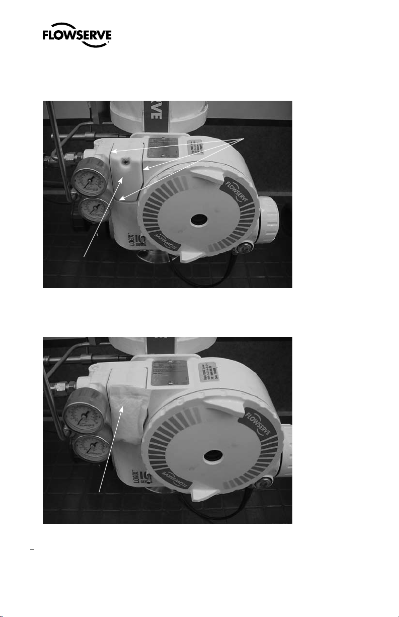
Logix 3400IQ Digital Positioner FCD LGENIM3401-00 – 06/06
The vent assembly is located in the upper left side of the positioner. The gaps around the assembly
as noted by the arrows should be sealed for long term storage.
Joints to be sealed
Vent assembly
A small desiccant package as shown can be included under the sealing tape to insure proper
protection.
Desiccant packet
6
Page 7
Logix 3400IQ Digital Positioner FCD LGENIM3401-00 – 06/06
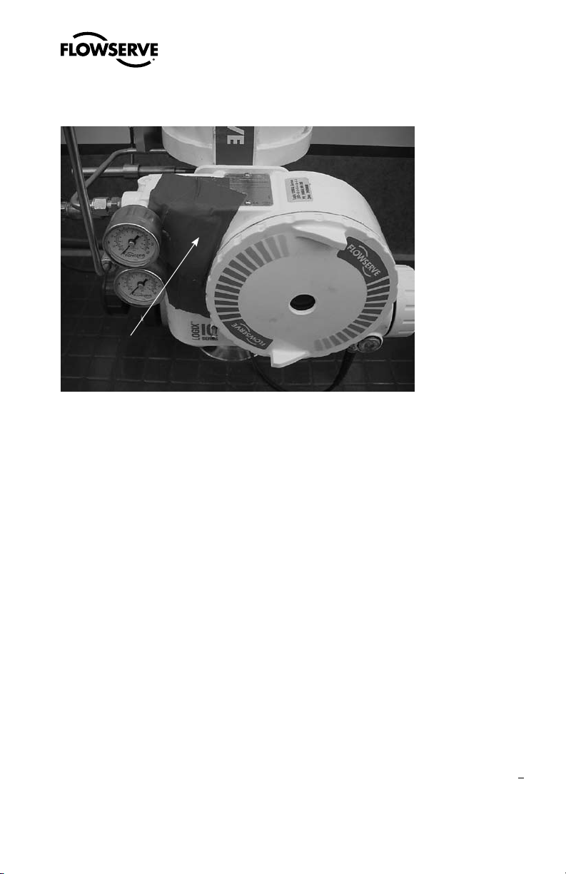
All of the edges around the vend assembly should be sealed similar to the picture below.
Removeable
sealing tape
The sealing tape and desiccant should be removed when instrument air is permanently applied to the
positioner.
3.3 Pre-installation Inspection
If a valve control package has been stored for more than one year, inspect one actuator by disassembling it per the appropriate Installation, Operation, and Maintenance Instructions (IOM) prior to
valve installation. If O-rings are out-of-round, deteriorated, or both, they must be replaced and the
actuator rebuilt. All actuators must then be disassembled and inspected. If the actuator O-rings are
replaced, complete the following steps:
1. Replace the pressure-balance plug O-rings.
2. Inspect the solenoid and positioner soft goods and replace as necessary.
4 Logix 3400IQ Positioner Overview
The Logix 3400IQ digital positioner is a two-wire Foundation Fieldbus compliant digital valve
positioner. The positioner is configurable through the local user interface. The Logix 3400IQ
the FF protocol to allow two-way remote communications with the positioner. The Logix 3400IQ
positioner can control both double- and single-acting actuators with linear or rotary mountings. The
positioner is completely powered by the FF signal. Start up voltage must be from a FF power supply
source.
utilizes
flowserve.com
7
Page 8
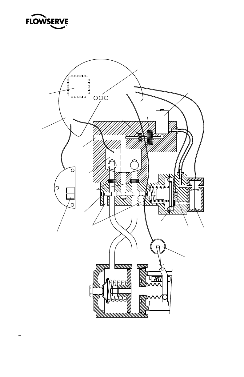
OO
Stem
Position
Sensor
Piezo Valve
Output 2
Output 1
Hall Effect
Sensor
Flame
Arrestor
Exhaust
Spool Valve
Flame
Arrestor
Pressure
Sensor Board
Air Supply
Main PCB
Regulator
Filter
Flame
Arrestor
Digital Position Algorithm
LED
Display
FF Input Signal
Logix 3400IQ Digital Positioner FCD LGENIM3401-00 – 06/06
Figure 1: Logix 3400IQ Digital Positioner Schematic (air-to-open configuration)
8
Page 9
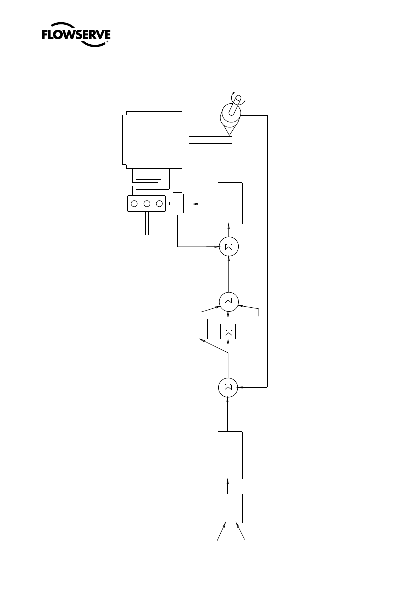
Figure 2: System Positioning Algorithm
Sensor
-
+
+
+
+
Summer
Integration
I
Offset
Loop
Inner
+
-
Gmult
Pmin
Pmax
Deviation
FOUNDATION
Fieldbus
Signal
Command In
(AO Block)
FOUNDATION
Fieldbus
Transducer
Block
CONTROL
COMMAND
Output
D/A
Percentage
Algorithm
Control
Supply
Air
Control
Spool
Loop
Inner
ATO
Tubed
Sensor
Position
Stem
Voltage
Valve
Piezo
MPC
Soft Limits
Characterization
Linear Mode
Output
Inner-Loop
Logix 3400IQ Digital Positioner FCD LGENIM3401-00 – 06/06
9
flowserve.com
Page 10
Logix 3400IQ Digital Positioner FCD LGENIM3401-00 – 06/06
4.1 Specifications
Table I: Electrical Specifications
Power Supply
IS Fisco compliant
Communications FF Protocol ITK 4.6x
Operating Current 23 mA
Maximum Voltage 36.0 VDC
Table II: Environmental Conditions
Operating Temperature Range Standard
Transport and Storage
Temperature Range
Operating Humidity 0 - 100% non-condensing
Note: The air supply must conform to ISA Standard ISA 7.0.01 (a dew point at least 18
degrees Fahrenheit below ambient temperature, particle size below five microns—one
micron recommended—and oil content not to exceed one part per million).
Two-wire, 9-32 VDC
FF compatible
-40° to 176°F
(-40° to 80°C)
-40° to 176°F (-40° to 80°C)
Table III: Physical Specifications
Housing Material Cast, powder-painted aluminum, stainless steel
Soft Goods Buna-N / Florosilicone
Weight
8.3 pounds (3.9 kg) aluminum
20.5 pounds (9.3 kg) stainless steel
Table IV: Positioner Specifications
Deadband <0.1% full scale
Repeatability <0.05% full scale
Linearity <0.5% (rotary), <0.8%, (sliding stem) full scale
3
Air Consumption <0.3 SCFM (0.5 Nm
Air Supply 30-150 psig (ISA 7.0.0.1 compliant)
/hr) @ 60 psi (4 bar)
10
Page 11
Logix 3400IQ Digital Positioner FCD LGENIM3401-00 – 06/06
Table V: Hazardous Area Certifications
Intrinsically Safe
(PENDING)
Explosion Proof
Approved
Class I, Div 1, Groups A, B, C, D
Class II, III, Div 1, Groups E, F, G
(See Figure 1 for installation
requirements.)
Intrinsically Safe
(PENDING)
Flameproof
(PENDING)
CE Compliant
FISCO Compliant
II 1G EEx ia IIC T4, T5
T4 Ta = -40°C to 80°C
T5 Ta = -40°C to 35°C
IP 65
II 2 GD EEx d IIB + H2
T5, Ta = -40°C to 80°C
IP65
Class I, Div 1, Groups B, C, D
Class II, III, Div 1, Groups E, F, G
T6 Ta = 60°C
NEMA/TYPE 4X
4.2 Positioner Operation
The Logix 3400IQ positioner is an electric feedback instrument. Figure 1 shows a Logix 3400IQ
positioner installed on a double-acting linear actuator for air-to-open action.
The Logix 3400IQ receives power from the two-wire, FF input signal. This positioner utilizes
FF communications for the command signal. The command source can be accessed with the
Rosemount 375 communicator or other host software.
0% is always defined as the valve closed position and 100% is always defined as the valve open
position. During stroke calibration, the signals corresponding to 0% and 100% are defined.
The input signal in percent passes through a characterization/limits modifier block. The positioner
no longer uses CAMs or other mechanical means to characterize the output of the positioner. This
function is done in software, which allows for in-the-field customer adjustment. The positioner has
four basic modes:
Linear, Equal Percent (=%), Quick Open (QO) and Custom characterization. In
Linear mode, the input signal is passed straight through to the control algorithm in a 1:1 transfer. In
Equal Percent (=%) mode, the input signal is mapped to a standard 30:1 rangeability =% curve. In
Quick Open the input signal is mapped to an industry standard quick-open curve. If Custom char-
acterization is enabled, the input signal is mapped to either a default =% output curve or a custom,
user-defined 21-point output curve. The custom user-defined 21-point output curve is defined using
a handheld or the Host configuration tool software. In addition, two user-defined features,
Soft
Limits and Final Value Cutoff, may affect the final input signal. The actual command being used to
flowserve.com
11
Page 12

Logix 3400IQ Digital Positioner FCD LGENIM3401-00 – 06/06
position the stem, after any characterization or user limits have been evaluated, is called the Control
Command.
The Logix 3400IQ
inner-loop, spool control and an outer-loop, stem position control. Referring again to Figure 1, a
stem position sensor provides a measurement of the stem movement. The
compared against the
the inner-loop control to move the spool up or down, depending upon the deviation. The inner-loop
then quickly adjusts the spool position. The actuator pressures change and the stem begins to
move. The stem movement reduces the deviation between
This process continues until the deviation goes to zero.
The inner-loop controls the position of the spool valve by means of a driver module. The driver
module consists of a temperature-compensated hall effect sensor and a piezo valve pressure
modulator. The piezo valve pressure modulator controls the air pressure under a diaphragm by
means of a piezo beam bender. The piezo beam deflects in response to an applied voltage from the
inner-loop electronics. As the voltage to the piezo valve increases, the piezo beam bends, closing off
against a nozzle causing the pressure under the diaphragm to increase. As the pressure under the
diaphragm increases or decreases, the spool valve moves up or down respectively. The hall effect
sensor transmits the position of the spool back to the inner-loop electronics for control purposes.
uses a two-stage, stem-positioning algorithm. The two stages consist of an
Control Command is
Stem Position. If any deviation exists, the control algorithm sends a signal to
Control Command and Stem Position.
4.3 Detailed Sequence of Positioner Operations
A more detailed example explains the control function. Assume the unit is configured as follows:
• Unit is in
• Custom characterization is disabled (therefore characterization is Linear).
• No soft limits enabled. No Final Value Cutoff set.
• Valve has zero deviation with a present input command of 50.
• Write to Final_Value to change command.
• Actuator is tubed and positioner is configured air-to-open.
Given these conditions, 50 represents a
is disabled so the
exists, the Stem Position is also at 50 percent. With the stem at the desired position, the spool valve
will be at a middle position that balances the pressures above and below the piston in the actuator.
This is commonly called the
OOS.
Command source of 50 percent. Custom characterization
Command source is passed 1:1 to the Control Command. Since zero deviation
null or balanced spool position.
Assume the input signal changes from 50 to 75. The positioner sees this as a
of 75 percent. With
is the difference between
where 50 percent is the present stem position. With this positive deviation, the control algorithm
12
sends a signal to move the spool up from its present position. As the spool moves up, the supply air
is applied to the bottom of the actuator and air is exhausted from the top of the actuator. This new
pressure differential causes the stem to start moving towards the desired position of 75 percent. As
Linear characterization, the Control Command becomes 75 percent. Deviation
Control Command and Stem Position: Deviation = 75% - 50% = +25%,
Command source
Page 13
Logix 3400IQ Digital Positioner FCD LGENIM3401-00 – 06/06
Logix 3400IQ
Positioner
Positioner
Bolts
Nut
Lock Washer
Nut
Follower Pin
Take-off Arm
Bolts
Stem Clamp
Bracket
Bolts
Bracket
Locknut
Washer
Follower
Arm
Nut
Metal Washers
the stem moves, the Deviation begins to decrease. The control algorithm begins to reduce the spool
opening. This process continues until the
Deviation goes to zero. At this point, the spool will be
back in its null or balanced position. Stem movement will stop and the desired stem position is now
achieved.
One important parameter has not been discussed to this point: Inner loop offset. Referring to Figure
2, a number called Inner loop offset is added to the output of the control algorithm. In order for the
spool to remain in its null or balanced position, the control algorithm must output a non-zero spool
command. This is the purpose of the
Inner loop offset. The value of this number is equivalent to the
signal that must be sent to the spool position control to bring it to a null position with zero deviation.
This parameter is important for proper control and is optimized and set automatically during stroke
calibration.
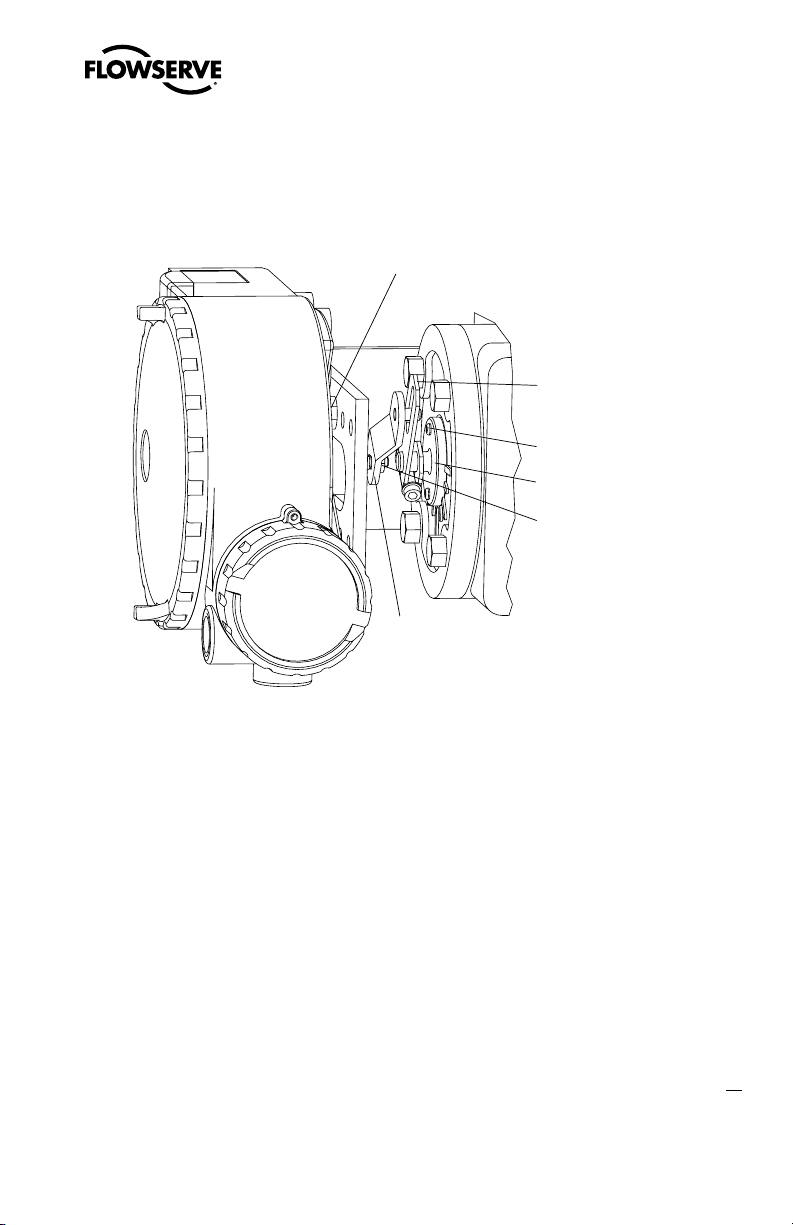
Figure 3: Linear Mark One Control Valve Mounting
13
flowserve.com
Page 14

Logix 3400IQ Digital Positioner FCD LGENIM3401-00 – 06/06
5 Mounting and Installation
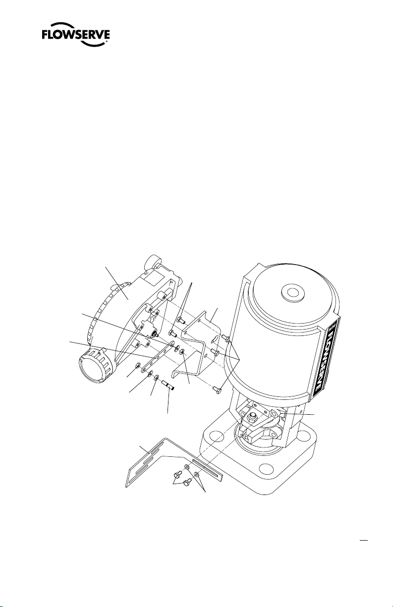
5.1 Mounting to Valtek Linear Mark One Valves
To mount a Logix 3400IQ positioner to a Valtek linear Mark One valve, refer to Figure 3 and proceed
as outlined below. The following tools are required:
• 9⁄16" open-end wrench (or ½" for spud sizes 2.88 and smaller)
• 7⁄16" box wrench
• 3⁄8" open-end wrench
1. Remove washer and nut from follower pin assembly. Insert pin into the appropriate hole in
follower arm, based on stroke length. The stroke lengths are stamped next to their corre
sponding holes in the follower arms. Make sure the unthreaded end of the pin is on the stamped
side of the arm. Reinstall lock washer and tighten nut to complete follower arm assembly.
2. Slide the double-D slot in the follower arm assembly over the flats on the position feedback shaft
in the back of the positioner. Make sure the arm is pointing toward the customer interface side
of the positioner. Slide lock washer over the threads on the shaft and tighten down the nut.
3. Align the bracket with the three outer mounting holes on the positioner. Fasten with ¼" bolts.
-
4. Screw one mounting bolt into the hole on the yoke mounting pad nearest the cylinder. Stop
when the bolt is approximately
5. Slip the large end of the teardrop shaped mounting hole in the back of the positioner/bracket
assembly over the mounting bolt. Slide the small end of the teardrop under the mounting bolt
and align the lower mounting hole.
6. Insert the lower mounting bolt and tighten the bolting.
7. Position the take-off arm mounting slot against the stem clamp mounting pad. Apply Loctite 222
to the take-off arm bolting and insert through washers into stem clamp. Leave bolts loose.
8. Slide the appropriate pin slot of the take-off arm, based on stroke length, over the follower arm
pin. The appropriate stroke lengths are stamped by each pin slot.
9. Center the take-off arm on the rolling sleeve of the follower pin.
10. Align the take-off arm with the top plane of the stem clamp and tighten bolting. Torque to 120
in-lb.
NOTE: If mounted properly, the follower arm should be horizontal when the valve is at 50%
stroke and should move approximately ±30° from horizontal over the full stroke of the valve.
14
If mounted incorrectly, a stroke calibration error will occur and the indicator lights will blink a
YRYR or YRRY code indicating the position sensor has gone out of range on one end of travel.
Reposition the feedback linkage or rotate the position sensor to correct the error.
3
⁄16" from being flush with mounting pad.
Page 15
Logix 3400IQ Digital Positioner FCD LGENIM3401-00 – 06/06
Positioner Bolts ¼-20 (4)*
* Located in ap propriate
hole pattern as indicated on
bracket. (25, 5 0, 100/200)
Take-off Arm, Rotary
Lock Washer (2)
10-32 Bolt
10-32 Nut
Self-tapping Screws (2)
Spline Lever Adapter
10-32 Nut
Lock Washer
Follower Arm
Logix 3400IQ
Digital Positioner
Bracket Bolts
-18 (2, not shown)
5
/
16
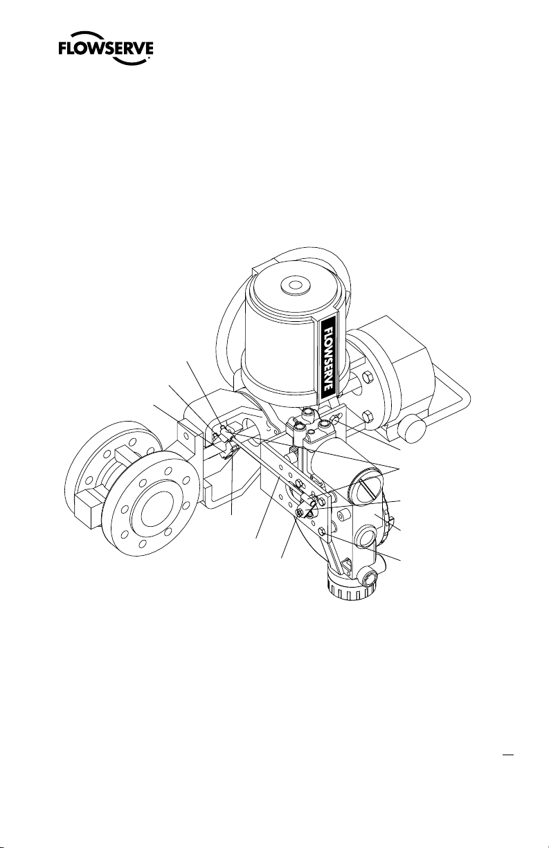
5.2 Mounting to Standard Valtek Rotary Valves (See Figure 4)
Figure 4: Standard Rotary Mounting
The standard rotary mounting applies to Valtek valve/actuator assemblies that do not have mounted
volume tanks or handwheels. The standard mounting uses a linkage directly coupled to the valve
shaft. This linkage has been designed to allow for minimal misalignment between the positioner and
the actuator. The tools required for the following procedure are:
• 5⁄32" Allen wrench
• ½" open-end wrench
• 7⁄16" open-end wrench
• 3⁄8" socket with extension
• 3⁄16" nutdriver
1. Fasten the spline lever adapter to the splined lever using two 6 x ½" self-tapping screws.
2. Slide the take-off arm assembly onto the spline lever adapter shaft. Insert the screw with star
washer through the take-off arm and add the second star washer and nut. Tighten nut with
socket so arm is lightly snug on the shaft but still able to rotate. This will be tightened after
linkage is correctly oriented.
3. Attach follower arm to positioner feedback shaft using the star washer and 10-32 nut.
flowserve.com
15
Page 16

Logix 3400IQ Digital Positioner FCD LGENIM3401-00 – 06/06
NOTE: The arm will point up when feedback shaft is in the free position.
4. Using four ¼-20 x ½" bolts, fasten positioner to universal bracket using appropriate hole pattern
(stamped on bracket).
5
5. Using a ½" end wrench and two
⁄16-18 x ½" bolts, attach bracket to actuator transfer case pad.
Leave these bolts slightly loose until final adjustments are made.
6. Rotate take-off arm so the follower pin will slide into the slot on the take-off arm. Adjust the
bracket position as needed noting the engagement of the follower pin and the take-off arm
slot. The pin should extend approximately
1
⁄16" past the take-off arm. When properly adjusted,
securely tighten the bracketing bolts.
Orienting the Take-off Arm for Final Lock Down
1. Tube the Logix 3400IQ
positioner to the actuator according to the instructions given in Section
5.5, “Tubing Positioner to Actuator.”
2. With supply pressure off, rotate the follower arm in the same direction the shaft would rotate
upon a loss of supply pressure. When the mechanical stop of the follower arm (positioner) is
reached, rotate back approximately 15 degrees.
3. Hold the take-off arm in place; tighten the screw of the take-off arm.
NOTE: The take-off arm should be snug enough to hold the follower arm in place but allow
movement when pushed.
4. Connect regulated air supply to appropriate port in manifold.
5. Remove main cover and locate DIP switches and RE-CAL button.
6. Refer to sticker on main board cover and set DIP switches accordingly. (A more detailed
explanation of the DIP switch settings is given in Section 7, “Startup.”)
7. Press the RE-CAL button for three to four seconds or until the positioner begins to move. The
positioner will now perform a stroke calibration.
8. If the calibration was successful the green LED will blink GGGG or GGGY and the valve will be in
control mode. Continue with step 9. If calibration failed, as indicated by a YRYR or YRRY blink
code, the A/D feedback values were exceeded and the arm must be adjusted away from the
positioners limits. Return to step 2 and rotate the arm back approximately 10 degrees.
NOTE: Remember to remove the air supply before re-adjusting take-off arm.
9. Tighten the nut on the take-off arm. The socket head screw of the take-off arm must be tight,
about 40 in-lb.
16
NOTE: If the take-off arm slips, the positioner must be recalibrated.
Page 17
Logix 3400IQ Digital Positioner FCD LGENIM3401-00 – 06/06
5SJQQFS
5SJQQFS$MBNQ
#PMUT
-PDLOVUT
5JF3PE
/VU
-PDL8BTIFS
#SBDLFU#PMUT
#BMM+PJOU&OET
'PMMPXFS"SN
3PUBUF1PTJUJPOFS¡
.PVOUJOH#PMUT
5JF3PENVTU CFDVUUPEFTJS FEMFOHUI
7BMUFL
WARNING: Failure to follow this procedure will result in positioner and/or linkage
c
damage. Check air-action and stroke carefully before lockdown of take-off arm to
spline lever adapter.
5.3 Optional Valtek Rotary Mounting Procedure (See Figure 5)
Figure 5: Optional Rotary Mounting
The optional rotary mounting applies to Valtek valve/actuator assemblies that are equipped with
mounted volume tanks or handwheels. The optional mounting uses a four-bar linkage coupled to the
valve shaft. The following tools are required:
• 3⁄8" open-end wrench
• 7⁄16" open-end wrench
• ½" open-end wrench
1. Using a ½" open-end wrench and two 5⁄16-18 x ½" bolts, attach bracket to actuator transfer case
pads. Leave bracket loose to allow for adjustment.
17
flowserve.com
Page 18

Logix 3400IQ Digital Positioner FCD LGENIM3401-00 – 06/06
2. Using four ¼-20 x ½" bolts and a 7⁄16" open-end wrench, fasten positioner to universal bracket,
using the four-hole pattern that locates the positioner the farthest from the valve. Rotate
positioner 90 degrees from normal so gauges are facing upward.
3. Attach follower arm to positioner feedback shaft, using the star washer and 10-32 nut.
4. Attach tripper and tripper clamp to valve shaft using two ¼-20 bolts and two ¼-20 locknuts.
Leave tripper loose on shaft until final adjustment.
5. Thread ball joint linkage end to tripper and tighten (thread locking compound such as Loctite
is recommended to prevent back threading). Adjust the length of tie rod so follower arm and
tripper rotate parallel to each other (the rod must be cut to the desired length). Connect the
other ball joint end to follower arm using a star washer and a 10-32 nut.
6. Tighten bracket and tripper bolting.
7. Check for proper operation, note direction of rotation.
WARNING: If rotating in wrong direction, serious damage will occur to the positioner
c
and/or linkage. Check air action and stroke direction carefully before initiating
operation.
5.4 NAMUR Mounting Option
Logix 3200IQ is available with a NAMUR output shaft and mounts on an actuator using the ISO F05
holes. Proper alignment of the positioner shaft to the actuator shaft is very important since improper
alignment can cause excess wear and friction to the positioner.
5.5 Tubing Positioner to Actuator
The Logix 3400IQ digital positioner is insensitive to supply pressure changes and can handle supply
pressures from 30 to 150 psig. A supply regulator is recommended if the customer will be using
the diagnostic features of the Logix 3400IQ
pressure is higher than the maximum actuator pressure rating a supply regulator is required to lower
the pressure to the actuator’s maximum rating (not to be confused with operating range). An air filter
is highly recommended for all applications where dirty air is a possibility.
NOTE: The air supply must conform to ISA Standard ISA 7.0.01 (a dew point at least 18°F below
ambient temperature, particle size below five microns—one micron recommended—and oil content
not to exceed one part per million).
Air-to-open and air-to-close are determined by the actuator tubing, not the software. When air action
selection is made during configuration, that selection tells the control which way the actuator has
18
been tubed. The top output port is called
must receive air to begin the correct action on increasing signal. Verify that tubing is correct prior to
a stroke calibration. Proper tubing orientation is critical for the positioner to function correctly and
have the proper failure mode. Refer to Figure 1 and follow the instructions below:
but is not required. In applications where the supply
Output 1. It should be tubed to the side of the actuator that
Page 19

Logix 3400IQ Digital Positioner FCD LGENIM3401-00 – 06/06
Linear Double-acting Actuators
For a linear air-to-open actuator, the Output 1 port of the positioner manifold is tubed to the bottom
side of the actuator. The Output 2 port of the positioner manifold is tubed to the top side of the
actuator. For a linear air-to-close actuator the above configuration is reversed.
Rotary Double-acting Actuators
For a rotary actuator, the Output 1 port of the positioner manifold is tubed to the bottom side of the
actuator. The Output 2 port of the positioner manifold is tubed to the top side of the actuator. This
tubing convention is followed regardless of air action. On rotary actuators, the transfer case orienta
tion determines the air action.
Single-acting Actuators
For single-acting actuators, the Output 1 port is always tubed to the pneumatic side of the actuator
regardless of air action. The Output 2 port must be plugged.
6 Wiring and Grounding Guidelines (See Figure 6)
WARNING: This product has electrical conduit connections in either thread sizes ½" NPT
c
or M20 which appear identical but are not interchangeable. Housings with M20 threads
are stamped with the letters M20 above the conduit opening. Forcing dissimilar threads
together will damage equipment, cause personal injury and void hazardous location
certifications. Conduit fittings must match equipment housing threads before installation. If
threads do not match, obtain suitable adapters or contact a Flowserve representative.
-
6.1 FF Command Input Wiring
The Logix 3400IQ is non-polarity sensitive. Wire FF source to the input terminals (see Figure 6).
Minimum operating voltage is 9 VDC.
The FF signal to the Logix 3400IQ digital positioner should be in shielded cable. Shields must be
tied to a ground at only one end of the cable to provide a place for environmental electrical noise
to be removed from the cable. In general, shield wire should be connected at the source. Refer to
guidelines in FF AG-181 for proper wiring methods.
NOTE: The Logix 3400IQ positioner carries an intrinsically safe barrier rating of 250 mA. Input
currents should not exceed 250 mA, 5 watts.
6.2 Grounding Screw
The green grounding screw, located inside the termination cap, should be used to provide the unit
with an adequate and reliable earth ground reference. This ground should be tied to the same ground
as the electrical conduit. Additionally, the electrical conduit should be earth grounded at both ends of
its run.
flowserve.com
19
Page 20
Figure 6: Field Termination
Shielded Cable
FF Signal
Connect Shield at Source
Housing EARTH
Terminal
External
Bonding
Location
FF Field
Terminators
Environmental
Seal
Logix 3400IQ Digital Positioner FCD LGENIM3401-00 – 06/06
20
WARNING: The green grounding screw must not be used to terminate signal shield wires.
c
6.3 Segment Compliance Voltage (See Figure 7)
Output compliance voltage refers to the voltage limit that can be provided by the FF source. A FF
system consists of the FF source, wiring resistance, barrier resistance (if present), and the Logix
3400IQ positioner voltage. The Logix 3400IQ digital positioner requires that the system allows for a
9.0 VDC drop across the positioner at minimum segment voltage. The actual voltage at the terminals
varies from 9.0 to 32.0 VDC depending on the FF signal and ambient temperature.
Determine if the segment will support the Logix 3400IQ
digital positioner by performing the following
calculation.
Voltage = Compliance Voltage (@ 23 mA) –
23 mA • (R
barrier
+ R
)
wire
Equation 1
Page 21
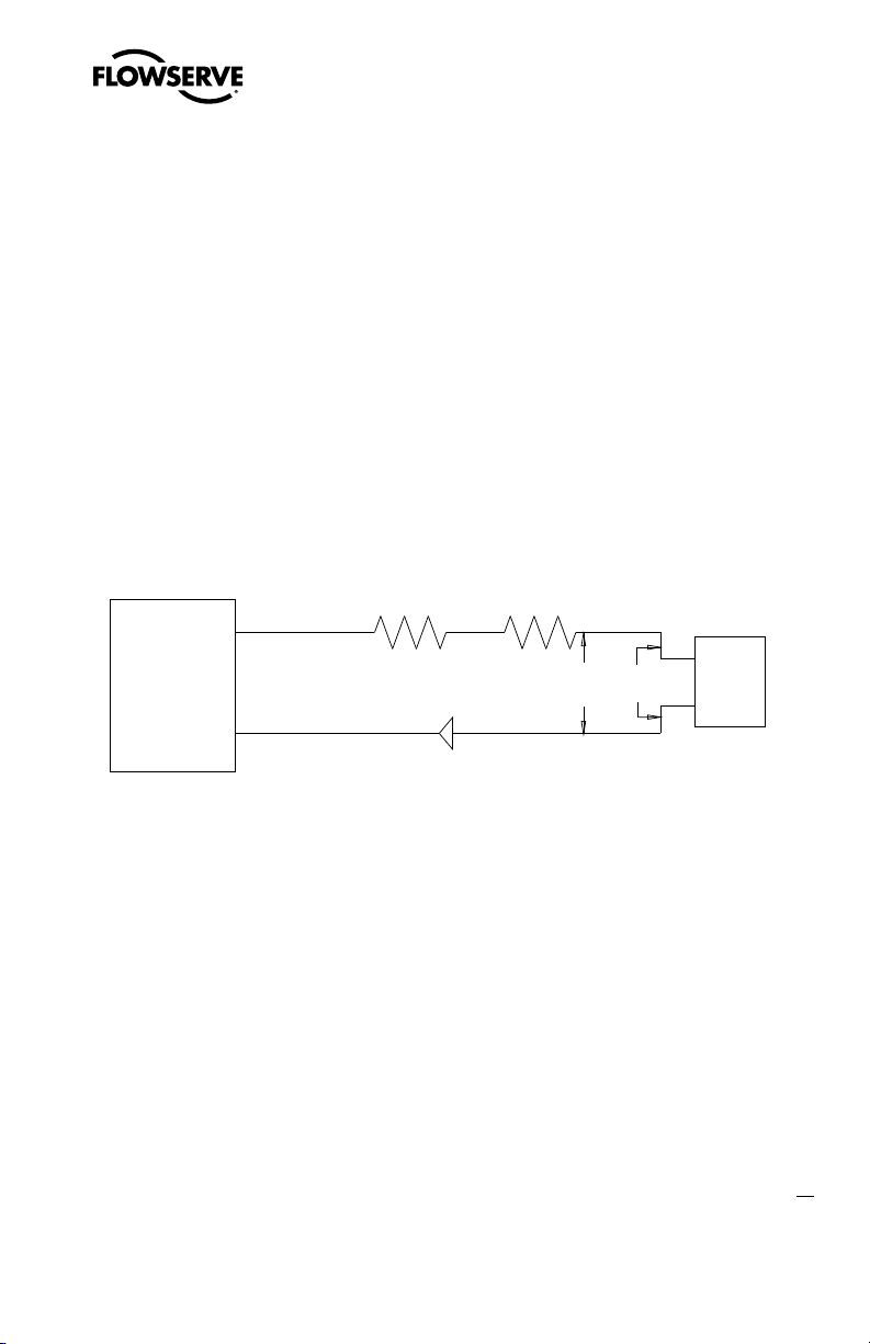
Logix 3400IQ Digital Positioner FCD LGENIM3401-00 – 06/06
+
-
R
barrier
(if present)
R
wire
FF
Signal
Source
Compliance
Voltage
Logix
3400IQ
Current
23 mA
9 VDC min
The calculated voltage must be greater than 9 VDC in order to safely support the Logix 3400IQ digital
positioner.
Example:
DCS Compliance Voltage = 19 VDC
R
= 300 Ω
barrier
R
= 25 Ω
wire
Current
= 23 mA
max
Voltage = 19 VDC – 0.023 A • (300 Ω + 25 Ω) = 11.5 VDC
The voltage 11.5 VDC is greater than the required 9.0 VDC; therefore, this system will support the
Logix 3400IQ
digital positioner.
Figure 7: Compliance Voltage
6.4 Cable Requirements
The Logix 3400IQ digital positioner utilizes the FF protocol. This communication signal is superimposed on the supply voltage.
FF rated cable should be used. Refer to H1 wiring specification.
6.5 Intrinsically Safe Barriers
When selecting an intrinsically safe barrier, make sure the barrier is FF compatible. Although the
barrier will pass the segment voltage and allow normal positioner operation, if not compatible, it may
prevent FF communication.
6.6 DD Support
The DD for the Logix 3400IQ can be downloaded from either the flowserve website: www.flowserve.
com or the F
oundation Fieldbus website: www.Fieldbus.org.
21
flowserve.com
Page 22
Logix 3400IQ Digital Positioner FCD LGENIM3401-00 – 06/06
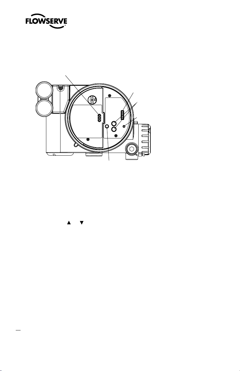
LEDs
DIP Switch Block
Jog Buttons
Rotary
Selector
Switch
RE-CAL Button
7 Startup
Figure 8: Local User Interface
7.1 Logix 3400IQ Local Interface Operation
The Logix 3400IQ local user interface (Figure 8) allows the user to configure the basic operation of
the positioner, tune the response, and calibrate the positioner without additional tools or configura
tors. The local interface consists of a RE-CAL button for automatic zero and span setting, along
with two jog buttons (
position. There is also a DIP switch block containing eight switches. Six of the switches are for basic
configuration settings and two are for FF options. There is also a rotary selector switch for adjusting
the positioner gain settings. For indication of the operational status or alarm conditions there are
three LEDs on the local user interface.
and ) for spanning valve/actuators with no fixed internal stop in the open
-
7.2 Initial DIP Switch Settings
Before placing the unit in service, set the DIP switches in the Configuration boxes to the desired
control options. A detailed description of each DIP switch setting follows.
NOTE: The Logix 3400IQ positioner reads the DIP switch settings each time the RE-CAL button is
pressed. If a FF handheld or Host software is used to configure and then calibrate the positioner, the
DIP switches are not read. The auto-tune adjustment switch labeled “GAIN” is always live and can be
adjusted at any time.
22
Transducer block settings will always override the DIP switch settings until the RE-CAL button is
pressed.
Page 23

Logix 3400IQ Digital Positioner FCD LGENIM3401-00 – 06/06
7.3 Description of Configuration DIP Switch Settings
The first six DIP switches are for basic configuration. The function of each switch is described below.
Air Action
This must be set to match the configuration of the valve/actuator mechanical tubing connection and
spring location since these determine the air action of the system.
ATO (air-to-open)
Selecting ATO if increasing output pressure from the positioner is tubed so it will cause the valve to
open.
ATC (air-to-close)
Selecting ATC if increasing output pressure from the positioner is tubed so it will cause the valve to
close.
Pos. Characterization
Linear Select
Linear if the actuator position should be directly proportional to the input signal.
Other Select
Flags parameter in the transducer block.
Optional Pos. Characterization
If the Pos. Characterization switch is set to Other then this parameter is active with the following
options:
=% The =% option will characterize the actuator response to the input signal based on a standard 30:1
equal percent rangeability curve.
QO Quick open is based on a standard industry quick-open curve.
Custom If
set-up using a properly configured 375 handheld or other host software.
can be thought of as a “soft CAM.” The user can define a characterization curve using 21 points. The
control will linearly interpolate between points. Points do not have to be equally spaced in order to
allow more definition at critical curve areas. The default values will linearize the output of a valve with
an inherent =% characteristic (e.g. ball valves.)
Other if another characteristic is desired, which is set in conjunction with the Control_
Custom is selected, the positioner will be characterized to a custom table that must be
Custom characterization
23
flowserve.com
Page 24
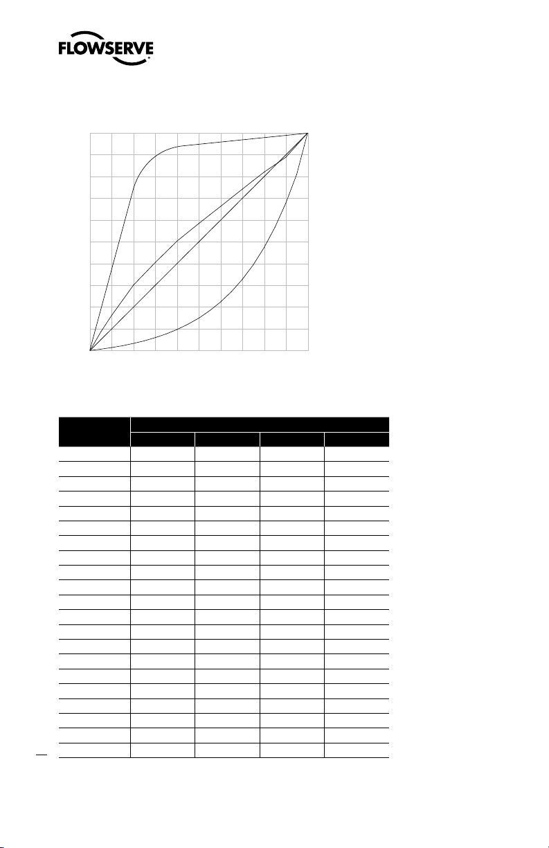
Figure 9: Default Custom Characterization
% Command
% Control Command
0 10 20 30 40 50 60 70 80 90 100
0
10
20
30
40
50
60
70
80
90
100
=%
Linear
Custom
Quick Open
Table VI : Characteristic Curve Data
% Command
0 0 0 0 0
5 0.62 5 8.66 18.8
10 1.35 10 16.24 37.6
15 2.22 15 23.17 56.4
20 3.25 20 30.11 74.0
25 4.47 25 35.31 84.3
30 5.91 30 40.51 90.0
35 7.63 35 45.42 92.0
40 9.66 40 50.34 93.4
45 12.07 45 54.40 94.2
24
50 14.92 50 58.47 94.8
55 18.31 55 62.39 95.5
60 22.32 60 66.31 96.0
65 27.08 65 70.27 96.5
70 32.71 70 74.23 97.0
75 39.40 75 78.17 97.5
80 47.32 80 82.11 98.0
85 56.71 85 85.50 98.5
90 67.84 90 88.89 99.0
95 81.03 95 94.45 99.5
100 100.00 100 100.00 100.0
=% Linear Custom QO
Logix 3400IQ Digital Positioner FCD LGENIM3401-00 – 06/06
% Control Command
Page 25

Logix 3400IQ Digital Positioner FCD LGENIM3401-00 – 06/06
A
GAIN
B
C
D
E
F
G
H
Auto Tune
This switch controls whether the positioner will auto tune itself every time the RE-CAL button is
pressed or use preset tuning parameters.
On
On enables an auto tune feature that will automatically determine the positioner gain settings
based on the current position of the adjustable GAIN switch setting and response parameters
measured during the last RE-CAL. The GAIN switch is live, meaning the settings can be adjusted at
any time by changing the rotary switch position. (Note that there is a small black arrow indicating the
selection. The slot in the switch is NOT the indicator.)
Figure 10: Adjustable GAIN Switch
If the adjustable GAIN selector switch is set to “E” with the auto tune switch on, a Flowserve standard
response tuning set will be calculated and used based on response parameters measured during the
last RE-CAL.
If the adjustable GAIN selector switch is set to “D”, “C”, “B”, or “A” with the auto tune switch on,
progressively lower gain settings will be used based on response parameters measured during the
last RE-CAL.
If the adjustable GAIN selector switch is set to “F”, “G”, or “H” with the auto tune switch on, progres
sively higher gain settings will be calculated and used based on response parameters measured
during the last RE-CAL.
Off Off forces the positioner to use one of the factory preset tuning sets determined by the
adjustable GAIN selector switch. Settings “A” through “H” are progressively higher gain predefined
tuning sets. The GAIN selector switch is live and can be adjusted at any time to modify the tuning
parameters.
NOTE: “E” is the default adjustable GAIN selector switch setting for all actuator sizes. Raising or
lowering the gain setting is a function of the positioner/valve response to the control signal, and
is not actuator size dependent.
Stability Switch
This switch adjusts the position control algorithm of the positioner for use with low-friction control
valves or high-friction automated valves.
Low-Friction Valves Placing the switch to the left optimizes the response for low-friction, highperformance control valves. This setting provides for optimum response times when used with most
low-friction control valves.
flowserve.com
25
Page 26

Logix 3400IQ Digital Positioner FCD LGENIM3401-00 – 06/06
High-Friction Valves Placing the switch to the right optimizes the response for valves and actuators with high friction levels. This setting slightly slows the response and will normally stop limit
cycling that can occur on high-friction valves.
7.4 Description of Cal DIP Switch Settings
The sixth DIP switch selects between two calibration options. The function of the Cal DIP switch is
described below.
NOTE: The unit must be in OOS mode before a calibration sequence can begin.
Auto Select
mode the positioner will fully
the stop to register the 100% position when performing a self-calibration. See detailed instructions in
the next section on how to perform an auto positioner calibration.
Jog Select
In the
to set the open position using the Jog buttons labeled with the up and down arrows. See the detailed
instructions in Section 7.6 on how to perform a manual calibration using the Jog buttons.
Auto if the valve/actuator assembly has an internal stop in the open position. In Auto
close the valve and register the 0% position and then open the valve to
Jog if the valve/actuator assembly has no physical calibration stop in the open position.
Jog mode the positioner will fully close the valve for the 0% position and then wait for the user
WARNING: During the RE-CAL operation the valve may stroke unexpectedly. Notify
c
proper personnel that the valve will stroke, and make sure the valve is properly
isolated.
7.5 RE-CAL Operation
NOTE: The unit must be in OOS mode before a calibration sequence can begin.
The RE-CAL button is used to locally initiate a calibration of the positioner. Pressing and holding the
RE-CAL button for approximately three seconds will initiate the calibration. If the Config-Switches
option is enabled, the settings of all the configuration switches are read and the operation of the
positioner adjusted accordingly. A RE-CAL can be aborted at any time by briefly pressing the RE-CAL
button and the previous settings will be retained.
If the Quick Calibration switch (be careful not to confuse this with the RE-CAL button) is set to
Auto and the valve/actuator assembly has the necessary internal stops the calibration will complete
automatically. While the calibration is in progress you will notice a series of different lights flashing
indicating the calibration progress. When the lights return to a sequence that starts with a green light
the calibration is complete. An explanation of the various light sequences follows. The initial calibra
tion of extremely large or small actuators may require several calibration attempts. The positioner
adapts to the actuator performance and begins each calibration where the last attempt ended. On an
initial installation it is recommended that after the first successful calibration that one more calibra
26
tion be completed for optimum performance.
-
-
Page 27

Logix 3400IQ Digital Positioner FCD LGENIM3401-00 – 06/06
WARNING: When operating using RE-CAL or local control, the valve will not respond to
c
external commands. Notify proper personnel that the valve will not respond to remote
command changes, and make sure the valve is properly isolated.
7.6 Manual Jog Calibration Operation
If the Quick Calibration switch is set to Jog, the calibration will initially close the valve then cause
a small jump in the valve position. The jog calibration process will only allow the user to manually
set the span; zero position is automatically always set at the seat. If an elevated zero is needed a
handheld or other PC-based configuration software is required. When performing a jog calibration,
the LEDs will flash in a sequence of Y-R-R-G (yellow-red-red-green) which indicates that the user
must use the Jog buttons (
stem is properly positioned press both the Jog buttons (
the 100% position and proceed. No more user actions are required while the calibration process
is completed. When the lights return to a sequence that starts with a green light the calibration is
complete. An explanation of the various light sequences follows.
and ) to manually position the valve to the 100% position. When the
and ) simultaneously again to register
7.7 Local Control of Valve Position
Local control of valve position can be achieved from the user interface by holding down both Jog
buttons and the RE-CAL button simultaneously for three seconds. While in this mode the LEDs will
flash a YGRR (yellow-green-red-red) sequence. Use the two Jog buttons (
control the position of the valve. To exit the local control mode and return to normal operation, briefly
press the RE-CAL button.
and ) to manually
7.8 Factory Reset
To perform a factory reset, disconnect power, hold the RE-CAL button down, and reconnect power.
Performing a factory reset will cause all of the internal variables, including calibration, to be reset
to factory defaults. The positioner must be recalibrated after a factory reset. User configured limits,
alarm settings, and valve information will also need to be restored.
WARNING: Performing a factory reset may result in the inability to operate the valve until
c
reconfigured properly. Notify proper personnel that the valve may stroke, and make sure the
valve is properly isolated.
7.9 Logix 3400IQ Status Condition
The blink codes used to convey the status of the Logix 3400IQ digital positioner are described in the
table below. In general, any sequence starting with a green light flashing first is a normal operating
mode and indicates that there are no internal problems. Any sequence starting with a yellow light
flashing indicates that the unit is in a special calibration or test mode, or that there was a calibra
-
flowserve.com
27
Page 28

Logix 3400IQ Digital Positioner FCD LGENIM3401-00 – 06/06
tion problem. Any sequence starting with a red light flashing indicates that there is an operational
problem with the unit.
Table VII: Status and Conditions
Indication and Resolution
Colors
Identifier
G - - - Any sequence starting with a green light flashing first is a normal operating mode and
GGGG 1 Normal operation No errors, alerts, or warnings.
GGGY 2 Final Value cutoff active The command is below or above the user-set limits for tight
GGYR 4 Initializing This sequence should only be visible for three sequences when powering up
GGRG 5 Cycle limit exceeded (user-set) The cycle limit set by the user has been exceeded. To clear
GGRY 6 Travel limit exceeded (user-set) The total accumulated travel limit set by the user has been
GYYR 7 Soft Stop Low (user-set) The unit is being commanded to exceed a user-defined lower
GYRY 8 Soft Stop High (user-set) The unit is being commanded to exceed a user-defined upper
GRYR 9 Posalert Low (user-set) The position has reached or is exceeding a user-defined lower
GRRY 10 Posalert High (user-set) The position has reached or is exceeding a user-defined upper
Y - - -
YGYG 11 Signature test in progress This is a test initiated by Host software that can only be
YRGG 13 Stroke calibration in progress Calibration sequence started either using the local RE-CAL
28
Continued on page 29
indicates that there are no internal problems.
shutoff feature. This is a normal condition for a closed valve. The factory default setting is 1%
and 110% command. To clear the condition use handheld or Host software to reset the tight
shutoff if the range is incorrect or adjust the command signal above the specified Final Value
cutoff.
the unit.
use handheld or Host software to reset.
exceeded. To clear use handheld or Host software to reset.
position limit and the internal software is holding the position at the limit. The function is
similar to a mechanical limit stop except it is not active if the unit is un-powered. To clear the
condition use handheld or Host software to reset the limit if more travel is needed or adjust
the command signal back in the specified range.
position indicator similar to a limit switch indicator. To clear the condition use handheld or
Host software to reset the indicator if more travel is needed or adjust the command signal
back in the specified range.
position indicator similar to a limit switch indicator. To clear the condition use handheld or
Host software to reset the indicator if more travel is needed or adjust the command signal
back in the specified range.
Any sequence starting with a yellow light indicates that the unit is in a special calibration
or test mode, or that there was a calibration problem.
cancelled by that software.
button or by a handheld or Host software. It may be cancelled by briefly pushing the RE-CAL
button.
Page 29

Logix 3400IQ Digital Positioner FCD LGENIM3401-00 – 06/06
Table VII: Status and Conditions (continued)
Indication and Resolution
Colors
Identifier
YGRR 14 Local jog control mode The unit has been placed in a local override mode where the valve
YYGR 15 Pressure calibration in progress Calibration sequence controlled by a handheld or Host
YYYY 16 Local user interface disabled Host software has been used to disable the local interface. If
YRRG 17 Waiting Adjust to full open position setting from User—only used during Jog calibration
YRYG 18 Setting IL offset while calibrating An automatic step in the calibration process that is done
YRYY 19 No feedback motion while calibrating Indicates that there was no motion of the actuator
YRYR 20 Feedback 0% out of range Calibration error indicating that the position sensor was out
YRRY 21 Feedback 100% out of range Calibration error indicating that the position sensor was
YRRR 22 Feedback span too small The range of motion of the position feedback arm was too small
YRGR 23 Feedback unstable while calibrating Check for loose linkages or loose positioner sensor.
R - - -
RGRR 24 Position deviation (user-set) The position has exceeded user-defined error band between
RGYY 25 Pressure reading out of range The internal pressure sensors are either saturated with a
Continued on page 30
can only be stroked using the two local jog buttons. It may be cancelled by briefly pushing the
RE-CAL button.
software that can only be cancelled by that software.
local control is desired then the local interface must be re-enabled from the remote software.
This code is only present for a short time when the RE-CAL button is pressed.
see explanation in Section 7.5, “RE-CAL,” for operation.
with the valve at 50% position. This must be completed for proper calibration.
based on the current stroke time configuration. Check linkages and air supply to make sure
the system is properly connected. If the time out occurred because the actuator is very large
then simply retry the RE-CAL and the positioner will automatically adjust for a larger actuator
by doubling the time allowed for movement. This error may be cleared by briefly pushing
the RE-CAL button, which will force the positioner to use the parameters from the last good
calibration.
of range during the calibration of the closed position. To correct the condition, adjust the
positioner mounting, linkage or feedback potentiometer to move the position sensor back into
range then restart the calibration. This error may be cleared by briefly pushing the RE-CAL
button, which will force the positioner to use the parameters from the last good calibration.
out of range during the calibration of the open position. To correct the condition, adjust the
positioner mounting, linkage or feedback potentiometer to move the position sensor back into
range then restart the calibration. This error may be cleared by briefly pushing the RE-CAL
button, which will force the positioner to use the parameters from the last good calibration.
for optimum performance. Check for loose linkages and/or adjust the feedback pin to a position closer to the follower arm pivot to create a larger angle of rotation and recalibrate. Briefly
pushing the RE-CAL button acknowledges this condition and the positioner will operate using
the current short stroke calibration if otherwise a good calibration.
This error may be cleared by briefly pushing the RE-CAL button, which will force the
positioner to use the parameters from the last good calibration. This error may appear on
some very small actuators during the initial calibration. Redoing the calibration may clear the
problem.
Any sequence starting with a red light indicates that there is an operational problem with
the unit.
command and position.
pressure over 150 psi or the sensor has failed. Check supply pressure and if OK check the
pressure sensor board connections and replace pressure sensor board if necessary.
29
flowserve.com
Page 30

Logix 3400IQ Digital Positioner FCD LGENIM3401-00 – 06/06
Table VII: Status and Conditions (continued)
Indication and Resolution
Colors
Identifier
RGYR 26 Loss of supply pressure The Positioner has determined that the supply pressure is below
RYGG Factory reset condition Recalibrate.
RYYY 27 Pilot relay non-motion alert Check to make sure the air supply is connected. Also check
15 psi. Check the supply pressure and if OK check the pressure sensor board connections
and replace pressure sensor board if necessary. Minimum recommended supply pressure is
30 psi for proper operation.
the internal wiring harnesses for good connections. This error may be cleared by briefly
pushing the RE-CAL button, which will force the positioner to use the parameters from the
last good calibration. If the positioner still does not operate replace the pneumatic relay
assembly.
RRGG 30 Watchdog timer timeout (also listed as internal voltage reference) This is often caused
RRYG 31 Internal temperature alert The internal positioner temperature is currently exceeding
RRYY 32 Piezo voltage error Bad electronic assembly, replace.
RRYR 33 Internal voltage reference error Indicates that the circuit board is drawing too much
RRRG Loss of Inter-PCB Communications Cycle power to restart.
RRRY 34 NV RAM checksum error The checksum of the internal data was not updated correctly.
when intermittent operation occurs when connecting power. Remove power and then reconnect to clear. If problem persists it is a bad electronic assembly, replace.
operational limits of -40ºF (-40ºC) or 185ºF (85ºC).
power. Check internal wiring and connectors for electrical shorts—if no shorts are present,
replace the electronic assembly.
Cycle power and complete a RE-CAL if error persists. Check internal data to verify correct
settings. If the error still occurs, replace the electronic assembly.
7.10 Version Number Checking
The version number of the embedded code may be checked at any time except during a calibration
by holding down the up arrow Jog button (
to change the blink sequence to three blinks indicating the major version number. Holding the down
arrow Jog button (
) will give the minor version number without affecting operation. The version
codes are interpreted by adding up the numbers assigned according to the following table:
Color First blink value Second blink value Third blink value
Green 0 0 0
Yellow 9 3 1
Red 18 6 2
30
). This will not alter the operation of the unit other than
Page 31

Logix 3400IQ Digital Positioner FCD LGENIM3401-00 – 06/06
For example if holding the up arrow Jog button ( ) gave a G-G-R code, and holding the down arrow
Jog button (
version 2.12.
) gave a Y-Y-G code then the resulting version number would be (0+0+2).(9+3+0) or
7.11 375 Handheld Communicator
The Logix 3400IQ Quick Start Guide is available from a Flowserve representative.
The Logix 3400IQ
The Device Description (DD) files and the manuals listed below can be obtained from the FF
Foundation or from your Flowserve representative. For more information please see the following
guides:
• Product Manual for the 375 Communicator.
• Logix 3400IQ
Diagnostic features such as the signature tests and ramp tests are performed internally. Certain
calibration features such as actuator pressure sensor calibrations are performed using the 375
Handheld Communicator or using the Host software.
digital positioner supports and is supported by the 375 Handheld Communicator.
Digital Positioner Reference Manual.
7.12 Device Description (DD) Files
The DD files for the Logix 3400 can be downloaded from the Flowserve website, http://fcd.flowserve.
com/valves/softwareDownload.jsp, or the Foundation Fieldbus website, www.fieldbus.org.
7.13 Calibration
7.13.1 CALIBRATE_FLAGS
Position 0% Calibration Flag in CALIBRATE_FLAGS
During stroke calibration, the Logix 3400 digital positioner checks to see if the linkage is placing the
stem position sensor in range. If the valve stroke causes stem position measurement to go out of
range in the closed position, a Position 0% Flag will be generated. The valve stem will stop in the
closed position and the red LED will blink. Linkage must be adjusted to bring the sensor in range.
Special LED indication: If the linkage is out of range, the LEDs can be used as an adjustment guide.
The LED will change from a red to yellow when the linkage is brought into range.
Position 100% Calibration Flag in CALIBRATE_FLAGS
During stroke calibration, the Logix 3400IQ digital positioner checks to see if the linkage is placing
the stem position sensor in range. If the valve stroke causes stem position measurement to go out
of range in the open position, a Position 100% Flag will be generated. The valve stem will stop in
the open position and the red LED will blink. Linkage must be adjusted to bring the sensor in range.
Special LED indication: If the linkage is out of range, the LEDs can be used as an adjustment guide.
The LED will change from a red to yellow when the linkage is brought into range.
flowserve.com
31
Page 32

Logix 3400IQ Digital Positioner FCD LGENIM3401-00 – 06/06
Position Span Flag in CALIBRATE_FLAGS
Position span is a check during stroke calibration to verify that the valve stem moved. The algorithm
waits to see if no movement is detected when the valve is automatically stroked open. Anything
that could prevent the valve from stroking will generate a Position Span error (no supply pressure,
malfunctioning spool valve).
7.13.2 Control and Tuning
Setting P + I Parameters
Using the Host configurator, you can set individual tuning parameters. A few key points are
mentioned below. (See Figure 11
GAIN_UPPER, GAIN_LOWER, and GAIN_MULT: These three parameters are related by the following
formula.
Proportional Gain =
Maximum Gain - | deviation | x Gain Multiplier
If Proportional Gain < Minimum Gain, then Proportional Gain = Minimum Gain
This algorithm allows for quicker response to smaller steps yet stable control for large steps. Setting
the gain multiplier to zero and max gain = min gain results in a typical fixed proportional gain.
The higher the gain multiplier, the larger the required deviation before the gain increases. Default
values upon initiating a RESET to factory defaults (under LOAD_EE_DEFAULTS) are maximum gain =
2.0, minimum gain= 1.0, and gain multiplier= 0.05. These values will allow stable control on all Valtek
control product actuator sizes.
.)
Integral Gain (IGAIN): The integral gain is primarily for deviations due to temperature drift within
the inner loop spool control. The factory default value is 10. Although higher numbers can speed
the time it takes to reach zero deviation, it can add overshoot if too large. It is recommended that
maximum and minimum gains be adjusted while leaving integral gain fixed at 10. Integration is
disabled below a stem position of 3 percent and above a stem position of 97 percent. This is to
prevent integration windup from calibration shifts due to lower pressure or a damaged seat that may
prevent fully closing the valve.
Integration Summer: The integral summer within the Logix 3400IQ digital positioner is clamped
at +20 percent and -20 percent. If the integration summer is fixed at +20 percent or -20 percent,
it usually indicates a control problem. Some reasons for a clamped integration summer are listed
below:
• Stroke calibration incorrect.
• Any failure which prevents stem position movement: stuck spool, handwheel override, low
pressure.
32
• Incorrect inner loop offset.
• Loss of air supply on a fail in place actuator.
Page 33

Logix 3400IQ Digital Positioner FCD LGENIM3401-00 – 06/06
Writing a zero to integral gain (IGAIN) will clear the integral summer. The integral gain can then be
returned to its original value.
Inner loop offset (IL_OFFSET): Three control numbers are summed to drive the inner loop spool
position control: proportional gain, integral summer, and inner-loop offset.
Inner-loop offset is the parameter that holds the spool in the ‘null’ or ‘balance’ position with a control
deviation of zero. This value is written by the positioner during stroke calibration and is a function of
the mechanical and electrical spool sensing tolerances. However, if it becomes necessary to replace
the driver module assembly or the software RESET calibration constants has been performed, it may
be necessary to adjust this value. The method below should be used to adjust inner-loop offset.
Or simply perform a new stroke calibration.
From the fieldbus configurator:
• Set transducer block to OOS
• Enable Diagnostic Variable access in TEST_MODE
• Send a 50 percent command.
• Set integral to zero.
• Locate the DAC_PERCENT
• Write this percentage value to IL_OFFSET
• Write original value to Integral
These tuning sets can be used to obtain initial values for Flowserve products and comparable
actuator sizes. The user may need to adjust this tuning to achieve optimal performance for a
particular application.
Table VIII: Factory Tuning Sets
Mfg. Tuning Set
VFactory_A 1.0 2.0 0.05 10 25
VFactory_B 1.0 2.5 0.05 10 50
VFactory_C 2.0 3.0 0.05 10 100
Valtek
Kammer
Automax
VFactory_D 4.0 5.0 0.05 10 200
VFactory_E 4.0 7.0 0.05 10 300
Trooper 48 0.4 0.5 0.05 25 31
Trooper 49 3.0 4.0 0.05 10 77.5
Trooper 48 0.4 0.5 0.05 25 31
Trooper 49 3.0 4.0 0.05 10 77.5
GAIN_
LOWER
R1 0.3 0.5 0.05 10 3 to 5
R2 1.0 1.5 0.05 10 9 to 12
R3 1.3 2.0 0.05 10 16 to 19
R4 2.0 2.5 0.05 10 27 to 37
R5 2.5 3.6 0.05 10 48 to 75
R6 4.0 5.0 0.05 10 109
GAIN_
UPPER
GAIN_
MULT
lgain
Comparable
Size (in2)
33
flowserve.com
Page 34

Logix 3400IQ Digital Positioner FCD LGENIM3401-00 – 06/06
Sensor
-
+
+
+
+
Summer
Integration
I
Offset
Loop
Inner
+
-
Gmult
Pmin
Pmax
Deviation
FOUNDATION
Fieldbus
Signal
Command In
(AO Block)
FOUNDATION
Fieldbus
Transducer
Block
CONTROL
COMMAND
Output
D/A
Percentage
Algorithm
Control
Supply
Air
Control
Spool
Loop
Inner
ATO
Tubed
Sensor
Position
Stem
Voltage
Valve
Piezo
MPC
Soft Limits
Characterization
Linear Mode
Output
Inner-Loop
Figure 11: Logix 3400 Block Diagram
34
Page 35

Logix 3400IQ Digital Positioner FCD LGENIM3401-00 – 06/06
7.14 Alerts
7.14.1 FINAL_VALUE_CUTOFF
The FINAL_VALUE_CUTOFF or tight shutoff feature of the Logix 3400IQ digital positioner allows the
user to control the level at which the command signal causes full actuator saturation in the closed or
open position.
This feature can be used to guarantee actuator saturation in the closed or open position or prevent
throttling around the seat at small command signal levels. To enable, use configuration to apply the
desired FINAL_VALUE_CUTOFF threshold.
NOTE: The positioner automatically adds a 1 percent hysteresis value to the FINAL_VALUE_CUTOFF_
LO setting to prevent jumping in and out of saturation when the command is close to the setting.
7.14.2 Effects of FINAL_VALUE_CUTOFF on Operation
With the FINAL_VALUE_CUTOFF_LO set at 5 percent the positioner will operate as follows: Assume
that the present command signal is at 50 percent. If the command signal is decreased, the positioner
will follow the command until it reaches 5 percent.
At 5 percent, full actuator saturation will occur. The actuator will maintain full saturation below 5
percent command signal. Now, as the command increases, the positioner will remain saturated until
the command reaches 6 percent (remember the 1 percent hysteresis value added by the positioner).
At this point, the stem position will follow the command signal.
If the FINAL_VALUE_CUTOFF_LO is set to 3 percent but the valve will not go below 10 percent,
SOFTSTOP_LOW may be enabled. The lower soft limit must be less than or equal to 0 percent in
order for the FINAL_VALUE_CUTOFF_LO to become active.
If soft stops are active (ie: SOFTSTOP_LOW = 0 or SOFTSTOP_HIGH = 100) FINAL_VALUE_CUTOFF
is disabled.
7.14.3 Soft Limits
Unlike position alerts, soft limits prevent the stem position from going below or above the configured
limits. If the command signal is trying to drive the position past one of the limits, the yellow LED will
blink but the stem position will remain at the set limit.
7.14.4 Travel Accumulator
The travel accumulator is equivalent to a car odometer and sums the total valve movement. Using the
user defined stroke length and travel dead-band, the Logix 3400IQ digital positioner keeps a running
total of valve movement. When the positioner first powers up, high and low dead-band limits are
calculated around the present position. When the stem position exceeds the travel dead-band, the
movement from the center of the deadband region to the new position is calculated and added to the
travel accumulator. From this new position, deadband high and low limits are again calculated.
flowserve.com
35
Page 36

Logix 3400IQ Digital Positioner FCD LGENIM3401-00 – 06/06
EXAMPLE: The Logix 3400IQ digital positioner has a default dead-band configuration of 20 percent.
The valve has a 4 inch linear stroke. When the valve first powers up, the command signal is 50
percent. The unit will calculate a high travel threshold of 70 percent (50 percent present position plus
20 percent dead-band) and a low travel threshold of 30 percent (50 percent present position minus
20 percent dead-band). As long as the stem position remains greater than 30 percent and less than
70 percent, no additions are made to the travel accumulator. Now, assume the stem position moves
to 80 percent that is outside the present dead-band. The Logix 3400IQ digital positioner calculates
the stem movement and adds this number to the travel accumulator.
80 percent (present position) - 50 percent (previous) =
30 percent movement x 4-inch stroke = 1.2 inches
So, 1.2 inches is added to the travel accumulator. New dead-band thresholds of 100 percent (80
percent present position plus 20 percent dead-band) and 60 percent (80 percent present position
minus 20 percent dead-band) are calculated. This process continues as the stem position moves
throughout its stroke range.
7.14.5 Cycle Counter
The cycle counter is another means of monitoring valve travel. Unlike the travel accumulator, the
stem position must do two things to count as a cycle: exceed the cycle counter dead-band and
change direction. A cycle counter limit can also be written into the positioner. If this limit is exceeded,
the yellow LED will blink.
7.14.6 Position Deviation
If the stem position differs from the control command by a certain amount for a given length of time,
the yellow LED will blink to signify excess deviation. The trip point and settling times are set from the
transducer function block.
7.14.7 Advanced Features
NOTE: These features are contained in the transducer function block. Refer to the Reference Manual
for a more detailed explanation.
7.14.8 Standard vs. Advanced Diagnostics
Advanced diagnostics models add top, bottom, and supply pressure sensors. This allows for more
diagnostic calculations such as loss of pressure, advanced signatures, and troubleshooting.
7.14.9 Temperature and Pressure Units
The desired temperature and pressure units can be set during configuration. Once set, all readings
will be displayed in the desired units.
36
Page 37

Logix 3400IQ Digital Positioner FCD LGENIM3401-00 – 06/06
7.14.10 Stroke Length
Stroke length is used by the travel accumulator. When the stroke length and units are set, the length
is used to determine the total travel accumulated. The travel accumulator will have the units associ
ated with stroke.
EXAMPLE: Stroke length is set to four inches. If the valve is moved from 0 percent to 100 percent,
four inches will be added to the travel accumulator. The travel accumulator units will be inches. If
Stroke length is 90 degrees for a rotary, the travel accumulator will now have units of degree. A 0
percent to 100 percent stroke will add 90 to the travel accumulator.
NOTE: Stroke length is for information only and is not used during calibration.
Table IX: Transducer Block Characterization Parameters
Parameter Description Value - Meaning Comments
MODE_BLK The operating mode
CONTROL_
FLAGS
CURVEX Numeric X value
CURVEY Numeric Y value
of the transducer
block
Byte values which
select positioner
operation features
array for custom
point. (1 x 21 array
points)
array for custom
point. (1 x 21 array
points)
Auto - Auto (target mode) The transducer
OOS - Out of Service
1 - Quick Opening Curve* Loads factory-
2 - Equal Percent Curve* Loads factory-
3 - Actuator Type
4 - Advanced Model
5 - Rotary Actuator Gain
6 - Custom
Characterization Active
7 - Fail Position TBD
8 - Air Action
X-axis value for custom
stroke characterization
point. Range –10 to 110
Y-axis value for custom
stroke characterization
point. Range –10 to 110
block must be out
of service before
characterization
can be edited or
changed
defined QO curve as
custom curve.
defined equal
percent curve as
custom curve.
Activates custom
curve. If Off,
response is Linear.
Pair each X-value
with corresponding
Y-value to define
the desired point.
Values must be
in ascending (or
equal) order.
-
*NOTE: Must not be selected if a custom curve is to be created or edited.
37
flowserve.com
Page 38

Logix 3400IQ Digital Positioner FCD LGENIM3401-00 – 06/06
7.15 Characterization Retention
Once a custom curve has been loaded into the Logix 3400IQ digital positioner’s memory it is retained
in the EPROM until it is either edited or replaced. Turning Custom Characterization Active on or off
now selects between a linear response (off), or the new custom curve (on). If either of the other two
factory curves is selected it will overwrite the custom curve in RAM only. The custom user-defined
curve will automatically be activated again when the factory curve is deselected.
7.15.1 Initiating a Valve Signature
A feature of the Logix 3400 positioner is the ability to capture and store a valve diagnostic signature.
A signature is the collected data response of the valve to a predefined set of operating conditions.
This stored data can later be uploaded to the host system for analysis of potential problems. By
comparing a baseline signature, when the valve is new, to subsequent signatures at later times, a rate
of change can be tracked which can help predict possible faults in the valve before they happen. This
is called ‘predictive maintenance’. It is important to note that the purpose of the positioner is to act as
the data acquisition device for the signature. Analysis of the data is not done on the device, but in the
supervisory system.
NOTE: Signature data is lost if the positioner is reset or if the power is cycled
7.15.2 System Preparation
WARNING: By definition, the collection of the signature requires the unmanaged opera-
c
tion of the positioner. Therefore, the process must be in a safe operating mode where
unexpected movement of the valve will not cause a hazardous condition.
Before a valve signature can be run, the Transducer Block must Out-of-Service (OOS).
7.15.3 Signature Procedure
The following steps are an example of how to initiate a ramp signature capture.
1. Make sure the process is in safe condition and notify the control room that the valve will
temporarily be taken off-line.
2. Verify preparedness to proceed.
3. Put the Transducer block MODE_BLK OOS
4. Set SIG_START to desired value.
5. Set SIG_STOP to desired value.
6. Set SAMPLE_TIME to desired value (typically 0.3).
38
7. In SIG_FLAGS, select; STEP_RAMP, PRESS_MEAS.
8. Write values to the Logix 3400IQ digital positioner.
Page 39

Logix 3400IQ Digital Positioner FCD LGENIM3401-00 – 06/06
9. Set RAMP_RATE to desired value (typically 100).
10. Write value to the Logix 3400IQ digital positioner.
11. In SIG_FLAGS, select BEGIN_SIG.
12. Write value to the Logix 3400IQ digital positioner.
13. The valve will stroke to the beginning position, as defined by SIG_START and will begin ramping
to the desired ending position, as defined by SIG_STOP.
Notice that SIG_COUNTER will increment while this takes place. (Typically approximately 670
data sets will be collected with the above settings and full stroke of the valve. Exact numbers will
vary.)
14. SIG_FLAGS indicates SIG COMPLETE.
15. Return the MODE_BLK to auto.
16. Notify control room the valve is back on-line. The stored signature will remain in the Logix
3400IQ digital positioner RAM until the either the unit is powered down, or another signature is
taken which overwrites the previous one.
7.16 Step Signature
If a step signature was desired, simply do not select STEP_RAMP in SIG_FLAGS, and then set the
STEP_TIME prior to selecting BEGIN_SIG.
7.16.1 Collection of Stored Signature
The collection of the stored signature is accomplished by the host system. It is not part of the device.
See host system programming. A simple utility using National Instruments NI-FBUS is available from
Flowserve for retrieving a signature file.
The retrieved file is stored in a text format that can be imported into other programs for plotting and
analysis. Contact Flowserve for more details.
7.17 Glossary
A/D Also called ADC. Analog-to-digital converter. An A/D converts an analog signal into an integer
count. This integer count is then used by the microcontroller to process sensor information such as
position, pressure, and temperature.
D/A Also called DAC. Digital-to-analog converter. A D/A converts an integer count into an analog
output signal. The D/A is used to take a number from the microcontroller and command an external
device such as a pressure modulator.
flowserve.com
39
Page 40

Logix 3400IQ Digital Positioner FCD LGENIM3401-00 – 06/06
EEPROM (Electrically Erasable Programmable Read Only Memory) A device that retains data
even when power is lost. Electrically erasable means that data can be changed. EEPROM have a
limited number of times data can be rewritten (typically 100,000 to 1,000,000 writes).
Micro-controller In addition to an integral CPU (microprocessor), the micro-controller has built in
memory and I/O functions such as A/D and D/A.
Microprocessor Semiconductor device capable of performing calculations, data transfer, and logic
decisions. Also referred to as CPU (Central Processing Unit).
Protocol A set of rules governing how communications messages are sent and received.
Resolution Resolution is a number which indicates the smallest measurement which can be made.
You will often see analog-to-digital (A/D) converters referred to as a 10-bit A/D or a 12-bit A/D. 10-bit
and 12-bit are terms which indicate the total number of integer counts which can be used to measure
a sensor or other input. To determine the total integer count, raise 2 to the power of the number of
bits.
Example: 12-bit A/D
Total integer number = 2
12
Number of Bits = 2
= 4096
Resolution is the measurement range divided by the maximum integer number.
Example: A valve has a 2-inch stroke and a 12-bit A/D is used to measure position.
Resolution = Stroke/(Maximum Integer for 12-bit) = 2 inch/4096 = 0.000488 inches
Sampling Taking readings at periodic time intervals.
Serial Channel Channel that carries serial transmission. Serial transmission is a method of
sending information from one device to another. One bit is sent after another in a single stream.
40
Page 41

Logix 3400IQ Digital Positioner FCD LGENIM3401-00 – 06/06
Up Limits Description
Low
Limits
R/W
Fieldbus
Datatypes
Logix Positioner
Type Fix Pt Rd
Variable
1 AD_RAW_FB signed int No Integer 16 R 0 4095 12-bit A/D Feedback counts
2 FINAL_VALUE signed int /100 DS-65 R/W* -10% 110% Digital Command signal in %
3 FINAL_POSITION_VALUE signed int /100 DS-65 R Actual Feedback position in %
4 ERROR signed int /100 float R Position deviation in %
5 DAC_PERCENT signed int /100 float R 0% 100% 12-bit DAC output in %
6 CONTROL_FLAGS unsigned char No Bit String R/W* Valve parameters, ATO,ATC,etc.
7 PGAIN signed int /100 float R Present proportional gain
8 GAIN_UPPER signed int /100 float R/W* Upper gain limit
9 GAIN_LOWER signed int /100 float R/W* Lower gain limit
10 GAIN_MULT signed int /1000 float R/W* Gain multiplier
11 IGAIN signed int No Integer 16 R/W* 1 Integral Gain
12 INTEGRAL_SUM signed int /100 float R -20% 20% Integration summer in %
13 IL_OFFSET signed int /100 float R/W* Inner-loop offset
14 ALPHA_FILT signed int /1000 float R/W* Recursive filter “ alpha” coefficient
15 STATUS_FLAGS unsigned char No Bit String R/W* Status flag variable for Fieldbus
No.
Variable
7.18 Transducer Block Parameters
Table X: Transducer Block Parameters
CONTROL
16 CMD_USED signed int /100 float R -10% 110% Command after characterization
41
Continued on Page 42
flowserve.com
Page 42

Logix 3400IQ Digital Positioner FCD LGENIM3401-00 – 06/06
Failure of Internal Communications on loss,
set defined operation
Hyst. added to prevent window from
unlocking
Up Limits Description
Low
Limits
R/W
Calibration full scale
ADC counts minimum
Fieldbus
Datatypes
Logix Positioner
Type Fix Pt Rd
42
Variable
17 FAIL_MODE unsigned char No Unsigned 8 R/W*
18 PRESS_WINDOW signed int /100 float R/W* 0% 100% Window size to lock in pressure control
No.
Variable
Table X: Continued from Page 41
19 PRESS_HYST signed int /100 float R/W* 0% 100%
21 StrokeRate open unsigned /100 float R/W 0 Opening rate limitor
22 StrokeRate close unsigned /100 float R/W 0 Closing rate limitor
20 PRESS_GAIN unsigned int /100 float R/W* 0 100 Gain value for pressure control
28 CAL_FullScale unsigned /100 float R/W 0 4094
CALIBRATION
30 TP_ZERO signed int No Integer 16 R/W* 1 4094 Top actuator 0 pressure 10-bit A/D counts
29 Auto_Tune unsigned /100 float R/W 0 Tuning multiplier
31 TP_SPAN signed int No Integer 16 R/W* 1 4094 Top actuator cal. pressure 10-bit A/D counts
32 TP_FULL_SCALE signed int No Integer 16 R/W* 1 4093 Top actuator span 10-bit A/D counts
33 BP_ZERO signed int No Integer 16 R/W* 1 4094 Bot actuator 0 pressure 10-bit A/ counts
34 BP_SPAN signed int No Integer 16 R/W* 1 4094 Bot actuator cal. pressure 10-bit A/D counts
35 BP_FULL_SCALE signed int No Integer 16 R/W* 1 4093 Bot actuator span 10-bit A/D counts
36 CALIBRATE unsigned char No Integer 8 R/W* Calibration Mode setting
37 DAC_VALUE unsigned int No Integer 16 R/W* 0 4095 Binary value written to 12-bit D/A
Continued on Page 43
Page 43

Logix 3400IQ Digital Positioner FCD LGENIM3401-00 – 06/06
Cycle counter alert limit
Stroke cycle counter
9
9
4.29x10
Up Limits Description
4.29x10
Low
Limits
0 100% Cycle counter deadband in %
R/W
Fieldbus
Datatypes
Logix Positioner
Type Fix Pt Rd
Variable
43
38 SP_ZERO signed int No Integer 16 R/W* 1 4094 Supply act. 0 press. 10-bit A/D counts
39 SP_SPAN signed int No Integer 16 R/W* 1 4094 Sup. actuator cal. press. 10-bit A/D counts
40 SP_FULL_SCALE signed int No Integer 16 R/W* 1 4093 Supply actuator span 10-bit A/D counts
41 FB_ZERO signed int No Integer 16 R/W* 1 4094 Feedback 0% 12-bit A/D counts
42 FB_SPAN signed int No Integer 16 R/W* 1 4094 Feedback 100% 12-bit A/D counts
43 FB_SCOUNT signed int No Integer 16 R/W* 1 4093 Feedback full scale counts
44 PRESS_CAL unsigned long /100 float R/W Pressure applied when calibrating sensors
45 CALIBRATE_FLAGS unsigned char No Bit String R Error flags related to stroke calibration
46 HALL_NULL unsigned int No Unsigned 16 R/W 0 1024 Hall counts when spool is in its null position
No.
Variable
Table X: Continued from Page 42
47 HALL_DOWN unsigned int No Unsigned 16 R/W 0 1024 A/D Hall counts when spool is down
49 FINAL_VALUE_CUTOFF_HI signed int /100 float R/W* -15% 110% Maximum Position Cutoff in %
50 FINAL_VALUE_CUTOFF_LO signed int /100 float R/W* -15% 110% Minimum Position Cutoff in %
48 HALL_UP unsigned int No Unsigned 16 R/W 0 1024 A/D Hall counts when spool is up
51 SOFTSTOP_HIGH signed int /100 float R/W* -10% 110% Soft Stop High Limit in %
USER SPECIFIED DATA & TRAVEL DIAGNOSTICS
54 CYCLE_DEADBAND signed int /100 float R/W
52 SOFTSTOP_LOW signed int /100 float R/W* -10% 110% Soft Stop Low Limit in %
55 CYCLE_LIMIT unsigned long No Unsigned 32 R/W 0
53 CYCLE_COUNTER unsigned long No Unsigned 32 R/W 0
Continued on Page 44
flowserve.com
Page 44

Logix 3400IQ Digital Positioner FCD LGENIM3401-00 – 06/06
Valve travel accumulator in eng units
9
Up Limits Description
Low
Limits
Code for present engineering units
Travel accumulator alert limit
Valve stroke in eng units(inches or deg)
9
9
9
4.29x10
4.29x10
4.29x10
R/W
Fieldbus
Datatypes
Logix Positioner
Type Fix Pt Rd
CURVEY (21 points) signed int /100 float [21] R/W* -10% 110% Custom Characterization y-axis
44
Variable
56 TRAVEL_ENG float No float R/W 0 4.29x10
No.
Variable
Table X: Continued from Page 43
59 STROKE_ENG float No float R/W 0
57 TRAVEL_DEADBAND signed int /100 float R/W 0 100% Travel accumulator deadband in %
60 TRAVEL_UNITS unsigned char No Unsigned 8 R/W 0
58 TRAVEL_ALERT float No float R/W 0
61 POSALERT_HIGH signed int /100 float R/W -10% 110% Position Alert High Limit in %
CURVEX (21 points) signed int /100 float [21] R/W* -10% 110% Custom Characterization x-axis
75 TRAVEL_FLAGS unsigned char No Bit Strings R -10% 110% Travel alarm flags
76 POSDEV_DEADBAND signed int /100 float R/W 100% 0.10% Position Deviation Deadband
77 POSDEV_TIME unsigned int /10 float R/W Position Deviation Time in seconds
78 SIG_START signed int /100 float R/W -10% 110% Signature Starting Command in %
79 SIG_STOP signed int /100 float R/W -10% 110% Signature Stopping Command in %
80 RAMP_RATE unsigned char 300/ float R/W >1 Ramping time in %/minute
81 STEP_TIME unsigned int /100 float R/W 0 sec. 650 sec. Settling time after step in seconds
82 SIG_FLAGS unsigned char No Unsigned 8 R/W Signature Flags
62 POSALERT_LOW signed int /100 float R/W -10% 110% Position Alert Low Limit in %
-229
-214
69 -74 215
63 -68 200
83 SAMPLE_TIME unsigned char /100 float R/W 0.1 sec Sampling time in seconds
Continued on Page 45
Page 45

Logix 3400IQ Digital Positioner FCD LGENIM3401-00 – 06/06
Array of signature data. Order of data
is: Command, position, port 2 / 1port 1
pressure
Up Limits Description
Low
Limits
R/W
Fieldbus
Datatypes
Logix Positioner
Type Fix Pt Rd
Variable
84 SIG_COUNTER unsigned int No Unsigned 16 R/W Number of collected sample points
90 INTAD_RAW1 unsigned int No Unsigned 16 R 0 4095 10-bit A/D temperature counts
91 INTAD_RAWTP unsigned int No Unsigned 16 R 0 4095 10-bit A/D counts,top actuator pres
92 INTAD_RAWBP unsigned int No Unsigned 16 R 0 4095 10-bit A/D counts,bot actuator pres
93 INTAD_RAWSP unsigned int No Unsigned 16 R 0 4095 10-bit A/D counts,supply pressure
94 INTAD_RAW3 unsigned int No Unsigned 16 R 0 4095 10-bit A/D 2.5VDC Ref counts
95 INTAD_RAW4 unsigned int No Unsigned 16 R 0 4095 10-bit A/D IL hall sensor counts
96 INTAD_RAW5 unsigned int No Unsigned 16 R 0 4095 10-bit A/D 12-bit DAC output
97 INTAD_RAW6 unsigned int No Unsigned 16 R 0 4095 10-bit A/D modulator current counts
98 INTAD_RAW8 unsigned int No Unsigned 16 R 0 4095 10-bit A/D zero ref. counts
No.
Variable
Table X: Continued from Page 44
INTERNAL DIAGNOSTICS
99 TEMPERATURE signed int No Integer 16 R Temperature, reported in TEMPunit
100 Port_1 (Port 1) signed long int /100 float R Port 1 pressure in PRESSunit
101 Port_2 (Port 2) signed long int /100 float R Port 2 pressure in PRESSunit
112 TEST_MODE unsigned char No Unsigned 8 R/W* Off line tests and enable diagnostic update
MISCELLANEOUS FIELDBUS FUNCTIONS
NA SIG_DATA NA NA float [4] R
NA SIG_INDEX NA NA Unsigned 16 R/W* Pointer used for data transition
45
Continued on Page 46
flowserve.com
Page 46

Logix 3400IQ Digital Positioner FCD LGENIM3401-00 – 06/06
Up Limits Description
Low
Limits
R/W
Fieldbus
Datatypes
Logix Positioner
Type Fix Pt Rd
46
Variable
NA PUR_ORDER_NUM NA NA Visible String R/W Purchase order number field
NA MFG_PHONE NA NA Visible String R/W Manufacture’s phone number field
No.
Variable
Table X: Continued from Page 45
R/W Special diagnostics array
8 [8]
Unsigne0d
/100 float R Modulator piezo voltage (VDC)
NA BLOCK_TEST NA NA
NA GENERIC_PARM_VAL NA NA Unsigned 32 R/W Data for selected Logix variable
NA GENERIC_PARM_NUM NA NA DS-66 R/W Input point for desired Logix variable
102 SUPPLY_PRESSURE signed long int /100 float R Air supply pressure in PRESSunits
103 VOLT_REFERENCE signed int /1000 float R 12-bit A/D, 2.5VDC reference (Volts)
104 HALL_SENSOR signed int /1000 float R Inner-loop hall sensor output (Volts)
105 DAC_CHECK signed int /1000 float R 12-bit D/A output (Volts)
106 MOD_CURRENT signed int
107 IL_CHK signed int R Interger 16 Inner-loop check
108 INTERNAL_FLAGS unsigned char No Bit String R internal errors related to electronics
109 PRESS_FLAGS unsigned char No Bit String R error flags related to the pressure sensors
110 PRESS_UNITS unsigned char No Unsigned 8 R/W Units user wants reported for press
130 VALVE_MAN_ID unsigned char No Unsigned 32 R/W Valve manufacturer
131 VALVE_TYPE unsigned char No Unsigned 8 R/W Valve type
111 TEMP_UNITS unsigned char No Unsigned 8 R/W Units user wants reported for temperature
VALVE, ACTUATOR, AND POSITIONER INFORMATION
132 VALVE_SIZE unsigned char No Unsigned 8 R/W Valve size in inches
Continued on Page 47
Page 47

Logix 3400IQ Digital Positioner FCD LGENIM3401-00 – 06/06
Up Limits Description
Low
Limits
R/W
Fieldbus
Datatypes
Logix Positioner
Type Fix Pt Rd
Variable
No.
133 VALVE_CLASS unsigned char No Unsigned 8 R/W Pressure class rating
134 VALVE_ENDCON unsigned char No Unsigned 8 R/W Valve end connections
135 VALVE_BODYMA unsigned char No Unsigned 8 R/W Valve body material
136 VALVE_TRIMMAT unsigned char No Unsigned 8 R/W Valve trim material
137 VALVE_TRIMCHAR unsigned char No Unsigned 8 R/W Valve trim characteristic
138 VALVE_TRIMTYPE unsigned char No Unsigned 8 R/W Valve trim type
139 VALVE_TRIMNO unsigned char No Unsigned 8 R/W Valve trim diameter
140 VALVE_PACKTYPE unsigned char No Unsigned 8 R/W Valve packing type
141 STROKE_OPENTIM unsigned int /100 float R/W Stroke open time in seconds
142 STROKE_CLOSEDTIM unsigned int /100 float R/W Stroke closed time in seconds
143 STROKE_TSTPSI signed int /100 float R Pressure
144 STEM_DIAM float No float R/W Stem/shaft diameter
145 LEAK_CLASS unsigned char No Unsigned 8 R/W Shutoff leakage class
146 INLET_PRESS float No float R/W Upstream pressure of valve
147 OUTLET_PRESS float No float R/W Downstream pressure of valve
148 VALVE_FLAGS unsigned char No Unsigned 8 R/W Valve information (Ex. Flow direction)
149 RATED_TRAV float No float R/W Rated valve travel before needs service
150 ACT_MAN_ID unsigned char No Unsigned 32 R/W Actuator manufacturer
Variable
Table X: Continued from Page 46
151 ACT_TYPE unsigned char No Unsigned 8 R/W Actuator type
47
Continued on Page 48
flowserve.com
Page 48

Logix 3400IQ Digital Positioner FCD LGENIM3401-00 – 06/06
Up Limits Description
Low
Limits
R/W
Fieldbus
Datatypes
Logix Positioner
Type Fix Pt Rd
48
Variable
No.
152 ACT_SIZE unsigned char No Unsigned 8 R/W Actuator size
153 SPRING_TYPE unsigned char No Unsigned 8 R/W Spring type: single, dual, etc.
154 SPOOL_ID unsigned char No Unsigned 8 R/W Spool identification
155 ELECTRONICS_SN unsigned char No Visible String R/W* Electronics serial number
156 SOFTWARE_VER unsigned int No Unsigned 16 R/W Positioner embedded code version
157 VALVE_SN unsigned char No Visible String R/W Valve serial number
Variable
Table X: Continued from Page 47
158 PO_DATE unsigned char No Visible String R/W PO date
Continued on Page 49
Page 49

Logix 3400IQ Digital Positioner FCD LGENIM3401-00 – 06/06
Miscellaneous Flags, Quick-Cal Enable/
Disable, Large actuator
Up Limits Description
Low
Limits
R/W
Fieldbus
Datatypes
Logix Positioner
Type Fix Pt Rd
Variable
No.
158 INSTALL_DATE unsigned char No Visible String R/W Installation date
171 LOAD_EE_DEFAULTS unsigned char No Unsigned 8 R/W* EEPROM write mode
172 ENG_RELEASE_NUM unsigned int No Unsigned 8 R Embedded engineering release number
Variable
Table X: Continued from Page 48
MISCELLANEOUS COMMANDS
173 MISC_FLAGS unsigned char No Unsigned 8 R/W*
DATA FORMAT
signed/unsigned characters 1 byte Available on both Standard and Advanced
signed/unsigned intergers 2 bytes Advanced models only
signed/unsigned long intergers 4 bytes
float (4 bytes) IEEE-754
READ/WRITE
R= Read only
R/W= Read/Write access
R/W*= Transducer block must be out of service to write
49
flowserve.com
Page 50

Logix 3400IQ Digital Positioner FCD LGENIM3401-00 – 06/06
1SFTTVSF4FOTPS#PBSE
)BMM4FOTPS
$POOFDUJPO
1SFTTVSF
.PEVMBUPS
$POOFDUJPO
0SJOH
%SJWFS.PEVMF
"TTFNCMZ
"OBMPH
0VUQVU
#PBSE
$POOFDUJPO
"OBMPH
0VUQVU#PBSE
*OTUBMM#BSCFE'JUUJOHBGUFS
%SJWFS.PEVMFJTJOIPVTJOH
)BMM4FOTPS$POOFDUPS
1SFTTVSF.PEVMBUPS$POOFDUPS
1PTJUJPOXJSFT
UPUIFSFBS
PG.PEVMBUPS
3FHVMBUPS
1SFTTVSF4FOTPS
#PBSE$POOFDUJPO
6TFS*OUFSGBDF
#PBSE$POOFDUJPO
4UFN1PTJUJPO
4FOTPS
$POOFDUJPO
.BJO1$#
3FUBJOJOH
4DSFX
8 Maintenance and Repair
8.1 Driver Module Assembly
The driver module assembly moves the spool valve by means of a differential pressure across its
diaphragm. Air is routed to the driver module from the regulator through a flexible hose. A barbed
fitting connects the flexible hose to the driver module assembly. Wires from the driver module
assembly connect the hall effect sensor and the piezo valve modulator to the main PCB assembly.
Driver Module Assembly Replacement
To replace the driver module assembly, refer to Figures 11-15 and 25 and proceed as outlined below.
The following tools are required:
• Flat plate or bar about
• Phillips screwdriver
• ¼" nutdriver
WARNING: Observe precautions for handling electrostatically sensitive devices.
c
Figure 11: Driver Module Assembly
1
⁄8" thick
50
Page 51

Logix 3400IQ Digital Positioner FCD LGENIM3401-00 – 06/06
4DSFX
4QPPM7BMWF$PWFS
4QPPM7BMWF
4DSFX
/ZMPO
(BTLFU
%SJWFSUP
)PVTJOH4DSFX
4QPPM
4QPPM
7BMWF
#MPDL
)PVTJOH
Figure 13: Spool Valve Cover Assembly
1. Make sure the valve is bypassed or in a safe condition.
2. Disconnect the power and air supply to the unit.
3. Remove the driver module cover (Figure 15), using a flat bar or plate in the slot to turn the
cover.
4. Remove the spool valve cover by removing the screw and sliding the cover assembly backwards
until the tab is clear of the slot (Figure 13). The sheet metal cap, hydrophobic filter, and O-ring
should be removed with the spool valve cover. It is not necessary to take these parts out of the
spool valve cover.
5. Being careful not to lose the nylon washer, remove the Phillips-head screw that attaches the
driver module to the main housing (Figure 14
Figure 14: Spool and Block
).
51
flowserve.com
Page 52

Logix 3400IQ Digital Positioner FCD LGENIM3401-00 – 06/06
#BSCFE'JUUJOH
'MBUPO
)PVTJOH
'MBUPO
%SJWFS
.PEVMF
%SJWFS.PEVMF$PWFS
WARNING: Spool (extending from the driver module assembly) is easily damaged.
c
Use extreme caution when handling spool and spool valve block. Do not handle the
spool by the machined portions of spool. The tolerances between the block and spool
are extremely tight. Contamination in the block or on the spool may cause the spool to
hang.
Figure 15: Driver Module Barbed Fitting
6. Remove the spool valve block by removing the two Phillips-head screws and carefully sliding
the block off the spool (Figure 14
7. Carefully remove the spool by sliding the end of the spool out of the connection clip. Excessive
force may bend spool.
8. Remove the main cover.
9. Remove the plastic board cover by removing the three retaining screws (see Figure 16
10. Disconnect the flexible tubing from the barbed fitting at the driver module assembly (see Figure
15).
11. Use the ¼" nutdriver to remove the barbed fitting from the driver module assembly.
12. Unplug the two wiring connections that link the driver module assembly to the main PCB
assembly.
13. Feed the two wires on the driver module back into the driver module compartment so that they
52
stick out the driver module opening (see Figure 12). This will allow the driver module to thread
out without tangling or cutting the wires.
14. Grasp the base of the driver module and turn it counterclockwise to remove. After it is threaded
out, carefully retract the driver module from the housing.
).
).
Page 53

Figure 16: Main PCB Assembly
Plastic Board Cover
Main PCB Retaining Screw
Regulator
Pressure Sensor Board
Main PCB Assembly
Fieldbus PCB
Plastic Cover
Retaining Screws
Logix 3400IQ Digital Positioner FCD LGENIM3401-00 – 06/06
15. Remove the barbed fitting from the side of the new driver module using the ¼" nutdriver.
16. Verify that the O-ring is in place on the top of the new driver module. Lay the wires back along
the side of the driver module as shown in Figure 12 and hold the wires in position by hand.
17. Gently insert the driver module into the driver module compartment in the housing. Turn the
driver module clockwise to thread it into the housing. Continue rotating the driver module until
it bottoms out.
18. Once the driver module has bottomed out so that the threads are fully engaged, rotate the driver
module counter clockwise until the flat on the driver module and the flat on the housing are
aligned. This will align the screw hole for the next step.
19. Verify that the nylon gasket is in the counter bore in the driver module retaining screw hole as
shown in Figure 14
.
flowserve.com
53
Page 54

Logix 3400IQ Digital Positioner FCD LGENIM3401-00 – 06/06
20. Insert a driver-to-housing screw into the driver housing through the counterbored hole in
positioner main housing. Tighten with a Phillips screwdriver.
21. Reach through the main compartment into the driver module compartment of the positioner and
install the barbed fitting on the side of the driver module using the ¼" nutdriver.
NOTE: Do not mix the barbed fitting with those from older Logix positioners. Older models
contain orifices that will not work in the Logix 3400IQ
fittings are silver-colored.
22. Reconnect the flexible tube coming from the regulator to the barbed fitting.
23. Feed the driver module wires into the main chamber of the housing, and connect them to the
main PCB Assembly.
24. Verify that the three O-rings are in the counterbores on the machined platform where the spool
valve block is to be placed (Figure 22).
25. Carefully slide the spool into the connecting clip on the top of the driver module assembly.
26. Carefully slide the block over the spool, using the machined surface of the housing base as a
register (Figure 14). Slide the block toward the driver module until the two retaining holes line
up with the threaded holes in the base.
model. Orifices are brass-colored, barbed
27. Install two spool-valve screws and tighten securely with a Phillips screwdriver (see Figure 14
28. Slide the spool valve cover assembly over the spool valve until the tang engages into the
housing slot. Install spool valve cover screw and tighten securely (see Figure 13).
29. Install the plastic board cover. Insert the three retaining screw through the plastic cover into the
threaded boss and tighten evenly, using a Phillips screwdriver. Do not overtighten (see Figure
16).
30. Reconnect power and air supply to the positioner and perform a stroke calibration.
31. Reinstall all covers.
8.2 Regulator
The regulator reduces the pressure of the incoming supply air to a level that the driver module can
use.
Replacing Regulator
To replace the regulator, refer to Figures 11 and 15 and proceed as outlined below. The following
tools are required:
54
• Phillips screwdriver
• ¼" nutdriver
WARNING: Observe precautions for handling electrostatically sensitive devices.
c
).
Page 55

Logix 3400IQ Digital Positioner FCD LGENIM3401-00 – 06/06
1. Make sure valve is bypassed or in a safe condition.
2. Disconnect the power and air supply to the unit.
3. Remove the main cover.
4. Remove the plastic board cover by removing the three retaining screws (see Figure 16
5. Remove the retaining screw from the main PCB assembly.
6. Remove the five wire connections from the main PCB assembly and lift the main PCB out of the
housing.
7. Remove the four screws from the regulator base. Verify that as regulator is removed, the O-ring
and filter remain in the counter-bore.
8. Remove tubing and barbed fitting from the regulator base.
9. Install barbed fitting and tubing to the new regulator.
10. Verify O-ring and filter are in the counterbore. Install new regulator using 8-32 x ½" screws.
NOTE: Do not mix the regulator with those from older Logix positioners. Older models contain
regulators with different settings that will not work in the Logix 3400IQ
pressure setting is printed on the top of the regulator. The Logix 3400IQ
psig.
11. Reinstall the five wire connections.
12. Install the main PCB into the housing. Insert the retaining screw through the board into the
threaded boss and tighten evenly, using a Phillips screwdriver. Do not overtighten.
13. Install the plastic board cover. Insert the three retaining screws through the plastic cover into the
threaded boss and tighten evenly, using a Phillips screwdriver. Do not overtighten (see Figure
16).
model. The regulator
regulator is set to 17.4
).
14. Reinstall all covers.
8.3 Checking or Setting Internal Regulator Pressure
To check or set the internal regulator pressure, refer to Figure 17 and proceed as outlined below. The
tools and equipment used in the next procedure are from indicated vendors. The following tools are
required:
• Calibrated pressure gauge (0 to 30 psi)
• 1⁄16" flexible tubing
• Barbed Tee (Clippard Minimatic part number T22-2 or equivalent)
• 3⁄32" Allen wrench
• 3⁄8" open-end wrench
flowserve.com
55
Page 56

Logix 3400IQ Digital Positioner FCD LGENIM3401-00 – 06/06
3FHVMBUPS1SFTTVSF
5FTU1PSU
#BSCFE5FF
$MJQQBSE.JOJNBUJD
1BSU/P5
'MFYJCMF5VCF
GSPN3FHVMBUPS
%SJWFS.PEVMF
#BSCFE'JUUJOH
Y
c
WARNING: Observe precautions for handling electrostatically sensitive devices.
c
Figure 17: Driver Module Regulator Pressure Check
1. Make sure the valve is bypassed or in a safe condition.
2. Remove the main cover.
3. Remove the plastic board cover by removing the three retaining screws.
4. Remove the
5. Obtain a barbed tee and two pieces of
6. Position the barbed tee between the internal regulator and the driver module by connecting
7. Reconnect the air supply to the positioner and read the internal regulator pressure on the 0 to 30
8. Once the regulator pressure is set, tighten the set screw retaining nut on the top of the regulator,
56
1
⁄16" flexible tubing from the barbed fitting on the side of the driver module.
1
⁄16" flexible tubing, a few inches in length each.
the 1⁄16" flexible tubing, found in the positioner, to one side of the barbed tee. Using one of the
new flexible tubing pieces, connect the barbed tee to the barbed fitting on the side of the driver
module. Connect the remaining port on the barbed tee to a 0 to 30 psi pressure gauge.
psig gauge. The internal pressure should be set to 17.4 ±0.2 psig. If adjustment is needed, loosen
the set screw retaining nut on the top of the regulator using the
adjust the regulator pressure by turning the set screw on the top of the regulator with the
3
⁄8" open-end wrench. Then
3
⁄32"
Allen wrench.
remove the air supply to the positioner, remove the barbed tee, and reconnect the flexible tubing
from the regulator to the barbed fitting on the side of the driver module.
Page 57

Logix 3400IQ Digital Positioner FCD LGENIM3401-00 – 06/06
9. Install the plastic board cover. Insert the three retaining screws through the plastic cover into the
threaded boss and tighten evenly, using a Phillips screwdriver. Do not overtighten (see Figure
16).
10. Reinstall all covers.
8.4 Spool Valve
The spool valve routes the supply air to one side of the actuator while venting the opposite side (see
Figure 1). The position of the spool valve is controlled by the driver module.
Replacing the Spool Valve
To replace the spool valve, refer to Figures 12, 14 and 21 and proceed as outlined below. The
following tools are required:
• Phillips screwdriver
1. Make sure the valve is bypassed or in a safe condition.
2. Disconnect the power and air supply to the unit.
3. Remove the spool valve cover by removing the screw and sliding the cover assembly backwards
until the tab is clear of the slot. It is not necessary to remove the sheet metal cap, hydrophobic
filter, or O-ring from this assembly (Figure 18
).
WARNING: The spool (extending from the driver module assembly) is easily damaged.
c
Use extreme caution when handling spool and spool valve block. Do not handle the
spool by the machined portions of spool. The tolerances between the block and spool
are extremely tight. Contamination in the block or on the spool may cause the spool to
hang.
4. Remove the spool valve block by removing the two Phillips-head screws and carefully sliding
the block off the spool (Figure 14).
5. Carefully remove spool by sliding end of spool out of connecting clip. Excessive force may bend
the spool.
6. Verify that the three O-rings are in the counterbores on the machined platform where the new
spool valve block is to be placed (Figure 22).
7. Carefully slide the spool into the connecting clip of the driver module assembly.
8. Carefully slide the block over the spool, using the machined surface of the housing base as a
register (Figure 14). Slide the block toward the driver module until the two retaining holes line
up with the threaded holes in the base.
9. Install two spool valve screws and tighten securely with a Phillips screwdriver (see Figure 14
).
flowserve.com
57
Page 58

Logix 3400IQ Digital Positioner FCD LGENIM3401-00 – 06/06
0SJOH
)ZESPQIPCJD
'JMUFS
4QPPM
7BMWF
$PWFS
4QPPM
7BMWF4ISPVE
10. Slide the spool valve cover assembly over the spool valve until the tang engages into the
housing slot. Install the spool valve cover screw and tighten securely (see Figure 13).
11. Reconnect power and air supply to the positioner and perform a stroke calibration.
8.5 Spool Valve Cover
The spool valve cover incorporates a hydrophobic filter element in a two-piece cover. This protects
the spool valve chamber from dirt and moisture and provides a low back pressure vent for exhaust
air from the spool valve.
Replacing Filter in Spool Valve Cover
To replace the filter in the spool valve cover, refer to Figures 12 and 17 and proceed as outlined
below. The following tools are required:
• Phillips screwdriver
1. Remove the spool cover by removing the screw and sliding the cover assembly backwards until
the tab is clear of the slot. The sheet metal cover may be removed and cleaned with a brush or
by blowing out with compressed air (Figure 13
).
2. Remove the O-ring from around the hydrophobic filter element and set aside (Figure 18
3. Remove the molded filter element by pulling it straight out of the chamber cover vent piece.
4. Install O-ring into base of chamber cover vent piece as shown in Figure 18
.
5. Place new molded filter element into the chamber cover vent piece. This filter element provides
part of the track to secure the O-ring installed in the last step.
6. Place spool valve shroud onto spool valve cover.
7. Place the spool valve cover assembly in place by setting it on the ramp and sliding it until the tab
seats in the slot (Figures 12 and 17) and secure with a 8-32 screw.
Figure 18: Spool Valve Cover Assembly
58
).
Page 59

Logix 3400IQ Digital Positioner FCD LGENIM3401-00 – 06/06
8.6 Stem Position Sensor
The position feedback assembly transmits valve positions information to the processor. This
is accomplished by means of a rotary position sensor that connects to the valve stem through a feed
back linkage. To provide for accurate tracking of the pin in the slot, the follower arm is biased against
one side of the slot with a rotary spring. This spring also automatically moves the position feedback
assembly to its limit in the unlikely event of failure of any component in the linkage.
Stem Position Sensor Replacement
To replace the stem position sensor, refer to Figure 16, 19 and 22 and proceed as outlined below. The
following tools are required:
• Phillips screwdriver
WARNING: Observe precautions for handling electrostatically sensitive devices.
c
1. Make sure the valve is bypassed or in a safe condition.
2. Disconnect the power and air supply to the unit.
3. Remove the main cover.
-
4. Remove the plastic board cover by removing the three retaining screws (see Figure 16
5. Disconnect the position sensor wires from the main PCB assembly.
6. Remove the two rotary position sensor-retaining screws and lift the sensor out of the housing.
7. Turn the new position sensor shaft until the dot on the side of the shaft is aligned with the wires
on the side of the position sensor (Figure 19
8. Insert the position sensor into the shaft with the wires pointing toward the main PCB assembly.
Turn the position sensor clockwise until bolting slots align with the housing screw holes and the
wires on the sensor protrude over the main PCB assembly.
NOTE: Do not mix the position sensor with those from older Logix positioners. Older models
contain sensors with different ranges that will not work in the Logix 3400IQ
the Logix 3400IQ
9. Carefully center the position sensor on the shaft bore, insert and tighten the screws. Do not
overtighten.
10. Route the wires along the side of the position sensor and reconnect to the main PCB assembly.
11. Install the plastic board cover. Insert the three retaining screws through the plastic cover into the
threaded boss and tighten evenly, using a Phillips screwdriver. Do not overtighten (see Figure
16).
12. Reinstall all covers.
13. Reconnect power and air supply to the positioner and perform a stroke calibration.
position sensor are red, white and black.
).
model. The wires on
).
59
flowserve.com
Page 60

Logix 3400IQ Digital Positioner FCD LGENIM3401-00 – 06/06
4UFN1PTJUJPO
4FOTPS%PU
#FBSJOH
'FFECBDL
4IBGU
4FOTPS
$BCMF
4UFN
1PTJUJPO
4FOTPS
)PVTJOH
Figure 19: Stem Position Sensor Orientation
8.7 Main PCB Assembly
The main printed circuit board (PCB) assembly contains the circuit boards and processors that
perform control functions of the positioner. The main PCB is to be replaced as a unit. None of
the components on the main PCB are serviceable. It consists of a controller board and a Fieldbus
communication board.
Replacing Main PCB Assembly
To replace the main PCB assembly, refer to Figure 12 and 16 and proceed as outlined below. The
following tools are required:
• Phillips screwdriver
WARNING: Observe precautions for handling electrostatically sensitive devices.
c
1. Make sure the valve is bypassed or in a safe condition.
60
2. Disconnect the power and air supply to the unit.
3. Remove the main cover.
Page 61

Logix 3400IQ Digital Positioner FCD LGENIM3401-00 – 06/06
4. Remove the plastic board cover by removing the three retaining screws (see Figure 16).
5. Remove the retaining screw from the main PCB assembly.
6. Remove the five wire connections from the main PCB assembly and lift the main PCB out of the
housing (see Figure 16
7. Reinstall the five wire connections (see Figure 12) on the new main PCB.
8. Install the new main PCB into the housing. Insert the retaining screw through the board into the
threaded boss and tighten, using a Phillips screwdriver. Do not over tighten.
9. Install the plastic board cover. Insert the three retaining screws through the plastic cover into the
threaded boss and tighten evenly, using a Phillips screwdriver. Do not overtighten (see Figure
16).
10. Reinstall all covers.
11. Reconnect power and air supply to the positioner and reconfigure the positioner being sure to
perform a stroke calibration.
).
8.8 Pressure Sensor Board
On advanced model Logix 3400IQ positioners, a pressure sensor board is installed in the positioner.
The pressure sensor board contains two pressure sensors that measure the pressure on output ports
1 and 2. The main PCB electronics automatically senses the presence of the pressure sensor board.
If present, the actuator pressure sensors are used in the positioner control algorithm to enhance
valve stability. For optimal performance, the actuator pressure sensors need to be calibrated. The
actuator pressure sensor calibration is performed using a 375 Handheld Communicator or Host
configuration software.
In the standard model, the pressure sensor board is replaced by a plate that plugs the actuator pres
sure sensor ports. This plate can be replaced by a pressure sensor board to field-upgrade a standard
model to an advanced model.
Removing the Pressure Sensor Board (Advanced Model)
To replace the pressure sensor board, refer to Figures 11, 15 and 21 and proceed as outlined below.
The following tools are required:
• Phillips screwdriver
WARNING: Observe precautions for handling electrostatically sensitive devices.
c
1. Make sure the valve is bypassed or in a safe condition.
2. Disconnect the power and air supply to the unit.
3. Remove the main cover.
4. Remove the plastic board cover by removing the three retaining screws (see Figure 16
).
flowserve.com
-
61
Page 62

Logix 3400IQ Digital Positioner FCD LGENIM3401-00 – 06/06
5. Disconnect the ribbon cable on the pressure sensor board from the PCB assembly (see Figure
12). Lifting the main board may make this easier.
6. Remove the two screws holding the pressure sensor board to the housing. Lift the metal
stiffener plate off the pressure sensor board and set aside for future use.
7. Remove the pressure sensor board.
Removing the Pressure Sensor Plug Plate (Standard Model)
To upgrade a standard model to an advanced model, the pressure sensor plug plate must be
removed and replaced by a pressure sensor board. The main PCB electronics automatically senses
the presence of the pressure sensor board. If present, the actuator pressure sensors are used in
the positioner control algorithm to enhance valve stability. For optimal performance, the actuator
pressure sensors need to be calibrated. The actuator pressure sensor calibration is performed
using a Handheld Communicator or host configuration software. To upgrade a standard model to an
advanced model, refer to Figures 11, 15 and 21 and proceed as outlined below. The following tools
are required:
• Phillips screwdriver
1. Make sure the valve is bypassed or in a safe condition.
2. Disconnect the power and air supply to the unit.
3. Remove the main cover.
4. Remove the plastic board cover by removing the three retaining screws (see Figure 16
5. Remove the two screws holding the pressure sensor plug plate to the housing. Lift the metal
stiffener plate off the pressure sensor plug plate and set aside for future use.
6. Remove the pressure sensor plug plate and discard.
Installing the Pressure Sensor Board (Advanced Model)
The pressure sensor board is installed on the advanced model only. To install the pressure sensor
board, refer to Figures 11, 15 and 25 and proceed as outlined below. The following tools are required:
• Phillips screwdriver
• Torque wrench
WARNING: Observe precautions for handling electrostatic sensitive devices.
c
1. Verify that the two pressure sensor O-rings (item 15) are in place in the housing.
2. Set the pressure sensor board assembly in place so that the O-rings make contact with the faces
62
of the pressure sensors.
3. Place the metal stiffener plate (item 12) on top of the pressure sensor board over the pressure
sensors and align the two holes in the pressure sensor plate with the threaded bosses in the
housing.
).
Page 63

Logix 3400IQ Digital Positioner FCD LGENIM3401-00 – 06/06
4. Insert two screws through the stiffener plate and pressure sensor board into the threaded holes
in the housing and tighten evenly, to 8 in-lb.
5. Connect the ribbon cable on the pressure sensor board to the main PCB assembly.
6. Install the plastic board cover. Insert the three retaining screws through the plastic cover into the
threaded boss and tighten evenly, using a Phillips screwdriver. Do not overtighten.
7. Reinstall all covers.
8. Reconnect power and air supply to the positioner. Use the Host software or a handheld
communicator to perform a pressure sensor calibration.
8.9 User Interface Board
The user interface board provides a connection point inside the explosion-proof housing for all
hookups to the positioner.
Replacing the User Interface Board
To replace the user interface board, refer to Figures 6, 11, 15 and 25 and proceed as outlined below.
The following tools are required:
• Phillips screwdriver
WARNING: Observe precautions for handling electrostatic sensitive devices.
c
1. Make sure the valve is bypassed or in a safe condition.
2. Disconnect the power and air supply to the unit.
3. Remove the main cover.
4. Remove the plastic board cover by removing the three retaining screws (see Figure 16
5. Remove the retaining screw from the main PCB assembly and lift the main PCB out of the
housing (see Figure 16). It is not necessary to disconnect all of the wires, only the UI plug.
6. Remove the user interface cover.
7. Disconnect the field wiring from the user interface board terminals and remove the three screws
that hold the user interface board in the housing (see Figure 6).
8. Remove the user interface board, carefully pulling the wiring through the bore.
9. Verify that the O-ring is in place in the counterbore in the positioner housing, or on the plug on
the back of the UI tray.
10. Feed the wires on the back of the new user interface board through the passageway into the
main chamber of the housing.
11. Set the user interface board in place and secure with three screws (see Figure 6).
).
flowserve.com
63
Page 64

Logix 3400IQ Digital Positioner FCD LGENIM3401-00 – 06/06
12. Reconnect the field wiring to the user interface board terminals.
13. Install the main PCB into the housing. Insert the retaining screw through the board into the
threaded boss and tighten evenly, using a Phillips screwdriver. Do not overtighten.
14. Install the plastic board cover. Insert the three retaining screws through the plastic cover into the
threaded boss and tighten evenly, using a Phillips screwdriver. Do not overtighten (see Figure
16).
15. Reinstall the UI wire connection (see Figure 12
16. Reinstall all covers.
).
9 Optional Vented Design
NOTE: See Figures 19 and 20
A standard Logix 3400IQ
substituted with sweet natural gas, piping must be used to route the exhausted natural gas to a safe
environment. This piping system may cause some positioner back pressure in the main chamber
(from the modulator and regulator) and spool chamber (from the actuator). Back pressure limitations
are described below.
Two chambers must be vented on the Logix 3400IQ
spool valve chamber (Figures 20 and 21). The main chamber vent is located on the backside of the
positioner (see Figure 20). Vented-design Logix 3400IQ
with a fitting installed in the main chamber vent. Connect the necessary tubing/piping to this fitting to
route the exhausted natural gas to a safe environment.
The maximum allowable back pressure from the collection device on the main housing vent is 2.0
psig (0.14 barg). Vent flow rate is 0.5 std ft
WARNING: The back pressure in the main housing must never rise above 2.0 psig (0.14
c
barg).
positioner is vented directly to the atmosphere. When supply air is
positioners: the main housing chamber and the
positioners are supplied from the factory
3
/min (1.4 std liter/min).
64
Page 65

Figure 20: Main Housing Vent
.BYJNVN"MMPXBCMF
)PVTJOH
#BDL1SFTTVSF
QTJHCBSH
/15Y
4XBHFMPL5VCF'JUUJOH
'/15Y
/153FEVDFS
c
.BYJNVN"MMPXBCMF
4QPPM#BDL1SFTTVSF
QTJHCBSH
$VTUPNFS$POOFDUJPO
5VCJOH
c
/15Y4XBHFMPL
5VCF'JUUJOH
cc
Figure 21: Spool Cover Vent
Logix 3400IQ Digital Positioner FCD LGENIM3401-00 – 06/06
The spool valve chamber (see Figure 21) must also be vented through the spool valve cover.
Vented-design Logix 3400IQ
positioners are supplied from the factory with a fitting installed in the
spool valve cover (item SKU 179477). Connect the necessary tubing/piping to this fitting to route
the exhausted natural gas to a safe environment. The maximum allowable back pressure in the spool
valve chamber is 8 psig (0.55 barg). Pressures greater than 8 psig will cause vented gas to leak past
the spool cover O-ring to the atmosphere and will result in overshoot of the positioner.
flowserve.com
65
Page 66

2
4
3
5
6
9
8
16
17
18
19
20
21
23
22
24
25
26
27
28
29
30
34
35
31
32
33
56
55
54
53
52
51
49
50
47
48
37
36
38
39
40
41
46
45
44
43
42
11
12
13
14
15
7
1
10
Figure 22: Exploded Drawing
Logix 3400IQ Digital Positioner FCD LGENIM3401-00 – 06/06
66
Page 67

10 Parts List
Table XI: Parts
Logix 3400IQ Digital Positioner FCD LGENIM3401-00 – 06/06
Item No. Part
1 Housing Logix 3000IQ Positioner
2 Main Housing Cover
3 O-ring, Main Housing Cover
4 Screw, Anti-rotation
5 Plastic Main PCB Cover
6 Screw, Main PCB Cover Short (2)
7 Screw, Main PCB Cover Long
8 Main PCB Assembly
Screw, Main PCB Assembly
9
Retaining
11 Screw, Pressure Sensor Board (2)
12 Pressure Sensor Board Stiffener
Pressure Sensor Board (Advanced
13
Only)
Pressure Sensor Plug Plate
14
(Standard Only)
O-ring, Pressure Sensor to Housing
15
(2)
Pressure Regulator, 5 to 30 psig
16
(Includes 2 O-rings)
Screw, Regulator Plate to Housing
17
(4)
Hex Barbed Fitting with Captive
18
O-ring
19 Internal Filter
O-ring, Interface Plate to Housing
20
Seal
21 Customer Interface Cover
22 O-ring, Customer Interface Cover
23 Screw, Anti-rotation
24 Screw, User Interface Board (3)
User Interface Board Potted
25
Assembly
26 O-ring, User Interface Board
27 Grounding Screw (2)
Item No. Part
28 Threaded Plug
29 Main Vent Cover
30 Screw, Main Vent Cover
31 Driver Module Cover
32 O-ring, Driver Module Cover
33 Driver Module Assembly
Hex Barbed Fitting with Captive
34
O-ring
35 Flexible Tubing
36 Screw, Driver to Housing
37 Nylon Washer
38 Spool Valve
39 Spool Valve Block
40 Screw, Spool Valve to Housing (2)
41 O-ring, Spool Valve (3)
42 Screw, Spool Valve Cover
43 Spool Valve Shroud
44 Spool Valve Cover
Hydrophobic Filter, Spool Valve
45
Chamber
46 O-ring, Spool Valve Cover
47 Pressure Gauge, 0-160 psig (2)
48 Air Screen (3)
Screw, Position Feedback
49
Potentiometer to Housing (2)
50 Metal Washer (2)
51 Position Feedback Potentiometer
52 Feedback Shaft
53 Screw, Spring to Feedback Shaft
54 O-ring, Feedback Shaft
55 Torsion Spring
56 E-ring
67
flowserve.com
Page 68

Logix 3400IQ Digital Positioner FCD LGENIM3401-00 – 06/06
11 Logix 3400IQ Spare Parts Kits
(See Figure 22 for item numbers.)
Table XII: Spare Parts Kits
Item
Description Quantity
No.
Kit 2: Driver Module Assembly -40° to 80°C Kit, P/N
199786.999.000
16 Pressure Regulator 1
17 Screw, Regulator to Housing 4
33 Driver Module Assembly 1
34 Hex Barbed Fitting w/ Captive
O-ring
36 Screw, Driver to Housing 1
37 Nylon Washer 1
Kit 3: Spool Assembly Valve Kit, P/N
199787.999.000
38 Spool 1
39 Spool Valve Block 1
40 Screw, Spool Valve to Housing 2
41 O-ring, Spool Valve 3
Kit 4: Pressure Regulator, P/N 215814.999.000
16 Pressure Regulator with
Captive O-rings
17 Screw, Regulator to Housing 4
1
1
Item
Description Quantity
No.
Kit 5: Feedback Shaft Kit, P/N 199788.999.000
52 Feedback Shaft 1
53 Screw, Spring to Feedback
Shaft
54 O-ring, Feedback Shaft 1
55 Torsion Spring 1
56 E-ring 1
Kit 6: Feedback Shaft Kit (NAMUR), P/N
218814.999.000
52 Feedback Shaft 1
53 Screw, Spring to Feedback
Shaft
54 O-ring, Feedback Shaft 1
55 Torsion Spring 1
56 E-ring 1
1
1
68
Page 69

Logix 3400IQ Digital Positioner FCD LGENIM3401-00 – 06/06
Item
Description Quantity
No.
Kit 7: Soft Goods Kit, P/N 199789.999.000
3 O-ring, Main Housing Cover 1
15 O-ring, Pressure Sensor to
Housing
20 O-ring, Regulator to Housing 1
22 O-ring, User Interface Cover 1
26 O-ring, User Interface Board 1
35 Flexible Tube 1
37 Nylon Washer 1
41 O-ring, Spool Valve to Housing 3
45 Hydrophobic Filter, Spool Valve
Chamber
46 O-ring, Spool Valve Cover 1
54 O-ring, Feedback Shaft 1
Kit 8: Standard Model Pressure Sensor Plug Plate
Kit, P/N 199790.999.000
11 Screw, Pressure Sensor Board 2
14 Pressure Sensor Plug Plate 1
15 O-ring, Pressure Sensor to
Housing
2
1
2
Item
Description Quantity
No.
Kit 9: Advanced Model Pressure Sensor Board Kit,
P/N 199791.999.000
11 Screw, Pressure Sensor Board 2
13 Pressure Sensor Board 1
15 O-ring, Pressure Sensor to
Housing
Kit 10: Main PCB Assembly Kit, P/N 230226.999.000
6 Screw, Main PCB Cover Short 2
7 Screw, Main PCB Cover Long 1
8 Main PCB 1
9 Screw, Main PCB Retaining
Screw
Kit 11: User Interface Board Kit, P/N
230227.999.000
24 Screw, User Interface to
Housing
25 User Interface Board 1
26 O-ring, User Interface Board 1
Kit 13: Position Feedback Potentiometer Kit, P/N
199794.999.000
49 Screw, Feedback
Potentiometer to Housing
50 Metal Washer 2
51 Position Feedback
Potentiometer
2
1
3
2
1
69
flowserve.com
Page 70

Logix 3400IQ Digital Positioner FCD LGENIM3401-00 – 06/06
2
, 2.62 spud.
2
* 100-200 in
2
50 in
2
* 100-200 in
2
50 in
2
25 in
Standard Handwheel Standard Handwheel Standard Handwheel
2
25 in
Standard Optional Standard Optional Standard Optional
70
2.00 164432 164433 164434 164433
2.62 164435 164436 **164437** 164436
2.88 164437 164438
3.38 164439 164440
Spud
12 Logix 3400IQ Mounting Kits
Table XIII: Valtek Linear Mounting Kits
12.1 Valtek Mounting Kits
4.75 164439 164440
Table XIV: Valtork Rotary Mounting Kits*
* A 50 square", 2.00 spud with live loading requires kit number. ** Live-loading is not available on a 100 in
0.44 135429 135432 135430 135431
0.63 135429 135437 135430 135433 135431
0.75 135429 135438 135430 137212 135431
0.88 135429 135439 135430 137213 135431 135434
1.12 135429 135430 137214 135431 137215
1.50 135429 135430 135431 137216
Spud
1.75 135429 135430 135431 137217
* Standard: All rotary valves with standard accessories (end of shaft mount). Optional: All rotary valves with handwheels or volume tanks (linkage design).
Page 71

Logix 3400IQ Digital Positioner FCD LGENIM3401-00 – 06/06
12.2 Logix O.E.M. Mounting Kits
Table XV: Logix O.E.M. Mounting Kits
Brand Model Size Mounting Kit
30 213905
34
40
657 & 667
Fisher
1250
1052 33 171549 Rotary
657-8 40 173798
RC 171512
Neles
RD 178258
Slid-Std 173567
50
60
70 171518 4" stroke
80 171519
225
675
141410
171516 0.5" – 1.5" stroke
171517 2" stroke
171516 0.5" – 1.5" stroke
171517 2" stroke
0.5" – 1.5" stroke
173371450
Foxboro
Honeywell
Continued on page 72
Linear 178258
VST-VA3R 17-in. dia. 173798
VSL-VA1D 12-in. dia. 173798
71
flowserve.com
Page 72

Logix 3400IQ Digital Positioner FCD LGENIM3401-00 – 06/06
Table XV: Logix O.E.M. Mounting Kits (continued)
Brand Model Size Mounting Kit
9
11
37
38
71 Domotor
Masoneilan (Linear Actuators)
Masoneilan
(Rotary Actuators)
88
47 B 173361
48 B 173361
“D”
Domotor
71-2057AB-D 176179
71-40413BD 176251
33 B 173298
35
70 10 173298
13 171720
18 173382
24 173896
11 173235
13 173234
15 186070
18 173382*
24 173896
25 173325
50 173335
100 173336
6 171722
16 173827
200 175141
4
7
171721
1732986
Valtek Trooper 166636 0.75" – 1.50" Std
Continued on page 73
72
R314 141180 HD
Automax
SNA115 NK313A
Page 73

Logix 3400IQ Digital Positioner FCD LGENIM3401-00 – 06/06
Table XV: Logix O.E.M. Mounting Kits (continued)
Brand Model Size Mounting Kit
Vangard 37/64 175128
Air-Torque AT Series AT0 – AT6
SNA Series SNA3 – SNA2000
Automax
Bettis
EL-O-Matic
Hytork XL Series XL45 – XL4580
Unitorq M Series M20 – M2958
Worcester 39 Series 2539 - 4239
*Adjustable mounting kit 173798 may be needed if handwheels are used.
N Series N250.300
R Series R2 – R5
RPC Series RP – TPC11000
G Series
E Series E25 – E350
P Series P35 – P4000
G2009-M11
– G3020-M11
Consult factory
12.3 NAMUR Accessory Mounting Kit Part Numbers
Use prefix “NK” and choose bracket and bolt options from the following table.
Table XVI: NAMUR Accessory Mounting Kit Part Numbers
Bracket Option Description
28 20 mm pinion x 80 mm bolt spacing
28 38 mm pinion x 80 mm bolt spacing
313 30 mm pinion x 80 mm bolt spacing
513 50 mm pinion x 130 mm bolt spacing
Bolt Option Description
A 10-24 UNC bolting
B 10-32 UNF bolting
L M5-.8 metric bolting
Example: NK313A, NAMUR Accessory Mounting Kit with 30 mm pinion x 80 mm bolt spacing and 10-24 UNC
bolting.
flowserve.com
73
Page 74

Logix 3400IQ Digital Positioner FCD LGENIM3401-00 – 06/06
13 Frequently Asked Questions
Q: I set the Final Value Cutoff Low at 5 percent. How will the positioner operate?
A: Assume that the present command signal is at 50 percent. If the command signal is decreased,
the positioner will follow the command until it reaches 5 percent. At 5 percent, the spool will be
driven fully open or fully closed, depending on the air action of the valve, in order to provide full
actuator saturation and tight shutoff. The positioner will maintain full saturation below 5 percent
command signal. As the command increases, the positioner will remain saturated until the command
reaches 6 percent (there is a 1 percent hysteresis value added by the positioner). At this point, the
stem position will follow the command signal. While in Final Value Cutoff, the Logix 3400
blink GGGY.
Q: I have Final Value Cutoff set to 3 percent but the valve will not go below 10 percent.
A: Is a lower soft stop enabled? The lower soft stop must be less than or equal to zero percent in
order for the Final Value Cutoff to become active. If a positive lower soft stop is written, this stop will
take priority over the Final Value Cutoff feature. When the lower soft stop is reached, the positioner
will blink a GYYR code.
Q: Will soft stops prevent the valve from going to its fail position?
A: No.
Q: What is the difference between a model with Standard diagnostics and a model with Advanced
diagnostics?
A: The model with Advanced diagnostics adds top and bottom actuator pressure sensors. This
allows for more diagnostic calculations such as loss of pressure, friction, advanced signatures, and
troubleshooting. The pressure sensors, if present, are also used in the positioner control algorithm to
enhance valve stability.
IQ LEDs will
Q: Can I upgrade from a Standard to an Advanced?
A: Yes. Referencing the IOM, an advanced pressure sensor board assembly can be purchased.
Simply replace the pressure sensor plug plate with the advanced pressure sensor board. Perform an
actuator pressure calibration.
74
Page 75

Logix 3400IQ Digital Positioner FCD LGENIM3401-00 – 06/06
14 How to Order
Table XVII: How to Order
Selection Code Example
3
Protocol Foundation Fieldbus* 4
Electronic
Hardware
Options
Housing &
Brand
Certifications
Shaft/
Feedback
Shaft
Conduit
Connections/
Threaded
Connections
Action
Temperature Low -40°C to 85°C (-40°F to 185°F)* 40
Gauges
Special
Options
*Indicates Standard Product Configuration
**Contact factory before specifying this option
Standard Diagnostics* 0
Advanced Diagnostics 1
Aluminum, White Paint (Valtek)*
Stainless Steel, No Paint (Valtek) 1
Aluminum, Black Paint (Automax)
Aluminum, Food Grade White Paint (Automax)
Aluminum, Accord (Balck Paint)
Aluminum, Accord (Food-Grade White Paint)
Aluminum - Off Shore Paint
Explosionproof Class I, Div 1, Groups B, C, D (FM Only),
FM Nonincendive,
Class II, Div II Groups E, F, G*
General Purpose 14
DD 316 SSl Shaft (Valtek Standard)* D6
NAMUR 316 SSl (VDI/VDE 3845) N6
½" NPT E
M20 M
4-way (Double-Acting)
3-way (Single-Acting) 03
4-way Vented (Double-Acting)
3-way Vented (Single-Acting)
Gauges (Valtek standard)*
SS with SS internals, psi (bar/kPa) 0S
SS with SS internals, psi (kg/cm
SS with brass internals, psi (kg/cm
Stainless Steel
No Gauges
None* 00
Remote Mount Feedback (Only available with Certification Option
14)
Fail Option Feedback**
2
) KS
2
) KG
RM
0
2
3
4
5
6
IQ
01
04
4V
3V
0G
0S
0U
SF
3
4
1
0
IQ
1
D6
E
04
40
0G
00
75
flowserve.com
Page 76

Logix 3400IQ Digital Positioner FCD LGENIM3401-00 – 06/06
15 Troubleshooting
Table XVIII: Troubleshooting
Failure Probable Cause Corrective Action
Verify that voltage source can supply at
least 9 V
Verify current draw of device (23 mA) and
that of other devices on the loop aren’t
pulling too much current
Check cable conduction size, length and
capacitance. Refer to Section 6.4, “Cable
Requirements”
Check connections and configurations of
card
Check blink codes on positioner and correct
calibration error. Recalibrate
Verify customer characterization and soft
stops
No LED is
blinking
Erratic
communications
Unit does not
respond to
Final Value
commands
Valve position
reading is
not what is
expected
Voltage of supply source is not high enough
Current draw incorrect
Maximum cable length or cable impedance
exceeded
Improper grounding Terminate and ground segment properly.
Interference with I.S. barrier Must use FF-compatible I.S. barrier
Host FB card not configured or connected
correctly
Unit is in Auto mode Put in OOS mode
Error occurred during calibration
Positioner tubing backwards Re-tube the actuator
Stem position sensor mounting is off 180° Remount position sensor
Stroke not calibrated Perform RE-CAL
Tight shutoff is active Verify settings using PC or handheld software
Customer characterization or soft stops
active
76
Page 77

Logix 3400IQ Digital Positioner FCD LGENIM3401-00 – 06/06
Failure Probable Cause Corrective Action
Check DIP switch settings and calibrate valve
stroke
Check ATO (Air-to-open) and ATC
(Air-to-close) settings. Recalibrate
Replace driver module
Adjust inner-loop offset and see if proper
control resumes
Check air supply for proper filtering and
meeting ISA specifications ISA-7.0.01.
Check the spool valve for contamination
Enable the stability DIP switch on the local
interface and recalibrate. If problem persists,
enable pressure control with handheld
communicator or SoftTools and recalibrate
Position is
driven fully
open or closed
and will not
respond to
command
Sticking
or hunting
operation of
the positioner
* Final Value Cutoff
Stroke not calibrated
Inner-loop hall sensor not connected Verify hardware connections
Wrong air action entered in software
Actuator tubing backward Verify ATO/ATC actuator tubing
Driver module Electro-pneumatic converter
malfunctioning
Control parameter inner-loop offset is too
high/low
Contamination of the driver module
Control tuning parameters not correct Adjust gain settings using local gain switch
Packing friction high
Corroded or dirty spool valve Disassemble and clean spool valve
NOTE: Refer to blink codes for self diagnostics of other errors. See document #VLAIM0046. Refer to
Logix 3400/1400 Reference Manual for Fieldbus related troubleshooting.
flowserve.com
77
Page 78

Logix 3400IQ Digital Positioner FCD LGENIM3401-00 – 06/06
78
Page 79

Logix 3400IQ Digital Positioner FCD LGENIM3401-00 – 06/06
79
flowserve.com
Page 80

FCD LGENIM3401-00 Printed in USA.
To find your local Flowserve representative:
For more information about Flowserve Corporation, visit www.flowserve.com
or call USA 1 800 225 6989
Flowserve Corporation has established industry leadership in the design and manufacture of its products. When properly
selected, this Flowserve product is designed to perform its intended function safely during its useful life. However,
the purchaser or user of Flowserve products should be aware that Flowserve products might be used in numerous
applications under a wide variety of industrial service conditions. Although Flowserve can (and often does) provide
general guidelines, it cannot provide specific data and warnings for all possible applications. The purchaser/user must
therefore assume the ultimate responsibility for the proper sizing and selection, installation, operation, and maintenance
of Flowserve products. The purchaser/user should read and understand the Installation Operation Maintenance (IOM)
instructions included with the product, and train its employees and contractors in the safe use of Flowserve products in
connection with the specific application.
While the information and specifications contained in this literature are believed to be accurate, they are supplied for
informative purposes only and should not be considered certified or as a guarantee of satisfactory results by reliance
thereon. Nothing contained herein is to be construed as a warranty or guarantee, express or implied, regarding any
matter with respect to this product. Because Flowserve is continually improving and upgrading its product design, the
specifications, dimensions and information contained herein are subject to change without notice. Should any question
arise concerning these provisions, the purchaser/user should contact Flowserve Corporation at any one of its worldwide
operations or offices.
© 2006 Flowserve Corporation, Irving, Texas, USA.
Flowserve is a registered trademark of Flowserve Corporation.
Unit ed St ates
Flowserv e Corporation
Flow Contr ol
1350 N. Mt. Spring s Parkway
Sprin gville, UT 846 63
Phone: 801-489-8611
Fax : 801- 489-3719
flowserve.com
 Loading...