

Page 1

Valtek StarPac II
Intelligent Control System
Valtek Logix Series 2000
Digital Positioner
GENERAL INFORMATION
The following instructions are designed to assist in
unpacking, installing and performing maintenance as
required on Valtek® StarPac® II Intelligent Control
Systems and LogixTM 2000 Digital Positioners. Product
users and maintenance personnel should thoroughly
review this bulletin prior to installing, operating, or
performing any maintenance on the valve.
More detailed operation instructions are included
in the StarPac II / Logix 2000 Manual; refer to them
when more information is needed.
Separate Valtek Installation, Operation, Maintenance
instructions cover the valve (IOM 1 or IOM 27) and
actuator (IOM 2 or IOM 31) portions of the system and
other accessories. Refer to the appropriate instructions
when this information is needed.
To avoid possible injury to personnel or damage to valve parts, users must strictly adhere
to WARNING and CAUTION notes. Modifying
this product, substituting non-factory parts,
or inferior parts, or using maintenance procedures other than outlined could drastically
affect performance and be hazardous to personnel and equipment, and may void existing
warranties.
WARNING: Standard industry safety practices must
be adhered to when working on this, or any, process
control product. Specifically, personal protective
and lifting devices must be used as warranted.
Unpacking
1. While unpacking the StarPac II / Logix 2000 unit,
check the packing list against the materials received. Lists describing the system and accessories are included in each shipping container.
2. When lifting the system from the shipping container,
position lifting straps to avoid damage to tubing and
mounted accessories. Systems with valves up to
eight inches may be lifted by actuator lifting ring. On
larger systems, lift unit using lifting straps or hooks
through the yoke legs and outer end of body.
WARNING: When lifting a valve/actuator assembly with lifting straps, be aware the center
of gravity may be above the lifting point. Therefore, support must be given to prevent the
valve/actuator from rotating. Failure to do so
can cause serious injury to personnel or damage to nearby equipment.
3. In the event of shipping damage, contact your
shipper immediately.
4. Should any problem arise, contact your Valtek
Control Valve representative.
Valtek No. 133389
Flowserve Corporation, Valtek Control Products, Tel. USA 801 489 8611
Flowserve Corporation, Valtek Control Products, Tel. USA 801 489 8611
42-1
Page 2
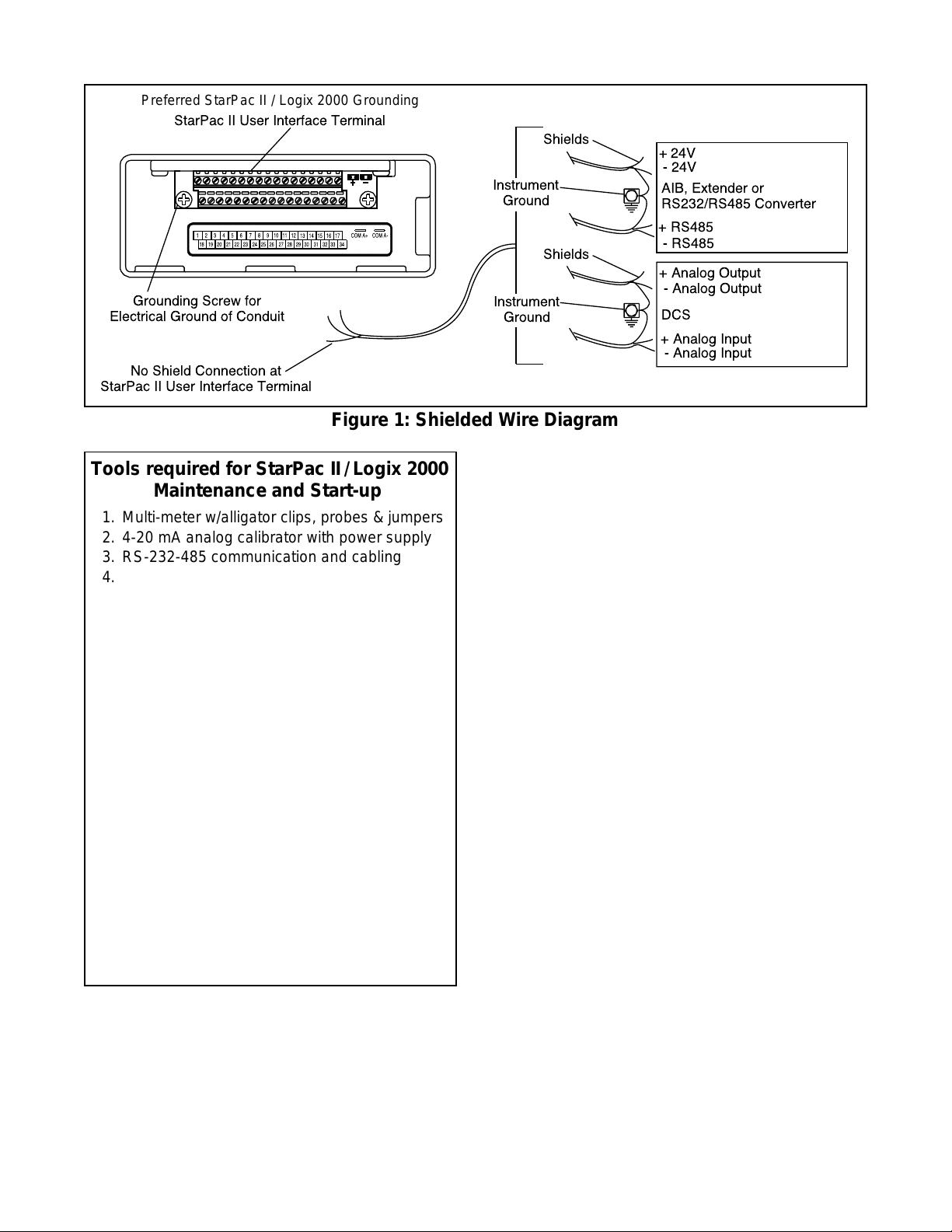
Preferred StarPac II / Logix 2000 Grounding
StarPac II User Interface Terminal
Grounding Screw for
Electrical Ground of Conduit
No Shield Connection at
StarPac II User Interface Terminal
Shields
Instrument
Ground
Shields
Instrument
Ground
Figure 1: Shielded Wire Diagram
+ 24V
- 24V
AIB, Extender or
RS232/RS485 Converter
+ RS485
- RS485
+ Analog Output
- Analog Output
DCS
+ Analog Input
- Analog Input
Tools required for StarPac II / Logix 2000
Maintenance and Start-up
1. Multi-meter w/alligator clips, probes & jumpers
2. 4-20 mA analog calibrator with power supply
3. RS-232-485 communication and cabling
4. Windows
TM
compatible PC
5. Standard 6-inch flat screwdriver
6. Standard phillips screwdriver
7.1/4-inch flat screwdriver
8. Small wire cutter (flush cut) & wire strippers
9. Needle-nose pliers
10.1/16-inch allen wrench
11. Vise grips
12. Small vise grips
13.1/2-inch nut driver
14.5/32-inch allen wrench
15. Large crescent wrench (minimum 15-inch)
16. 8-inch channel lock pliers
17.3/32-inch screwdriver
18. Wrist grounding strap
19. Antistatic bag or packaging
20. EPROM remover (PLCC type)
21. Electrical tape
22. Feedback shaft tool and drive module
pressure calibration connectors (supplied
with feedback module kit)
INSTALLATION
Valve Installation
The StarPac II / Logix 2000 Intelligent Control System
valve is installed in the same manner as a conventional
control valve and according to industry standards. Refer
to the appropriate valve installation, operation, maintenance instructions for proper installation procedures.
If the StarPac II is being installed in an insulated process
line, do not place more than four inches of insulation
around the pressure or temperature sensors; otherwise
the sensors may not operate properly. In addition,
NEVER
insulate the unit electronics assembly or
remote-mounted temperature/pressure sensors (when
used).
CAUTION: Do not insulate the StarPac II / Logix
2000 electronics housing or remote-mounted pressure or temperature sensors; otherwise excessive
heat may build up and affect operation.
Wiring and Grounding Guidelines
This section will help you achieve a maximum “noise -free”
environment and performance with a StarPac II / Logix
2000 unit.
Shielding Versus Grounding
All signals to the StarPac II / Logix 2000 unit should be
in shielded cables. Shields must be tied to a ground at
only one end of the cable to provide a place for environmental electrical noise to be removed from the cable. A
ground wire (unlike a shield) is attached at both ends to
provide a continuous path for electrical conductivity.
Grounding Screw
The green grounding screw by the user interface terminal block should be used to provide the unit with an
adequate and reliable earth ground reference. This
ground should be tied to the same ground as the
electrical conduit. Additionally, the electrical conduit
connecting to the unit should be earth grounded at both
ends of its run.
used to terminate signal shield wires.
24VDC Power
The 24 VDC connection points will work best with
shielded twisted pair wire with the shield wire connected
The green grounding screw must not be
42-2
Flowserve Corporation, Valtek Control Products, Tel. USA 801 489 8611
Page 3
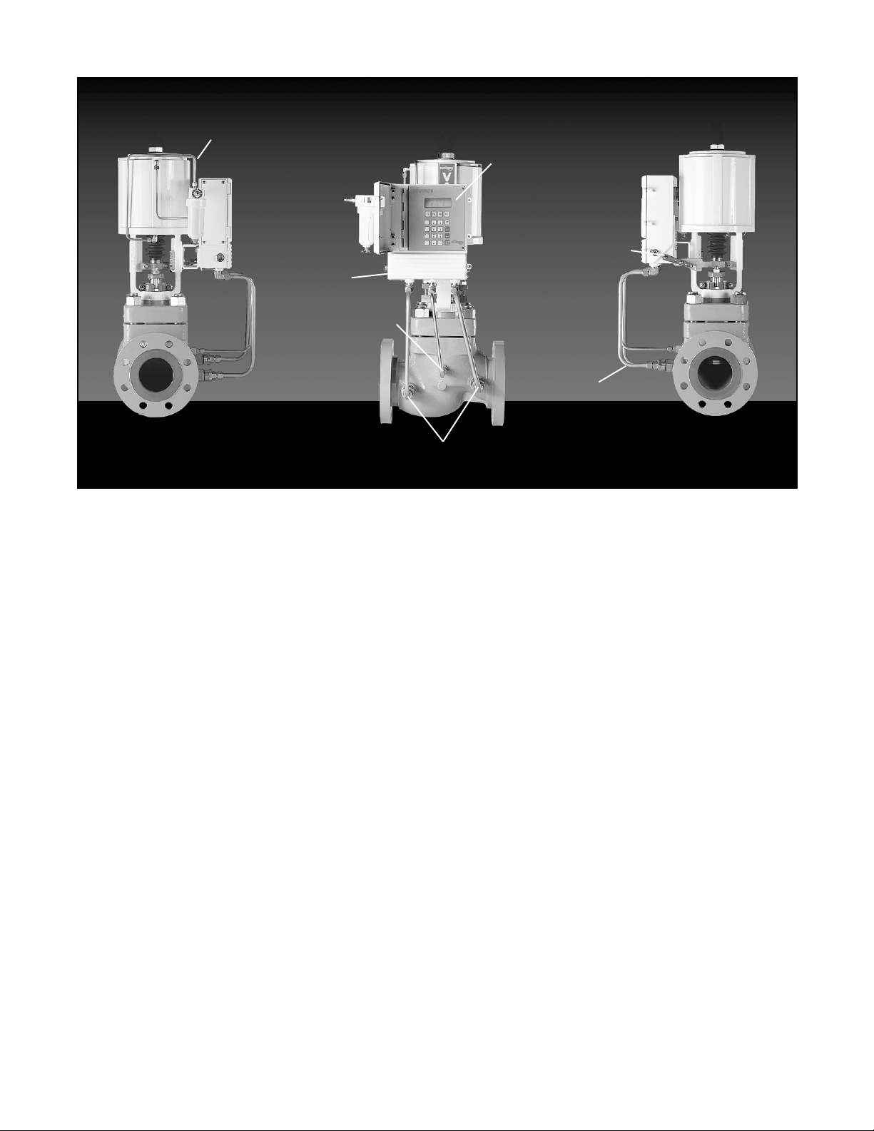
Air Lines to
Cylinder Actuator
Electronics Module
with Keypad and
Local Display
User Access
Terminal
Behind
Lower Door
Temperature
Sensor
Process Pressure Sensors
Figure 2: StarPac II / Logix 2000 Intelligent Control System Components
only at the source. The input power is isolated within the
unit and may be referenced to whatever level is necessary.
connected to earth ground.
RS-485 Communication
RS-485 wiring requires the use of a shielded twisted
pair cable, which is grounded only at the source and not
in the unit. (For maximum performance, wire should
have a characteristic impedance of 120 ohms.) The
RS-485 input is fully isolated, using opto-isolators.
The RS-485 allows only a 7 to 12 V common mode
voltage differential between stations. Valtek's RS-232
to RS-485 converter is not a grounded connection.
PC's with internal RS-485 cards, on the other hand, are
often grounded. If another ground communication
device is on the network, a fault condition will almost
certainly exist due to transient and steady state differences in ground potential.
4 - 20 mA Command Input, Auxiliary Input, and
Feedback Output
These signals are isolated but shielded twisted pair wire
should be used to reduce crosstalk from other signals.
The shield should be connected only at the source.
Discrete Inputs and Outputs
These signals are isolated, but because they are frequently used to switch high voltage (120 VAC), they
should be run in separate shielded wire paths away
from the other StarPac II / Logix 2000 signals.
The 24 VDC power supply should not be
Position
Feedback
Arm
Electronics
Conduit
AIB and RS-232 to RS-485 Converter Connection
When connecting a StarPac II / Logix 2000 unit to a
communication device, no shield or ground connections exist. Hence, the 24 VDC power and RS-485
communication shield drain wires must be connected to
a convenient ground near the AIB or converter.
Wiring The StarPac II / Logix 2000 System
All electrical connections must be done according to
local and industry electrical codes. Valtek recommends
a shielded cable be used for the RS-485 command
signal wire (e.g., Belden 9841 or equivalent).
When connecting multiple StarPac II / Logix 2000 units,
a parallel daisy-chain wiring pattern is used. Connect
unit's branch lines to main line, keeping branch lines as
short as possible. The total length of wiring should not
exceed 4,000 feet (1,200 meters) without use of repeaters.
Avoid devices producing electrical 'noise' while installing the cable.
CAUTION: The following procedure should be performed on the bench or with the unit isolated so that
unexpected valve stroking will not adversely affect
the process.
WARNING: The following procedures may cause
the valve to stroke, causing pressures and temperatures to vary from their norms. Notify appropriate personnel that the valve may stroke unexpectedly. Valtek suggests that the system be isolated
from the process, if installed in line.
Flowserve Corporation, Valtek Control Products, Tel. USA 801 489 8611
42-3
Page 4
1
2
3
52
48
46
44
45
11
50
49
47
59
60
62
55
53
51
83
61
58
57
56
54
42
43
29
31
80
81
30
32
33
35
82
8
7
36
37
34
38
40
41
64
68
12
69
72
71
70
73
76
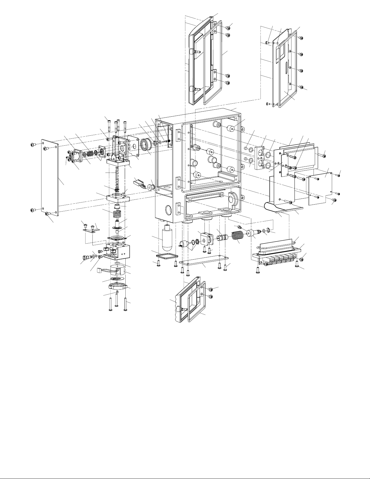
1. Upper door assembly
2. Door screw (4)
3. Upper door gasket
4. Lower door assembly
5. Door screw (2)
6. Lower door gasket
7. Inner door/keypad assembly
8. Inner door screw (4)
9. Feedback cover assembly
10. Cover screw (4)
11.Driver cover assembly
12. Cover screw (4)
13. Hydrophobic filter cover
14. Cover screw (2)
15. Hydrophobic filter
16. Hall potentiometer assembly
17. Potentiometer bracket
18. Flex couple
19. Bracket screws (2)
20. Torsional spring
21. Feedback shaft
22. Shaft O-ring
23. Retaining ring
24. Screw, hard stop
25. Feedthrough assembly
26. Feedthrough O-ring
27. Board screw (2)
28. Block screw (2)
63
65
66
67
74
75
77
78
79
29. Isolator (4)
30. Filter (2)
31. Adapter O-ring, lower (2)
32. Pressure sensor adapter
33. Adapter O-ring, upper (2)
34. StarPac II / Logix 2000
board assembly
35. Board stiffener
36. Board assembly screw (3)
37. Board stiffener screw
38. Board assembly screw (3)
39. Board assembly screw
40. Personality card
41. Personality card screw (4)
42. Rubber grommet (2)
43. Housing assembly
15
13
14
4
17
16
18
19
9
5
6
Figure 3: Exploded View
44. Regulator set screw
45. Regulator housing screw (4)
46. Regulator housing
47. Spring button
48. Regulator spring
49. Regulator diaphragm
assembly
50. Driver module mounting
screw (4)
51. Pilot valve
52. Pilot valve screw (4)
53. Pilot valve gasket
54. Regulator filter
55. Poppet guide
56. Poppet O-ring
57. Poppet
39
85
24
23
22
21
20
10
84
26
25
27
28
58. Poppet spring
59. Spool
60. Spool clip
61. Driver manifold O-ring
62. Driver spacer
63. Driver bearing
64. Spool return spring
65. Driver piston
66. Magnet
67. Driver manifold diaphragm
68. T-board screw (2)
69. T-board
70. Orifice screw
71. Orifice screw O-ring
72. Orifice O-ring
73. Testing plug (2)
74. Coil O-ring
75. Pressure modulator
assembly
76. Spring diaphragm
77. Modulator cover
78. Modulator set screw
79. Modulator screw (3)
80. Inner door screw (2)
81. Inner door screw O-ring (2)
82. Keypad gasket
83. Wire harness
84. 24-pin ribbon cable
85. 14-pin ribbon cable
42-4
Flowserve Corporation, Valtek Control Products, Tel. USA 801 489 8611
Page 5
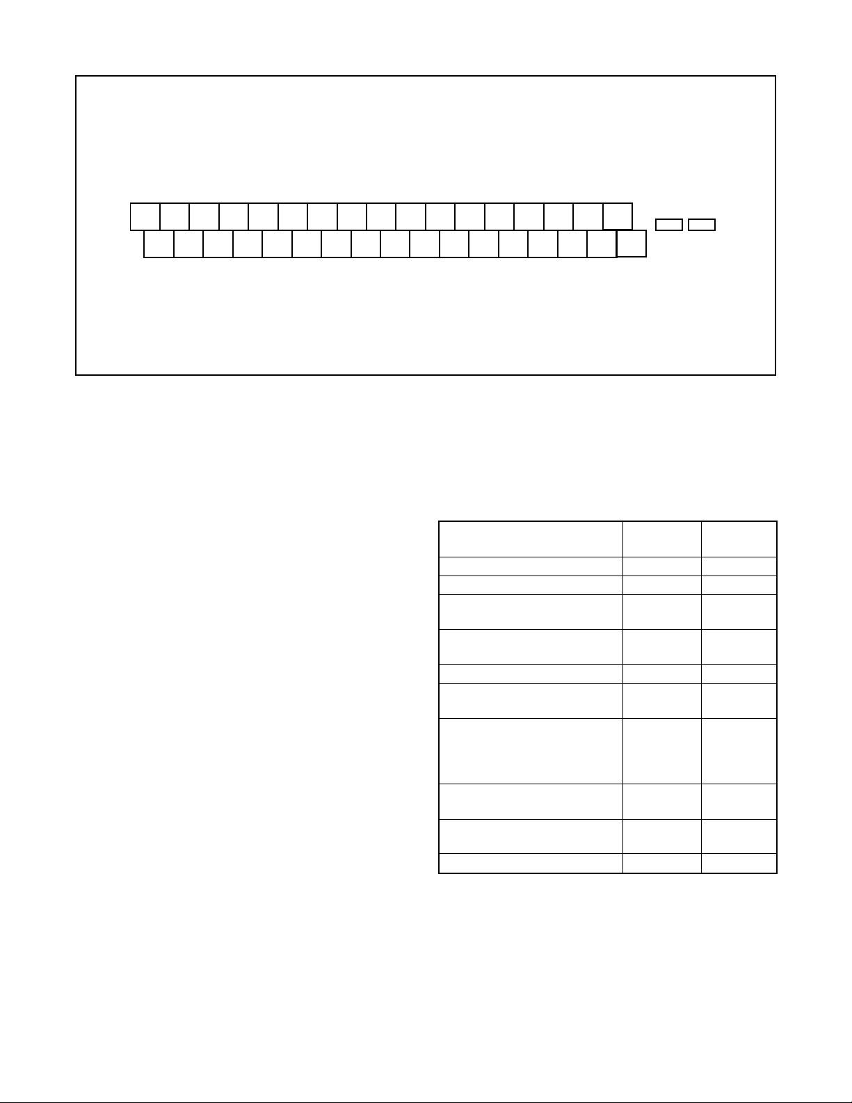
out -
out +
out -
1
1
Analog
out +
Analog
Spare
Com B -
Com B +
Com A -
Com A +
24 VDC -
24 VDC +
Grnd (Blk)
out - (Wht)
1
P
out + (Grn)
1
P
P
+5 VDC (Red)
1
1
P
Thrm Coup (Yel)
2
2
Thrm Coup (Red)
Analog
Analog
1 2 3 4 5 6 7 8 9 10 1112 131415 1617
18 19 20 21 22 23 24 25 26 27 28 29 30 31 32 33 34
Com A +
Com A -
Grnd (Blk)
out - (Wht)
2
P
out + (Grn)
2
P
P
in -
2
2
Analog
+5 VDC (Red)
2
P
in +
1
2
Analog
in -
in +
1
Analog
Analog
Spare
Figure 4: User Interface Terminal Pinouts
To connect the wiring to the StarPac II / Logix 2000 unit,
refer to Figures 1 and 4, and Table I, then proceed as
follows.
1. Open the lower door on the front of the housing.
WARNING: Do not open the electronic housing
covers in flammable atmospheres; otherwise,
possible injury to personnel or equipment may
occur.
2. Connect the required wires to the terminal interface
block and computer as described in Figure 4 and
Table I. (The system must have 24 VDC power for
operation.)
NOTE: The StarPac II / Logix 2000 unit remembers
the operating mode setting (automatic or manual)
from the last time the unit had power. When power
to the system is turned on again, the unit will resume
operation in the previous mode.
Normally the unit arrives from the factory set in the
manual analog operating mode. This means a
command signal will position the valve the same as
a traditional control valve, providing a plug position
proportional to the 4 - 20 mA signal.
To avoid upsetting the process because of improper
operating mode selection:
• Ensure that the system arrived from factory with
the proper operating mode setting in the shop prior
to installation by connecting air supply and command signal, then turning on the power and looking
at the mode value on the local display, or;
• Set the proper operating mode for the particular
application in the shop prior to installation by
selecting the desired operating mode from the
local interface or in the Tuning/Tune screen of the
StarTalk software, or;
Pulse Out
Pulse Out
Discrete 2 in
Discrete 2 in
Discrete 1 in
Alarm Contact
Alarm Contact
Discrete 1 in
• Ensure that the block valves in the process line
around the unit are closed and the process is
diverted around the unit.
Table I:
User Interface Terminal Connections
Signal Negative Positive
Term. No. Term. No.
24 VDC power 16 17
Valve command signal 24 25
Primary RS-485 14 15
communication link
Secondary RS-485 12 13
communication link
Auxiliary input (4-20 mA) 22 23
Analog output (4-20 mA) 1 9 10
Analog output (4-20 mA) 2 7 8
Discrete input 1 – switch/ 33 34
solenoid monitoring
(discrete mode source
input)
Discrete input 2 – switch/ 31 32
solenoid monitoring
Discrete output 1 (malfunc- 29 30
tion alarm contact)
Discrete output 2 (pulse) 27 28
3. Turn on the 24 VDC power to the unit, and verify that
it has been correctly wired by checking the following:
• 24 VDC power is at least 300 mA and between 18.0
and 64.0 VDC
• Polarity is correct
• Local display is on; if not, check the power supply.
4. Close the front cover on the housing of the unit.
Flowserve Corporation, Valtek Control Products, Tel. USA 801 489 8611
42-5
Page 6
System Communication Default
Configuration
StarPac II / Logix 2000 units are shipped from the factory
ready for installation and operation. Rarely do the units
need to be re-configured prior to operation. Table II lists
the factory default communication settings. If these
settings are not correct for the equipment being used,
proceed to the following sections.
Table II: Factory Default Mode Settings
Description Setting
Address 1
Parity odd
Baud Rate 19,200
Modbus Communication Mode RTU
RS-485 Termination Resistors Installed
Termination
Jumpers
Selecting Correct Address Setting
If the StarPac II / Logix 2000 unit is the only one on the
communication network, the default address (1) is fine.
If multiple units will be operating on the same communication network, each unit must have a unique address.
Before changing the address, the StarTalk software can
be used to determine what devices are on the line.
(Remember to include devices that may be temporarily
off line.)
If the default address setting needs to be changed, use
the 'Comm' option in the configuration menu of the local
interface to change the settings.
Selecting Correct Baud Rate Setting
StarPac II / Logix 2000 units support baud rates of up to
57,600 baud. However, both the StarPac II / Logix 2000
system and StarTalk software are shipped from the
factory set to 19,200 baud.
If the default baud rate setting needs to be changed, use
the 'Comm' option in the configuration menu of the local
interface to change the settings.
Selecting Correct Modbus Transmission
Mode
Two transmission modes exist in a Modbus system,
ASCII and RTU (default). Use the ASCII mode when
transmitting information through a device that uses
ASCII control codes; for example, a modem. Use the
RTU mode when connecting directly to both devices; for
example, an RS-485 interface card wired directly to a
StarPac II / Logix 2000 system.
If the default Modbus transmission mode setting needs
to be changed, use the 'Comm' option in the configuration menu of the local interface to change the settings.
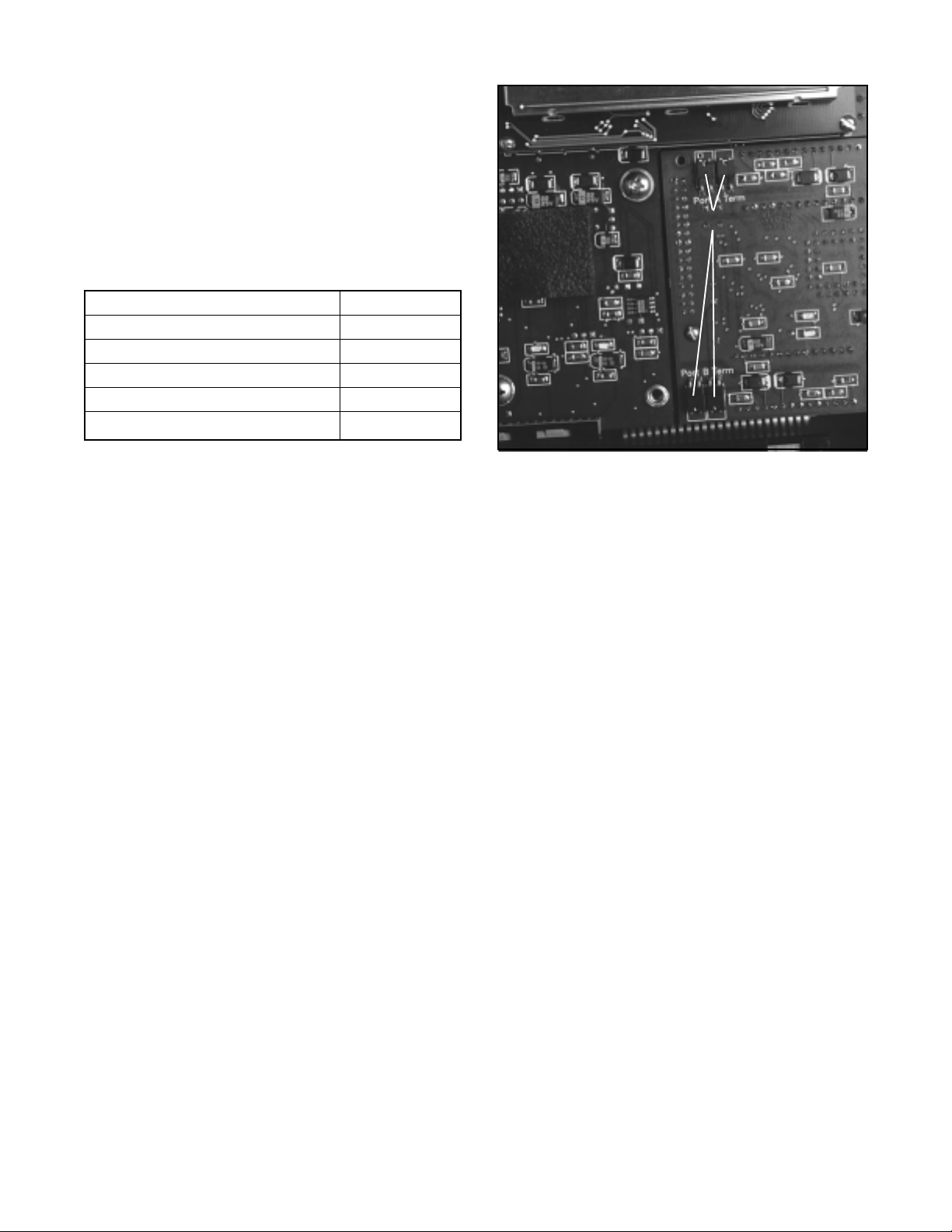
Figure 5: Termination Jumpers and
Personality Module
Selecting Proper RS-485 Termination
Resistor Setting
A termination resistor must be installed on the two most
remote devices on the network, counting the host
computer as any other device.
(For example, a single StarPac II / Logix 2000 unit and
the RS-485 driver in the host computer would each
require the termination resistor to be installed. If four
units were on the network with a host computer, decide
which of the two devices have the most combined cable
length between them. These two devices should have
the termination resistors installed. The termination
resistors should be disabled in the devices not considered to be the most remote using the instructions in the
next section. Using more than two termination resistors
in a network can cause the RS-485 communications to
operate erratically or fail.)
To enable 120 ohms termination, insert both jumpers
for A and B channels. To disable termination, remove
both jumpers from each channel as shown in
Figure 5.
SYSTEM MAINTENANCE
Valtek recommends that the StarPac II / Logix 2000
system calibration be checked every six months. If,
after checking the unit, a component is determined to
be defective, the following section will help with the
component replacement.
The following items may be needed to install, start up
and calibrate the unit's electronics.
42-6
Flowserve Corporation, Valtek Control Products, Tel. USA 801 489 8611
Page 7

• Power supply: 24 VDC, 300 mA
• Digital volt meter with 4 - 20 mA range
• Air supply: 50 psig minimum, 80-100 psig preferred
• Gauges or the ability to accurately determine pro-
cess pressures and valve air supply pressures
• 4 - 20 mA command source
• Thermocouple calibrator or simulator with 0 to 500°
Celsius range
8. Turn on the air supply to the valve and check for
leaks in the reattached actuator tubing lines.
9. Turn on power to the unit. Check the system
calibration and perform a Valve Stroke Calibration
to reset the position feedback. Refer to the Calibration section of the StarPac II / Logix 2000 manual.
StarPac II / Logix 2000 Positioner
Overview
Mechanical Subsystem Maintenance
Refer to the appropriate Valtek Installation, Operation &
Maintenance (IOM) instructions for details on repair and
maintenance of the control valve actuator components.
Please refer to the manufacturers’ manuals for maintenance and operation instructions for non-pneumatic
actuators, e.g., electric or electro-hydraulic actuators.
WARNING: The process line must be depressurized
and drained of process fluid and decontaminated
prior to working on internal valve components. Failure to do so may cause serious injury to personnel.
1. Depressurize the line, decontaminate the valve (if
needed) and shut off the air supply to the valve
positioner.
2. Disconnect the actuator air tubes from the unit.
3. Disconnect the two mounting bolts that attach the
StarPac II / Logix 2000 system bracket.
4. Disconnect the follower arm from the unit base.
This is done by removing the follower arm nut and
washer and pulling the arm off the shaft. Notice that
this shaft connection is keyed and that the shafts
are slightly spring loaded.
5. The actuator subassembly is now isolated and is
removed by loosening the bonnet bolts and lifting
the actuator away from the body.
The tubing holds the StarPac II / Logix 2000 base in
place, eliminating the need to disconnect wiring or
air connections.
6. Standard valve maintenance may now be done on
the actuator or valve body components. Refer to
the Valtek IOM instructions for details on such
things as trim or packing replacement. If you have
to replace the trim, use the same trim number and
characteristic as the original trim so the flow calculations are not affected. If a trim size change is
needed, contact your Valtek representative to find
out about flow characterization options.
7. Reassemble the system by reversing the above
steps. Be sure to follow the procedures outlined in
the Valtek IOM instructions for valve reassembly.
When reconnecting the follower arm, make sure
that the arm fits correctly on the keyed shaft and has
a positive spring action.
The StarPac II / Logix 2000 is double-acting, capable of
supplying air to either side of the actuator piston while
exhausting the other side to the atmosphere. Also, the
positioner can be mounted on either Valtek linear or
rotary actuators without modification to the actuator.
The positioner is pending non-incendive for class I,
division II, groups A, B, C, and D; class II, groups E,
F, and G. Since the positioner is insensitive to supply
pressure changes and can handle supply pressures
from 30 to 150 psig, a supply regulator is usually not
required; however, an air filter is required due to the
close tolerances of the spool assembly.
NOTE: The air supply should conform to ISA
Standard S7.3 (a dew point at least 18° F below
ambient temperature, particle size below 5 microns,
oil content not to exceed 1 part per million).
Positioner Operation
The StarPac II / Logix 2000 Positioner is an electric
feedback instrument. Figure 6 shows a StarPac II
installed on a double-acting actuator for air-to-open
action. Positioning is based on a balance of two signals:
one proportional to the modulator input signal and the
other proportional to the stem position.
The supply pressure for the positioner modulator is
tapped off the main supply and is filtered as it passes
through a field-replaceable, coalescing filter element in
the module. Next it passes through an internal pressure
regulator that regulates it to approximately 22 psig. The
air then goes through an orifice that restricts the flow
and air consumption (refer to Figure 6).
The air is further controlled to 6-12 psig using a springdiaphragm flapper that is attracted by an electromagnet
to a nozzle. A temperature compensated hall effect
sensor mounted on a circuit board senses the spool
valve position. The hall effect sensor and circuitry
create a feedback loop, which determines how much
current to send to the electromagnet for a desired spool
valve position. The electromagnet in the feedback loop
varies the nozzle-flapper spacing, which regulates the
output pressure to 6-12 psig proportional to the command input signal.
When these opposing signals are equal, the system will
be in equilibrium and the stem will be in the position
called for by the command signal. If these opposing
Flowserve Corporation, Valtek Control Products, Tel. USA 801 489 8611
42-7
Page 8
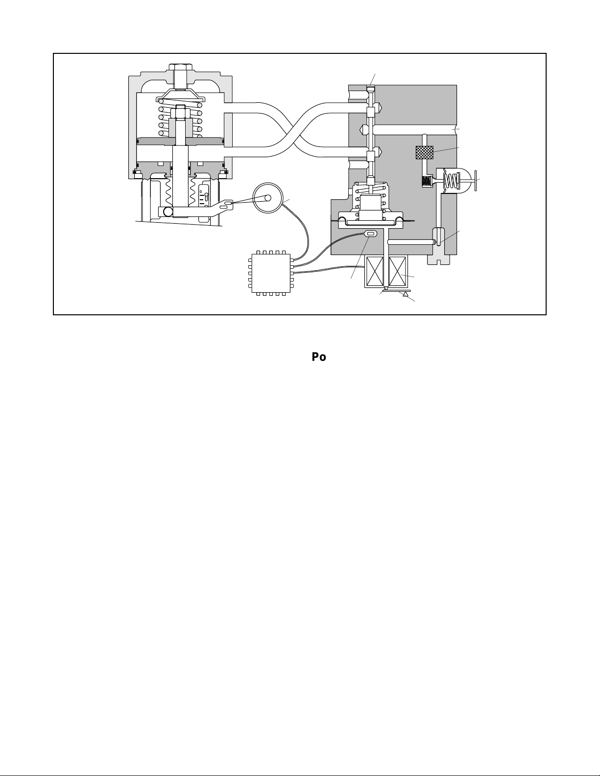
Exhaust
Output 1
Pilot Valve Spool
Air Supply
OO
Air-to-open
Configuration
Digital
Position
Algorithm
Figure 6: Positioner Diagram
signals are not equal, the spool valve will move up (or
down) and, by means of the modulator, will change the
output pressures and flow rate. This will cause the
piston to move until the signal of the feedback sensor
equalizes with the command signal.
The detailed sequence of positioner operations are as
follows: An increase in the command signal forces the
modulator signal capsule and spool valve upward. This
motion of the modulator also pushes the pilot valve
spool upward from its equilibrium position. This opens
the pilot valve ports, supplying air to port one and
exhausting air from port two. This causes the actuator
piston to move upward.
This upward motion of the piston is transmitted back to
the positioner through the feedback linkage and hallpot
sensor signal changing proportionally to the valve position. The piston continues to stroke upward until the
signal of the feedback sensor increases sufficiently to
counter the signal being sent to the modulator. At this
point, the spool is at its equilibrium position as the
pressures in the cylinder stabilize and the air flow to the
actuator decreases.
After the piston has reached the required position, the
feedback signal will equal the spool position generated
in the modulator capsule. The computer will then make
small null adjustments to fine-tune the desired position
and compensate for changes in dynamic loading.
A decrease in the command signal reverses the described actions causing a proportional downward movement of the actuator piston and stem.
Output 2
Exhaust
Stem Position
Sensor
Spool Position
Sensor
Nozzle
Electromagnetic Coil
Flapper
Filter
Regulator
Orifice
Position Feedback System
The position feedback linkage of the StarPac II / Logix
2000 system is a critical part of the system. This linkage
is also used in the StarPac II to calculate the valve’s C
for a given stroke for flow measurement. This linkage
should be lubricated and checked periodically for tight,
smooth operation. The follower arm should operate
smoothly with no binding and have a positive spring
loading on the arm. Inspect the follower arm pin for
excess wear and replace if needed. The take-off arm
attached to the stem clamp must be firmly secured to
the stem clamp and perpendicular to the actuator stem.
If this takeoff arm is canted or misaligned, problems
may occur with positioner calibration and the position
reading on the unit may go out of range.
On rotary actuators, make sure the adjustment linkage
locknut is tight and has no excessive play in the ball
joints. The rotary shaft clamp must be tight and should
not freely rotate on the shaft.
Pressure Sensor Replacement
Standard StarPac II pressure sensors are typically installed directly into the control valve body. Before they
can be removed, the process line must be depressurized
and drained of all fluids and the valve decontaminated.
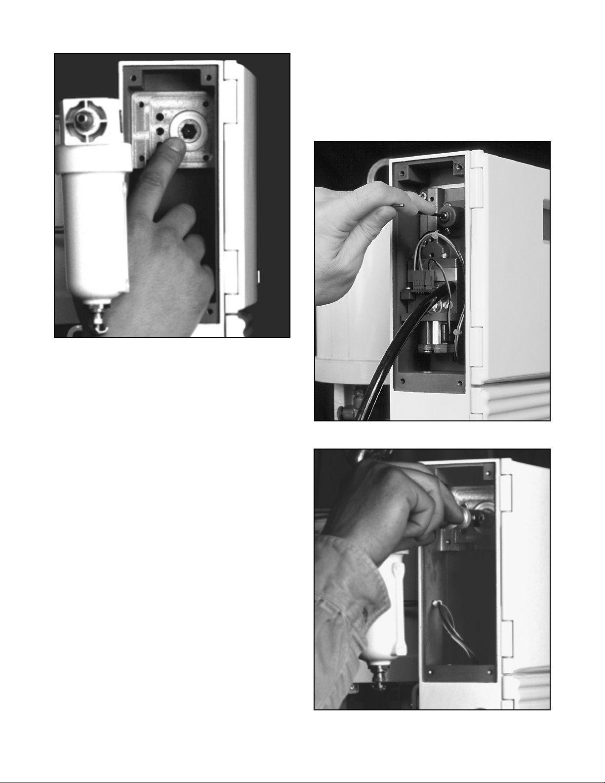
To replace a pressure sensor, refer to Figure 7 then
proceed as follows.
WARNING: The process line must be depressurized
and drained of process fluid, and decontaminated
prior to working on internal valve components. Failure
to do so may cause serious injury to personnel.
V
42-8
Flowserve Corporation, Valtek Control Products, Tel. USA 801 489 8611
Page 9

Figure 7: Disconnecting Lemo Connector
WARNING: If the pressure sensors are remotemounted, the sensor will be located in a sensor
housing in the tubing line and not in the sensor
housing located on the valve body. This section
of the tubing contains process fluid and must be
drained and decontaminated before the sensor is
removed. The procedure for sensor removal and
replacement will be similar to that outlined below.
(Refer to alternate sensor information when this type of
sensor is included with system.)
1. Depressurize and decontaminate the line and valve.
Loosen the tubing nuts on the conduit leading to the
pressure sensor, if applicable.
2. Loosen the sensor nut.
3. Gently pull the conduit and sensor nut approximately 1/2 to 0.75-inch from the sensor. Use needle
nose pliers to release the locking sleeve of the
Lemo™ connector by moving the collar away from
the sensor and disconnect the connector from the
sensor. Swing the sensor conduit out of the way
(refer to Figure 7).
4. Unscrew the sensor from the sensor boss.
5. Remove the sensor O-ring or gasket and replace
with a new one. Make sure the environmental
O-ring seal is in good condition and in place on the
new sensor.
6. Install the new sensor into the sensor port making
sure the O-ring or gasket remains properly in place
while tightening the sensor. Tighten the sensor
until it seats metal-to-metal at the gasket section of
the sensor port, ensuring the proper compression
of the process O-ring or gasket seal.
7. Align the red dots on the sensor and connector,
and reconnect the Lemo connector. Fully seat the
connector until the locking sleeve latches. Replace
the sensor nut and tighten.
8. Pressurize the valve body to make sure the sensors
are properly seated before attaching the sensor
conduit and tightening.
9. Reattach the conduit lines and securely tighten the
fittings.
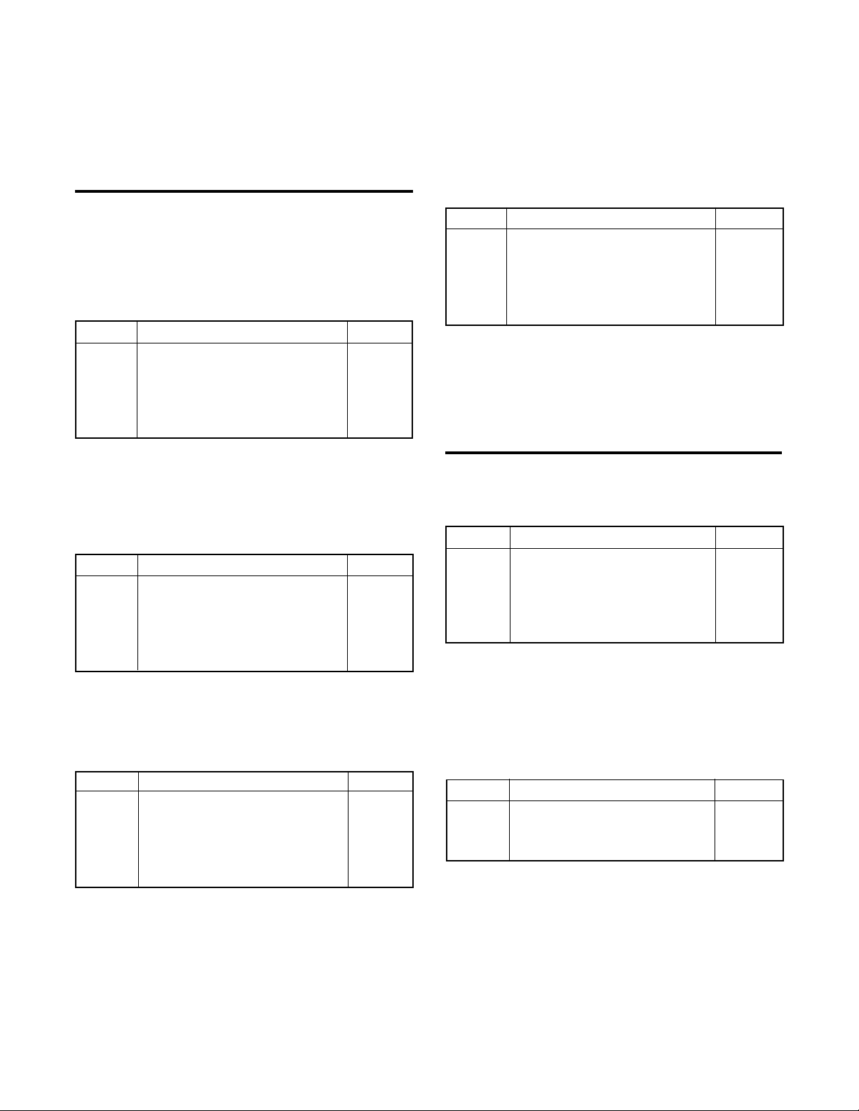
Figure 8: Thermocouple Replacement
Thermocouple Replacement
In normal configuration, the thermocouple does not
penetrate the valve body wall. Depressurizing the body
is not necessary
NOTE: If the StarPac II was ordered with a special
thermocouple option, verify the need to depressurize
the body before proceeding.
1. Disconnect power and air supply to the unit.
2. Open the lower terminal block cover and disconnect the red and yellow thermocouple wire.
3. Loosen the tubing nuts on both ends of the thermocouple assembly (refer to Figure 8).
4. Pull the wires out of the StarPac base and slip the
tubing off the wires.
5. Unscrew the old thermocouple from the body.
6. Install the new thermocouple.
7. Feed the wires back through the tubing and into the
StarPac housing.
8. Tighten the tubing nuts.
9. Cut the thermocouple wires to length. Strip and
reattach wires to the terminal block, noting color
polarity. (The red wire is the negative signal.)
10.Check that all the fittings are tight.
when replacing the thermocouple.
Flowserve Corporation, Valtek Control Products, Tel. USA 801 489 8611
42-9
Page 10

Keypad Assembly Replacement
If, after consulting with the local Valtek or factory representative, the StarPac II / Logix 2000's keypad is found
to be defective and needs replacement, refer to Figure
3 and proceed as follows.
1. Make sure valve is by-passed and in a safe condition.
2. Disconnect the power and air supply to the unit.
3. Undo the two captive screws securing the upper
door to the housing and open the upper door.
4. Undo the two screws securing the inner door to the
housing and swing the inner door completely open.
5. Carefully disconnect the keypad connector from the
board stack.
6. Remove the four hinge mounting screws and remove the inner door.
7. Install the new keypad assembly in reverse order.
Note: When installing a new keypad assembly,
check for proper door alignment before final lockdown of hinge-mounting screws.
Feedback Assembly Replacement
If it is determined that the Feedback Assembly needs
replacement, refer to Figures 3 and 9 then proceed as
follows: (New feedback assembly is preset at the factory.)
1. Make sure valve is by-passed or in a safe condition.
2. Disconnect the power and air supply to the unit.
3. Disconnect the positioner pin and follower arm from
the feedback shaft.
4. Remove the four feedback cover screws and
remove the cover.
5. Disconnect the three-pin connector from the hallpot
while observing the connector orientation.
6. Remove the two potentiometer bracket screws.
7. Remove the retaining ring from the feedback shaft.
8. Thread the feedback shaft tool (provided in the
replacement kit) onto feedback shaft and push
shaft out of bushing (refer to Figure 9).
9. Remove feedback shaft tool and feedback assembly.
10. To install the new feedback assembly, lightly grease
the feedback shaft and apply thread locking compound to the two potentiometer bracket mounting
holes. Slide the feedback assembly into the feedback bushing.
11. Thread on the feedback shaft tool and push while
turning clockwise, aligning the stroke-stop screw
and stop boss. Next, pull back to the seat stop on
the housing (refer to Figure 9).
12. Remove the feedback shaft tool and install the
retaining ring in the feedback shaft.
13. Using two mounting screws, fasten the potentiometer
bracket to the housing, making sure the feedback
assembly is aligned and the flex couple is engaged.
14. Reconnect the three-pin connector to the hallpot (in
orientation as noted above).
15. Replace the feedback cover and four cover screws.
Then perform a stroke calibration.
Figure 9: Feedback Shaft Tool
Regulator Filter Replacement
To replace the regulator filter, refer to Figures 3 and 10
then proceed as follows:
1. Make sure valve is by-passed or in a safe condition.
2. Disconnect the power and air supply to the unit.
3. Remove the four driver module cover screws and
set the cover aside.
4. Disconnect the four-pin connector from the T-board,
observing the connector orientation.
5. Remove the four driver module mounting screws
and remove the driver module.
6. Carefully remove the pilot valve gasket by peeling
or scraping.
7. Remove the old regulator filter and insert the new
filter (refer to Figure 10).
8. Remove the backing on the pilot valve gasket to
expose the adhesive and apply the pilot valve
gasket to the housing, making sure that the holes
are aligned.
9. Apply thread locking compound to the four mounting holes and fasten the driver module to the housing with the four mounting screws.
10. Reconnect the four-pin connector to the T-board in
the orientation as noted above.
11. Replace the driver module cover with the four cover
screws.
42-10
Flowserve Corporation, Valtek Control Products, Tel. USA 801 489 8611
Page 11
13. Apply thread locking compound to the four mount-
ing holes and fasten the driver module to the housing using the four mounting screws.
14. Reconnect the four-pin connector to the T-board in
the same orientation as noted above.
15. Replace the driver module cover and cover screws.
Figure 10: Regulator Filter Replacement
Driver Module Assembly Replacement
To replace the driver module assembly, refer to Figures
3, 10, 11, and 12 then proceed as follows:
1. Make sure valve is by-passed or in a safe condition.
2. Disconnect the power and air supply to the unit.
3. Remove the four driver module cover screws and
set the cover aside.
4. Disconnect the four-pin connector from the T-board,
observing the connector orientation.
5. Remove the four driver module mounting screws
and remove the driver module. (Check the pilot
valve and poppet assemblies for wear or deterioration. If needed, continue with steps 6-12. If cleaning only, refer to Spool Valve Assembly Replacement then proceed to step 13 after cleaning.)
6. Carefully remove the pilot valve gasket by peeling
or scraping.
7. Remove the poppet guide, poppet O-ring, poppet,
and poppet spring.
8. Remove and replace the regulator filter.
9. Insert the new poppet spring into the housing poppet hole.
10. Place the O-ring on the poppet seat.
11. Thread the poppet guide and poppet into the housing and tighten to 6-inch/lbs. maximum (refer to
Figure 12).
12. Remove the backing from the pilot valve gasket to
expose the adhesive and apply the gasket to the
housing, making sure the holes are aligned.
Figure 11: Setting Regulator Pressure
Figure 12: Poppet Guide Installation
Flowserve Corporation, Valtek Control Products, Tel. USA 801 489 8611
42-11
Page 12

Driver Module Calibration
1. Hook power supply (24 VDC) leads to StarPac II /
Logix 2000 connector numbers 16 and 17.
2. Hook up supply pressure to the unit, using the port
marked S.
3. Remove the upper port plug from the Driver Manifold and screw the pressure test fitting into the port.
4. Set the regulator pressure to 22 psig, plus or minus
0.5 psig by adjusting the set screw on the regulator
(refer to Figure 11).
5. Remove the test fitting and replace it with the port
plug ensuring that the seal washer is present.
6. Remove the lower port plug from the Driver Manifold and screw the pressure test fitting into the port.
7. Set the Modulator pressure to 2 psig, plus or minus
0.25 psig by adjusting the set screw on the bottom
of the modulator cap (refer to Figure 13).
8. Remove the test fitting and replace it with the port
plug, making sure the seal washer is present.
9. Proceed with the positioner calibration routine. First,
edit register 40157 to put in a value of 2750 for the
null adjust. The valve should be set to be 50 percent
open during these calibrations and adjustments.
This typically takes several minutes to complete.
Replacing the Electronic Boards
The StarPac II / Logix 2000 has two main electronic
boards, one personality module, and one terminal strip
mounted inside the housing. The two boards are
located behind the keypad door of the housing, mounted
one atop the other in a stacked fashion. The personality
module is plugged into the lower right hand corner of the
boards.
If, after consulting with a local Valtek or factory representative, and determination is made that the electronic
boards need replacement, proceed as follows.
1. Make sure the valve is by-passed or in a safe position.
Follow handling procedures that protect the boards
from the static electricity and ground currents.
2. To access the board stack, open the housing door.
Undo the two screws that fasten the keypad door to
the housing and swing out the keypad door (the
stacks will be visible). Because the factory places
a serial number on each stack, the board stack
should be kept together as one unit. Mixing boards
with other stacks is not recommended.
3. The top board consists of a main section and a
smaller, removable personality card on the lower
right corner. The size of this card is about two
square inches. The card contains the programming
logic and is sometimes removed for software customizing. Remove the card by undoing the four
small screws holding it to the top board. Carefully
lift it out, as it is also held in place by a board-toboard connector. Transport this card in a static
resistant pouch.
4. To install the personality card, align the board-toboard connector and press straight in. Reinstall the
four screws. (Any time the version of the personality module is changed, re-initialize the system by
holding down the zero (0) button while turning the
24V power on – then releasing once the display is
legible. The unit will be in test mode and must be
reconfigured for proper operation.)
Figure 13: Setting Modulator Pressure
42-12
The Board Stack
1. Disconnect the power and air supply to the unit
before removing the electronic board stack. The
two pressurized pneumatic ports connect directly
with two board mounted pressure sensors. A total
of eight screws hold down the boards. The screw
with an allen head should not be removed. The
other seven are phillips head-type and can be
removed. Note that one of the seven phillips screws
is located on the lower right portion of lower board.
2. Undo the seven phillips screws and the board stack
will lift away from the housing. Disconnect the
connectors from the boards. Carefully undo the
integral clips as you pull the connector away from
the board (refer to Figure 14).
Flowserve Corporation, Valtek Control Products, Tel. USA 801 489 8611
Page 13

A
Discrete Jumpers
Figure 15: Discrete Jumpers Under
Personality Module
Figure 14: Replacing the Board Stack
3. Transport the board stack in a static resistant pouch.
4. To reinstall the new stack, reverse the above procedure. (Be careful to align the pins on the interconnection connector as you install the connectors.)
CAUTION: When sliding the new board stack in
place, push gently on the connector strip to slip
it behind the screw boss before installing the
lower left-hand screw of the board stack. Failure to do this will cause the strip (A, Figure 15)
to be pinched between the boss and board,
leading to damage of the connector strip.
Table III: MaxFlo Rotary Actuator
Mounting Kits
Actuator Shaft Size Air To Mounting
Size Kit
25 0.4375 Open 10059457
25 0.4375 Close 10059457
25 0.625 Open 10059458
25 0.625 Close 10059458
25 0.875 Open 10059460
25 0.875 Close 10059460
50 0.875 Open 10059473
50 0.875 Close 10059472
50 1.125 Open 10059477
50 1.125 Close 10059476
100 1.5 Open 10059481
100 1.5 Close 10059480
200 1.5 Open 10094609
200 1.5 Close 10094608
Mounting kit includes bracket, linkage assembly , follower
arm,and all necessary nuts, bolts and washers.
Discrete Jumpers
Three sets of jumpers (Figure 15) are located on the
main circuit board underneath the personality module.
These jumpers are used to configure the operation of
discrete inputs and outputs. These are labeled Relay,
DI 1, and DI 2.
The relay jumper allows selection of normally open
(N.O.) and normally closed (N.C.) forms of the alarm
contacts (A-B=N.O. and B-C=N.C.). DI 1 and DI 2
allows selection of the input voltage range for the two
discrete input channels. (A-B=60-120V input range,
B-C=20-48V input range.)
Note: Both jumpers on each of these blocks must be
moved to the desired position for proper operation.
Caution: Do not apply high voltage when low
voltage sensing is selected. Damage will occur.
Table IV: Linear Actuator Mounting Kits
Actuator Stroke Spud Mounting
Size (inches) (inches) Kit
25 0.5 - 1.5 2.00 10007189
50 0.5 - 3 2.00 10062174
50 0.5 - 3 2.62 10007191
100 3 2.62 - 2.88 10007192
100 4 3.38 - 4.75 10007193
200 1 - 4 2.88 10054278
200 1.5 - 4 3.38 - 4.75 1005428
300 1 - 4 3.38 - 4.75 10054284
Mounting kit includes bracket, stem clamp, follower arm,
follower pin, and all necessary nuts, bolts and washers.
Flowserve Corporation, Valtek Control Products, Tel. USA 801 489 8611
42-13
Page 14

Figure 16: Sensor Troubleshooting Chart
42-14
Flowserve Corporation, Valtek Control Products, Tel. USA 801 489 8611
Page 15

Troubleshooting StarPac II / Logix 2000 Systems
Failure Probable Cause Corrective Action
Local display not on 1. 24 VDC not on or set correctly 1. Verify power supply is outputting 24 VDC
(terminals 16 and 17)
2. Incorrect wiring polarity 2. Check wiring for correct polarity
3. Interface connections on bottom 3. Make sure connections are correctly
are not correct aligned and fully plugged in
Erratic communications 1. Multiple units have same address 1. Change each unit to a unique, sequential
on network line address (refer to Address Setting in
Maintenance section)
2. Proper polarity not maintained 2. Check all network connections for cor-
rect positive and negative connections
3. Individual units not properly wired 3. Begin with shortest RS-485 run, check-
ing polarity and communication; continue
checking units throughout network
4. Termination jumpers not installed 4. Install termination jumper on two most
distant devices
The unit does not 1. Unit still in initialize mode 1. Put unit in operation mode
respond to analog 2. Select analog input
commands
StarPac II / Logix 2000 1. Improper configuration file was 1. Find the correct file for this system and
data is not correct loaded onto system load onto the unit
Valve position reading 1. Hallpot connection not tight 1. Tighten hallpot connection set screw
is not correct 2. Stroke not calibrated 2. Calibrate valve stroke
3. Hallpot shaft is not at correct 3. Readjust hallpot shaft connection,
part of rotation making sure that as the shaft rotates
the output signal is always increasing
as valve opens
Stem position decreas- 1. Hallpot wiring harness is installed 1. Reverse three-wire harness
es when valve opens backwards
2. Hallpot shaft is not on correct arc 2. Readjust hallpot shaft connection,
making sure that as the shaft rotates,
the output signal is always increasing
as valve opens
Sticking or hunting 1. Contamination of the spool valve 1. Check air supply for proper filtering and
operation of the assembly meeting ISA Specification S7.3.
positioner 2. Clean spool valve assembly with a non-
residue cleaner.
StarPac II/Logix 2000 Electronics Initialization Procedure
To re-initialize the electronics:
1. Turn OFF the 24V power.
2. Press and hold down the ZERO (0) key on the keypad while turning the 24V power ON
3. Release the key after the display has booted and is active (approx. 5 seconds)
The following conditions are set upon re-initialization. Those items that have been previously configured by
the user may need to be reconfigured when the unit is put back into operation:
• Mode source is set to Digital
• Data Logger is disabled
• Test mode is set
• Process variable = Liquid Flow
• Command source = Analog
• Positioner Source = Normal
• Positioner Gain is reset to 25 in˝ actuator
Flowserve Corporation, Valtek Control Products, Tel. USA 801 489 8611
• Analog Feedback = Position
• PID action = Normal
• Air Action = Air-To-Open
• Totalizer is reset
• Modbus address is set to 1
• Communications is set to 19200 baud, Odd parity, RTU mode
42-15
Page 16

StarPac II and Logix Series 2000 Spare Parts Kits
See Figure 3: StarPac II / Logix 2000 Exploded View for item numbers.
Kit 1 - Upper Door Assembly
Part No. 10060956
Item No. Description Quantity
1 Upper door assembly 1
2 Door screw 4
3 Upper door gasket 1
Kit 2 - Lower Door Assembly
Part No. 10060958
Item No. Description Quantity
4 Lower door assembly 1
5 Door screw 2
6 Lower door gasket 1
Kit 3 - Key Pad Assembly
Part No. 10060978
Item No. Description Quantity
7 Inner door / keypad assembly 1
8 Inner door hinge screws 4
80 Inner door screw 2
81 Inner door screw O-ring 2
Kit 4 - Feedback Assembly*
Part No. 10060981
Item No. Description Quantity
16 Hall potentiometer assembly 1
17 Potentiometer bracket 1
18 Flex coupler 1
19 Bracket screw 2
20 Torsional spring 1
21 Feedback shaft 1
22 Shaft O-ring 1
23 Retaining ring 1
24 Hard stop screw 1
*NOTE: Feedback shaft tool included in kit. Assembly
comes pre-set from factory.
Kit 5 - Regulator Filter Replacement Kit
Part No. 10060988
Item No. Description Quantity
50 Driver module mounting screw 4
53 Pilot valve gasket 1
54 Regulator filter 1
Kit 6 - Driver Module Assembly*
Part No. 10060991
Item No. Description Quantity
44 Regulator set screw 1
45 Regulator housing screw 4
46 Regulator housing 1
47 Spring button 1
48 Regulator spring 1
49 Regulator diaphragm assembly 1
50 Driver module mounting screw 4
51 Pilot valve 1
52 Pilot valve screw 4
53 Pilot valve gasket 1
54 Regulator filter 1
55 Poppet guide 1
56 Poppet O-ring 1
57 Poppet 1
58 Poppet spring 1
59 Spool 1
60 Spool clip 1
61 Driver manifold O-ring 1
62 Driver spacer 1
63 Driver bearing 1
64 Spool return spring 1
65 Driver piston 1
66 Driver magnet 1
67 Driver manifold diaphragm 1
68 T-board screw 2
69 T-board 1
70 Orifice screw 1
71 Orifice screw O-ring 1
72 Orifice O-ring 1
73 Testing plug 2
74 Coil O-ring 1
75 Pressure modulator assembly 1
76 Spring diaphragm 1
77 Modulator cover 1
78 Modulator set screw 1
79 Modulator screw 3
*NOTE: Regulator and modulator are shipped factory
calibrated.
42-16
Flowserve Corporation, Valtek Control Products, Tel. USA 801 489 8611
Page 17

Kit 7 - StarPac II/Logix 2000 Electronics Board
Assembly
Part No. 10055130
Item No. Description Quantity
31 Adapter O-ring, lower 2
32 Pressure Sensor adapter 1
33 Adapter O-ring, upper 2
34 StarPac II board assembly 1
35 Board stiffener 1
36 Board assembly screw 3
37 Board stiffener screw 1
38 Board assembly screw 3
39 Board assembly screw 1
40 Personality card with EPROM 1
41 Personality card screw 4
84 24-pin ribbon cable 1
85 14-pin ribbon cable 1
Kit 8 - Personality Card, Modbus Communications
Part No. 10061003
Kit 13 - Soft Goods Kit
Part No. 10061007
Item No. Description Quantity
3 Upper door gasket 1
6 Lower door gasket 1
22 Shaft O-ring 1
29 Isolator 4
31 Adapter O-ring, lower 2
33 Adapter O-ring, upper 2
42 Rubber grommet 2
49 Regulator diaphragm assembly 1
53 Pilot valve gasket 1
56 Poppet O-ring 1
61 Driver manifold O-ring 1
67 Driver manifold diaphragm 1
71 Orifice screw O-ring 1
72 Orifice O-ring 1
73 Test plug 2
74 Coil O-ring 1
81 Inner door screw O-ring 2
Item No. Description Quantity
40 Personality card with EPROM 1
41 Personality card screw 4
Kit 9 - 24-pin Ribbon Cable
Part No. 10202746
Item No. Description Quantity
84 24-pin ribbon cable 1
Kit 10 - 14-pin Ribbon Cable
Part No. 10010221
Item No. Description Quantity
85 14-pin ribbon cable 1
Kit 11 - Standard Wire Harness Assembly
Part No. 10061008
Item No. Description Quantity
42 Rubber grommet 2
83 Wire harness assembly 1
Kit 12 - Wire Harness Assembly, Sealed
(Natural Gas Service)
Not shown in Figure 3
Part No. 10061012
Item No. Description Quantity
83 Wire harness assembly 1
Kit 14 - Driver Cover Assembly
Part No. 10061018
Item No. Description Quantity
11 Driver cover assembly 1
12 Cover screw 4
Kit 15 - Feedback Cover Assembly
Part No. 10061019
Item No. Description Quantity
9 Feedback cover assembly 1
10 Cover screw 4
Kit 16 - Door Gasket Replacement Kit
Part No. 10061384
Item No. Description Quantity
3 Upper door gasket 1
6 Lower door gasket 1
82 Keypad gasket 1
Kit 17 - External Air Filter Replacement
Part No. 10053002
Description Quantity
Coalescing air filter 1
Kit 18 - Follower Arm Pin for Linear Actuators
Part No. 10036685
Flowserve Corporation, Valtek Control Products, Tel. USA 801 489 8611
Description Quantity
Follower pin for linear actuators 1
42-17
Page 18

Table V: Valdisk Rotary Actuator
Mounting Kits
Actuator Shaft Size Air To Mounting
Size Kit
25 0.625 Open 10059458
25 0.625 Close 10059458
25 0.75 Open 10059459
25 0.75 Close 10059459
25 0.875 Open 10059460
25 0.875 Close 10059460
50 0.625 Open 10059461
50 0.625 Close 10059462
50 0.75 Open 10059463
50 0.75 Close 10059471
50 0.875 Open 10059472
50 0.875 Close 10059473
50 1.125 Open 10059476
50 1.125 Close 10059477
100 0.875 Open 10059474
100 0.875 Close 10059475
100 1.125 Open 10059478
100 1.125 Close 10059479
100 1.5 Open 10059480
100 1.5 Close 10059481
100 1 0.75 Open 10059482
100 1 0.75 Close 10059483
200 1.125 Open 10094606
200 1.125 Close 10094607
200 1.5 Open 10094608
200 1.5 Close 10094609
200 1 0.75 Open 10094610
200 1 0.75 Close 10094611
Mounting kit includes bracket, linkage assembly ,
follower arm, and all necessary nuts, bolts and
washers.
T able VI: StarPac Accessories
Description Number
Converter, RS232/RS485, 110/220 VAC 10055963
StarPac Analog Interface (8 Channel),
24 VDC 10069207
Power supply, DIN rail mounted,
110 VAC to 24 VDC 10079519
Table VII: Valdisk 150 Rotary Actuator
Mounting Kits
Actuator Shaft Size Air To Mounting
Size Kit
25 0.625 Open 10059458
25 0.625 Close 10059458
25 0.875 Open 10059460
25 0.875 Close 10059460
50 0.625 Open 10059461
50 0.625 Close 10059462
50 0.875 Open 10059472
50 0.875 Close 10059473
50 1.0625 Open 10059484
50 1.0625 Close 10059486
50 1.34375 Open 10059489
50 1.34375 Close 10059490
100 0.875 Open 10059474
100 0.875 Close 10059475
100 1.0625 Open 10059487
100 1.0625 Close 10059488
100 1.34375 Open 10059492
100 1.34375 Close 10059495
100 1.375 Open 10059496
100 1.375 Close 10059504
100 1.5 Open 10059480
100 1.5 Close 10059481
100 1 0.75 Open 10059482
100 1 0.75 Close 10059483
200 1.0625 Open 10094612
200 1.0625 Close 10094613
200 1.34375 Open 10094614
200 1.34375 Close 10094615
200 1.375 Open 10094616
200 1.375 Close 10094617
200 1.5 Open 10094608
200 1.5 Close 10094609
200 1 0.75 Open 10094610
200 1 0.75 Close 10094611
Mounting kit includes bracket, linkage assembly ,
follower arm, and all necessary nuts, bolts and
washers.
T able VIII: Completed Assemblies
Description Number
StarPac II assembly 10007028
Logix 2000 assembly 10053635
42-18
Flowserve Corporation, Valtek Control Products, Tel. USA 801 489 8611
Page 19

Table IX: ShearStream Rotary Actuator Mounting Kits
Shaft Size Air To / Shaft Mounting 25 Actuator 50 Actuator 100 Actuator 200 Actuator
Open / Up Right (Std) 10059457
Left 10059457
Close / Up Right (Std) 10059457
0.4375
0.625
0.75
0.875
1.125
1.5
10.75
Close / Down Right (Std) 10059457
Open / Down Right (Std) 10059457
Open / Up Right (Std) 10059458 10059461
Close / Up Right (Std) 10059458 10059462
Close / Down Right (Std) 10059458 10059461
Open / Down Right (Std) 10059458 10059462
Open / Up Right (Std) 10059459 10059463
Close / Up Right (Std) 10059459 10059471
Close / Down Right (Std) 10059459 10059463
Open / Down Right (Std) 10059459 10059471
Open / Up Right (Std) 10059460 10059472 10059474
Close / Up Right (Std) 10059460 10059473 10059475
Close / Down Right (Std) 10059460 10059472 10059474
Open / Down Right (Std) 10059460 10059473 10059475
Open / Up Right (Std) 10059476 10059478 10094606
Close / Up Right (Std) 10059477 10059479 10094607
Close / Down Right (Std) 10059476 10059478 10094606
Open / Down Right (Std) 10059477 10059479 10094607
Open / Up Right (Std) 10059480 10094608
Close / Up Right (Std) 10059481 10094609
Close / Down Right (Std) 10059480 10094608
Open / Down Right (Std) 10059481 10094609
Open / Up Right (Std) 10059482 10094610
Close / Up Right (Std) 13359483 10094611
Close / Down Right (Std) 10059482 10094610
Open / Down Right (Std) 13359483 10094611
Mounting kit includes bracket, linkage assembly, follower arm, and all necessary nuts, bolts and washers.
Left 10059457
Left 10059457
Left 10059457
Left 10059458 10059462
Left 10059458 10059461
Left 10059458 10059462
Left 10059458 10059461
Left 10059459 10059471
Left 10059459 10059463
Left 10059459 10059471
Left 10059459 10059463
Left 10059460 10059473 10059475
Left 10059460 10059472 10059474
Left 10059460 10059473 10059475
Left 10059460 10059472 10059474
Left 10059477 10059479 10094607
Left 10059476 10059478 10094606
Left 10059477 10059479 10094607
Left 10059476 10059478 10094606
Left 10059481 10094609
Left 10059480 10094608
Left 10059481 10094609
Left 10059480 10094608
Left 13359483 10094611
Left 10059482 10094610
Left 13359483 10094611
Left 10059482 10094610
Flowserve Corporation, Valtek Control Products, Tel. USA 801 489 8611
42-19
Page 20
Pressure and Temperature Sensor Spare Part Kits
See Body Mount Sensor Configurations Drawing and Remote Mount Sensor
Configuration Drawing for item numbers.
Pressure Sensor Gasket Kits
NOTE: Kits 1 thru 4 will service two body or two remote-
mount pressure sensors from any one of the pressure
sensor configuration drawing numbers listed below
each table.
Kit 1 - Viton O-ring Replacement Kit
Part No. 10061027
Item No. Description Quantity
6 Environmental O-ring, Viton 2
8 Environmental O-ring, Viton 4
10 O-ring seal, Viton 2
20 Environmental O-ring, Viton 2
21 O-ring seal, Viton 2
Configuration Drawing Numbers: 83883, 83891,
83904, 83884, 83892, 101565, 83887 83900,
127586, 83888, 83901
Kit 2 - Spiral Wound Gasket Replacement Kit
Part No. 10061028
Item No. Description Quantity
6 Environmental O-ring, Viton 2
8 Environmental O-ring, Viton 4
10 O-ring seal, Viton 2
20 Environmental O-ring, Viton 2
21 Spiral wound gasket seal 2
Configuration Drawing Numbers: 83938, 83890,
122670, 83886, 83903, 127563, 83899, 127632
Kit 4 - Kalrez O-ring Replacement Kit
Part No. 10061113
Item No. Description Quantity
6 Environmental O-ring, Viton 2
8 Environmental O-ring, Viton 4
10 O-ring seal, Kalrez
20 Environmental O-ring, Kalrez 2
21 O-ring seal, Kalrez 2
Configuration Drawing Numbers: 83885, 83889,
127665, 83893, 83902
™
2
Pressure Sensor Hardware Kits
Kit 5 - Pressure Sensor Connection Kit, Div II
Non-incendive Configuration
Part No. 10061022
Item No. Description Quantity
3 Swagelok nut 2
4 Swagelok ferrules 2
5 Sensor nut 2
6 Environmental O-ring, Viton
7 Division II sensor fitting 2
NOTE: Kit will service two pressure sensors.
For class I, Division II, Group A, B, C, & D.
See Table XIII for Tubing.
®
2
Kit 3 - PTFE Gasket Replacement Kit
Part No. 10061029
Item No. Description Quantity
6 Environmental O-ring, Viton 2
8 Environmental O-ring, Viton 4
10 PTFE gasket seal 2
20 Environmental O-ring, Viton 2
21 PTFE gasket seal 2
Configuration Drawing Numbers: 122513, 127565
42-20
Kit 6 - Pressure Sensor Connection Kit, Div I
Configuration
Part No. 10061023
Item No. Description Quantity
13 Division I sensor fitting 2
5 Sensor nut 2
6 Environmental O-ring, Viton 2
NOTE: Kit will service two pressure sensors.
For class I, Division I, Groups B, C, & D.
Flowserve Corporation, Valtek Control Products, Tel. USA 801 489 8611
Page 21

Kit 7 - Remote Mount Pressure Sensor Hardware Kit
Part No. 10061025
Item No. Description Quantity
3 Swagelok nut 4
4 Swagelok ferrules 4
15 Temperature extended fitting 2
19 Adapter fitting 2
NOTE: Kit will service two remote-mount pressure
sensors. See Table XIII for tubing. (Wet-leg tubing
wall thickness must be 0.065-inch).
Kit 8 - Remote Mount Pressure Sensor Hardware
Kit with Purge and Isolation Valves
Part No. 10061026
Item No. Description Quantity
3 Swagelok nut 4
4 Swagelok ferrules 4
15 Temperature extended fitting 2
16 Purge valve 2
17 Isolation valve 2
19 Adapter fitting 2
NOTE: Kit will service two remote-mount pressure
sensors. See Table XIII for tubing. (Wet-leg tubing
wall thickness must be 0.065-inch).
Kit 12 - Pressure Sensor Calibration Kit
Part No. 10061118
Description Quantity
Pressure sensor calibration fixture 1
Electrical connector extension cable 2
O-ring seal, Viton 2
NOTE: Two sensors can be calibrated simultaneously with this kit.
Kit 13 - DP Cell Manifold Replacement
Part No. 10203723
Description Quantity
Valve manifold 1
Temperature Probe Kits
See temperature sensor configurations drawing for
item numbers.
Kit 14 - Standard Temperature Probe
Replacement, Div II Configuration
Part No. 10055955
Item No. Description Quantity
2 Standard temperature probe 1
Kit 9 - Explosion Proof Union Fitting
Part No. 10007238
Item No. Description Quantity
14 Explosion proof union 1
Kit 10 - Pressure Sensor Electrical Cable
Replacement Kit
Part No. 10061117
Item No. Description Quantity
1 Electrical connector cable 2
22 Four-pin connector 2
23 Wire crimp terminal 16
NOTE: Kit will service two pressure sensors.
Kit 11 - Pressure Sensor Electrical Extension Cable
Part No. 10054518
Description Quantity
Electrical connector extension cable 1
Kit 15 - Standard Temperature Probe
Replacement, Div I Configuration
Part No. 10070891
Item No. Description Quantity
2 Standard temperature probe 1
6 Adapter fitting 1
7 Adapter fitting 1
Kit 16 - Through Hole Temperature Probe
Replacement
Part No. 10065272
Item No. Description Quantity
2 Through hole temperature probe 1
Flowserve Corporation, Valtek Control Products, Tel. USA 801 489 8611
42-21
Page 22

12
11
10
Boss on
valve body
8
13
6
5
14
1
9
8
1. Electrical connection cable
2. Tubing, 0.035 wall thickness (see Table XIII)
3. Swagelock nut
4. Swagelock ferrule set
5. Sensor nut
6. Environmental O-ring
7. Division II sensor fitting
8. Environmental O-ring
9. Pressure sensor
10. O-ring seal
11. Length adapter fitting
Figure 17: Body-mount Sensor Configurations
This table is a combination of Kit 17 and Table XI.
Table X: Pressure Sensor Accessories
Description Number
PTFE cap for flush-mount sensors 10203061
Pressure sensor length adapters
w/Viton O-rings, 10070892
Pressure sensor length adapters
w/spiral-wound gaskets 10070893
NOTE: On July 1993, the sensor manufacturer
shortened the process end of the pressure sensors.
If the StarPac uses the longer style sensors, order
one of the above adapter kits with the new sensor
purchase. Each kit will service two pressure sensors.
4
3
7
2
6
5
12. O-ring seal
13. Division I sensor fitting
14. Explosion-proof union
15. Wire crimp terminals
16. Four-pin connector
15
16
Table XI: Flush Mount Pressure Sensor
Diaphragm
Description
Hastelloy C
Pressure sensor, 0-25 PSIA, flush 10103511
Pressure sensor, 0-50 PSIA, flush 10103512
Pressure sensor, 0-100 PSIA, flush 10103514
Pressure sensor, 0-150 PSIA, flush 10103516
Pressure sensor, 0-300 PSIA, flush 10103519
Pressure sensor, 0-500 PSIA, flush 10103521
Pressure sensor, 0-1000 PSIA, flush 10103522
NOTE: Flush mount sensors are not rated for Division I applications.
Material
42-22
Flowserve Corporation, Valtek Control Products, Tel. USA 801 489 8611
Page 23

Boss on
valve body
12
11
21
20
22
23
4
5
2
3
6
7
8
13
6
9
5
14
16
15
4
3
19
1
4
3
8
10
18
17
4
3
18
1. Electrical connector cable
2. Tubing 0.035-inch wall, (see T able XIII)
3. Swagelock nut
4. Swagelock ferrule set
5. Sensor nut
6. Environmental O-ring
7. Division II sensor fitting
8. Environmental O-ring
9. Pressure sensor
10. O-ring seal
11. Length adapter fitting
12. O-ring seal
13. Division I sensor fitting
14. Explosion-proof union
3
4
15. Temperature extended fitting
16. Purge valve
17. Isolation valve
18. Wet-leg tubing, 0.065-inch wall, (see T able XIII)
19. Adapter fitting
20. Environmental O-ring
21. O-ring seal
22. Four-pin connector
23. Wire crimp terminals
Figure 18: Remote-mount Sensor Configurations
Table XII: Standard Pressure Sensor
Description
Pressure sensor, 0-25 PSIA 10062971
Pressure sensor, 0-50 PSIA 10062972
Pressure sensor, 0-100 PSIA 10062957
Pressure sensor, 0-150 PSIA 10062963
Pressure sensor, 0-300 PSIA 10062974
Pressure sensor, 0-500 PSIA 10062965
Pressure sensor, 0-1000 PSIA 10062960
Pressure sensor, 0-1500 PSIA 10062975
Pressure sensor, 0-3000 PSIA 10062977
Pressure sensor, 0-5000 PSIA 10062978
Pressure sensor, 0-7500 PSIA 10091198
NOTE: Hastelloy C sensors are not rated for Division I applications.
Diaphragm Material
316 Stainless steel
Flowserve Corporation, Valtek Control Products, Tel. USA 801 489 8611
42-23
Page 24

4
Temperature probe boss
3
Div II Configuration
2
1
7
2
146
5
Div I Configuration
1. T wo-pin connector
2. Temperature probe
3. T ubing, 0.035 wall, (see Table XIII)
4. Swagelock tube fitting
5. Stainless steel pipe
6. Adapter fitting
7. Adapter fitting
14. Explosion-proof union
Figure 19: StarPac Temperature Sensor, Flush-mount Version
Table XIII: 316 Stainless Steel Tubing
Description Number
Pressure sensor wire tubing (0.50-inch diameter 0.035-inch thick) 10045503
Temperature extended wet leg tubing (0.50-inch diameter 0.065-inch thick) 10055784
I/P wire and thermocouple tubing (3/8-inch diameter, 0.035-inch thick) 10013367
1
On remote mount pressure sensor configurations, the wet-leg tubing must have a wall thickness of 0.065-inch.
Flowserve Corporation has established industry leadership in the design and manufacture of its products. When properly selected, this Flowserve product is designed to perform its
intended function safely during its useful life. However, the purchaser or user of Flowserve products should be aware that Flowserve products might be used in numerous applications
under a wide variety of industrial service conditions. Although Flowserve can (and often does) provide general guidelines, it cannot provide specific data and warnings for all possible
applications. The purchaser/user must therefore assume the ultimate responsibility for the proper sizing and selection, installation, operation and maintenance of Flowserve products.
The purchaser/user should read and understand the Installation Operation Maintenance (IOM) instructions included with the product, and train its employees and contractors in the safe
use of Flowserve products in connection with the specific application.
While the information and specifications presented in this literature are believed to be accurate, they are supplied for informative purposes only and should not be considered certified or
as a guarantee of satisfactory results by reliance thereon. Nothing contained herein is to be construed as a warranty or guarantee, express or implied, regarding any matter with respect
to this product. Because Flowserve is continually improving and upgrading its product design, the specifications, dimensions and information contained herein are subject to change
without notice. Should any question arise concerning these provisions, the purchaser/user should contact Flowserve Corporation at any of its worldwide operations or offices.
For more information, contact:
Flowserve and Valtek are registered trademarks of Flowserve Corporation.
FCD VLAIM042-03 © 2000 Flowserve Corporation. Flowserve Corporation, Valtek Control Products, Tel. USA 801 489 8611
For more information about Flowserve, contact www.flowserve.com or call USA 972 443 6500
Regional Headquarters
1350 N. Mt. Springs Prkwy.
Springville, UT 84663
Phone 801 489 8611
Facsimile 801 489 3719
12 Tuas Avenue 20
Republic of Signapore 638824
Phone (65) 862 3332
Facsimile (65) 862 4940
12, av. du Québec, B.P. 645
91965, Courtaboeuf Cedex,
France
Phone (33 1) 60 92 32 51
Facsimile (33 1) 60 92 32 99
Quick Response Centers
5114 Railroad Street
Deer Park, TX 77536 USA
Phone 281 479 9500
Facsimile 281 479 8511
104 Chelsea Parkway
Boothwyn, PA 19061 USA
Phone 610 497 8600
Facsimile 610 497 6680
1300 Parkway View Drive
Pittsburgh, PA 15205 USA
Phone 412 787 8803
Facsimile 412 787 1944
 Loading...