

Fisher & Paykel OR36LDBGX1, OR36LDBGX Installation Instructions Manual

1
US CA
OR36LDBGX model
Installation instructions
Freestanding range
Instructions d'installation
Cuiseur indépendant
2
✓ Do not store or use gasoline or other flammable vapors and liquids
in the vicinity of this or any other appliance.
✓ WHAT TO DO IF YOU SMELL GAS:
• Do not try to light any appliance.
• Do not touch any electrical switch; do not use any phone in your
building.
• lmmediately call your gas supplier from a neighbor's phone.
Follow the gas supplier's instructions.
• lf you cannot reach your gas supplier, call the fire department.
✓ Installation and service must be performed by a qualified installer,
service agency, or the gas supplier.
WARNING: IF THE INFORMATION IN THIS MANUAL IS NOT
FOLLOWED EXACTLY, A FIRE OR EXPLOSION MAY RESULT
CAUSING PROPERTY DAMAGE, PERSONAL INJURY, OR
This appliance is designed and manufactured solely for the cooking of domestic (household)
food and in not suitable for any none domestic application and therefore should not be used
in a commercial environmement.
The appliance guarantee will be void if the appliance is used within a non domestic
environnement i.e. a semi commercial, commercial or communal environment.
This range is supplied with a protective film on steel and aluminium parts.
This film must be removed before installing/using the appliance.
FOR INSTALLER ONLY
THIS RANGE IS FOR RESIDENTIAL USE ONLY
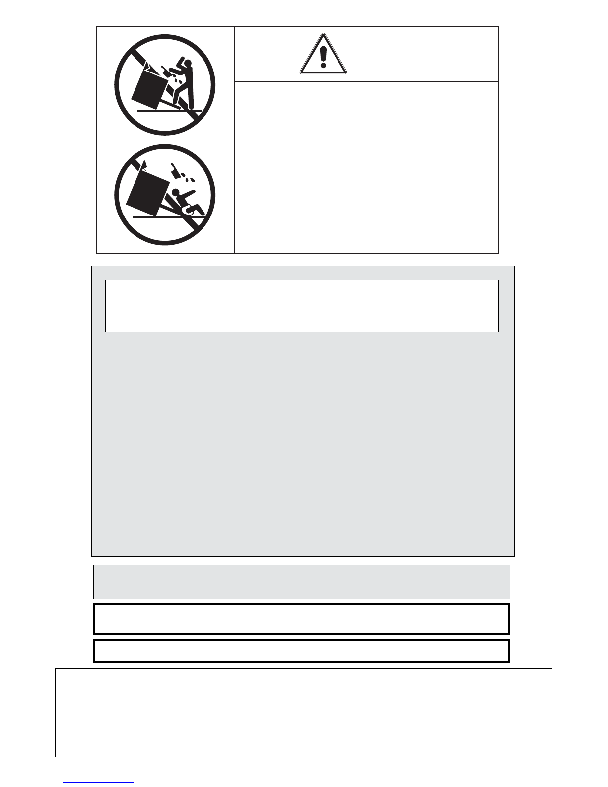
WARNING
• ALL RANGES CAN TIP
• INJURY TO PERSON COULD RESULT
• INSTALL ANTI-TIP DEVICE PACKED
WITH RANGE
• SEE INSTALLATION INSTRUCTIONS
3
IMPORTANT - PLEASE READ AND FOLLOW
✓ Before beginning, please read these instructions completely and
carefully.
✓ Do not remove permanently affixed labels, warnings, or plates
from the product. This may void the warranty.
✓ Please observe all local and national codes and ordinances.
✓ Please ensure that this product is properly grounded.
✓ The electrical plug should always be accessible.
✓ The installer should leave these instructions with the consumer who should retain for local inspec-
tor's use and for future reference.
Installation must conform with local codes or in the absence of codes, the National Fuel Gas Code ANSIZ223.1
- Iatest edition. Electrical installation must be in accordance with the National Electrical Code, ANSI/NFPA70
- latest edition and/or local codes. IN CANADA: Installation must be in accordance with the current CAN/
CGA-B149.1 National Gas Installation Code or CAN/CGA-B149.2, Propane Installation Code and/or local
codes. Electrical installation must be in accordance with the current CSA C22.1 Canadian Electrical Codes
Part 1 and/or local codes.
INSTALLATION IN MANUFACTURED (MOBILE) HOME: The installation must conform with the Manufactured
Home Construction and Safety Standard, Title 24 CFR, Part 3280 [formerly the Federal Standard for Mobile
Home Construction and Safety, Title 24, HUD (Part 280)] or, when such standard is not applicable, the
Standard for Manufactured Home Installations, ANSI/NCSBCS A225.1, or with local codes where applicable.
INSTALLATION IN RECREATIONAL PARK TRAILERS: The installation must conform with state or other codes
or, in the absence of such codes, with the Standard for Recreational Park Trailers, ANSI A119.5.
Installation of any gas-fired equipment should be made by a Iicensed plumber. A manual gas shut-off valve
must be installed in the gas supply line ahead of the appliance in the gas stream for safety and ease of service.
If an external electrical source is utilized, the appliance, when installed, must be electrically grounded in
accordance with local codes or, in the absence of local codes, with the national Electrical Code, ANSI/NFPA
70.
DATA PLATE
CONVERSION LABEL
4
WARNING!
THIS APPLIANCE HAS TO BE INSTALLED BY A QUALIFIED INSTALLER.
Improper installation, adjustment, alteration, services, or maintenance can cause injury or property damage. Consult a
qualified installer, service agent, or the gas supplier.
IMPORTANT: The use of suitable protective clothing/gloves is recommended when handling, installing of this appliance.
INSTALLATION INSTRUCTIONS
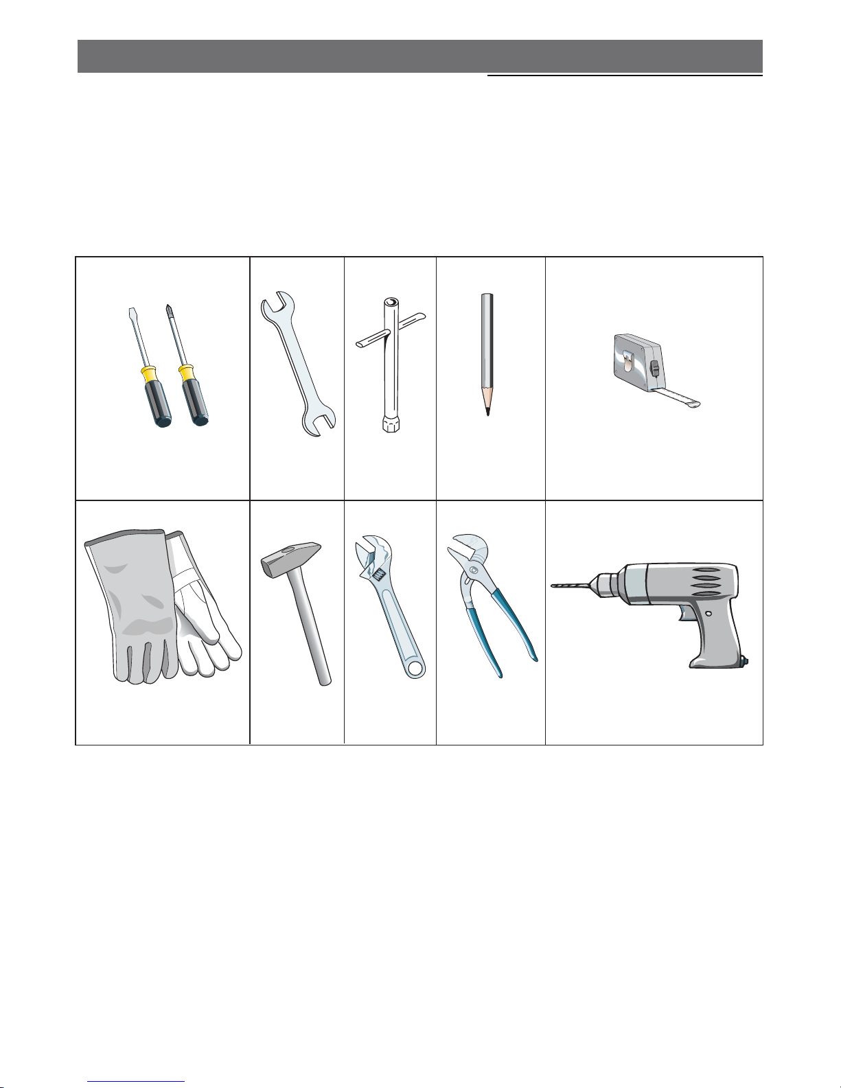
TOOLS NEEDED FOR INSTALLATION
Screwdriver 2 - Wrench
T-handle
wrench
Tape
measurePencil
Adjustable
pliers
Adjustable
wrench
Suitable protective
gloves
Drill
Hammer
5
GENERAL INFORMATION
1. Installation must conform with local codes or, in the
absence of local codes, with the National Fuel Gas Code,
ANSI Z223.1-Latest Edition.
2. Installation in manufactured (mobile) home: installation
must conform with the Manufactured Home Construction
and Safety Standard, Title 24 CFR, Part 3280 [formerly
the Federal Standard for Mobile Home Construction and
Safety, Title 24, HUD (Part 280)] or, when such standard
is not applicable, the Standard for Manufactured Home
Installations, ANSI/NCSBCS A225.1, or with local codes
where applicable.
3. Installation in Recreational Park Trailers: installation must
conform with state or other codes or, in the absence of
such codes, with the Standard for Recreational Park
Trailers, ANSI A119.5.
4.
WARNING!!
This appliance shall not be used for space heating. This
information is based on safety considerations.
5. AlI openings in the wall behind the appliance and in the floor
under the appliance shall be sealed.
6. Keep appliance area clear and free from combustible
materials, gasoline, and other flammable vapors.
7. Do not obstruct the flow of combustion and ventilation air.
8. Disconnect the electrical supply to the appliance before
servicing.
9. When removing appliance for cleaning and/or service;
A. Shut off gas at main supply.
B. Disconnect AC power supply.
C. Disconnect gas line to the inlet pipe.
D. Carefully remove the range by pulling outward.
CAUTION: Range is heavy; use care in handling.
10.
Electrical Requirement
Electrical installation should comply with national and local
codes.
11.
Air Supply and Ventilation
The installer must refers to local/national codes.
12. Gas Manifold Pressure
Natural gas - 4.0” W.C.P.
LP/Propane - 11.0” W.C.P.
13. The misuse of oven door (e.g. stepping, sitting, or leaning
on them) can result in potential hazards and/or injuries.
14. When installing or removing the range for service, a rolling
lift jack should be used. Do not push against any of the
edges of the range in an attempt to slide it into or out of
the installation. Pushing or pulling a range (rather than using
a lift jack) also increases the possibility of bending the leg
spindles or the internal coupling connectors.
WARNING!!
ELECTRICAL GROUNDING INSTRUCTIONS
The range must be electrically grounded in accordance
with local codes or, in the absence of local codes, with the
National Electrical Code, ANSI/NFPA No. 70-latest edition.
Installation should be made by a Iicensed electrician.
FOR PERSONAL SAFETY, THIS APPLIANCE MUST BE
PROPERLY GROUNDED.
If an external electrical source is utilized, the installation must
be electrically grounded in accordance with local codes or, in
the absence of local codes, with the national Electrical Code,
ANSI/NFPA 70.
This appliance is equipped with a three-prong grounding
plug for your protection against shock hazard and should be
plugged directly into a properly grounded socket.
Do not under any circumstances cut or remove the third
(ground) prong from the power plug.
REPLACEMENT PARTS
Only authorized replacement parts may be used in performing
service on the range. Replacement parts are available from
factory authorized parts distributors. Contact the nearest parts
distributor in your area.
6
installation
A
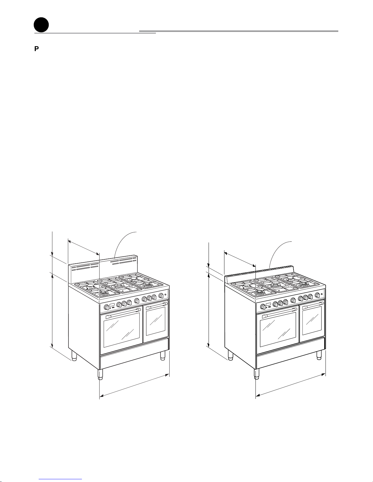
PROXIMITY TO SIDE CABINETS
1. This range may be installed directly adjacent to existing 36"
(914 mm) high base cabinets.
Range dimensions:
• width: 35” 7/8 (911 mm)
• depth: 23” 31/32 (609 mm)
• height (without backguard / island trim): MIN 35” 7/16
(900-mm) MAX 37” 13/32 (950 mm)
• backguard (height): 8” (203 mm)
• island trim (height): 3” (76- mm)
Gas line opening:
Wall - 7”
15/32 (190 mm) from the floor; 15” 3/4 (400 mm) from
the rear right side of the range.
Grounded outlet: the electric cord with 3-prong ground plug
has a length of 72” (1830 mm). Grounded outlet should be
located 20”
1/8 (511 mm) from the left side to centre of range
and from 5”
1/8 (130 mm) to 7” 3/32 (180 mm) [depending on
feet regulation] from the floor.
8"
(203 mm)
23"
31/32
(609 mm)
(911 mm)
35"
7/8
MIN 35" 7/16 (900 mm)
MAX 37"
13/32 (950 mm)
3"
(76 mm)
23"
31/32
(609 mm)
(911 mm)
35"
7/8
MIN 35" 7/16 (900 mm)
MAX 37"
13/32 (950 mm)
Fig. 1.1a
Fig. 1.1b
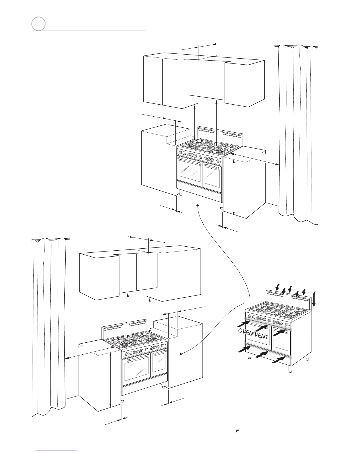
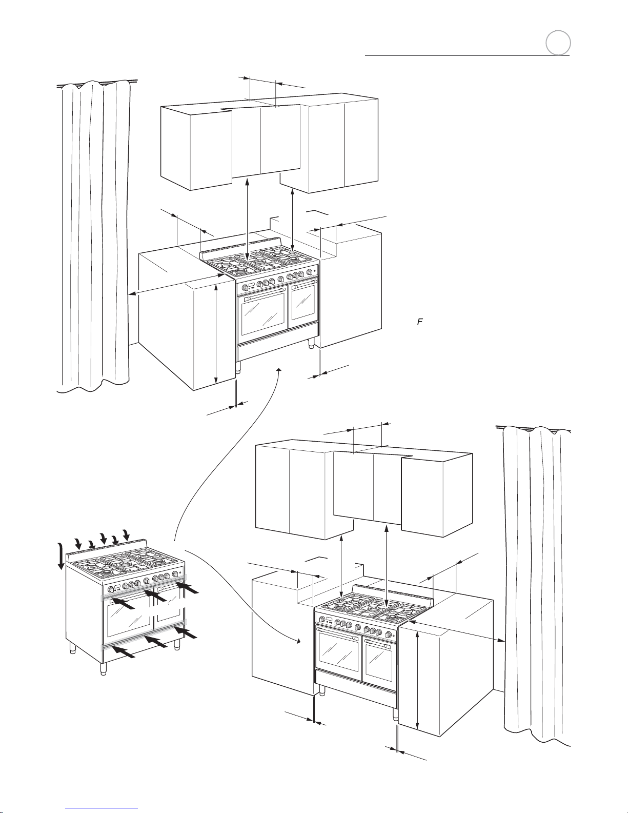
2. The range CANNOT be installed directly adjacent to sidewalls, tall cabinets, tall appliances, or other side vertical
surfaces above 36” (914 mm) high.
There must be a minimum of 11” 13/16 (300 mm) side clear-
ance from the range to such combustible surfaces TO THE
LEFT or TO THE RIGHT above the 36” (914 mm) high countertop.
IMPORTANT: One side (left or right) above the 36” (914
mm) high countertop must always be kept clear.
Installation with island trim: There must be a minimum of 12”
(305 mm) clearance from the back of the island trim to such
combustible surface on the back of the range above the 36”
(914 mm) high countertop.
3. The maximum upper cabinet depth recommended is 13” (330
mm). Wall cabinet above the range must be a minimum of 30”
(762 mm) above the countertop for a width of minimum 35”
7/8 (911 mm): it has to be centred with the range. Side wall
cabinets above the range must be a minimum of 18” (457
mm) above the countertop.
Backguard
Island trim
1
7
A
B
D
C
GAS AND ELECTRIC CONNECTION
Dotted line showing the position
of the range when installed
* : Depending on feet regulation
Area for ELECTRICAL connection
Area for GAS connection
Fig. 1.2
a
Rif. inch mm
A 7” 15/32 190
B 15” 3/4 400
C 5” 1/8 ÷ 7” 3/32
(*)
130 ÷ 180
(*)
D 20” 1/8 511
1
8
(457 mm)
18" min.
30" min.
(762 mm)
(914 mm)
36"
0"
(0 mm)
0"
(0 mm)
20" min. (500 mm)
11"
13/16
min. (300 mm)
13" max. (330 mm)
(457 mm)
18" min.
30" min.
(762 mm)
(914 mm)
36"
0"
0"
(0 mm)
(0 mm)
20" min. (500 mm)
11"
13/16
min. (300 mm)
13" max. (330 mm)
OVEN VENT
OVEN VENT
a
Fig. 1.3b
Fig. 1.3a
PROXIMITY TO SIDE CABINETS
RANGE WITH BACKGUARD
1
9
a
Fig. 1.3c
Fig. 1.3d
PROXIMITY TO SIDE
CABINETS
RANGE WITH ISLAND TRIM
(457 mm)
18" min.
30" min.
(762 mm)
(914 mm)
36"
0"
0"
(0 mm)
(0 mm)
20" min. (500 mm)
13" max. (330 mm)
11"
13/16
min. (300 mm)
12"
min. (305 mm)
(457 mm)
18" min.
30" min.
(762 mm)
(914 mm)
36"
0"
(0 mm)
0"
(0 mm)
20" min. (500 mm)
11"
13/16
min. (300 mm)
13" max. (330 mm)
12"
min. (305 mm)
OVEN VENT
OVEN VENT
OVEN VENT
1
10
10
a
Fig. 1.4
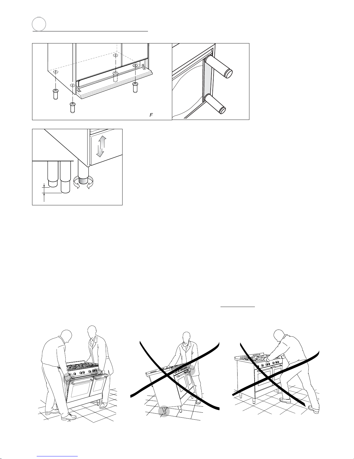
FITTING THE ADJUSTABLE FEET
The adjustable feet must be fitted to the base of the cooker before use.
Rest the rear of the cooker on a piece of the polystyrene packaging exposing the base
for the fitting of the feet.
ATTENTION: Most important! Pay special attention not to damage the range during this operation.
Fit the 4 legs by screwing them tight into the support base as shown in picture 1.5.
Fig. 1.5
LEVELLING THE COOKER
The cooker may be levelled by screwing the lower ends of the feet IN or OUT (fig.
1.6).
+ 1" 31/32
+ 50 mm
0 mm
0"
Fig. 1.6
Fig. 1.7a
Fig. 1.7b
Fig. 1.7c
MOVING THE COOKER
WARNING
When raising cooker to upright position always ensure two people carry out this
manoeuvre to prevent damage to the adjustable feet (fig. 1.7a).
WARNING
Be careful: do not lift the cooker by the door handle when raising to the upright
position (fig. 1.7b).
WARNING
When moving cooker to its final position DO NOT DRAG (fig. 1.7c).
Lift feet clear of floor (fig. 1.7a).
1
11
11
a
A
B
A
B
A
A
B
B
Fig. 1.8
Fig. 1.9
ASSEMBLING THE BACKGUARD
OR THE ISLAND TRIM
It is mandatory to install the
backguard or the island trim
• Assemble the backguard or the island trim as
shown in figure 1.8 or 1.9 and fix it by screwing
the 5 screws “A” (which are already fixed on
the back of the cooktop).
• Do not remove the 3 spacers "B" already fitted
on the back of the backguard or island trim.
1
12
12
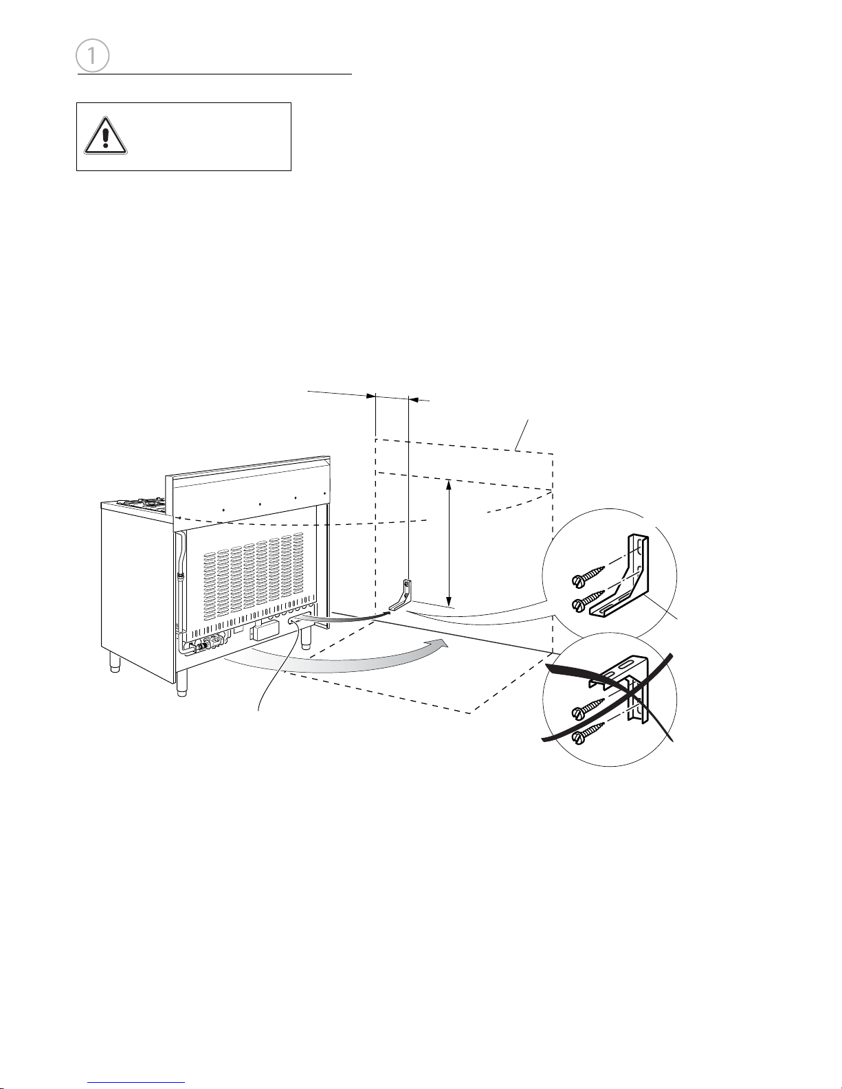
ANTI-TIP STABILITY DEVICE INSTALLATION INSTRUCTIONS
1. The anti-tip bracket has to be attached as shown on figure below, it has to be fixed on
the rear wall by no. 2 (two) suitable screws (supplied with the anti-tip kit).
2. After fixing the anti-tip bracket, slide range into place. Be sure the anti-tip bracket is
fully inserted in the slot of the range back.
28" 15/16 (735 mm)
from top of cooktop
with range installed
in final position
(158.5 mm)
6"
15/64
Dotted line showing the position
of the range when installed
Slot for inserting
the anti-tip bracket
ANTI-TIP STABILITY
DEVICE FIXING
Fig. 1.10
Anti-tip
stability device
YOU MUST USE STABILITY
ANTI TIP BRACKET TO
PREVENT UNIT FROM
TIPPING.
a
1
13
13
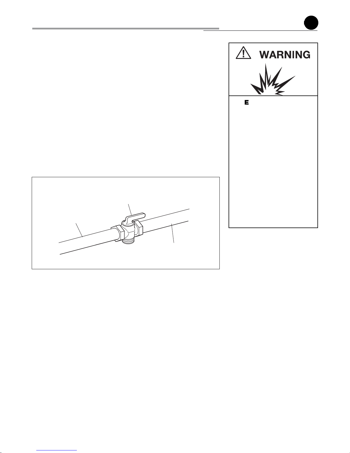
Gas supply line
Shutoff valve
“open” position
To range
Fig. 2.1
All gas connections must be made according to national and local codes. This
gas supply (service) line must be the same size or greater than the inlet line of the
appliance. Sealant on all pipe joints must be resistant to te action of LP/Propane
gas.
The range is equipped for the use with NATURAL gas. It is design-certified by CSA
International for NATURAL and L.P. gases with appropriate conversion.
The model/serial rating plate, located on the inner side of the storage compartment
pivoting panel, has information on the type of gas that can be used. If this information
does not agree with the type of gas available, check with the local gas supplier. See
page from 19 to 23 for L.P. gas conversion inctructions.
1. Manual Shut-off Valve (fig. 2.1):
The supply line shall be equipped with an approved shutoff valve. This valve should
be located in the same room as the range and should be in a location that allows
ease of opening and closing (in a position where it can be reached quickly in the
event of an emergency).
Do not block access to the shutoff valve. The valve is for turning on or shutting off
gas to the appliance.
2. Pressure Regulator:
a) All heavy duty, commercial type cooking equipment must have a pressure regulator
on the incoming service line for safe and efficient operation, since service pressure
may fluctuate with local demand.
Before installing the regulator mount the 1/2” NPT (conical) male connector to the
regulator (see picture 2.2a). Gasket supplied have to be placed between 1/2” NPT
(conical) connector/extension pipe male pipe fitting (see picture 2.2b).
The regulator supplied with this range must be installed before any gas connections
are made.
Use supplied pressure regulator only.
b) Assemble the extension pipe + pressure regulator group to the range manifold
interposing the gasket supplied.
gas connection
B
Explosion Hazard
Use a new CSA or UL approved
gas supply line.
Install a shut-off valve.
Securely tighten all gas connec-
tions.
If connected to LP, have a quali-
fied person make sure gas pressure does not exceed 14" water
column.
Examples of a qualified person
include licensed heating personnel, authorized gas company personnel, and authorized
service personnel.
Failure to do so can result in
death, explosion, or fire.
2
14
14
b
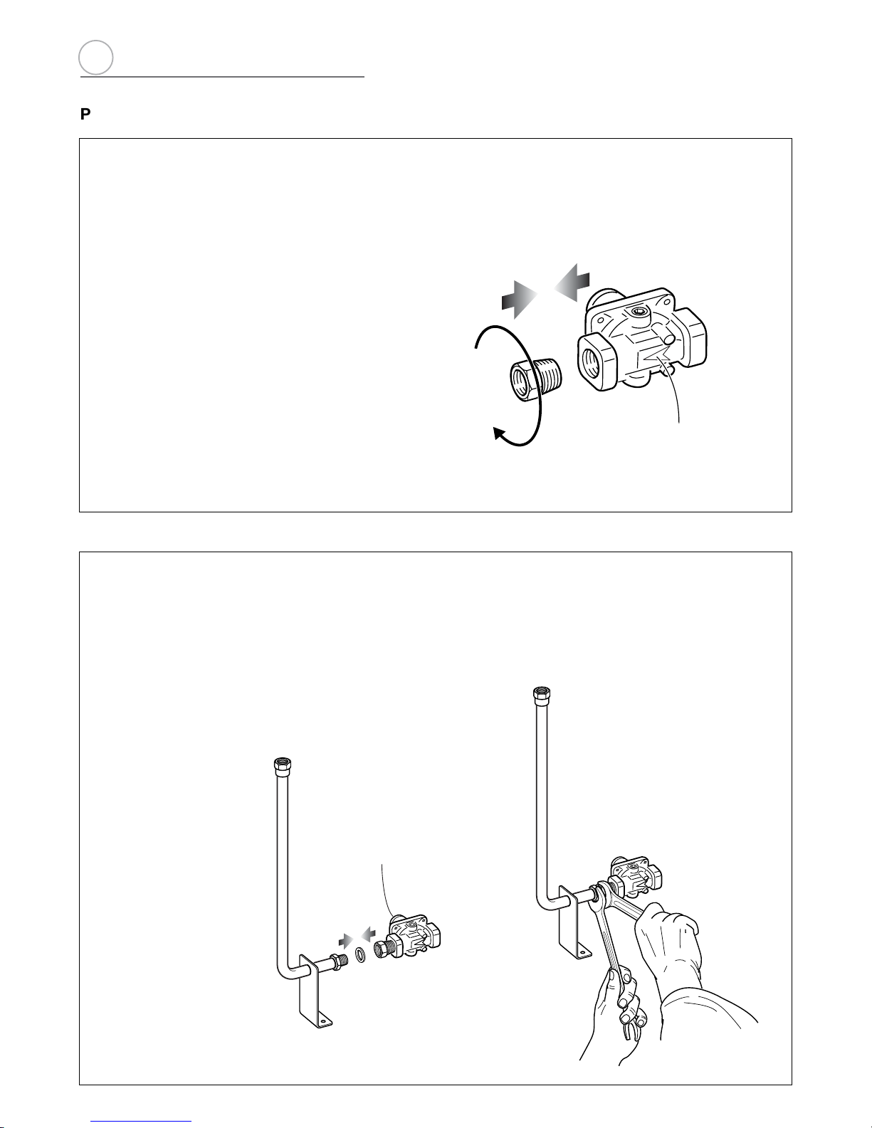
PRESSURE REGULATOR INSTALLATION
LOCK
Arrow
STEP 2
Assemble the 1/2” NPT connector + pressure regulator group to the
extension pipe interposing the gasket supplied. The regulator cover
must be ordiented toward the front side of the range.
IMPORTANT: use two spanners to tighten the connection.
Regulator
cover
Fig. 2.2a
Fig. 2.2b
STEP 1
Mount the 1/2” NPT (conical) male connector to the pressure
regulator and tighten by using a wrench.
Do not over tighten the connector.
Over tightening may crack regulator.
2
15
15
b
A
A
STEP 3
Insert the extension pipe + pressure regulator
group in the “A” bracket.
STEP 4
Assemble the extension pipe + pressure regulator
group to the range manifold interposing the
gasket supplied. The regulator cover must be
ordiented toward the front side of the range.
IMPORTANT: use two spanners to tighten the
connection.
Fig. 2.2c
Fig. 2.2d
2
16
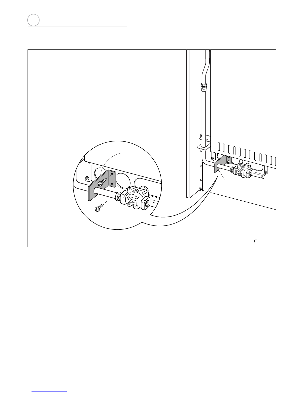
B
B
STEP 5
Fix the “B” bracket on the back of the range
by the 2 (two) screws supplied with the kit for
gas connection.
The regulator cover must be ordiented toward
the front side of the range.
b
Fig. 2.2e
2
 Loading...