

Page 1
SERVICE MANUAL Colour Television
FILE NO.
Model No.PC-R20R2
(USA)
Service Ref.No.PC-R20R2-00
SPECIFICATIONS
Receiving System
Colour System
Picture Tube
Ext. Antenna
Ext. In/Out
Speaker
Audio Output
Power Consumption
Dimension
Net Weight
REMOTE CONTROL
Transmitting System
Power Supply
Dimension
Net Weight
Design and specifications are subject to change without prior notice.
: M
NTSC
:
: 20 inch screen
: 75 Ohm Coaxial Cable
Audio/Video -In/Out
:
: (8 Ohm) x 2
: Maximum 3W
: AC 120V 60Hz, 84W
: 525(W) x 510(D) x 464(H)mm/
20.7(W)
: 22.8 kg/50.26lbs
: Infrared
: DC 3V (1.5 x 2)
: 60(W) x 200(L) x 24(D)mm/
2.4
: 100 g(approx)/0.22lbs
x20.1(D) x 18.3(H)inch
(W) x 7.9(L) x 0.9(D)inch
Product Code: 1 113 495 46
Original Version
Chassis Series: 3Y03
Give complete SERVICE REF.NO. for
parts order or servicing. It is shown on
the rating plate at the cabinet back of
the unit.
This T.V. Receiver will not work properly in
foreign countries where the television
transmission system and power source
differ from the design specifications.
Refer to the Specification table.
""
REFERENCE NO. SM 2300011
Page 2

Contents
Safety Notice..................................................................2
Chassis Block Diagram....................................................3
IC Block Diagram .........................................................4-7
PCB Top Layer .............................................................8-9
Service Adjustments .................................................10-16
Purity and Convergence Adjustment ...............................17
Control Location............................................................18
Input and Output Terminals.............................................19
Operation Instructions...............................................20-21
Mechanical Disassemblies .............................................22
Cabinet Parts List ..........................................................23
Circuit Diagram..............................................................24
Chassis Electrical Parts List.......................................25-33
Safety Notice
SAFETY PRECAUTIONS
1:An isolation transformer should be connected in the power line between the receiver and
the AC line when a service is performed on the primary of the converter transformer of the
set.
2:Comply with all caution and safety-related notes provided on the cabinet back, inside the
cabinet, on the chassis or the picture tube.
3:When replacing a chassis in the cabinet, always be certain that all the protective devices
are installed properly,such as,control knobs, adjustment covers or shields, barriers,isola tion resistor-capacitor networks etc.. Before returning any television to the customer,the
service technician must be sure that it is completely safe to operate without danger of
electrical shock.
X-RADIATION PRECAUTION
The primary source of X-RADIATION in television receiver is the picture tube. The picture
tube is specially constructed to limit X-RADIATION emissions. For continued X-RADIATION
protection, the replacement tube must be the same type as the original including suffix
letter. Excessive high voltage may produce potentially hazardous X-RADIATION. To avoid
such hazards, the high voltage must be maintained within specified limit. Refer to this
service manual, high voltage adjustment for specific high voltage limit. If high voltage exceeds specfied limits, take necessary corrective action. Carefully follow the instructions for
+B1 volt power supply adjustment, and high voltage check to maintain the high voltage
within the specified limits.
PRODUCT SAFETY NOTICE
Product safety should be considered when a component replacement is made in any area
of a receiver. Components indicated by mark in the parts list and the schematic diagram
designate components in which safety can be of special significance. It is particularly
recommended that only parts designated on the parts list in this manual be used for component replacement designated by mark . No deviations fromresistance wattage or voltage ratings may be made for replacement items designated by mark .
-2-
!
!
!
Page 3
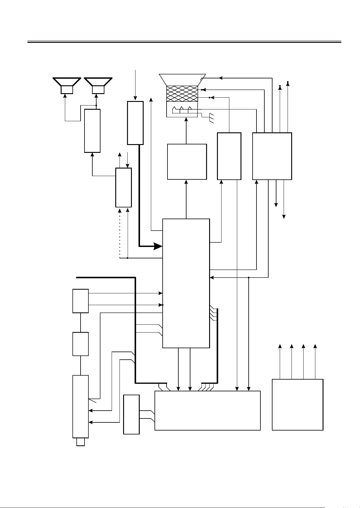
Chassis Block Diagram
SPEAKER-L
SPEAKER-R
AV1/AV2
VIDEO-OUT
CRT
FOUCS
SCREEN
Ic400
IC403
La4285
AV1/AV2 AUDIOIN
HEF4O53BP
La7840
VERTICAL
I c301
RGB AMP
DEFLECTION
HORIZONTAL
FBP
DEFECTION
I c401
HEF4O52BP
V-OUT
40
VIDEO-IN
TV-AUDIO
41
19-21
23
H-OUT
24V
9V/12V
H-FBP
28 27
I c201
SAW.FIL
PRE.AMP
SDA/SCL
RF-AGC
SCL
TUNER
Ic002
SDA
EEPROM
4 5 6 2
11 1 2
40
AFC
VIDEO
29
19
30
LA76814/76810
14-17
110V (B+)
10
R G B Y
V.SYN
H.SYN
22-25
14
21
20
21V5V9V
LC863224A-5V23
27 28
Ic001
POWER
VIDEOIN
-3-
Page 4
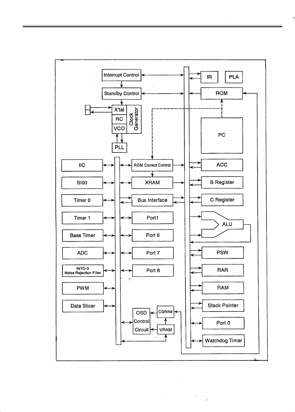
IC Block Diagram
IC 001 (MULTI SYSTEM COLOR TV CPU) LC863224A
-4-
Page 5
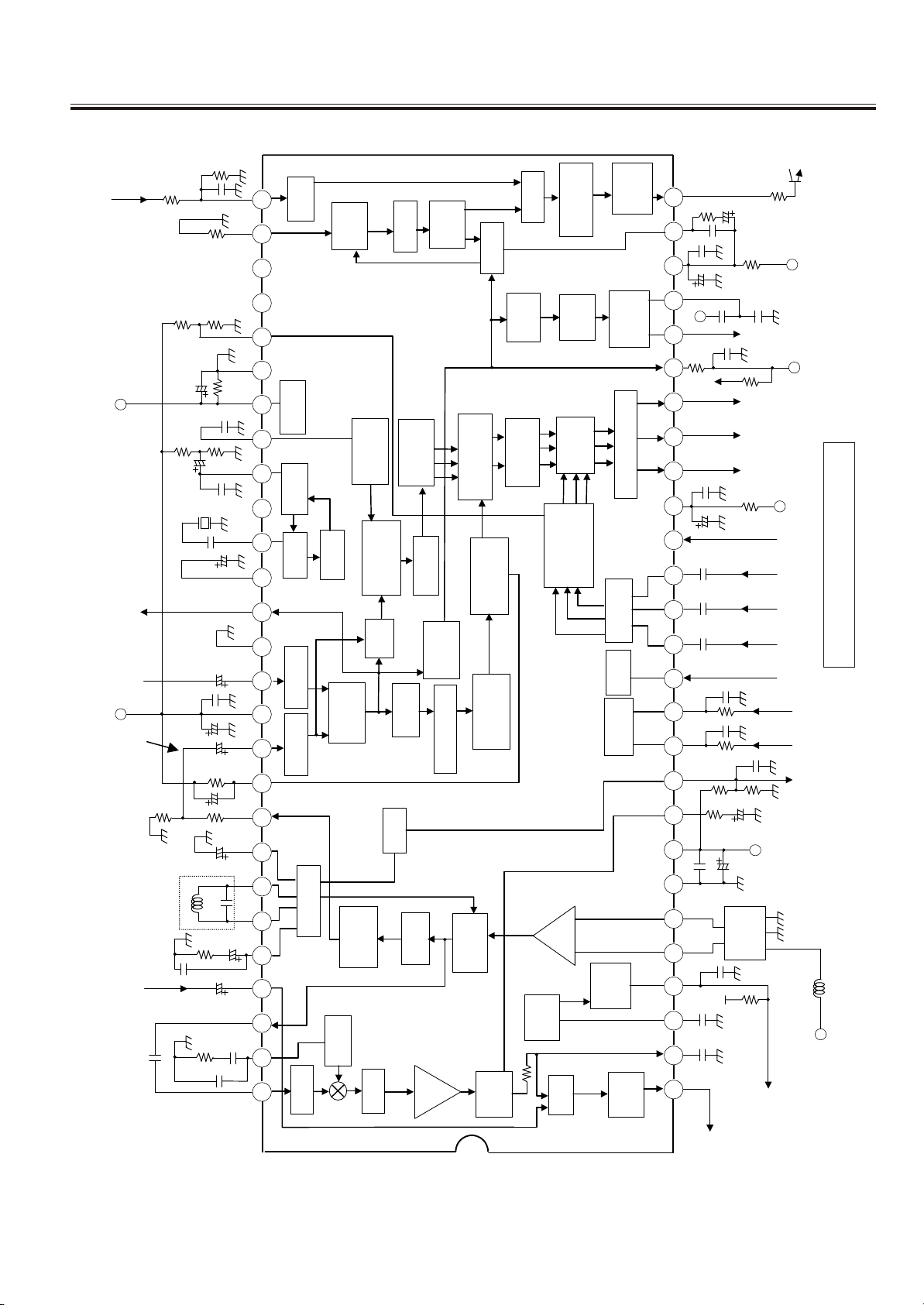
IC Block Diagram
IC 201 (IIC BUS SINGLE CHIP VIF,SIF,VIDEO CHROMA) LA76814K
7.5K
IN
FBP
V/C
VCC
10K
330p
REF
4.7K
MetalFilm(1%)
1K
1K
HOR
GND
10K
1u
1000p
24K
24K
0.47u
0.01u
16p
10u
SVO
V/C
GND
1u
[Y-IN ]
EXT-V IN
EXT-AUDIO
0.01u
47u
[S-C IN]
INT-V IN
15uH
1K
VCO
1000p
IN
10p
1u
680K
330
2.2u
1K
0.47u
COIL
0.47u
330
10u
3K
0.01
1000p
FBP
C/D
VCO
29 28
32 31 30
XRAY
36 35 34 33
APC1
VCO
39 38
40 37
43 42 41
44
CLAMP CLAMP
46 45
48 47
50
52 51 49
53
54
HOR
ACC
KILLER
TINT
BPF
(ON/OFF)
SW
SW
VIDEO
AFT
A2C PLL
AMP
VIDEO
SPLL
BPF
BPF
HOR
1/256
COLOR
CLAMP
DEMO
SYNC
TRAP
TRAP
LIM
AMP
BRIGHT
CONTRAST
BLACK
SEP
PEAKING
DELAYLINE
DET
VIDEO
AFC2
PHASE
AFC1
VER
RGB
STRETCH
CORING
FM
DET
VER
SEP
OSD
MATRIX
OSD
CONTRAST
VIF
IF
AGC
SW
HOR
OUT
SHIFTER
Vcc
HOR
C/D
VER
RAMP
SW
DRIVE/CUTOFF
BRIGHT
CLAMP
ABL
BUS
5V
IF Vcc
RF
AGC
DC
VOL
OUT
HOR
1u
3K
0.01u
10u
56p
100
Vcc
0.01u
10u
0.1u( )
0.1u( )
0.1u( )
1K
1K
10 11 12 13 14 15 16 17 18 19 20 21 22 23 24 25 26 27
100K
0.01u
5 6 7 8 9
0.01u
0.022u( )
0.01u( )
1 2 3 4
VC
AUDIO
0.015u
150
0.33u( ) 0.33u( )
VER
5.6k
B
G
R
100
100
0.1u
100K
1u
100
SAW
FILTER
30K
OUTP
150
OUT
OUT
OUT
OUT
IF
HOR
VCC(9V)
Out
Sync
VCC
(9 12V)
IN
FB
B
IN
G
IN
R
IN
LA76814K BLOCK DIAGRAM
ABL
BUS
CLOCK
BUS
DATA
AF
VCC
IF IN
RF
-5-
Page 6
IC Block Diagram
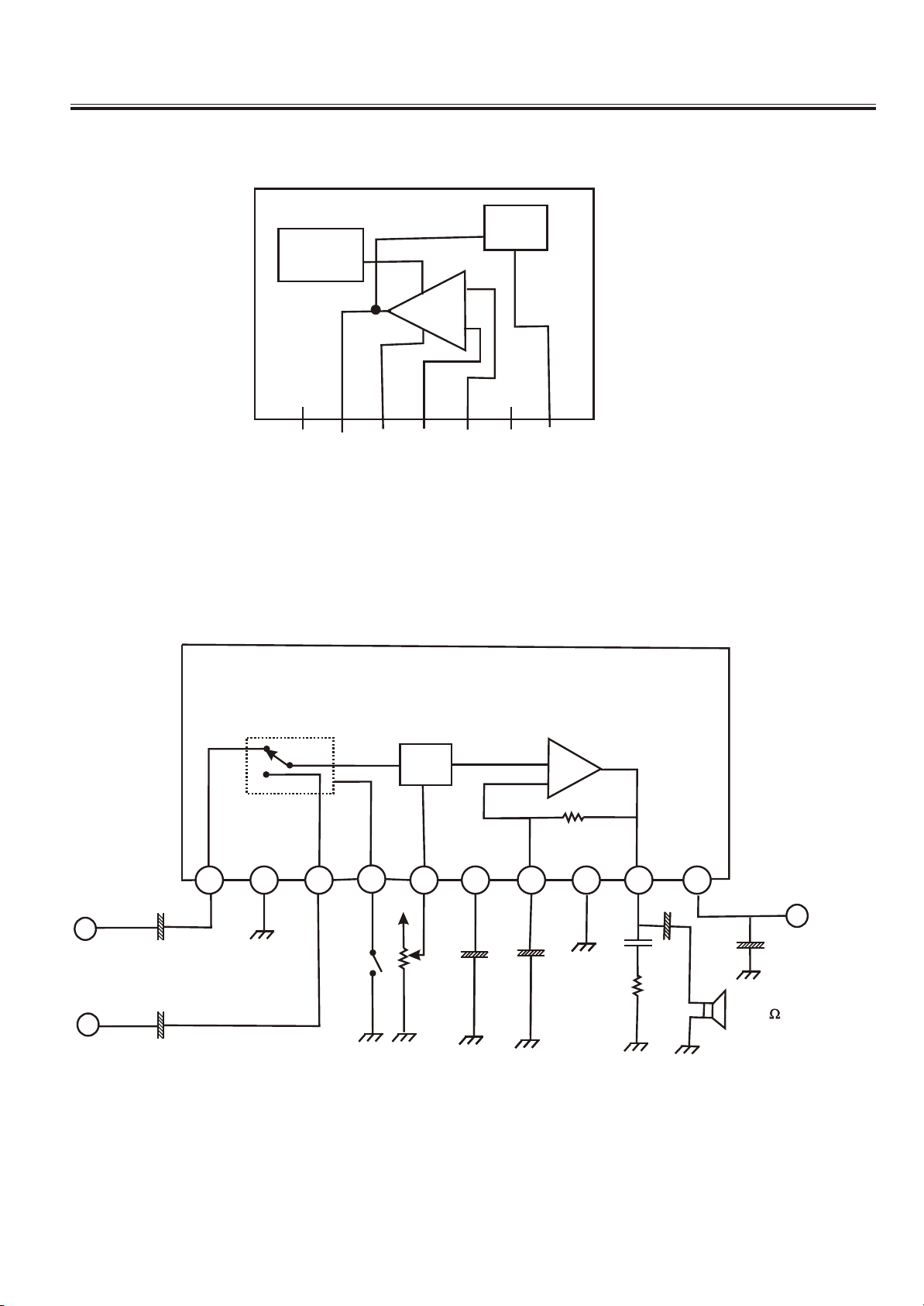
IC301<Vertical Output> LA7840
THERMAL
PROTECTION
PUMP
UP
-
AMP
+
1
2
GND
Ver.OUTPUT
IC 403(3W AUDIO OUTPUT)LA 4285
3
OUTPUT STAGE Vcc
EVR
4
5
NON INV.INPUT
INVERTINO INPUT
7
6
c
c
V
PUMP UP OUT
+
-
INT
EXT
1 2 6543 1097 8
5V
++6++
++++
PRE
GND
INT/EXT
SM
EVR
CONT
-6-
D.C.
PWR
NF
PWR
GND
VCC
++
+
+
RL 8
Page 7
IC Block Diagram
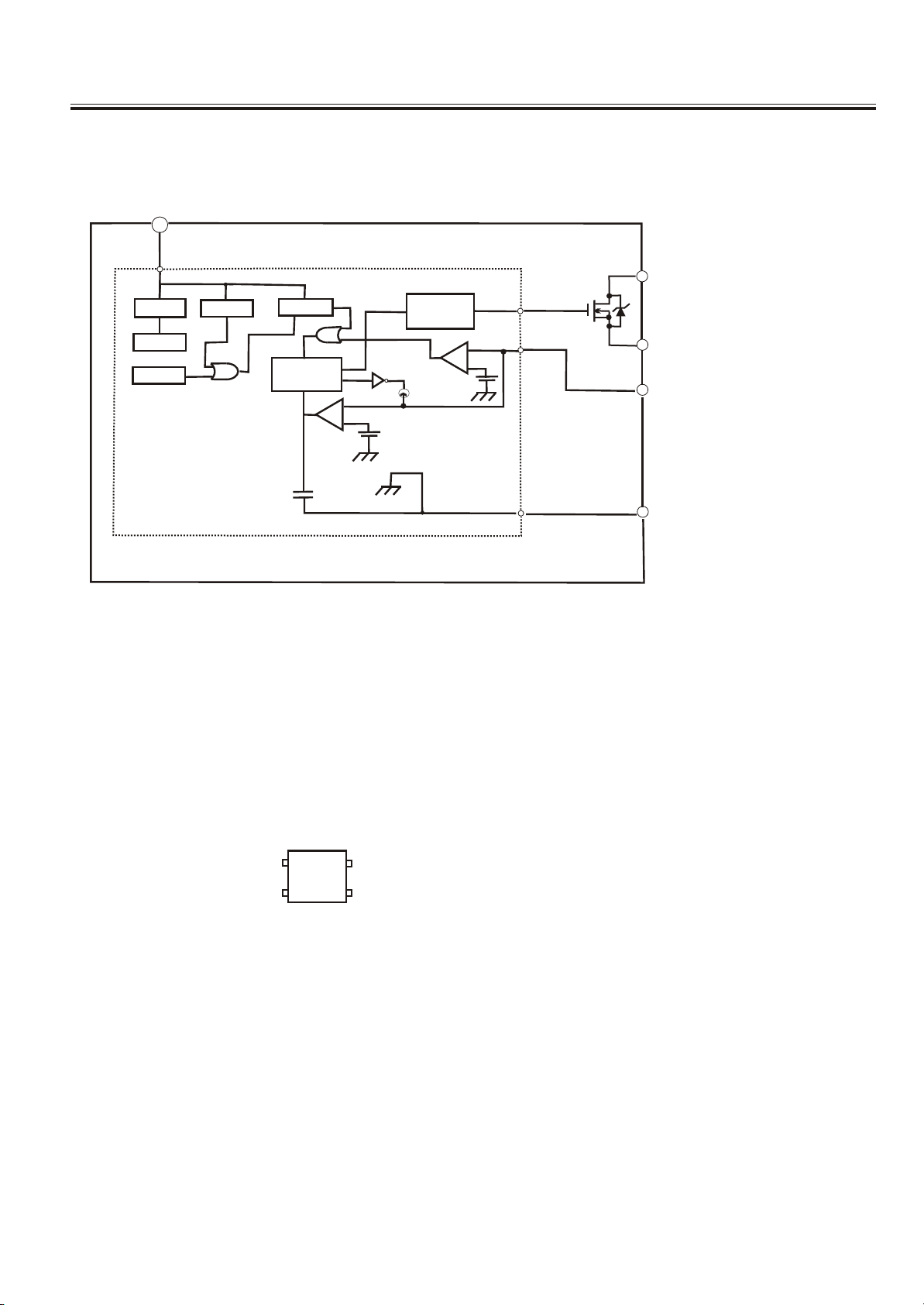
IC602<POWER > STR-G6653
VIN
4
1
D
START
REG.
T.S.D
O.V.P
LATCH
O.S.C
+
Comp2
Comp2
DRIVE
2
-
Vth(1)
+
Comp1
-
Vth(2)
S
5
O.C.P/F.B
3
GND
IC603<PHOTO TRANSISTOR> TLP621
TLP621
1
2
1:ANODE
2:CATHODE
3:EMITTER
4:COLLECTOT
4
3
-7-
Page 8
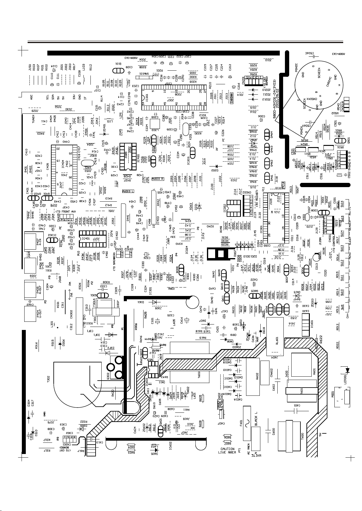
MAIN PCB Top Layer
-8-
Page 9
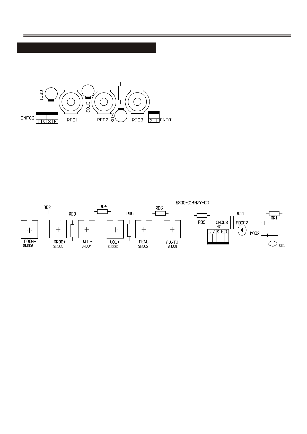
CRT, FRONT AV&CONTROL PCB Top Layer
FRONT AV & CONTROL PCB TOP LAYER
-9-
Page 10
Service Adjustments
Please notice the following before alignment and equipment
1. Don’t short any two soldering points, which should not be shorted and don’t touch any components,
which should not be touched.
2. Please pull out plug before equipment.
3. For safety reasons, all components equipped or replaced should be identical with BOM.
4. Must be warm up for 30 minutes or more and degauss CRT thoroughly with demagnetizer before
alignment.
The data of EEPROM must be stored before the adjustment for main chassis. And EEPROM must be
corrected by the correct file “3Y03_ROM_CORRECT.hex” to avoid signal of CH6 weaken. R.bias,
G.bias, B.bias, R.drv, G.drv, B.drv should be set to proper values. Sub_bright is set to 63 usually.
Tools and equipments for adjustment
1. small “-“ screwdriver
2. screwdriver without inductance
3. Pattern Generator
4. DC Regulated power supply
5. Digital Voltmeter
6. Sweep Signal Generator
7. 20MHz 2-channel Oscilloscope
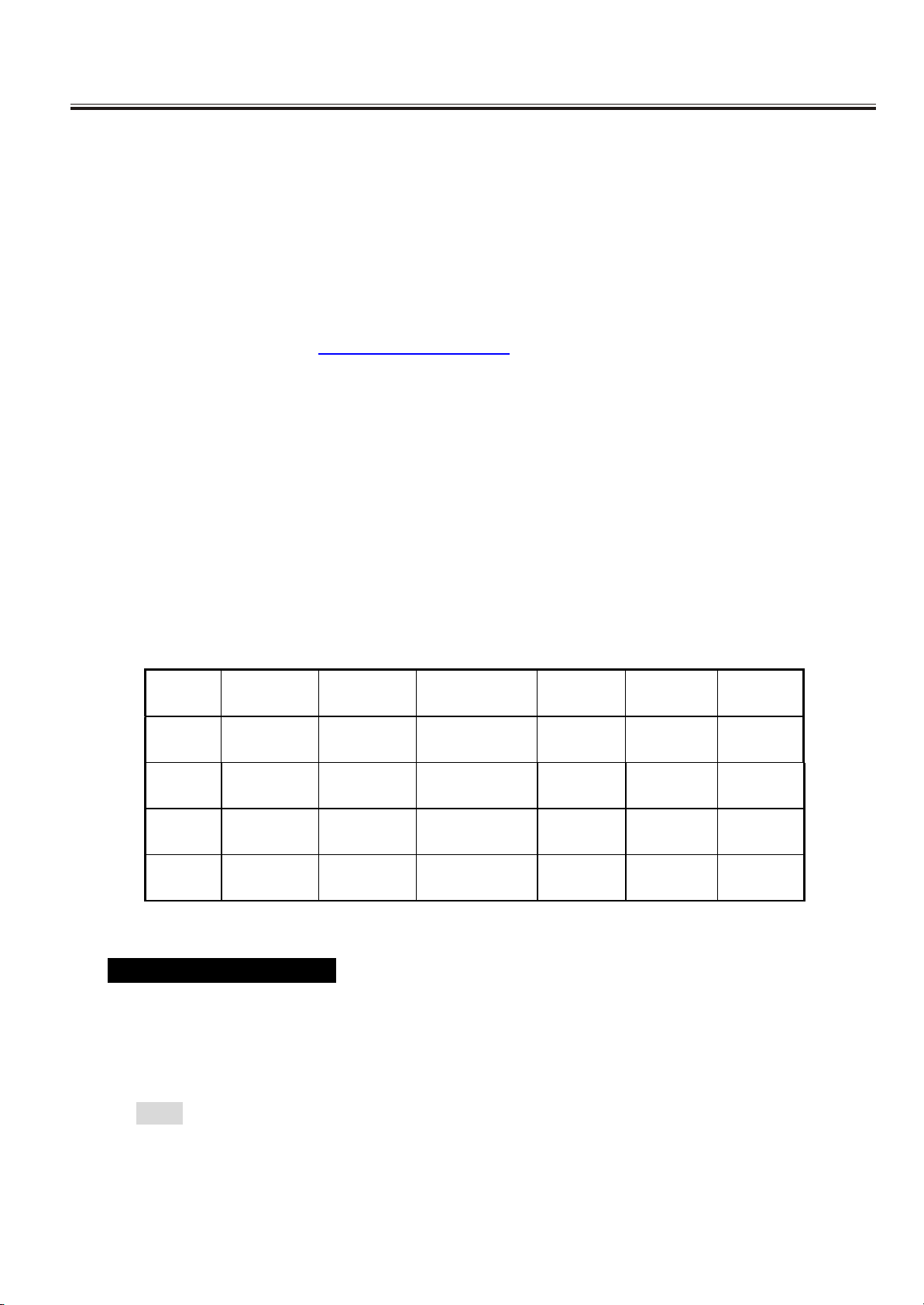
Signal condition
ITEMS LOGO
PICTURE
CARRIER
PATTER N SYSTEM
SOUND
MODE
REMARK
1 CH14 471.25 MHZ COLOR BAR NTSC/M
MONO
1KHz
2 CH3 61.25 MHz GRAY SCALE NTSC/M
BTSC
0.3k,3kHz
3 CH8 181.25 MHz MONOSCOPE NTSC/M
MONO
MUSIC
4 CH12 205.25 MHz
CROSS HATCH
NTSC/M
MONO
1KHz
Adjust for main chassis
PIF Adjustment (45.75MHz)
a. Tuner AGC connects to GND. Pattern Generator outputs 45.75MHz I.F. signal (70dbµV)and connects to SAW filter
output terminal through a capacitor .
b. Connect Digital voltmeter across C227. DC Regulated power supply positive terminal output +14V to C617.
c. Adjust L203 coil to obtain 3.6V Digital voltage meter reading.
NOTE: To cancel this adjustment , L203 can be adjusted before inserted to the chassis with a special equipment.
-10-
Page 11

Service Adjustments
B+ adjustment
a. Disconnect horizontal load. Connect a bulb (100 W) AC 250V across C321.
b. Add 220V AC 50HZ to CN601 and switch on power switch.
c. Test the voltage with digital voltage meter between C321 two terminals.
d. Adjust VR601 to obtain +110V¡À0.5V.
AGC alignment
a. Receive 60dB RF signal. Connect Digital voltmeter positive terminal to tuner AGC terminal and negative terminal
to GND.
b. Press “MENU” key, then press “Q.VIEW” key, “MUTE” key in turn on telecontroller. TV SET will go to factory mode.
Press “TIMER” key to go to the next factory menu. Go to MENU5 status by this means. Press “MENU” key to exit
factory mode.
c. Select RF.AGC by pressing “CH+” and “CH-“keys. Adjust “VOL+” and “VOL-“ keys to obtain 4V Digital voltage
meter reading.
COMPLETE MACHINE GENERAL ADJUSTMENT
Go to factory mode according to 4-2-2 before warm up line
Focus Adjustment
a. Receive monoscope pattern.
b. Set TV to work in dynamic status.
c. Adjust the focus knob of FBT to get the clearest picture.
Screen Voltage Adjustment
a. Check the R.bias, G.bias, B.bias, R.drv, G.drv, B.drv and sub_bright. Go to factory mode “MENU2” status
according to 4-2-2. Usually G.bias should be same as the value of auto white balance equipment. And
SUB_BRIGHT is 63.
b. Set Cross_BW ‘3”. Then the picture will be a white “+”. Cross_BW is in factory menu 3.
c. In menu 5, select SUBB.ADJ and set it to “1”. Adjust the screen knob of FBT to get a faintness “+”.
d. Restore the SUBB.ADJ to “0” and CROSS.BW to “0”.
White Balance Adjustment (Applied in factory)
a. Set TV AV status in custom mode(Or other mode need for the adjustment) . Receive black white pattern.
b. Insert six-row-wire into CN002.Press adjustment keys, and then go to automatic white balance adjustment.
c. PIN DISCRIPTIONN OF CN002:
1£ºSDA£¬ 2£ºSCL£¬ 3£ºGND£¬ 4£ºGND£¬ 5£ºSCL£¬ 6£ºSDA¡£
d. After adjusting well, pull out six-row-wire.
-11-
Page 12

Ver tical size and pincushion adjustment
White balance adjustment (Applied when servicing)
a. Set TV AV status and receive GREY SCAL.
b. The one sampling tube of CRT color analyzer (CA-100) covers on GREY signal and
the another covers on white signal.
c. Go to factory mode “MENU2”. Obtain GREY signal X=281 and y=311 by adjusting R-CUT and B-cut. Obtain white
signal X=281 and y=311 by adjusting R-DRV and B-DRV. Obtain both X=281 and Y=311 by adjusting the two
status repeatedly.
Sub_bright adjustment
Receive the gray scale . Get into the menu5 of factory mode. Set SUBB.ADJ to “1”. Then adjust the SUB..BRI
option to get a scale to be seen a little brightness(Only two rows can be seen).
Vertical Size and PinCushion Adjustment
a. Receive monoscope pattern. Set TV standard status. Adjust V.size to obtain picture’s vertical redisplay ratio more
than 90% in factory mode “MENU1”.
b. Receive cross hatch pattern. Set TV standard status. Adjust V.LINE and V.SC to obtain picture’s vertical pin
cushion a good status in factory mode “MENU1”.
c. Receive cross hatch pattern. Set TV standard status. In factory mode “MENU1” adjust V.POS to obtain picture’s
vertical center at the center of CRT screen.
Horizontal Center Adjustment and horizontal position of OSD adjustment
a. Receive monoscope PATTERN. Set TV standard status. Adjust H.PHASE in menu 1 to obtain horizontal center
at the center of CRT screen.
b. Adjust the “OSD.HPOS” to get right display position.
SUB.TINT ADJUSTMENT
Receive the color bar signal of NTSC system. Set the picture mode at normal mode. Adjust the ‘SUB.TINT’ option
in menu5 at sevice mode to get the right hue .
MTS ADJUSTMENT
Receive the RF CROSS-TALK signals , but FM with BTSC .Enter into the factory mode. Set ADJ.FREQ to 1 in
“9852 AUTO.ADJ”. Wait 1 second . Quit factory menu after “ADJUSTING ” change to “0” .
Service Adjustments
-12-
Page 13

COLOR PURITY ADJUSTMENT
a. Before color purity adjustment, Warm up the TV set over 15 minutes and fully degauss.
b. Receive pure white signal in AV status and set the TV receiver dynamic.
c. Go to factory mode “MENU2”. After write down the values of R-BIAS and B-BIAS, set the values of R-BIAS and
B-BIAS zero.
d. Loosen the clamp screw of the deflection yoke and pull the deflection yoke towards color purity magnetic loop.
e. Adjust color purity magnetic loop to make the green area at the center of CRT screen.
f. Slowly push the deflection yoke toward the front of CRT and set it where a uniform green field is obtained.
Tighten the clamp screw of the deflection yoke.
g. Restore the values of R-BIAS, G-BIAS and B-BIAS.
CONVERGENCE ADJUSTMENT
a. Receive a dotted pattern. Set the TV receiver dynamic.
b. Loose the convergence magnet clamper and align red with blue dots at the center of the screen by rotating (R, B)
static convergence magnets.
c. Align Red/Blue with green dots at the center of the screen by rotating (RB-G) static convergence magnet.
d. Remove the DY wedges and slightly tilt the deflection yoke horizontally and vertically to obtain the good overall
convergence. Fix them after the good overall convergence got.
e. Fix the convergence magnets by turning the clamper.
f. If purity error is found, follow “PURITY ADJUSTMENT” instructions.
Purity Magnet
RB-G RB
Magnet Clamper
Static Magnet
Ver tical size and pincushion adjustment
Service Adjustments
-13-
Page 14

Ver tical size and pincushion adjustment
APPENDIX
FACTORY MENU DISCRIPTION
MENU1 VAL UE DISCRIPTION
1 V.SIZE 101 Align vertical amplitude
2 V.POS 32 Align vertical DC bias
3 V.LINE 16 Align vertical linearity
4 V.S C 0 Align vertical S-correction
5 H.PHASE 8 Align sync to flyback phase
6 H.BLK.RL 4 H-blanking Control(Width /Phase)
7 H.FREQ 22 Align ES Sample horizontal frequency
MENU2
1 V.KILL 0 Disable vertical output
2 R.B 138 Align Red out DC level
3 G.B 182 Align Green out DC level
4 B.B 148 Align Blue out DC level
5 R.D 67 Align Red out AC level
6 G.D 8 Align Green out AC level
7 B.D 45 Align Blue out AC level
MENU3
1 RG.GAM 1 Disable R/G gamma correction (0/ON; 1/OFF)
2 B.GAM 3 Select and Disable B gamma correction(0~2/ON;3/OFF)
3 R.B.ANG 1 Adjust the demodulation angle of R-Y and B-Y
4 AT.FLESH 0
5 GRAY.MODE 0 Select Test mode (0/White; 1/Gray)
6 CROSS.BW 0 Service Test mode (0/TV; 1/Black; 2/White; 3/Crosshatch)
7 AFC.GAIN 0 Select Horiz. 1st loop gain & H-sync gate on/off(0/auto;1/enforce)
8 H.BLK.SW 0 H BLK R&L selection(0/right side blanking can be adjusted;1/left)
MENU4
1 FILT.SYS 1 Select Y/C filter mode(0,2/3.58 unsymm.; 1,3/3.58 sym.; 4~7/no filt)
2 CORING 1 Enable Luminance coring( 0/Off; 1/ON)
3 OSD.CONT 1
4 OSD.HPOS 30 Align the horizontal position of OSD
5 BLK.STR.D 0 Disable black stretch
6 BRIABL.T 0 Align brightness ABL threshold
MENU5
1 RF.AGC 31 Align RF AGC threshold
Service Adjustments
-14-
Page 15

Service Adjustments
OPTION
1 2 AV.CH 3 Select AV numbers(0/ No AV;1/1 AV; 2,3/2AV)
2 SRH.SPEED 0 Select auto search speed(0/fastest, 7/lowest)
3 TDA9852 1 Disable 9852(0/disable; 1/able)
4 TUN.AS.V 1 Select the Tuner address(0/Tuner pin3 to ground;1/pin3 not used)
9852 AUTO.ADJ
1 ADJ.FREQ 0 Disable auto adjusting(0/disable; 1/get into autoadjust mode)
2 ADJUSTING 0
3 FM.LVL 16
4 76075.VOL 0
5 L3-L0 0 input level adjust
6 TC2-TC0 0 timing current alignment data
7 A14-A10 0 stereo alignment data for wideband expander
8 A24-A20 0 stereo alignment data for spectral expander
TDA1
1 VOL.RIGHT 125 volume control right
2 VOL.LEFT 125 volume control left
3 GMU 0 mute control for all outputs (general mute )
4 AVLON 0
auto volume control (with 0.1Vrms-1.1Vrms input to get constant output
0.2Vrms)
5 LOFF 0 switch loudness on/off
6 CCD 0
7 SC2-SC0 2 selection between line in and line out
8 SAP.ID 0
TDA2
1 STERO.ID 1
2 TZCM 0 zero cross mode in volume operation
3 LMU 0 mute control for line out
4 EF2-EF0 0 selection between mono, stereo linear, spatial stereo and pseudo mode
5 L3-L0 0 input level adjust
6 A14-A10 0 stereo alignment data for wideband expander
7 A24-A20 0 stereo alignment data for spectral expander
8 STS 0 stereo level switch
Ver tical size and pincushion adjustment
-15-
Page 16

White Balance address
White Balance address
Data Name E2PROM Address
LA76814 ADDRESS
#1011 1010B
bright 12H #0001 0100B
contrast 11H #0001 0101B
color 10H #1011 1010B
Sub-bright 24H #0001 0011B
R.B 1EH #0000 1101B
G.B 1FH #0000 1110B
B.B 20H #0000 1111B
R.D 21H #0001 0000B
G.D 22H #0001 0000B
B.D 23H #0001 0010B
TDA3
1 ADJ 0 stereo adjust on/off
2 AT1 -AT2 0 attack time at AVL
3 TC2-TC0 0 timing current alignment data
4 WR.ERR 0
5 RD ERR 0
6 MANU ADJ 0
7 STEREO 0 mode selection for line out
8 SAP 0 mode selection for line out
Service Adjustments
Ver tical size and pincushion adjustment
-16-
Page 17

Purity Magnet
RB-G RB
Magnet Clamper
Static Magnet
Purity and Convergence Adjustment
COLOR PURITY ADJUSTMENT
(1) Before color purity adjustment,warm up the TV set over 15 minutes and fully degauss.
(2) Receive pure white signal in AV status and set the TV receiver dynamic.
(3) Go to factory mod MENU2. After write down the values of R-BIAS and B-BIAS, set the values of R BIAS and B-BIAS zero.
(4) Loosen the clamp screw of the deflection yoke and pull the deflection yoke towards color purity
Magnetic loop.
(5) Adjust color purity magnetic loop to make the green area at the center of CRT screen.
(6) Slowly push the deflection yoke toward the front of CRT and set it where a uniform green field is
Obtained. Tighten the clamp screw of the deflection yoke.
(7) Restore the values of R-BIAS,G-BIAS AND B-BIAS.
CONVERGENCE ADJUSTMENT
(1) Receive a dotted pattern. Set the TV receiver dynamic.
(2) Loose the convergence magnet clamperrrrr and align red with blu dots at the center of the screen by
rotating(R,B) static convergence magnets.
(3) Align Red/Blue with green dots at the center of the screen by rotating(RB-G) static convergence
magnet.
(4) Remove the DY wedges and slightly tilt the deflection yoke horizontally and vertically to obtain the
good
-17-
Page 18

Control Location
1. Remote Sensor
2. Power Indicator
3. Main Switch
4. Speakers
5. Program Down & Up Button
6. Volume Down & Up Button
7. Menu Button
8. AV/TV Button
9. Front AV In (Option)
10. Audio/Video - In/Out Jack
11. AC Power Cord
12. Terminal Antenna (75 Ohm)
(STEREO)
5 86 74 9 4
2
3
1
(MONO)
11
10
12
-18-
Page 19

Input and Output Terminals
VIDEO AND AUDIO INPUT/OUTPUT TERMINALS
1. Video / Audio input for playback for VCR.
2. Video / Audio output for TV monitor output.
*Please keep AC cord unplugged when connecting TV system.
(STEREO)
AV-OUT
VIDEOVIDEO AUDIOAUDIO
R
(MONO)
OUT IN
VIDEO VIDEOAUDIO AUDIO
AV-IN
LL
R
NOTE:
This is a mono CTV even though there are R & L audio input & output jack. These
audio R/L input terminals are parallel connected inside and make mixed monaural
sound output .There are same monaural audio output come from R/L output terminals.
-19-
Page 20

Operation Instructions
Turn the TV set on, then power indicator will light up. After a few seconds , the currently program number is
displayed on the top right -hand corner of the screen.
MENU BUTTON
1.Press this button to select menu. VIDEO, TIME, and SETUP menu can be selected cyclically.
Video Menu Time Menu Setup Menu
Audio Menu
(Option)
Exit Menu
2.After enters each menu, you can select the desired adjusting item by the PROG.+/- buttons, and adjust the
item by the VOL. +/- buttons.
*When you select a item, symbols¡° / ¡± will display both sides of the item.
Video menu
1.Enter the video menu , you can select the picture quality instantly among four
Video
Audio
Time
Setup
Custom
Contrast
Bright
Sharpness
Color
Tint
-15
16
16
16
16
preset modes and one user-set mode.
(User-set mode)
Custom Standard Sports Movies Mild
*You can adjust CONTRAST ,BRIGHT , SHARPNESS , COLOR and TINT items
by pressing the VOL. +/- buttons . The adjusted level is stored in Custom mode.
Audio menu(option)
Video
Audio
Time
ST
SAP
Balance
Mono
On
00
1.ST:
Press the VOL.+/-buttons can select the stereo mode , the order shown below:
Mono Spatial Linear Psuedo
Setup
Time menu
Video
Audio
Time
Setup
Clock
Timer
TV On
TV Off
--:-Off
--:--
--:--
2.SAP:
You can adjust the SAP ON to SAP OFF by the VOL+/-buttons ,.
You can use the Second Audio Program when you select the SAP ON .
3.BALANCE:
Press the VOL+/-buttons can adjust the left or right volume balance .
* The MTS/SAP function is only an option for some models.
1.CLOCK:
Press the VOL.- button to set hour, and the VOL.+ button set minute .
2.TIMER£º
When you select the "Timer ON" mode, you can set the time of TV ON or TV
OFF.
*TV On: The TV will automatically turn on at the preset time.
TV Off: The TV will automatically turn off at the preset time.
-20-
Page 21

Operation Instructions
Setup menu
1.After enters the setup menu, you press the PROG+/-buttons to select
Video
Audio
Preset
Captain
Time
V-Chip
Setup
Language
PRESET MENU , CCD MENU AND V-CHIP MENU
PRESET MENU
Preset
System
Channel
Skip
Auto Search
Fine Tune
Antenna
03
Off
PRESET MENU, CCD MENU and V-CHIP MENU.
2.Select the Language item by the PROG+/-buttons, and press the VOL.+/buttons to select the desired language . The screen menu is automatically
displayed in that language.
The order shown below:
English Espanol Portugues
1.SYSTEM
you can switch two signals :CABLE and ANTENNA .
2. CHANNEL
Select the cable signal ,there are 01~125 channels
Select the antenna signal , there are 02~69 channels .
3.SKIP
Select "Skip ON" by VOL.+/- Buttons to skip unnecessary program
number.
4.AUTO SEARCH
Press VOL.+/-buttons to start auto searching.
5.FINE TUNE
In areas of inferior broadcast conditions where adjustment is necessary for
CCD MENU
Closed
Caption
Caption
Mode
Channel
Field
V-CHIP MENU
V-Chip
Input Pwd
V-Chip
V-Chip On
MPAA
TVPG
Content-V
Content-S
Content-L
Content-D
Off
Capt.
PG
TV-14
1.CAPTION
Set the caption OFF or ON .
2.MODE
1
1
Select the caption mode or teletext mode .
3.CHANNEL
Select channel 1 or channel 2 .
4.FIELD
Select field 1 or field 2 .
Input the password¡° 9999 ¡±to call up V-Chip, MPAA and TVPG item.
1.V-CHIP
Set the V-Chip OFF or ON .
2.MPAA movie rating
B
B
B
B
Select the type of program
3.TVPG(TV Parental Guidelines)
Parents can guide their children watching some programmes by the item.
-21-
Page 22

Mechanical Disassemblies
CABINET BACK REMOVAL
1. Refer to Figure 1,remove 9 screws.
2. Pull off cabinet back and remove.
CHASSIS REMOVAL
1. Remove cabinet back.
2. Discharge the picture tube anode(2nd anode lead) to the
dag coating (picture tube grounding lead).
3. Disconnect Degaussing coil socket(KE),Picture tube socket,
Deflection yoke connector (KDY), Speaker connectors(KL
and KR), and 2nd anode lead.
4. Remove chassis completely by sliding it straight back.
PICTURE TUBE REMOVAL
CAUTION: Do not disturb the deflection yoke
or magnet assembly on the picture tube
Neck. Care must be taken to keep these
assemblies intact, unless picture tube is
being replaced. Discharge the picture tube
to the coating before handing the Tube.
1. Remove chassis, referring to Chassis Removal instructions.
2. Place cabinet front face down on the soft surface.
3. Remove the screw on each corner of the picture tube and
GENTLY lift the picture tube out of the cabinet.
4. Install a replacement picture tube in reverse order.
Properly install the degaussing coil and picture tube
grounding lead on the picture tube. See Figure 2.
DEGAUSSING
COIL
Note: If the Picture Tube is being replaced, mount the
Degaussing Coil on the picture tube. See following..
DEGAUSSING
COIL HOLDER
PICTURE TUBE
GROUNDING LEAD
DEGAUSSING
COIL SOCKET
To CRT Unit
ground
-22-
Page 23

Cabinet Parts List
1
5
6
3
4
2
1
7
10
8
9
Key No. Part Number Description
1 SKCM 0021NZM110 CABINET COLOUR MATCH-METAL SILVER GREY #MSG001(3Y07)(3Y03) FOR SANYO
2 SK100721NZM 002 FRONT LENS (REMOTE CONTROL WINDOW)
3 SK100721NZM 002 FRONT LENS (LED WINDOW)
4 Sk190100821210 POWER KNOB SPRING - DIA.0.6SPRING WIRE
5 SK100425TM 0002 SIDE AV JACK BRACKET-DARK GREY #DG001(ABS)
6 SK100821NZM 001 CONTROL KEY KNOB-ELECTROPLATING SILVER(ABS)
7 SK060121NZM 001 BACK LABEL "SKYWORTH" OVERSEAS ENG
8 SK100221NX0001 BACK CABINET-DARK GREY #DG001
9 SK1016HS080003 BATTERY DOOR-NORMAL GREY #NG001(ABS)
10 SKHS08S0300000 HANDSET-30 KEYS FOR OVERSEAS NORMAL GREY ENG(3Y03)
-23-
,, ,,
,, ,,
Page 24

5V(1)
(OPTION)
FRONT AV
AC110V
VOL
POWER
PROG-
SW008
RD2
56K
5V(1)
AFT
R032
1.5K
ZD003
3.6V
AV V OUT
IC201 PIN40
V OUT
AR OUT
AL OUT
V IN 1
AR IN 1
AL IN 1
!
F601
T3.15A/AC250
!
LN
PROG+
SW007
RD3
22K
CN601
!
M001
PMA64xxM
VOL-
SW006
R033
8.2K
10U/50V
T601
AR IN
9V(2)
C205
100U/16V
C620
Q609
9V(2)
9V(1)
AR-OUT
R409
2.2K
C426
R410
0.0082UF
20K
C427
0.015UF
AUDIO R
AUDIO L
FM
0.022U
C207
5V(2)
C016
0.1U
R200 470
R209 470
C237 100P
C240 10U/25V
C222 0.01U
C212
470U/16V
SAW101
45B
R008
100K
2.2U/50V
C236 100P
C239 0.22U
R255 100
R254 100
R256 100
C217 0.1U
C219
0.33U
R210
3K3
C216
1U/50V
C206
0.01U
R007
100K
R208 47
47U/16V
R211
120
C214
0.01U
POWER
B+
IC004
33V
33V
C424 0.015UF
C423 0.015UF
C425 2.2U/50V
42
40
39
41
38
VIR
EOR
LDR
Cps237Cps1
OUTR
OUTL1LDL2VIL3EOL4CAV5Vref6LIL7AVL8SOL9LOL10CTW11CTS12CW13CS14VEO15VEI16CNR17Cm18Cdec19GND20SDA
2.2U/50V
C402
C404
C401
C406 100U/16V
C403 4.7U/50V
0.1U/M
0.0082UF
R402
20K
R401
2.2K
C243
0.047U/M
C203
C221
0.022U
R201
20K
C215
LA76814
1
A OUT
2
FM OUT
3
PIF AGC
4
RF AGC
5
IF IN
6
IF IN
7
IF GND
8
IF VCC
9
FM FIL
10
AFT OUT
11
BUS DATA
12
BUS CLOCK
13
ABL
14
R IN
15
G IN
16
B IN
17
FB IN
18
VCC
19
R OUT
20
G OUT
21
B OUT
22
SYNC
23
V OUT
24
RAMP ALC
25
H VCC
26
H AFC FIL
H OUT27FBP IN
V-SYNC
C315
1U/50V
C316
0.033U/M
IC201
R340
5.1K
V-IN
C422 2.2U/50V
36
LIR
47U/16V
C405
BLACK S.F
VCC V/C/D
KILLER FIL
C450
0.022U
35
AVR
C450
0.022U
AL-OUT
SIF IN
SIF FIL
SIF OUT
EXT.A IN
APC FIL
FLL FIL
TV OUT
INT.V IN
EXT.V IN
G V/C/B
V OUT
ACC FIL
XRAL
FSC OUT
APC1 FIL
XRAY
H GND
OSD CON
VCO IREF
R301
47K
C325
100/16V
D301
BA158
C304
220U/50V
R407
2.2K
C419
X401
2.2U/50V
503F58
C421 4.7U/50V
C420 4.7U/50V
31
34
32
Css
LOR33SOR
10U/16V
10U/16V
1U/50V
C408
C407
C409
AL IN
C245
39PF
54
53
52
51
C241
39PF
50
49
VCO
48
VCO
C209
47
0.47U
46
R225 1K R229 1K
45
C230
44
1U/50V
43
42
41
1U/50V
40
39
C235
38
15P
37
C238
5n6
0.01U
36
35
C228
34
1000P
33
32
31
NC
R213
1K5
30
NC
29
28
R212
R241
4.7K
10K
IC301
LA7840
7
R319
15K
R329
10K
R320
1.2 2W
20V
5V(1)
C630
0.01U
IC203
L7805
5V(2)
B+
9V(1)
R630
R644
100K/2W
10K
Q301
2SC2482
R307
100
R114
R110
47
BLK
IC201 PIN42
100U/160V
C640
1000U/25V
C621
0.01U/50V
R653
ZD601
3V9
R109
270
2SC2717
C321
C618
470U/25V
Q101
AFT
OSD-R
OSD-G
OSD-B
BLK
V-IN
R629
10K
R646
3K9
C642
0.01U
R621
L102
0.82UH
CN201
R625
15K 2W
0
Q611
2SA966
2KB(H)
220
C109
0.01U
5V(2)
5V(1)
9V(2)
ABL
IC601
L7805
10U/50V
R626
0
R628
22
R632
10K
78L09
Q610
2SC1815
VR601
NC
SCL
ADD
RFAGC
R103
123456789
120K
C104
4.7U/50V
R107
33K
R101 100
L101
100UH
5V(2)
R002
5V(1)
C001 0.01U
1K
13
Q003
2SA1015
C009
330U/16V
C012
2.2U/50V
R719
AR OUT
12
ACOM
R435
100
!
C607
1
2
5
3
4.7K
R065
OCP/FB
R043
10K
R437
R438
R436
R439
1000P
C010 0.01U
AI311AI0
R431
10K
R434
10K
220U/200V
C614
R022
22K
R021
C007
R037 10K
R036 10K
Q008
2SC1815
9V(2)
10K
10K
10K
10K
10
8
R605
2M2
R608
2M2
15P
C008
15P
CONA9CONB
4K7
R001 10K
33K
C004
220P
C005
100P
32.768K
C014
4.7U/50V
R465
10K
R464
10K
IC401
HEF4052
L602
R610
680
R603
0.22/1W
D605
4148
R013
4.7K
X001
Q007
2SC1815
1
2
3
4
5
6
7
8
9
10
11
12
13
14
15
16
17
18
19
20
21
Q462
2SC1815
C608
0.001U/2KV
R604
0.22/1W
WRITE
IDsecam
IDscart
VOL
COB.F
POWER
TUNE
GND
XTF1
XTF2
VDD
KEY
AFT
PGCin
OPT
RESET
FIL
OPTselect
Vsyn
Hsyn
D201
1N4148
AV/TV SW
Q601
2SC2482
LA8633XX
V-SYNC
Q461
2SC1815
L601
D609
IN4148
IC001
AV1/2 SW
R612 10K
ZD602
15V
D604
IN4148
R643
1K
R613
47/0.5W
BA158
C610
100UF/35V
BALANCE
H-SYNC
AL-OUT
4.7UF/160V
D611
3
CR1
0.022U
2
RD11
1
LED
RR1
1K
1
5V(1)
SLEEP
VOL+
MENU
SEARCH
AV/TV
R067
24K
SW002
SW004
SW005
SW003
10U/50V
R602
SCK473
!
SW
C436
R445
10K
C601A
.0047
C601D
.0047
R601
PTC
RD7
4.3K
5V(2)
AR-OUT
10
9V(2)
Q401
2SC1815
9V(2)
C011
0.01U
R038
47U/16V
D601D
39K/3W
SW001
RD8
RD9
3K
2K
RD21 15K
RD21
16K
CN001 PIN3
5V(1)
R039
100
C013
0.022U
1M
5V(1)
Q221
J147
2SC1815
1K
R226
2.2K
AL-OUT
R440
100
C432
47U/16V
C431
47U/16V
15
16
VDD
BI01BCOM3BI34BI15INHBIT6VEE7GND
BI2
2
C434
47U/16V
C433
R433
R432
10K
10K
9V(2)
1N5397 X4
D601A
D601C
!
D601B
R607
STR-G6653
4
!
BLOCK
CONTROL
IC602
AR-IN
AI114AI2
RD5
RD4
RD6
6.8K
11K
4.7K
Q006
2SA1015
R034
4.7K
9V(2)
VOUT
Q402
2SC1815
C435
R446
10K
!
C602
.22/250V
!
R622
!
2M7
!
CN602
L601
DEG.COIL
!
R102 100
S_VHS
M_TRAP
REMOTE
SAFTY
IICCLK
IICDATA
0.1U/63V
SDA
MUTE
DATA
V_L
V_H
UHF
AV2
AV1
SD
CLK
BLK
AL-IN
9V(2)
C623
R609
47
R611
C611
B
G
R
2K2
VCC
C111
0.01U
C110
330U/16V
R463
10K
VCC
R462
10K
BA158
NC
33V
42
41
40
39
38
37
36
35
34
33
32
31
30
29
28
27
26
25
24
23
22
D610
680P/500V
0.0033/100V
IC603
5V(1)
T601
D602
IN4148
C609
33V
10
5V(1)
R051 100
R052 100
C605
0.0022U/250V
IF1
IF2
11
C108
1U/50V
R050 9K1
R049 4.7K
D010 1N4148
D009 1N4148
D008 1N4148
D007 1N4148
R240
100K
1
!
3 7
4
5
6
!
C613
TUNER
C107
0.01U
R048 4.7K
R7125K1
R4F1
75
0.68/2W
!
C114
R108
0.01U
5.6K
R105
0
R111
1K
AV1/2 SW
AV/TV SW
R047 4.7K
R046 4.7K
IC002
24C04
R031
330
OSD-B
R030
330
OSD-G
R029
330
R7115K1
R710
5K1
OSD-R
R7091K
AV VOUT
C615
680P/500V
C616
100U/160V
R618
D607
BYW36
C641
680P/500V
9
D640
BA158
R619
2.2 /2W
10
11
D608
C617
BA158
2200U/25V
12
C619
680P/500V
BA158
R642
C612
1.2K
0.1U
R645
1K
Q602
2SC1815
10U/16V
C439
Cadj29CER30Cmo
R403
1U/50V
R404
C410
150
C411
0.047UF
L203
45.75M
C232
3.579545M
C227
R214
1K
C328
100U/16V
R308
2.7K 1/2W
0.0022U/1KV
28
X201
!
9V(2)
C309
C417 0.47U/M
8.2K
10U/16V
R327
2.2 2W
C324
0.47U
R318
C323
1U/50V
R324
3.9K
C414 10U/16V
C233
1122334455667
100K
25V
C322
560P/500V
C418
0.22U/M
C416
25
Cp126Cp227Cph
C413 0.1U/C
R243
1K
L241
15UH
R303
5.1K
C326
2200U/25V
220U/16V
100U/16V
24
Vcap
C412 4.7U/50V
C242
0.001U
C231
0.1U
R221
10K
9V(2)
C320
0.056U/250V
9V(2)
COMP
C246
0.01U
R222
22K
5V(2)
R330
1.5K
R306
5.1K 5W
C310
C441
100P
23
Vcc
C224
0.001U
T301
R408
12/1W
220U/16V
22
21
R233
390
5V(2)
R309
1K 1W
C415
SCL
C440
100P
123
!
C442
0.01U
IC404TDA9852
R405
100
D221 IN4148
180 1W
IC302
LA7809
C301
47U/50V
150K 1/2W
R310
22 1/2W
R406
100
C247
0.47U/50V
AV V IN
AV V OUT
R311
R620
ZD401
8V2
SCL
SDA
.0047/2KV
3.9/2W
R316
C313
Q302
2SD2499
!
AUDIO L
VOL
CPU PIN5
AUDIO R
CN301B
FROM CN301
CN201B
FROM CN201
C327
0.1U
C317
680P/500V
D304
BA158
C318
680P/500V
D310
BA158
C314
.0076/2KV
IC402
LA4285
INT1GND2EXT3SW4VOL566NF7GND8OUT9VCC
Q503
D505
1N4148
C506
470u/16V
D504
2SC2482
C448
100U/25V
C445
100U/25V
IC403
LA4285
R508
2K2
R441
R442
R237
560K
R412
4.7K
C437
10UF/50V
9V(2)
R468
15K
Q464
2SC1815
R466
4.7K
D401
R467
W1 W2 W3
1 BO
2 GO
3 RO
4 GND
5 +9V(2)
1.8K
3 HEATER
2 GND
1 +180V
10u/25V
4
1
10U/50V
C438
10UF/50V
C507
C505
0.01U
R326
270 2W
T603 FBT
4148
C453
R523
R530
150K/1W
R503
150
10K
R413
4.7K
15K/2W
R502
150
Q508
2SC1815
INT1GND2EXT3SW4VOL566NF7GND8OUT9VCC
R514
R506
390
C503
150P
R524
270
BA158
!
!
1K
1U/50V
100
1U/50V
C446
C451
R235
5K1
C452
1000UF/25V
R513
15K/2W
R505
390
R501
150
10
10
20V
C502
150P
D306
BA157
R315
22K 1W
R317
0.68 2W
C444
220/25V
C447
220/25V
R511
2K7 1/2W
R510
2K7 1/2W
Q502
2SC2482
D506
R507
1N4148
2K2
CRT PCB
C312
1U/250V
C311
0.47U 250V
15K/2W
R515
390
SPEAKER
8R 3W
SPEAKER
8R 3W
CRT
V501
EHT
R512
R509
2K7 1/2W
Q501
2SC2482
C504
1000P/2KV
C501
150P
D507
R504
1N4148
2K2
CN302
!
R331
44UH
1K5/1W
L301
CN301
3
2
1
!
!
2
TITLE:
SYSTEM:
P/N:
DATE:
FOCUS
SCREEN
3Y03 DIAGRAM
NTSC M
2001-09-27
R322
0.68 2W
7
3
8
R207
10
6
D305
BA158
C302
C303
10U/250V
680P/500V
C308
0.056U/M
R236
1K
680
5V(2)
Page 25

Chassis Electrical Parts List
location quantity description
SK013YA3Y03203M MAIN¡¡ASSEMBLY
&C308 SK4500141481T0 NORMAL RECTIFIER DIODE 1N4148 150mA/100V
&D221 SK4300BE476ET0 ELECTROLYTIC CAPACITOR 47uF 35V +/-20%
&D602 SK4500141481T0 NORMAL RECTIFIER DIODE 1N4148 150mA/100V
&J123 SK4500400056T0 ZENER DIODE 5V6 1/2W
C001 SK4300AF103HT0 CERAMIC CAPACITOR 0.01uF 50V +80-20%
C004 SK4300AF221CT0 CERAMIC CAPACITOR 220PF 50V +/-5%
C005 SK4300AF101CT0 CERAMIC CAPACITOR 100PF 50V +/-5%
C007 SK4300NF150CT0 NPO CERAMIC CAPACITOR 15PF 50V +/-5%
C008 SK4300NF150CT0 NPO CERAMIC CAPACITOR 15PF 50V +/-5%
C009 SK4300BC337ET0 ELECTROLYTIC CAPACITOR 330uF 16V +/-20%
C010 SK4300AF104HT0 CERAMIC CAPACITOR 0.1uF 50V +80-20%
C011 SK4300AF103HT0 CERAMIC CAPACITOR 0.01uF 50V +80-20%
C012 SK4300AF223HT0 CERAMIC CAPACITOR 0.022uF 50V +80-20%
C013 SK4300BF225ET0 ELECTROLYTIC CAPACITOR 2.2uF 50V +/-20%
C014 SK4300BF105ET0 ELECTROLYTIC CAPACITOR 1uF 50V +/-20%
C016 SK4300EF104DT0 METALLIZED POLYESTER FILM CAPACITOR 0.1UF 63-100V +/-10%
C101 SK4300BC476ET0 ELECTROLYTIC CAPACITOR 47uF 16V +/-20%
C104 SK4300BF475ET0 ELECTROLYTIC CAPACITOR 4.7uF 50V-100V +/-20%
C107 SK4300AF103HT0 CERAMIC CAPACITOR 0.01uF 50V +80-20%
C108 SK4300BF105ET0 ELECTROLYTIC CAPACITOR 1uF 50V +/-20%
C109 SK4300AF103HT0 CERAMIC CAPACITOR 0.01uF 50V +80-20%
C110 SK4300BC337ET0 ELECTROLYTIC CAPACITOR 330uF 16V +/-20%
C111 SK4300AF103HT0 CERAMIC CAPACITOR 0.01uF 50V +80-20%
C114 SK4300AF103HT0 CERAMIC CAPACITOR 0.01uF 50V +80-20%
C203 SK4300MG223DT0 MYLAR CAPACITOR 0.022uF 100V +/-10%
C205 SK4300BC107ET0 ELECTROLYTIC CAPACITOR 100uF 16V +/-20%
C206 SK4300AF103HT0 CERAMIC CAPACITOR 0.01uF 50V +80-20%
C207 SK4300BC476ET0 ELECTROLYTIC CAPACITOR 47uF 16V +/-20%
C209 SK4300EF474DT0 METALLIZED POLYESTER FILM CAPACITOR 0.47UF 63-100V +/-10%
C212 SK4300BC477ET0 ELECTROLYTIC CAPACITOR 470uF 16V +/-20%
C214 SK4300AF103HT0 CERAMIC CAPACITOR 0.01uF 50V +80-20%
C215 SK4300MG223DT0 MYLAR CAPACITOR 0.022uF 100V +/-10%
C216 SK4300BF105ET0 ELECTROLYTIC CAPACITOR 1uF 50V +/-20%
C217 SK4300EF104DT0 METALLIZED POLYESTER FILM CAPACITOR 0.1UF 63-100V +/-10%
C219 SK4300EF334DT0 METALLIZED POLYESTER FILM CAPACITOR 0.33uF 63-100V +/-10%
C221 SK4300BF225ET0 ELECTROLYTIC CAPACITOR 2.2uF 50V +/-20%
C222 SK4300AF103HT0 CERAMIC CAPACITOR 0.01uF 50V +80-20%
C224 SK4300MG102DT0 MYLAR CAPACITOR 0.001uF 100V +/-10%
C225 SK4300BF474ET0 ELECTROLYTIC CAPACITOR 0.47uF 50V-100V +/-20%
C227 SK4300AF103HT0 CERAMIC CAPACITOR 0.01uF 50V +80-20%
C228 SK4300MG102DT0 MYLAR CAPACITOR 0.001uF 100V +/-10%
C230 SK4300BF105ET0 ELECTROLYTIC CAPACITOR 1uF 50V +/-20%
C231 SK4300AF104HT0 CERAMIC CAPACITOR 0.1uF 50V +80-20%
C232 SK4300LF105ET0 NONPOLAR ELECTROLYTIC CAPACITO R 1UF 50V+/-20%
C233 SK4300BC106ET0 ELECTROLYTIC CAPACITOR 10UF 16V +/-20%
C234 SK4300BC476ET0 ELECTROLYTIC CAPACITOR 47uF 16V +/-20%
C235 SK4300NF150CT0 NPO CERAMIC CAPACITOR 15PF 50V +/-5%
C236 SK4300AF101CT0 CERAMIC CAPACITOR 100PF 50V +/-5%
C237 SK4300AF101CT0 CERAMIC CAPACITOR 100PF 50V +/-5%
-25-
Page 26

location quantity description
C238 SK4300MG562DT0 MYLAR CAPACITOR 0.0056uF 100V +/-10%
C239 SK4300EF224DT0 METALLIZED POLYESTER FILM CAPACITOR 0.22UF 63-100V +/-10%
C240 SK4300BD106ET0 ELECTROLYTIC CAPACITOR 10uF 25V +/-20%
C241 SK4300NF390CT0 NPO CERAMIC CAPACITOR 39PF 50V +/-5%
C242 SK4300MG102DT0 MYLAR CAPACITOR 0.001uF 100V +/-10%
C245 SK4300NF390CT0 NPO CERAMIC CAPACITOR 39PF 50V +/-5%
C246 SK4300MG103DT0 MYLAR CAPACITOR 0.01UF 100V +/-10%
C247 SK4300BF474ET0 ELECTROLYTIC CAPACITOR 0.47uF 50V-100V +/-20%
C250 SK4300AF103HT0 CERAMIC CAPACITOR 0.01uF 50V +80-20%
C301 SK4300BF476ET0 ELECTROLYTIC CAPACITOR 47uF 50V +/-20%
C302 SK4300AM681DT0 CERAMIC CAPACITOR 680PF 500V +/-10%
C303 SK4300BJ106EC0 ELECTROLYTIC CAPACITOR 10uF 250V +/-20%(FORMED, PITCH=5mm)
C304 SK4300BF227ET0 ELECTROLYTIC CAPACITOR 220uF 50V +/-20%
C306 SK4300BE477E00 ELECTROLYTIC CAPACITOR 470UF 35V +/-20%
C308 SK4300EJ563C01 METALLIZED POLYESTER FILM CAPACITOR 0.056uF 250V +/-5%
C309 SK4300AR222DT0 CERAMIC CAPACITOR 0.0022uF 1KV +/-10%
C310 SK4300EJ563C01 METALLIZED POLYESTER FILM CAPACITOR 0.056uF 250V +/-5%
C312 SK4300BJ475EC0 ELECTROLYTIC CAPACITOR 4.7UF 2 50V +/-20%(FORMED,PITCH=5mm)
C315 SK4300BF105ET0 ELECTROLYTIC CAPACITOR 1uF 50V +/-20%
C316 SK4300MG333DT0 MYLAR CAPACITOR 0.033uF 100V +/-10%
C317 SK4300AM681DT0 CERAMIC CAPACITOR 680PF 500V +/-10%
C318 SK4300AM681DT0 CERAMIC CAPACITOR 680PF 500V +/-10%
C320 SK4300BC227ET0 ELECTROLYTIC CAPACITOR 220uF 16V +/-20%
C321 SK4300BH107EC1 ELECTROLYTIC CAPACITOR 100uF 160V +/-20%(FORMED, PITCH=7.5mm)
C322 SK4300AM561DT0 CERAMIC CAPACITOR 560PF 500V +/-10%
C323 SK4300BF105ET0 ELECTROLYTIC CAPACITOR 1uF 50V +/-20%
C324 SK4300EF474DT0 METALLIZED POLYESTER FILM CAPACITOR 0.47UF 63-100V +/-10%
C325 SK4300BE107ET0 ELECTROLYTIC CAPACITOR 100uF 35V +/-20%
C326 SK4300BD228E00 ELECTROLYTIC CAPACITOR 2200uF 25V +/-20%(16 X 25mm)
C328 SK4300BC107ET0 ELECTROLYTIC CAPACITOR 100uF 16V +/-20%
C430 SK4300BC476ET0 ELECTROLYTIC CAPACITOR 47uF 16V +/-20%
C431 SK4300BC476ET0 ELECTROLYTIC CAPACITOR 47uF 16V +/-20%
C435 SK4300BF106ET0 ELECTROLYTIC CAPACITOR 10uF 50V-63V +/-20%
C438 SK4300BF106ET0 ELECTROLYTIC CAPACITOR 10uF 50V-63V +/-20%
C447 SK4300BD227E00 ELECTROLYTIC CAPACITOR 220uF 25V +/-20%
C448 SK4300BD107ET0 ELECTROLYTIC CAPACITOR 100uF 25V +/-20%
C451 SK4300BF105ET0 ELECTROLYTIC CAPACITOR 1uF 50V +/-20%
C452 SK4300BD108E00 ELECTROLYTIC CAPACITOR 1000uF 25V +/-20%
C453 SK4300BF106ET0 ELECTROLYTIC CAPACITOR 10uF 50V-63V +/-20%
C455 SK4300MG103DT0 MYLAR CAPACITOR 0.01UF 100V +/-10%
C465 SK4300EF104DT0 METALLIZED POLYESTER FILM CAPACITOR 0.1UF 63-100V +/-10%
C601A SK4300AM472DT0 CERAMIC CAPACITOR 0.0047uF 500V +/-10%
C601D SK4300AM472DT0 CERAMIC CAPACITOR 0.0047uF 500V +/-10%
C602 SK4300FW224D00 AC CAPACITOR 0.22uF AC250V-500V +/-10%
C605 SK4300AM681DT0 CERAMIC CAPACITOR 680PF 500V +/-10%
C607 SK4300BI227EC1 ELECTROLYTIC CAPACITOR 220uF 200V +/-20%(FORMED, PITCH=7.5mm)
C608 SK4300ET102C00 METALLIZED POLYPROPYLENE FILM CAPACITOR0.001uF 2KV +/-5%
C609 SK4300MG152DT0 MYLAR CAPACITOR 0.0015UF 100V +/-10%
C610 SK4300BE107ET0 ELECTROLYTIC CAPACITOR 100uF 35V +/-20%
C611 SK4300EF104DT0 METALLIZED POLYESTER FILM CAPACITOR 0.1UF 63-100V +/-10%
C612 SK4300AF104HT0 CERAMIC CAPACITOR 0.1uF 50V +80-20%
C613 SK4300SX222E00 SAFETY CERAMIC CAPACITOR 0.0022uF AC250V-400V +/-20%
C614 SK4300AF471CT0 CERAMIC CAPACITOR 470PF 50V +/-5%
C615 SK4300AM681DC1 CERAMIC CAPACITOR 680PF 500V +/-10% (FORMED,PITCH=7.5mm)
-26-
Page 27

location quantity description
C616 SK4300BH107EC1 ELECTROLYTIC CAPACITOR 100uF 160V +/-20%(FORMED, PITCH=7.5mm)
C617 SK4300BD108E00 ELECTROLYTIC CAPACITOR 1000uF 25V +/-20%
C618 SK4300BD477E00 ELECTROLYTIC CAPACITOR 470uF 25V +/-20%
C619 SK4300AM681DT0 CERAMIC CAPACITOR 680PF 500V +/-10%
C620 SK4300BF106ET0 ELECTROLYTIC CAPACITOR 10uF 50V-63V +/-20%
C621 SK4300AF103HT0 CERAMIC CAPACITOR 0.01uF 50V +80-20%
C623 SK4300BH475ET0 ELECTROLYTIC CAPACITOR 4.7uF 160V +/-20%
C630 SK4300AF103HT0 CERAMIC CAPACITOR 0.01uF 50V +80-20%
C640 SK4300BD108E00 ELECTROLYTIC CAPACITOR 1000uF 25V +/-20%
C641 SK4300AM681DT0 CERAMIC CAPACITOR 680PF 500V +/-10%
C642 SK4300AF103HT0 CERAMIC CAPACITOR 0.01uF 50V +80-20%
CN002 SK540092500006 WAFER 2.5mm H X 6 PIN
CN302 SK540095000005 WAFER 5MM TV-50P-05-V1 5 PIN
CN402 SK540092500002 WAFER 2.5mm H X 2 PIN
CN405 SK540092500003 WAFER 2.5mm H X 3 PIN
CN601 SK540091000002 WAFER 10mm 2.35mm TJC1-2A 2 PIN
CN602 SK540091000002 WAFER 10mm 2.35mm TJC1-2A 2 PIN
D007 SK4100AD5110T0 CARBON FILM RESISTOR 510 OHM 1/4W +/-5%
D008 SK4100AD5110T0 CARBON FILM RESISTOR 510 OHM 1/4W +/-5%
D009 SK4100AD5110T0 CARBON FILM RESISTOR 510 OHM 1/4W +/-5%
D010 SK4100AD5110T0 CARBON FILM RESISTOR 510 OHM 1/4W +/-5%
D221 SK4500215800T0 HIGH SPEED RECTIFIER DIODE BA158 600V/1A
D301 SK4500215800T0 HIGH SPEED RECTIFIER DIODE BA158 600V/1A
D304 SK4500215800T0 HIGH SPEED RECTIFIER DIODE BA158 600V/1A
D305 SK4500215800T0 HIGH SPEED RECTIFIER DIODE BA158 600V/1A
D306 SK4500215800T0 HIGH SPEED RECTIFIER DIODE BA158 600V/1A
D310 SK4500215800T0 HIGH SPEED RECTIFIER DIODE BA158 600V/1A
D401 SK4500141481T0 NORMAL RECTIFIER DIODE 1N4148 150mA/100V
D601A SK450015397000 NORMAL RECTIFIER DIODE 1N5397 1.5A/600V(DO-15)
D601B SK450015397000 NORMAL RECTIFIER DIODE 1N5397 1.5A/600V(DO-15)
D601C SK450015397000 NORMAL RECTIFIER DIODE 1N5397 1.5A/600V(DO-15)
D601D SK450015397000 NORMAL RECTIFIER DIODE 1N5397 1.5A/600V(DO-15)
D602 SK4500141481T0 NORMAL RECTIFIER DIODE 1N4148 150mA/100V
D604 SK4500141481T0 NORMAL RECTIFIER DIODE 1N4148 150mA/100V
D605 SK4500141481T0 NORMAL RECTIFIER DIODE 1N4148 150mA/100V
D607 SK45052BYW3600 HIGH SPEED RECTIFIER DIODE BYW36 2A/600V TELEFUNKEN
D608 SK4500215800T0 HIGH SPEED RECTIFIER DIODE BA158 600V/1A
D609 SK4500141481T0 NORMAL RECTIFIER DIODE 1N4148 150mA/100V
D610 SK4500215800T0 HIGH SPEED RECTIFIER DIODE BA158 600V/1A
D611 SK4500215800T0 HIGH SPEED RECTIFIER DIODE BA158 600V/1A
D640 SK4500215800T0 HIGH SPEED RECTIFIER DIODE BA158 600V/1A
F601 SK600135000100 FUSE T3.15A 250V W/APPROVAL MARKING HOLLYLAND
IC001 SK4703L8624142 I.C. LC863224A-5V23 SANYO (8-BIT SINGLECHIP MICROCOMPUTER) DIP PACKAGE
IC002 SK4707C24C0408 I.C. ST24C04 OR M24C04 SGS (EEPROM)
IC004 SK4709KA33VT02 I.C. KA33V SAM SUNG (VT)
IC201 SK4703L7681454 I.C. LA76814B SANYO (ONE CHIP IC FOR NTSC ONLY)
IC203 SK4707L7805E03 I.C. L7805CV SGS (STABILIZING)
IC301 SK4703L7840007 I.C. LA7840 SANYO (VERTICAL DEFLECTION)
IC302 SK4707L7809003 I.C. L7809CV SGS (STABILIZING) OR 4717-L78090-03
IC400 SK4707H4052016 I.C. HCF4052BF SGS (4CH SWITCH) OR 4701-A40520-16
IC401 SK4707H4052016 I.C. HCF4052BF SGS (4CH SWITCH) OR 4701-A40520-16
IC403 SK4703L4285010 I.C. LA4285 SANYO (3W AUDIO OUTPUT)
IC601 SK4707L7805E03 I.C. L7805CV SGS (STABILIZING)
IC602 SK4704R6653005 I.C. STR-G6653 SANKEN (FLYBACK SWITCHINGREGULATOR 650V 120W)
-27-
Page 28

location quantity description
IC603 SK4701T6210J04 I.C. TLP621 TOSHIBA (PHOTO TRANSISTOR)
J058 SK4100AD6800T0 CARBON FILM RESISTOR 68 OHM 1/4W +/-5%
J147 SK4100AD1020T0 CARBON FILM RESISTOR 1K OHM 1/4W +/-5%
L101 SK4800011010T0 PEAKING COIL 100uH +/-10%
L102 SK480001008200 PEAKING COIL 0.82uH
L203 SK480020457500 PIF AND AFC COIL FOR NTSC 45.75MHz TDA8222 I.C. USE
L241 SK4800011500T0 PEAKING COIL 15uH +/-10%
L601 SK640003004100 FERRITE BEAD 3.5 X 1 X 9 W/JUMPER FOR 5T01
L602 SK640003004100 FERRITE BEAD 3.5 X 1 X 9 W/JUMPER FOR 5T01
P404 SK610016032040 RCA JACK H=8mm YELLOW H-TYPE
P405 SK610016215092 RCA JACK X 2 H-TYPE W/MOUNTING BOSS(PCB-MTG PITCH=15mm) WHITE,RED
P406 SK610016032040 RCA JACK H=8mm YELLOW H-TYPE
P407 SK610016215092 RCA JACK X 2 H-TYPE W/MOUNTING BOSS(PCB-MTG PITCH=15mm) WHITE,RED
PCB SK5800A3Y03104 MAIN P.C.BOARD 304 X 246 X 1.6mm FOR 3Y03 CHASSIS W/CRT BOARD
PE-PF SK5900E2022260 MULTI TWIST WIRE AWG22 UL1015 BLUE 200mm
Q003 SK4600A10150T0 TRANSISTOR 2SA1015Y\2PA1015
Q006 SK4600A10150T0 TRANSISTOR 2SA1015Y\2PA1015
Q007 SK4600C18150T0 TRANSISTOR 2SC1815Y/2PC1815
Q008 SK4600C18150T0 TRANSISTOR 2SC1815Y/2PC1815
Q101 SK4600C27170T0 TRANSISTOR 2SC2717
Q221 SK4600C18150T0 TRANSISTOR 2SC1815Y/2PC1815
Q301 SK4600C24822T0 TRANSISTOR 2SC2482/3DG2482Y
Q302 SK4601D2499000 TRANSISTOR 2SD2499 TOSHIBA (F OR HOR. DEFLECTION)
Q402 SK4600C18150T0 TRANSISTOR 2SC1815Y/2PC1815
Q461 SK4600C18150T0 TRANSISTOR 2SC1815Y/2PC1815
Q462 SK4600C18150T0 TRANSISTOR 2SC1815Y/2PC1815
Q464 SK4600C18150T0 TRANSISTOR 2SC1815Y/2PC1815
Q601 SK4600C24822T0 TRANSISTOR 2SC2482/3DG2482Y
Q602 SK4600C18150T0 TRANSISTOR 2SC1815Y/2PC1815
Q609 SK4707L78L0903 I.C. L78L09CZ SGS TO-92 (POSITIVE VOLTAGE REGULATOR)
Q610 SK4600C18150T0 TRANSISTOR 2SC1815Y/2PC1815
Q611 SK4600A0966000 TRANSISTOR 2SA966Y
R001 SK4100AD1030T0 CARBON FILM RESISTOR 10K OHM 1/4W +/-5%
R002 SK4100AD4720T0 CARBON FILM RESISTOR 4.7K OHM 1/4W +/-5%
R007 SK4100AD1040T0 CARBON FILM RESISTOR 100K OHM 1/4W +/-5%
R008 SK4100AD1040T0 CARBON FILM RESISTOR 100K OHM 1/4W +/-5%
R013 SK4100AD4720T0 CARBON FILM RESISTOR 4.7K OHM 1/4W +/-5%
R021 SK4100AD3330T0 CARBON FILM RESISTOR 33K OHM 1/4W +/-5%
R022 SK4100AD2230T0 CARBON FILM RESISTOR 22K OHM 1/4W +/-5%
R029 SK4100AD3310T0 CARBON FILM RESISTOR 330 OHM 1/4W +/-5%
R030 SK4100AD3310T0 CARBON FILM RESISTOR 330 OHM 1/4W +/-5%
R031 SK4100AD3310T0 CARBON FILM RESISTOR 330 OHM 1/4W +/-5%
R032 SK4100AD1520T0 CARBON FILM RESISTOR 1.5K OHM 1/4W +/-5%
R033 SK4100AD8220T0 CARBON FILM RESISTOR 8.2K OHM 1/4W +/-5%
R034 SK4100AD4720T0 CARBON FILM RESISTOR 4.7K OHM 1/4W +/-5%
R036 SK4100AD1030T0 CARBON FILM RESISTOR 10K OHM 1/4W +/-5%
R037 SK4100AD1030T0 CARBON FILM RESISTOR 10K OHM 1/4W +/-5%
R038 SK4100AD1050T0 CARBON FILM RESISTOR 1M OHM 1/4W +/ -5%
R039 SK4100AD1010T0 CARBON FILM RESISTOR 100 OHM 1/4W +/-5%
R043 SK4100AD1030T0 CARBON FILM RESISTOR 10K OHM 1/4W +/-5%
R044 SK4100AD1030T0 CARBON FILM RESISTOR 10K OHM 1/4W +/-5%
R046 SK4100AD4720T0 CARBON FILM RESISTOR 4.7K OHM 1/4W +/-5%
R047 SK4100AD4720T0 CARBON FILM RESISTOR 4.7K OHM 1/4W +/-5%
R048 SK4100AD4720T0 CARBON FILM RESISTOR 4.7K OHM 1/4W +/-5%
-28-
Page 29

location quantity description
R049 SK4100AD4720T0 CARBON FILM RESISTOR 4.7K OHM 1/4W +/-5%
R050 SK4100AD1030T0 CARBON FILM RESISTOR 10K OHM 1/4W +/-5%
R051 SK4100AD1010T0 CARBON FILM RESISTOR 100 OHM 1/4W +/-5%
R052 SK4100AD1010T0 CARBON FILM RESISTOR 100 OHM 1/4W +/-5%
R065 SK4100AD4720T0 CARBON FILM RESISTOR 4.7K OHM 1/4W +/-5%
R067 SK4100AD2430T0 CARBON FILM RESISTOR 24K OHM 1/4W +/-5%
R101 SK4100AD1010T0 CARBON FILM RESISTOR 100 OHM 1/4W +/-5%
R102 SK4100AD1010T0 CARBON FILM RESISTOR 100 OHM 1/4W +/-5%
R103 SK4100AD1240T0 CARBON FILM RESISTOR 120K OHM 1/4W +/-5%
R107 SK4100AD3330T0 CARBON FILM RESISTOR 33K OHM 1/4W +/-5%
R108 SK4100AD5620T0 CARBON FILM RESISTOR 5.6K OHM 1/4W +/-5%
R109 SK4100AD2710T0 CARBON FILM RESISTOR 270 OHM 1/4W +/-5%
R110 SK4100AD4700T0 CARBON FILM RESISTOR 47 OHM 1/4W +/ -5%
R111 SK4100AD1020T0 CARBON FILM RESISTOR 1K OHM 1/4W +/-5%
R114 SK4100AD2210T0 CARBON FILM RESISTOR 220 OHM 1/4W +/-5%
R200 SK4100AD4710T0 CARBON FILM RESISTOR 470 OHM 1/4W +/-5%
R201 SK4100AD2030T0 CARBON FILM RESISTOR 20K OHM 1/4W +/-5%
R207 SK4100AD1020T0 CARBON FILM RESISTOR 1K OHM 1/4W +/-5%
R208 SK4100AD4700T0 CARBON FILM RESISTOR 47 OHM 1/4W +/ -5%
R209 SK4100AD4710T0 CARBON FILM RESISTOR 470 OHM 1/4W +/-5%
R210 SK4100AD3320T0 CARBON FILM RESISTOR 3.3K OHM 1/4W +/-5%
R211 SK4100AD1210T0 CARBON FILM RESISTOR 120 OHM 1/4W +/-5%
R212 SK4100AD4720T0 CARBON FILM RESISTOR 4.7K OHM 1/4W +/-5%
R213 SK4100AD1520T0 CARBON FILM RESISTOR 1.5K OHM 1/4W +/-5%
R214 SK4100AD1020T0 CARBON FILM RESISTOR 1K OHM 1/4W +/-5%
R219 SK4100AD2430T0 CARBON FILM RESISTOR 24K OHM 1/4W +/-5%
R220 SK4100AD2430T0 CARBON FILM RESISTOR 24K OHM 1/4W +/-5%
R221 SK4100D1272000 METAL OXIDE FILM RESISTOR 2.7K OHM 1/4W+/-1%
R222 SK4100D11040T0 METAL OXIDE FILM RESISTOR 100K OHM 1/4W+/-1%
R225 SK4100AD1020T0 CARBON FILM RESISTOR 1K OHM 1/4W +/-5%
R226 SK4100AD2220T0 CARBON FILM RESISTOR 2.2K OHM 1/4W +/-5%
R229 SK4100AD1020T0 CARBON FILM RESISTOR 1K OHM 1/4W +/-5%
R233 SK4100AD3910T0 CARBON FILM RESISTOR 390 OHM 1/4W +/-5%
R235 SK4100AD5120T0 CARBON FILM RESISTOR 5.1K OHM 1/4W +/-5%
R240 SK4100AD1040T0 CARBON FILM RESISTOR 100K OHM 1/4W +/-5%
R241 SK4100AD1030T0 CARBON FILM RESISTOR 10K OHM 1/4W +/-5%
R243 SK4100AD1020T0 CARBON FILM RESISTOR 1K OHM 1/4W +/-5%
R254 SK4100AD1010T0 CARBON FILM RESISTOR 100 OHM 1/4W +/-5%
R255 SK4100AD1010T0 CARBON FILM RESISTOR 100 OHM 1/4W +/-5%
R256 SK4100AD1010T0 CARBON FILM RESISTOR 100 OHM 1/4W +/-5%
R301 SK4100AD4730T0 CARBON FILM RESISTOR 47K OHM 1/4W +/-5%
R303 SK4100AD5120T0 CARBON FILM RESISTOR 5.1K OHM 1/4W +/-5%
R306 SK4100DK512001 METAL OXIDE FILM RESISTOR 5.1K OHM 5W+/-5%
R307 SK4100AD1010T0 CARBON FILM RESISTOR 100 OHM 1/4W +/-5%
R308 SK4100AF2720T0 CARBON FILM RESISTOR 2.7K OHM 1/2W +/-5%
R310 SK4100AF2200T0 CARBON FILM RESISTOR 22 OHM 1/2W +/ -5%
R311 SK4100DG181001 METAL OXIDE FILM RESISTOR 180 OHM 1W+/-5%
R315 SK4100DG223001 METAL OXIDE FILM RESISTOR 22K OHM 1W+/-5%
R319 SK4100AD1530T0 CARBON FILM RESISTOR 15K OHM 1/4W +/5%
R322 SK4100DH006801 METAL OXIDE FILM RESISTOR 0.68 OHM 2W+/-5%
R324 SK4100AD3920T0 CARBON FILM RESISTOR 3.9K OHM 1/4W +/-5%
R327 SK4100DH022001 METAL OXIDE FILM RESISTOR 2.2 OHM 2W+/-5%
R330 SK4100AD1520T0 CARBON FILM RESISTOR 1.5K OHM 1/4W +/-5%
R340 SK4100AD5120T0 CARBON FILM RESISTOR 5.1K OHM 1/4W +/-5%
-29-
Page 30

location quantity description
R413 SK4100AD4720T0 CARBON FILM RESISTOR 4.7K OHM 1/4W +/-5%
R427 SK4100AD1030T0 CARBON FILM RESISTOR 10K OHM 1/4W +/-5%
R428 SK4100AD1030T0 CARBON FILM RESISTOR 10K OHM 1/4W +/-5%
R429 SK4100AD1030T0 CARBON FILM RESISTOR 10K OHM 1/4W +/-5%
R430 SK4100AD1030T0 CARBON FILM RESISTOR 10K OHM 1/4W +/-5%
R436 SK4100AD1030T0 CARBON FILM RESISTOR 10K OHM 1/4W +/-5%
R437 SK4100AD1030T0 CARBON FILM RESISTOR 10K OHM 1/4W +/-5%
R438 SK4100AD1030T0 CARBON FILM RESISTOR 10K OHM 1/4W +/-5%
R439 SK4100AD1030T0 CARBON FILM RESISTOR 10K OHM 1/4W +/-5%
R440 SK4100AD1010T0 CARBON FILM RESISTOR 100 OHM 1/4W +/-5%
R442 SK4100AD1010T0 CARBON FILM RESISTOR 100 OHM 1/4W +/-5%
R446 SK4100AD1030T0 CARBON FILM RESISTOR 10K OHM 1/4W +/-5%
R450 SK4100AD7500T0 CARBON FILM RESISTOR 75 OHM 1/4W +/ -5%
R462 SK4100AD1030T0 CARBON FILM RESISTOR 10K OHM 1/4W +/-5%
R463 SK4100AD1030T0 CARBON FILM RESISTOR 10K OHM 1/4W +/-5%
R464 SK4100AD1030T0 CARBON FILM RESISTOR 10K OHM 1/4W +/-5%
R465 SK4100AD1030T0 CARBON FILM RESISTOR 10K OHM 1/4W +/-5%
R466 SK4100AD4720T0 CARBON FILM RESISTOR 4.7K OHM 1/4W +/-5%
R467 SK4100AD1820T0 CARBON FILM RESISTOR 1.8K OHM 1/4W +/-5%
R468 SK4100AD1030T0 CARBON FILM RESISTOR 10K OHM 1/4W +/-5%
R470 SK4100AF0220T0 CARBON FILM RESISTOR 2.2 OHM 1/2W + /-5%
R601 SK4100KZ120002 P.T.C. THERMISTOR RESISTOR 12 OHM +0-20%MAX INPUT 270V
R602 SK4100FK040001 WIRE WOUND RESISTOR 4 OHM 5W +/-5%
R603 SK4100DG002201 METAL OXIDE FILM RESISTOR 0.22 OHM 1W+/-5%
R604 SK4100DG002201 METAL OXIDE FILM RESISTOR 0.22 OHM 1W+/-5%
R605 SK4100HF2250T0 HIGH-VOLT RESISTOR 2.2M OHM 1/2W +/-5%
R607 SK4100DI393001 METAL OXIDE FILM RESISTOR 39K OHM 3W +/-5%
R608 SK4100HF2250T0 HIGH-VOLT RESISTOR 2.2M OHM 1/2W +/-5%
R609 SK4100AD4700T0 CARBON FILM RESISTOR 47 OHM 1/4W +/ -5%
R610 SK4100AD6810T0 CARBON FILM RESISTOR 680 OHM 1/4W +/-5%
R611 SK4100AD2220T0 CARBON FILM RESISTOR 2.2K OHM 1/4W +/-5%
R612 SK4100AD1030T0 CARBON FILM RESISTOR 10K OHM 1/4W +/-5%
R613 SK4100DF470001 METAL OXIDE FILM RESISTOR 47 OHM 1/2W+/-5%
R618 SK640003004101 FERRITE BEAD 3.5 X 1 X 9.5mm W/JUMPER PITCH=15mm
R619 SK640003004101 FERRITE BEAD 3.5 X 1 X 9.5mm W/JUMPER PITCH=15mm
R620 SK4100DF154001 METAL OXIDE FILM RESISTOR 150K OHM 1/2W +/-5%
R622 SK4100HG8250T0 HIGH-VOLT RESISTOR 8.2M OHM 1W +/-5 %
R625 SK4100DH153001 METAL OXIDE FILM RESISTOR 15K OHM 2W+/-5%
R629 SK4100AD1030T0 CARBON FILM RESISTOR 10K OHM 1/4W +/-5%
R630 SK4100AD1030T0 CARBON FILM RESISTOR 10K OHM 1/4W +/-5%
R632 SK4100AD1220T0 CARBON FILM RESISTOR 1.2K OHM 1/4W +/-5%
R642 SK4100AD2020T0 CARBON FILM RESISTOR 2K OHM 1/4W +/-5%
R643 SK4100AD1020T0 CARBON FILM RESISTOR 1K OHM 1/4W +/-5%
R644 SK4100DH104001 METAL OXIDE FILM RESISTOR 100K OHM 2W+/-5%
R645 SK4100AD3910T0 CARBON FILM RESISTOR 390 OHM 1/4W +/-5%
R646 SK4100AD3920T0 CARBON FILM RESISTOR 3.9K OHM 1/4W +/-5%
R653 SK4500215800T0 HIGH SPEED RECTIFIER DIODE BA158 600V/1A
R709 SK4100AD1020T0 CARBON FILM RESISTOR 1K OHM 1/4W +/-5%
R710 SK4100AD5120T0 CARBON FILM RESISTOR 5.1K OHM 1/4W +/-5%
R711 SK4100AD5120T0 CARBON FILM RESISTOR 5.1K OHM 1/4W +/-5%
R712 SK4100AD5120T0 CARBON FILM RESISTOR 5.1K OHM 1/4W +/-5%
R719 SK4100AD1020T0 CARBON FILM RESISTOR 1K OHM 1/4W +/-5%
RD21 SK4100AD1530T0 CARBON FILM RESISTOR 15K OHM 1/4W +/5%
SAW101 SK490030062500 NTSC-M SAW FILTER Q062QSM 45.75MHz FOR VIDEO
-30-
Page 31

location quantity description
T301 SK510004100000 HORIZONTAL DRIVE TRANSFORMER F OR LOW VOLTAGE
T601 SK480006300500 LINE FILTER 30mH X 2
TUNER SK5200457W0200 M/N 181CH WORLD STANDARD FS TUNER IF45.75MHz FOR 5V W/O AFT AGC 4V F-TYPE
VR601 SK420022020000 SEMI-FIXED RESISTOR 2KB (H)
X001 SK490013275200 CRYSTAL 32.768000KHz JU38 CL:12.5PF +/-20PPM
X201 SK490013584200 CRYSTAL 3.579545MHz HC-49/U CL:16PF
ZD003 SK4500400036T5 ZENER DIODE 3V6 1/2W +/-5%
ZD210 SK4500400082T0 ZENER DIODE 8V2 1/2W
ZD211 SK4500400082T0 ZENER DIODE 8V2 1/2W
ZD212 SK4500400082T0 ZENER DIODE 8V2 1/2W
ZD601 SK4500400039T0 ZENER DIODE 3V9 1/2W
ZD602 SK4500400150T0 ZENER DIODE 15V 1/2W
SK033YC3Y04200M CRT BOARD ASSEMBLY
C501 SK4300BC477E00 ELECTROLYTIC CAPACITOR 470uF 16V +/-20%
C502 SK4300AF103HT0 CERAMIC CAPACITOR 0.01uF 50V +80-20%
C503 SK4300BD106E00 ELECTROLYTIC CAPACITOR 10UF 25V +/-20%
C506C SK4300AT222DT0 CERAMIC CAPACITOR 0.0022UF 2KV +/-10%
C511 SK4300AF471CT0 CERAMIC CAPACITOR 470PF 50V +/-5%
C521 SK4300AF471CT0 CERAMIC CAPACITOR 470PF 50V +/-5%
C531 SK4300AF471CT0 CERAMIC CAPACITOR 470PF 50V +/-5%
CN201 SK540092500005 WAFER 2.5mm H X 5 PIN
CN201B SK540102046205 PIN 05 + HOUSING 05 (TJC3) + 460mm FLATCABLE UL2468 AWG24
CN301 SK540092500004 WAFER 2.5mm H X 4 PIN
CN301B SK540102040204 PIN 04 + HOUSING 04 (TJC3) + 400mm FLATCABLE (3C) UL2468 AWG22
CN504C SK610006010829 CRT SOCKET GZS10-2-108 E/E 15-18KV FOR 21"-29"
D501 SK4500215800T0 HIGH SPEED RECTIFIER DIODE BA158 600V/1A
D511 SK4500141481T0 NORMAL RECTIFIER DIODE 1N4148 150mA/100V
D521 SK4500141481T0 NORMAL RECTIFIER DIODE 1N4148 150mA/100V
D531 SK4500141481T0 NORMAL RECTIFIER DIODE 1N4148 150mA/100V
J501 SK5900G4010600 COPPER JUMPER 0.6MM DIA. L=40mm
PGNDC SK540090000001 WAFER 2.35mm 1 PIN
Q501 SK4600C24822T0 TRANSISTOR 2SC2482/3DG2482Y
Q511 SK4600C2482201 TRANSISTOR 2SC2482
Q521 SK4600C2482201 TRANSISTOR 2SC2482
Q531 SK4600C2482201 TRANSISTOR 2SC2482
R501 SK4100AD1030T0 CARBON FILM RESISTOR 10K OHM 1/4W +/-5%
R502 SK4100AD2710T0 CARBON FILM RESISTOR 270 OHM 1/4W +/-5%
R511 SK4100AD1510T0 CARBON FILM RESISTOR 150 OHM 1/4W +/-5%
R512 SK4100AD2720T0 CARBON FILM RESISTOR 2.7K OHM 1/4W +/-5%
R513 SK4100AD3310T0 CARBON FILM RESISTOR 330 OHM 1/4W +/-5%
R514 SK4100BF2720T0 CARBON COMPOSITION RESISTOR 2.7K OHM 1/2W +/-5%
R515 SK4100DH123001 METAL OXIDE FILM RESISTOR 12K OHM 2W+/-5%
R521 SK4100AD1510T0 CARBON FILM RESISTOR 150 OHM 1/4W +/-5%
R522 SK4100AD2720T0 CARBON FILM RESISTOR 2.7K OHM 1/4W +/-5%
R523 SK4100AD3310T0 CARBON FILM RESISTOR 330 OHM 1/4W +/-5%
R524 SK4100BF2720T0 CARBON COMPOSITION RESISTOR 2.7K OHM 1/2W +/-5%
R525 SK4100DH123001 METAL OXIDE FILM RESISTOR 12K OHM 2W+/-5%
R531 SK4100AD1510T0 CARBON FILM RESISTOR 150 OHM 1/4W +/-5%
R532 SK4100AD2720T0 CARBON FILM RESISTOR 2.7K OHM 1/4W +/-5%
R533 SK4100AD3310T0 CARBON FILM RESISTOR 330 OHM 1/4W +/-5%
R534 SK4100BF2720T0 CARBON COMPOSITION RESISTOR 2.7K OHM 1/2W +/-5%
R535 SK4100DH123001 METAL OXIDE FILM RESISTOR 12K OHM 2W+/-5%
R540 SK4100DG154001 METAL OXIDE FILM RESISTOR 150K OHM 1W+/-5%
-31-
Page 32

location quantity description
SK043YD21NZY01M CONTROL ASSEMBLY
CN001 SK540092500005 WAFER 2.5mm H X 5 PIN
CN0011 SK540142036205 90 DEGREE PIN 05+HOUSING 05(TJC3)+360mmFLAT CABLE UL2468 AWG26
CR1 SK4300AF223HT0 CERAMIC CAPACITOR 0.022uF 50V +80-20%
LED002 SK570015012000 LED LIGHT EMISSION 3.1mm RED LONG LEAD
M002 SK530014261100 INFRARED RECEIVER MODULE 38KHz GP1U261R/GP1UA261RK 90 DEGREE PIN
PCB SK5800D21NZY00 CONTROL P.C.BOARD 215 X 34 X 1.6mm 8 KEYS FOR 21NZ 3Y07
RD11 SK4100AD1020T0 CARBON FILM RESISTOR 1K OHM 1/4W +/-5%
RD2 SK4100AD5630T0 CARBON FILM RESISTOR 56K OHM 1/4W +/-5%
RD3 SK4100AD2230T0 CARBON FILM RESISTOR 22K OHM 1/4W +/-5%
RD4 SK4100AD1130T0 CARBON FILM RESISTOR 11K OHM 1/4W +/-5%
RD5 SK4100AD6820T0 CARBON FILM RESISTOR 6.8K OHM 1/4W +/-5%
RD6 SK4100AD4720T0 CARBON FILM RESISTOR 4.7K OHM 1/4W +/-5%
RD7 SK4100AD4320T0 CARBON FILM RESISTOR 4.3K OHM 1/4W +/-5%
RD8 SK4100AD3020T0 CARBON FILM RESISTOR 3K OHM 1/4W +/-5%
RD9 SK4100AD2020T0 CARBON FILM RESISTOR 2K OHM 1/4W +/-5%
RR1 SK4100AD1000T0 CARBON FILM RESISTOR 10 OHM 1/4W +/ -5%
SW1 SK550011015000 TACT SWITCH VERTICAL TYPE H = 5mm KPT-1105A 4 PINS
SW2 SK550011015000 TACT SWITCH VERTICAL TYPE H = 5mm KPT-1105A 4 PINS
SW3 SK550011015000 TACT SWITCH VERTICAL TYPE H = 5mm KPT-1105A 4 PINS
SW4 SK550011015000 TACT SWITCH VERTICAL TYPE H = 5mm KPT-1105A 4 PINS
SW5 SK550011015000 TACT SWITCH VERTICAL TYPE H = 5mm KPT-1105A 4 PINS
SW6 SK550011015000 TACT SWITCH VERTICAL TYPE H = 5mm KPT-1105A 4 PINS
SK073YG21NZY03M FRONT AV IN ASSEMBLY
CF01 SK4300BB106E00 ELECTROL YTIC CAPACITOR 10uF 10V +/-20% (4 X 5mm)
CF02 SK4300BB106E00 ELECTROLYTIC CAPACITOR 10uF 10V +/-20% (4 X 5mm)
CF03 SK4300BB476E00 ELECTROLYTIC CAPACITOR 47UF 10V +/-20%
CNF01 SK540142360203 90 DEGREE PIN 03 + HOUSING 03 (TJC3) + 600mm SHIELD UL2547 AWG24
PCB SK5800G21NZY00 FRONT AV IN P.C.BOARD 83 X 30 X 1.6mm FOR 21NZ 3Y07
PF01 SK610016195121 RCA JACK H=19.5mm RED VERTICAL TYPE 3 PINS W/SW
PF02 SK610016195191 RCA JACK H=19.5mm WHITE VERTICAL TYPE 3PINS W/SW
PF03 SK610016195141 RCA JACK H=19.5mm YELLOW VERTICAL TYPE 3PINS W/SW
SK2021T3Y03102M TABLE ASSEMBLY
C311 SK4300EJ474C00 METALLIZED POLYPROPYLENE FILM CAPACITOR0.47uF 250V +/-5%
C313 SK4300ET192C00 METALLIZED POLYPROPYLENE FILM CAPACITOR0.0019uF 2KV +/-5%
C314 SK4300ET762C00 METALLIZED POLYPROPYLENE FILM CAPACITOR0.0076uF 2KV +/-5%
C327 SK4300EF334C00 METALLIZED POLYESTER FILM CAPACITOR 0.33UF 63-100V +/-5%
CRT SK500351000B02 21" SEG-HITACHI COLOR PICTURE TUBE A51JFC82 X 13(C) NTSC TYPE NORTH 29.1mm
H301 SK540025040205 HOUSING 05 + 400mm WIRE X 4 1=RED 3=BLUE4=YELLOW 5=GREEN UL1015 AWG22
H501 SK540021511301 HOUSING 01 + 380mm 1015#20 WIRE + 1060mmKNITTING COPPER WIRE (FOR 21" TV)
H602 SK480008230002 DEGAUSSING COIL FOR 21" TV L=2300mm T=70110V-260V
J143 SK4100DH220001 METAL OXIDE FILM RESISTOR 22 OHM 2W +/-5%
L301 SK480004440213 LINEAR COIL 44uH 13mm W/BRACKET FOR 14"-21" TV (SHORT LEAD PITCH=5mm)
R236 SK4100AD1020T0 CARBON FILM RESISTOR 1K OHM 1/4W +/-5%
R237 SK4100AD5640T0 CARBON FILM RESISTOR 560K OHM 1/4W +/-5%
R309 SK4100DG102001 METAL OXIDE FILM RESISTOR 1K OHM 1W+/-5%
R316 SK4100DH039001 METAL OXIDE FILM RESISTOR 3.9 OHM 2W+/-5%
R317 SK4100DH012001 METAL OXIDE FILM RESISTOR 1.2 OHM 2W+/-5%
R318 SK4100AD1040T0 CARBON FILM RESISTOR 100K OHM 1/4W +/-5%
R320 SK4100DH012001 METAL OXIDE FILM RESISTOR 1.2 OHM 2W+/-5%
R326 SK4100DH181001 METAL OXIDE FILM RESISTOR 180 OHM 2W +/-5%
R329 SK4100AD1030T0 CARBON FILM RESISTOR 10K OHM 1/4W +/-5%
R331 SK4100DG152001 METAL OXIDE FILM RESISTOR 1.5K OHM 1W +/-5%
-32-
Page 33

location quantity description
R628 SK4100AD2200T0 CARBON FILM RESISTOR 22 OHM 1/4W +/-5%
T302 SK510105110000 20" FLYBACK TRANSFORMER MULTI-LAYER JF0501-0500B FOCUS 23-31%
T603 SK510006350000 SWITCHING TRANSFORMER BCK-35-087A F OR 3Y03
SK273Y21NZNM00M NON COMMON PARTS FOR MODEL 21NANM
H601 SK5900A2231820 AC LINE CORD 2200mm (105C) W/HOLDER + 2PIN HOUSING X 1 + UL PLUG (GMU01)
SP- SK5900B7832200 MULTI TWIST WIRE #AWG22 1007 BLACK 780mm
SP+ SK5900B7832290 MULTI TWIST WIRE #AWG22 1007 WHITE 780mm
SPL SK560011605401 SPEAKER 16 OHM 5W 2 1/4 X 5 INCH FOR TV-2188
SPLINE SK540122050202 HOUSING 02 (TJC3) + 500mm WIRE X 2 1=BLACK 2=WHITE UL1007 AWG24
SPR SK560011605401 SPEAKER 16 OHM 5W 2 1/4 X 5 INCH FOR TV-2188
SW SK550021010400 TACT SWITCH FOR NTSC POWER ON/OFF
location quantity description
SK100521990001 1 JACK PLATE BRACKET - BLACK (HIPS)
SK190200821810 2 GROUNDING WIRE SPRING - FOR KNITTI NG WIRE
SK190300821810 2 GROUNDING WIRE - DIA. 0.6 SPRING WIRE
Miscellaneons
-33-
Page 34

SANYO Electric Co.,Ltd
Osaka,Japan
 Loading...