

Page 1

THE FISHER K-10 Dynamic SPACEXPANDER@ Reverberation Unit
The FISHER
monophonic) home music systems Natural reverberation is created by the reflections (echoing) of
sound from the walls and ceiling Reverberation is just an echo
listeners ear a fraction of a second after the sound from the original source is heard For example,
in a large room or auditorium a single hand-clap is heard several times -first as a direct sound
impulse, then as reflected sounds (echoes) with each one weaker than the one heard a fraction of
a second before This dying out of sound is called "decay" -It depends on the size and shape of the
room or auditorium, the covering on the walls and ceiling as well as the furnishings, the number
of people and other objects contained in the enclosed area Unconsciously we estimate the size of
an area by the amount of reverberation (how much the echo is delayed and how long it takes to
decay)
The FISHER
phonographs but it can be connected into other home music systems with a few, slight, changes in
the original circuit even if it was not designed to use a
FISHER Direct Tape Monitor system of tape recording
While the FISHER
panel control) positioning of the reverberation unit is most critical and it must be installed
exactly as illustrated and connected as indicated if you want to obtain the best possible results from
the
Spacexpander
There are many ways of connecting a
connections, for the most common high-fidelity component combinations, are given here- use the
connection instructions for the equipment which most nearly matches those used in your music
system.
Spacexpander
Spacexpander
Spacexpander
adds a new dimension -reverberation -to most stereophonic (or
a sound which reaches the
is designed to be used with FISHER high-fidelity components and radio
Spacexpander
is easy to install and simple to operate (there is only one front
Spacexpander
into a home system. The most frequently used
or does not make use of the
-
-
If none of the connection diagrams seem to be suitable for your system write
Customer Relations Department, Fisher Radio Corporation, Long island City, NY.
include the make and model, and schematic diagrams, of all units in your home music system
Remember, the
commercial recording, broadcasting or industrial installations or for use with amplifying
attachments for musical instruments, like guitars, or electronic organs. Information regarding
connections to systems other than home music types will not be supplied,
Spacexpander
is designed -specifically for
UNPACKING THE SPACEXPANDER
Carefully check the shipping carton to make sure that all the units and interconnecting cables
are removed. The carton should contain the following items;
1 Reverberation Chassis.
1 Electronics Chassis.
1 Control Unit (with knob, control plate and 4-foot interconnecting cable).
6 Audio interconnecting cables
Remove the tillers from the carton, if necessary, to make sure that none of the cables are
overlooked or small parts discarded.
INSTALLATION PRECAUTIONS
•
Electronics Chassis may be installed in any position.
•
Electronics Chassis
overheating.
•
Reverberation Chassis
•
Reverberation Chassis
•
Reverberation Chassis
•
Control Unit cable may be increased to 12-feet total length.
•
Connecting cables between the Electronics Chassis and the Reverberation Chassis
increased to 20-feet total length.
•
The power cable of the Electronics Chassis must be connected to a
(outlet) on the associated high-fidelity instrument
•
The Spacexpander MODE SELECTOR switch must be set to proper position
must
be placed so that air can circulate around it freely to prevent
must
must
must
home
be mounted with its flanges in a vertical plane (as illustrated).
be mounted with complete shock
be isolated from mechanical vibrations from speakers.
music systems and not for
mount material, as supplied.
switched
Richard Hamilton,
11101 Be sure to
may be
AC receptacle
Page 2
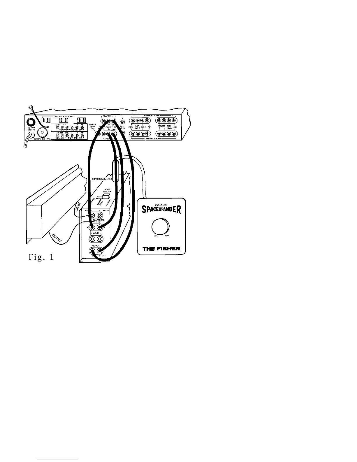
USING SPACEXPANDER JACKS ON FISHER INSTRUMENTS
There are no problems when making connections to a FISHER stereo instrument with
Spacexpander
interconnecting cables. DO NOT discard the jumpers (They can be handy when troubleshooting the
home music system). The jumpers
These jumpers complete the internal signal paths -without them the home music system will not
play; no sounds, except for a slight hiss or hum will be heard from the speakers.
jacks Just pullout the pair of horse-shoe shaped jumpers and insert the plugs of the
must
be reinserted when the
Spacexpander
CONNECTIONS
is disconnected.
Make the following connections between the
instrument
Spacexpander
jacks using 4 of the 6 audio interconnecting cables.
Spacexpander
Electronic Unit and the FISHER
• Left TO REVERB IN jack connected to
(left) A INPUT of
• Left TO REVERB OUT jack connected to
(left) A OUTPUT of
• Right TO REVERB IN jack connected to
(right) B INPUT of
• Right TO REVERB OUT jack connected to
(right) B OUTPUT of
Make the following connections between
the
Spacexpander
the Reverberation Chassis using 2 of the 6
audio interconnecting cables.
• INPUT jack of Reverberation Chassis to
jack marked TO INPUT OF REVERB UNIT
(chassis)
• OUTPUT jack of Reverberation Chassis to
jack marked to OUTPUT OF REVERB UNIT
• Set
Spacexpander
to NORMAL.
Spacexpander.
Spacexpander
Spacexpander.
Spacexpander.
Electronics Chassis and
MODE SELECTOR switch
.
Connecting to FISHER instruments with Spacexpander jacks is the easiest installation because
these instruments were designed to go together.
Page 3
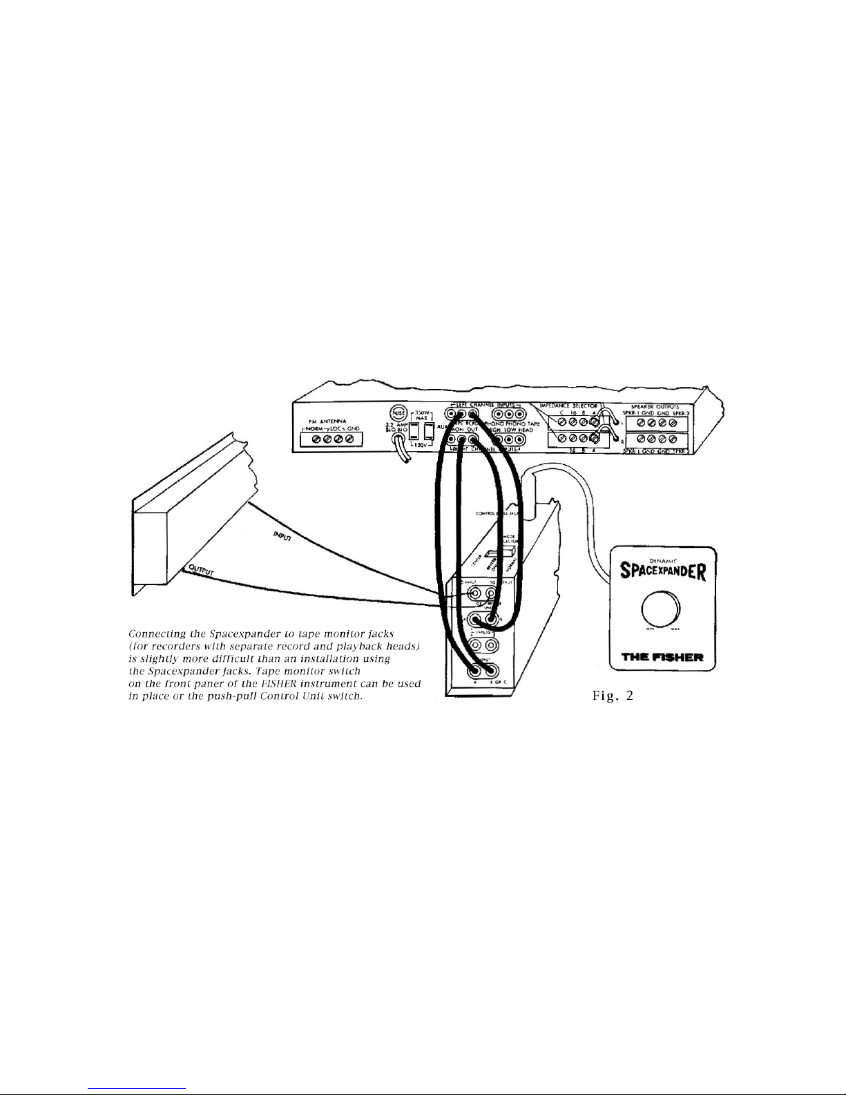
USING FISHER DIRECT TAPE MONITOR JACKS AND SIMILAR CIRCUITS
(for connecting Tape Recorders with separate Record and Playback heads).
The Direct Tape Monitor jacks are connected into the circuit in almost the exact same manner as
the
Spacexpander
selected by a front panel switch.
CONNECTIONS
The OUTPUT jacks, on the home music system instrument, may have exotic trade names or may be
labeled simply, like TAPE OUT, RCRDR OUT, etc. These jacks are connected to the A (left) and B
(right) inputs of the
jacks with but one exception -the jacks do not need jumpers because they are
Spacexpander.
Spacexpander
may be labeled MONITOR, MON, TAPE MON, TAPE IN, TAPE PLAY, etc., Make sure that the cables are
not crossed -the right-channel cables must connect to the right-channel jacks (and left to left)
throughout the system.
Make sure Spacexpander MODE SELECTOR switch Is set to NORMAL position for first listening tests,
Set DIRECT TAPE MONITOR switch to ON position.
OUTPUTs, A (left) and B (right), are connected to the home music system jacks that
SEPARATE PREAMPLIFIER/POWER AMPLIFIER CONNECTIONS
When separate control-preamplifier and power amplifier units are used in a home music system it
is just as easy to connect the
interconnecting cables between the control-preamplifier
about the same electrical connections as the horse-shoe shaped jumpers in the FISHER
instruments with the
With some home music system components a slight increase in the audible hiss level may be
noticed This noise level
amplifier chassis (when such a control is provided). The outputs from the control preamplifier
must
be increased to as high a level as possible (without distorting or unbalancing the sound
heard from the speakers
Spacexpander
Spacexpander
can
be reduced by turning down the input-level controls on the power
jacks.
as when
Spacexpander
and
jacks
power amplifier units make just
are
provided The
Page 4
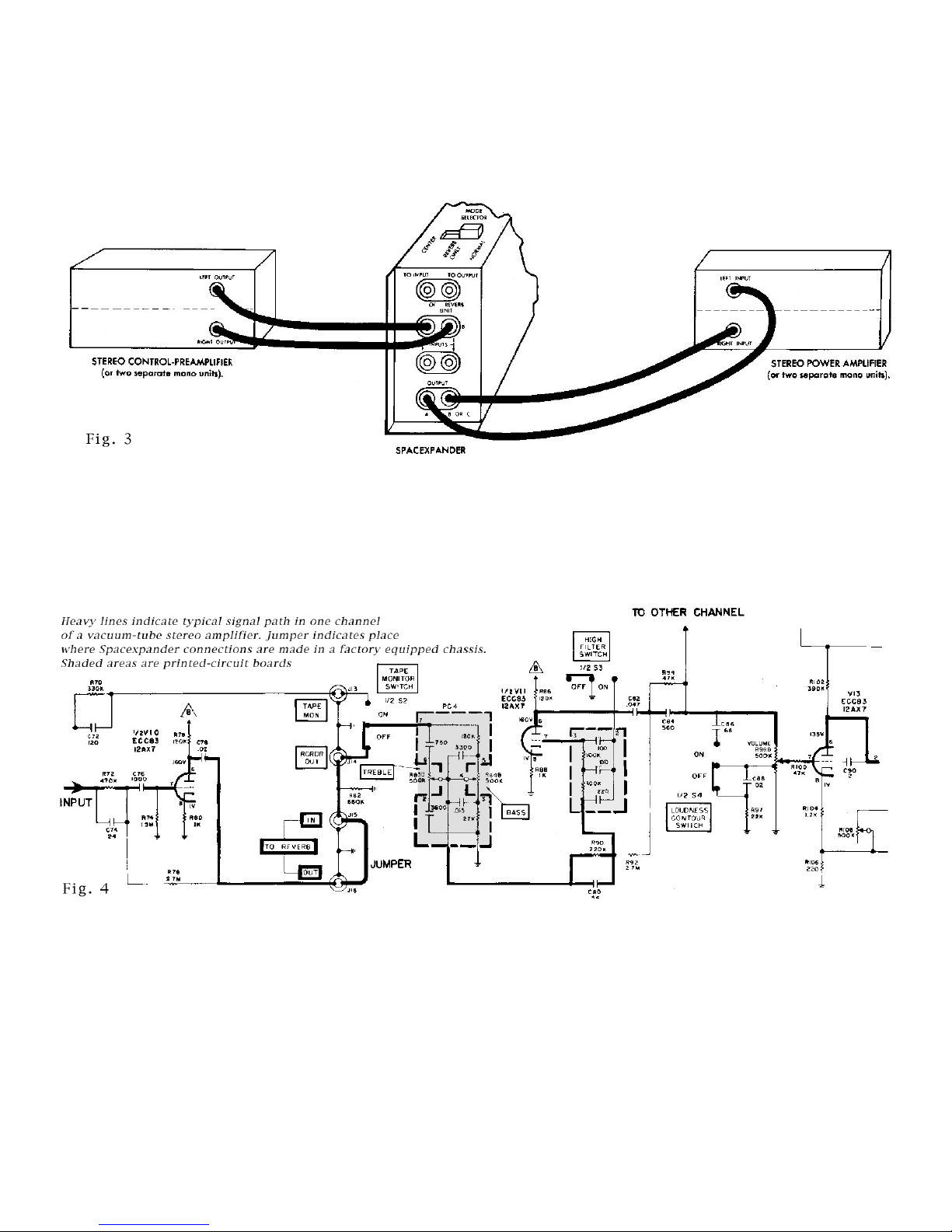
CONNECTIONS
For a home music system using separate control-preamplifier and power amplifier make the
following connections to the
Spacexpander;
• Control-preamp LEFT OUTPUT connected to
• Control-preamp RIGHT OUTPUT connected to
• Spacexpander
• Spacexpander
A OUTPUT connected to power amplifier LEFT INPUT jack.
B OUTPUT connected to power amplifier RIGHT INPUT jack
ADDING SPACEXPANDER JACKS
Jacks for
decide
schematics
Spacexpander
where
are
interconnecting cables can be added to most home music systems -just
to break into the signal path and
indicated by the heavy line.).
Spacexpander
Spacexpander
where
A INPUT jack.
B INPUT jack.
to mount the jacks (The signal paths in both
Actually it is not necessary to install jacks. Where space is limited the cables can be wired directly
into the circuit. Plugs on the
connector
jumper used to com
DO NOT wire the cables directly into the circuit without providing strain relief of
terminals are not strong enough to withstand much pulling and repeated twisting of the cables
will break the conductors of the cable where they are soldered to the home music system circuitry.
Modern home music systems may be either vacuum tube or transistor types (or a combination of
both) and may use printed circuits as well as point-to-point wiring. Printed circuitry in the two
schematics in this section has been shaded. The transistor home music system uses much more
printed circuitry.
can
be used to connect the two plugs together to take the place of the horse-shoe shaped
plete the circuit with factory-installed
other
ends will go into the
Spacexpander
Spacexpander
jacks. A feed
lacks.
through
some
sort. Solder
Page 5

Printed circuits are more difficult to work with - but not impossible The foil can be cut and small
sections removed to isolate one circuit from the following one - you need only a sharp knife or a
single-edged razor blade If you make a mistake the cut connections can be repaired Just solder a
thin piece of copper wire across the cut in the foil.
If you are not certain where the best point to connect the is write
Relations Department, Fisher Radio Corporation, Long Island City, New York,
include a schematic diagram of your unit .It will be returned with the proper connections
indicated
Richard Hamilton, Customer
11101,
You
must
Transistor stereo channel has similar signal path that is completed by jumper until Spacexpander
is connected .
PRECAUTIONS
• Disconnect line cord
• Remove all input and output cables connected to the chassis before working on circuit
modifications
• Never cut the pig-tail leads of components when there is another way of breaking the signal
path
• Never cut the pig-tail leads close to the body of the component.
• Double-check before you cut any conductor -either insulated wire or copper foil.
• Make clean, neat connectionsor permanent short circuits
• A low-heat soldering iron may not transfer heat fast enough to make good solder points- heat
conduction along the leads of components make heat sinks a necessity,
• Never use anything but rosin-core solder for connections.
• A too-hot soldering iron can ruin plastic parts of sockets and plugs, transistors and other
components as well as printed circuit boards.
WARNING:
extreme care. DO NOT attempt any modifications to high-fidelity instruments using this type of
construction unless you have had previous experience. It takes only a second or two to damage
expensive circuit components.
Transistors, printed circuitry and miniature components must be handled with
from
wall outlet before starting work on circuit modifications
any
frayed ends of wire or lumps of solder may cause intermittent
Page 6

THE CENTER CHANNEL AND THE SPACEXPANDER
Spacexpander
without any of the pure, original signal (MODE SELECTOR switch set to the REVERB ONLY position)
or with the pure signal and an adjustable amount of reverberated signal when the MODE SELECTOR
switch is set to the CENTER position. Try both positions before you decide where the MODE SELECTOR
switch will be set - you may find that your original choice does not give you the effect you
expected. Too much reverberation will give an unreal effect of a large, live, auditorium and
excessive echoes will make all tones and notes so fuzzy or blurred that they will run together and
be lost.
In the CENTER position the Control Unit knob will change the
the center-channel speakers - it wilt not change the volume, just the reverberation. When the
MODE SELECTOR switch is set to REVERB ONLY the Control Unit knob will act like a volume control
for the center channel. The only sound you hear from the center channel will be reverberated
sound. Since the Control Unit knob controls only the reverberated signal and there is no other
signal in this mode, the reverberated sound from the center-channel speaker increases and
decreases as the knob is rotated from the MINimum to MAXimum positions just like a volume
control.
center-channel reverberation can be used two ways - either full reverberation
amount
of reverberation heard from
Page 7

When a center-channel output has not been designed Into a unit, it can be created by the
Spacexpander.
as the signal source for the
complete the center channel. The
connected to a power amplifier, which. in turn
The tape recorder signal input plugs are then inserted into the other pair of input jacks on the
Spacexpander
Spacexpander,
it did when connected to the jacks on the high-fidelity instrument chassis. The material recorded
will not have reverberation added to it when you connect to these jacks Reverberation is added
after this point.
(See Fig. 7, previous page).
Spacexpander
Spacexpander
panel. The jacks for both A INPUTS and both B INPUTS are wired together, inside the
and the tape recorder will record the normal signal, without reverberation just as
Any output jacks for a stereo tape recorder can be used
Inputs. A power amplifier and a speaker are needed to
output cannot drive a speaker directly. It must be
,
is connected to the speaker
FINISHING THE INSTALLATION
No matter which electrical connections are best suited to your home music system equipment, and
your personal listening habits, the physical mounting of the Control Unit, Electronics Chassis and
Reverberation Chassis remains the same.
The most convenient mounting locations for the Electronics Chassis and the Reverberation chassis
may not be the best physical location for these units. While the Electronics Chassis may be
mounted in any position it is best to mount it with the tubes at the top. This way the heat will rise
away from the chassis, reducing the possibility of overheating the chassis and damaging any of
the circuit components that are wired inside.
Wherever possible the AC power cord should be plugged into an outlet on the home music system
equipment - an outlet that is turned
system. Accidentally leaving the
free life and cause the tubes to burn out sooner
Unit does not turn off the AC power to the
from being amplified. The pure (not reverberated) signal still is amplified by the
circuits.
The reverberation Chassis
mechanical device and its exact mounting is very critical (For a more complete explanation of the
method of operation of this critical mechanism read the section on HOW YOUR
WORKS.). Not only is the position of the Reverberation Chassis critical - so is its location.
It is subject to mechanical vibration - DO NOT mount it near the speakers The vibrations from the
speakers can vibrate the mechanical portions of the
amplified and heard from the speakers whose vibrations again will be picked up by the
mechanical portion of the
screech, whistle or groan, depending on
the speakers. Generally this effect will occur only when the Reverberation Chassis is mounted on
the back of a console cabinet - and then only when the instrument is played at high volume.
must
Spacexpander
on
and
off
by the same power switch that controls the whole
Spacexpander
be mounted against a vertical surface This unit is an electro
and amplified This
how slowly or how rapidly the vibrations get back from
on for many hours will only shorten its trouble
than necessary. The
Spacexpander
Component-type high-fidelity systems seldom
have mechanical feedback
speakers are usually separated from the
electronic equipment.
on-off
- it only stops the reverberated signal
Spacexpander
feedback
which, in turn, will be
quickly becomes a howl,
switch on the Control
Spacexpander
SPACEXPANDER
problems since the
-
-
When property installed, the Reverberation
Chassis will float on
normal conditions there will be no feedback.
NOT over tighten the wood screws through the
grommets, when mounting the Reverberation
Unit. Leave some freeplay - 1/32 inch is enough
Compressing the grommets reduces the
effectiveness of the shock mount assembly by
being too firm.
the shock mounts and, under
DO
Page 8

OPERATION
The two controls of the
your listening preference. The MODE SELECTOR switch on the Electronics Chassis is probably the
most important (and least used) control. Its position determines the way the reverberation is added
to the home music system You have your choice of three different effects.
Spacexpander
can be preset once you have selected positions that satisfy
MODE SELECTOR
NORMAL
none) as you want to your regular listening material - stereo or monophonic radio, tape, or
phono
amount of reverberation will increase from practically none to more than that usually heard in
an auditorium. Some place between these extremes is the amount of reverberation that creates
the illusion that is pleasing to you Once this point has been found you need never rotate the
knob again - except to demonstrate the
just pull up gently on the Control Unit knob until it clicks and all reverberation will be gone.
Push the knob down and you have the same amount of reverberation you originally selected
without hunting for a special adjustment
REVERB ONLY
effects THIS IS NOT A STEREOPHONIC MODE OF OPERATION. All signals coming out of the
Spacexpander
increase and decrease the sound from the speakers since there is
the knob can be set to the MAX position and forgotten because the volume control of the home
music system will now have the same effect on the operation of the home music system
push-pull switch on the Control Unit knob must be pressed in or
the speaker(s). In the REVERB ONLY position the sound heard will be an unnatural sound - just
echoes without any
hear normally, it is considered a special
sound in a center channel, it will blend with the normal sound from the left and right channel
speakers. This mode of operation will not create exactly the same sound quality as when the
MODE SELECTOR switch is in the NORMAL position and used for the center channel. The NORMAL
position produces a variable blend of the pure, original signal and the reverberated signal REVERB ONLY is just that: there is no pure, original signal to blend electronically, with the
reverberated signal and all you hear is the echo effect.
is used for most listening. In this position you can add as much reverberation (or
graph. As you rotate the Control Unit knob from MIN (minimum) to MAX (maximum) the
Spacexpander
is used mostly with center channel and monophonic systems or for special
in this MODE SELECTOR position are monophonic. The Control Unit knob will just
of the pure original sound. Since this is something that you
effect .But if you
to friends. To turn the reverberation
only
no sound will be heard from
use a small amount of this unnatural
a reverberated signal -
would never
.
off
The
CENTER
operation. The signal at OUTPUT A and OUTPUT B or C is the same. THIS IS NOT A STEREO
MODE OF OPERATION. Operation in this position is like that in NORMAL except it is not stereo. The
Control Unit knob blends the amount of reverberation, or turns it
the NORMAL position.
-this position of the MODE SELECTOR switch is also a monophonic output mode of
off
or
on.
CONTROL UNIT KNOB
In the NORMAL and CENTER positions of the MODE SELECTOR switch the Control Unit knob varies
the amount of
control plate indicate .The pure, original signal does not change volume as the control knob is
rotated. In the REVERB ONLY position of the MODE SELECTOR switch there is no pure, original
signal volume control on the home music system control panel.
Push-pull ON-OFF switch-
the knob out, until a slight click is heard, will stop the reverberation just as if you turned the
knob to The MIN position. Once you select the amount of reverberation you
pull action to turn it on and off without rotating the knob. THIS SWITCH DOES NOT TURN OFF THE
POWER TO THE ELECTRONICS UNIT - THE TUBES STAY LIGHTED. It only controls the reverberated
signals.
only
reverberation
the reverberated signal. Rotating the knob in this mode is like adjusting the
from MIN (minimum) to MAX (maximum) as the markings on The
Besides rotating, the Control Unit knob also moves in and out. Pulling
PHONIC
exactly as it does in
can use the push
-
Page 9

HOW THE SPACEXPANDER WORKS
The
Spacexpander,
It is separated into two major sections - an amplifier (Electronics Chassis) and a mechanical
transducer (the Reverberation Chassis). The control Unit is, electrically, part of the amplifier.
a result of many years of research and design is an electro-mechanical device.
The amplifier is not really an amplifier - because
of the losses in the isolation networks and the
Reverberation Chassis the overall gain (between
inputs and outputs) is about 1. All the amplifier
does is make up for the losses The volume control
setting of your home music system should be set to
just about the same setting whether the
Spacexpander
jumpers are in place.
is connected to the jacks or the
The heart of the
Reverberation Chassis. It is here that the delay,
echoes and decay are generated
echoes of a well-designed auditorium. A small
amount of the signals at the INPUT jacks (see block
diagram) are fed to V1 through the isolation
networks.
The output of V1 goes to the input of the
reverberation transducer. Here the electrical
signals are converted into a twisting, semi
mechanical motion. The movement of the
magnetic rods is transmitted along the springs.
The springs are not identical
are different too. Because of these differences, the motion produced by the magnetic rods takes 29
milliseconds (0.029 sec.) to reach the output end of one spring and 37 milliseconds to reach the
output end of the other. Here, the movement of the magnetic rods generates a very weak
reverberated signal which goes to an amplifier stage (V2) to be made stronger. Some of the
mechanical motion goes back along the springs. One echo returns to the starting point 58
milliseconds after it started and the other, traveling slower, returns to its input magnetic rod after
74 milliseconds (one millisecond is only 1/1000 of a second, remember). Again the rotational
mechanical motion, weaker than it was when it first started, heads for the output transducer These
second echoes arrive at the output transducer (and the output of V3) some 87 and 111 milliseconds
after the pure, original signal went through V3.
the wire sizes are not the same and the number of turns-to-the
Spacexpander
is the
they simulate the
rotary
inch
From one sound we have had five signals at the output jacks. The first echo of the original, pure
signal appeared 29 milliseconds later; another 37 milliseconds, a third after 87 milliseconds, a
fourth, after 111 milliseconds. Of course the mechanical reflections do not just stop after two
echoes (signals) have appeared at the output transducers - they continue, back and forth, getting
weaker each time until they cannot be heard. The number of reflections (echoes) heard will
depend on the setting of the Control Unit knob and the loudness of the original sound at the input
to the
Spacexpander.
TROUBLESHOOTING GUIDE
NO REVERBERATION monophono only
when listening to a monophonic record played with a stereo phonograph cartridge just reverse
the leads
inside the tone arm.
FEEDBACK
is turned slightly clockwise the Reverberation Chassis is either too close to the speakers or the
shock mount assembly has been over tightened (If this occurs after the
operating satisfactorily for some time it may indicate that the rubber has lost its resilience due to
(for one channel only)
-If the home music system moans, squeals or whistles whenever the Control Unit knob
. If there is no reverberation (or much less than usual)
where they attach to the terminals at the rear of the cartridge
Spacexpander
has been
Page 10

exposure to too
much heat or a chemical reaction to fumes, aerosol sprays or furniture polish.
Replace rubber grommets if they have become hard or gummy
HUM ADJUSTMENT
-The
Spacexpander
is adjusted at the factory, but after continued use, or
changing a vacuum tube, it may be necessary to change the adjustment:
To check for minimum hum.
• Set the home music system input SELECTOR to an unused position .Disconnect one pair of plugs
if all jacks are used.
• Turn the BASS and VOLUME controls to their maximum clockwise positions.
• Insert a screwdriver through the opening in the Electronics Chassis marked HUM ADJUST
• Rotate the shaft of the HUM ADJUST control for minimum hum from the speakers.
Does not go on (tubes do not light up).
Check:
• AC outlet (use test lamp).
• Line cord and plug.
Distortion (both channels) any position of MODE SELECTOR switch,
Hum, Weak or No audio output (Tubes light up.)
• Disconnect
Spacexpander
temporarily (reinsert jumpers) to be sure that other
components of home music system are operating normally
Check
Test
:
• HUM ADJUST control R11.
:
• V3
• Power supply for voltages at CR1, C5A R9; C5B, R9, R10; C5C, R10, R12; C5D, R12. V3
socket for proper voltages.
No reverberation (both channels) no audio output in REVERB ONLY position of MODE
SELECTOR switch. Hum, Weak or No REVERB output.
• Listen to voice -comedy or news
• Set Control Unit knob to MAX position.
• Push Control Unit knob down.
Check
:
• Control Unit plug and interconnecting cable.
• Reverberation Unit jacks, plugs and interconnecting cables
• R24 and S1 on Control Unit.
Test
• V1 and V2.
• V1 and V2 sockets for proper voltages
No reverberation (PHONO-MONO only)
• Check phasing of phono cartridge.
Reverberation only (no pure signal) any position of MODE SELECTOR switch.
• Set MODE SELECTOR to NORMAL position.
Check
:
• S2 for proper operation.
• Control Unit jack, plug and interconnecting cable.
• R24 and S1 in Control Unit.
Feed back (when system volume or Control Unit knob turned up.)
Check
"
• Shock mount assembly
Page 11

TECHNICAL SPECIFICATIONS
DELAY TIME
DECAY TIME
.......................................................
.......................................................
MINIMUM INPUT VOLTAGE REQUIRED
MAXIMUM ALLOWABLE INPUT VOLTAGE
INPUT IMPEDANCE
OUTPUT IMPEDANCE
OUTPUT VOLTAGE
GAIN
HUM LEVEL
...................................................................
........................................................
POWER CONSUMPTION
............................................
........................................
............................................
.....................................
..........
.....
33 milliseconds
2 seconds maximum at 300 cps
0.2 Volt
5 Volts
250K Ohms
2000 Ohms
02 - 5 Volts
Unity
80 db below 2.5 Volts
16 Watts
Page 12

Page 13

 Loading...