

Fisher GX Instruction Manual
Instruction Manual
D103175X012
GX Valve and Actuator
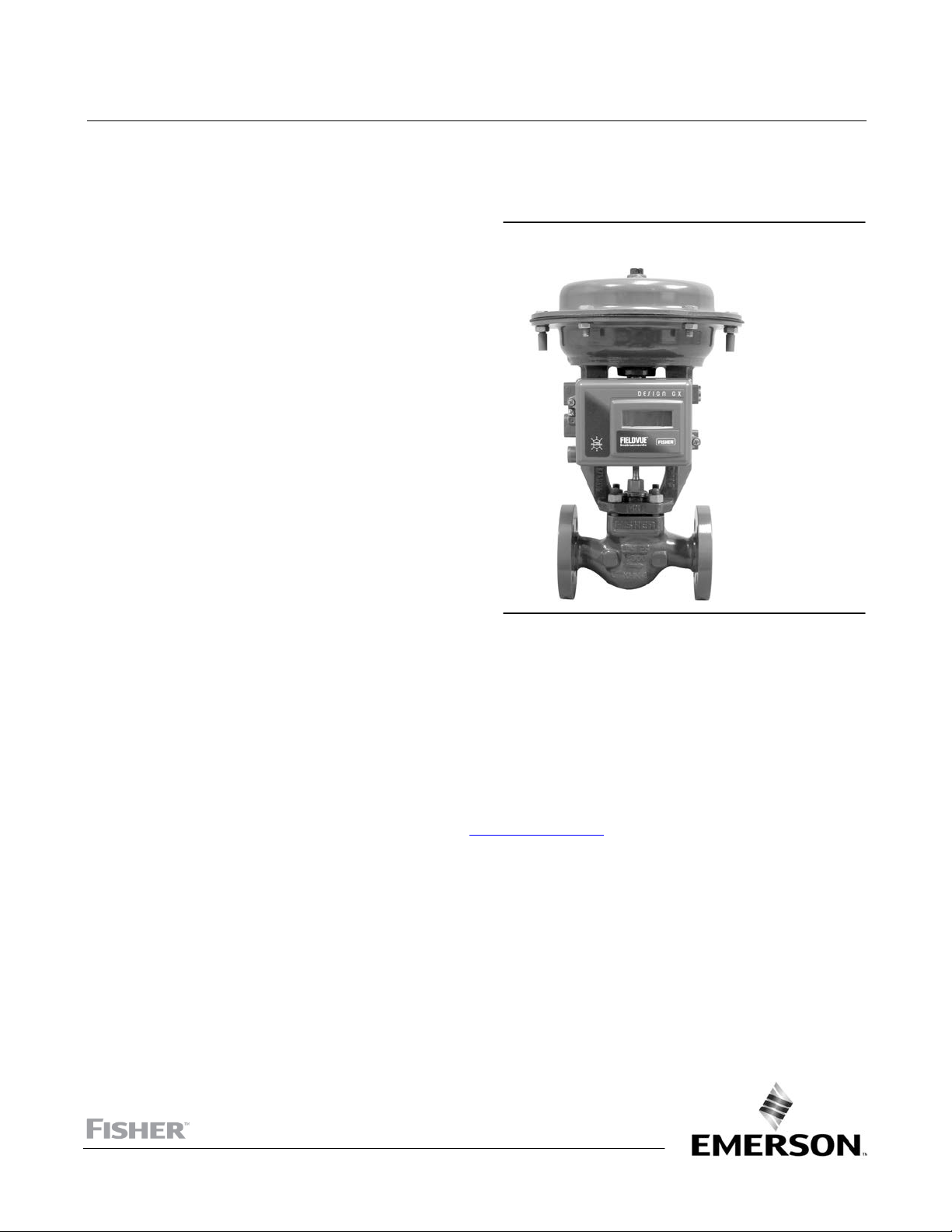
Fisher™ GX Control Valve and Actuator System
July 2017
Contents
Introduction 1.................................
Scope of Manual 1.............................
Description 1.................................
Specifications 2...............................
Educational Services 2.........................
Valve Installation 2.............................
Maintenance 4.................................
Actuator Maintenance 5........................
FIELDVUEt DVC2000 Digital Valve
Controller Mounting 11......................
Packing Maintenance 12........................
Replacing Packing (Pneumatic Actuators) 13.......
Replacing Packing (Electric Actuators) 16.........
Valve Trim Maintenance 19.....................
Bellows Maintenance 24........................
Handwheel Operation 25........................
Travel Stop Operation 26........................
Parts Ordering 41...............................
Parts Kits 42...................................
Parts List 43...................................
Introduction
Figure 1. Fisher GX Control Valve, Actuator, and
FIELDVUE DVC2000 Digital Valve Controller
W8861
Scope of Manual
This instruction manual includes installation, maintenance, and parts information for the Fisher GX control valve and
actuator system.
Do not install, operate, or maintain a GX valve without being fully trained and qualified in valve, actuator, and
accessory installation, operation, and maintenance. To avoid personal injury or property damage, it is important to
carefully read, understand, and follow all the contents of this manual, including all safety cautions and warnings. If you
have any questions about these instructions, contact your Emerson sales office
proceeding.
or Local Business Partner before
Description
The GX is a compact, state‐of‐the‐art control valve and actuator system, designed to control a wide range of process
gases, vapors, and fluids.
The GX is rugged, reliable, and easy to select. It requires no actuator sizing ‐‐ the actuator selection is automatic once
the valve body construction is selected.
The GX meets the requirements of both EN and ASME standards. It is available with a complete accessory package,
including the FIELDVUE DVC2000 integrated digital valve controller.
www.Fisher.com
GX Valve and Actuator
July 2017
Table 1. Fisher GX Valve Specifications
Specifications EN ASME
Valve Body Size DN15, 20, 25, 40, 50, 80, 100, 150 NPS 1/2, 3/4, 1, 1-1/2, 2, 3, 4, 6
Pressure Rating PN 10 / 16 / 25 / 40 per EN 1092-1 CL150 / 300 per ASME B16.34
End Connections Flanged raised face per EN 1092-1 Flanged raised face per ASME B16.5
1.0619 steel ASME SA216 WCC steel
1.4409 stainless steel ASME SA351 CF3M stainless steel
CW2M (sizes DN25 through DN100 only) CW2M (NPS 1 through 4 only)
ASME SA352 LCC ASME SA352 LCC
ASTM A990 CN3MCu/ASME SA351 CN7M (Cast Alloy 20)
Valve Body/Bonnet Materials
Face-to-Face Dimensions
Shutoff per IEC 60534-4
and ANSI/FCI 70-2
Flow Direction Flow-up (Cavitrol™ III trim, Flow down)
Flow Control Characteristics Equal Percentage and Linear
Trim Style
Handwheel Available as an option
Travel Stop Available as an option
1. For 4.8 to 14 mm ports, Class VI shutoff is achieved without PTFE seat.
(sizes DN25 through DN100 only)
CD3MN Duplex SST
(sizes DN25 through DN100 only)
CF3 304L SST
(sizes DN25 through DN100 only)
Consistent with EN 558-1 Series 1
Metal seat - Class IV (standard)
Metal seat - Class V (optional)
PTFE seat - Class VI (optional)
Port Diameters Trim Style Description
4.8 mm Micro-Flow trim (unbalanced)
9.5, 14, 22 mm
36, 46 mm Port-Guided Plug (unbalanced)
70, 90, 136 mm Balanced Trim with Contoured plug or Unbalanced Port-Guided Plug
ASTM A990 CN3MCu/ASME SA351 CN7M (Cast Alloy 20)
Stem-Guided with Contoured Plug (unbalanced)
or Port-Guided with Cavitrol III trim (unbalanced)
Instruction Manual
D103175X012
(NPS 1 through 4 only)
CD3MN Duplex SST
(NPS 1 through 4 only)
CF3 304L SST
(NPS 1 through 4 only)
M35-2 (NPS 1 through 4 only)
N7M Alloy B2
(NPS 1 through 4 only)
Consistent with ANSI/ISA 75.08.01
(1)
Educational Services
For information on available courses for the Fisher GX valve and actuator system, as well as a variety of other products,
contact:
Emerson Automation Solutions
Educational Services - Registration
Phone: 1-641-754-3771 or 1-800-338-8158
E-mail: education@emerson.com
emerson.com/fishervalvetraining
Valve Installation
WARNING
Always wear protective gloves, clothing, and eyewear when performing any installation operations to avoid personal
injury.
2
Instruction Manual
D103175X012
GX Valve and Actuator
July 2017
Personal injury or equipment damage caused by sudden release of pressure or bursting of pressure retaining parts might
result if service conditions exceed those for which the product was intended. To avoid injury or damage, provide a relief
valve for over pressure protection as required by government or accepted industry codes and good engineering practices.
Check with your process or safety engineer for any additional measures that must be taken to protect against process
media.
If installing into an existing application, also refer to the WARNING at the beginning of the Maintenance section in this
instruction manual.
CAUTION
This valve is intended for a specific range of pressures, temperatures and other application specifications. Applying
different pressure and temperatures to the valve could result in parts damage, malfunction of the control valve or loss of
control of the process. Do not expose this product to service conditions or variables other than those for which the product was
intended. If you are not sure what these conditions are you should contact your Emerson sales office
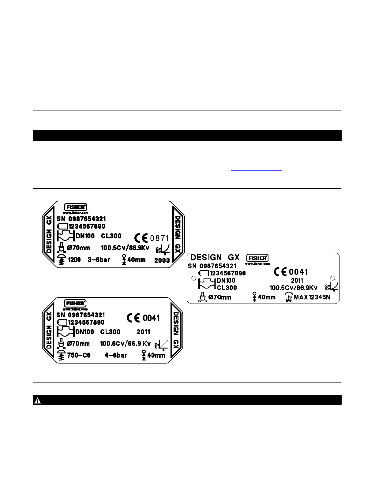
Partner for more complete specifications. Provide the product serial number (shown on the nameplate, figure 2) and all
other pertinent information.
Figure 2. Fisher GX Nameplate Examples (Key 35)
or Local Business
GE01296‐H
GE41229-Sheet 1
WITHOUT SPRING INFORMATION
(USED PRIOR TO 2009)
WITH SPRING INFORMATION
GG12198-A
ELECTRIC ACTUATOR
WARNING
If you move or work on an actuator installed on a valve with loading pressure applied, keep your hands and tools away from
the stem travel path to avoid personal injury. Be especially careful when removing the stem connector to release all loading
on the actuator stem whether it be from air pressure on the diaphragm or compression in the actuator springs. Likewise
take similar care when adjusting or removing any optional travel stop. Refer to the relevant actuator Maintenance
Instructions.
3

GX Valve and Actuator
July 2017
If hoisting the valve take care to prevent people from being injured in case the hoist or rigging slips. Be sure to use
adequately sized hoists and chains or slings to handle the valve.
Instruction Manual
D103175X012
1. Before installing the valve, inspect it to be certain that the valve body cavity is free of all foreign material. Clean out
all pipelines to remove scale, welding slag and other foreign material.
2. The control valve assembly may be installed in any orientation unless limited by seismic criteria. However, the
normal method is with the actuator vertical above the valve. Other positions may result in uneven trim wear, and
improper operation. With some valves, the actuator may also need to be supported when it is not vertical. For more
information, consult your Emerson sales office
or Local Business Partner. Flow through the valve must be in the
direction indicated by the arrow cast on the valve.
3. Use accepted piping practices when installing the valve in the pipeline. Use a suitable gasket between the valve and
the pipeline flanges.
4. If continuous operation is required during inspection or maintenance, install isolating valves on either side of the
control valve with a bypass valve to control the flow while the control valve is receiving maintenance.
WARNING
Personal injury could result from packing leakage. Valve packing is tightened before shipment; however the packing might
require some readjustment to meet specific service conditions.
Maintenance
WARNING
Avoid personal injury or property damage from sudden release of process pressure or bursting of parts. Before performing
any maintenance operations:
D Do not remove the actuator from the valve while the valve is still pressurized.
D Always wear protective gloves, clothing, and eyewear when performing any maintenance operations to avoid personal
injury.
D Disconnect any operating lines providing air pressure, electric power or a control signal to the actuator. Be sure the
actuator cannot suddenly open or close the valve.
D Use bypass valves or completely shut off the process to isolate the valve from the process pressure. Relieve the process
pressure from both sides of the valve.
D Depending on the actuator construction, it will be necessary to manage the pneumatic actuator loading pressure and
any actuator spring pre‐compression. It is essential to refer to the relevant actuator instructions in this manual to
ensure safe removal of the actuator from the valve.
D Use lock‐out procedures to be sure that the above measures stay in effect while you work on the equipment.
D The valve packing box may contain process fluids that are pressurized, even when the valve has been removed from the
pipeline. Process fluids may spray out under pressure when removing the packing hardware or packing rings, or when
loosening the packing box pipe plug.
D Check with your process or safety engineer for any additional measures that must be taken to protect against process
media.
Note
Whenever a gasket seal is disturbed by removing or shifting gasketed parts, install a new gasket during reassembly. This ensures a
good gasket seal because the used gasket may not seal properly.
4
Instruction Manual
D103175X012
GX Valve and Actuator
July 2017
Actuator Maintenance
For electric actuators, see the supplier's instruction manual.
The following sections provide procedures for actuator maintenance. Refer to figures 18, 19, 20, and 21.
The actuator soft parts may require periodic replacement. This includes the diaphragm (key 10), diaphragm O-ring
(key 109), actuator rod bushing (key 19), and the actuator rod seal (key 20).
If the actuator stroking direction (air‐to‐open or air‐to‐close) is unknown, refer to the nameplate on top of the actuator
casing and figure 2.
There are several optional actuator constructions, depending on supply pressure. Refer to the nameplate on the top of
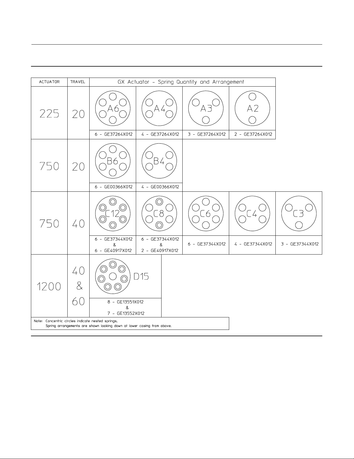
the actuator to determine the construction installed. Refer to figure 3 and table 2 for proper spring configuration.
Note
Older GX actuator nameplates do not contain spring configuration information. If you require replacement springs or wish to
switch to an optional actuator construction, consult your Emerson sales office
or Local Business Partner.
Note
When the GX actuator is equipped with the integrated FIELDVUE DVC2000 digital valve controller (figure 1), additional
considerations may be required. Refer to the FIELDVUE DVC2000 Digital Valve Controller Mounting section of this manual for
additional instruction.
Actuator Disassembly (For Air‐to‐Open Constructions ‐ see figures 18 or 19)
1. Connect a separate air supply to the lower diaphragm casing via the air supply connection on the yoke (as shown in
figure 18 or 19) and apply sufficient air pressure to raise the valve plug/stem off the seat to mid‐travel.
2. Remove the stem connector nut half (key 23), stem connector bolt half (key 24), and travel indicator (key 26).
3. Push the valve plug/stem (key 3) down until it contacts the seat.
4. Loosen the locknut (key 28) and thread the stem adjustor nut (key 27) down until it clears the top of the valve
plug/stem (key 3).
5. Shut off the air pressure and disconnect the separate air supply to the lower diaphragm casing (as shown in figure
18 or 19).
WARNING
To avoid personal injury or property damage due to actuator springs (keys 12 and 82) being under compression, remove the
long cap screws (key 16) last.
The upper actuator casing may remain fixed to the diaphragm and lower casing during disassembly, even if the casing cap
screws have been loosened. If this happens, the actuator springs are still under compression. The upper casing could
suddenly come loose and jump, due to the compressed energy of the springs. If the upper casing is stuck to the diaphragm
and lower casing when you begin loosening the casing cap screws, pry the casings apart with a prying tool. Always ensure
that the springs are dispersing energy and the upper casing is moving against the long bolts during disassembly.
5
GX Valve and Actuator
July 2017
Figure 3. Spring Configuration
Instruction Manual
D103175X012
GG00398-B
6. Remove the short actuator casing cap screws and hex nuts (keys 17 and 18) first. Once these have been removed
from the actuator assembly, carefully remove the long actuator cap screws and hex nuts (keys 16 and 18),
alternating between them to gradually release the spring energy (compression).
7. Remove the upper diaphragm casing (key 9) and the actuator springs (key 12 and/or 82).
8. Lift off the actuator stem/diaphragm assembly (includes keys 22, 11, 10, 14, 13, 109, and 15) and remove the cap
screw (key 14), actuator spacer (key 13), actuator rod (key 22), and washer (key 15).
9. Replace the diaphragm (key 10), diaphragm O-ring (key 109), actuator rod bushing (key 19), and actuator rod seal
(key 20), as needed.
6
Instruction Manual
D103175X012
GX Valve and Actuator
July 2017
Actuator Disassembly (For Air‐to‐Close Constructions ‐ see figure 20 or 21)
1. Remove the stem connector nut half (key 23), stem connector bolt half (key 24), and travel indicator (key 26).
WARNING
To avoid personal injury or property damage due to actuator springs (key 12) being under compression, remove the long
cap screws (key 16) last.
The upper actuator casing may remain fixed to the diaphragm and lower casing during disassembly, even if the casing cap
screws have been loosened. If this happens, the actuator springs are still under compression. The upper casing could
suddenly come loose and jump, due to the compressed energy of the springs. If the upper casing is stuck to the diaphragm
and lower casing when you begin loosening the casing cap screws, pry the casings apart with a prying tool. Always ensure
that the springs are dispersing energy and the upper casing is moving against the long bolts during disassembly.
2. Remove the short actuator casing cap screws and hex nuts (keys 17 and 18) first. Once these have been removed
from the actuator assembly, carefully remove the long actuator cap screws and hex nuts (keys 16 and 18),
alternating between them to gradually release the spring energy (compression).
3. Remove the upper diaphragm casing (key 9).
4. Lift off the actuator stem/diaphragm assembly (includes keys 22, 11, 10, 14, 13, 109, and 15) and remove the cap
screw (key 14), actuator spacer (key 13), actuator rod (key 22), and washer (key 15).
5. Remove the actuator springs (key 12 and/or 82).
6. Replace the diaphragm (key 10), diaphragm O-ring (key 109), actuator rod bushing (key 19), and actuator rod seal
(key 20), as needed.
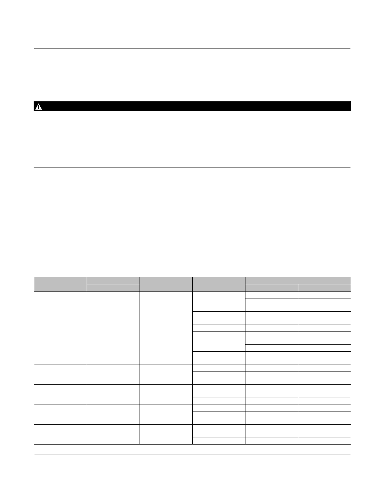
Table 2. Actuator Spring Configuration Based on Minimum Supply Pressure
ACTUATOR SIZE
225 20
225 20
750 20
750 20
750 40
750 40
1200 40 or 60
1. Only applicable to actuators with spring information on the nameplate (see figure 2).
2. Only applicable to Cavitrol III constructions.
TRAVEL
mm Air‐to‐Open Air‐to‐Close
STEM MATERIAL
S20910, N05500
S31603
S31803, N10675,
N06022
S20910, N05500
S31603
S31803, N10675,
N06022
S20910, N05500
S31603
S31803, N10675,
N06022
S20910, N05500
S31603
MINIMUM SUPPLY
PRESSURE
4 bar (58 psi)
3 bar (44 psi) A4 A3
2 bar (29 psi) A3 A2
4 bar (58 psi) A6 A3
3 bar (44 psi) A4 A3
2 bar (29 psi) A3 A2
4 bar (58 psi)
3 bar (44 psi) B6 B4
2 bar (29 psi) B4 B4
4 bar (58 psi) B4 B4
3 bar (44 psi) B4 B4
2 bar (29 psi) B4 B4
4 bar (58 psi) C12 C6
3 bar (44 psi) C8 C3
2 bar (29 psi) C4 C3
4 bar (58 psi) C8 C6
3 bar (44 psi) C8 C3
2 bar (29 psi) C4 C3
4 bar (58 psi) D15 D15
3 bar (44 psi) D15 D15
2 bar (29 psi) N/A N/A
(1)
SPRING CONFIGURATION
A6 A3
(2)
A4
B6 B4
(2)
B6
A4
B6
(2)
(2)
7
GX Valve and Actuator
July 2017
Instruction Manual
D103175X012
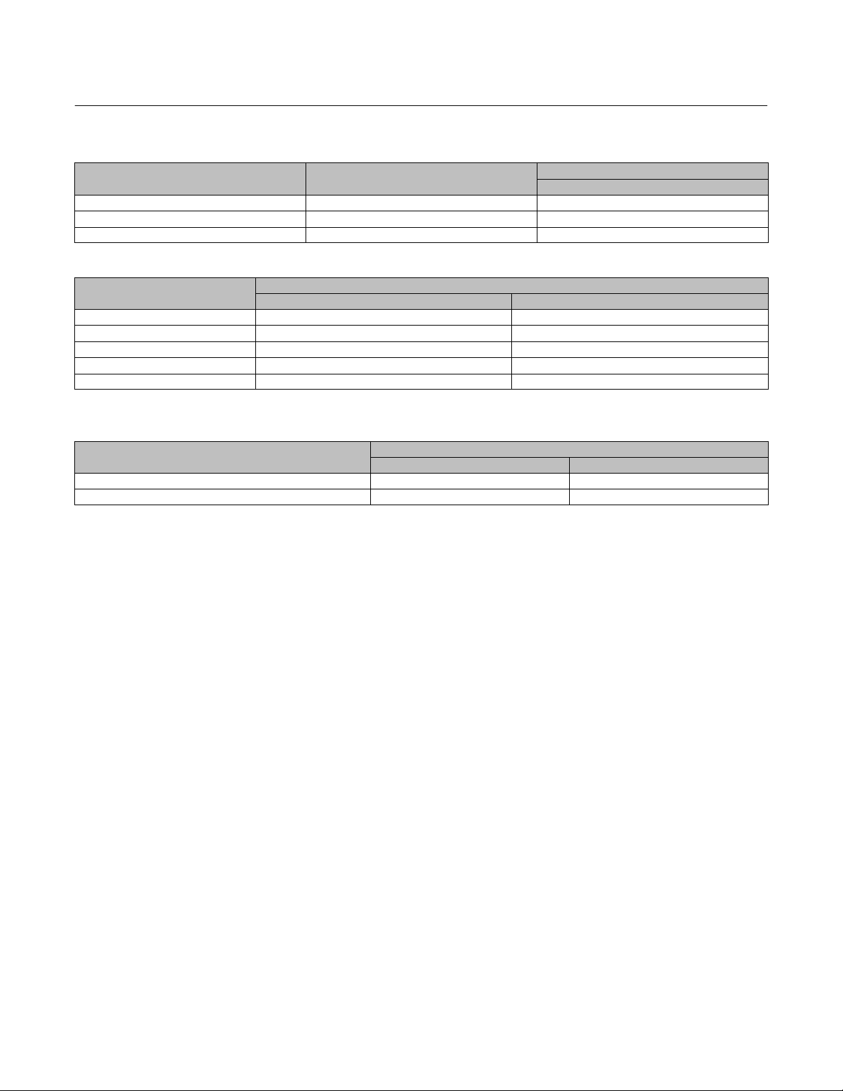
Table 3. Fisher GX Maximum Rated Travel
ACTUATOR SIZE NUMBER OF CASING BOLTS
225 6 20
750 10 20 or 40
1200 16 40 or 60
TRAVEL
mm
Table 4. Body Nut (Key 7) Torque Requirements
VALVE SIZE
DN15, 20, 25 (NPS 1/2, 3/4, 1) 45.5 33.5
DN40 (NPS 1‐1/2) 79.8 58.9
DN50 (NPS 2) 79.8 58.9
DN80 (NPS 3) 163 120
DN100 and DN150 (NPS 4 and 6) 282 208
NSm lbfSft
TORQUE
Table 5. Yoke/Extension Bonnet Nut (Key 46) Torque Requirements (used on Extension Bonnet and Bellows Bonnet
constructions)
VALVE SIZE
DN15, 20, 25, 40, and 50 (NPS 1/2, 3/4, 1, 1‐1/2, and 2) 79.8 58.9
DN80 and DN100 (NPS 3 and 4) 163 120
NSm lbfSft
TORQUE
Actuator Assembly For Air‐to‐Open Constructions (or to Change Action to Air‐to‐Open ‐ see
figure 18 or 19)
1. Install the diaphragm (key 10) on the diaphragm plate (key 11). Insert the cap screw (key 14) through the actuator
spacer (key 13) and place this assembly through the diaphragm/diaphragm plate assembly.
2. Place the diaphragm O-ring (key 109) and the washer (key 15) over the center hole of the diaphragm, so that the
convex part of the washer is facing down toward the diaphragm and contains the O-ring. Ensure the convex part of
the washer is guided in the diaphragm center hole as shown in figure 18 or 19.
3. Screw the actuator rod (key 22) onto the cap screw (key 14) and torque to 80 NSm (59.1 lbfSft). Install the actuator
stem/diaphragm assembly back into the actuator yoke (key 8).
4. Place the actuator springs (key 12 and/or 82) onto the spring locators in the diaphragm plate (key 11). See figure 3
and table 2 for proper spring quantity and arrangement.
D If the nameplate does not contain spring information, use the same quantity and arrangement as originally
installed.
5. Install the upper diaphragm casing (key 9) so that the ribs on the top of the upper diaphragm casing are
perpendicular with the yoke legs.
D For size 225 and 750 actuators, install the 2 long cap screws (key 16) and hex nuts (key 18) 180 degrees apart from
each other and in line with the actuator yoke legs.
D For size 1200 actuators, install the 4 long cap screws (key 16) and hex nuts (key 18) 90 degrees from each other,
with two of them in line with the actuator yoke legs.
6. Tighten the long cap screws (key 16) and hex nuts (key 18), alternating between them to gradually compress the
springs, until the two casing halves and diaphragm touch.
7. Install the remaining short cap screws (key 17) and hex nuts (key 18) to the casing.
8. Tighten the actuator casing cap screws evenly using a cross‐tightening procedure. Torque to 55 NSm (40 lbfSft).
8

Instruction Manual
D103175X012
GX Valve and Actuator
July 2017
9. If you had previously removed the actuator assembly from the valve, place the actuator assembly back onto the
valve body (key 1). Install the four body nuts (key 7), but tighten them only finger‐tight.
10. Connect a separate air supply to the actuator air supply connection (as shown on the yoke in figure 18 or 19) and
apply sufficient air pressure to raise the actuator rod (key 22) to the travel stop.
Note
If converting from air‐to‐close to air‐to‐open action, first move the vent cap (key 21) from the air supply connection on the yoke
leg (see figure 20 or 21) to the top of the casing (see figure 18 or 19).
11. For standard bonnet constructions (figures 18, 19, 20, and 21), tighten the body nuts (key 7) evenly using a
cross‐tightening procedure. See table 4 for torque requirements.
For extension and bellows bonnet constructions (figures 22 and 23), tighten the bonnet nuts (key 46) evenly using a
cross‐tightening procedure. See table 5 for torque requirements.
12. With the valve plug/stem (key 3) on the seat, thread the stem adjustor nut (key 27) up until it is the rated travel
distance specified in table 3 from the actuator rod (key 22). Thread the locknut (key 28) up against the stem locknut
and tighten per table 6.
Table 6. Stem Connector Torque Values
PART STEM MATERIAL
M8 Stem Connector Cap Screws All 35 26
M10 Stem Connector Jam Nut
(Rie 4606 Coated)
M14 Stem Connector Jam Nut
S31603, S20910, N05500 48 35
N06022, S31803, N10675 35 26
S31603, S20910, N05500 175 129
N06022, S31803, N10675 138 102
NSm LbfSft
TORQUE
13. Stroke the actuator rod until it contacts the stem adjuster nut (key 27) and install the stem connector halves and
travel indicator (keys 23, 24, and 26) with the cap screws (key 25). Install the stem connector halves in the proper
orientation so that when looking at the inside of the stem connector halves, the flats are down and the beveled
surfaces are up.
14. Align the pointer of the travel indicator (key 26) with the appropriate mark on the travel scale.
15. Tighten the stem connector cap screws (key 25) to 35 NSm (26 lbfSft).
16. Release the actuator pressure.
Note
For air‐to‐open action, the air supply tubing must be connected to the actuator yoke at the air supply connection, see figure 18 or
19. (If converting from air‐to‐close to air‐to‐open, the tubing will need to be re‐routed to this location).
Actuator Assembly For Air‐to‐Close Constructions (or to Change Action to Air‐to‐Close ‐ see
figure 20 or 21)
1. Position the upper diaphragm casing (key 9) upside down on the bench so that it lays flat and not off balance.
Note
If converting from air‐to‐open to air‐to‐close action, first move the vent cap (key 21) from the top of the casing (see figure 18 or
19) and thread into the air supply connection on the yoke leg (see figure 20 or 21).
9

GX Valve and Actuator
July 2017
Instruction Manual
D103175X012
2. Install the diaphragm (key 10) on the diaphragm plate (key 11). Place the diaphragm O-ring (key 109) and the
washer (key 15) over the center hole of the diaphragm, so that the convex part of the washer is facing down toward
the diaphragm and contains the O-ring. Ensure the convex part of the washer is guided in the diaphragm center
hole as shown in figure 20 or 21.
3. Insert the cap screw (key 14) through the washer and diaphragm, install the actuator spacer (key 13), and screw the
actuator rod (key 22) onto the cap screw (key 14) finger‐tight.
4. Radially align the spring locators in the diaphragm plate assembly (key 11) with the casing cap screw holes in the
diaphragm (key 10). This will ensure that the springs do not cover the air path in the yoke.
5. Torque the cap screw (key 14) to the actuator rod (key 22) to 80 NSm (59.1 lbfSft) and lay this assembly into the
upper diaphragm casing (key 9).
6. Place the actuator springs (key 12 and/or 82) onto the spring locators in the diaphragm plate (key 11). See figure 3
and table 2 for proper spring quantity and arrangement.
D If the nameplate does not contain spring information, use the same quantity and arrangement as originally
installed.
7. Remove and replace the actuator rod bushing (key 19) and actuator rod seal (key 20) in the actuator yoke (key 8), if
necessary.
8. Set the actuator yoke (key 8) down onto the assembly that is resting in the upper diaphragm casing (key 9) so that
the yoke legs are perpendicular with the ribs on the top of the upper diaphragm casing (key 9).
D For size 225 and 750 actuators, install the 2 long cap screws (key 16) and hex nuts (key 18) 180 degrees apart from
each other and in line with the actuator yoke legs.
D For size 1200 actuators, install the 4 long cap screws (key 16) and hex nuts (key 18) 90 degrees from each other,
with two of them in line with the actuator yoke legs.
9. Tighten the long cap screws (key 16) and hex nuts (key 18), alternating between them to gradually compress the
springs, until the two casing halves and diaphragm touch.
10. Install the remaining short cap screws (key 17) and hex nuts (key 18) to the casing.
11. Tighten the actuator casing cap screws evenly using a cross‐tightening procedure. Torque to 55 NSm (40 lbfSft).
12. If you had previously removed the actuator assembly from the valve, place the actuator assembly back onto the
valve body (key 1). For standard bonnet constructions (figures 18, 19, 20, and 21), install the body nuts (key 7) and
tighten evenly using a cross‐tightening procedure. See table 4 for torque requirements.
For extension and bellows bonnet constructions (figures 22 and 23), install the bonnet nuts (key 46) and tighten
evenly using a cross‐tightening procedure. See table 5 for torque requirements.
13. With the valve plug/stem (key 3) in the closed position (on the seat), thread the stem adjustor nut (key 27) up until
it is at the rated travel (see table 3) from the actuator rod (key 22). Thread the locknut (key 28) up against the stem
locknut and tighten per table 6.
14. Stroke the actuator rod until it contacts the stem adjuster nut (key 27) and install the stem connector halves and
travel indicator (keys 23, 24, and 26) with the cap screws (key 25). Install the stem connector halves in the proper
orientation so that when looking at the inside of the stem connector halves, the flats are down and the beveled
surfaces are up.
15. Align the pointer of the travel indicator (key 26) with the appropriate mark on the travel scale.
16. Tighten the stem connector cap screws (key 25) to 35 NSm (26 lbfSft).
Note
For air‐to‐close action, the air supply tubing must be connected to the actuator upper casing at the air supply connection, see
figure 20 or 21. (If converting from air‐to‐open to air‐to‐close, the tubing will need to be re‐routed to this location).
10
Instruction Manual
D103175X012
GX Valve and Actuator
July 2017
FIELDVUE DVC2000 Digital Valve Controller Mounting
This section provides instruction on mounting the FIELDVUE DVC2000 digital valve controller to the GX control valve.
For further detail on the operation and maintenance of the DVC2000, refer to the DVC2000 instruction manual.
The FIELDVUE DVC2000 digital valve controller mounts directly to an interface pad on the GX actuator yoke leg,
eliminating the need for mounting brackets (see figure 1). Internal passageways in the actuator route the pneumatic
output to the actuator casing, which eliminates the need for external air supply tubing in the air‐to‐open
(spring‐to‐close) constructions. (The GX will also accommodate other valve positioners, using the NAMUR mounting
pads on the side of the yoke legs.)
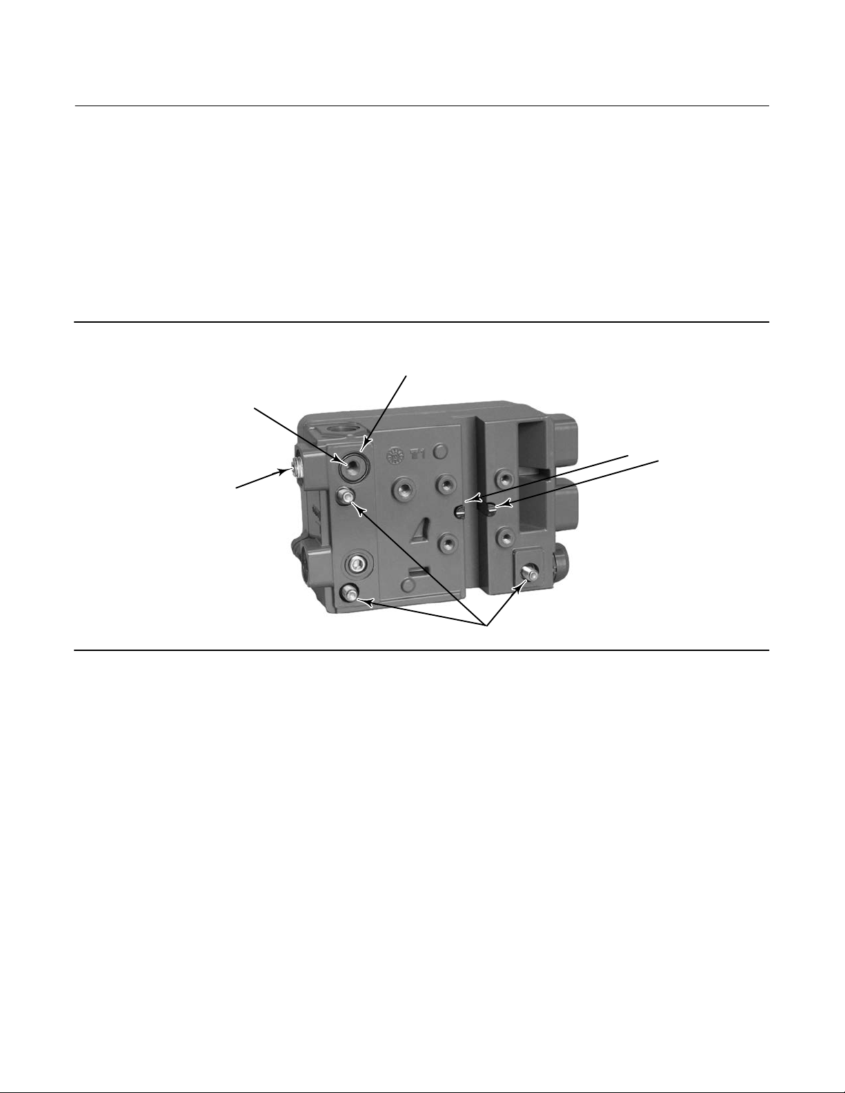
Figure 4. DVC2000 Digital Valve Controller Mounting Details
FOR AIR‐TO‐OPEN, INSTALL THE O‐RING SEAL BEFORE
B: INTEGRAL MOUNTING
PNEUMATIC OUTPUT PORT
(R1/8 PLUG)
MOUNTING TO THE GX ACTUATOR
POLE PIECES
A: EXTERNAL PNEUMATIC
OUTPUT PORT (1/4 NPT OR
G1/4 PLUG)
W9019
M8 MOUNTING BOLTS
The DVC2000 features linkage‐less position feedback when mounted to the GX control valve. There are no touching
parts between the controller and the valve stem, which simplifies controller installation. If maintenance is required,
the DVC2000 can be easily removed from the valve.
In the air‐to‐open (spring‐to‐close) configuration, the air signal to the actuator casing is supplied through the air
supply connection on the GX actuator yoke leg (see figure 18 or 19). In the air‐to‐close (spring‐to‐open) configuration,
the air signal is supplied to the actuator through the air supply connection on the top of the actuator casing (see figure
20 or 21).
For an air‐to‐open construction, a DVC2000 will mount to the actuator (figure 18 or 19). The air signal is transmitted
to the lower casing through the pneumatic passageway marked “air supply connection” in figure 18 or 19.
For an air‐to‐close construction, DN15 through DN100 (NPS 1/2 through 4) only: in the actuator design (figure 20 or
21), the pneumatic signal is connected directly to the air supply connection in the upper actuator casing. The yoke is
symmetrical and the air passageways serve as a vent, whereby the DVC2000 can be easily moved from one side of the
valve to the other without rotating the actuator.
DVC2000 Mounting Procedures
Steps A and B of the following instructions apply to the actuator construction shown in figures 18, 19, 20, and 21.
11

GX Valve and Actuator
July 2017
Instruction Manual
D103175X012
A. Mounting the DVC2000 to an air‐to‐open GX actuator (spring‐to‐close) (see figure 4 and figure 18 or 19):
1. Attach the magnetic feedback array (supplied with the DVC2000) to the valve stem connector using the alignment
template (supplied with the mounting kit) for accurate alignment.
2. Remove the plug (R1/8) from the back of the DVC2000 housing (Port B in figure 4). This pneumatic output port on
the DVC2000 lines up with the integral GX actuator air supply connection (see figure 18 or 19).
3. Install the plug (either G1/4 or 1/4 NPT, included in the mounting kit) to the external output pneumatic port (Port A
in figure 4).
4. Remove the digital valve controller's cover.
5. Using a 6mm hex wrench, attach the digital valve controller to the GX actuator mounting pad on the side that has
the open pneumatic port. Be sure to place the O‐ring seal between the digital valve controller's pneumatic output
and the actuator mounting pad (Port B, as shown in figure 4). Pneumatic tubing is not required because the air
passages are internal to the actuator. Also, install the insulating gaskets around the mounting bolts.
6. Check for clearance between the magnet assembly and the DVC2000 feedback slot. The magnet assembly should
be positioned such that the index mark in the feedback slot of the DVC2000 housing is between the valid range on
the magnet assembly throughout the range of travel. (See figure 4).
B. For air‐to‐close GX actuator (spring‐to‐open) (see figure 4 and figure 20 or 21):
1. Attach the magnetic feedback array (supplied with the DVC2000) to the valve stem connector using the alignment
template (supplied with the mounting kit) for accurate alignment.
2. In the air‐to‐close configuration it is required that an R1/8 plug be installed into the integral mount pneumatic port
on the back of the DVC2000 housing (Port B of figure 4).
3. Remove the digital valve controller's cover.
4. Using a 6mm hex wrench, attach the digital valve controller to the GX actuator mounting pad.
Note
The O‐ring seal and G1/4 or 1/4 NPT plugs (supplied in the mounting kit) are not used with this actuator construction.
5. Check for clearance between the magnet assembly and the DVC2000 feedback slot. The magnet assembly should
be positioned such that the index mark on the pole pieces (back of the controller housing) is between the marks on
the magnet assembly throughout the range of travel. (See figure 4.)
6. Install tubing between the external pneumatic output connection of the DVC2000 (Port A of figure 4) to the air
supply connection (see figure 20 or 21) on top of the actuator casing.
When changing actuator action:
When field converting a GX actuator from air‐to‐open to air‐to‐close closed (or vice‐versa), you will need to change the
plugs for the pneumatic passages in the DVC2000 housing.
D To convert from air‐to‐close to air‐to‐open (spring‐to‐close), remove the R1/8 pneumatic plug on the back of the
DVC2000 housing and install an O‐ring (Port B of figure 4). Plug the external pneumatic output with a 1/4 NPT or
G1/4 plug (depending on the housing version). (Port A of figure 4.)
D To convert from air‐to‐open to air‐to‐close (spring‐to‐open), remove the external pneumatic plug (1/4 NPT or G1/4
plug, depending on the housing version from Port A of figure 4). Install an R1/8 plug on the back of the DVC2000
housing (Port B of figure 4). Install tubing between the pneumatic output connection of the DVC2000
(Port A) to the air supply connection on top of the actuator casing (see figure 20 or 21).
Packing Maintenance
Key numbers refer to figures 15, 18, 19, 20, 21, 22, and 23.
12

Instruction Manual
D103175X012
GX Valve and Actuator
July 2017
Packing Adjustment
For ENVIRO-SEAL™ spring‐loaded single PTFE V‐ring packing (figure 15) or for ENVIRO-SEAL graphite ULF packing
(figure 16), the Belleville spring pack (key 34) maintains a sealing force on the packing. If leakage is detected around
the packing follower (key 29) check to be sure that the packing follower (key 29) is tight. Using a wrench, tighten the
packing follower (key 29) in 1/4 turn intervals until the leakage is stopped. If leakage cannot be stopped in this
manner, proceed to the Replacing Packing section in this manual.
Replacing Packing (Pneumatic Actuators)
This section provides instruction on replacing packing in standard bonnets, extension bonnets, and bellows extension
bonnets.
Isolate the control valve from the line pressure, release pressure from both sides of the valve body and drain the
process media from both sides of the valve. Shut off all pressure lines to the actuator and release all pressure from the
actuator. Use lock‐out procedures to ensure that the above measures stay in effect while you work on the equipment.
1. For air‐to‐open constructions:
a. Connect a separate air supply to the lower diaphragm casing via the air supply connection on the yoke (as shown
in figure 18 or 19) and apply sufficient air pressure to raise the valve plug/stem off the seat to mid travel.
b. Remove the stem connector nut half (key 23), stem connector bolt half (key 24), and travel indicator (key 26).
c. Push the valve plug stem (key 3) down until it contacts the seat.
d. Loosen the locknut (key 28) and thread the stem adjustor nut (key 27) down until it clears the top of the valve
plug stem (key 3).
e. Shut off the air pressure and disconnect the separate air supply to the lower diaphragm casing (as shown in figure
18 or 19).
2. For air‐to‐close constructions, as shown in figure 20 or 21, remove the stem connector nut half (key 23), stem
connector bolt half (key 24), and travel indicator (key 26).
WARNING
To avoid personal injury or property damage by uncontrolled movement of the actuator yoke (key 8), loosen the body/yoke
nuts (figures 18, 19, 20, and 21, key 7) or bonnet/yoke nuts (figures 22 and 23, key 46) by following the instructions in the
next step. Do not remove a stuck actuator yoke by pulling on it with equipment that can stretch or store energy in any other
manner. The sudden release of stored energy can cause uncontrolled movement of the actuator yoke.
Note
The following step also provides additional assurance that the valve body fluid pressure has been relieved.
3. For standard bonnet constructions (figures 18, 19, 20, and 21), body nuts (key 7) attach the actuator yoke (key 8)
to the valve body (key 1). Loosen these nuts approximately 3mm (1/8 inch).
For extension and bellows bonnet constructions, bonnet nuts (key 46) attach the actuator yoke (key 8) to the
extension bonnet (key 39). Loosen these nuts approximately 3mm (1/8 inch).
4. Then loosen the valve‐to‐yoke gasketed joint by either rocking the actuator yoke or prying between the valve and
actuator yoke. Work the prying tool around the actuator yoke until it loosens.
13
GX Valve and Actuator
July 2017
Instruction Manual
D103175X012
WARNING
If there is evidence of process fluid under pressure leaking from the joint, retighten the valve body/joint nuts and return to
the Warning at the beginning of the Maintenance section to ensure proper steps have been taken to isolate the valve and
relieve process pressure, thus avoiding property damage or personal injury.
5. If no fluid leaks from the joint, loosen the packing follower (key 29) two turns to relieve the packing compression
load.
6. For standard bonnet constructions (figures 18, 19, 20, and 21), remove the body nuts (key 7) completely.
For extension and bellows bonnet constructions (figures 22 and 23), remove the bonnet nuts (key 46) completely.
CAUTION
To avoid property damage, place the actuator yoke on a protective surface, as described in the following procedure.
7. Carefully lift off the actuator yoke and set it on a protective surface to prevent damage.
For standard bonnet constructions, if the bonnet (key 4) together with the valve stem plug assembly has a tendency
to lift with the actuator yoke, ensure it does not drop from the actuator.
For extension and bellows constructions, ensure the bonnet (key 4) does not lift with the actuator yoke.
For DN150 balanced constructions, if the bonnet, guide sleeve, or valve stem assembly have a tendency to lift with
the actuator yoke, ensure they do not drop from the actuator.
CAUTION
For extension and bellows bonnet constructions, lifting the bonnet with the actuator yoke may cause possible damage to
the valve plug and to the bellows.
8. Remove the stem adjustor nut (key 27) and locknut (key 28).
9. For standard bonnet constructions, remove the bonnet and the valve plug/stem assembly and set on a protective
surface.
For extension and bellows bonnet constructions, remove only the bonnet (key 4).
For DN150 balanced constructions, remove the guide sleeve, bonnet, and valve plug stem assembly.
Table 7. Packing Follower Torque
Valve Size Packing Style Torque NSm (lbfSft) Packing Style Torque NSm (lbfSft)
DN15, 20, 25, 40, and 50 ENVIRO-SEAL PTFE 10 (7.4) ENVIRO-SEAL ULF 35 (26)
DN80 and DN100 ENVIRO-SEAL PTFE 23 (17) ENVIRO-SEAL ULF 50 (37)
DN150 ENVIRO-SEAL PTFE 36 (26) ENVIRO-SEAL ULF 68 (50)
10. Remove the valve/yoke gasket (figures 18, 19, 20, and 21 key 5, figures 22 and 23 key 47) and cover the opening
of the valve to protect the gasket surface and prevent foreign matter from getting into the valve cavity.
11. Remove the packing follower (key 29) from the bonnet (key 4).
12. Remove the Belleville spring pack (key 34) and packing spacer (key 30) from the bonnet (key 4). Carefully push out
the remaining packing box parts from the bonnet (key 4) using a rounded rod or other tool which will not scratch
the packing box wall. Clean the packing box and the metal packing box parts.
14
 Loading...