

TECHNICAL
MANUAL
RESPIRATORY
HUMIDIFIER
HC500
Revision
March
C
1998
MODEL
Copyright © 1996
Fisher
Fisher & Paykel
Auckland,
Healthcare
New
Zealand
&.Paykel
HEALTHCARE
Ltd
National
Office:
Fisher & Paykel
P.O.
Box
14348,
Auckland,
Telephone:
Facsimile:
Part
Revision C March
Technical
Fisher & Paykel
Specifications
New
Number
Manual
185
Healthcare
Panmure
Zealand
+64-9-574
+64-9-574
041
077
1998
for
HC500
Healthcare
without
notice.
Lid
0100
0158
Respiratory
have a policy
Humidifier
of
continued
product
improvement
and
reserve
the
right
to
alter
Changes
Description
Performance
Maintenance
for
Revision
of
change
test
shortened
procedure
C
shortened
Section
4.0
App.
B
TABLE
OF
CONTENTS
page
1.0
11
12
13
13.1
1.3.2
1.3.3
14
14.1
1.4.2
1.4.3
15
1.5.1
1.5.2
1.5.3
1.5.4
1.6
1.6.1
1.6.2
1.6.3
17
1.7.1
1.72
1.7.3
HC500
HC500
Standards
SERIES
Electrical
and
Temperature
Temperature
Temperature
Set
Point
Controls
and
Adjustable
Indicator
Push
Switches
Basic
Operating
HC500
Power
HC500
Power
Alarms
in
Up
in
Up
in
Heater Wire
Temperature
Connectors
Audio
Alarm
Alarms
in
Non
Temperature
Connectors
Audio
Alarm
GENERAL
Specifications...
Approvals..................
Control
Sensing
Display.
Temperature..
Indicators
temperature
LEDs..
Modes
Heater
Seguence
Non
Sequence
Alarms
Alarm
Heater
Alarm
…
Wire
Heater
Mode
Wire
Alarm..
Controls
Mode.
Heater
Wire
Non
Heater
...
Mode...
SPECIFICATIONS
erre
iene
Wire
Mode
..
Wire
Mode
.
Mode.......
eee
re
nie
re
river
eee
are
see
iene
00000
zeeeee
receive
rece
1
1
re
nerina
neeeeeneenenenicnenzcnne
1
1.8
1.8.1
1.8.2
2.0
2.1
2.1.1
2.1.2
2.1.3
2.1.4
2.1.5
2.1.6
2.1.7
2.1.8
22
2.3
3.0
3.1
32
Safety
Protection
Temperature
Microprocessor
CIRCUIT
OPERATION
[SI
Control
Input
Analog
Processor
Power
41
Thermistors
Analog
to
Line
°C
Comparator
Heaterplate
Watch
Dog
Power
BOTd
Probe
Temperature
CALIBRATION
Equipment
Calibration
Required
Procedure..
Deviations.
Watch
Switches
Digital
Control
Converter
U3
Interrupt
Over
Temperature.
USb,g
siennes
versus
Dog...
U8
0106.
Thermistor
and
U10
U9
..
b,d,e
..
Resistance...
ss
AAA
. :
néé
„10
.
^
=
-124-2
E
00
00
00
8
9
10
10
4.0
4.1
PERFORMANCE
Performance
Test:
CHECK.
Heater
Wire
Mode
κοκ
ονοσσν
ων
11
11
4.1.1
4.12
Equipment
Test
Procedure
Required...
4.2
4.2.1
422
43
43.1
432
5.0
5.1
5.1.1
512
3.2
5.3
54
5.4
5.5
5.6
5.6.1
5.7
Performance
Equipment
Test
Procedure
Dual
Probe
Temperature
Eguipment
Test
Procedure
SERVICING
Printed
Fault
HC500
Component
Component
Link
Programming
Circuit
Control
Power
PCB
PCB...
Location
Circuit
Layout - Revision H PCB
Layout - Revision J PCB
Pad
Locations
Circuit
Diagrams - Revision H control
Test:
Non
Heater Wire
Required...
Test.
Reguired
NUN
INFORMATION
Board
Removal
.
RR
E
Layout
Control
Block
for
Programming
OptionS
Mode
Diagram
eenennennenesnieenneses
uen
nee
..cocnacacononnorionacionocianonrnconerncinonon
Control
Options - Revision H and J PCB
PCB
canino
ornrncr
nie
reereeeien
ieri
noes
veve
sieve
arc
ran
roca
aaror
zi
rinzenezezioe
se
see nia
rieneore
nno
rivee
acres
14
sa
ReaReesAmENee
aora
ona
eeeerieneeonznninnee
zine
riva
reni
14
14
16
17
arinnennos
13
ee
19
19
nenenene
21
5.7
5.8
5.8
5.9
5.9.1
5.9.2
5.10
5.10.1
5.11
5.11.1
5.12
5.13
6.0
6.1
6.2
Circuit
Diagrams - Revision H power
Circuit
Сисий
Electrical
Diagrams - Revision J control
Главтапзз - Кеу
Parts
List
Control
Power
Mechanical
Exploded
Heaterplate
Exploded
РСВ
Power
PRODUCT
Model
Serial
Board
Board
Parts
Diagram:
Assembly
Diagram:
14епййсаноп
PCB
Harness
CHANGE
Number
Number
Explanation…...........
Explanation
Components..
ComponentS
List
ПЛаетаиа..........
Connection
Parts
APPENDIX A MISCELLANEOUS
PCB
PCB
dires
оп Т ро\’ег
РСВ..................
еее
ионигиииионииотиитититиииниаититининитиииизитнвиьнииииттитиитиоититурнии
veeererierzceneeeenenienseonieeneree
HC500
Mechanical
parts...
List
Heaterplate
HISTORY
Assembly
еле
Diagram
(Inverted
иионинитииоиоиоининиионинииценотивовютииюншииитирниититинизииншивиянититьлитииитьиииититтит
nent
View).
inner
rene
reeere
unir
recco
rieee
onere
re
ree reo
ennemies
penie
renne
renze
nera
eee
eeeeeezinnee
22
23
24
nere
nen
verenieoneeceeeiizienneee
32
33
34
34
34
35
Al
A2
A3
A4
A5
А5.1
Calibration
Service
Service
Glossary
Error
Error
Mode
Menu
Display
of
Abbreviations
Codes
Messages
ee
...
Functions
rennes
APPENDIX
B
MAINTENANCE
SCHEDULE
38
Bi
B2
B2.1
Recommended
Recommended
Electrical
APPENDIX C PROBLEMS
,
CI
cil Low
C.12
C.13
C.14
C.1.5
C.1.6
C.1.7
C.1.8
C.1.9
C.1.10
C.1.11
С.1.12
ο
Troubleshooting
Temperature...
High
Temperature...
Temperature
Excessive
Low
Humidity
Connectors
*Power-On"
‘see
manual’
Breathing
Error
Code
Chamber
No
Audible
HC500
Fault
Maintenance
Maintenance
Safety
Tests.
WITH
Guide
For
Fluctuating
Water
In
Circuit
Alarm
Indicator
Indicator
Circuit
Water
Flow
Leak..
Displayed
Leak
Sound
With
Chart
Schedule
Schedule
OPERATION
The
HC500
..
Off.
On....
Alarm
Indicator
For
No
Go
...cooconacacicnconnonenonacinmennarennoraroucronecncarinnararo
rr
onarorncoronras
orar
nor
nrn
rr
rasero
38
Checklist
Respiratory
Condition
Humidifier.
inner
40
asenceé
44

1.0
HC500
SERIES
GENERAL
SPECIFICATIONS
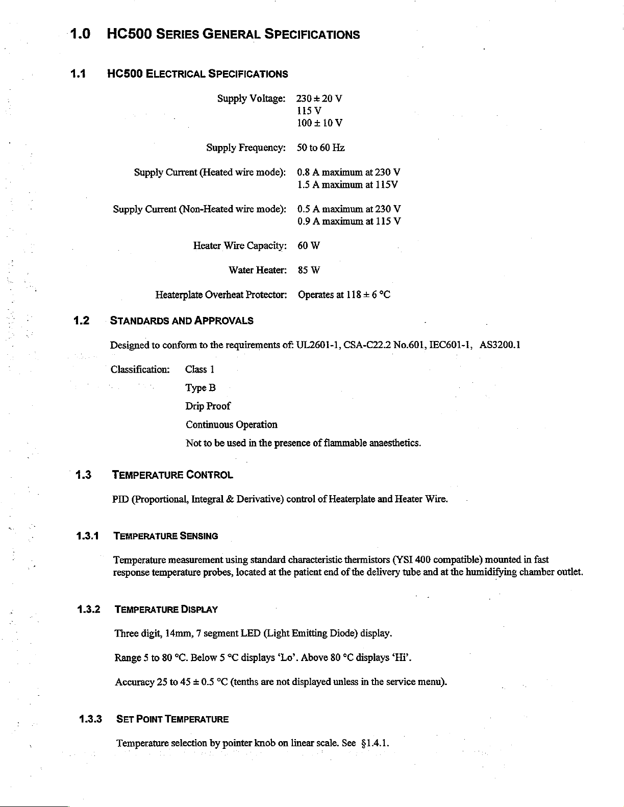
1.1
1.2
HC500
Supply
ELECTRICAL
Supply
Current
Current
Heaterplate
STANDARDS
Designed
to
conform
AND
Classification:
SPECIFICATIONS
Supply
Supply
(Heated
(Non-Heated
Heater
Wire
Overheat
APPROVALS
to
the
Class
1
Voltage:
Frequency:
wire
mode):
wire
mode):
Capacity:
Water
Heater:
Protector:
requirements
230+20V
115Y
100+10V
50
to
60
0.8 A maximum
1.5 A maximum
0.5 A maximum
0.9 A maximum
60
W
85
W
Operates
of:
UL2601-1,
Hz
at
118 + 6
CSA-C22.2
at
at
at
at
230
115V
230
115
°C
V
V
V
No.601,
IEC601-1,
AS3200.1
1.3
1.3.1
1.3.2
TEMPERATURE
PID
(Proportional,
TEMPERATURE
Temperature
response
TEMPERATURE
Three
Range 5 to
Accuracy
measurement
temperature
digit,
14mm, 7 segment
80
25
to
Type
B
Drip
Proof
Continuous
Not
to
be
used
Operation
in
CONTROL
Integral & Derivative)
SENSING
using
probes, located
DISPLAY
LED
°C.
Below 5 °C
45 + 0.5
°C
(tenths
displays
the
presence
control
standard
at
the
(Light
“Lo”.
are
not
of
flammable
of
Heaterplate
characteristic
patient
Emitting
Above
displayed
thermistors
end
of
the
Diode)
80
*C
unless
displays
anaesthetics.
and
Heater
(YSI
delivery
tube
display.
“Hi”.
in
the
service
Wire.
400
compatible)
and
at
menu).
mounted
the
humidifying
in
fast
chamber
outlet.
1.3.3
SET
POINT
TEMPERATURE
Temperature
selection
by
pointer
knob
on linear
scale.
See
§1.4.1.
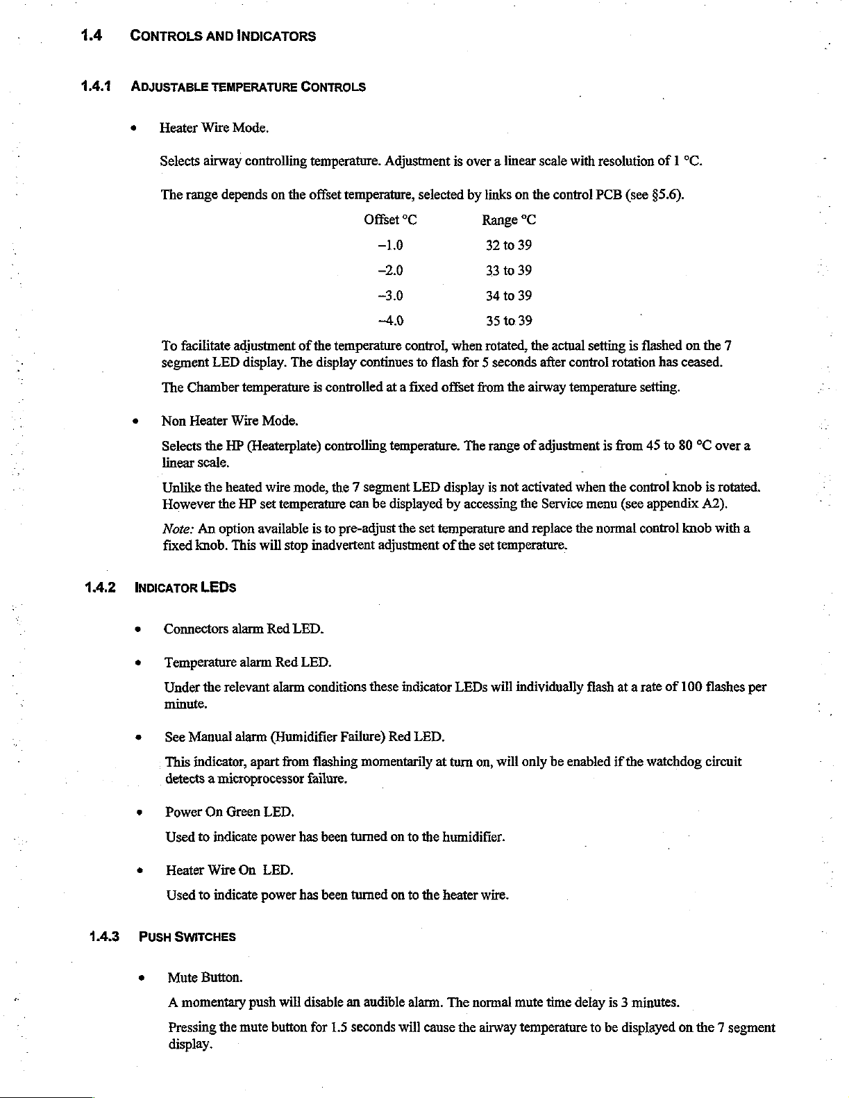
1.4
CONTROLS
AND
INDICATORS
1.4.1
ADJUSTABLE
Heater
Selects
The
range
To
facilitate
segment
The
Chamber
Non
Selects
linear
Unlike
However
TEMPERATURE CONTROLS
Wire
Mode.
airway
controlling
depends
adjustment
LED
display.
on
the
of
The
temperature
Heater
Wire
Mode.
the
HP
(Heaterplate)
scale.
the
heated
wire
mode,
the
HP
set
temperature
temperature.
offset
temperature,
Offset
-40
the
temperature
display
is
continues
controlled
controlling
the 7 segment
can
be
Adjustment
selected
°C
—1.0
—2.0
-3.0
control,
to
flash
at a fixed
temperature.
LED
displayed
is
over a linear
by
links
Range
32
33
34
35
when
rotated,
for 5 seconds
offset
from
The
range
display
by
is
accessing
on
the
°C
to
39
to
39
to
39
to
39
the
the
airway
of
not
activated
the
scale
with
control
actual
after
PCB
setting
control
temperature
adjustment
when
Service
menu
resolution
(see §5.6).
is
flashed
rotation
setting.
is
from
45
the
control
(see
appendix
of 1 °C.
on
has
ceased.
to
80
°C
knob
the
7
over
is
rotated.
A2).
a
142
Note:
An
option
fixed
knob.
This
INDICATOR
LEDs
Connectors
alarm
Temperature
the
Under
relevant
alarm
minute.
See
Manual
This
alarm
indicator,
apart
detects a microprocessor
Power
On
Green
Used
to
indicate
Heater
Wire
On
Used
to
indicate
available
will
Red
stop
LED.
Red
LED.
alarm
is
inadvertent
conditions
(Humidifier
from
flashing
failure.
LED.
power
has
LED.
power
has
to
pre-adjust
Failure)
momentarily
been
tumed
been
turned
the
set
adjustment
these
indicator
Red
LED.
on
to
the
on
to
the
temperature
of
the
set
temperature.
LEDs
will
at
turn
on,
will
humidifier.
heater
wire.
and
replace
the
individually
only
be
enabled
normal
flash
at a rate
if
control
the
watchdog
of
knob
100
with
a
flashes
per
circuit
1.4.3
PUSH
SWITCHES
Mute
Button.
A
momentary
Pressing
display.
the
push
mute
will
button
disable
for
1.5
an
audible
seconds
alarm.
will
The
cause
normal
the
airway
mute
time
temperature
delay
to
is 3
minutes.
be
displayed
on
the 7 segment
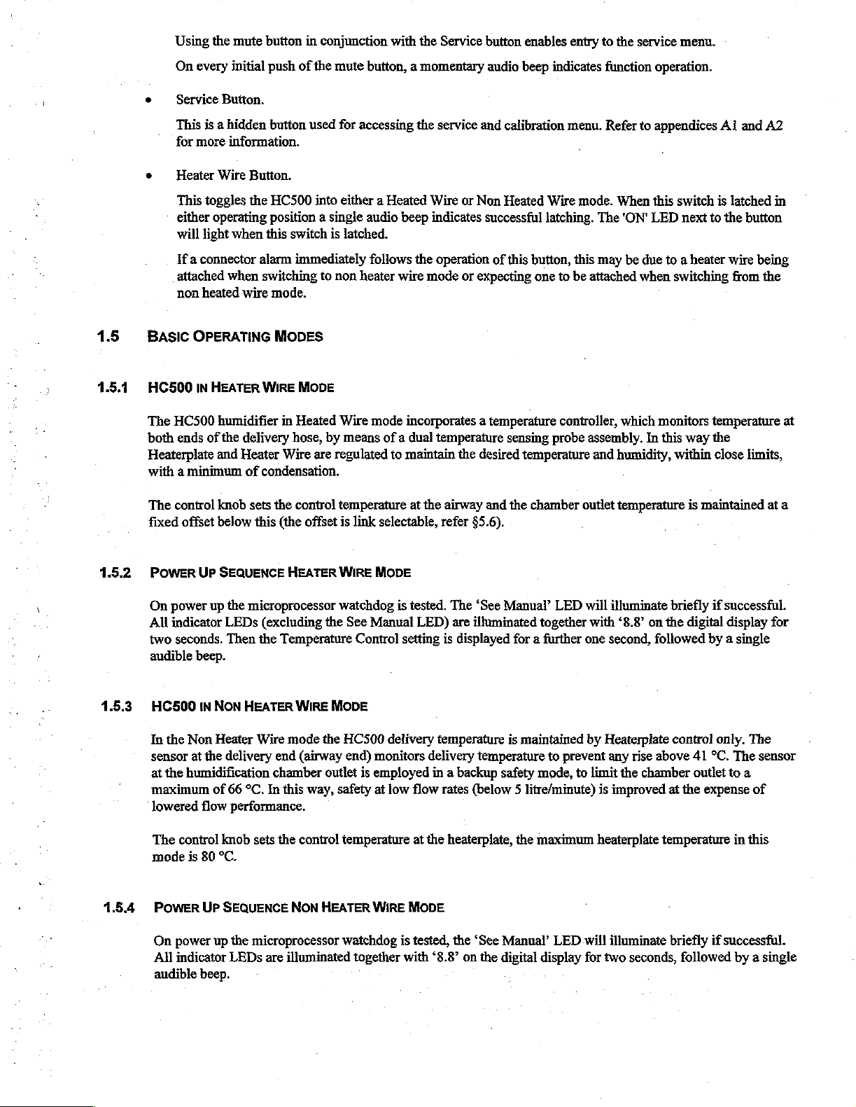
Using
the
mute
button
On
every
initial
e © Service Button.
This
is a
hidden
for
more
information.
+
Heater
Wire
Button.
This
toggles
either
will
light
the
operating
when
this
in
conjunction
push
of
the
mute
button
used
for
accessing
HC500
into
either a Heated
position a single
switch
is
latched.
with
the
Service
button, a momentary
the
service
Wire
or
Non
audio
beep
indicates
button
enables
audio
beep
and
calibration
Heated
successful
entry
to
indicates
function
menu.
Wire
mode.
latching.
The
the
Refer
When
'ON'
service
menu.
operation.
to
appendices
this
switch
LED
next
is
to
Ai
the
and
A2
latched
button
in
1.5
1.5.1
1.5.2
If a connector
attached
non
BASIC
HC500
The
HC500
both
ends
Heaterplate
when
heated
OPERATING
IN
HEATER
humidifier
of
the
and
with a minimum
The
control
fixed
Power
On
power
All
indicator
two
audible
knob
offset
below
Up
SEQUENCE
up
the
LEDs
seconds.
Then
beep.
alarm
immediately
switching
wire
mode.
MODES
WIRE
MODE
in
Heated
delivery
Heater
of
sets
microprocessor
hose,
Wire
are
condensation.
the
control
this
(the
offset
HEATER
(excluding
the
Temperature
to
non
heater
Wire
by
means
regulated
temperature
is
link
WIRE
watchdog
the
See
Control
follows
mode
the
operation
wire
mode
or
expecting
incorporates a temperature
of a dual
to
selectable,
temperature
maintain
at
the
airway
refer
the
desired
§5.6).
and
MODE
is
tested.
The
‘See
Manual
LED)
setting
is
are
illuminated
displayed
of
this
button,
one
sensing
temperature
the
chamber
Manual’
together
for a further
this
may
to
be
attached
controller,
probe
assembly.
and
outlet
LED
will
illuminate
with
one
second,
be
due
to a heater wire
when
switching
which
monitors
In
this
humidity,
temperature
“8.8”
on
the
within
briefly
followed
temperature
way
the
close
is
maintained
if
successful.
digital
display
by a single
being
from
limits,
the
at
for
at
a
1.5.3
1.5.4
HC500
In
sensor
at
maximum
:N
the
Non
at
the
humidification
lowered
The
control
mode
is
POWER
On power
All
indicator
audible
beep.
NON
HEATER
Heater
the
delivery
of
66
°C.
flow
performance.
knob
sets
80
°C.
UP
SEQUENCE
up
the
microprocessor
LEDs
WIRE
Wire
mode
end
(airway
chamber
In
this
the
control
NON
are
illuminated
MODE
the
HC500
outlet
way,
safety
temperature
HEATER
watchdog
delivery
end)
monitors
is
employed
at
low
WIRE
together
delivery
in a backup
flow
at
the
MODE
is
tested,
with
‘8.8’
temperature
rates
heaterplate,
the
on
is
maintained
temperature
safety
(below 5 litre/minute)
the
‘See
Manual’
the
digital
to
prevent
mode,
to
maximum
LED
display
by
Heaterplate
any
rise
limit
the
chamber
is
improved
heaterplate
will
illuminate
for
two
seconds,
control
above
at
41
outlet
the
expense
only.
°C.
temperature
briefly
if
followed
The
The
sensor
to
a
of
in
this
successful.
by a single
2.1.5
Power
A
buffered
to
frequency
switching.
this
LINE
sample
ground
source.
of
by
when
facilitating
The
INTERRUPT
the
power
Schmitt
the
trigger
diodes
ADC
supply
USf,
D13
the
generation
is
also
phase
frequency
and
fed
to
D16
are
of a real
synchronised
is
derived
to
the
RST7.5
not
conducting. The
time
with
from
interrupt
clock
the
the
power
and
also
line
frequency
transformer
of
U3.
Resistor
operating
software
enabling a zero
thus
eliminating
secondary
R68
pulls
determines
crossing
detector
any
via
R56
the
secondary
the
common
and
Q1,
winding
supply
for triac
error
from
2.1.6
2.1.7
41
°C
COMPARATOR
Operational
input
adjustable
low
above
D19,
pin
R55
amplifier
5 is
divider
an
and
temperature
A
watchdog
to
the
non
inverting
of a processor
HEATERPLATE
Thermistor
during
Under
HP
normal
certain
Programming
protection
transformer
mechanical
module.
should
primary
cut-out
connected
network
input
temperature
D20,
R61
greater
than
failure,
which
input
crash.
OVER
senses
operation,
operating
Control
the
and
must
U10c
U10c
is a
protection
directly
R33,
(via
VR4,
of
to
clamp
41
°C
causes
is a high
of
U10c.
TEMPERATURE
the
heaterplate
power
to
conditions
Options.)
electronic
thus
causes
be
manually
Also
control
circuit
connector
R32.
VR4
41
°C.
This
the
bases
of
both
heaters
output
from
This
also
temperature.
the
heaterplate
different
maximum
mounted
system
complete
reset
by
to
sense
J4-1)
is
set
low
output
switching
to
U5g,
ensures
Should
is
discontinued
on
the
fail.
This
shut
down
means
excessive
to
the
airway
during
calibration
(OVHT)
transistors
be
shut
down.
is
communicated
that
both heater
the
heaterplate
heaterplate
heaterplate
mechanical
of
the
humidifier
of
the
reset
delivery
temperature
thermistor.
to
ensure
is
fed
via
the
Q10
and
Q12.
via
isolating
control
circuits
exceed a preset
until
it
cools
temperatures
is a
mechanical
cut
out
is
should a serious
button
located
The
inverting
that
the
isolating
In
this
diode
are
below
this
can
be
selected.
thermal
connected
on
the
underside
rise.
The
input
output
diode
resistor
way,
an
D11
and
clamped
maximum
limiting
cut out
in
series
fault
non
inverting
goes
to
an
pin 7 of
UlOc
networks
airway
resistor
off
in
the
R31
event
temperature
temperature.
(See
§5.6,
which
will
give
with
the
power
develop.
of
The
the
heaterplate
is
2.1.8
WATCH
During
output
fed
this
which
or
should
humidifier
To
LED10,
POWER
A
protected
from
The
U12,
triac,
Doc
operation
port
to
the
charge
square
wave
drives
may
not
fail,
is
indicate
and
BOARD
bridge
rectifier
by a 1
the
voltage
heaterplate
which
and
with
U5B,G
the
PB7
of
U4
pump
be
the
trap
be
successful
and
is
unable
tumed
that
the
also
turns
(D13
Amp
doubling
is
switched
in
tum
C33,
processor
every
circuitry
interrupted
interrupt
is
16.6
C16,
for
input
depending
to
re-initialise,
on
by
deliberately
processor
fuse
off
to
has
the
display
D16)
(F1)
supplies
mounted
network
by a port
switches
form a snubber
triac
continually
or
20ms
D4,
monitored
(power
D5
and
any reason,
of
U3.
This
on
the
nature
it
fails
halting
failed,
the
high
I-C
U7
to
power
on
the
D17,
D18,
pin,
PC4,
Q11
(mounted
network
for
line
C15,
C15
will
high
trap
of
the
in a safe
program
output
blank
the digital
to
the 5 V
circuit
C25.
of
U4
on
on
the
both
the
for
correct
frequency
which
interrupt).
ensures
discharge
input
forces
fault.
The
mode.
The
execution
of
U5g
also
display.
regulator,
board.
The 5 V
the
control
heatsink).
triac
and
function.
through
that
This
This
square
pin
13
R3
giving a high
re-initialisation
purpose
and
Resistors
optoisolator.
of
watchdog
waiting
turns
on
Q7
mounted
negative
board
(HPC)
R57,
this
circuit
for
Q3
which
supply
R64
is
done
by
changing
wave
buffered
of
U5g
is
held
hard
output
of
the
processor
is
to
ensure
that
is
tested
every
initialisation
on
the
stabilised
and
controls
limit
lights
heat
sink.
the
via
the
humidifier
This
by
the
gate
the
state
by
USb
up.
Should
from
pin
12,
which
may
if
the
processor
time
the
the
watchdog.
fault
circuit
08,
is
derived
optoisolator
current
to
the
of
is
is
The
Heater
Wire
optoisolator
control
Heater
optoisolator’s
U13
then
the
HHS
circuit.
board
wire
during
to
U4.
signal
U11
(HHC).
sensing
LED
the
Resistor
circuit
(HHC)
which
in
R9
is
performed
by
R52
negative
R67
whether a heater wire
is
turn
is
and
C6
when
cycle
of
prevents
controlled
driven
are a snubber
by
optoisolator
triac
the
false
by
by
Q10.
Q9
is
on
22Vac
secondary.
triggering
is
connected
triac
Q9
Q10
is
network
U13
and
and
by
of
the
or
open
which
is
mounted
controlled
for
associated
R51
The
U13
circuit,
directly
the
heater
and
R52
output
of
phototransistor.
and
on
the
from
an
wire
triac.
components.
when
the
triac
the
optoisolator
The
whether
the
heat
sink.
output
Current
is
off.
Diode
(HHS)
software
heater
wire
Q9
is
port
of
is
limited
D21
connects
can
determine
fuse
switched
U4
on
the
through
protects
to
USd
F2
is
open
by
the
the
and
from
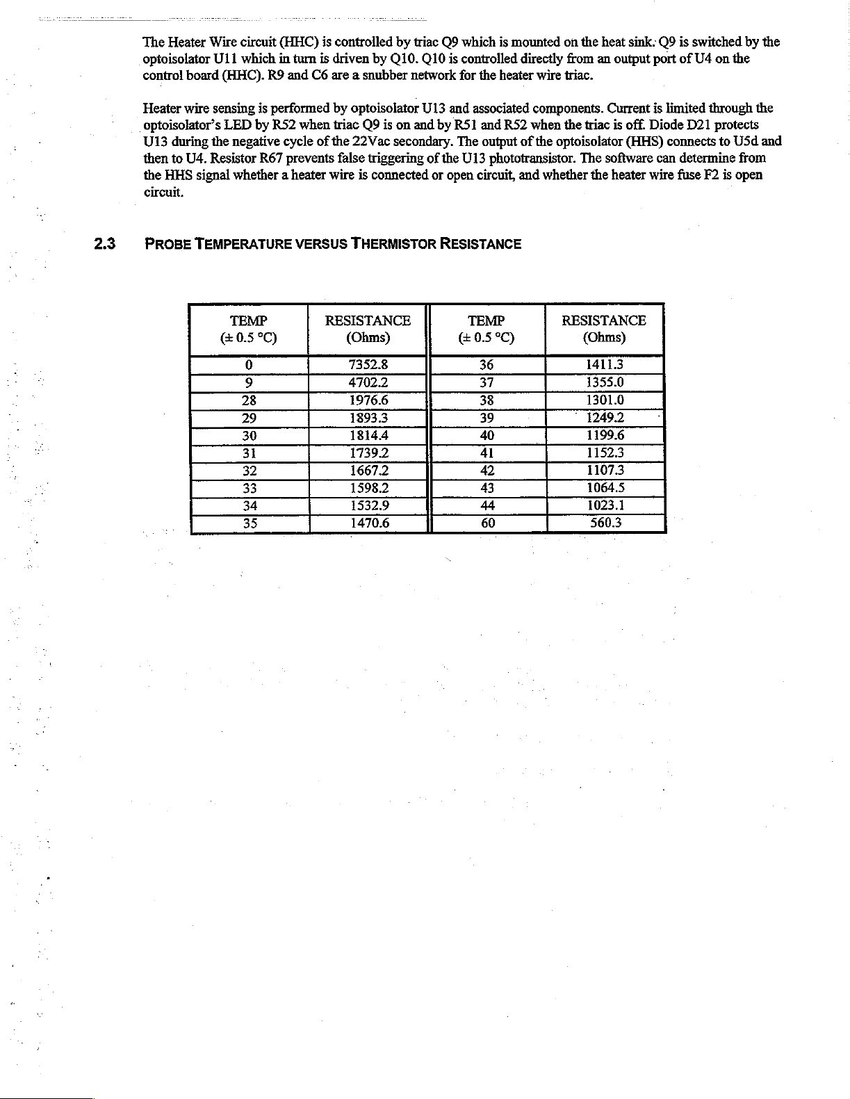
2.3
PROBE
TEMPERATURE
TEMP
(£0.5°C)
0
9
28
29
30
31
32
33
34
35
VERSUS
THERMISTOR
RESISTANCE
(Ohms)
73523
47022
1976.6
18933
18144
1739.2
1667.2
1598.2
1532.9
1470.6
RESISTANCE
TEMP
||
05°C)
36
37
38
39
40
41
44
42
43
60
RESISTANCE
(Ohms)
14113
1355.0
1301.0
712492
1199.6
11523
11073
1064.5
1023.1
5603
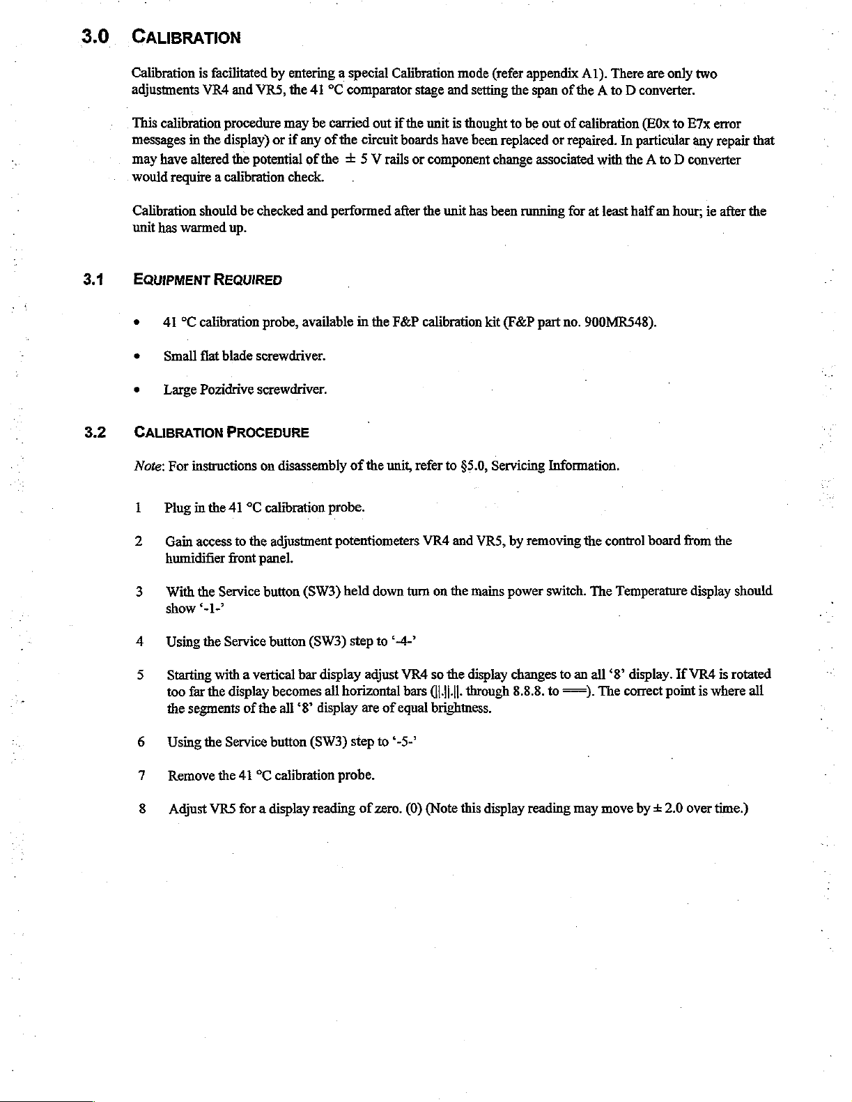
3.0
CALIBRATION
3.1
3.2
Calibration
adjustments
This
messages
may
would
Calibration
unit
EQuiPMENT
+
e
‧
is
facilitated
VR4
calibration
in
the
have
altered
require a calibration
should
has
warmed
REQUIRED
41
°C
calibration
Small
flat
Large
Pozidrive
CALIBRATION
Note:
For
instructions
by
and
VRS,
procedure
display)
the
potential
be
checked
or
up.
probe,
blade
screwdriver.
screwdriver.
PROCEDURE
on
disassembly
entering a special
the
41
°C
comparator
may
be
carried
if
any
of
of
the + 5 V rails
the
circuit
out
check.
and
performed
available
in
of
the
the
Calibration
stage
and
if
the
unit
is
boards
have
or
component
after the
F&P
unit,
unit has
calibration
refer
to
mode
(refer
setting
thought
been
change
been
kit
$5.0,
Servicing
appendix
the
span
to
be
out
replaced
associated
running
(F&P
part
Information.
A1).
There
are
of
the A to D converter.
of
calibration
or
repaired.
with
for
at
no.
900MR548).
(E0x
In
particular
the A to D converter
least
half
only
an
two
to
E7x
any
hour;
error
repair
ie
after
that
the
„=
Plug
2
Gain
humidifier
3
With
show
4
Using
5
Starting
too
the
6
Using
7
Remove
8
in
access
the
*-1-*
the
far
segments
the
Adjust
the
41
°C
calibration
to
the
adjustment
front
panel.
Service
button
Service
button
with a vertical
the
display
Service
the
VRS
becomes
of
the
all
button
41
°C
calibration
for a display
probe.
potentiometers
(SW3)
held
(SW3)
step
bar
display
all
horizontal
‘8’
display
(SW3)
step
probe.
reading
down
to
“-4-*
adjust
VR4
bars
are
of
equal
to
*-5-º
of zero.
VR4
and
turn on
the
so
the
([|.|j.||.
brightness.
(0)
(Note
VRS,
mains
display
through
this
display
by
removing
power
switch.
changes
8.8.8.
to
reading
to
an
==).
may
the
control
The
Temperature
all
“8”
The
correct
move
board
display.
If
point
by + 2.0
from
the
display
VR4
is
is
where
over
time.)
should
rotated
all
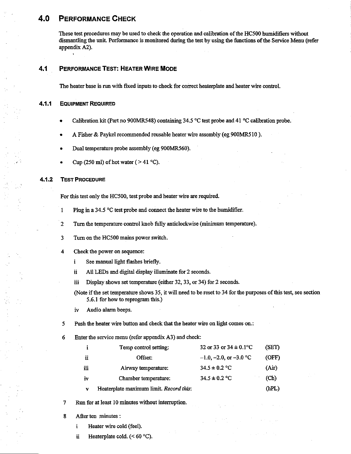
4.0
PERFORMANCE
These
test
procedures
dismantling
appendix
the
A2).
may
unit.
Performance
CHECK
be
used
to
check
is
monitored
the
operation
during
the
and
test
calibration
by
using
the
of
the
HC500
functions
humidifiers
of
the
Service
without
Menu
(refer
4.1
4.11
4.1.2
PERFORMANCE
The
heater
base
EQUIPMENT
Calibration
A Fisher
9
Dual
TEST
For
this
—
REQUIRED
temperature
Cup
(250 ml)
PROCEDURE
test
only
Plug
in a 34.5
Turn
the
TEST:
is
run
kit
& Paykel
HEATER
with
(Part
no
recommended
probe
of hot
water
the
HC500,
°C
test
temperature
WIRE
fixed
inputs
900MR548)
assembly
(>
41
test
probe
probe
and
control
knob
MODE
to
check
containing
reusable
(eg
900MR560).
°C).
and
heater
connect
fully
for
correct
heaterplate
34.5
°C
test
heater wire
wire
the
heater
anticlockwise
assembly
are
required.
wire
(minimum
probe
to
the
humidifier.
and heater
and
(eg
900MRS510
41
°C
calibration
wire
temperature).
control.
probe.
).
Turn
Check
i
ii
iii
(Note
iv
Push
Enter
ii
iii
iv
Run
on the
HC500
the
power
See
manual
All
LEDs
Display
if
the
5.6.1
for
Audio
the
heater
the
service
i
v
Heaterplate
for
at
least
mains
on
sequence:
light
and
digital
shows
set
set
temperature
how
to
reprogram
alarm
beeps.
wire
button
menu
Temp
Airway
Chamber
10
minutes
power
flashes
briefly.
display
temperature
shows
and
(refer
appendix
control
Offset:
temperature:
temperature:
maximum
without
switch.
illuminate
(either
32, 33,
35,
it
will
this.)
check
that
the
A3)
setting:
limit.
Record
interruption.
for 2 seconds.
or
34)
need
to
be reset
heater
wire
and check:
32
-1.0,
34.5 + 0.2
34.5 + 0.2
this:
for 2 seconds.
to
34
for
the
on
light
comes
or
33
or
34 + 0.1°C
-2.0,
or
-3.0
°C
°C
purposes
on.:
(SET)
°C
(OFF)
(Air)
of
this
(Ch)
(HPL)
test,
see
section
After
ten
i
Heater
ii
Heaterplate
minutes
wire
:
cold
(feel).
cold.
(<
60
°C).
Turn
10
Enter
i
11
Run
12
After
i
ii
13
Disconnect
14
Press
15
Reconnect
16
Disconnect
17
Reconnect
18
Place
the
temperature
the
service
Temp
control
for
at
least 10
ten
minutes:
Check
in
the
heaterplate
Heater
Wire
the
the
MUTE
the
heater
the
the
temperature
the
airway
control
menu
(refer
setting:
minutes
Service
maximum
hot
heater
button
temperature
probe
without
menu
noted
(feel).
wire
and
and
wire
and
probe
probe
end
sensor
knob
fully
appendix
interruption.
that
above
check
check
that
check
and
and
into a cup
clockwise.
A3)
and
the
heaterplate
(6v).
Note
that
the
Connectors
the
audio
that
the
Connectors
check
again
check
that
of
check:
39
°C
temperature
the
default
alarm
is
for
the
the
Connectors
hot
water
(hP)
setting
light
flashes,
silenced.
LED
stops
Connectors
alarm
(>
41
°C).
(SET)
is
approximately
is
100
°C.
and
the
audio alarm
flashing.
and
audio
stops.
the
alarms.
same
as
the
commences.
4.2
4.2.1
19
Check
that
show
the
Note:
The
since
they
20
Remove
below
41
21
Go
straight
PERFORMANCE
This
test
checks
EQUIPMENT
Calibration
A Fisher & Paykel
Fisher & Paykel
the
Temperature
current
HC500
are
due
the
temperature
°C
check
to
the
TEST:
that
the
REQUIRED
kit
(Part
light
airway
temperature
may
indicate
to
the
that
the
non
heater
NON
heaterplate
no
900MR548)
dual
humidification
spurious
rapid
change
probe
from
Temperature
wire
HEATER
is
temperature
flashes
and
above
‘EP4’
in
temperature.
the
cup and
light
mode
test.
WIRE
controlled
containing
probe
assembly,
chamber
(eg
the
41
°C.
or
goes
MODE
to
the
HC335)
HC500
similar
watch
off
correct
34.5
°C
audio
alarm
messages
the
temperature
and
the
Airway
temperature,
test
probe
eg
900MR560.
filled
to
the
begins.
on
the
fall.
display
selected
and
41
maximum
The
temperature
display.
When
These
the
goes
by
the
°C
calibration
water
level.
display
can
be
temperature
blank.
“Temp
Control’
probe
should
ignored
drops
knob.
4.2.2
Cup
TEST
PROCEDURE
(Ensure
1
Fill
2
Plug
3
Turn
(250
that
the
in
the
ml)
of
the
heater
chamber
the
34.5
Temp
hot
water
wire
is
to
the
maximum
°C
test
Control
(>
turned
probe.
knob
41
°C).
off
i.e.-
water
fully
clockwise.
heater
ON
level
and
Enter
LED
slide
it
the
is
off)
onto
the
Service
heaterplate.
Menu
and
check:
4
This
i
Temperature
Run
for a further
is
the
end
of
the
Control
30
setting:
minutes,
performance
then
check
check,
80.0
again
record
the
+0.2
the
test
°С
heaterplate
results
(ЗЕТ)
on
the
temperature,
maintenance
it
should
chart , see
now
appendix
read
80 + 1
B2.
°C.
4.3
431
4.3.2
DUAL
PROBE
This
test
is
recommended
as
to
the
accuracy
both
probes
(chamber
verification
manner,
depending
thermometer
EQUIPMENT
‧
e
e
‧
TEST
of
any
probes
on
REQUIRED
Dual
Temperature
Mercury
Cup
(250
Heater
wire
PROCEDURE
reading
TEMPERATURE
to
be
performed
of
the
temperature
and
airway)
temperature,
exhibiting a temperature
the
accuracy
filled
ml)
of
if
using
if
of
would
also
probe
glass
thermometer.
warm
water ( 20
HC500
so
desired.
the
be
to
be
TEST
probe. This
firstly
to
In
mercury
suspect.
tested.
to
in
heater
on
temperature
test
one
another,
the
first
difference
in
the
glass
40
°C).
wire
mode.
probes
allows
the
and
secondly
case,
assuming
of
more
thermometer
at
least
every
operator
than
to
to a glass
that
both
0.7
°C
any
probes
six
months,
compare
thermometer
probes
would
be
not
agreeing
or
the
temperature
have
not
suspect.
within + 1.5
if
there
for
absolute
failed
in a similar
In
the
is
any
doubt
readings
second
°C
of
case,
of
the
1 . Plug
connected.
2
Turn
3
Insert
40°C.
with a rubber
4
Place
5
Enter
alternate
points
6
Check
not
7
Check
the
dual
on
the
both
temperature
As
temperature
the
thermometer
the
Service
between
showing).
the
temperature
exceed
that
probe
HC500
band
menu
the
0.7 °C.
the
chamber
into
the
mains
power.
sensor
gradients
during
this
in
the
(refer
airway
difference
and
HC500
probes
can
test.
water
appendix
and
chamber
airway
Humidifier.
into a container
be
quite
large
alongside
between
probes
the
A2)
and
temperatures
chamber
read
If in
Heater
filled
it
is
recommended
probes
select
and
within
Wire
mode,
with
water
and
allow a minute
‘CP’
(compare
(chamber
temperature
airway probes
1.5
°C
of
the
ensure a heater wire
at a temperature
that
the
two
probes
for the
temperatures
probes)
mercury
option.
as
indicated
thermometer.
is
displayed
by
between
be
held
The
display
with
the
display.
assembly
20
and
together
to
stabilise.
will
all
decimal
It
should
is

5.0
SERVICING
This
section
two
separate
be
replaced
INFORMATION
provides
circuit
by a new
information
boards,
board. See
the
for
power
§3
regarding
servicing
board
the
and
calibration
HC500
control
Humidifier.
board.
In
the
after
repair.
The
electronic
event
of a board
circuitry
developing a fault,
is
contained
it
on
may
5.1
5.1.1
5.1.2
PRINTED
CIRCUIT
CONTROL PCB
The
front
panel
from
the
rear
connectors
down
release
When
POWER
Separate
Power
The
edge
lifted
harness
and
the
three
the
the
latches
PCB
the
PCB
power
of
the
slightly
connectors
cut the
(i
board.
case
and
board
board
cable
and
heaterplate
of
the
humidifier
and
J2)
plastic
This
release,
front
Control
and
and
to
clear
which
tie
BOARD
REMOVAL
assembly
body.
disconnected
retaining
is
from
heat
moving
the
holding
latches
facilitated
the
board
the
humidifier
PCB
(J1
sink
assembly
the
lower
retaining
can
now
the
The
from
protruding
if a slight
will
and
J2).
board
be
detached.
mains
cord
is
separated
front
panel
the
rear
upward
pop
up
leaving
body
Cut
the
can
now
forward
guides
in
place.
from
assembly
of
the
through
finger
the
and
disconnect
cable
tie
be
removed
slightly
and
moved
Before
removing
the
humidifier
can
control
the
board.
board
pressure
push-on
holding
by
to
disengage
further
now
be
If
the
can
be
is
maintained
control
the
two
ribbon
the
heaterplate and
flexing
from
forward
the
PCB,
body
moved
front
moved
knob
the
case
the
to
unscrew
by
removing
aside
panel
in
on
behind
cable
sides
case.
gain
access
the 4 fixing
and
the
is
now
the
appropriate
either
edge
in
the
connectors
chassis
The
the
away
board
to
mains
wires
from
the
cord
screws
two
ribbon
positioned
direction
of
the
board.
front
panel.
joining
the
together.
the
chamber
should
now
various
wiring
connections
cable
face
to
be
5.2
5.3
HEATERPLATE
To
reset
the
over
(through a smali
To
replace
μα
2
3
4
5
6
When
heaterplate
FAULT
the
heaterplate:
Separate
Unclip
Unplug
Unscrewthe
Unplug
assembly
Detach
the
the
the
the
the
replacing
spring
LOCATION
is
temperature
hole
under
the
case
front
from
Power
PCB
from
heaterplate
earth
ribbon
now
heaterplate
the
heaterplate,
loading).
wires
screw
cables
separate
from
protector,
separate
heaterplate
the
humidifier
the
case
from
the
on
the
chassis
from
the
Power
from
the
the
case
ensure
that
in
body
Power
case
front
the
for
PCB
body.
the
the
case
front
body.
(see
$5.1.2).
PCB
the
heaterplate
to
by
removing
three
springs
front
from
panel
case
(connectors
earth
the
Control
the
three
are
in
the
case
body,
assembly).
J3
and
17).
wire.
PCB
(connectors
screws
place
on
the
then
push
J1
and
which
secure
heaterplate
the
reset
32).
The
it
to
the
fixing
button
front
case
legs
case
front.
(check
the
If
neither
transformer
checked
the
by
digital
display
primary,
depressing
check
the
nor any
that
the
red
reset
of
the
front
mechanical
button
(see
panel
LEDs
overheat
§5.2).
are
on
protector
and
on
the
no
power
heaterplate
appears
has
not
to
be
cut
reaching
out.
This
the
may
be

Determine
display
humidifier
presence
ms
clock
fault
if
is
blank,
fault
of a 33
is
elsewhere.
all
power
supplies
check
the
LED
indicator
to
40
ms
period
present a fault
in
are
operational
watchdog
and
isolate
square
the
watchdog
output
the
wave
circuitry
and
(pin
heater
at
PB7
all
fuses
12
U5g).
circuits,
(pin 1 USb).
is
indicated
are intact.
A high
output
but not
If
but
If
the
power
here
will
necessarily
the
watchdog
if
port
PB7
is
supplies
blank
stop
the
output
not
changing
are
OK
the
display,
processor.
is
high
and
state
but
the
tum
on
Check
the
33
there
the
for the
to
40
is
a

54
HC500
CIRCUIT
ul
084
LAYOUT
109911198
qunoo
pees
SHA
|
BLOCK
ХПИ
16400
Авар
046
«
=
(dus
Fume
LE
ОЛ
|
Moro
ejes
ses
dues
10183006
DIAGRAM
uogeusosu!
Áejdsip
了
ΝΟΙΜΘΛΟ
Jejunos
=
=
(e)
озеру!
sazı
x=
8
J0sseooldojol
山
99
99
191
198
=
JIMMGIBSU
epou
vonna
On
2
一
一
让
|
(ol
Wodd3sosseooid)
90Id
IOUO9
e
81198
。
dvdl
4
4
sup
.
BOT
qnd
XNW
ouez
BujSsoso
NI
님
Bopyopem
sou
1
wi
ae
UniOA
mere
pan
ay
mm
本
o
Bep
by
seul
lolluoo
=
16189U
и
N
JOjeJeduioo
NS
euuayeay
ор
0
OYAZE
ejerdiajeeu
22
ooo
sles
o
quiod
Bop
PUA
Ly
jnolp
ohuoo
9JIAU9jBSU
nolo
lonuoo
aleldisleay
jauuedi
시
0009
nono
©
69096
vo
È
9
Bep
“vo
09
TEA
dual
125
>
Y
dgdUdBlO
"sy
1.
D
©
©

5.4
COMPONENT
LAYOUT - REVISION H PCB
=
>
iy
È
|=
0
|
5
N
г
o
<
©
~
+
2
gee
に
κο
3
é
med."
=
ZA
。
ノ
4/77
mors
see
s
ερ
μάς
KDM)
S
F
Genre,
s
A
ale
5
seas:
a
5
O
Selle
E
“peo
ee
22924;
3
Z,
Len
+
39Υ110Λλ
“E
яя
ses)
E
>
ΗΟΙΗ
ΝΟΗΠΥΟ
©
ン
ee
ee:
~
e
s
o
lea
‘less
ele
È
è
02
IN
ge 33
3,
Fe
Elam
C
SE
008
U
©
8
B
8
호
U
O
3
see,
cds
.
Rice
Elles!
GIVE
È
*
..
tld
(o)
оо
Е
CO
aft
see
μή
ae
후
fica
し
ze
Sİ
ee
:
2.
e

5.5
COMPONENT
LAYOUT - REVISION J PCB
e
|
a
è
|
>
T
ii
~
oo
S
©
o
M)
z
Zem
U
SH
el
ae
=,
©
E
He
UF
i
Het
Е
EPA
ewe

5.6
LINK
PAD
LOCATIONS
FOR
PROGRAMMING
CONTROL
OPTIONS - REVISION H AND J PCB
Link
Pads ® >
Control
(viewed
soldered
Board
from
side)
MİN
e
Si
SE,
k
se
pre
o
Location
E
leje
el
+
...
Pads
for
Programming
of
Link
Control Options
5.6.1
PROGRAMMING
The
following
x = don't
=
0 = no
LI
1
1 1
0
0 0
x x
x
x x
x
x x
x
The
offset.
care.
link.
link.
12
0
1
x
x
x
factory
default
CONTROL
options
5
K
X
κ
KRK
の
ビー
メー
AA
A
settings
can
pe
mx
Mx
MM
HM
OPTIONS
be
enabled
re a E
κ
K
K
K
K
K
r
r
© ©
are
for
by
a
ὃν
KM
에
에
ON
NONO
DO
mi
the
joining
50
80
90
100
ISO
Gliding
—1.0
—2.0
~3.0
—4.0
100
*C
the
pads
°C
maximum
°C
maximum
°C
maximum
°C
maximum
draft
standard
tone
°C
temperature
°C
temperature
°C
temperature
°C
temperature
maximum
on
the
control
temperature
temperature
temperature
temperature
audio
alarm.
audio
alarm.
offset.(32
offset.(33
offset
offset.(35
heaterplate,
PCB
as
shown
Heaterplate.
Heaterplate.
Heaterplate.
Heaterplate
to
39
°C
to
39
°C
(factory
ISO
setting).(34
to
39
°C
audio
(factory
range)
range)
range)
alarm
in
$5.6.
settng).
to
39
and —3.0
°C
range)
°C
temperature


I T I I I
sese
in
Me
E)
o
ven
we
LI
JJMAV
em
3HV9HLTV3H
R
H3HSIJ
ET
a
"NGIuJ30
»
OBRAS
E
1
z
133HS
11
NOISIAIG
SaINOSI9313
uva
33HS
は
ua
com
ино
=
피
“nt
обо
и
e
и
smuo
бло
«а
al
300 100
soul
ЗИ
Mo
oo
=
no;
da
40
238NON
616
040
9NMKYSG
5y0
saves
costa
VETO
ue
emas,
va
a
ae
배게:
©
Y
mare
E
=
σα
TOULNOI
I
H
NOISIAZY
=
-
SNYSDVIC
I
LINOUID
219
wi
EHS
Tt
OL
EN
om
Drea
Cain
aon
ми
235),
arme
OO
CENTER)
SRI
E
AB»
üne
vas
sean
sa
terem
am
Jo
waoe
reni
vedono
sens
で
LZE
NO
O3NWLNOD
—
404
TOBINDO
e
CUTE
TA
TENENTE
E
E
0
FT
==

=
5
a
OU
WERE
门
s
Β
e
-
e
57
to
su
CIRCUIT
DIAGRAMS
-
REVISION
H
POWER
PCB
CE
TONA
A
ENİ
ANA
SUS
FISHER
HEALTHCARE
&
PAYKEL
DIVISION
f=
z
b
mue
em,
[ec]
RA
POWER
P.C.B.
sage
Dia
vicia
πιο
|
ou:
te
em
VET
E
mom
Ys
se
AME
be
qo
mu
ef
|
a
em
ea
ΕΞ]
aroma
seres
3
LT
At
ο
зу
па
№
Steaua
E
serou
pra
j
=
“as
tono
xa
tr
2
A
İron
parer
dia,
>
‘боты
De]
CE
©
———O
шт
=
AL
pm
ovino
suoi
o
=>
ama
—
b
5
A
Yar
D
qe
re)
ima
i
se
3-1
ен
vam
・
ve
LE
rt
matt
str

fe
>
van
ones
MAYA
erin
a
©
en.
τσ
δν
%
YIHSIJ
017
NOISIAIO
9040810373
=
“reto
3UVOHLIVIH
73440
“o
Datura
03454
sE
Sa
FE
|
aus
[in
=
es
Fano
D/K
S
VY
IT
Soa
TE
E
yere
‘oe
“SHOES
DESİ
mame
E
Od
TOXLNOD
f
NOISIASY
-
SIAVHDVIO
LINIUIO
gs
©
1938
1
Ur
oL
sm
9
anziana
m
mo
1009
asa
애
no
sho
une
"Z
133HS
NO
dANNILNOO
=
694
TOVINOO
51013309
E
E
Н
EE
a
EE
Е
ES
de
pl
NA
EREC
ETO
AO
OV
IE
RER
E

το
42
SHEET
1
H
5.8
ro su
CIRCUIT
DIAGRAMS
-
REVISION
J
POWER
PCB
A
ER
τς
TEE
AR
PE
ri
MM
sou
043
040
319
SHEET
ος
SER
2
2
dE
aos
POWER
PCB,
προς
Çam
ESER
(HEALTHCARE
&
PAYKEL
DIVISION
dro
"7
or
ка
зат
а
a
|
Pa
2990
ELL
rom
mur
—]
i
4
233
μη
o
mm
i
||
:
veal)
si
sare
oca
ay
5
m
ο
mem
orna
sea
О
ο
(
‘LT
Άνω
위시
5011
0
i
i
i
ae
Tusa
deb
we
-o
b
nos
or
mì
>
:
i
se
#5
a
gi
ane
tos
>
STAR
sa
ni
PORT
ον
μα
i
pom
i
i
e
EE)
18.
Aero
25-2
y
pa
seen
re
soa
;
:
.

5.9
ELECTRICAL
The
electrical
diagrams
Note:
The
.
Control
PARTS
LIST
components
and
Power
listed
below
PCB
are
referenced
Assemblies
listed
below
in
accordance
are
with
parts
for
the
component
layout
revision H and J PCBs.
and
the
circuit
5.9.1
CONTROL
C1,
C3,
D1,
D2, D3, D4,
D6,
BOARD
COMPONENTS
Reference
C4, C5,
cio,
C9,
ci
C2
C12,C13
C14,
C15,
C16
C17
C18,C19,C20
C22,C23
C21,
C24
D5,
D7, D8,
D0,
D11,
D9,
D12
Description
PCB
Upgrade
operating
PCB
Eprom
Cap.
Cap.Mylar
Cap.
Cap.
Cap.
Cap.
Cap.
Cap.
Diode
manual
Assembly
Programmed
Ceramic
100nmF
Ceramic
Elec.
10
Ceramic 1 nF
Ceramic
Mylar
10
Ceramic
1N4l48
kit-Control
and
HC500
100
nF
22
pF
pF
25
22
nF
nF
50
470
pF
..ononocconnnoranionsonnecnernrncs
swing
Control
HC500
50
50
Ve
50
V...
V.
50
V
50
V..
50
(Contains
tag)
Version
V.
V.
V.....
PCB,
1.0..
front
merce
fascia,
Part
Number
043040919
043041056
362040084
312040153
316040085
..
312040130
..
311040663
«
312040107
..
312040116
316040084
..
312040118
361040155
DSPI,
DSP2,
NA,
LED1,LED2
LED6, LED8,
QE,
Q2,
Q3,
R1,
R2,
R3,
R14,
R26,
R28,
R36,
R39, R41,
R10, R33,
R19,
DSP3
RA
LED10
Q4,
Q13
RS,
R6,
R31,
R43
R4 Resistor
R7,R13
R8_
R65,R70
RII
RI2
815
R16
R17
及
18
R24,R69
R20
Display
14
LED
LED
Transistor
Resistor
pin
ribbon
green
red...
LED
current
inner
BC547B
10k
DIL
Resistor
Resistor
Resistor
Resistor
Resistor
Resistor
Resistor
Resistor
Resistor
Resistor
Resistor
4k7
27k
22k
180R
6k8
9k09
560R
1k5
4k7
2k2
412R
(HDSP5301
connector
orLLA6760).............
socket...
rein
0.25 W 3%.
Resistor
einen
pack
0.25 W 5%...
0.25 W 5%...
0.25 W 5%...
0.25 W 5%.
0.25 W 5%
0.25 W 1%
0.25 W 0.5%
0.25 W 0.5%
0.25 W 0.5%
0.25 W 5%
0.25 W 0.5%
7/27k
Metal
Metal
Metal
Metal
Metal
een
ns
999860001
341040357
361040329
neon
onen
onen
361040327
vonné
361040159
325040284
3W...occocionameseonssicmenes
8
Film.
Film.
Film....
Film.
Film...
seerne
325046010
...
325040287
…
325040319
…
325040318
...
325040309
....
325040335
....
325040145
«
325040135
es
....
325040137
....
325040138
....
325040282
325040152

R21,
R22,
R25,
R23,
R35,
R32,
R37,
SW3,
R27,
R29
R40
R30
R63
R34
R38
R42
SW4
SWS
Resistor
Resistor
Resistor
Resistor
Resistor
Resistor
Resistor
Push
Heater
820R
220k
22R
2k7
switch...
Wire
0.25 W 0.5%
100k
0.25 W 1%
0.25 W 1%
15k
0.25 W 5%
180k
0.25 W 1%
0.25 W 1%
0.25 W 5%
switch...
Metal
Metal
Metal
Metal
Metal
Film...
Film
.... ....
Film
.....
Film
Film...
325040136
325040139
ve.
325040134
....
325040317
...
325040125
..
325040133
999012720
349040094
…
349040099
SPKI
uz
U3
U4
US
U6,
US
U7
U9
U10
Audio
Transducer
IC
Octal
Latch
IC
Micro-Processor
IC
Ram
VO
IC
Hex
inverter
IC 8 Channel
IC
Display
IC
3x2
Channel
IC
Quad
Operation
10kPreset
5kPotentiometer...........
10k
Preset
Multiturn......
50k
Preset
rennes
Crystal644
Spacer
Service
Spacer,
Heater
CB-12KP........................
74LS373
8085
A-Z.
Timer
81C55
74HC14
Mux.
Driver
Mux.
MHZ
Button
Wire
CD4051B.
MM5451N
CD4053B....
Amplifier
PCB
Switch
TL074.
....
....
ue
oeeoeeaeoesen
ne
426040015
once
999610004
ve
999630012
...
363040415
.…
363040232
…
363040125
....
363040126
.
999610003
…
363040124
327041561
„
327041562
327041565
327041563
ner
999820001
693040701
693040522

5.9.2
POWER
BOARD
COMPONENTS
D13,
C6,
D14,
019,
06,
Reference
C8,
C32
C7,
C33
C25,
C27
C26
C28,
C29
030,
031
D15,D16,
217,
018
020,
D21
Fi
F2
F3,
F4
F3,
F4
Q10,
Q12
Q5
Q7
Q8
09,011
Description
PCB
Assembly
Cap.
MKT.
Cap.
Poly
Cap.
Elec.
Cap.
Elec.
Cap.
Elec.
Cap.
Ceramic
Diode
IN4002................riirrirnne
Diode
1N4148...,...sssesssssssnesssesssesessnesscnesnsssesenreneesesstsnsesenenanene
Fuse
fast
acting 1 Amp
Fuse
fast
acting 4 Amp
Fuse
fast
acting
Fuse
fast
acting 2 Amp
Transistor
Transistor
IC 5 Volt
IC 5 Volt
Triac
Q4004L3
Power.
100
nF
100
nF
250
470
pF
25
1000
uF
10
pF
25
22
nF
1.5
BC547B
BC557B
Positive
Negative
Regulator
or
BTA
100
V...
V...
V..
25
V.....
V
50
Vi...
(20 * 5
(20
x 5
Amp
(20
(20
x 5
..
..
7805.
Regulator
08-600
mm)...
mm)
x 5
mm)
mm)
79105.
cirie ieri
rss
for
230
for
115
Part
Number
.
043040637
..
311040028
…
316040073
....
999234710
…
999231020
...
311040663
.
312040116
nienecreecenreneecszeceniene
V.
V......................
361040163
361040155
999830001
...
999830017
…
999830008
999830009
...
361040159
.
361040156
.
999600003
.
363040146
.
999550011
911,
R44, R46,
R54,
R48,
R58,
R60,
R45,
R55,
912
013
R50,
R64,
R66
R61
R47
R49
R53,
R59
R56
R57
R51,
R52
R64
R67
R68
R9
IC
Optocoupler
IC
Optocoupler
Resistor
Resistor
Resistor
Resistor
Resistor
Resistor
Resistor
Resistor
Resistor
Resistor
Resistor
Resistor
Fuse
18R
10k
2k7
22k
120R
270R
12k
180R
3k3
220R
1M
100K
clips.........
MOC3022
CNY
0.25 W 5%...
0.25 W 5%
0.25 W 5%...
0.25 W 3%...
0.25 W 5%..
0.25 W 5%..
0.25 W 5%
0.25 W 5%..
0.25
W5%
0.25 W 5%..
0.25 W 5%
0.25 W 5%.....................
a.e
MOC30230r
I7-Bonococinnanacnonoroconeorenencinocarnonoonconiearicisacos
nn
итнизивьитьииоливиинивотунивошонипопивонолиия
K3022PG
ner
rm
...................
kasser
errar
367060001
363040045
325040366
325040284
999012720
νκτοωνε
325040318
..
325046034
..
325040294
・
325040289
.
325040309
…
325040303
..
325040296
.
325052305
325040139
999840001

5.10
MECHANICAL
Refer
to
the
PARTS
exploded
LIST
diagram ( $5.10.1).
Reference
11
12
13
14
15
16
17
18
19
20
21
22
23
24
25
26
27
Description
1
Heaterplate
Heaterplate
Heaterplate
Chamber
Chamber
Chamber
Chamber
Spring
Guard
BW
Gasket
La
PCB
Où
O
3
00
Assembly
PCB
Assembly
Case
Front
Probe
Case
Door
Switch
PCB
Assembly
Case
Foot..........
Case
Door
Mains
Mains
Mains
Mains
Mains
Mains
Mains
Mains
Screw
Case
Воду
Washer
Nut
M6
Bracket
Screw
Screw
Nut
M4
Bracket
Screw
Transformer
Transformer
Transformer
Tape
28
Screw
29
Clamp
30
Clamp
Insulator
31
Washer
32
Screw
33
Lug
Earth.....
Screw
34
Washer
35
Harness
36
Socket
37
Probe
38
Assembly
Assembly
Assembly
Clamp
Clamp
Clamp
Clamp
Mounting
Chamber
85 W 100
85 W 115
85 W 230
Kit
Blank ( includes
Kit
French
Kit
German
Kit
English
Kit..
Clamp...........
Kit
Socket
HC500
HC500
Specify:
Cap.
Control..
Control
‘Case
Right...
Harness
Assembly..
HC500
Power
Left.
Cord
UL
USA
Hosp
Cord
Australian
Cord
No
Cord
French
Cord
Danish
Cord
UK
Cord
Schuko
Cord
Schuko
#8 x 1/2"
Kit
Specify:
M6
Wavy
Nyloc
ZPS..
Transformer
M4 x 8
Pan
M4 x 50
Nyloc
ZPS..
Mounting
M6 x 25
Assembly
Assembly
Assembly
Foam
Adhesive 3 mm x 10
M4 x 14
Cord
Small...
Cord
Large...
Mains
M6
Ext
M6 x 16
M3
x
Lock
M4
J10-Hose..............
Heater
Wire
Socket
Harness
Clear
Plug....................
230 V No
Plug
230
Plug
230 V Fused
Plug
230 V Shoelace
Plug
230 V Earth
Pan
Phil
TY25
‘Case
...
..
Phil
ZP
Pan
Phil
ZP..
30
mm
Csk
Allen
100
115
230 V (double
Pan
Phil
Taptite
Cord
Clamp
Fan
Disk
Allen
S/S
Int
Zn/P1.
4-Way
Assembly...
Vins
V....
V....
(includes
(includes
(includes
Upgrade
Front
Kit
Complete
Grade
.
Plug
.
Plug
V.
...
S/S..........
Body
Kit
Taptite
*.5
mm
Tongue..
S/S
..
У...
V...
mm x 60
YChr.
Lock
Zn/St..
Button
Head
..
Gasket
Ref.
Gasket
Gasket
Gasket
Kit...
HC500’
...
Lug.
HC500°
insulated)
mm..
Ref.
Ref.
Ref.
nie
and
5)
..
5)..
5)
5).
language
and
language
(eg
‘English/Spanish’
(eg
“English”)
Part
043040703
043040702
043040696
043040829
043040830
043040831
043040834
662040040
043040709
336060126
043041056
…
043040919
)
co
693040475
....
693040483
..
693041379
693040473
043040697
043040637
693040478
693040472
....
095428157
.
095428159
095428160
095428203
095428204
095428214
095428217
..
095428226
614040120
.
622040140
.
621040524
.
641040706
.
614040117
.
614040214
.
621040517
.
693040491
.
614040208
331040158
043040929
.
043040928
.
043040932
.
254040059
.
614040223
.
693040476
693040477
.
336060064
„
622041013
..
614040230
..
345060096
..
614040116
622040130
..
095428271
…
341040501
..
043040698
Number

§.10.1
ExpLoDep
Diacram:
HC500
MECHANICAL
PARTS
006
Я
а
ER
b
@

5.11
HEATERPLATE
Refer
to
the
exploded
ASSEMBLY
PARTS
diagram ( §5.11.1).
LIST
Reference
10
12
Description
Heaterplate
Heaterplate
Heaterplate
Insuiator
F
Screw
M4 x 8
Cover
Element
BUN
Element
Element
Element
Screw
M3
Tnsulator
A
Thermistor
Незегр
eon
Harness
κο
Washer
Thermostat
Harness
100V
with
element
115V
with
element
230V
with
element
Heaterpiate
Pan
Phil
Taptite
Plate.....
Assembly
Assembly
Assembly
x 5
100 V 85
115 V 85
230 V
Taptite
Pan
85
Phil
Element
and
Harness
Assembly
αυφυὕβϱΌϱΐ᾿ὃὕὃὂϱ«.
Heaterplate
Lock
118
J7 - Heaterplate..
M4
Int
°C
-
Earth.
Zn/P1.
complete
complete
complete
...
W....
W....
W
YChr.
ee
.
.....
.
Part
Number
043041231
..
043041232
043041233
:
331040154
...
614040117
...
641040707
....
043040898
…
043040897
....
043040896
...
614040116
.
331040114
.
095428156
.
043040875
.
095428154
622040130
349040052
095428279

31
5.11.1
EXPLODED
DIAGRAM:
HEATERPLATE
ASSEMBLY
(INVERTED
ViEw)
テー

5.12
PCB
IDENTIFICATION
Front
347 040 328
DIAGRAM
circuit
board
CTRL
Spare
043
041
part
056
number
Rear
circuit
347
040
328
board
PWR
Spare
043
040 637
part
number
94
42
412
J11
J1
J2

5.13
POWER
PCB HARNESS
CONNECTION
DIAGRAM
UN
La
OV
OFF
Ve
SWITCH
208
Rear
347
Spare
043 040
circuit
040
328
part
637
board
220]
[79
8
owe
infour
TRANSFORMER.

6.0
PRODUCT
This
change
Refer
also
CHANGE
history
to
change
details
panel
on
HISTORY
changes
which
circuit
may
diagrams,
have
significance
and
Appendices
for
servicing.
at
back
of
this
manual.
It
does
not
include
-
all
changes.
DATE
30/1/97
1/4/97
61
MODEL
eg
The
First
for
HC500AEU:
HC500
Model
first
Letter
A
J
G
NUMBER
Type
and
second
Voltage
230+
1004
CHANGE
NUMBER
EXPLANATION
letters
20
V
115
V
10V
3136
3230
A
(first
letter)
Voltage
represent
the
Second
D
NUMBER
following:
Letter
FIRST
SERIAL
AFFECTED
9650xxx13223
9750xxx6683
E
(second
Language
Front Panel
French
German
English
J
Italian
'
letter)
Language
i
U
Customer
Side
COMMENTS
Heater
added
to
Change
(third
Panels
wire
ON/OFF
front
fascia.
PCB
to
revision
letter)
Specific
Language
button
J
6.2
SERIAL
eg
The
NUMBER
for
9650AEU09462:
Year
96 50
three-letter
Model
code
EXPLANATION
Number
(eg
AEU)
Abbreviation
is
defined
above.
Code
AEU
Serial
Number
09462

APPENDIX
A
MISCELLANEOUSP
A1
CALIBRATION
Note:
Calibration
after
the
unit
has
Entry
to
the
calibration
Mains
Power
switch.
After a two
On
releasing
The
second
Service
-1-
Modeï
-2-
Software
-3-
Traceability
-4-
41.0
-5-
ADC
the
button
MODE
should
warmed
mode
delay
Service
is
now
number
version
number.
°C
comparator
zero
calibrate.
be
checked
up,
particularly
is
made
the
display
button
the
used
to
display.
display.
calibrate.
VR5
and
by
should
display
step
between
performed
for
the
ADC
holding
show
will
down
‘-1-’.
show
functions
VR4
after
the
zero
the
the
unit
has
been
calibration.
Service
humidifier
as
shown
button
model
below.
running
(refer
figure
number
for
at
AT)
(500).
least
half
and
an
hour,
turning
on
ie
the
On
pushing
step
to
To
carry
humidifier.
VRA,
During
calibrate
decimal
The
normal
the
the
next
out
The
or
from
the
ADC
control
points
calibration
exit
mode
Service
higher
the
41.0
41.0
°C
|[.||-||.
to
zero
VRS
on.
mode
is
to
button
the
display
function
°C
number,
comparator
calibration point
an
all
8.8.8.
display
calibration
(test
for a display
will
time
out
turn
the
humidifier
will
where
calibration
is
where
with
5)
no
probe
reading
(to
of
normal
‘0’.
heater
show
the
if
the
Service
(test
4) a 41.0
the
display
all
segments
should
Note
that
operating
base
mains
present
mode) 5 minutes
function
button
°C
just
of
equal
be
connected
negative
power
is
then
calibration
changes
brightness.
to
calibration
switch
number
released
probe
from
||||||
the
humidifier.
numbers
after
the
off
then
then
will
must
to
last
on
after a one
enter
that
be
plugged
==
while
Adjust
are
shown
Service
button
again.
second
delay
function.
into
the
slowly
turning
the
ADC
with
push.
zero
all
The
Figure
A1.
Hidden
Position
of the
service
button.

A2
SERVICE
To
enter
the
refer
to
figure
display)
contro]
To
to
The
If
Service
the
as a pointer
temperature
maintain
normal
display
the
Mute
button
display
MENU
service
this
operation
can
is
will
A1)
and
display,
be
held
down
until
show
menu
setting
in
stepped
the
push
the
Mute
and
hold
for
at
least
1.5
seconds.
to
that
function
to
the
Mute
one
and
on
decimal
button
should
release
place.
approximately 6 seconds.
through
constantly
display
that
function.
the
the
changes
service
functions
to
the
the
Service
be
menu
next
At
this
of
the
kept
in
two ways.
can
be
function
buttons
depressed.
selected
simultaneously
time
the
Service
button
sequentially
pointer,
display
will
the
If
the
Mute
where
if
(for
show
display
will
is
released,
by
momentarily
the
Service
position
SET
of
(for
show
the
button
service
set
temperature
the
set
temperature
display
holding
is
then
button
will
revert
down
the
released
A3
Alternately
current
can
be
using
pointer
pushed
Approximately
revert
to
normal
the
time
out
will
SERVICE
SET
OFF
Air
Ch
hP
hPL
Edc
Ἠάο
CP
DISPLAY
Set
Chamber
Airway
Chamber
Heaterplate
Heaterplate
Heater
Heaterplate
Compare
only
the
Mute
to
that
function
to
enter
that
function
every 6 seconds
operation.
be
However
inhibited
FUNCTIONS
temperature
display.
temperature
temperature
outlet
temperature.
temperature.
maximum
wire
duty
duty
probes
button
and
after a second
or
the
word
and
the
offset
delivered
temperature
cycle.
cycle.
(Probe
test).
if
the
Mute
allowed
‘End’
if
the
Mute
stepping
display.
to
the
is
momentarily
delay
to
advance
will
flash
is
momentarily
through
patient.
limit.
will
to
in
the
function
released
advance
the
next
the
display
pushed
pointers
the
display
to
the
next
pointer
pointer.
where
if
no
synchronously
continued.
will
indication
action
is
with
flash
up
taken
this
‘End’
with
where
the
display
message,
the
the
Mute
will
Ei
Ti
In
SET
Air
Ch
P
Hde
CP
Hi
the
Heater
Heaterplate
non
Heater
Set
Airway
Chamber
Heaterplate
Heaterplate
Compare
Heaterplate
wire
integral.
integral.
Wire
mode
temperature
temperature
outlet
temperature.
duty
probes
integral.
of
operation
display.
delivered
temperature.
cycle.
(Probe
test).
only
to
the
the
functions
patient.
shown
below
are
enabled.

The
integral
between
the
is
an
error
set
control and
notation. A negative
value
of
the
integral
is + EFF
offset
signal
sensor.
integral
is
(+
which
It
is
displayed
indicated
3839
by
in
decimal).
constantly
in
the
the
three
accrues
to
‘Ei’ , ‘Ti
‘decimal
compensate
and
‘Hi’
points’
in
for the
service
the
display
temperature
functions
being
in
lit.
difference
hexadecimal
The
hexadecimal
A4
A5
GLOSSARY
ADC
EOH
EMI
OFFSET
SET
TOP
HP
ERROR
During
error
condition
ramp
generate
should
OF
Analogue
The
Electromagnetic
The
The
The
The
CODES
operation
from
U10-E
an
error
the
count
ABBREVIATIONS
to
Digital
End
Of
Hose
temperature
temperature
temperature
Heaterplate
if
the
microprocessor
will
be
flagged.
and
also
controls
message.
When
exceed 16128
Converter.
temperature
Interferance.
difference
Set
at
the
temperature.
In
an
of
potentiometer.
humidification
U3
particular
the
counter
the
count
overflow
or
airway
the
chamber
does
not
the
RST6.5
in
recorded
error
temperature.
from
the
chamber
receive
outlet
an
interrupt
U4
will
in
by
U4
is
is
indicated.
SET.
or
expected
which marks
the
event
less
than
chamber
interrupt
of
the
256
an
temperature.
within a given
the
termination
count
exceeding
underflow
error
time
window
of the
integration
certain
limits
is
generated
an
and
A5.1
Some
of
the
explanation
ERROR
Ec
En
EXx
b-1
b-2
F-2
The
they
definite
Errors
or
一 -
following
do
by
rapidly
MESSAGES
not
conclusion
EP2
error
indications
of
the
possible
Checksum
Memory
Where X = 0 through
Where x = 0 or
test
cause.
error
error
u,
which
(possible
(possible
indicating
stage.
The
Mute
button
is
on
SW2
short
circuit
(see
The
Heater
Wire
fuse
Temperature
errors
necessarily
to
EP4
changing
sensor
may
occur
indicate a faulty
cannot
immediately
can
be
caused
input
temperatures.
can
failure
7,
indicating
at
turn
b-1
F2
is
probe
during
for
example
be
displayed
of
U1
failure
of
U4
multiplexer
ADC
overflow
on
or
has
above)
open
circuited.
fault
(see
§1.6.2).
the
software-driven
probe
assembly.
be
made.
by
abnormal
on
the
EPROM).
RAM).
error
been
on
It is
HC500
stage
where
or
underflow
for
more
shorted
because
high
differential
digital
display
error
occurred.
error,
than 5 minutes.
probe
cable
test.
of
conflicting
temperatures
are
at
the
If
results
listed
below,
indicated
the
errors
during
on
the
with
an
multiplexer
do
not persist
the
test
that
two
thermistors
a
ΕΡΙ
EP2
EP3
EP4
Hardware
Low
High
fault;
probe
temperature
probe
temperature
Partial short
Q13
between
short
not
(— 0 °C).
(~
the
active
effective.
70
°C).
probe
cable
conductors.

APPENDIX
B
MAINTENANCE
SCHEDULE
Bt
RECOMMENDED
The
HC500
heater
base
reason
preventative
The
following
Six
Monthly
1
Check
2
Perform a temperature
the
Remove
4
(o
Check
plugs
5
Check
6
Plug
operation
temperature.
7
Continue
completed.
MAINTENANCE
series
humidifiers
reporting
any
maintenance
list
of
routine
all
external
cable
or
and
heater
with
humidifier
the
temperature
of
to
operating
errors
and
checks
cables
tarnishing
check
the
wire
connector
their
respective
power
probe
the
power
run
for
at
Switch
off.
SCHEDULE
software
in
the
of
the
humidifier
are
recommended
and
connections
probe
test
of
electrical
reusable
for
sockets
cable
for
and
up self
test.
least
30
seconds
event
of a fatal
as
outlined
contacts.
heater
wire
damage
on
the
damage
heater
wire
Check
continually
monitors
error
need
only
be
to
be
performed
as
described
in
§4.3.
Clean
with
(if
fitted)
to
cable
and
heater
base and
or
corrosion
(if
fitted)
for
no
immediate
by
which
time
the
performance
terminates
operation
performed
at
the
below.
Also
check
alcohol
for
both
and
into
on a cloth
kinks and
end
plugs.
heater
replace
the
humidifier
alarms
all
the
relevant
at
extended
intervals
for
damage
abrasions.
Check
wire
assembly.
as
necessary.
and
correct
internal
characteristics
in a fail
safe
intervals.
stated.
to
sensor
tips,
or
and
replace
for
switch
as
Replace
correct
on.
display
tests
will
of
the
mode.
For
abrasion
necessary.
if
necessary.
coupling
Observe
of
have
correct
ambient
been
this
of
of
the
Twelve
Monthly
Execute a performance
Carry
out
Electrical
check
Safety
appropriate
Checks
if
to
the
required
(see
humidifier
model
appendix B2.1).
as
detailed
in
§4.

B2
RECOMMENDED
(@
photocopy
MAINTENANCE
and
complete
for
SCHEDULE
each
service)
CHECKLIST
B2.1
Humidifier
Six
Monthly
Annually
ELECTRICAL
As
required
Earth
resistance
Serial
Number:
SAFETY
and
after
Perform
and
Check
Check
Check
Performance
test
Temperature
Check Temperature
Reusable
Heater
Wire
Power
Cable
Check
TESTS
any
servicing.
Measure
mains
Step
Probe
Heater
Wire
Connections
the
plug
to:
Test
Probe
Method
resistance
see
appendix
see
see
see
see
from
the
Date:
Method
§4.3
and
B
appendix
appendix
appendix
§4
earth
pin
B
B
B
on
the
pass
Y
a
a
a
q
a a
pass
fail
X
口
a
a
a
fail
Insulation
Earth
resistance
Leakage
test
i
The
il
The
Should
test
Use a 500V
from
i
The
ii
The
(10
Has
tester
leakage
heaterplate.
normal
supply.
Should
condition.
heaterplate.
earth
stud
be
0.2 Q maximum.
DC
the
phase
heaterplate
earth
stud
MQ
minimum).
to
be
measured
as
per
UL544
with
the
Earth
operating
be
0.5
on
the
tester
to
pin
on
the
(10
MQ
on
the
using
or
earth
leakage
voltage and
mA
maximum
base
of
measure
mains
minimum).
base
of
an
electrical
IEC601.
probe
of
current
frequency
in
the
humidifier.
the
resistance
plug
to:
the
humidifier
safety
Measure
the
tester
is
measured
no
fault
earth
on
the
of
at
Signature:

APPENDIX
C
PROBLEMS
WITH
OPERATION
C1
C141
TROUBLESHOOTING
This
is a guide
for
the
HC500
wire
OFF
Unless
the
the
patient,
Low
TEMPERATURE
Condition
Temperature
no
alarm.
Airway
activated.
Chamber
activated.
to
humidifier
mode.
cause
the
humidifier
detected
less
temperature
temperature
GUIDE
possible
For
additional
and
immediate
than
desired,
low
low
FOR
corrective
in
the
heater
information
effects
should
be
alarm
alarm
THE
HC500
action
in
the
wire
ON
refer
of an
alarm
immediately
Possible
Humidifier
Temperature
position.
Gas
Temperature
housing.
Gas
Too
of
probe.
Poor
base
heaterplate.
Temperature
at
Heater
replacement.
Gas
chamber.
cause
flow
stopped
flow
rate
much
heater
wire
thermal
of
chamber
chamber
element
flow
warming
distance
outlet.
rate
RESPIRATORY
case
of a humidifier
mode.
Parts
to
the
operating
condition
switched
up.
probe
not
or
interrupted.
probe
not
too
low.
between
and
temperature
contact
probe
and
needs
too
between
not
high
HUMIDIFIER
alarm
of
this
guide
manual.
are
understood
off
and
removed
x
Wait
in
in
probe
inserted | Fit
for
Check
probe
Turn
flow
Fit
Increase
litres
Use
end
shorten
distance
100
Check
heaterplate
and
replace.
chambers
manufactured
Paykel
Send
Use
the
type
condition
would
not
be
and
assessed
from
the
patient
Action
to
take
for a few
position
in
humidifier
resumed.
temperature
per
longer
mm
that
flat.
temperature
for
correct
operating
of
minutes.
the
circuit.
gas
flow
minute.
heater
inspiratory
is
between
(4"),
ideally
chamber
are
If
necessary
Humidification
which
by
may
not
repair.
chamber.
instructions
chamber
or
malfunction.
applicable
to
be
circuit.
of
temperature
off
until
gas
probe.
to
more
wire
or
hose
so
25
(1")
30
mm.
base
and
clean,
smooth
clean
are
not
Fisher
&
be
suitable.
probe
correctly.
Refer
used.
in
of no
than
that
and
or
to
for
It
is
written
the
heater
hazard
2
the
to

C.1.2
HIGH
TEMPERATURE
Condition
Airway
activated.
Chamber
alarm
temperature
activated.
detected
high
temperature
high
Possible
alarm | Sudden
flow.
Heater
temperature
Humidification
temperature
No
water
cause
spurious
wire
too
probe.
too
in
chamber.
increase
close
to
chamber
high.
es
Action
in
gas | Wait
outlet | Remove
for
below
threshold.
Use
shorter
lengthen
distance
100
mm
breathing
humidifier.
Refill
humidification
to
take
temperature
heater
inspiratory
is
between
(4"),
humidifier
circuit
to
wire
hose
25
ideally
30
from
and
check
chamber.
fall
or
so
(1")
mm.
that
and
C.1.3
C.1.4
TEMPERATURE
Condition
High
and
alarms.
EXCESSIVE
Condition
Accumulation
in
circuit.
FLUCTUATING
detected Possible cause
low
temperature
WATER
detected
of
IN
water
CIRCUIT
visible
es
Action
Ventilation
erratic
temperature
Humidifier
influenced
or
cooling
conditioner.
Temperature
positioned.
Possible
If
in
water
point
If
in
wire
probe.
Delivery
by
air
Humidification
beyond
line.
Maximum
flow
chamber
Humidifier
rate
too
for
proper
control.
temperature
by
external
such
as
probes
cause
non-heated
trap
not
at
of
the
circuit.
heated
wire
too
close
to
circuits
conditioner.
chamber
maximum
permissible
rate
of
humidification
has
been
chamber
low
or
too
humidifier
control | Shield
heating
air
incorrectly | Check
wire
mode,
the
lowest
mode,
heater
temperature
being
cooled
filled
water
level
peak
exceeded.
tilted.
Ventilation
6bpm
nature
the
temperature
external
position
e
Action
Reposition
Increase
wire
that
(1")
30mm.
Shield
conditioner
circuits.
Reduce
Use
the
type
Ensure
to
take
rates
below
or
of a highly
may
affect
control.
breathing
influence.
. -
temperature
in
distance
to
temperature
the
distance
and
circuit
water
correct
operating
of
chamber
chamber
circuit
the
circuit.
to
take
water
100mm
from
or
use
level.
chamber.
instructions
erratic
the
stability
probe
trap.
from
probe
is
between
(4"),
ideally
air
heater
Refer
used.
is
level.
about
of
from
heater
so
25
wire
to
for the

C.1.5
Low
HUMIDITY
Condition
No
evidence
detected
of
humidity.
Possible
No
chamber.
Check
service
Gas
chamber.
Non
Humidification
be
cause
water
in
humidification
chamber
menu.
flow
rate
too
Fisher & Paykel
unsuitable.
temperature
high
chambers
via | If
for
may
a
Action
to
take
Fili
chamber.
low
check
heaterplate
maximum
the
chamber
are
Use
the
instructions
chamber
Use
temperature
service
smooth
specific
menu
base and
and
correct
Fisher & Paykel
chamber.
operating
for
used.
setting
and
that
heaterplate
flat.
Refer
the
type
of
chamber.
in
to
C.1.6
C.1.7
CONNECTORS
Condition
Temperature
on
temperature
Connectors
blank.
Connectors
temperature
‘POWER-ON’
ALARM
detected
probe
display.
alarm,
display
alarm,
F2
display.
INDICATOR
alarm,
on
Possible
‘---’
| Temperature
Temperature
Temperature
Heater
unplugged.
Heater
Heater
Heater
Interna!
Calibration
OFF
'
cause
probe
unplugged. | Check
probe
plug
dirty.
probe
faulty.
wire
power
cord
wire
broken.
wire
switch
turned
off.
wire
switch
turned
on.
fuse
biown. Send
incorrect.
Action
Clean
Replace
Check
Replace
But
But
Check
comparator.
to
connection.
plug.
temperature
connection.
heater
heater wire
heater
wire
for
repair.
calibration
take
`
wire.
connected.
not
of
probe.
connected.
the
41
?C
Condition
“Power-on”
illuminated.
detected
indicator
not
Possible
Humidifier
incorrect.
Humidifier
connected
Humidifier
turned
Overheat
Transformer
operated,
cause
voltage
power.
to
mains
power
on.
protector
over
rating
cord
not
supply.
switch
not
operated.
heat
protector
es
Action
to
take
Select
correct
Connect
Turn
humidifier
Send
for
Send
for
can
be
incorrect
voltage
to
mains.
on.
repair.
repair.
The
overloaded
heater
wire
rated
unit.
transformer
if
the
is
used.

C.1.8
‘SEE
MANUAL’
Condition
“see
illuminated.
detected Possible
manual’
INDICATOR
indicator
ON
cause
Humidifier
failed
self
test.
as
Action
Send
for
repair.
to
take
C.1.9
C.1.10
C.1.11
BREATHING
Condition
Escaping
ERROR
Condition
Error
code
segment
CHAMBER
Condition
Wetness
CIRCUIT
detected Possible
gas.
CODE
detected
appears
display.
WATER
detected Possible cause
on
outside
LEAK
DISPLAYED
on
digital
LEAK
of
chamber. | Reusable
cause
Circuit
correctly.
Possible cause
Humidifier
failed
connections
self
Damaged
ring.
Disposable
too
long.
Damage
to
not
made
microprocessor
test.
chamber
reusable
O-ring
chamber
chamber
chamber.
in
use
Action
Check
all
check
that
chamber
in
place
Check
that
are
fitted
sr
Action
Send
for
sx
Action
seal. | Should
fitted.
O- | Replace
for | Replace
Replace
to
take
circuit
connections,
humidification
water
filler
stopper
or
water
bag
connected.
temperature
correctly.
to
take
repair.
to
take
be
clean
and correctly
・
if
necessary.
chamber.
chamber.
is
probes
C.1.12
No
AUDIBLE
Condition
Inaudible
alarm
indicator.
SOUND
detected
sound
with
WITH
ALARM
visible
INDICATOR
Possible
Mute
cause
button
pushed.
sx
Action
to
take
Wait 3 minutes.

C2
HC500
FAULT
Open
thermal
heaterplate
FLOW
Check
Rating
Unit
cut
Voltage
Of
|
and
Unit
YES
check
out
has
CHART
if
under
tripped
FOR
NO
|»
GO
YES
CONDITION
Reset
thermal
cut
for
and
out
fault
find
reason
eck
Check
Connector
at
Check
board
are
secure,
bad
connections
section
switch,
controi
transformer,
(Primary)
+3
Replace
i
mains
for
fo
J5
board
connectors
in
correct
check
fuses
of
power
connectors
board
and
connector
and
connector
&4
(Secondaries).
power
and
test
NO
Ita:
voltage
power
on
YES
on
power
locations
(F1 - F4),
on
mains
board,
mains
on
rear
continuity
J8-1&
J9-1 & 2
GOOD
board
and
of
of
3
NO
BAD
YES
10006
Check
à
|
Repair
faulty
p] | Assemble
and
>
lead
plug
component
test
and
and
test
Replace
and
Return
Y
NO
control
test
|
NO
unit
for
board
repair
YES
Perform
performance
outlined
4.0
of
before
calibration
checks
in
Sections
the
Technical
re-instatement
and
as
3.0
and
Manual
of
unit


 Loading...