


Instruction Manual
D104208X012
Fisher™ HPS-C and HPT-C Valves
HPS-C and HPT-C Valves
September 2020
Contents
Introduction 1.................................
Scope of Manual 1.............................
Description 2.................................
Educational Services 2.........................
Specifications 3...............................
Installation 4..................................
Maintenance 5.................................
Packing Maintenance 6.........................
Replacing Packing 8........................
Trim Maintenance 11..........................
Trim Disassembly 11.......................
Valve Plug Maintenance 12..................
Trim Assembly 13..........................
Coining Soft Metal-to-Metal Seats 14.........
Parts Ordering 15...............................
Parts Kits 15...................................
Parts List 18...................................
Figure 1. Fisher HP-C Valve with 657 Actuator
X1367
Introduction
Scope of Manual
This instruction manual includes installation, maintenance, and parts information for Fisher HPS-C and HPT-C valves.
Refer to separate manuals for instructions covering the actuator and accessories
Do not install, operate, or maintain HPS-C or HPT-C series valves without being fully trained and qualified
in valve, actuator, and accessory installation, operation, and maintenance. To avoid personal injury or
property damage, it is important to carefully read, understand, and follow all the contents of this
manual, including all safety cautions and warnings. If you have any questions about these instructions,
contact your Emerson sales office
before proceeding.
.
www.Fisher.com

HPS-C and HPT-C Valves
September 2020
Table 1. Specifications
Instruction Manual
D104208X012
Valve Sizes
HPS‐C: NPS J1 to 3 (CL900 and CL1500) and J1 to
2 ( CL2500)
HPT-C: NPS J4 through 12 (CL900 and CL1500)
End Connection Styles
(1)
CL900, 1500, and 2500 raised-face and ring type joint
Material Temperature Capability
HPT‐C: -198 to 66_C (-325 to 150_F)
HPS‐C: -198 to 316_C (-325 to 600_F)
Cryogenic Leak Test
Class C (optional)
(1)
flanges per ASME B16.5
Butt weld end connection per ASME B16.25
PN160 and PN250 flanges per EN1092-1
Maximum Inlet Pressure
(1)
CL900 and 1500—Valves are consistent with
pressure‐temperature ratings per ASME B16.34
Maximum Actuator Thrust
See table 2
Flow Characteristics
HPT‐C and HPS-C: Equal percentage, linear, and
modified equal percentage
CL2500—Valves are consistent with
pressure‐temperature ratings per ASME B16.34
Shutoff Classifications per ANSI/FCI 70‐2
and IEC 60534‐4
HPT-C and HPS-C: Metal Seat:
JClass IV is standard
JClass V air test is optional (test will be at 50 PSID
(2)
air)
1.Do not exceed the pressure/temperature limits in this manual and any applicable code limitation.
2.Class V shutoff cannot be performed with water. This residual trapped moisture from testing with water can cause valve and trim damages from the ice crystals formed at below freezing
service temperature.
Flow Directions
HPT‐C: Normally down for linear and equal
percentage trims. Flow up for Whisper Trim
HPS‐C: Normally up
Approximate Weights
See table 3
Description
HPS-C has single-port, globe-style control valve with cage-guiding, unbalanced valve plug, and push-down-to-close
valve plug action.
HPT-C has single-port, globe-style control valve with cage guiding, balanced valve plug, and push-down-to-close valve
plug action.
These valves feature stainless steel construction materials and fabricated extension bonnets.
Educational Services
For information on available courses for Fisher HPS-C and HPT-C valves, as well as a variety of other products, contact:
Emerson Automation Solutions
Educational Services - Registration
Phone: 1-641-754-3771 or 1-800-338-8158
E-mail: education@emerson.com
emerson.com/fishervalvetraining
2
Instruction Manual
D104208X012
Specifications
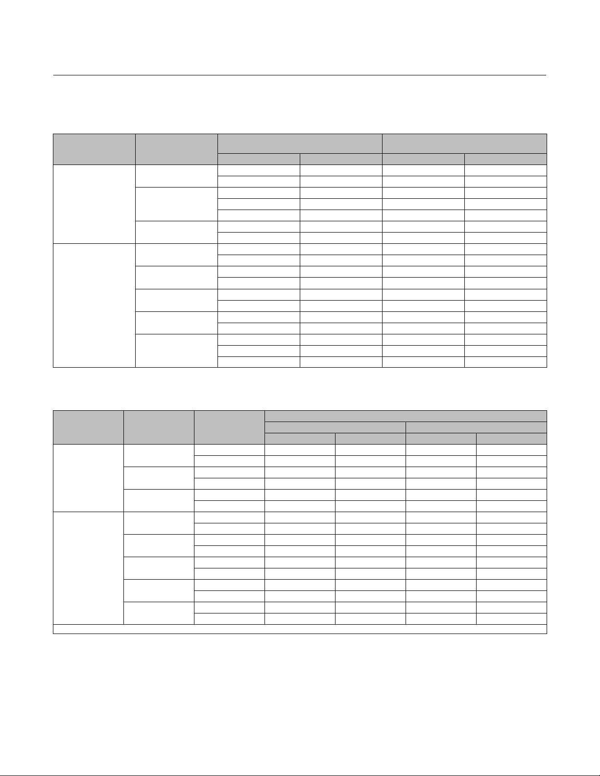
Table 2. Maximum Allowable Actuator Thrust for Standard Style 3 Bonnet Extension Length
MAXIMUM ALLOWABLE STEM LOAD
FOR S20910 STEM MATERIAL
VALVE VALVE SIZE, NPS
1
HPS-C
HPT-C
2
3
4
6
8
10
12
STEM DIAMETER
mm Inches N lb
12.7 1/2 15413 3465
19.1 3/4 45176 10156
12.7 1/2 16458 3700
19.1 3/4 46738 10507
25.4 1 95130 21386
19.1 3/4 48873 10987
25.4 1 89956 20223
19.1 3/4 48055 10803
25.4 1 89956 20223
25.4 1 83382 18745
31.8 1 1/4 139185 31290
25.4 1 83840 18848
31.8 1 1/4 139741 31415
25.4 1 77662 17459
31.8 1 1/4 133393 29988
25.4 1 80446 18085
31.8 1 1/4 136280 30637
50.8 2 378326 85051
HPS-C and HPT-C Valves
September 2020
Table 3. Approximate Weights (Valve and Bonnet Assemblies)
VALVE VALVE SIZE, NPS RATING
kg lb kg lb
1
HPS-C
HPT-C
1. (Long) indicates industry standard long face-to-face.
2
3
4 (long)
6 (long)
8
10
12
(1)
(1)
CL900 and 1500 51 113 48 105
CL2500 55 120 44 96
CL900 and 1500 81 178 61 135
CL2500 113 249 84 184
CL900 135 296 - - - - - -
CL1500 138 304 106 233
CL900 240 527 - - - - - -
CL1500 258 568 211 464
CL900 521 1147 - - - - - -
CL1500 567 1248 465 1023
CL900 809 1779 644 1417
CL1500 999 2198 781 1718
CL900 1087 2392 887 1951
CL1500 1560 3432 1193 2625
CL900 1349 2967 1044 2297
CL1500 1953 4296 1425 3134
END CONNECTION
Flange SWE, BWE
3

HPS-C and HPT-C Valves
September 2020
Instruction Manual
D104208X012
Installation
WARNING
Always wear protective gloves, clothing, and eyewear when performing any installation operations to avoid personal
injury.
Personal injury or equipment damage caused by sudden release of pressure may result if the valve assembly is installed
where service conditions could exceed the limits given in table 1 or on the appropriate nameplates. To avoid such injury or
damage, provide a relief valve for over‐pressure protection as required by government or accepted industry codes and
good engineering practices.
Check with your process or safety engineer for any additional measures that must be taken to protect against process
media. If installing into an existing application, also refer to the warning at the beginning of the Maintenance section in this
instruction manual.
WARNING
When ordered, the valve configuration and construction materials were selected to meet particular pressure, temperature,
pressure drop, and controlled fluid conditions. Because some valve body/trim material combinations are limited in their
pressure drop and temperature ranges, do not apply any other conditions to the valve without first contacting your
Emerson sales office
.
WARNING
Some bonnet flanges have a tapped hole that was used to handle the bonnet during manufacture. Do not use this tapped
hole to lift the valve assembly or personal injury may result.
1. Before installing the valve, inspect the valve and associated equipment for any damage and any foreign material.
2. Make certain the valve body interior is clean, that pipelines are free of foreign material, and the valve is oriented so
that pipeline flow is in the same direction as the arrow on the side of the valve.
Note
NPS 8 to 12 CL900 and CL1500 HPT-C valves contain a flow vane in the lower flow passage. This is critical to proper function of the
valve and is not a defect.
3. Gas Service: The normal method of mounting for gas service is with the actuator vertical above the valve body.
However, the control valve assembly may be installed in any orientation unless limited by seismic criteria. Other
positions may result in uneven valve plug and cage wear that could result in improper operation. For mounting
assistance, consult your Emerson sales office
.
CAUTION
To avoid possible damage to the packing, do not allow the installed actuator angle to be so flat as to allow liquid inside the
bonnet to come in contact with the packing.
Also, if insulation is applied, do not let the insulation run up the extension bonnet. This could cause the packing to freeze
and be damaged.
4

Instruction Manual
D104208X012
HPS-C and HPT-C Valves
September 2020
Liquid Service: The preferred method of mounting for liquid service is with the actuator vertical above the valve body.
This will allow a vapor layer to form between the liquid and the packing. If there are piping constraints, the actuator
can be angled slightly from vertical. However, in no case should the angle be so flat as to allow liquid inside the bonnet
to come in contact with the packing. For mounting assistance, consult your Emerson sales office.
4. If insulation is applied, make sure it is applied only to the body/bonnet joint. Do not let the insulation run up the
extension bonnet.
5. Use accepted piping and welding practices when installing the valve in the line. For flanged valve bodies, use a
suitable gasket between the valve body and pipeline flanges.
6. If the actuator and valve are shipped separately, refer to the actuator mounting procedure in the appropriate
actuator instruction manual.
7. If the valve body was shipped without packing installed in the packing box, install the packing before putting the
valve body into service. Refer to instructions given in the Packing Maintenance procedure.
WARNING
Personal injury could result from packing leakage. Valve packing was tightened before shipment; however, the packing
might require some readjustment to meet specific service conditions.
Valves with ENVIRO‐SEAL™ live‐loaded packing will not require this initial readjustment. See the Fisher instruction
manual ENVIRO‐SEAL Packing System for Sliding‐Stem Valves (D101642X012
convert your present packing arrangement to ENVIRO‐SEAL packing, refer to the retrofit kits listed in the parts kit
sub‐section near the end of this manual.
) for packing instructions. If you wish to
Maintenance
Valve parts are subject to normal wear and must be inspected and replaced as necessary. Inspection and maintenance
frequency depends on the severity of service conditions. This section includes instructions for packing maintenance
and trim maintenance. All maintenance operations may be performed with the valve in the line.
WARNING
Avoid personal injury or property damage from sudden release of process pressure. Before performing any maintenance
operations:
D Do not remove the actuator from the valve while the valve is still pressurized.
D Always wear protective gloves, clothing, and eyewear when performing any maintenance operations to avoid personal
injury.
D Disconnect any operating lines providing air pressure, electric power, or a control signal to the actuator. Be sure the
actuator cannot suddenly open or close the valve.
D Use bypass valves or completely shut off the process to isolate the valve from process pressure. Relieve process pressure
from both sides of the valve. Drain the process media from both sides of the valve.
D Vent the pneumatic actuator loading pressure and relieve any actuator spring precompression.
D Use lock‐out procedures to be sure that the above measures stay in effect while you work on the equipment.
D The valve packing box may contain process fluids that are pressurized, even when the valve has been removed from the
pipeline. Process fluids may spray out under pressure when removing the packing hardware or packing rings, or when
loosening the packing box pipe plug.
D Check with your process or safety engineer for any additional measures that must be taken to protect against process
media.
5

HPS-C and HPT-C Valves
September 2020
Instruction Manual
D104208X012
CAUTION
Follow instructions carefully to avoid damaging the product surfaces, which could result in damage to the product.
Note
The HPS-C/HPT-C valves use spiral-wound gaskets which are crushed to provide their seal. A spiral-wound gasket should never be
reused. Whenever a gasket seal is disturbed by removing or shifting parts, a new gasket should be installed upon reassembly. This
is necessary to ensure a good gasket seal because the used gasket may not seal properly.
Packing Maintenance
This section covers PTFE V‐ring, double PTFE, and graphite packing used in extension bonnets (figure 2).
Note
If the valve has ENVIRO‐SEAL live‐loaded packing installed, refer to the instruction manual ENVIRO‐SEAL Packing System for Sliding
Stem Valves (D101642X012
) for packing instructions. Figure 4 shows typical ENVIRO‐SEAL arrangements.
Standard packing key numbers are shown in figure 2. ENVIRO-SEAL packing key numbers are shown in figure 4. Bonnet
and valve key numbers are shown in figures 5, 6, and 7.
For spring-loaded single PTFE V-ring packing, the spring (key 24) maintains a sealing force on the packing. If leakage is
noted around the packing follower (key 28), check to be sure the shoulder on the packing follower is touching the
bonnet. If the shoulder is not touching the bonnet, tighten the packing flange nuts (key 20), until the shoulder is
against the bonnet. If leakage cannot be stopped in this manner, proceed with replacing packing procedures.
If there is undesirable packing leakage with other than spring‐loaded packing, first try to limit the leakage and
establish a stem seal by tightening the packing flange nuts.
If the packing is relatively new and tight on the stem, and if tightening the packing flange nuts does not stop the
leakage, it is possible that the valve stem is worn or nicked so that a seal cannot be made. The surface finish of a new
valve stem is critical for making a good packing seal. If the leakage comes from the outside diameter of the packing, it
is possible that the leakage is caused by nicks or scratches around the packing box wall. If performing any of the
following procedures, inspect the valve stem and packing box wall for nicks and scratches. If leakage continues,
replace the packing by following the numbered steps presented in the replacing packing procedure.
Adding Packing Rings
Key numbers referred to in this procedure are shown in figures 2, 5, and 6 unless otherwise noted.
When using packing with a lantern ring (key 24) it may be possible to add packing rings above the lantern ring as a
temporary measure without removing the actuator from the valve body.
1. Isolate the control valve from the line pressure, release pressure from both sides of the valve body, and drain the
process media from both sides of the valve. If using a power actuator, also shut‐off all pressure lines to the power
actuator, release all pressure from the actuator. Use lock‐out procedures to be sure that the above measures stay in
effect while you work on the equipment.
2. Remove the packing flange nuts (key 20) and lift the packing flange, upper wiper, and packing follower (keys 18, 27,
and 28) away from the valve body.
6
Instruction Manual
D104208X012
HPS-C and HPT-C Valves
September 2020
3. It may be possible to dig out the old packing rings on top of the lantern ring, but use care to avoid scratching the
valve plug stem or packing box wall. Clean all metal parts to remove particles that would prevent the packing from
sealing.
4. Remove the stem connector and slip the packing rings over the end of the valve plug stem.
5. Reassemble the packing follower, upper wiper, packing flange, and packing flange nuts (keys 28, 27, 18, and 20).
6. Reconnect the body‐actuator stem connection according to the appropriate actuator instruction manual.
7. Tighten the packing flange nuts only far enough to stop leakage under operating conditions. Check for leakage
around the packing follower when the valve is being put into service. Retighten the packing flange nuts as required
(see table 3).
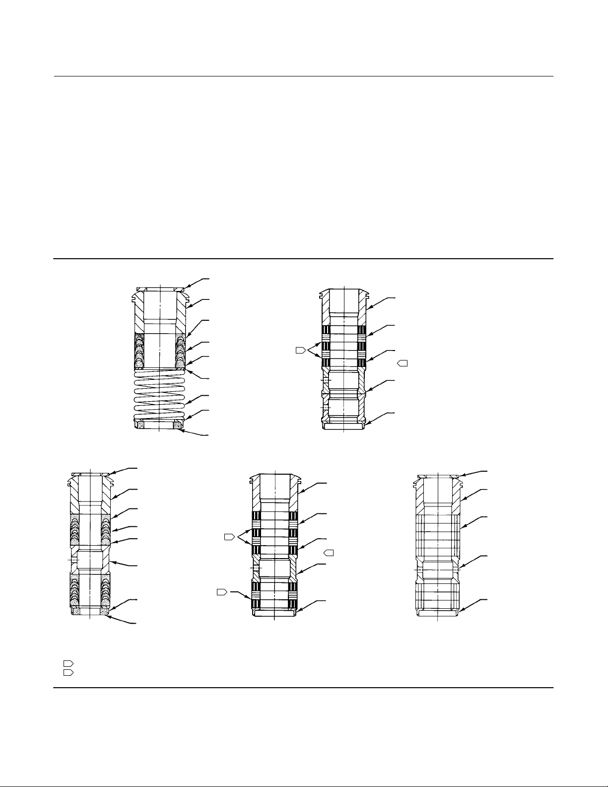
Figure 2. Packing Arrangements
UPPER WIPER (KEY 27)
12A8160-A
PTFE V‐RING
SINGLE PACKING
UPPER WIPER (KEY 27)
PACKING FOLLOWER
(KEY 28)
FEMALE ADAPTOR
(KEY 35)
V-RING (KEY 23)
MALE ADAPTOR
(KEY 34)
LANTERN RING (KEY 24)
PACKING FOLLOWER
(KEY 28)
FEMALE ADAPTOR
(KEY 35)
V-RING (KEY 23)
MALE ADAPTOR
(KEY 34)
WASHER (KEY 25)
SPRING (KEY 24)
PACKING BOX RING
(KEY 26)
LOWER WIPER
(KEY 33)
KEY 22
}
1
KEY 22
}
1
14A3412-C
GRAPHITE RIBBON AND FILAMENT
SINGLE PACKING
PACKING FOLLOWER
(KEY 28)
GRAPHITE RIBBON
PACKING RING (KEY 23)
GRAPHITE FILAMENT
PACKING RING (KEY 23)
2
LANTERN RING
(KEY 24)
PACKING FOLLOWER
(KEY 28)
GRAPHITE RIBBON
PACKING RING (KEY 23)
GRAPHITE FILAMENT
PACKING RING (KEY 23)
2
LANTERN RING
(KEY 24)
PACKING BOX RING
(KEY 26)
UPPER WIPER
(KEY 27)
PACKING
FOLLOWER
(KEY 28)
PACKING RING
(KEY 23)
LANTERN RING
(KEY 24)
PACKING BOX RING
(KEY 26)
12A7839-A Sht 1
PTFE V‐RING
LOWER WIPER
(KEY 33)
DOUBLE PACKING
NOTES:
0.102 mm (0.004 INCH) THICK SACRIFICIAL ZINC WASHERS. USE ONLY ONE BELOW EACH GRAPHITE RIBBON RING.
1
2
HAS THE APPEARANCE OF A WOVEN OR BRAIDED RING.
C0747‐1
1
14A3414-C
GRAPHITE RIBBON AND FILAMENT
DOUBLE PACKING
PACKING BOX RING
(KEY 26)
12A8163-A
PTFE/COMPOSITION
DOUBLE PACKING
PACKING BOX RING
(KEY 26)
7

HPS-C and HPT-C Valves
September 2020
Instruction Manual
D104208X012
Replacing Packing
WARNING
Refer to the warning at the beginning of the Maintenance section in this instruction manual.
Key numbers and sequence of assembly of packing parts are shown in figure 2. Bonnet and valve key number locations
are shown in figures 5, 6, and 7, unless otherwise noted.
1. Isolate the control valve from the line pressure, release pressure from both sides of the valve body, and drain the
process media from both sides of the valve. If using a power actuator, also shut‐off all pressure lines to the power
actuator, release all pressure from the actuator. Use lock‐out procedures to be sure that the above measures stay in
effect while you work on the equipment. Observe the warnings at the start of the Maintenance section.
2. Disconnect the operating lines from the actuator and any leak-off piping from the bonnet. Disconnect the stem
connector and remove the actuator from the valve by unscrewing the yoke locknut (key 32) or hex nuts (key 30).
3. Loosen the packing flange nuts (key 20) so that the packing is not tight on the valve stem. Remove any travel
indicator parts and stem locknuts from the valve stem threads.
WARNING
To avoid personal injury or property damage caused by uncontrolled movement of the bonnet, loosen the bonnet by
following the instructions in the next steps.
Do not remove a stuck bonnet by pulling on it with equipment that can stretch or store energy in any other manner. The
sudden release of stored energy can cause uncontrolled movement of the bonnet. If the cage sticks to the bonnet, proceed
carefully with bonnet removal and support the cage so that it will not fall unexpectedly from the bonnet.
4. When lifting the bonnet, be sure the plug and stem assembly (key 4 and 5), cage (key 2), and cage retainer (key 45),
if applicable, remain in the valve body. This avoids damage to the seating surfaces as a result of the assembly
dropping from the bonnet after being lifted part way out. The parts are also easier to handle separately.
WARNING
To avoid possible personal injury, review your process shutdown procedures to be sure process pressure is not applied to
the valve for the following procedure.
5. Hex nuts (key 13) attach the bonnet to the valve body (key 1). Loosen these nuts or cap screws approximately 3 mm
(1/8 inch). Then, loosen the body-to-bonnet joint by either rocking the bonnet or prying between the bonnet and
valve body. Work with a prying tool around the bonnet until the bonnet loosens.
D If fluid leaks from the joint, it may indicate that process pressure is applied to the valve. Review your process
shutdown procedures, and be sure process pressure is not applied to the valve.
D If no fluid leaks from the joint, proceed to the next step.
6. Unscrew the hex nuts (key 13) and carefully lift the bonnet off the valve stem. If the valve plug and stem assembly
starts to lift with the bonnet, use a brass or lead hammer on the end of the stem and tap it back down. Set the
bonnet on a cardboard or wooden surface to prevent damage to the bonnet gasket surface.
8

Instruction Manual
(1)
D104208X012
HPS-C and HPT-C Valves
September 2020
Table 4. Recommended Torque for Packing Flange Nuts
STEM
DIAMETER
mm Inches Min Max Min Max
12.7 1/2
19.1 3/4
25.4 1
31.8 1‐1/4
50.8 2 CL1500 98 146 72 108
1. For intermediate class ratings, use the same torque as the next lower standard class.
PRESSURE
(1)
RATING
CL900 12 18 9 13
CL1500 15 22 11 16
CL2500 18 24 13 18
CL900 27 41 20 30
CL1500 34 50 25 37
CL2500 41 61 30 45
CL900 42 62 31 46
CL1500 52 77 38 57
CL2500 61 91 45 67
CL900 56 83 41 61
CL1500 68 102 50 75
NSm lbfSft
TORQUE
7. If it is necessary to remove and inspect the valve trim, refer to the following Trim Maintenance section.
8. Remove the bonnet gasket (key 10) and cover the opening in the valve to protect the gasket surface and prevent
foreign material from getting into the valve body cavity.
9. Remove the packing flange nuts, packing flange, upper wiper, and packing follower (keys 20, 18, 27, and 28).
Carefully push out all the remaining packing parts from the valve side of the bonnet using a rounded rod or other
tool that will not scratch the packing box wall. Clean the packing box and metal packing parts.
Table 5. Torque for Body‐to‐Bonnet Bolting Using Anti‐Seize Lubricant
TORQUE
STUD SIZE
3/4 260 190
7/8 370 275
1-1/8 710 525
1-1/4 940 695
1-3/8 1270 935
1-1/2 1650 1220
1-5/8 2130 1570
1-3/4 2670 1970
1. For other materials, contact your Emerson sales office for torques.
NSm lbfSft
B8M, B8M2, S20910 Studs
10. Inspect the valve stem threads and packing box surfaces for any sharp edges which might cut the packing.
Scratches or burrs in the packing box surfaces could cause leakage or damage to the new packing. If the surface
condition cannot be improved by light sanding, replace the damaged parts.
11. If necessary, go to the Trim Maintenance procedures to remove, inspect or replace trim parts. Return to this section
when installing the bonnet on the valve body.
9

HPS-C and HPT-C Valves
September 2020
Instruction Manual
D104208X012
Installing the Bonnet
1. Remove the covering protecting the valve body cavity and install a new bonnet gasket (key 10), making sure the
gasket seating surfaces are clean and smooth. Then slide the bonnet over the stem and onto the stud bolts (key 12).
Note
Stud(s) and nut(s) should be installed such that the manufacturer's trademark and material grade marking is visible, allowing easy
comparison to the materials selected and documented in the Emerson/Fisher serial card provided with this product.
WARNING
Personal injury or damage to equipment could occur if improper stud and nut materials or parts are used. Do not operate or
assemble this product with stud(s) and nut(s) that are not approved by Emerson/Fisher engineering and/or listed on the
serial card provided with this product. Use of unapproved materials and parts could lead to stresses exceeding the design
or code limits intended for this particular service. Install studs with the material grade and manufacturer's identification
mark visible. Contact your Emerson sales office
suspected.
immediately if a discrepancy between actual parts and approved parts is
2. Lubricate the stud threads and the faces of the hex nuts (key 13) with anti-seize lubricant (not necessary if new
factory pre lubricated hex nuts are used). Replace the hex nuts and tighten them finger-tight. Stroke the valve
several times to center the trim.
Torque the nuts in a crisscross pattern to no more than 1/4 of the nominal torque value specified in table 4. When
all nuts are tightened to that torque value, increase the torque by 1/4 of the specified nominal torque and repeat
the crisscross pattern. Repeat this procedure until all nuts are tightened to the specified nominal value. Apply the
final torque value again and, if any nut still turns, tighten every nut again
3. Install new packing and the metal packing box parts according to the appropriate arrangement in figure 2. Place a
smooth-edged pipe over the valve stem and gently tap each soft packing part into the packing box.
4. Slide the packing follower, upper wiper, and packing flange (keys 28, 27, and 18) into position. Lubricate the
packing flange studs (key 19) and faces of the packing flange nuts (key 20). Install the packing flange nuts.
5. Tightening packing flange nuts (key 20):
D For spring-loaded PTFE V-ring packing, tighten the packing flange nuts until the shoulder on the packing follower
(key 28) contacts the bonnet.
D For graphite packing, tighten the packing flange nuts to the maximum recommended torque shown in table 3.
Then, loosen the packing flange nuts, and retighten them to the recommended minimum torque shown in
table 3.
D For other packing types, tighten the packing flange nuts alternately in small equal increments until one of the nuts
reaches the minimum recommended torque shown in table 3. Then, tighten the remaining nut until the packing
flange is level and at a 90 degree angle to the valve stem.
D For ENVIRO-SEAL live-loaded packing; refer to the Fisher instruction manual ENVIRO-SEAL Packing System for
Sliding-Stem Valves (D101642X012
).
6. Mount the actuator on the valve assembly and reconnect the actuator and valve stem according to the procedure in
the appropriate actuator instruction manual.
10

Instruction Manual
D104208X012
HPS-C and HPT-C Valves
September 2020
Trim Maintenance
This procedure describes how the valve trim can be completely disassembled. When inspection or repairs are required,
perform only those steps necessary to accomplish the task.
Key number locations are shown in figures 5 and 6 for NPS 1 through 6, and figure 7 for NPS 8 through 12, unless
otherwise noted.
WARNING
Refer to the WARNING at the beginning of the Maintenance section in this instruction manual.
To avoid personal injury due to leaking fluids, avoid damaging gasket sealing surfaces. The surface finish of the valve stem
(key 5) is critical for making a good packing seal.
The inside surface of the cage (key 2) is critical for tight shutoff and smooth operation of the valve plug. The seating
surfaces of the valve plug (key 4) and seat ring (key 3) are critical for proper shutoff. Protect these surfaces accordingly.
Trim Disassembly NPS 1 through 6
1. Remove the actuator and the bonnet according to steps 1 through 6 of the Replacing Packing procedures in the
Maintenance section.
2. Lift the valve stem and attached valve plug out of the valve body. If the valve plug is to be reused, tape or otherwise
protect the valve plug stem and the valve plug seating surface to prevent scratches.
3. Lift out the cage (key 2) and the bonnet gasket (key 10).
4. Remove the seat ring (key 3) and seat ring gasket (key 11).
5. Clean, inspect, and if necessary obtain replacement parts.
Trim Disassembly NPS 8 through 12
1. Remove the actuator and the bonnet according to steps 1 through 6 of the Replacing Packing procedures in the
Maintenance section.
2. Lift the valve stem and attached valve plug out of the valve body. If the valve plug is to be reused, tape or otherwise
protect the valve plug stem and the valve plug seating surface to prevent scratches.
3. Lift out the cage retainer (key 45), cage gaskets (key 43), and the bonnet gasket (key 10).
WARNING
Lifting of the cage must be done with a vertical or straight lift using the equipment shown in figure 3. Lifting at angle may
damage the lifting equipment and cause property damage or personal injury.
4. Install threaded rods (about 6 inches long) into the holes on top of the cage vertically. Install hoist rings, nuts or eye
bolt on to the threaded rods (see figure 3). Lift out the cage with the hoist nut from the valve body.
11

HPS-C and HPT-C Valves
September 2020
Instruction Manual
D104208X012
Figure 3. Removal of Cage with Hoist Rod and Nut
Note
The cage and cage retainer lifting holes are provided for ease of disassembly. To prevent damage to the cage lifting hole, fully
engage the threaded rod into the cage hole, but do not overtighten the hoist rod. It only needs to be hand tight.
If it is hard to lift the cage, a piece of wood and a hammer can be used to strike on the top chamfer of the cage to loosen it from the
body or seat ring gasket.
ASTM A193 B7 or comparable threaded rods are required for cage removal. Contact your Emerson sales office
information.
HOIST NUT
HOIST ROD
BODY
CAGE
for more
5. Remove the seat ring gasket (key 11).
6. Clean, inspect, and if necessary obtain replacement parts.
Valve Plug Maintenance
CAUTION
To avoid the valve plug seal ring (key 7) not sealing properly and affecting valve performance, be careful not to scratch the
surfaces of the ring groove on the valve plug or any of the surfaces of the replacement ring.
1. With the valve plug (key 4) removed, according to the disassembly portion of the Trim Maintenance procedure,
proceed as follows: For HPS-C valves, proceed to step 5:
2. For HPT-C valves, the spring-loaded seal ring may be removed by first working the retaining ring (key 9) off with a
screwdriver. Then carefully slide the metal backup ring (key 8) and seal ring (key 7) off the valve plug (key 4).
3. A spring-loaded seal ring must be installed so that its open side faces toward the valve stem, or toward the seat of
the plug depending on flow direction. To install a spring-loaded seal ring, slide the seal ring (key 7) onto the valve
plug followed by the metal backup ring (key 8).
4. Then install the retaining ring (key 9) by inserting one end in the groove and, while turning the plug, press the ring
into the groove. Again, be careful not to scratch any surfaces of the ring or plug.
12

Instruction Manual
D104208X012
HPS-C and HPT-C Valves
September 2020
CAUTION
To avoid weakening the stem that may cause failure in service, never reuse an old stem with a new valve plug. Using an old
stem with a new plug requires drilling a new pin hole in the stem, which will weaken the stem. However, a used valve plug
may be reused with a new stem.
5. To replace the valve stem (key 5), drive or drill out the pin (key 6). Unscrew the valve plug from the stem.
6. Screw the new stem into the valve plug. Tighten to the torque value given in table 5. Also, use this table to select
the proper drill size. Drill through the stem using the hole in the valve plug as a guide. Remove any chips or burrs
and drive in a new pin to lock the assembly.
Trim Assembly NPS 1 through 6
Key number locations are shown in figure 5 and 6, unless otherwise noted.
1. Install the seat ring gasket (key 11), and seat ring (key 3).
2. Install the cage (key 2). Any rotational orientation of the cage with respect to the valve body is acceptable.
3. Lower the valve plug (key 4) and stem assembly into the cage. Make sure the seal ring (key 7) is evenly engaged in
the entrance chamfer at the top of the cage (key 2) to avoid damaging the ring.
4. Place the gaskets (keys 10) on top of the cage.
5. Mount the bonnet on the valve body and complete assembly using the Replacing Packing procedures in the
Maintenance section. Torque guidelines for body-to-bonnet bolting are shown in table 4.
6. If the valve has soft metal-to-metal seats, refer to the Coining Soft Metal-to-Metal Seats section, below.
Trim Assembly NPS 8 through 12
Key number locations are shown in figure 7 unless otherwise noted.
1. Install the seat ring gasket (key 11) in the lower gasket groove in the valve body (key 1), making sure the gasket is
centered in the groove and the bottom of the gasket is flush with the mating surface in the body.
2. Install threaded rods (about 6” long) into the holes on top of the cage vertically. Install hoist rings, nuts or eye bolt
on to the threaded rods.
Note
The cage and seat ring lifting holes are 1/4”-20. To prevent damage to the cage/seat ring lifting holes, fully engage the threaded
rod into the cage/seat ring hole, but do not overtighten the hoist rod. It only needs to be hand tight.
ASTM A193 B7 or comparable threaded rods are required for cage/seat ring installation.
3. Lift the cage (key 2) using the hoist rings on the threaded rods and install the cage into the valve body (see figure 3).
Any rotational orientation of the cage with respect to the valve body is acceptable. When installing the cage, take
care to lower the cage evenly and ensure the cage will not damage the flat sheet gasket (key 11).
4. Install quantity-2 cage gaskets (key 43) and make sure the gaskets sit flush on the surface of the groove.
5. Install the cage retainer (key 45) on top of the cage and a single cage gasket (key 43) on top of the cage retainer.
6. Install the bonnet gasket (key 10) into the groove around the valve body trim opening.
7. Lower the valve plug (key 4) and stem assembly through the bore of the cage retainer (key 45) and into the bore of
the cage (key 2) and gently rest the plug seating surface against the seating surface in the cage. Make sure the seal
13

HPS-C and HPT-C Valves
September 2020
Instruction Manual
D104208X012
ring (key 7) is evenly engaged in the entrance chamfer at the top of the cage retainer (key 45) to avoid damaging
the ring.
8. Mount the bonnet on the valve body and complete assembly using the Replacing Packing procedures in the
Maintenance section. Torque guidelines for body-to-bonnet bolting are shown in table 4.
9. If the valve has soft metal-to-metal seats, refer to the Coining Soft Metal-to-Metal Seats section.
Note
Be careful to prevent the bonnet from crushing the spiral wound gaskets as the bonnet is lowered on to the valve.
Damaging the gaskets will require that they are replaced.
Table 6. Valve Stem Connection Torque and Drill Size for Pin Hole
VALVE STEM
DIAMETER
mm Inches NSm LbfSft Inches
12.7 1/2 81 ‐ 115 60 ‐ 85 1/8
19.1 3/4 237 ‐ 339 175 ‐ 250 3/16
25.4 1 420 - 481 310 - -355 1/4
31.8 1‐1/4 827 ‐ 908 610 ‐ 670 1/4
50.8 2 3515-3885 2600-2880 3/8
VALVE STEM
CONNECTION TORQUE
(MINIMUM‐MAXIMUM)
DRILL SIZE
FOR PIN
Coining Soft Metal‐to‐Metal Seats
Soft metal‐to‐metal seat constructions consist of a valve plug with hardfaced CoCr‐A seat and a non‐hardfaced S31600
seat ring or cage seating surface. For optimum shutoff performance of these constructions, coin seats by stroking the
valve plug into the seat ring at least three times with maximum actuator force.
CAUTION
To avoid possible product damage which may affect performance, do not lap soft metal‐to‐metal seats.
14

Instruction Manual
D104208X012
HPS-C and HPT-C Valves
September 2020
Parts Ordering
Each body‐bonnet assembly is assigned a serial number which can be found on the valve. This same number also
appears on the actuator nameplate when the valve is shipped from the factory as part of a control valve assembly.
Refer to the serial number when contacting your Emerson sales office
for technical assistance. When ordering
replacement parts, refer to the serial number and to the eleven‐character part number for each part required from the
following parts kit or parts list information.
WARNING
Use only genuine Fisher replacement parts. Components that are not supplied by Emerson Automation Solutions should
not, under any circumstances, be used in any Fisher valve, because they may void your warranty, might adversely affect the
performance of the valve, and could cause personal injury and property damage.
Parts Kits
Packing Kits
Standard Packing Repair Kits (Non Live‐Loaded)
Stem Diameter, mm (Inches)
Yoke Boss Diameter, mm (Inches)
PTFE (Contains keys 22, 24, 25, 26, 27) RPACKX00022 RPACKX00032 RPACKX00342 RPACKX00352
Double PTFE (Contains keys 22, 24, 26, 27) RPACKX00052 RPACKX00062 RPACKX00362 RPACKX00372
Single Graphite Ribbon/Filament (Contains keys 23 [ribbon ring],
23 [filament ring], 24, and 26)
Single Graphite Ribbon/Filament (Contains keys 23 [ribbon ring],
23 [filament ring], and 26)
Single Graphite Ribbon/Filament (Contains keys 23 [ribbon ring],
23 [filament ring])
12.7 (1/2)
71 (2-13/16)
RPACKX00112 RPACKX00122 ---- ---
--- --- RPACKX00532 RPACKX00542 RPACKX00552
RPACKX00142 RPACKX00152 ---- ---
19.1 (3/4)
90 (3-9/16)
25.4 (1)
127 (5)
31.8 (1-1/4)
127 (5, 5H)
50.8 (2)
178 (7)
Consult sales
office
Consult sales
office
ENVIRO‐SEAL Packing Retrofit Kits
Retrofit kits include parts to convert valves with existing standard bonnets to the ENVIRO-SEAL packing box
construction. Refer to figure 4 for key numbers for PTFE and Graphite ULF packing.
Stems and packing box constructions that do not meet Fisher stem finish specifications, dimensional tolerances, and
design specifications, may adversely alter the performance of this packing kit.
ENVIRO‐SEAL Packing Retrofit Kits
Stem Diameter, mm (Inches)
Yoke Boss Diameter, mm (Inches)
Double PTFE (Contains keys 200, 201, 211, 212,
214, 215, 216, 217, 218, tag, cable tie)
Graphite ULF (Contains keys 200, 201, 207, 208, 209,
210, 211, 212, 214, 217, tag, cable tie)
Duplex (Contains keys 200, 201, 207, 209, 211, 212, 214, 215,
216, 217, tag, cable tie)
12.7 (1/2)
71 (2-13/16)
RPACKXRT022 RPACKXRT032 RPACKXRT042 RPACKXRT052
RPACKXRT272 RPACKXRT282 RPACKXRT292 RPACKXRT302
RPACKXRT222 RPACKXRT232 RPACKXRT242 RPACKXRT252
19.1 (3/4)
90 (3-9/16)
25.4 (1)
127 (5)
31.8 (1-1/4)
127 (5, 5H)
50.8 (2)
178 (7)
Consult sales
office
15

HPS-C and HPT-C Valves
September 2020
Instruction Manual
D104208X012
ENVIRO‐SEAL Packing Repair Kits
Repair kits include parts to replace the “soft” packing materials in valves that already have ENVIRO-SEAL packing
arrangements installed or in valves that have been upgraded with ENVIRO-SEAL retrofit kits. Refer to figure 4 for key
numbers for PTFE and Graphite ULF packing.
Stems and packing box constructions that do not meet Fisher stem finish specifications, dimensional tolerances, and
design specifications, may adversely alter the performance of this packing kit.
ENVIRO‐SEAL Packing Repair Kits
Stem Diameter, mm (Inches)
Yoke Boss Diameter, mm (Inches)
Double PTFE (Contains keys 214, 215, & 218) RPACKX00202 RPACKX00212 RPACKX00222 RPACKX00232
Graphite ULF (Contains keys 207, 208, 209, 210, and 214) RPACKX00602 RPACKX00612 RPACKX00622 RPACKX00632
Duplex (Contains keys 207, 209, 214, and 215) RPACKX00302 RPACKX00312 RPACKX00322 RPACKX00332
Figure 4. Enviro-seal Packing
12.7 (1/2)
71 (2-13/16)
19.1 (3/4)
90 (3-9/16)
25.4 (1)
127 (5)
31.8 (1-1/4)
127 (5, 5H)
50.8 (2)
178 (7)
Consult sales
office
STUD
(KEY 200)
HEX NUT
(KEY 212)
PACKING
FLANGE
(KEY 201)
PACKING
RING
(KEY 209)
PACKING
RING
(KEY 210)
PACKING
BOX RING
(KEY 211)
39B64612
TYPICAL ENVIRO-SEAL PACKING SYSTEM
WITH GRAPHITE ULF PACKING
213
SPRING PACK
ASSEMBLY
(KEY 217)
GUIDE
BUSHING
(KEY 207)
PACKING
WASHERS
(KEY 214)
GUIDE
BUSHING
(KEY 208)
212
201
215
216
207
209
211
200
213
217
207
207
214
207
A6722
TYPICAL ENVIRO-SEAL PACKING SYSTEM
WITH DUPLEX PACKING
16

Instruction Manual
(1,2)
D104208X012
Gasket Kit
VALVE RATING VALVE SIZE, NPS
HPS-C
CL1500
HPT-C
CL1500
HPS-C
CL2500
Gasket Set HPT-C NPS 8 through 12
VALVE RATING
CL900
CL1500
1. Includes Bonnet Gasket (key 10), Cage Gasket (key 43), and Seat Ring Gasket (key 11).
2. Gaskets should always be replaced as sets, not separately.
HPS-C and HPT-C Valves
MATERIAL
N06600/Graphite N07750/Graphite
1 12B7100X012 12B7100X022
2 12B7100X032 12B7100X042
3 12B7100X052 12B7100X062
4 12B7100X082 --6 12B7100X112 --1 12B7100X152 12B7100X122
2 12B7100X162 12B7100X132
HP GLOBE MATERIAL
Valve Size, NPS
8 GG53667X012 GG53677X012 GG53849X012
10 GG53684X012 GG53685X012 GG53852X012
12 GG53692X012 GG53693X012 GG53854X012
8 GG53678X012 GG53679X012 GG53849X012
10 GG53686X012 GG53687X012 GG53852X012
12 GG53694X012 GG53695X012 GG53854X012
Bonnet Spiral
Wound Gasket
N06600/Graphite
Cage Spiral
Wound Gasket
N06600/Graphite
S31600/Graphite
September 2020
Seat Ring Flat
Sheet Gasket
17

HPS-C and HPT-C Valves
September 2020
Instruction Manual
D104208X012
Parts List
Numerous available combinations of valve parts make
selection of some parts difficult; when ordering valve
parts, provide the valve serial number with the order,
permitting proper selection of replacement parts to be
made at the factory.
Note
Contact your Emerson sales office
Key Description
1 Valve Body
If you need a valve body as a replacement part, order by valve
size, serial number, and desired material.
2* Cage
3* Seat Ring
4* Valve Plug
5* Valve Stem
6* Pin
7* Seal Ring
8* Back Up Ring
9* Retaining Ring (for HPT-C only)
10* Bonnet Gasket
for Part Ordering information.
Key Description
11* Seat Ring Gasket
12 Stud
13 Hex Nut
14 Anti‐Seize Lubricant
15 Nameplate
16 Wire
17 Bonnet
If you need a bonnet as a replacement part, order by valve size
and stem diameter, serial number, and desired material.
18 Packing Flange
19 Stud Bolt
20 Hex Nut
22* Packing Set See Parts Kits
23* Packing Ring See Parts Kits
24 Spring or Lantern Ring See Parts Kits
25 Washer, Special See Parts Kits
26* Packing Box Ring See Parts Kits
27* Upper Wiper See Parts Kits
28 Follower
29 Stud Bolt
30 Hex Nut
32 Yoke Locknut
36 Baffle
37 Retaining Ring
38 Drive Screw
40 Washer
41 Flow Arrow
43 Cage Gasket
44 Nameplate
45 Cage Retainer
18
*Recommended spare parts

Instruction Manual
D104208X012
Figure 5. Fisher HPS-C Valve Assembly
HPS-C and HPT-C Valves
September 2020
GE87219
FLOW
19

HPS-C and HPT-C Valves
September 2020
Figure 6. Fisher HPT-C Valve Assembly NPS 1 through 6
Instruction Manual
D104208X012
FLOW UP
FLOW DOWN
FLOW
VIEW A
20
GE87206

Instruction Manual
D104208X012
Figure 7. Fisher HPT-C Valve Assembly NPS 8 through 12
HPS-C and HPT-C Valves
September 2020
VIEW A
FLOW UP
FLOW
VIEW A
VIEW A
FLOW DOWN
FLOW DIRECTION UP
FLOW DIRECTION DOWN
GH10487
j APPLY LUB
NOTE: PARTS NOT SHOWN: 15, 16, AND 44
21

HPS-C and HPT-C Valves
September 2020
Instruction Manual
D104208X012
22

Instruction Manual
D104208X012
HPS-C and HPT-C Valves
September 2020
23

HPS-C and HPT-C Valves
September 2020
Instruction Manual
D104208X012
Neither Emerson, Emerson Automation Solutions, nor any of their affiliated entities assumes responsibility for the selection, use or maintenance
of any product. Responsibility for proper selection, use, and maintenance of any product remains solely with the purchaser and end user.
Fisher and ENVIRO-SEAL are marks owned by one of the companies in the Emerson Automation Solutions business unit of Emerson Electric Co. Emerson
Automation Solutions, Emerson, and the Emerson logo are trademarks and service marks of Emerson Electric Co. All other marks are the property of their
respective owners.
The contents of this publication are presented for informational purposes only, and while every effort has been made to ensure their accuracy, they are not
to be construed as warranties or guarantees, express or implied, regarding the products or services described herein or their use or applicability. All sales are
governed by our terms and conditions, which are available upon request. We reserve the right to modify or improve the designs or specifications of such
products at any time without notice.
Emerson Automation Solutions
Marshalltown, Iowa 50158 USA
Sorocaba, 18087 Brazil
Cernay, 68700 France
Dubai, United Arab Emirates
Singapore 128461 Singapore
www.Fisher.com
24
E 2016, 2020 Fisher Controls International LLC. All rights reserved.
 Loading...