


 Loading...
MAN 4275A00
PN: 00275-8026-0001
English
July 2000
HART® Communicator

Product Manual for the
HART Communicator
NOTICE
Read this manual before working with this product. For personal and system safety, and for optimum product performance, make sure you thoroughly understand the contents before using or servicing this product.
For equipment service needs, contact the nearest product representative.
Rosemount and SMART FAMILY are registered trademarks of Rosemount Inc. MINIGRABBER is a trademark of Pomona Electronics.
HART is a registered trademark of the HART Communication Foundation.
Fisher-Rosemount
8301 Cameron Road
Austin, TX 78754 USA
Technical Support: 1-800-833-8314 or (512) 832-3774
Service: 1-800-654-7768 www.hartcommunicator.com
MAN 4275A00 AW# 000701
© Fisher-Rosemount Systems, Inc. 2000.
All Rights Reserved.

TABLE OF CONTENTS
The HART® Communicator............................................... |
1-1 |
Introduction........................................................................................ |
1-1 |
HART Communicator Connections ................................................... |
1-2 |
Liquid Crystal Display (LCD) ............................................................. |
1-5 |
The Action Keys ................................................................................ |
1-5 |
On/Off Key ................................................................................ |
1-5 |
Up Arrow Key ............................................................................ |
1-6 |
Down Arrow Key ....................................................................... |
1-6 |
Left Arrow and Previous Menu Key........................................... |
1-6 |
Right Arrow and Select Key ...................................................... |
1-6 |
Hot Key ..................................................................................... |
1-6 |
Software-Defined Function Keys....................................................... |
1-6 |
Alphanumeric and Shift Keys ............................................................ |
1-8 |
Using the Fast Select Feature................................................... |
1-8 |
Using Shift Keys for Data Entry................................................. |
1-9 |
Getting to Know the HART Communicator........................................ |
1-9 |
Software Icons ........................................................................ |
1-10 |
Learning the Menu Structure................................................... |
1-11 |
Reviewing Installed Devices ................................................... |
1-12 |
Main Menu....................................................................................... |
1-12 |
Offline Menu .................................................................................... |
1-13 |
New Configuration (Offline)..................................................... |
1-14 |
From Blank Template Menu............................................ |
1-15 |
Saved Configuration Menu (Offline)........................................ |
1-17 |
Data Pack Contents Menu .............................................. |
1-17 |
Saved Configuration Menu (data pack Contents) ........... |
1-18 |
Online Menu .................................................................................... |
1-19 |
Frequency Device Menu ................................................................. |
1-22 |
Utility Menu...................................................................................... |
1-22 |
Configure Communicator Menu .............................................. |
1-22 |
Polling Menu ................................................................... |
1-23 |
Contrast Menu................................................................. |
1-24 |
Off Time Menu ................................................................ |
1-24 |
Ignore Diagnostics Menu ................................................ |
1-25 |
i
Delete Configs Menu....................................................... |
1-25 |
System Information Menu ....................................................... |
1-26 |
Listen for PC Menu ................................................................. |
1-26 |
Storage Location Menu ........................................................... |
1-28 |
Simulation Menu ..................................................................... |
1-28 |
Saving a Connected Device Configuration...................................... |
1-29 |
Using the Hot Key ........................................................................... |
1-30 |
Customizing the Hot Key Menu............................................... |
1-31 |
Adding Options to the Hot Key Menu...................................... |
1-31 |
Deleting Options from the Hot Key Menu................................ |
1-33 |
The HART Communicator and the Year 2000 ................................ |
1-34 |
Editing the Date....................................................................... |
1-34 |
Servicing the HART Communicator ................................................ |
1-35 |
Calibrating the HART Communicator...................................... |
1-35 |
Using a Battery Pack............................................................... |
1-35 |
Changing Alkaline Batteries ............................................ |
1-36 |
Recharging the Battery Pack .......................................... |
1-37 |
Using a Memory Module ......................................................... |
1-37 |
Replacing the Memory Module ....................................... |
1-38 |
Installing and Removing the Data Pack 100 ........................... |
1-39 |
Common Tasks for Fisher-Rosemount HART |
|
Devices ............................................................................. |
2-1 |
Introduction........................................................................................ |
2-1 |
Powering Up Online .......................................................................... |
2-1 |
Online Menu ...................................................................................... |
2-2 |
Device Setup............................................................................. |
2-2 |
Primary Variable (PV) ............................................................... |
2-3 |
Analog Output (AO)................................................................... |
2-3 |
Lower Range Value (LRV) ........................................................ |
2-3 |
Upper Range Value (URV)........................................................ |
2-3 |
Device Setup Menu ........................................................................... |
2-4 |
Process Variables ..................................................................... |
2-4 |
Diag/Service .............................................................................. |
2-4 |
Basic Setup ............................................................................... |
2-5 |
Detailed Setup........................................................................... |
2-5 |
Review ...................................................................................... |
2-6 |
Fast Key Sequences ......................................................................... |
2-6 |
ii |
|
Menu Trees....................................................................... |
3-1 |
Introduction |
........................................................................................ |
|
3-1 |
Model 54pH/ORP Transmitter ......................................................... |
3-2 |
||
Model 333 ............................................HART® Tri-Loop Converter |
3-3 |
||
Model 644 ................................................ |
Temperature Transmitter |
3-4 |
|
Model 1151 .................................................... |
Pressure Transmitter |
3-5 |
|
Model 2081C ............................................ |
Conductivity Transmitter |
3-6 |
|
Model 2081pH ...............................................................Transmitter |
3-7 |
||
Model 2088 .................................................... |
Pressure Transmitter |
3-8 |
|
Model 2090 .................................................... |
Pressure Transmitter |
3-9 |
|
Model 3001S ............................................ |
Hydrostatic Transmitter |
3-10 |
|
Model 3044C .........................................Temperature Transmitter |
3-11 |
||
Model 3051 .................................................. |
Pressure Transmitter |
3-12 |
|
Model 3051C ................................ |
Pressure Transmitter (Original) |
3-13 |
|
Model 3081C .......................................... |
Conductivity Transmitter |
3-14 |
|
Model 3081FG ...................................................Oxygen Analyzer |
3-15 |
||
Model 3081pH ..............................................................Transmitter |
3-16 |
||
Model 3095C ........................................................ |
Level Controller |
3-17 |
|
Model 3095MV .......................................Multivariable Transmitter |
3-18 |
||
Model 3144 ............................................ |
Temperature Transmitter |
3-19 |
|
Model 3201 ........................................... |
Hydrostatic Interface Unit |
3-20 |
|
Model 3202 ........................................... |
Smart Application Module |
3-21 |
|
Model 3244 ............................................ |
Temperature Transmitter |
3-22 |
|
Model 3680 .................................................... |
Density Transmitter |
3-23 |
|
Model 3809/3810 ...........................................Variable Area Meter |
3-24 |
||
Model 4000 ........................................................Oxygen Analyzer |
3-25 |
||
Model 8712C ..............................................Mag Flow Transmitter |
3-26 |
||
Model 8712C+ ............................................Mag Flow Transmitter |
3-27 |
||
Model 8712U+ ............................................Mag Flow Transmitter |
3-28 |
||
Model 8800 .......................................................Vortex Flowmeter |
3-29 |
||
Model 9701 .........................................................Mass Flowmeter |
3-30 |
||
Model 9712 .........................................................Mass Flowmeter |
3-31 |
||
Model 9739 .........................................................Mass Flowmeter |
3-32 |
||
iii
Model APEX Radar Level Gauge................................................... |
3-33 |
Model ProBarTM DP Flowmeter .................................................... |
3-34 |
Model ProBarTM UC Flowmeter .................................................... |
3-35 |
Model Tri-20/9000 Oval Flowmeter ................................................ |
3-36 |
Model WC3000 Oxygen Analyzer .................................................. |
3-37 |
HART Communicator Messages ...................................... |
A-1 |
Specifications and Ordering Information........................... |
B-1 |
Functional Specifications.................................................................. |
B-1 |
Performance Specifications.............................................................. |
B-2 |
Physical Specifications..................................................................... |
B-2 |
Ordering Information ........................................................................ |
B-3 |
Spare Parts .............................................................................. |
B-4 |
CSA and FM Intrinsic Safety Approvals........................... |
C-1 |
Canadian Standards Association (CSA) .......................................... |
C-1 |
Factory Mutual (FM) ......................................................................... |
C-2 |
Troubleshooting Communication Problems ..................... |
D-1 |
If you are still having problems......................................................... |
D-3 |
Index .................................................................................. |
I-1 |
iv

LIST OF ILLUSTRATIONS
Figure Number |
Title |
Page |
|
1-1. |
The HART Communicator. .......................................................... |
1-1 |
|
1-2. |
Rear Connection Panel with NiCad Recharger Jack. ................. |
1-2 |
|
1-3. |
Connecting to the Transmitter Comm Terminals. ....................... |
1-3 |
|
1-4. |
Connecting the HART Communicator to the Loop. ..................... |
1-3 |
|
1-5. |
Connecting the HART Communicator with the Load Resistor. ... |
1-4 |
|
1-6. |
HART Communicator Alphanumeric and Shift Keys. .................. |
1-8 |
|
1-7. |
Quickly Accessing Menus. .......................................................... |
1-8 |
|
1-8. |
Powering Up Offline or Online. .................................................. |
1-10 |
|
1-9. |
Menu Icons and Associated Keys. ............................................ |
1-10 |
|
1-10. |
Main Menu. ............................................................................... |
1-12 |
|
1-11. |
Offline Menu Tree. .................................................................... |
1-13 |
|
1-12. |
Offline Menu. ............................................................................. |
1-14 |
|
1-13. |
From Blank Template Menu. ..................................................... |
1-15 |
|
1-14. |
Edit Individually Menu. .............................................................. |
1-15 |
|
1-15. |
Unit Variable Menu. ................................................................... |
1-15 |
|
1-16. |
Save As... |
Menu. ....................................................................... |
1-16 |
1-17. |
Location Menu. ......................................................................... |
1-16 |
|
1-18. |
Saved Configuration Menu (Offline). ......................................... |
1-17 |
|
1-19. |
Data Pack Contents Menu. ....................................................... |
1-17 |
|
1-20. |
Saved Configuration Menu (data pack Contents). .................... |
1-18 |
|
1-21. |
Online Menu. ............................................................................. |
1-19 |
|
1-22. |
Generic Online Menu Tree. ....................................................... |
1-21 |
|
1-23. |
Frequency Device Menu. .......................................................... |
1-22 |
|
1-24. |
Utility Menu. .............................................................................. |
1-22 |
|
1-25. |
Configure Communicator Menu. ............................................... |
1-22 |
|
1-26. |
Polling Menu. ............................................................................ |
1-23 |
|
1-27. |
Contrast Menu. .......................................................................... |
1-24 |
|
1-28. |
Off Time Menu. ......................................................................... |
1-24 |
|
1-29. |
Ignore Diagnostics Menu. ......................................................... |
1-25 |
|
ix

1-30. |
Delete Configurations Menu. ..................................................... |
1-25 |
1-31. |
System Information Menu. ........................................................ |
1-26 |
1-32. |
Listen for PC Menu. .................................................................. |
1-26 |
1-33. |
Storage Location Menu. ............................................................ |
1-28 |
1-34. |
Sample Hot Key Menu. ............................................................. |
1-30 |
1-35. |
Hotkey Configuration Menu. ...................................................... |
1-31 |
1-36. |
Adding a Hot Key Option. .......................................................... |
1-32 |
1-37. |
Marking a Read-Only Hot Key Option. ...................................... |
1-32 |
1-38. |
Hot Key Menu. .......................................................................... |
1-32 |
1-39. |
Variable Display Option. ............................................................ |
1-33 |
1-40. |
Deleting a Hot Key Option. ........................................................ |
1-33 |
1-41. |
Date Menu. ............................................................................... |
1-34 |
1-42. |
HART Communicator Exploded View. ...................................... |
1-35 |
1-43. |
Battery Pack Removal. .............................................................. |
1-36 |
1-44. |
Memory Module Replacement. ................................................. |
1-38 |
1-45. |
Data Pack 100 Installation and Removal. ................................. |
1-39 |
2-1. |
Online Menu. ............................................................................... |
2-2 |
2-2. |
Device Setup Menu. .................................................................... |
2-4 |
2-3. |
Diagnostics and Service Menu. ................................................... |
2-4 |
2-4. |
Basic Setup Menu. ...................................................................... |
2-5 |
2-5. |
Sample Fast Key Sequence. ....................................................... |
2-6 |
LIST OF TABLES
Table Number |
Title |
Page |
|
1-1. |
Function Key Labels. |
................................................................... |
1-7 |
1-2. |
Main Options for the PC AMS Interface ....................................... |
1-27 |
|
x
SECTION 1
The HART® Communicator
INTRODUCTION
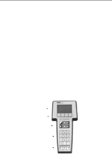
The HART (Highway Addressable Remote Transducer) Communicator (Figure 1-1) is a hand-held interface that provides a common communication link to all HART-compatible, microprocessor-based instruments.
Section 1 discusses the HART Communicator Connections, Liquid Crystal Display, Keypad, Offline and Online menu, Battery Pack, Memory Module, data pack 100, Maintenance, and Year 2000 Compatibility. It also includes short overviews on some of the Communicator’s functionality.
Section 2 describes tasks that are common to Fisher-Rosemount’s HART devices and includes some of the common screen displays.
Section 3 displays typical examples of menu trees specific to FisherRosemount products.
Your HART Communicator interfaces with any HART-compatible device from any wiring termination point using a 4–20 mA loop, provided a minimum load resistance of 250 ohms is present between the Communicator and the power supply. Your HART Communicator uses the Bell 202 frequency shift key (FSK) technique of high-frequency digital signals superimposed on a standard transmitter current loop of 4–20 mA. Because the total highfrequency signal voltage added to the loop amounts to zero, communication to and from a HART-compatible device does not disturb the 4–20 mA signal.
LIQUID CRYSTAL DISPLAY (LCD) 
FUNCTION KEYS 
ACTION KEYS 
ALPHANUMERIC KEYS 
SHIFT KEYS
FIGURE 1-1. The HART Communicator.
1-1

HART COMMUNICATOR CONNECTIONS
The HART Communicator can interface with a transmitter from the control room, the instrument site, or any wiring termination point in the loop through the rear connection panel (Figure 1-2).
To interface, connect the HART Communicator with the appropriate connectors in parallel with the instrument or load resistor. All connections are non-polarized. When connecting to a PC, you must use the PC Communication Adapter to connect to the Communicator’s serial port. See
Listen for PC Menu on page 1-26 for more information and Appendix B for a complete list of parts.
For intrinsically safe Canadian Standards Association (CSA) and Factory Mutual (FM) wiring connections, see Appendix C.

 !
!  WARNING
Explosions can result in death or serious injury. Do not connect to the serial port or NiCad recharger jack in an explosive atmosphere.
Loop Connectors
Serial Port
Optional NiCad
Recharger Jack
FIGURE 1-2. Rear Connection Panel with NiCad Recharger Jack.
1-2
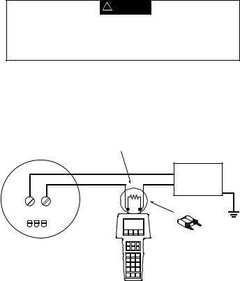
NOTE: For the HART Communicator to function properly, a minimum of 250 ohms resistance must be present in the loop. The HART Communicator does not measure loop current directly.
Figure 1-3 and Figure 1-4 illustrate typical wiring connections between the HART Communicator and any compatible device.
HART-compatible |
|
|
|
|
|
Device |
|
|
|
|
|
|
+ |
RL≥ 250 Ω |
_ |
|
+ |
|
|
|
|
||
|
_ |
+ |
|
|
+ |
+ |
_ |
mA |
|
|
|
|
|
Power |
|||
|
|
|
|
|
|
|
|
|
|
|
Supply |
|
|
_ |
+ |
_ |
_ |
|
|
|
|
|
Current
Meter
FIGURE 1-3. Connecting to the Transmitter Comm Terminals.
Device |
+ |
RL≥ 250 Ω |
_ |
|
+ |
|
|
||||
|
_ |
+ |
|
|
+ |
|
|
|
|
||
+ |
_ |
mA |
|
|
Power |
|
|
|
|||
|
|
|
|
Supply |
|
|
|
|
|
|
|
|
|
_ |
+ |
_ |
_ |
|
|
|
|
|
|
|
|
Current |
|
|
|
|
|
Meter |
|
|
|
FIGURE 1-4. Connecting the HART Communicator to the Loop.
1-3

 !
!  WARNING
Explosions can result in death or serious injury. Before connecting the HART Communicator in an explosive atmosphere, make sure the instruments in the loop are installed in accordance with intrinsically safe or nonincendive field wiring practices. For intrinsically safe CSA and FM wiring connections, see Appendix C.
Figure 1-5 shows how to connect the optional 250 ohm load resistor.
NOTE: To temporarily install the optional 250 ohm Load Resistor:
1.Insert the load resistor into the lead set jacks.
2.Open the loop to allow connection of the resistor in series in the loop.
3.Close the loop using the lead set connectors.
|
|
+ |
|
|
Power |
|
|
Supply |
|
|
– |
+ |
– |
|
HART-compatible Device |
Optional 250 Ohm |
|
|
|
Load Resistor |
275-0068A, 0275 B01A
FIGURE 1-5. Connecting the HART Communicator with the Load Resistor.
1-4

LIQUID CRYSTAL DISPLAY (LCD)
The LCD is an 8-line by 21-character display that provides communication between you and the connected device. When you connect to a HARTcompatible device, the top line of each Online menu displays the model name of the device and its tag. The bottom line of each menu is reserved for the dynamic labels for each software-defined function key, F1-F4 (found directly below the display).
These dynamic labels display available functions. For example, the label HELP appears above the F1 key when access to online help is available. See Software-Defined Function Keys on page 1-6 for more information.
The Communicator does not store key strokes in its memory. The LCD should be fully displayed before you press a key to do the next action.
THE ACTION KEYS
The action keys (Figure 1-1) are the six blue, white, and black keys located above the alphanumeric keys. The function of each key is described as follows:
On/Off Key
Use this key to power up and power off the HART Communicator. When you power up the Communicator, it automatically searches for
a HART-compatible device on the 4-20 mA loop. If a device is not found, the Communicator displays the message “No Device Found. Press OK....” Press the OK ‘F4’ function key and the Main menu displays on the screen. See
Main Menu on page 1-12.
If a HART-compatible device is found, the Communicator displays the Online menu. See Online Menu on page 1-19.
Refer to Getting to Know the HART Communicator on page 1-9,
Section 3, or your device-specific manual for more information about Online menu options.
You can select the Polling option to direct the HART Communicator to look for devices at multidrop addresses. See Polling Menu on page 1-23 for details.
During certain operations, the message “OFF KEY DISABLED” indicates that you cannot turn the HART Communicator off. This feature helps you avoid unintentionally turning off the power to the HART Communicator while the output of a device is fixed or when you are editing a device variable.
1-5
Up Arrow Key
Use this key to move the cursor up through a menu or list of options. You can also use it to scroll through lists of available characters
when editing fields that accept both alpha and numeric data.
Down Arrow Key
Use this key to move the cursor down through a menu or list of options. You can also use it to scroll through lists of available
characters when editing fields that accept alpha and numeric data.
Left Arrow and Previous Menu Key
Use this dual-function key to move the cursor to the left or back to the previous menu.
Right Arrow and Select Key
Use this dual-function key to move the cursor to the right or to select a menu option.
Hot Key
Use this key to quickly access important, user-defined options when  connected to a HART-compatible device. When the HART Communicator is turned off, press the Hot Key to automatically power up and display your predefined Hot Key menu. When powered up online, press the Hot Key to immediately display the Hot Key menu.
See Using the Hot Key on page 1-30 for more information.
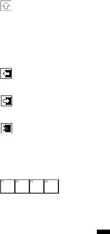
SOFTWARE-DEFINED FUNCTION KEYS
Use the four software-defined function keys located below the LCD, marked F1 through F4, to perform software functions as indicated by the dynamic labels. On any menu, the label appearing above a function key indicates the function of that key for the current menu. As you move among menus, different function key labels appear over these four keys. For example, in menus providing access to online help, the HELP label appears above the F1 key.
1-6

In menus providing access to the Home menu, the HOME label appears above the F3 key. When the HOME label displays, press F3 to return directly to the Online menu. Press BACK (F3) to return to the screen from which HOME was pressed.
Table 1-1 describes the labels that appear above each function key throughout the various Communicator menus.
F1
HELP Access online help
RETRY
Try to re-establish communication
EXIT Leave the current
menu
YES Answer yes/no
question
ALL Include current Hot Key item on Hot Key menu for
all devices
NEXT
Go to the next variable in offline edit
FILTR
Open customization menu to sort configurations
|
TABLE 1-1. Function Key Labels. |
|
|
||
|
|
|
|
|
|
|
F2 |
|
F3 |
|
F4 |
|
|
|
|
|
|
|
ON/OFF |
|
|
|
OK |
|
Activate or |
|
ABORT |
|
|
|
|
|
Acknowledge |
||
|
deactivate |
|
Terminate current |
|
|
|
|
|
information on |
||
|
a bit-enumerated |
|
task |
|
|
|
|
|
screen |
||
|
binary variable |
|
|
|
|
|
|
|
|
|
|
|
|
|
|
|
|
|
DEL |
|
ESC |
|
ENTER |
|
Delete current |
|
|
||
|
|
Leave a value |
|
Accept user- |
|
|
character or Hot |
|
|
||
|
|
unchanged |
|
entered data |
|
|
Key menu item |
|
|
||
|
|
|
|
|
|
|
|
|
|
|
|
|
|
|
QUIT |
|
|
|
SEND |
|
Terminate session |
|
EXIT |
|
Send configuration |
|
because of a |
|
Leave the current |
|
data to device |
|
communication |
|
menu |
|
|
|
error |
|
|
|
|
|
|
|
|
|
PGUP |
|
PGDN |
|
NO |
|
Move up one help |
|
Move down one |
|
Answer yes/no |
|
screen |
|
help screen |
|
question |
|
|
|
|
|
|
|
PREV |
|
NEXT |
|
ONE |
|
Go to previous |
|
Go to next message |
|
Include Hot Key |
|
message in a list of |
|
in a list of |
|
item for one device |
|
messages |
|
messages |
|
|
|
|
|
|
|
|
|
SAVE |
|
HOME |
|
|
|
Save information to |
|
Go to the top menu |
|
|
|
Memory Module or |
|
in the device |
|
|
|
data pack |
|
description |
|
|
|
|
|
|
|
|
|
MARK |
|
|
|
|
|
Toggle marked |
|
BACK |
|
|
|
configuration |
|
Go back to the |
|
|
|
variables for |
|
menu from which |
|
|
|
sending to a field |
|
HOME was pressed |
|
|
|
device |
|
|
|
|
|
|
|
|
|
|
|
XPAND |
|
|
|
|
|
Open detailed |
|
EDIT |
|
|
|
configuration |
|
Edit a variable value |
|
|
|
information |
|
|
|
|
|
|
|
|
|
|
|
CMPRS |
|
ADD |
|
|
|
Close detailed |
|
|
|
|
|
|
Add current item to |
|
|
|
|
configuration |
|
|
|
|
|
|
Hot Key menu |
|
|
|
|
information |
|
|
|
|
|
|
|
|
|
|
|
|
|
|
|
|
1-7
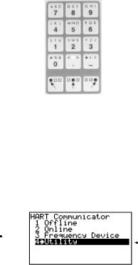
ALPHANUMERIC AND SHIFT KEYS
The 12 alphanumeric keys (Figure 1-6) perform two functions — the fast selection of menu options and data entry. Three shift keys enable use of the upper row of characters on each alphanumeric key.
FIGURE 1-6. HART Communicator Alphanumeric and Shift Keys.
Using the Fast Select Feature
From within any menu, you can select available options in two ways: 1) you can use the up and down arrow keys and the select key to access available options, 2) you can use the fast select feature. To fast select the desired option, press the corresponding number on the alphanumeric keypad. Figure 1-7 shows how to quickly access the Utility menu from the Main menu by pressing the indicated fast key.
Press this |
|
|
J K L |
|
|
To fast select |
key |
4 |
|
|
|||
|
|
this menu |
||||
|
|
|
|
|
|
|
|
|
|
|
|
|
choice |
FIGURE 1-7. Quickly Accessing Menus.
1-8

Using Shift Keys for Data Entry
Some menus require data entry. Use the up and down arrow keys when available, or use the alphanumeric and shift keys to enter the alphanumeric information into the HART Communicator.
If you press only the alphanumeric key within an edit menu, only the bold character in the center of the key will display. These large characters include the numbers zero through nine, the decimal point (.), and the dash
symbol (-). To enter the other characters on the keys, first press and release the shift key corresponding to the position of the desired character on the key and then press the alphanumeric key. Do not press the keys simultaneously. For example, to enter the letter “R” press the following key sequence:
|
|
|
→ |
|
|
|
|
|
P Q R |
|
|
|
|
6 |
|
|
|
|
|
Press the right shift key to activate the shift function; the right shift arrow icon appears in the upper right corner of the display. With right shift activated, press the 6 key; an “R” appears in the editable field. Press the shift key again to deactivate the shift function.
GETTING TO KNOW THE HART COMMUNICATOR
The HART Communicator is generally used in two environments — offline (not connected to a device) and online (connected to a device). The first menu displayed when you power up the Communicator is different for offline and online.
Powering up the Communicator when it is not connected to a device displays the message “No Device Found.” Press OK and the Main menu appears. Powering up the Communicator when it is connected to a device displays the Online menu for the device. From the Online menu, you can access the Main menu by pressing the left-arrow key. See Figure 1-8.
1-9

Power
Supply
|
5ø |
|
12.øø |
|
1øøø |
Main Menu |
Online Menu |
FIGURE 1-8. Powering Up Offline or Online.
Software Icons
The HART Communicator menus display icons that represent specific keys on the keypad. Figure 1-9 shows examples of these.
HART communication: Blinking  indicates ongoing communications (HART messages are presently being transmitted or received). Blinking
  indicates the device is configured in the burst mode.
|
|
|
Indicates shift is active |
|||||||
|
|
|
|
|
|
|
|
|
|
|
|
|
|
|
|
|
Low battery |
||||
|
|
|
|
|
||||||
|
|
|
|
|
|
|
|
|
|
|
|
|
|
|
|
|
|
|
|
Access |
|
|
|
|
|
|
|
|
|
|
previous |
|
Access additional |
|
|
|
|||||||
|
|
|
|
|
|
menu |
||||
|
|
|
|
|
|
|||||
menu items |
|
|
|
|
|
|
|
|
||
HOME
Access highlighted menu item
FIGURE 1-9. Menu Icons and Associated Keys.
1-10
Learning the Menu Structure
The following steps show you how to power up the Communicator offline, move through the menu structure, and then turn off the Communicator:
Turn the HART Communicator on.
Access the Utility menu by pressing  three times and then pressing
Access the Configure
Communicator menu from the Utility menu by pressing 


Access the Contrast menu by pressing  once and then pressing
Press ESC (F3) to return to the
Configure Communicator menu.
Press |
|
|
|
two times to return to the Main menu. |
|
|
|
|
|
|
|
|
|
|
Turn the HART Communicator off. 


1-11
Reviewing Installed Devices
The HART Communicator Memory Module contains device descriptions for specific HART-compatible devices. These descriptions enable the Communicator to recognize particular devices. The device types can be found in the Offline menu under New Configurations.
If you cannot find a specific HART-compatible device on your Communicator, the device revision you are looking for is not programmed into the Memory Module. In this instance, you are limited to what is available using the generic interface built into your HART Communicator.
To review the device descriptions programmed into your HART Communicator:
1. |
From the Main menu, press |
STU |
|
to access Offline menu. |
|
1 |
|
||||
|
|
|
|
|
|
|
|
|
STU |
|
|
2. |
From the Offline menu, press |
|
1 |
|
to access the list of device |
descriptions programmed into your HART Communicator. The Manufacturer menu displays a list of each manufacturer with device descriptions currently installed in your Communicator’s Memory Module. The standard 12 MB Memory Module is recommended, as it allows for more device descriptions.
3.Select a manufacturer, and the Model menu displays, containing a list of currently installed device models provided by the selected manufacturer.
4.Review the different manufacturers and models to determine the installed HART-compatible devices in your Communicator.
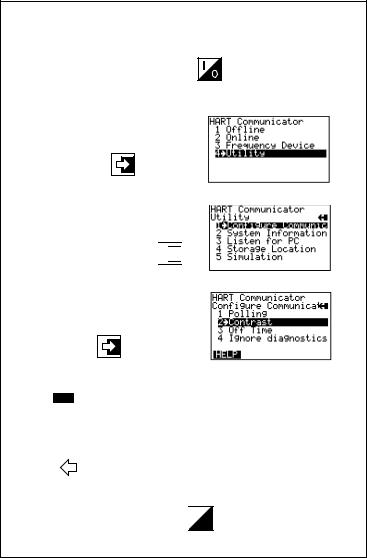
MAIN MENU
If the HART Communicator is powered up when it is not connected to a device, the first menu to appear after the “Device Not Found” message is the Main menu (Figure 1-10).
FIGURE 1-10. Main Menu.
1-12
If the Communicator is powered up when it is connected to a device, you can access the Main menu by pressing the previous menu key. Depending on the current online menu, you may need to press the previous menu key
several times or the HOME key plus 


 to return to the Main menu.
OFFLINE MENU
From the Main menu, press 1 to access the Offline menu. From the Offline menu you can access the options: New Configuration and Saved Configuration. Figure 1-11 shows a menu tree for the Offline functions.
A HART-compatible device does not have to be connected to use the offline options, except when sending saved configuration data to a connected device.
Offline Menu
1.New Config
2.Saved Config
Saved Configuration
1Module
2data pack
3PC
Name
Saved Configuration
1Edit
2Copy to...
3Send
4Print
5Delete
6Rename
7Compare
|
|
|
|
|
|
|
|
|
Edit |
|
|
|
|
|
|
|
|
1 |
Mark All |
|
|
Edit |
|
|||
2 |
Unmark All |
|
Configuration |
|
||||
3 |
Edit individually |
|
|
|||||
|
Variables |
|
||||||
4 |
Save As... |
|
|
|||||
|
|
|
|
|
|
|
|
|
|
|
|
|
|
|
Save as... |
|
|
|
|
|
|
|
|
|
||
|
|
|
|
|
|
1 |
Location |
|
|
Data Type |
|
|
|
||||
|
|
|
2 |
Name |
|
|||
|
1 |
Standard |
|
|
|
|||
|
|
|
3 |
Data Type |
|
|||
|
2 |
Partial |
|
|
|
|||
|
|
|
|
|
|
|||
|
3 |
Full |
|
|
|
|
|
|
|
|
|
|
|
|
|
|
|
Manufacturer
Listing
Model ID
Listing
Field Device Rev
Listing
From Blank Template
1Mark All
2Unmark All
3Edit individually
4Save As...
Location
1Module
2data pack
FIGURE 1-11. Offline Menu Tree.
1-13
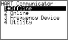
New Configuration (Offline)
Use this option to compile a custom set of device configuration data for downloading to any HART-compatible device. You can download repeatedly to multiple devices so that they store identical configuration data.
Offline configuration may not be available for all devices. Steps 2 and 3 below will help you verify if the desired manufacturer and device model are programmed into the Communicator’s Memory Module.
STU
1. Press 1 on the Main menu to access the Offline menu. This menu
allows you to enter a new device configuration or edit a saved device configuration.
To enter a new configuration, go to Step 2.
To edit a saved configuration, press 2 and go to Saved Configuration Menu (Offline) on page 1-17.
FIGURE 1-12. Offline Menu.
2.From the Offline menu, press 1. The Manufacturer menu displays a list of manufacturers with device descriptions currently installed in your HART Communicator.
3.Select a manufacturer; the Model menu displays. The Model menu contains a list of the currently installed device models provided by the manufacturer.
4.Select a device model for configuration; the Field Device Revision (Fld dev rev) menu displays. The Fld dev rev menu contains the currently installed software revisions for the field device and device descriptions (DD) for the model you selected from the previous screen.
5.Select a device revision; the From Blank Template menu (Figure 1-13) displays.
If you are unsure of the device revision, connect the HART Communicator to the device and determine its device revision level. You can access this information from the Online menu>Device Setup>Detailed Setup>Device Information. See your device manual for more information.
1-14
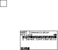
From Blank Template Menu
To access From Blank Template Menu, see steps 2 through 5 under New Configuration (Offline) on page 1-14.
FIGURE 1-13. From Blank Template Menu.
The following options are available from the From Blank Template menu:
Mark all flags all configurable variables to be sent to a HART-compatible device. Configuration variables are those that appear when you edit variables in the configuration using the Edit Individually option.
Unmark all removes the flags from all configurable variables in the configuration. Unmarked configuration variables are not sent to a connected HART-compatible device.
Edit individually (Figure 1-14) opens the Edit Individually menu containing numerous configuration variables.
FIGURE 1-14. Edit Individually Menu.
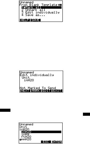
For example, to change the engineering units from inH20 to ftH20, find the configuration variable, press the Edit function key, highlight the new unit, and press the ENTER function key. The Esc key returns you to the previous
screen as displayed in Figure 1-15. When you are done, press the EXIT function key to return to the From Blank Template menu.
FIGURE 1-15. Unit Variable Menu.
1-15
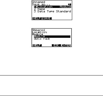
Save as... saves your new configuration to either the Memory Module or the data pack 100. See Figure 1-16 and Figure 1-17. The Memory Module holds up to 10 typical configurations, and contains the operating system software, and device application software in nonvolatile memory. The data pack stores up to 100 typical configurations in nonvolatile removable memory.
FIGURE 1-16. Save As... Menu.
FIGURE 1-17. Location Menu.
You can also use the Save As... menu to enter or edit the configuration name and data type. Data Type Standard provides a Data Type menu with editable options. Standard is the set of editable variables used when defining a new device configuration. Partial is a set of marked variables. Full is the set of all device variables.
NOTE: Configurations created offline in the HART Communicator will not transfer to Asset Management Solutions (AMS) software; however, ‘Full’ configurations saved from a field device to a HART Communicator may be uploaded to AMS. Configurations saved as ‘Full’ from an online device may also be transferred directly to AMS.
After you have made all desired changes, save your new configuration to a storage location and return to the Offline menu. Refer to Storage Location Menu on page 1-28 for more information.
1-16

Saved Configuration Menu (Offline)
You can access configuration data already stored in your Communicator through the offline Saved Configuration menu.
To access configuration data stored in your HART Communicator:
1.Press 1 on the Main menu to access the Offline menu.
2.Press 2 from the Offline menu, and the Saved Configuration menu screen displays (Figure 1-18).
FIGURE 1-18. Saved Configuration Menu (Offline).
3.Select either Module Contents or data pack Contents, as appropriate, to open your stored configurations. Both storage locations list all saved configurations by assigned Tag. See Xpand on page 1-18 for more configuration identification details.
The PC option is not operational with this release. Refer to Listen for PC Menu on page 1-26 for details on interfacing with a PC.
Data Pack Contents Menu
Figure 1-19 shows the data pack Contents menu, displaying a listing of device configurations stored in the data pack. From the Saved Configuration menu (Figure 1-18), press 2 to access the data pack Contents menu.
FIGURE 1-19. Data Pack Contents Menu.
The following functions keys are available from the data pack Contents menu:
The FILTR function key opens a menu that provides Sort and Filter options for customizing your view of saved device configurations. Sort lets you group and display device configurations according to your choice of Tag, Descriptor, or Name. Tag Filter lets you view information according to what
1-17
you entered with Sort by picking characters from the device Tag, Descriptor, or Name.
When setting up a filter, you can use the period (.) to replace a single character of any value or the asterisk (*) to replace zero or more alphanumeric characters of any value.
For example, if you enter A-*-.1, it should match all device tags starting with A-, followed by any characters, followed by -, followed by any single character, and ending with a 1. That means only devices starting with A- and ending in 1, out of your list of saved device configurations, will display as a group on the Communicator’s screen.
The XPAND function key allows you to view the Tag, Descriptor, and Name for the current configuration. Select Compress to return to the previous compressed screen with the current Tag or Descriptor or Name.
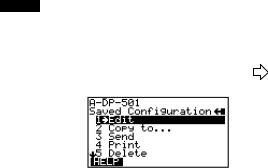
Saved Configuration Menu (data pack Contents) |
|
|
|
From the data pack Contents menu (Figure 1-19), press |
|
|
to open the |
Saved Configuration menu (Figure 1-20). |
|
|
|
|
|
|
|
FIGURE 1-20. Saved Configuration Menu (data pack Contents).
The following functions are available from the Saved configuration menu:
Edit displays the Edit menu. These edit functions are the same as described under Edit individually on page 1-15. If you are editing online, remember that only stored data can be edited. A Partial configuration can be edited, but you must convert it to a Standard configuration in order to save your edits.
Copy to... specifies the storage location where you want the copy to be stored. You can also change the configuration name when using this option.
Send sends your saved configuration to a connected device.
Print requires AMS running in your computer. This option is intended for the future. See Listen for PC Menu on page 1-26 for more information.
Delete removes a saved configuration from the memory storage location. A confirmation message will appear. Press Yes or No to complete the function.
1-18
Rename accesses the Configuration Name editing menu. After making name changes, enter and save the data to return to the previous storage location menu.
Compare compares a selected device configuration from a stored location with another device configuration. The HART Communicator compares device types, variables, marked lists, etc. Messages will appear indicating whether the configurations compared are the same or different. Press OK to return to the storage location and your list of device configurations. Find and make any necessary changes resulting from your comparisons.
In order to produce a “Same / Differ” result, the following conditions must be met when comparing two configurations:
1.Device type (including manufacturer), device type number, device revision, and DD revision must match exactly.
2.Configurations can only be compared against other configurations containing the same set of variables. The Communicator will notify you if this condition is not met.
3.The format of data storage must match exactly. The Communicator will notify you if this condition is not met.
User assigned configuration names are not considered, as they will differ.
ONLINE MENU
VWX
With a HART-compatible device connected, press 2 on the Main menu to access the Online menu (Figure 1-21).
5ø
12.øøø
FIGURE 1-21. Online Menu.
The Online menu displays the name of the device on the first line of the LCD. You have complete functionality for a specific device only when that device description is present in the HART Communicator. If the DD is not present in the HART Communicator, contact your nearest service representative.
The Online menu can be different depending on the connected device. See your device-specific manual for Online menu details. Or, see Section 3 for a selection of device-specific menu trees.
1-19

When the DD for a specific device is not available, your HART Communicator provides a generic interface. This generic interface enables you to perform functions common to all HART-compatible devices.
Figure 1-22 shows the Generic Online menu tree.
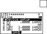
The Online (Generic) menu is the first menu in the generic interface. This menu displays critical, up-to-date device information such as the process variable (PV), analog output (AO), lower range value (LRV), and upper range value (URV). Configuration parameters for the connected device are accessed using the Device setup option.
The following functions are available from the Generic Online menu:
The SAVE function key allows you to save a configuration from a transmitted device. See Changing a Saved Configuration on page 1-29 for more details.
Device Setup accesses the Device Setup menu, containing configurable device parameters common to all HART-compatible devices.
PV (Primary Variable) displays the dynamic PV and the related engineering units. When the PV contains too many characters to display on the Online menu, press 1 to access the PV menu and view the PV and related engineering units.
AO (Analog Output) and related engineering units are displayed on the Online menu. The AO is the signal on the 4–20 mA scale that corresponds to the PV. When the analog output contains too many characters to display on the Online menu, press 3 to access the PV AO menu and view the AO output and related engineering units.
Current LRV (Lower Range Value) and related engineering units are displayed on the Online menu. When the LRV contains too many characters to display on the Online menu, press 4 to access the PV LRV menu and view the LRV and related engineering units.
Current URV (Upper Range Value) and the related engineering units are displayed on the Online menu. When the URV contains too many characters to display on the Online menu, press 5 to access the PV URV menu and view the URV and related engineering units.
1-20
Generic
Online Menu
1Device Setup
2PV
3AO
4LRV
5URV
1Process Variables
2Diagnostics and Service
3 Basic Setup
4 Detailed Setup
5 Review
1Present variable
2Percent Range
3Analog Output
|
|
|
|
|
|
|
|
|
|
|
|
|
|
1. Test Device |
|
|
Self Test |
|
|
|
|
|
|
|
|
|
2. Loop Test |
|
|
|
|
|
|
|
|
|
|
|
|
3. Calibration |
|
1. Apply Values |
|
|
|
|
|
|
|||
|
|
|
|
|
|
|
||||||
|
|
2. Enter Values |
|
|
|
|
|
|
||||
|
4. D/A Trim |
|
|
|
|
|
|
|
||||
|
|
|
|
|
|
|
|
|
|
|
|
|
|
|
|
|
|
|
|
|
|
|
|
|
|
|
|
|
|
|
|
|
|
|
|
|
|
|
|
1. Tag |
|
|
|
|
|
|
|
|
|
|
|
|
2. PV Snsr Unit |
|
|
|
|
|
|
|
|
|
|
|
|
3. Range Values |
|
1 Model |
|
|
|
|
|
|
|
||
|
|
|
2 Tag |
|
|
|
|
|
|
|
||
|
4. Device Info. |
|
3 Date |
|
|
|
|
|
|
|
||
|
|
4 Descriptor |
|
|
|
|
|
|
|
|||
|
|
|
|
|
|
|
|
|
|
|||
|
5. Xfer Fnctn |
|
5 Message |
|
|
|
|
|
|
|
||
|
|
6 PV snsr s/n |
|
|
1 Univ Rev. |
|
|
|
||||
|
|
|
7 Final Asmbly # |
|
|
|
|
|||||
|
|
|
|
|
2 Fld Dev Rev |
|
|
|
||||
|
6.PV Damp |
|
8 Revision |
|
|
|
|
|||||
|
|
|
|
3 Softw Rev |
|
|
|
|||||
|
|
|
|
|
|
|
|
|
|
|
||
|
|
|
1. Process Variables |
|
|
|
|
|
||||
|
1 Sensors |
|
|
|
|
|
|
|||||
|
|
2. PV Snsr Unit |
|
|
|
|
|
|||||
|
|
|
1 PV LSL |
|
|
|||||||
|
|
|
|
|
|
|||||||
|
|
|
|
|
|
|
|
|
|
|||
|
|
|
3. Sensor Info |
|
2 PV USL |
|
||||||
|
|
|
|
3 PV Min Span |
|
|||||||
|
|
|
|
|
|
|
|
|
|
|
|
|
|
|
|
1 PV Damp |
|
|
|
|
|
||||
|
|
|
2 PV URV |
|
|
|
|
|
||||
|
2 Signal |
|
3 PV LRV |
|
|
|
|
|
||||
|
Condition |
|
4 Xfer Fnctn |
|
|
|
|
|
||||
|
|
|
5 PV % Range |
|
|
|
|
|
||||
|
|
|
|
|
|
|
|
|
|
|
|
|
|
|
|
|
|
|
|
|
|
1 A/O 1 |
|
||
|
|
|
|
|
|
|
|
|
2 A/O Alarm Type |
|
||
|
|
|
1. Analog Output |
|
3 Loop Test |
|
||||||
|
|
|
|
4 D/A Trim |
|
|||||||
|
|
|
|
|
||||||||
|
3 Output |
|
|
|
|
|
|
|
5 Scaled D/A Trim |
|
||
|
|
|
|
|
|
|
|
|
||||
|
Condition |
|
|
|
|
|
|
|
|
|
|
|
|
|
|
2. HART Output |
|
1 Poll Address |
|||||||
|
|
|
|
|
|
|
|
|
2 Number of Request |
|||
|
|
|
|
|
|
|
|
|
Preambles |
|||
|
|
|
|
|
|
|
|
|
|
|
|
|
|
|
|
1 Model |
|
|
|
|
|
||||
|
|
|
2 Tag |
|
|
|
|
|
||||
|
|
|
3 Date |
|
|
|
|
|
||||
|
|
|
4 Descriptor |
|
|
|
|
|
||||
|
4 Device |
|
5 Message |
|
|
|
|
|
||||
|
Information |
|
6 PV Snsr S/N |
|
1 Univ Rev. |
|
||||||
|
|
|
7 Final Asmbly Num |
|
2 Fld Dev Rev |
|
||||||
|
|
|
8 Revision |
|
3 Softw Rev |
|
||||||
|
|
|
|
|
|
|
|
|
|
|
|
|
FIGURE 1-22. Generic Online Menu Tree.
1-21
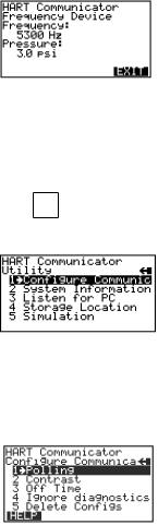
FREQUENCY DEVICE MENU
YZ /
From the Main menu, press 3 to access the Frequency Device menu (Figure 1-23). This menu displays the frequency output and corresponding pressure output for the current-to-pressure devices. The output shown below was taken from device Model 3311.
FIGURE 1-23. Frequency Device Menu.
UTILITY MENU |
J K L |
|
|
From the Main menu, press 4 to access the Utility menu (Figure 1-24). |
|
The Utility menu provides access to functions that affect only the operation of the HART Communicator.
FIGURE 1-24. Utility Menu.
Configure Communicator Menu
From the Utility menu, press 1 to access the Configure Communicator menu (Figure 1-25). Use this menu to set the polling, adjust the LCD contrast, set the Communicator off time, or set the number of ignore diagnostics messages.
FIGURE 1-25. Configure Communicator Menu.
1-22
Loading...