

PN: 00275-8026-0001
Product Discontinued
HART®Communicator
MAN 4275A00
English
July 2000

Product Manual for the
HART Communicator
NOTICE
Read this manual before working with this product. For personal and
system safety, and for optimum product performance, make sure you
thoroughly understand the contents before using or servicing this
product.
For equipment service needs, contact the nearest product
representative.
Rosemount andSMART FAMILY are registered trademarks of Rosemount Inc.
MINIGRABBER is a trademark of Pomona Electronics.
HART is a registered trademark of the HART Communication Foundation.
Fisher-Rosemount
8301 Cameron Road
Austin, TX 78754 USA
Technical Support: 1-800-833-8314
or (512) 832-3774
Service: 1-800-654-7768
www.hartcommunicator.com
MAN 4275A00 AW# 000701
© Fisher-Rosemount Systems, Inc. 2000.
All Rights Reserved.

TABLE OF CONTENTS
The HART®Communicator............................................... 1-1
Introduction........................................................................................ 1-1
HART Communicator Connections................................................... 1-2
Liquid Crystal Display (LCD)............................................................. 1-5
The Action Keys................................................................................ 1-5
On/Off Key ................................................................................ 1-5
Up Arrow Key............................................................................ 1-6
Down Arrow Key ....................................................................... 1-6
Left Arrow and Previous Menu Key........................................... 1-6
Right Arrow and Select Key ...................................................... 1-6
Hot Key ..................................................................................... 1-6
Software-Defined Function Keys....................................................... 1-6
Alphanumeric and Shift Keys............................................................ 1-8
Using the Fast Select Feature................................................... 1-8
Using Shift Keys for Data Entry................................................. 1-9
Getting to Know the HART Communicator........................................ 1-9
Software Icons ........................................................................ 1-10
Learning the Menu Structure................................................... 1-11
Reviewing Installed Devices ................................................... 1-12
Main Menu....................................................................................... 1-12
Offline Menu .................................................................................... 1-13
New Configuration (Offline)..................................................... 1-14
From Blank Template Menu............................................ 1-15
Saved Configuration Menu (Offline)........................................ 1-17
Data Pack Contents Menu.............................................. 1-17
Saved Configuration Men u (data pack Contents)........... 1-18
Online Menu .................................................................................... 1-19
Frequency Device Menu ................................................................. 1-22
Utility Menu...................................................................................... 1-22
Configure Communicator Menu .............................................. 1-22
Polling Menu ................................................................... 1-23
Contrast Menu................................................................. 1-24
Off Time Menu ................................................................ 1-24
Ignore Diagnostics Menu ................................................ 1-25
i

Delete Configs Menu....................................................... 1-25
System Information M enu ....................................................... 1-26
Listen for PC Menu ................................................................. 1-26
Storage Location Menu........................................................... 1-28
Simulation Menu ..................................................................... 1-28
Saving a Connected Device Configuration...................................... 1-29
Using the Hot Key ........................................................................... 1-30
Customizing the Hot Key Menu............................................... 1-31
Adding Options to the Hot Key Menu...................................... 1-31
Deleting Options from the Hot Key Menu................................ 1-33
The HART Communicat or and the Year 2000 ................................ 1-34
Editing the Date....................................................................... 1-34
Servicing the HART Communicator ................................................ 1-35
Calibrating the HART Communicator...................................... 1-35
Using a Battery Pack............................................................... 1-35
Changing Alkaline Batteries............................................ 1-36
Recharging the Battery Pack.......................................... 1-37
Using a Memory Module ......................................................... 1-37
Replacing the Memory Module ....................................... 1-38
Installing and Removing the Data Pack 100 ........................... 1-39
Common Tasks for Fisher-Rosemount HART
Devices ............................................................................. 2-1
Introduction........................................................................................ 2-1
Powering Up Online .......................................................................... 2-1
Online Menu ...................................................................................... 2-2
Device Setup............................................................................. 2-2
Primary Variable (PV) ............................................................... 2-3
Analog Output (AO)................................................................... 2-3
Lower Range Value (LRV) ........................................................ 2-3
Upper Range Value (URV)........................................................ 2-3
Device Setup Menu........................................................................... 2-4
Process Variables..................................................................... 2-4
Diag/Service.............................................................................. 2-4
Basic Setup............................................................................... 2-5
Detailed Setup........................................................................... 2-5
Review ...................................................................................... 2-6
Fast Key Sequences ......................................................................... 2-6
ii

Menu Trees....................................................................... 3-1
Introduction........................................................................................ 3-1
Model 54pH/ORP Transmitter ......................................................... 3-2
Model 333 HART® Tri-Loop Converter............................................ 3-3
Model 644 Temperature Transmitter................................................ 3-4
Model 1151 Pressure Transmitter.................................................... 3-5
Model 2081C Conductivity T ransmitter............................................ 3-6
Model 2081pH Transmitter............................................................... 3-7
Model 2088 Pressure Transmitter.................................................... 3-8
Model 2090 Pressure Transmitter.................................................... 3-9
Model 3001S Hydrostatic Transmitter............................................ 3-10
Model 3044C T emperature Transmitter......................................... 3-11
Model 3051 Pressure Transmitter.................................................. 3-12
Model 3051C Pressure Transmitter (Original)................................ 3-13
Model 3081C Conductivity T rans mitter.......................................... 3-14
Model 3081FG Oxygen Analyzer ................................................... 3-15
Model 3081pH Transmitter.............................................................. 3-16
Model 3095C Level Controller........................................................ 3-17
Model 3095MV Multivariable Transmitter....................................... 3-18
Model 3144 T emperature Transmitter............................................ 3-19
Model 3201 Hydrostatic Interface Unit........................................... 3-20
Model 3202 Smart Application Module........................................... 3-21
Model 3244 T emperature Transmitter............................................ 3-22
Model 3680 Density Transmitter .................................................... 3-23
Model 3809/3810 Variable Area Meter........................................... 3-24
Model 4000 Oxygen Analyzer........................................................ 3-25
Model 8712C Mag Flow Transmitter.............................................. 3-26
Model 8712C+ Mag Flow Transmitter............................................ 3-27
Model 8712U+ Mag Flow Transmitter............................................ 3-28
Model 8800 V ortex Flowmeter . ...................................................... 3-29
Model 9701 Mass Flowmeter......................................................... 3-30
Model 9712 Mass Flowmeter......................................................... 3-31
Model 9739 Mass Flowmeter......................................................... 3-32
iii

Model APEX Radar Level Gauge................................................... 3-33
Model ProBarTM DP Flowmeter .................................................... 3-34
Model ProBarTM UC Flowmeter .................................................... 3-35
Model Tri-20/9000 Oval Flowmeter................................................ 3-36
Model WC3000 Oxygen Analyzer .................................................. 3-37
HART Communicator Messages ...................................... A-1
Specifications and Ordering Information........................... B-1
Functional Specifications.................................................................. B-1
Performance Specifications.............................................................. B-2
Physical Specifications..................................................................... B-2
Ordering Information........................................................................ B-3
Spare Parts.............................................................................. B -4
CSA and FM Intrinsic Safety Approvals........................... C-1
Canadian Standards Asso ciation (CSA) .......................................... C-1
Factory Mutual (FM) ......................................................................... C-2
Troubleshooting Communication Problems..................... D-1
If you are still having problems......................................................... D-3
Index.................................................................................. I-1
iv

Section
LIST OF ILLUSTRATIONS
Figure Number Title Page
1-1. The HART Communicator. .......................................................... 1-1
1-2. Rear Connection P anel with NiCad Recharger Jack. ................. 1-2
1-3. Connecting to the Transmitter Comm Terminals. ....................... 1-3
1-4. Connecting the HART Communicator to the Loop. ..................... 1-3
1-5. Connecting the HART Communicator with the Load Resistor. ... 1-4
1-6. HART Communicator Alphanumeric and Shift Keys. .................. 1 -8
1-7. Quickly Accessing Menus. .......................................................... 1-8
1-8. Powering Up Offline or Online. .................................................. 1-10
1-9. Menu Icons and Associated Keys. ............................................ 1-10
1-10. Main Menu. ............................................................................... 1-12
1-11. Offline Menu Tree. .................................................................... 1-13
1-12. Offline Menu. ............................................................................. 1-14
1-13. From Blank Template Menu. ..................................................... 1-15
1-14. Edit Individually Menu. .............................................................. 1-15
1-15. Unit Variable Menu. ................................................................... 1-15
1-16. Save As... Menu. ....................................................................... 1-16
1-17. Location Menu. ......................................................................... 1-16
1-18. Saved Configuration Menu (Offline). ......................................... 1-17
1-19. Data Pack Contents Menu. ....................................................... 1-17
1-20. Saved Configuration Menu (data pack Contents). .................... 1-18
1-21. Online Menu. ............................................................................. 1-19
1-22. Generic Online Menu Tree. ....................................................... 1-21
1-23. Frequency Device Menu. .......................................................... 1-22
1-24. Utility Menu. .............................................................................. 1-22
1-25. Configure Communicator Menu. ............................................... 1-22
1-26. Polling Menu. ............................................................................ 1-23
1-27. Contrast Menu. .......................................................................... 1-24
1-28. Off Time Menu. ......................................................................... 1 -24
1-29. Ignore Diagnostics Menu. ......................................................... 1-25
ix

1-30. Delete Configurations Menu. ..................................................... 1-25
1-31. System Information Menu. ........................................................ 1-26
1-32. Listen for PC Menu. .................................................................. 1-26
1-33. Storage Location Menu. ............................................................ 1-28
1-34. Sample Hot Key Menu. ............................................................. 1-30
1-35. Hotkey Configuration Menu. ...................................................... 1-31
1-36. Adding a Hot Key Option. .......................................................... 1-32
1-37. Marking a Read-Only Hot Key Option. ...................................... 1-32
1-38. Hot Key Menu. .......................................................................... 1-32
1-39. Variable Display Option. ............................................................ 1-33
1-40. Deleting a Hot Key Option. ........................................................ 1-33
1-41. Date Menu. ............................................................................... 1-34
1-42. HART Communicator Exploded View. ...................................... 1-35
1-43. Battery Pack Removal. .............................................................. 1-36
1-44. Memory Module Replacement. ................................................. 1-38
1-45. Data Pack 100 Installation and Removal. ................................. 1-39
2-1. Online Menu. ............................................................................... 2-2
2-2. Device Setup Menu. .................................................................... 2-4
2-3. Diagnostics and Service Menu. ................................................... 2-4
2-4. Basic Setup Menu. ...................................................................... 2-5
2-5. Sample Fast Key Sequence. ....................................................... 2-6
LIST OF TABLES
Table Number Title Page
1-1. Function Key Labels. ................................................................... 1-7
1-2. Main Options for the PC AMS Interface.......................................1-27
x
SECTION 1
The HART
INTRODUCTION
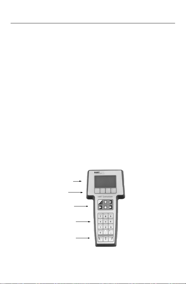
The HART (Highway Addressable Remote Transducer) Communicator
(Figure 1-1) is a hand-held interfacethat provides a common communication
link to all HART-compatible, microprocessor-based instruments.
Section 1 disc usses the HART Com municat o r Connections, Liquid Crystal
Display, Key pad, Offline and Online menu, Battery Pack, Memory Module,
data pack 100, Maintenance, and Year 2000 Compatibility.It also includes
short overviews on some of the Communicator’s functionality.
Section 2 desc ribes tasks that are common to Fisher- Rosemount’s HART
devices and includes some of the common screen dis plays.
Section 3 displays typical examples of menu trees specific to FisherRosemount products.
YourHART Communicator interfaces with any HART-compatible device from
any wiring termination point using a 4–20 mA loop, provided a minimum load
resistance of 250ohms is present between the Communicator and the power
supply.Your HART Communicator u ses the Bell 2 02 frequency shift key
(FSK) technique of high-frequency digital signals superimposed on a
standard transmitter current loop of 4–20 mA. Because the total highfrequency signal voltage added to the loop amounts to zero, communication
to and from a HART-compatible device does not disturb the 4–20 mA signal.
LIQUID CRYSTAL DISPLAY(LCD)
®
Communicator
FUNCTION KEYS
ACTION KEYS
ALPHANUMERIC KEYS
SHIFT KEYS
FIGURE 1-1. The HARTCommunicator.
1-1
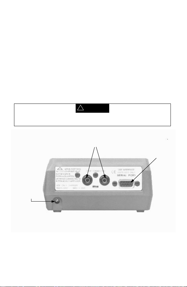
HART COMMUNICATOR CONNECTIONS
The HART Communicator can interface with a transmitter from the control
room, the instrument site, or any wiring termination point in the loop th rough
the rear connection panel (Figure 1-2).
To interface, connect t he HART Communicator with the appropriate
connectors in parallel wit h the instrument or load resistor. All connectionsare
non-polarized. When conne cting to a PC, you must use the PC
Communication Adapter to connect to t he Communicator’s serial port. See
Listen for PC Menu on page 1-26 for more information and Appendix B for
a complete list of parts.
For intrinsically safe Canadian Standards Association (CSA) and Factory
Mutual (FM) wiring connections, see A ppendix C.
!
WARNING
Explosions can result in death or serious injury. Do not connect to the serial port
or NiCad recharger jack in an explosive atmosphere.
Loop Connectors
Serial Port
Optional NiCad
Recharger Jack
FIGURE 1-2. Rear Connection Panel with NiCad Recharger Jack.
1-2
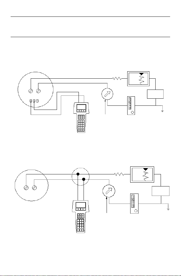
NOTE: For the HART Communicator to function properly, a minimum of 250
ohms resistance must be present in the loop. The HART Communicator
does not measure loop current directly.
Figure 1-3 and Figure 1-4 illustrate typical wiring connections between the
HART Communicator and any compatible device.
HART-compatible
Device
+
RL≥250 Ω
_
+
Device
+
_
_
+
_
Current
Meter
mA+
_
+
FIGURE 1-3. Connecting to the Transmitter Comm Terminals.
+
_
_
R
Current
Meter
≥250 Ω
L
+
_
mA
_
_
+
FIGURE 1-4. Connecting the HART Communicator to the Loop.
Power
Supply
+
Power
Supply
+
_
+
_
1-3
!
WARNING
Explosions can result in death or serious injury. Before connecting the HART
Communicator in an explosive atmosphere, make sure the instruments in the
loop are installed in accordance with intrinsically safe or nonincendive field
wiring practices. For intrinsically safe CSA and FM wiring connections, see
Appendix C.
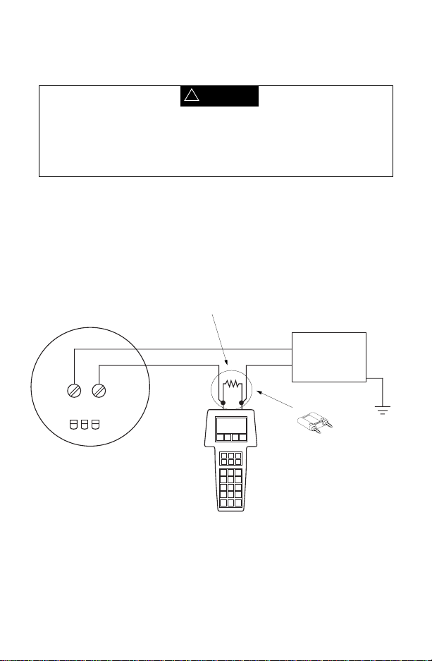
Figure 1-5 shows how to connect the optional 250 ohm load resistor.
NOTE: To temporarily install the optional 250 ohm Load Resistor:
1. Insert the load resistor into the lead set jacks.
2. Open the loop to allow connection of the resistor in series in the loop.
3. Close the loop using the lead set connectors.
+
Power
Supply
–
–
+
HART-compatible Device
Optional 250 Ohm
Load Resistor
FIGURE 1-5. Connecting the HART Communicator with the Load Resistor.
1-4
275-0068A, 0275 B01A

LIQUID CRYSTAL DISPLAY (LCD)
The LCD is an 8-line by 21-character display that provides communication
between you and the connected device. When you connect to a HARTcompatible device, the top line of each Online menu displays the model
name of the device and its tag. The bottom line of each menu is reserved for
the dynamic labels for each software-defined function key, F1-F4 (found
directly below the display).
These dynamic labels display available functions. For example, the label
appears above the F1 key when access to online help is available.
HELP
See Software-Defined Function Keys on page 1-6 for more informa tion.
The Communicator does not store key strokes in its memory. The LCD
should be fully displayed before you press a key to do the next action.
THE ACTION KEYS
Theactionkeys(Figure 1-1) are the six blue, white, and black keys located
above the alphanumeric keys. The function of each key is described as
follows:
On/Off Key
Use this key to power up and power off the HART Communicator.
When you power up the Communicator,it automatically searches for
a HART-compatible device on the 4-20 mA loop. If a device is not found, the
Communicator displays the message “No Device Found. Press OK....” Press
the OK ‘F4’ function key and the Main menu displays on the screen. See
Main Menu on page 1-12.
If a HART-compatible device is found, the Communicator displays the Online
menu. See Online Menu on page 1-19.
Refer to Getting to Know the HART Communicator on page 1-9,
Section 3, or your device-specificmanual for more informationabout Online
menu options.
You can select the Polling option to direct the HART Communicator to look
for devices at multidrop addresses. See Polling Menu on page 1-23 for
details.
During certain operations, the message “OFF KEY DISABLED” indicates
that you cannot turn the HART Communicator off. This feature helps you
avoid unintentionally turning off the power to the HART Communicator while
the output of a device is fixed or when you are editing a device variable.
1-5
Up Arrow Key
Use this key to move the cursor up through a menu or list of options.
You can also use it to scroll through lists of available characters
when editing fields that accept both alpha and numeric data.
Down Arrow Key
Use this key to move the cursor down through a menu or list of
options. You can also use it to scroll through lists of available
characters when editing fields that accept alpha and numeric data.
Left Arrow and Previous Menu Key
Use this dual-function key to move the cursor t o the left or back
to the previous menu.
Right Arrow and Select Key
Use this dual-function key to move the cursor to the right or to select
a menu option.
Hot Key
Use this key to quickly access important, user-defined options when
connected to a HART-compatible device. When the HART
Communicator is turned off,press the Hot Key to automaticallypower up and
display your predefined Hot Key menu. When powered up online, press the
Hot Key to immediately display the Hot Key menu.
See Using the Hot Key on page 1-30 for more information.
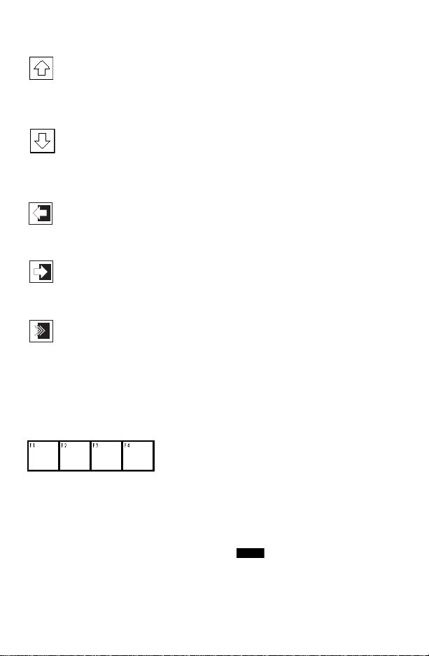
SOFTWARE-DEFINED FUNCTION KEYS
Use the four software-defined function keys located below the LCD, marked
F1 through F4, to perform software functions as indicated by the dynamic
labels. On any menu, the label appearing above a function key indicates the
function of that key for the current menu. As you move among menus,
different function key labels appear over these four keys. For example, in
menus providing access toonline help, the label appears abovethe F1
key.
HELP
1-6

In menus providing access to the Home menu, t h e label appears
above the F3 key. When the label displays, press F3 to return directly
to the Online menu. Press (F3) to return t o the screen from which
was pressed.
HOME
HOME
BACK
HOME
Table 1-1 describes the labels that appear above each function key
throughout the various Communicator menus.
TABLE 1-1. Function Key Labels.
F1 F2 F3 F4
HELP
Access online
help
RETRY
Tryto re-establish
communication
EXIT
Leave the current
menu
YES
Answer yes/no
question
ALL
Include current
Hot Key item on
Hot Key menu for
all devices
NEXT
Go to the next
variable in offline
edit
FILTR
Open
customization
menu to sort
configurations
ON/OFF
Activate or
deactivate
a bit-enumerated
binary variable
DEL
Delete current
character or Hot
Key menu item
SEND
Send configuration
data to device
PGUP
Move up one help
screen
PREV
Go to previous
message in a list of
messages
SAVE
Save information to
Memory Module or
data pack
MARK
Togglemarked
configuration
variables for
sending to a field
device
XPAND
Open detailed
configuration
information
CMPRS
Close detailed
configuration
information
ABORT
Terminate current
task
ESC
Leave a value
unchanged
QUIT
Terminate session
because of a
communication
error
PGDN
Move down one
help screen
NEXT
Go to next message
in a list of
messages
HOME
Go to the top menu
in the device
description
BACK
Go back to the
menu from which
HOME was pressed
EDIT
Edit a variable value
ADD
Add current item to
Hot Key menu
OK
Acknowledge
information on
screen
ENTER
Accept userentered data
EXIT
Leave the current
menu
NO
Answer yes/no
question
ONE
Include Hot Key
item for one device
1-7
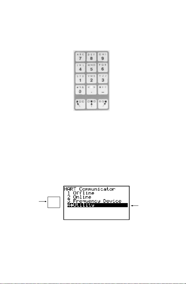
ALPHANUMERIC AND SHIFT KEYS
The 12 alphanumeric keys (Figure 1-6) perform two functions — the fa st
selection of menu options and data entry. Three shift keys enable use of the
upper row of characters on each alphanumeric key.
FIGURE 1-6. HART Communicator Alphanumeric and Shift Keys.
Using the Fast Select Feature
From within any menu, you can select available options in two ways: 1) you
can use the up and down arrow keys and the select key to access available
options, 2) you can use the fast select feature. To f ast select the desired
option, press the corresponding number on the alphanumeric ke ypad.
Figure 1-7 shows how to quickly access the Utility menu from the Main
menu by pressing the indicated fast key.
Press this
key
JKL
4
FIGURE 1-7. Quickly Accessing Menus.
1-8
To fast select
this menu
choice

Using Shift Keys for Data Entry
Some menus require data entry. Use the up and down arrow keys when
available, or use the alphanumeric and shift keys to enter the alphanumeric
information into the HART Communicator.
If you press only the alphanumeric key within an edit menu, only t he bold
character in the center of the key will display. These large characters include
the numbers zero through nine, the decimal point (.), and the dash
symbol (-). To enter the other characters on the keys, first press and release
the shift key corresponding to the position of the desired character on the key
and then press the alphanumeric key.Do not press the keys simultaneously.
For example, to enter the letter “R” press the following key sequence:
PQR
→
6
Press the right shift key to activate the shift function; the right shift arrow icon
appears in the upper right corner of the display. With right shift activated,
press the 6 key; an “R” appears in the editable field. Press the shift key again
to deactivate the shift function.
GETTING TO KNOW THE HART COMMUNICATOR
The HART Communicator is generally used in two environments — offline
(not connected to a device) and online (connected to a device). The first
menu displayed when you power up the Communicator is different for offline
and online.
Powering up the Communicator when itis not connected to a device displays
the message “No Device Found.” Press OK and the Main menu appears.
Powering up the Communicator when itis connected to a device displays the
Online menu for the device.From the Online menu, you can access the Main
menu by pressing the left-arrow key. See Figure 1-8.
1-9
5ø
1øø
Power
Supply
12.øø
ø
Main Menu
Online Menu
FIGURE 1-8. Powering Up Offline or Online.
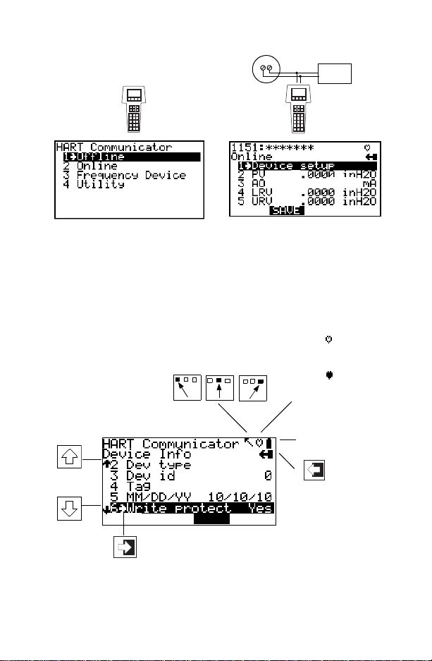
Software Icons
The HART Communicator menus display icons that represent specific keys
on the keypad. Figure 1-9 shows examples of these.
HART communication:
Blinking indicates ongoing
communications (HART
messagesarepresentlybeing
transmitted or received).
Blinking indicates the
device is configured in the
burst mode.
Indicates shift is active
Low battery
Access
Access additional
menu items
Access highlighted
menu item
HOME
FIGURE 1-9. Menu Icons and Associated Keys.
1-10
previous
menu
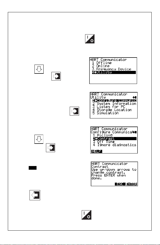
Learning the Menu Structure
The following steps show you how to power up the Communicator offline,
move through the menu structure, and then turn off the Communicator:
➊ Turn the HART Communicat o r on.
➋ Access the Utility menu by
pressing three times
and then pressing
➌ Access the Configure
Communicator menu from
the Utility menu by pressing
➍ Access the Contrast menu by
pressing once and
then pressing
➎ Press (F3) to return to the
ESC
Configure Communicator menu.
➏ Press two times to return to the Main menu.
➐ Turn the HART Comm unicator off.
1-11

Reviewing Installed Devices
The HART Communicator Memory Module contains device descriptions for
specific HART-compatible devices. These descript ions enable the
Communicator to recognize particular devices. T he device types can be
found in the Offline menu under New Configurations.
If you cannot find a specific HART-compatible devic e on your Communicator,
the device revision you are looking for is not programmed into the Memory
Module. In this instance, you are limited to what is available using the
generic interface built into your HART Communicator.
To review the device descriptions programmed into your HART
Communicator:
STU
1. From the Main menu, press to access Offline menu.
2. From the Offline menu, press to access the list of device
1
STU
1
descriptions programmed into your HART Communicator. The
Manufacturer menu displays a list o f each manufacturer with device
descriptions currently installed in your Communicator’s Memory Module.
The standard 12 MB Memory Module is recommended, as it allows for
more device descriptions.
3. Select a manufacturer, and the Model menu displays, containing a list of
currently installed device models provided by the selected manufacturer.
4. Review the different manufacturers and models to determine the installed
HART-compatible devices in your Communicator.
MAIN MENU
If the HART Com municator is powered up when it is not connected to a
device, the first menu to appear after the “Device Not Found” message is the
Main menu (Figure 1-10).
FIGURE 1-10. Main Menu.
1-12
If the Communicator is powered up when itis connec ted to a device, you can
access the Main menu by pressing the previous menu key. Depending on
the current online menu, you may need to press the previous menu key
several times or the key plus to return to the Main menu.
HOME
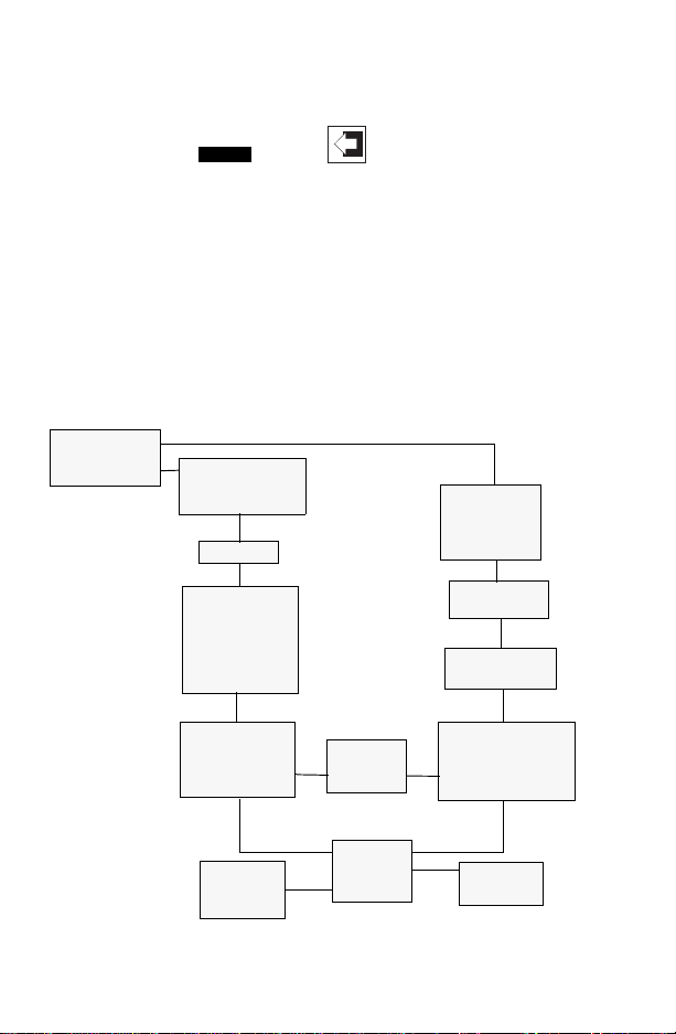
OFFLINE MENU
From the Main menu, press 1 to access the Offline menu. From the Offline
menu you can access the options: New Configuration and Saved
Configuration. Figure 1-11 shows a menu tree for the Offline f unctions.
A HART-compatible device does not have to be con nected to use th e offline
options, except when sending saved configuration data to a c onnected
device.
Offline Menu
1. New Config
2. Saved Config
Saved Configuration
1 Module
2 data pack
3PC
Name
Saved Configuration
1Edit
2 Copy to...
3 Send
4Print
5Delete
6 Rename
7Compare
Edit
1MarkAll
2 Unmark All
3 Edit individually
4SaveAs...
Edit
Configuration
Variables
Manufacturer
Listing
Model ID
Listing
Field Device Rev
Listing
From Blank Template
1MarkAll
2 Unmark All
3 Edit individually
4 Save As...
Save as...
Data Type
1 Standard
2 Partial
3Full
1 Location
2Name
3DataType
FIGURE 1-11. Offline Menu Tree.
1-13
Location
1 Module
2 data pack
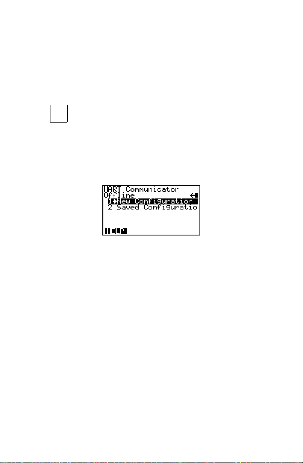
New Configuration (Offline)
Use this option to compile a custom set of device configuration data for
downloading to any HART-compatible device. You can download repeatedly
to multiple devices so that they store identical configuration data.
Offline configuration may not be available for all devices. Steps 2 and 3
below will help you verify if the desired manufacturer and device model are
programmed into the Communicator’s Memory Module.
1. Press on the Main menu to access the Offline menu. This menu
2. From the Offline menu, press 1. The Manufactu rer menu displays a list of
3. Select a manufacturer; the Model menu displays. The Model menu
4. Select a device model forconfiguration; the Field Device Revision (Fld dev
5. Select a device revision; the From Blank Template menu (Figure 1 -13)
STU
1
allows you to enter a new device configuration or edit a saved device
configuration.
To enter a new configuration, go to Step 2.
To edit a saved configuration, press 2 and go to Saved Configurati on
Menu (Offline) on page 1-17.
FIGURE 1-12. Offline Menu.
manufacturers with dev ice descriptions currently installed in your HART
Communicator.
contains a list of the currently installed device models provided by the
manufacturer.
rev) menu displays. The Fld dev rev menu contains the currently installed
software revisions for the field device and device descriptions (DD) for the
model you selected from the previous screen.
displays.
If you are unsure of the device revision, connect the HART Communicator
to the device and determine its device revision level. Youcan access this
information from the Online menu>Device Setup>Detailed Setup>Device
Information. See your device manual for more information.
1-14
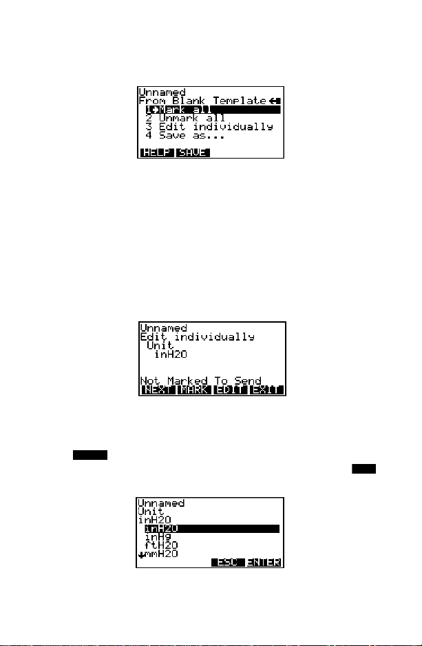
From Blank Template Menu
To access From Blank Template Menu, see steps 2 through 5 under New
Configuration (Offline) on page 1-14.
FIGURE 1-13. From Blank Template Menu.
The following options are available from the From Blank Template menu:
Mark all flags all configurable variables to be sent to a HART-compatible
device. Configuration variables are those that appear when you edit
variables in the c onfiguration using the Edit Individually option.
Unmark all removes the flags from all configurable variables in the
configuration. Unmarked configuration v ariables are not sent to a connected
HART-compatible device.
Edit individually (Figure 1-14) opens the Edit Individually menu containing
numerous configuration variables.
FIGURE 1-14. Edit Individually Menu.
For example, to change the engineering units from inH20 to ftH20, find the
configuration variable, press the Edit function key, highlight the new unit, and
press the function key. The Esc key returns you to the previous
screen as displayed in Figure 1-15. When you are done, press the
ENTER
EXIT
function key to return to the From Blank Template menu.
FIGURE 1-15. Unit Variable Menu.
1-15
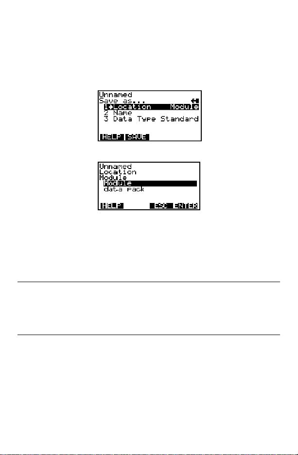
Save as... saves your new configuration to either the Mem ory Module or the
data pack 100. See Figure 1-16 and Figure 1-17. The Memory Module
holds up to 10 typical configurations, and contains the operating system
software, and device application software in nonvolatile memory. The data
pack stores up to 100 typical configurations in nonvolatile removable
memory.
FIGURE 1-16. Save As... Menu.
FIGURE 1-17. LocationMenu.
You can also use the Save As... menu to enter or edit the configuration name
and data type. Data Type Standard provides a Data Type menu with editable
options. Standard is the set of editable variables used when defining a new
device configuration. Partialis a set of marked variables. Full is the set of all
device variables.
NOTE: Configurations created offline in the HART Communicator will not
transfer to Asset Management Solutions (AMS) software; however, ‘Full’
configurations saved from a field device to a HART Communicator may be
uploaded to AMS. Configurations saved as ‘Full’ from an online device may
also be transferred directly to AMS.
After you have made all desired changes, save your new configuration to a
storage location and return to the Offline menu. Refer to Storage Location
Menu on page 1-28 for more i nform ation.
1-16
Saved Configuration Menu (Offline)
You can acces s configuration data already stored in your Communicator
through the offline Saved Configuration menu.
To access configuration data stored in your HART Communicator:
1. Press 1 on the Main menu to access the Offline menu.
2. Press 2 from t he Offline menu, and the Saved Configuration menu screen
displays (Figure 1-18).
FIGURE 1-18. Saved Configuration Menu (Offline).
3. Select either Module Contents or data pack Contents, as appropriate, to
open your stored configurations. Both storage locations list all saved
configurations by assigned Tag. See Xpandonpage1-18for m ore
configuration identification details.
The PC option is not operational with this release. Refer to Listen for PC
Menu on page 1-26 for details on interfacing with a PC.
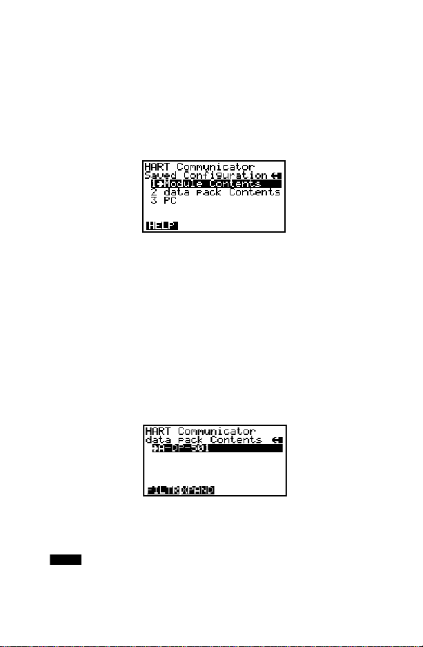
Data Pack Contents Menu
Figure 1-19 shows the data pack Contents menu, displaying a listing of
device configurations stored in the data pack. From the Saved Configuration
menu (Figure 1-18), press 2 to access the data pack Contents menu.
FIGURE 1-19. Data Pack ContentsMenu.
The following functions key s are available from the data pack Contents
menu:
The function key opens a menu t hat provides Sort and Filter options
FILTR
for customizing yourview of saved device configurations. Sortlets you group
and display device configurations according to your choice of Tag,
Descriptor,or Name. Tag Filter lets you view information according to what
1-17
you entered with Sort by picking characters from the device Tag, Descriptor,
or Name.
When setting up a filter, you can use the period (.) to replace a single
character of any value or the asterisk (*) to replace zero or more
alphanumeric characters of any value.
For example, if you enter A-*-.1, it should match all device tags starting with
A-, followed by any characters, followed by -, followed by any single
character, and ending with a 1. That means only devices starting with A-
and ending in 1, out of yourlist of saved device configurations, will display as
a group on the Communicator ’s screen.
XPAND
The function key allows you to view the Tag,Descriptor, and Name
for the current configuration. Select Com p ress to return to the previous
compressed screen with the current Tag or Descriptor or Name.
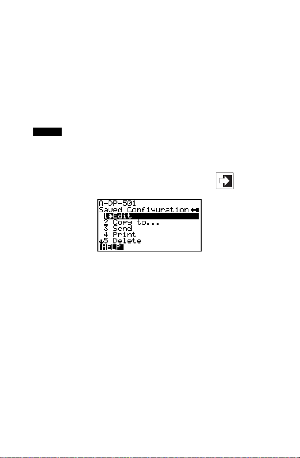
Saved Configuration Menu (data pack Contents)
From the data pack Contents menu (Figure 1-19), press to open the
Saved Configuration menu (Figure 1-20).
FIGURE 1-20. Saved Configuration Menu (data pack Contents).
The following functions are available from t he Saved configuration menu:
Edit displays the Edit menu. These edit functi ons are the same as described
under Edit individually on page 1-15. If you are editing online, remember
that only stored data can be edited. A Partial configuration canbe edited, but
you must convert it to a Standard configuration in order to save your edits.
Copy to... specifies the storage location where you want the copy to be
stored. You can also change the configuration name when using this option.
Send sends your saved configuration to a connected device.
Print requires AMS running in your computer. This option is intended for the
future. See Listen for PC Men u on page 1-26 for more information.
Delete removes a saved configuration from the m e mory storage location. A
confirmation message will appear. Press Yesor No to complete t he function.
1-18
Rename accesses the Configuration Name editing menu. After making
name changes, enter and save the data to return t o the previous storage
location menu.
Compare compares a selected device configuration from a stored location
with another device c onfiguration. The HART Communicator compares
device types, variables, marked lists, etc. Messages will appear indicating
whether the configurations compared are the same or different. Press OK to
return to the storage loca tion and your list of device configurations. Find and
make any necessary changes resulting from your comparisons.
In order to produce a “Same / Differ” result, the following conditions must be
met when comparing two configurations:
1. Device type (including manufacturer), device type number, device revision, and DD revision must match exactly.
2. Configurations can only be compared against other configurations
containing the same set of variables. The Communicator will notify you if
this condition is not met.
3. The format of data storage must match exactly. The Communicator will
notify you if this condition is not met.
User assigned configuration names are not considered, as they will differ.
ONLINE MENU
With a HART-compatible device connected, press on the Main menu
VWX
2
to access the Online menu (Figure 1-21).
5ø
12.øøø
FIGURE 1-21. Online Menu.
The Online menu displays the name of the device on the first line of the LCD.
You have complete functionality for a specific device only when that device
description is present in the HART Communicator. If the DD is not present in
the HART Communicato r, contact your nearest service representative.
The Online menu can be different depending on the connected device. See
your device-specific manual for O nlin e menu details. Or, see Section 3 for a
selection of device-specific menu trees.
1-19

When the DD for a specific device is not available, your HART
Communicator provides a generic interface. This generic interface enables
you to perform functions common to all HART-compatible devices.
Figure 1-22 shows the Generic Online menu tree.
The Online (Generic) menu is the first menu in the generic interface. This
menu displays critical, up-to-date device information such as the process
variable (PV), analog output(AO) , lower range value (LRV), and upper range
value (URV). Configuration parameters for the c onnected device are
accessed using the Device setup option.
The following functions are available from t he Generic Online m enu:
SAVE
The function key allows you to save a configuration from a
transmitted device. See Changing a Saved Configuration on page1-29 for
more details.
Device Setup accesses the Device Setup menu, containing configurable
device parameters common to all HART-compatible devices.
PV (Primary Variable) displays the dynamic PV and the related engineering
units. When the PV contains too many characters to display on the Online
menu, press 1 to access the PV menu and view the PV and related
engineering units.
AO (Analog Output) and related engineering units are displayed on the
Online menu. The AO is the signalon the 4–20 mA scale that corresponds to
the PV. When the analog output contains t oo many characters to display on
the Online menu, press 3 to access the PV AO menu and view the AO output
and related engineering units.
Current LRV (Lower Range Value)and related engineering units are
displayed on the Online menu. W hen the LRV contains too many characters
to display on t he Online menu, press 4 to access the PV LRV menu and view
the LRV and related engineering units.
Current URV (Upper Range Value) and the related engineering units are
displayed on the Online menu. When the URV contains too many charac ter s
to display on the Online menu, pr ess 5 to ac cess the PV URV menu and
view the URV and related engineering units.
1-20

1 Process
Variables
1 Present variable
2 Percent Range
3 Analog Output
Generic
Online Menu
1 Device Setup
2PV
3AO
4LRV
5URV
2 Diagnostics
and Service
3 Basic Setup
4 Detailed Setup
5 Review
1. Test Device
2. Loop Test
3. Calibration
4. D/A Trim
1. Tag
2. PV Snsr Unit
3. Range Values
4. Device Info.
5. Xfer Fnct n
6.PV Damp
1 Sensors
2Signal
Condition
3 Output
Condition
4 Device
Information
Self Test
1. Apply Values
2. Enter Values
1 Model
2Tag
3Date
4Descriptor
5 Message
6PVsnsrs/n
7 Final Asmbly #
8 Revision
1. Process Variables
2. PV Snsr Unit
3. Sensor Info
1PVDamp
2PVURV
3PVLRV
4XferFnctn
5 PV % Range
1. Analog Output
2. HART Output
1 Model
2Tag
3Date
4 Descriptor
5 Message
6PVSnsrS/N
7 Final Asmbly Num
8 Revision
1UnivRev.
2FldDevRev
3SoftwRev
1PVLSL
2PVUSL
3 PV Min Span
1A/O1
2A/OAlarmType
3 Loop Test
4D/ATrim
5ScaledD/ATrim
1 Poll Address
2 NumberofRequest
Preambles
1UnivRev.
2FldDevRev
3SoftwRev
FIGURE 1-22. Generic Online Menu Tree.
1-21
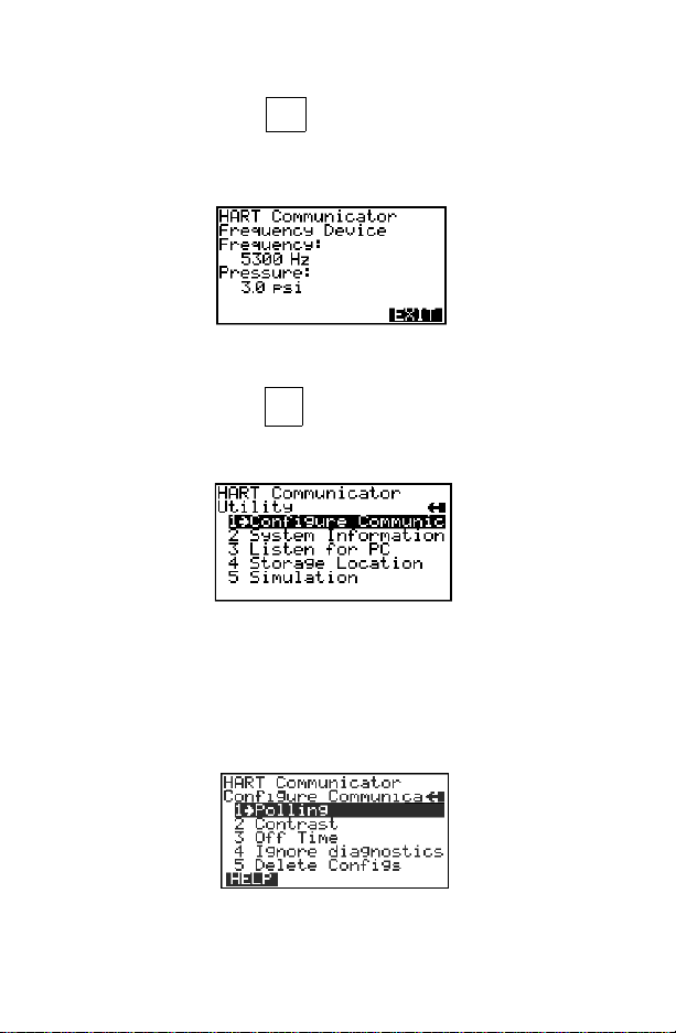
FREQUENCY DEVICE MENU
YZ /
From the Main menu, press to acces s the Frequency Device menu
(Figure 1-23). This menu display s the frequency output and corresponding
pressure output for the current-to-pressure devices.The output shown below
was taken from device Model 3311.
FIGURE 1-23. Frequency Device Menu.
3
UTILITY MENU
From the Main menu, press to access the Utility menu (Figure 1-24).
JKL
4
The Utility menu providesaccess to functions that affect only the operation of
the HART Communicator.
FIGURE 1-24. Utility Menu.
Configure Communic ator Menu
From the Utility menu, press 1 to access the Configure Communicator menu
(Figure 1-25). Use this menu to set the polling, adjust the LCD contrast, set
the Communicator off t ime, or set the number of ignore diagnostics
messages.
FIGURE 1-25. Configure Communicator Menu.
1-22

Polling Menu
Use the Polling options to configure your HART Communicator to
automatically search for all or specific connected devices. The HART
protocol allows you to communicate with multiple HART devices on a single
twisted pair of wires over leased telephone lines.
When several devices are connected in the same loop (multidropped), each
device must be assigned a unique address. To find the individual device
addresses, use the Digital Poll option to find each connect ed device in the
loop and list them by tag number.
Communication between the Communicator and multidropped transmittersis
digital, with the analog output fixed. In a multidrop installation, each
transmitter is identified by a unique polling address of 0 or 1–15 and
responds to the commands defined in the HART protocol.
Use the up and down arrow keys to highlight the desired polling option:
ENTER
Press (F4) to ent er the highlighted option and return to the Configure
Communicator menu. Or, press (F3) to return to the Configure
Communicator menu without changing the Polling.
From the Configure Communicator menu (Figure 1 -25), press to
ESC
STU
1
access the Polling menu (Figure 1-26).
FIGURE 1-26. Polling Menu.
The Polling options are:
Never Poll connects to a device at address 0, and if not found, will not poll
for devices at address 1–15.
Ask BeforePolling connects to a device at address 0, and if not found, asks
if you want to poll for devices at address 1– 15.
Always Poll connects to a device at address 0, and if not found, will
automatically poll for devices at address 1–15.
Digital Poll automatically polls for devices at address 1–15, regardless.
Poll Using Tag asks the user for a tag to use to connect to a device.
Refer to your device-specific manual for more information on changing a
device polling address.
1-23

Contrast Menu
The Contrast menu adjusts the contrast on the LCD. However, the first time
you reset and sav e the contrast, it is entered permanently.When you turn the
Communicator off, then on, the adjusted setting will reappear. If you need
help, call your service center for assistance.
Follow these steps to adjust the cont rast:
VWX
1. From the Configure Communicator menu, press to access the Con-
2
trast menu (Figure 1-27).
FIGURE 1-27. Contrast Menu.
2. Follow the on-screen instructions to adjust thedisplay contrast. Press
ESC
(F3) to return to the Configure Communicator menu without adjusting the
contrast. To save the changes to the contrast, press (F4) and the
ENTER
Configure Communicator menu displays.
Off Time Menu
Off Time is the amount oftime that elapses before your HARTCommunicator
turns off automatically when not in use. Use the following steps to set the
automatic turn off option:
YZ /
1. From the Configure Communicator menu, press to access the Off
3
Time menu (Figure 1-28).
FIGURE 1-28. Off Time Menu.
2. Use the numeric keys to select the automatic turnoff time or press
(F3) to return to the Configure Communicator menu without adjusting the
off time.
1-24
ESC

3. To save the off time change, press (F4) and the Configure
ENTER
Communicator menu displays.
Entering Zero (0) will disable this option. Themaximum time allowed is 255
minutes. However, be aware that no information will be received about the
improper operation of a field device when the Communicator is turned off.
Ignore Diagnostics Menu
The HART Communicator is designed to display diagnostic messages from a
connected device. The Ignore diagnostics opt ion allows you to specify the
number of ignored messages, extending t he time between displayed
messages. This count will default to a nominal count of 50 out of a range of
50–500 each time the Communicator i s turned on (Fig ure 1-29).
FIGURE 1-29. Ignore Diagnostics Menu.
Delete Configs Menu
The HART Communicator is capable of storing configurations in the Memory
Module or datapack. Youcan also add items to the Hotkey menu. The Delete
Configs menu allows you to delete in one step all configurations saved in the
module or data pack, as well as to delete all menu items added to the Hotkey
menu.
FIGURE 1-30. Delete Configurations Menu.
1-25

System Information Menu
VWX
From the Utility menu, press to access the System Information menu
(Figure 1-31).
FIGURE 1-31. System Information Menu.
Motherboard system information consists of the Serial Peripheral In terface
Time (SPI Time) and the firmware revision number.
Module system information consists of hardware and software data. For
example, you can find the hardware revision, RAM s ize, and Flash size; or,
the different software revisions and binary sizes.
data pack system information consists of the EEP ROM size and revision
number.
2
Listen for PC Menu
From the Utility menu, press toaccess the Listen for PC menu (Figure
YZ/
3
1-32).
FIGURE 1-32. Listen for PC Menu.
The Listen for PC menu allows you to set up your HA RT Communicator soit
can accept data transfer and requests from the PC. On the PC side, you
must be running Asset Management Solutions (AMS) software. If AMS is
installed, you can upload and download the device conf iguration information.
Accessing data stored in the HART Communicator from the connected PC is
a convenient way to view, compare, copy, and reconfigure field device
configurations.
1-26

Follow these steps to connect your HA RT Communicator to a PC:
1. Plug the PC Communication Adapter into the 9-pin Serial Port located on
the back of the Communicator. Refer to Appendix B for an illustration of
the PC Communication Adapter and the Communicator.
2. Plug the PC 25-pin Serial Port cable into the other end of the PC
Communication Adapter.
3. Connect the PC’s Serial Port cable to the back of the PC. Depending on
the PC, you must have either a 9-pin or 25-pin plug on the PC end of the
cable to connect to the PC.
4. Set the Communicator to List en for PC.
5. Move to the PC keyboard. All communication between the two systems is
initiated at the PC.
6. StarttheAMS application and select the HARTCommunicator icon to start
communication. Table 1-2 describes the main interface options selectable
by right-clicking the Communicator icon in AMS. Refer to the AMS
application online help system for details.
NOTE: AMS must also be configured appropriately to communicate with the
HART Communicator. See the AMS User’s Guide for details.
TABLE 1-2. Main Options for the PC AMS Interface.
Main Option Description
Open and close the connection to the HART
Communicator.
Optimize memory in the
HART Communicator.
View and change HART
Communicator properties.
Move data between the
HART Communicator,
connected devices, and
the AMS database.
Print device configuration.
Opens or closes the table of contents located in the
HART Communicator. This TOCis only a list of the configurations and includes partial configurations. It does
not contain the configuration parameters. The configurations are listed by name, tag, or description and are
grouped according to location: Memory Module or data
pack.
Compressesthememory in the HART Communicator’s
Memory Module and data pack. It helps avoid “out of
memory” conditions whenloading device configurations
into the Communicator.
Displays a property sheet where you can set the PC-toCommunicator operation options or check on
resources, versionnumber, and available memory.
Allows you to copy, cut, paste, and drag/drop icons as
well as move device configurations from the HART
Communicator to a connected device or to another
area in the database.
Allows you print out the device configuration parameters using the File menu Print command.
1-27

Storage Location Menu
From the Utility menu, press 4 to access the Storage Location menu
(Figure 1-33). The Storage Location menuallows you to access the Memory
Module or data pack memory permanent storage locations.
FIGURE 1-33. Storage Location Menu.
The PC option requires AMS software running in your computer. Refer to
Listen for PC Menu on page 1-26 for more information.
When either the Memory Module or data pack storage locations are opened,
you can use the Label submenu to view or edit the assigned name of the
label given to the selected storage location. Or, with the Space Usage
submenu, you can view the total memory and amount of free memory for the
storage location.
Simulation Menu
The HART Commu nicator provides a simulation mode that allows you to
simulate an online connection to a HART-compatibledevice without
connecting the device. The simulation mode is a training tool that enables
you to become familiar with different devices before configuring them in a
critical environment. A simulated configuration cannot be saved, however.
To simulate an online connection from the Main menu:
MNO
1. From the Utility menu, press to access the Simulation menu. See
Utility Menu on page 1-22. The Manufactur er menu displays a list of
manufacturers with device descriptions currently installed i n your Communicator.
2. Select a manufacturer. The Model menu displays, containing a list of
currently installed device models provided by the selected manufacturer.
3. Select the device you want to simulate. The Fld dev rev menu displays,
containing the current field device revisions for the selected model.
5
1-28

4. To access the main configuration menu, select the applicable device
revision. The Onlinemenu for the simulated device is displayed. Youcan
now use the HART Communicator as if it were c onnected to the selected
device, and perform any online task.
If you are unsure of the device revision, connect the HART Communicator
to the device and determine its device revision level. This i nf ormation is
most commonly accessed from Online menu>Device Setup>Detailed
Setup>Device Information. For more information, see your device-specific
manual.
SAVING A CONNECTED DEVICE CONFIGURATION
Selecting the option from any Online menu allows you to save a
configuration transmitted from a connected device to a permanent storage
location.
To save, change, and send a stored configuration:
1. Select .
2. Enter a storage location (Memory Module or data pack).
3. Enter a Name and configuration Data Type. Name defaults to the online
device Tag,and the Data Type defaults to Standard with all editable
variables marked.
NOTE: Saved configurations have to be “Full” for storing in your PC in AMS
software.
Warnings appear if there is not enough memory to store the transmitted
configuration or if t here is no list of configurable variables with Data Type
set to standard.
The key disappears until you change any configuration data.
4. To change the configuration data, go int o the Device Setup menu options
and change the required data. For example, if the Tag needs to be
changed, start with the Device Setup menu and go into the Basic Setup
menu options, open Tag, and change the data.
Press to load the changed data, then press to send your
changes to the connected device.
5. After each data configuration is sent, the function key appears. You
have the option to save the individual variable or continue to change all of
the variables and save them all at once.
SAVE
SAVE
ENTER
SAVE
SEND
SAVE
1-29

6. If you choose not to data but want to continue, the key will
reappear after each selection is entered.
7. Repeat the above process where necessary to modify each device
configuration.
When saving a new configuration or changing a saved configuration
offline, you will not encounter the send key.
SAVE
SEND
USING THE HOT KEY
The Hot Key menu isa user-definable menu that can hold up to 20 options of
your most frequently performed tasks.
Figure 1-34 shows a typical Hot Key menu with four added options. The first
option, Range values, is permanent and cannot be changed. It provides
quick access to review or modify the device range values.
To use the Hot Key,you must properly connect the HART Communicator to a
device. You can access the Hot K ey menu from any menu, or before
powering up the Communicator, by simply pressing the Hot Key.
To use the Hot Key menu:
1. Connect the HART Communicator to a HART-compatible device.
2. Press the Hot Key.
3. Initially,the Hot Key menu displays with only Rangevalues listed. Refer to
Customizing the Hot Key Menu on page 1-31 for details on how to add
options. The figure below shows some added options.
4. Select the desired option from the Hot Key menu.
FIGURE 1-34. Sample Hot Key Menu.
5. Follow the online instructions to perform the selected func tion.
NOTE: If your HART Communicator does not provide access to the Hot Key
menu for a particular device, that device does not support Hot Key
functionality.
1-30

Customizing the Hot Key Menu
You can customize the Hot Key menu to provide fast access to
Range values and your most frequently used tasks. Ran ge values is
a permanent option providing quick access to rerange. This optionc annot be
deleted from the H ot Key menu.
Adding Options to the Hot Key Menu
The Hot Key menu has space for up to 20 online options. F or example,if you
have to change device tags and damping often, you can add these functions
to the HotKey menu. The HART Communicator automatically saves them so
they can be quickly accessed by pressing the Hot Key.If you turn the unit off,
then later turn it back on using the Hot Key, your customized menu will
display.
With the Online menu or any of the submenu options open, use the following
steps to add c ustomized options to the Hot Key menu:
1. Using the up or down arrow key,move the menu bar to highlight the option
you want to add to the Hot Key menu.
2. Press any one of the three shift keys, release it, and then press the Hot
Key. This is shown in the following key sequence:
→
3. The Hotkey Configuration menu displays (Figure 1-35).
FIGURE 1-35. Hotkey Configuration Menu.
The Hotkey Configuration menu displays the new topic you want added to
the current list of Hot Key options. The figure above indicates that Tag is
being added to t he Hot Key menu in addition to the permanent R ange
values feature. Press (F3) to add the Tagoption to the Hot Key
menu. Press (F4) to exit the task and display the previous menu.
EXIT
ADD
1-31

4. Press (F1) to add the option to the Hot Key menu for all of the HART-
ALL
compatible devices supported in your Communicator; or, press (F4)
ONE
to add the option to the Hot Key menu for the specific device to which you
are currently connected. See Figure 1-36.
FIGURE 1-36. Adding a Hot Key Option.
5. If the message “Mark as read only variable on Hot Key menu?”
Figure 1-37 displays, press (F1) to m ark the variable for this option
as read-only, or press (F4) to mark the variable as read/write. For
YES
NO
example, marking the tag number of a device to beread-only allows you to
view, but not change, the tag number through the Hot Key menu.
FIGURE 1-37. Marking a Read-Only Hot Key Option.
When adding a variable such as tag number, you can choose to display
the current variable value as part of the menu option. If you choose to
display the value of the variable in the Hot K ey menu, the v alue appears
next to the option. Figure 1-38 shows the value of the tag displayed next
to the tag option on the Hot Key menu.
FIGURE 1-38. Hot Key Menu.
1-32

6. Press (F1) to display the variable associated with the option on the
7. Press (F4) on the Hot Key Configuration menu to complete the task.
YES
Hot Key menu, or press (F4) to not display it. See Figure 1-39.
EXIT
NO
FIGURE 1-39. Variable Display Option.
The options are now included on t he Hot Key menu.
Deleting Options from the Hot Key Menu
Use the following steps to delete an online option from the Hot Key menu:
1. Press any one of the three shift keys, release it, and then press the Hot
Key. This is shown in the following key sequence:
→
2. The Hotkey Configuration menu is displayed (Figure 1-40).
FIGURE 1-40. Deleting a Hot Key Option.
Move the menu bar to highlight t he option to be deleted and press
(F2). The menu bar will move to the next menu option. P ress (F2) to
delete the next highlighted option, as desired. The Range values
functionality cannot be deleted.
3. When you are through delet ing options, press (F4) to exit the Hotkey
EXIT
Configuration menu and return to the menu containing the option you just
deleted.
DEL
DEL
Note: For an easy method to quickly delete all menu items added to the Hot
Key menu, refer to Delete Configs Menu on page 1-25.
1-33

THE HART COMMUNICATOR AND THE YEAR 2000
The HART Communicator is Year 2000 Compliant if the operating system is
level 4.6 or greater. To determine the operating system level in your HART
Communicator, turn it on. The first screen displays the “Module Rev”, which
is the operating system level. If you need to update your operating system
software, contact your nearest product representative.
NOTE: When you power up the Communicator, the Firmware Rev number
appears first. A few seconds later, the Module Rev number displays one line
below the Firmware Rev.
Editing the Date
When you edit a date, you have three fields to edit: the firstfield is the month,
the second field is the day, and the third field is the year.
If you enter the year using two digits, the HART Communicator will assume
that the year is 1900 plus the value you enter.
If you enter four digits, the HART Communicator will use all four digits to
represent the year. By definition in the HART PROTOCOL, t he year must be
between 1900 and 2155.
When a date is displayed, the HART Communicator will display two digits in
the year if the year is between 1900 and 1999. If the year is 2000 or greater,
the HART Communicator will display all four digits.
FIGURE 1-41. Date Menu.
1-34

SERVICING THE HART COMMUNICATOR
As shown in Figure 1-42, t he modular construction of the HART
Communicator allows easy disassembly of the battery pack, the Memory
Module, and the data pack 100. This section discusses how to change
alkaline batteries, recharge the NiCad battery pack, upgrade the
Communicator software, and install and remove the data pack 100.
Replaceable
(AA)
or optional
rechargeable
(NiCad)
battery pack
data pack 100
FIGURE 1-42. HART Communicator Exploded View.
Memory Module
Calibrating the HART Communicator
It is not nec essary or possible to calibrate your HART Communicator. It has
no measurement circuitry and does not measure analog output from the field
device. The Comm unicator is strictly a communication interface that
communicates digitally with HART-compatible devices. It is not applicable to
NIST standards, and is not subject to calibration.
275-0275K01B
Using a Battery Pack
The HART Communicator is available with a battery pack that holds five AA
alkaline cells, or wit h a rechargeable nickel-cadmium power pack. The
alkaline cells last approximately 150 hours, and the NiCad cells last
approximately 60 hours with normal usage. When approximately one hour of
battery life remains, a low-battery icon appears in the upper right corner of
the display.
1-35

Changing Alkaline Batteries
!
WARNING
Explosions can result in death or serious injury. Do not remove or
replace battery pack in an explosive atmosphere.
Refer to Figure 1-43 and use the following steps to change alkaline
batteries:
FIGURE 1-43. Battery Pack Removal.
1. Completely loosen the three captive screws holding the Communicator
battery pack.
2. Grasp the battery pack and pull it away from the Communicator. Make
sure not to bend the pins connecting the battery pack to the
Communicator.
3. Remove and properly dispose of batteries.
4. Referring to the battery orientation diagram inside the battery pack, insert
five new AA alkaline batteries.
5. Carefully align the pins with the Communicator base and replace the
battery pack.
6. Tighten the three screws.
7. Turn on the C ommunicatorto verify operation and ensure the batteries are
installed properly.
1-36

Recharging the Battery Pack
!
WARNING
Explosions can result in death or serious injury. Do not recharge the NiCad
batterypack in an explosiveatmosphere.
NiCad battery packs are shipped from the factory discharged. Prior to the
first use, charge the battery pack while it is disconnected from the
Communicator. Subsequent charges may be performed while using or
storing the HART Communicator, without removing the battery pack.
NOTE: If the HART Communicator is stored for an extended period of time,
or the battery pack becomes completely discharged, remove the battery
pack from the Communicator and recharge it separately prior to using.
To recharge while us ing the Communicator, plug the recharger into an AC
outlet orpower source. Torecharge while storing the Communicator, plug the
recharger into an AC outlet or power source, m ake sure the HART
Communicator is off, and charge for 16 hours. Overcharging will not harm
the Communicator battery pack.
NOTE: For optimum performance, periodically discharge (use battery power
until the low battery icon appears) and then fully r echarge the battery pack.
Using a Memory Module
The HART Communicator i s supplied with a replaceable Memory M odule
(Figure 1-44). A 12 M B Memory Module is the recommended standard.
The Memory Module is programmed to communicate with specific HARTcompatible devices. Refer to Reviewing In stalled Devices o n page 1-12 to
find the specific HART-compatible devices that are programmed into your
Communicator’s Memory Module.
If you find that some specific devices are not listed in your Memory M odule,
contact your nearest service representative. Your Memory Module may be
reprogrammed or replaced to include support for the required HART devices.
1-37

Replacing the Memory Module
!
WARNING
Explosionscan resultin death or serious injury.Do not removeor replace
batterypack in an explosiveatmosphere.
Refer to Figure 1-43 and Figure 1-44, and use the following stepsto replace
the Memory Module:
FIGURE 1-44. Memory Module Replacement.
1. Completely loosen the three captive screws holding the Communicator
battery pack.
2. Grasp the battery pack and pull it straight up from the Communicat or. Do
not bend the battery pack’s connecting pins during the process.
3. Loosen the two captive screws holding the Memory Module.
4. Grasp the Memory Module and pull it away from the Communicator.
5. Align the new Memory Module with the Comm unicator, tighten the two
screws, and replace the battery pack.
1-38

Installing and Removing the Data Pack 100
Refer to Figure 1-43, Figure 1-44, and Figure 1-45.
Use the following steps to install or remove the data pack:
FIGURE 1-45. Data Pack 100 Installation and Removal.
To Install the data pack:
1. Remove the battery pack from the Communicator. Next, either remove the
Memory Module or leave it assembled to the Communic ator.
2.The data pack is keyed to prevent incorrect installation. When the
Communicator is facing down, insert t h e data pack with the part number
label facing down; the hinge of the handle will beon the left. Press firmly in
place with your fingers.
To remove the data pack:
1. Insert the flat edge of a small screwdriver under the outside edge of the
handle. Lift the han dle to disconnect the data pack from its connector.
2. Raise the handle and pull the data pack out of the Memory M odule.
1-39

1-40

SECTION 2 Common Tasks for Fisher-Rosemount HART Devices
INTRODUCTION
This section displays HART Communicator menus and describes tasks
common to Fisher-Rosemount HART products.
POWERING UP ONLINE
Powering up online provides direct access to the Online menu. This menu
provides critical data that is continuously updated. To be powered online, the
Communicator must be connected to a 4–20 mA loop.
To power up the Communicator and access a HART compatible device:
1. Be sure the Communicator is connected to a HART compatible device.
See HART Communicator Connections on page 1-2 for information
about proper connections.
2. Power the Communicator by pres sing the On/Off key.
NOTE: If a device is found, the HART Communicator displays the Online
menu. If no device is found, the Communicator displays the Main menu. If no
device is found, check the connections, verify t he presence of the 250 ohms
load resistance in series in the loop, and retry by selecting ‘Online.’ To poll
multiple devices in the loop, refer t o Polling Menu on page 1-23. For help
on communication problems, see Appendix D.
2-1

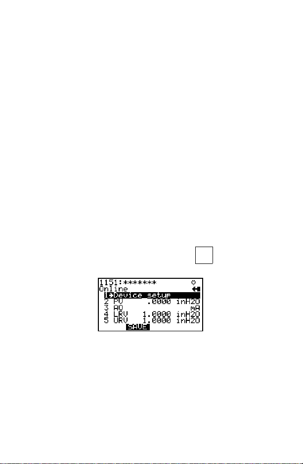
ONLINE MENU
The Online menu is the first menu to appear when the Communicator is
connected to a HART compatible device. This menu is structured to provide
important information about the connected device immediately on powering
up the Communicato r (Figure 2-1). This menu displays critical, up-to-date
device information including primary variable, analog output, lower range
value, and upper range value.
ø
5
12
ø
FIGURE 2-1. Online Menu.
Because of the important information provided in the Online menu, some
other menus provide instant access to it. When access is available, the
label appears above the F3 key. Press (F3) to return to the
HOME HOME
Online menu. For more information ab out the Home key,refer to Section 1.
Move through the menu using and and press to select an
option, or simply pr ess the corresponding numerical key. The Online menu
options are described as follows.
Device Setup
STU
Press to acc ess the Device Setup menu from the O nline menu.
The Device Setup menu accesses every configurable parameter of the
connected device. Refer to the Device Setup Menu on page 2-4 for more
information.
1
2-2

Primary Variable (PV)
VWX
Press to access Primary Variable.
2
The Online menu displays critical process information that is continuously
updated. If the PV and related engineering units are too long, they will not
appear on the Online menu. Select PV to view primary variable and the
related engineering units.
Analog Output (AO)
YZ /
Press to access Analog Output.
3
The analog output isthe signal on the 4–20 mA scale that corresponds to the
primary variable. When the AO contains too many characters to display on
the Online menu, select AO to view the analog output and related
engineering units.
Lower R ange Value (LRV)
JKL
Press to access Lower Range Value.
4
Select LRV to view the lower range value and related engineering units.
Upper Range Value (URV)
MNO
Press to access Upper Range Value.
Select URV to view the upper range value and relat ed engineering units.
5
2-3

DEVICE SETUP MENU
As shown in Figure 2-2, the Device Setup menu contains the following five
options:
STU
Press to access the Device Setup menu from the Online menu. The
1
options on this menu (Figure 2-2) are described in the f ollow ing paragraphs .
FIGURE 2-2. Device Setup Menu.
Process Variables
STU
Press to access the Process Variablesmenu.
1
This menu lists all process variables and their values. These process
variables are continuously updated.
Diag/Service
VWX
Press to access the Diag/Service menu.
This menu offers device and loop tests as well as calibration options. Figure
2-3 illustrates a typical menu.
2
FIGURE 2-3. Diagnostics and Service Menu.
Testdevice initiates a diagnostic routine at the device and can report an
electronics failure, as well as other failures that can affect performance.
2-4

Loop test can fix the transmitter out put at a specified analog value, and can
be used to test the integrity of the loop and the operation of indicators,
recorders, or similar devices in th e loop.
Calibration can include such operations as configuring output related
parameters, performing a sensor trim, o r performing an analog output trim.
Basic Setup
YZ /
Press to access the Basic Setup menu.
This menu provides quick access to a number of configurable parameters
including tag, unit, range values, and damping. Figure 2-4 illustrates a
typical Basic set u p menu.
The tag number identifies a specific device. Changing units affects the
engineering units that are displayed. Reranging changes the analog output
scaling. Changing damping affects the response time of the transm i tter to
smooth the output when there are rapid input variations.
The options available in the Basic Setup menu are the most fundamental
tasks that can be simply performed with a given device. These tasks are a
subset of the options available under the Detailed Setup menu.
3
FIGURE 2-4. Basic Setup Menu.
Detailed Setup
JKL
Press to access the Detailed setup menu.
This menu provides access to every editable device parameter and all
device functions. The Detailed Setup menu varies widely from one HART
compatible device to another. Functions in this menu can include tasks such
as characterization, configuration, and sensor and output trims.
4
2-5

Review
MNO
Press to access the Review menu.
5
This menu lists all of the parameters stored in the connected device,
including information about the measuring element, signal condition, and
output. It also includes stored information about the connected device such
as tag, materials of construction, and device software revision.
FAST KEY SEQUENCES
A fast key sequence is simply a sequence of numerical button presses,
corresponding to the menu options that lead you to a given task. For
example, Figure 2-5 displays the fast key sequence for trimming analog
output on a Model 1151 Pressure Transmitter.
1232
FIGURE 2-5. Sample Fast Key Sequence.
The first digit representsoption number one on the Online m enu. Once this
option is selected, the Device Setup menu appears. The second digit
represents option number two of the Devic e Setup menu, w hich is the
Diagnostics and Service menu. The Calibration menu is activated by
pressing the third digit, and the f ourt h digit accesses the trim analog output
option of the Calibration menu. T his example is illustrated for the Model 1151
Pressure Transmitter on page 2-7. For more detailed inform ation on f a st key
sequences, consult your product manual.
2-6

Trimming the analog output is a calibration of the output circuitry, by setting
the 4 and 20 mA points. Once the 4 and 20 mA points are set, all
intermediate values are automatically adjusted. See Menu Trees in Section
3 for a corresponding menu tree.
50
12
0
From the Device setup menu, select Diag/
Service.
From the Diag/Service menu, select
Calibration.
From the Calibration menu, select Trim
analog output.
From the Trim Analog Output menu, select
the desired option and follow the on-line
instructions.
From the Online menu, select Device setup.
2-7

2-8

SECTION 3 Menu Trees
INTRODUCTION
This section displays typical examples of menu trees for specific FisherRosemount products.
Menu trees show the primary commands and options available when using a
sequence of menu selections. Textdisplayed in all bold capital letters in the
menu trees indicates a progression to the next l evel. Due to space
limitations, all levels may not be shown. Also note that your specific device
could be different from the example shown. Consult your product manu al for
more detailed information.
The menu trees are identified by product and model number at the top of the
page and are arranged in numeric-alpha order.
3-1

Model 54pH/ORP Transmitter
1 PROCESS
VARIABLES
2DIAG/
SERVICE
3BASIC
SETUP
4DETAILED
SETUP
5 REVIEW
1 VIEW FLD DEV
VARS
2 VIEW PV-ANALOG 1
3 VIEW SV-ANALOG 2
4 View alarms
5 View status
1 TEST DEVICE
2 Fix analog output
3 CALIBRATION
4 Trim analog output
5 Hold mode
1Tag
2 PV RANGE VALUES
3 SV RANGE VALUES
4 ALARM SETPOINTS
5 DEVICE
INFORMATION
1 SENSORS
2 SIGNAL CONDITION
3 OUTPUT CONDTION
4 DEVICE INFORMATION
5 DIAGNOSTICS
6 LOCAL DISPLAY
1pH
2ORP
3Temp
4 Input
5 glass
6Ref
1SVis
2pH
3 pH & rnge
4AO
5 Convention
1 View status
2 View alarms
3 Master reset
1 CALIBRATE PV
2 ADJUST
TEMPERATURE
1pHLRV
2 pH URV
3pH
4 pH % rnge
5pHxferfun
1Spt
2Spt
3Spt
4Timer
5pH
6ORP
1 MAIN SENSOR
2 TEMPERATURE
1 ANALOG OUTPUT
2 Relay deflt
3 Fix analog output
4 Trim analog output
5HARTOUTPUT
1 SENSORS
2OUTPUTS
3 ALARM RELAYS
4 DIAGNOSTICS
5 DEVICE
INFORMATION
6 LOCAL DISPLAY
3-2
1PVis
2pH
3pH&rnge
4AO
5 Convention
1pHLRV
2 pH URV
3pH
4 pH % rnge
5pHxferfun
1Tag
2 Descriptor
3 Message
4 Snsr text
5Date
1 PV RANGE VALUES
2 SV RANGE VALUES
3ALARM1
4ALARM2
5ALARM3
6Type
1 Diagnostics
2GFH
3GFL
4RFH
5 0 limit
6Calwarn
1 StandardizepH
2 StandardizeORP
3pH
4ORP
5 0 offset
6 0 offset
7 Slope
8 Buffer calibration
9 Buffer calibration
1 Begin procedure
2Temp
3Tempcomp
4 Man. temp
1PVis
2 Imped comp
3 Convention
4 Autocal
5 SST
6 SSS
7Operiso
8Snsriso
9TC
1Tempsnsr
2Tempcomp
3 Man. temp

Model 333 HART® Tri-Loop Converter
1 DEVICE SETUP
1DIAG/
SERVICE
2BASIC
SETUP
3DETAILED
SETUP
1 TEST DEVICE
2 Loop test
3 CALIBRATION
4 D/A trim
1Tag
2 CONFIGURE
CHANNELS
3 DEVICE
INFORMATION
1OUTPUT
CONDITION
1STATUS
2 Reset
1 CONFIGURE
CHANNELS
2 Recall fact trim
1 CONFIGURE CH1
2 CONFIGURE CH2
3 CONFIGURE CH3
1Model
2Devid
3Tag
4Date
5 Descriptor
6 Message
7 Final asmbly
num
8 REVISION #'S
1ANALOG
OUTPUT
2 HART
OUTPUT
1 Status group 1
2 Status group 2
1 CONFIGURE CH1
2 CONFIGURE CH2
3 CONFIGURE CH3
1 CH1 Burst Variable
2 CH1 Units
3 CH1 Lower Range
4 CH1 Upper Range
5 CH1 Enabled
1 CH2 Burst Variable
2 CH2 Units
3 CH2 Lower Range
4 CH2 Upper Range
5 CH2 Enabled
1 CH3 Burst Variable
2 CH3 Units
3 CH3 Lower Range
4 CH3 Upper Range
5 CH3 Enabled
1 Universal rev
2Flddevrev
3 Software rev
1 Loop test
2D/Atrim
3 Scaled D/A trim
1Polladdr
2 Num req preams
3 Num resp preams
4 REVIEW
2 DEVICE
INFORMATION
3-3
1Model
2Devid
3Tag
4Date
5 Descriptor
6 Message
7 Final asmbly
num
8 REVISION #'S
1 Universal rev
2Flddev rev
3 Software rev

1 DEVICE SETUP
2PV
3PVAO
4PVLRV
5PVURV
Model 644 Temperature Transmitter
1Snsr1
2 Snsr 1 % Rnge
1 PROCESS
VARIABLES
2DIAGNOSTIC
AND
SERVICE
3 BASIC SETUP
4DETAILED
SETUP
5REVIEW
3 Snsr 1 A/O Output
4 TermTemp
5 VARIABLE MAPPING
1 TEST DEVICE
2LOOPTEST
3 CALIBRATION
4 Smart Calibration
1Tag
2PVUnit
3 RANGE VALUES
4 CONNECTIONS
5PVDamp
6 Sensor 1 Snsr s/n
1SENSORS
2 SIGNAL
CONDITION
3OUTPUT
CONDITION
4DEVICEINFO
1PV
2SV
1 Status
2SelfTest
3 Master Test
14ma
220ma
3 Other
4End
1 APPLLY VALUES
2 RANGE VALUES
3 SNRS TRIM
4D/ATrim
5 Scaled D/A Trim
1 Differential Temp
2 TerminalTemp
3 Sensor 1
4 Sensor 2
1 Select Sensor
1 PROCESS
SENSOR
2 TERM TEMP
SENSOR
3 A/D CONVR
INFO
1LRV
2 URV
3 Snsr % Rnge
4 Snsr Damp
5XfrFunt
1 ANALOG
OUTPUT
2 HART
OUTPUT
1SnsrType
2 Snsr Connect
3Snsr1s/n
4 50/60 Hz Filter
5 Final Assembly
6Tag
7 Descriptor
8 message
9 Date,
Model...etc.
1#ofWires
1 TermTemperature
2Unit
3 Damping
4 Term Temp Limits
1 50/60 Hz filter
1 A/O Output
2A/OAlrmType
3LOOPTEST
4D/ATrim
5ScaledD/A
1 Unit Rev
2FldDevRev
3 Software rev
14ma
220ma
3Exit
1PVLRV
2 PV URV
3PVEngUnits
4 Lower Snsr Lmts
5 Upper Snsr Lmt
1OHM/MVTrim
2SENORREF
3 RE-ENABLE
TRIM
1FactoryTrim
2 Sensor 1 Trim
3 Sensor Ref
1PVUnits
1PVSnsr1
2PVUnit
3 SENSORSETUP
4 SENSOR INFO
5 SENSOR TRIM
Trim
1PollAddress
2 # Reqst Preams
3 Burst Mode
4 Burst Options
14ma
220ma
3Other
4End
3-4

Model 1151 Pressure Transmitter
1 DEVICE
SETUP
2PV
3AO
4LRV
5 URV
1 PROCESS
VARIABLES
2DIAGNOSTICS
AND SERVICE
3 BASIC SETUP
4DETAILED
SETUP
5 REVIEW
1Pressure
2 Percent Range
3 Analog Output
1 TEST DEVICE
2LoopTest
3 CALIBRATION
1Tag
2Unit
3 RANGE
VALUES
4 DEVICE INFO
5 Transfer Function
6Damp
1 SENSORS
2 SIGNAL
CONDITION
3OUTPUT
CONDITION
4 DEVICE
INFORMATION
1 Self test
2 Status
1 RERANGE
2 TRIM ANALOG
OUTPUT
3SENSORTRIM
1 Keypad Input
2 Apply Values
1Date
2Descriptor
3 Message
4 Write Protect
5 Meter Type
1 PROCESS
VARIABLES
2SENSOR
SERVICE
3Unit
1 PROCESS
VARIABLES
2 RANGE
VALUES
3Unit
4 TransferFunction
5Damp
1 PROCESS
VARIABLES
2 ANALOG
OUTPUT
3 Analog Output
Alarm
4 HART OUTPUT
1FieldDeviceInfo
2SensorInfo
3 Meter Type
4SelfTest
3-5
1 Keypad Input
2 Apply Values
1 Digital-to-Analog Trim
2 Scaled D/A Trim
1ZeroTrim
2 Lower Sensor Trim
3 Upper Sensor Trim
4 Sensor Trim P oints
1 Pressure
2 Percent Range
1 SENSOR TRIM
2 Characterize
1 Pressure
2 Percent Range
1 Keypad Input
2 Apply Values
1Pressure
2 Percent Range
3 Analog Output
1 Loop Test
2 Digital-to-Analog Trim
3 Scaled D/A Trim
1PollAddress
2 Number of Request Preambles
3 Burst Mode
4BurstOption
1ZeroTrim
2LwrSnsrTrim
3UprSnsrTrim
4 Trim Points

Model 2081C C onductivity Transmitter
1 PROCESS
VARIABLE
2DIAGNOS
AND
SERVICE
3 BASIC
SETUP
4DETAILED
SETUP
5REVIEW
1 VIEW FIELD
DEVICE
VARIABLES
2VIEWPV-
ANAOLOG 1
3ViewStatus
1ViewStatus
2 Loop Test
3 CALIBRATION
4 Trim Analog Output
1Tag
2 PV RANGE VALUES
3 DEVICE INFORMATION
1SENSOR
2 SIGNAL
CONDITION
3OUTPUT
CONDITION
4 DEVICE INFO
1SENSORS
2OUTPUTS
3DEVICEINFORM
1C
2 Temperature
3AC
1PVis
2PV
3 PV % Range
4PVA/O
1 STANDARDIZE COND
2 INITIAL SETUP
3 ADJUST TEMPERATURE
1PVLRV
2PVURV
3PVDamp
4PVpH
5 PV % Range
6XferFun
1 TempComp
2Man.Comp
1pHLRV
2pHURV
3pHDamp
4pH
5 pH % Range
6pHxferfun
1 ANALOG OUTPUT
2 HART OUTPUT
1Tag
2 Descriptor
3Message
4Date
5 Snsr Text
6BurstMode
7 Burst Option
8 Num Req Preams
9WriteProtect
10 Distributor
11 Manufacturer
12 Model
13 etc.
1 Begin Procedure
2C
3 Cell Const
4 Cell Factor
1 Cell Const.
2 Sensor Zero
3 TEMP SLOPE CAL
1 Begin Procedure
2Temp
3 TempComp
4Man.Temp
1Tag
2 Descriptor
3 Message
4 Snsr Text
5Date
1PVA/O
2 Loop Test
3 Trim Analog Output
1 Poll Address
2 TempUnit
3 Burst Option
4 Burst Mode
3-6

Model 2081pH Transmitter
1 PROCESS
VARIABLE
2DIAGNOS
AND
SERVICE
3 BASIC
SETUP
4DETAILED
SETUP
5REVIEW
1VIEWFIELD
DEVICE
VARIABLES
2VIEWPV-
ANAOLOG 1
3ViewStatus
1 TEST/STATUS
2 Loop Test
3 CALIBRATION
4 Trim Analog Output
1Tag
2 PV RANGE VALUES
3 DEVICE INFORMATION
1 SENSOR
2 SIGNAL
CONDITION
3OUTPUT
CONDITION
4DEVICEINFO
1pH
2 Temperature
3 Input
1PVis
2PVpH
3 PV % Range
4PVA/O
1ViewStatus
2 Master Reset
1 BUFFER CALIBRATION
2 STANDARDIZE ph
3 ADJUST TEMPERATURE
1PVLRV
2PVURV
3PVDamp
4PVpH
5 PV % Range
6XferFun
1 TempComp
2 Man. Comp
1pHLRV
2pHURV
3pHDamp
4pH
5 pH % Range
6pHxferfun
1 ANALOG OUTPUT
2 HART OUTPUT
1Tag
2 Descriptor
3 Message
4Date
5 Snsr Text
6 Burst Mode
7 Burst Option
8 Num Req Preams
9 Write Protect
10 Distributor
11 Manufacturer
12 Model
13 etc.
1 Begin Procedure
2 Slope
3pH
1 Begin Procedure
2pH
1 Begin Procedure
2Temp
3TempComp
4 Man. Temp
1Tag
2Descriptor
3 Message
4SnsrText
5Date
1PVA/O
2 Loop Test
3 Trim Analog Output
1 Poll Address
2TempUnit
3BurstOption
4 Burst Mode
3-7

1 DEVICE SETUP
S
2PV
3AO
4LRV
5URV
Model 2088 Pressure Transmitter
1Pres
1 PROCESS
VARIABLES
2 DIAG/SERVICE
3 BASIC SETUP
4DETAILED
SETUP
5REVIEW
2%rnge
3AO
1 TEST DEVICE
2 Loop test
3CALIBRATION
1Tag
2Unit
3 RANGE VALUES
4 DEVICE
INFORMATION
5Damping
6METER
OPTIONS
1 SENSORS
2 SIGNAL
CONDTION
3OUTPUT
CONDITION
4 DEVICE
INFORMATION
1Selftest
2STATUS
1 RE-RANGE
2ANALOG
OUTPUTTRIM
3 SENSOR TRIM
1 Keypad input
2 Apply values
1Date
2 Descriptor
3 Message
4 Write protect
1 Meter type
2CMSETUP
1 PRESSURE
SENSOR
1 PROCESS
VARIABLES
2RANGE
VALUES
3Unit
4Damping
1 PROCESS
VARIABLES
2ANALOG
OUTPUT
3HARTOUTPUT
4METER
OPTIONS
1 FIELD DEVICE
INFO
2 SENSOR
INFORMATION
3Selftest
4DIAPHRAM
EAL INFO
1 Keypad input
2 Apply values
1 D/A trim
2 Scaled D/A trim
1Zerotrim
2 Lower sensor trim
3 Upper sensor trim
4 Snsr trim cal typ
5 SENSOR TRIM
POINTS
1 Sel dec pt pos
2CMUpperValue
3 CM Lower value
4CMUnits
1 PROCESS
VARIABLES
2 SENSOR TRIM
3Unit
1Pres
2%rnge
3AO
1 Loop test
2 D/A trim
3 Scaled D/Atrim
4AOAlrmtyp
1 Poll addr
2Numreqpreams
3 Burst mode
4 Burst option
1Metertype
2CMSETUP
3CMV
1 Meas typ
2Isoltrmatl
3 Fill fluid
4 Process Connector
5 Process Conn Matl
3-8

Model 2090 Pressure Transmitter
1 DEVICE SETUP
2PV
3AO
4LRV
5 URV
1 PROCESS
VARIABLES
2 DIAG/SERVICE
3 BASIC SETUP
4DETAILED
SETUP
5 REVIEW
1Pres
2 % rnge
3AO
1 TEST DEVICE
2 Loop test
3 CALIBRATION
1Tag
2Unit
3 RANGE VALUES
4 DEVICE
INFORMATION
5 Damping
6 METER
OPTIONS
1 SENSORS
2SIGNAL
CONDITION
3OUTPUT
CONDITION
4 DEVICE
INFORMATION
3-9
1 Self test
2 STATUS
1 RE-RANGE
2ANALOG
OUTPUT TRIM
3 SENSOR TRIM
1 Keypad input
2 Apply values
1Date
2 Descriptor
3 Message
4 Write protect
1 Meter type
3 CM SETUP
1 PRESSURE
SENSOR
1 PROCESS
VARIABLES
2RANGE
VALUES
3Unit
4 Damping
1 PROCESS
VARIABLES
2ANALOG
OUTPUT
3HARTOUTPUT
4 METER
OPTIONS
1 FIELD DEVICE INFO
2 SENSOR INFORMATION
3 Self test
4 DIAPHRAM SEAL INFO
1 Keypad input
2 Apply values
1 D/A trim
2 Scaled D/A trim
1Zerotrim
2 Lower sensor trim
3 Upper sensor trim
4 Snsr trim cal typ
5 SENSOR TRIM
POINTS
1 Sel dec pt pos
2 CM Upper Value
3 CM Lower Value
4CMUnits
1 PROCESS
VARIABLES
2SENSORTRIM
3Unit
1Pres
2 % rnge
1 Keypad input
2 Apply values
1Pres
2 % rnge
3AO
1 Loop test
2 D/A trim
3 Scaled D/A trim
4AOAlrmtyp
1 Meter type
2 CM SETUP
3CMV

Model 3001S Hydrostatic Transmitter
1 DEVICE SETUP
2PV
3PVAO
4PVLRV
5PVURV
1 PROCESS
VARIABLES
2 DIAGNOSTICS
AND SERVICE
3 BASIC SETUP
4DETAILED
SETUP
5 REVIEW
1Pres
2%rnge
3A/O
4 Snsr temp
1 TEST DEVICE
2 Loop Test
3 CALIBRATION
1Tag
2PVUnit
3 Range Values
4 DEVICE INFO
5 Trans Funct
6 Damping
1 SENSORS
2 SIGNAL
CONDITION
3OUTPUT
CONDITION
4DEVICEINFO
1 Self Test
2Status
1 RE-RANGE
2 TRIM ANALOG
OUTPUT
3 SENSOR TRIM
1Date
2Descriptor
3 Message
4WriteProtect
5 Meter Type
1 PRESSURE
SENSOR
2TEMP
SENSOR
1PV
2RangeValues
3Unit
4 Transfer Funtion
5 Damping
1PV
2 ANALOG
OPUTPUT
3 A/O Alrm
Trim
4 HART
OUTPUT
1 Field Device Information
2 Sensor Information
3 Meter Type
4SelfTest
1PV
2 SENSOR
SERV
3 UNIT
1 Sensor Temp
2 Snsr Temp Unt
1Pres
2 % rnge
3 Snsr temp
1 Loop Test
2D/ATrim
3ScaledD/ATrim
1 Poll Address
2 Num Req Preams
3 Burst Mode
4 Burst Option
1 Keypad Input
2 Apply Values
1D/ATrim
2ScaledD/ATrim
1ZeroTrim
2 Lower Snsr Trim
3 Upper Snsr Trim
4 Sensor Trim Points
1Pres
2%rnge
3 Snsr temp
1 Sensor Trim
1Pres
2%rnge
3 Snsr temp
1 Keypad Input
2 Apply Values
3-10

Model 3044C Temperature Transmitter
1 DEVICE
SETUP
2PV
3PVAO
4PVLRV
5 PV URV
1 PROCESS
VARIABLES
2 DIAGNOSTICS
AND SERVICE
3 BASIC SETUP
4DETAILED
SETUP
5 REVIEW
1 Sensor 1
2 Sensor 1 Percent Range
3 Sensor 1 Analog Output
4 Electronics Temperature
5 Variable Mapping
1 TEST DEVICE
2 Loop Test
3 CALIBRATION
1Tag
2PVUnit
3 Range Values
4 Connections
5PVDamp
6 Sensor 1 Sensor s/n
1 SENSORS
2 SIGNAL
CONDITION
3OUTPUT
CONDITION
4DEVICE
INFORMATION
1 Status
2 Self Test
3MasterTest
1 Apply Values
2 Range Values
3 SENSOR TRIM
4 Digital-to-Analog Trim
5 Scaled D/A Trim
1 PROCESS
2 ELECT TEMP
1 Sensor 1 LRV
2 Sensor 1 URV
3 Sensor 1 Percent Range
4 Sensor 1 Damp
5 Transfer Function
1 ANALOG
2 HART
3 Meter Type
SENSOR
SENSOR
OUTPUT
OUTPUT
1 Sensor Input Trim
2 Sensor Trim-Factory
1 Sensor 1
2Snsr1Unit
3SENSOR
SETUP
4 Sensor Info
5SENSOR
TRIM
1 Electronics Temperature
2Unit
3 Electronics Temperature Limits
1 Analog Output
2A/OAlarmType
3 Loop Test
4 Digital-to-Analog Trim
5 Scaled D/A Trim
1 Poll Address
2 Number of Request Preambles
3 Burst Mode
4 Burst Option
1 Connections
2 Snsr 1 snsr s/n
1 Snsr Input Trim
2SnsrTrim-Factory
3-11

1DEVICE
SETUP
2PV
3AO
4LRV
5 URV
Model 3051 Pressure Transmitter
1Pres
1 PROCESS
VARIABLES
2DIAG/
SERVICE
3BASIC
SETUP
4DETAILED
SETUP
5 REVIEW
2 %rnge
3AO
4Snsrtemp
1 TEST DEVICE
2 Loop Test
3 CALIBRATION
1Tag
2Unit
3RANGE
VALUES
4 DEVICE
INFORMATION
5Transfer
function
6 Damping
7METER
OPTIONS
1 SENSORS
2SIGNAL
CONDITION
3OUTPUT
CONDITION
4 DEVICE
INFORMATION
1 Self test
2 STATUS
1 RE-RANGE
2ANALOG
OUTPUT TRIM
3 SENSOR TRIM
4 Recall fact trim
1 Keypadinput
2 Apply values
1Date
2 Descriptor
3 Message
4 Writeprotect
1 Meter type
2 CM SETUP
1 PRESSURE
SENSOR
2 TEMPERATURE
SENSOR
1 PROCESS
VARIABLES
2 RANGE VALUES
3Unit
4 Transferfunction
5 Damping
6 Snsr temp unit
7ALARM/SAT
LEVELS
1 PROCESS
VARIABLES
2ANALOG
OUTPUT
3HARTOUTPUT
4 METER OPTIONS
1 Keypadinput
2 Apply values
1 D/A trim
2 Scaled D/A trim
1Zerotrim
2 Lower sensor trim
3 Upper sensor trim
4 Snsr trim cal typ
5 SENSOR TRIM
POINTS
1 Sel dec pt pos
2 CM Upper Value
3 CM Lower Value
4CMUnits
5CMxffnct
1 PROCESS VARIABLES
2 SENSOR SERVICE
3Unit
1Snsrtemp
2 Snsr temp unit
1 Press
2 %rnge
3Snsrtemp
1 Keypadinput
2 Apply values
1 High Alarm
2 Low Alarm
3HighSat
4 Low Sat
5AOAlrmtyp
6 Alarm/Sat Type
1 FIELD DEVICE INFO
2 SENSOR
INFORMATION
3 Self test
4 DIAPHRAMSEAL
INFO
3-12

Model 3051C Pressure Transmitter (Original)
1 DEVICE
SETUP
2PV
3AO
4LRV
5URV
1 PROCESS
VAR
2 DIAGNOS
AND
SERVICE
3 BASIC
SETUP
4DETAILED
SETUP
5 REVIEW
1 Pressure
2 Percent Range
3 Analog Output
4 Sensor Temperature
1 TEST DEVICE
2 Loop Test
3 CALIBRATION
1Tag
2Unit
3 RANGE
VALUES
4DEVICEINFO
5 Transfer
Function
6Damp
1 SENSORS
2 SIGNAL
CONDITION
3OUTPUT
CONDITION
4DEVICEINFO
1 RERANGE
2TRIM
ANALOG
OUTPUT
3 SENSOR
TRIM
1 Keypad Input
2 Apply Values
1Date
2 Descriptor
3Message
4WriteProtect
5 Meter Type
1 PRESSURE
SNSR
2 TEMP. SENSOR
6 PROCESS
VARIABLES
7 RANGE VALUES
8Unit
9 Transfer Function
10 Damp
1 PROCESS
VARIABLES
2 ANALOG
OUTPUT
3 Analog Output
Alarm
4 HART OUTPUT
1 FIELD DEVICE
INFO
2SENSORINFO
3 METER TYPE
4 Self Test
3-13
1 Self test
2 Status
1Keypad
Input
2 Apply Values
1 Digital-to-
Analog Trim
2ScaledD/ATrim
1ZeroTrim
2 Lower S ensorTrim
3 Upper SensorTrim
4 Sensor Trim Points
1 PROCESS
VARIABLES
2 SENSOR
SERVICE
3Unit
1 Snsr Temp
2 Snsr Temp Units
1 Pressure
2 Percent Range
3 Snsr Temp
1 Keypad Input
2 Apply Values
1Pressure
2 Percent Range
3 Analog Output
4 Snsr Temp
1 Loop Test
2 Digital-to-Analog
Trim
3ScaledD/ATrim
1 Poll Address
2 Nmbr of Request Pream
3 Burst Mode
4 Burst Option
1 % Range
2Alt.%
Range
1 Pressure
2 % Range
3Snsrtemp
1SNSR
TRIM
1 Meas. Type
2Isolator
Mtrl.
3FillType
4 Flange
Type
5 Flange Mat.
6O-RingMat.
7DVMat.
8#ofRmt
Seals
9RSType
10 RS Mat.
11 RS Fill
1Zero
Trim
2LwrSnsr
Trim
3UprSnsr
Trim
4Snsr
Trim Pts.
1Tag
2Date
3 Descriptor
4Message
5 Model
6Write
Protect
7 Local Keys
8 Revisions
#s

Model 3081C C onductivity Transmitter
1 PROCESS
VARIABLES
2DIAG/
SERVICE
3BASIC
SETUP
4DETAILED
SETUP
5 REVIEW
1 VIEW FLD DEV
VARS
2 VIEW PV-
ANALOG 1
3 Vew status
1 TEST DEVICE
2 Loop test
3 CALIBRATION
4 D/A trim
5 Hold mode
1Tag
2PVRANGE
VALUES
3 DEVICE
INFORMATION
1 SENSORS
2SIGNAL
CONDITION
3OUTPUT
CONDITION
4 DEVICE
INFORMATION
5LOCAL
DISPLAY
1C
2T
3L
4R
5NaOH
6 HCl
7H2SO4low
8H2SO4hi
9Temp
10 A
1 View status
2 Master reset
3 View history
1 STANDARDIZE
PV
2 INITIAL SETUP
3 ADJUST
TEMPERATURE
1Tag
2 Descriptor
3 Message
4Snsrtext
5Date
1MAINSENSOR
2 TEMPERATURE
1 ANALOG OUTPUT
2HARTOUTPUT
1 SENSORS
2OUTPUTS
3 DEVICE
INFORMATION
4 LOCAL DISPLAY
3-14
1PVis
2C
3T
4L
5R
6NaOH
7 HCl
8H2SO4low
9H2SO4hi
10 Cond %rnge
11 AO
1 Begin procedure
2Temp
3Tempcomp
4 Man. temp
1 Cond LRV
2 Cond URV
3C
4T
5L
6R
7NaOH
8 HCl
9H2SO4low
10 H2SO4 hi
11 Cond %rnge
12 Cond xfer fun
1Tempcomp
2 Man. temp
3Tempsnsr
1Begin
procedure
2C
3T
4L
5R
6NaOH
7 HCl
8H2SO4low
9H2SO4hi
10 Cell const
11 Cal const
12 Cell factor
1 Sensor zero
2C
3T
4L
5R
6NaOH
7 HCl
8H2SO4low
9H2SO4hi
10 Cell const
11 Cell factor
12 Cal const
13 Slope
14 Temp slope cal
1PVis
2 Meas. range
3 Slope
4 Cell const
5 Cal const
6 Cell factor
1 Cond LRV
2 Cond URV
3C
4T
5L
6R
7NaOH
8 HCl
9H2SO4low
10 H2SO4 hi
11 Cond % rnge
12 Cond xfer fun

Model 3081FG Oxygen Analyzer
1 DEVICE
SETUP
2PV
3PVAO
3LRV
4 URV
5 Device SN
6 Alarm value
1 PROCESS
VARIABLES
2 DIAG/SERVICE
3 BASIC SETUP
4DETAILED
SETUP
5 REVIEW
1VIEWFLDDEV
VARS
2VIEWOUTPUT
VARS
1 Device Status
2 Loop test
3O2CALCHECK
4 D/A trim
5MAXCELLTEMP
1Tag
2 SELECT O2
RANGE
3 Alarmvalue
4 DEVICE
INFORMATION
5 S/W VERSION INFO
1 SENSORS
2SIGNAL
CONDITION
3OUTPUT
CONDITION
4 Filter
1 DEVICE
INFORMATION
2OUTPUTS
CONFIG
1 O2 value
2 Cell Temp
3CellmV
1 VIEW PV-AOUT
2VIEWSV
3VIEWTV
4VIEW4V
1 Start Calcheck
2 OPtrakTG?
3 HighTG
4 LowTG
5 Slope
6 Constant
1 URV
1Ver
2Bld
3BldDate
1O2
2 CELL TEMP
302CELLIMP
1 URL
2LRV
3 %rnge
1ANALOG
OUTPUT
2HART
OUTPUT
1PVis
2 O2 value
3 %rnge
4 O2 output
1SVis
2SV
1TVis
2TV
14Vis
24V
1MaxTemp
2 Reset Max Temp
1Devid
2 Descriptor
3 Message
4Date
5 Final asmbly num
6Snsrs/n
1 O2 value
2 Snsr unit
3USL
4LSL
5 Min span
1 Cell Temp
2 Snsr unit
3USL
4LSL
5 Min span
1CellmV
2 Snsr unit
3USL
4LSL
5 Min span
1 O2 output
2AOAlrmtyp
3 Loop test
3 D/A trim
1 Poll addr
2 Num req preams
3-15

Model 3081pH Transmitter
1 PROCESS
VARIABLE
2DIAGNOS
AND
SERVICE
3 BASIC
SETUP
4DETAILED
SETUP
5 REVIEW
1 VIEW FIELD
DEVICE
VARIABLES
2VIEWPV-
ANAOLOG 1
3ViewStatus
1 TEST DEVICE
2 Loop Test
3 CALIBRATION
4 Trim Analog Output
5 Hold Mode
1Tag
2 PV RANGE VALUES
3 DEVICE INFORMATION
1SENSOR
2 SIGNAL
CONDITION
3OUTPUT
CONDITION
4 DEVICE INFO
5DIAGNOSTIC
6 LOCAL DISP
1Ph
2ORP
3 Temperature
4 Input
5Glass
6Ref
1PVis
2PV
3 PV % Range
4PVA/O
1ViewStatus
2 Master Reset
3 View History
1 BUFFER CALIBRATION
2 STANDARDIZE PV
3 ADJUSTMENT
TEMPERATURE
1pHLRV
2 pH URV
3pHORP
4pHpH
5 pH % Range
6pHXferFun
1 MAIN SNSR
2TEMP
1pHLRV
2pHURV
3pHORP
4pH
5 pH % Range
6pHxferfun
1 ANALOG OUTPUT
2 HART OUTPUT
1Tag
2 Descriptor
3 Message
4 Snsr Text
5Date
1Xmtr
2 A/O LOI Units
1Tag
2 Descriptor
3 Message
4 Snsr Text
5Date
1 Temp Comp
2ManTemp
3TempSnsr
1 ANALOG OUT
2 Loop Test
3TrimA/O
1 Poll Address
2 TempUnit
3RefUnit
4 Burst Option
5BurstMode
6NumResp
1 Diagnostics
2GFH
3GFL
4RefUnit
5RFH
6RFL
7GWH
8GWL
9RWH
10 RWL
11 0 Limits
12 Cal Warn
1 Begin Procedure
2Slope
30Offset
4pH
1 Begin Procedure
2pH
3 0 Offset
1 Begin Procedure
2Temp
3 TempComp
4 Man. Temp
1PVis
2 Conventional
3 Autocal
4 SST
5 SSS
6 Imped Comp
7 Oper iso
8TOC
1PVA/O
2PVA/ODamp
3PVHold
4 PV Fault
3-16

Model 3095C Level Controller
1 Level
2Setpoint
3 Target Mode
4Manual
5CtlOut
6 Anlg sgnl
7 DEVICE SETUP
1 PROCESS
VARIABLES
2 CONTROLLER
3 DIAG/SERVICE
4 GENERAL
SETUP
5REVIEW
1 LEVEL (LV)
2 PRESSURE (DP)
3 TEMPERATURE (PT)
1 CONTROL LOOP
2 SETPOINT
OPTIONS
3MODE
SUPERVISOR
4 AUTO TUNING
5 MANUAL MODE
SETUP
1 D/A trim
2 Scaled D/Atrim
3 Factory D/A Trim
3 SENSOR TRIM
4 Loop test
5 View status
6 Reset
1HARTOUTPUT
2 CONSTRUCTION
MATLS
3 DEVICE
I NFORMATION
4 REVISION #'S
5 LOI
CONFIGURATION
1DP
2 DP unit
3 DP Damping
4 DP Sensor
Trim
5DpUSL
6DPLSL
1 More Control
Setup
2P:Gain
3 I: Reset
4D:Rate
5 Deriv Fltr
6Bias
7 Balance Time
8 Adapt Bias Ctl
9 ABC Static Error
10 ABC Stablty
Thrsh
1 Target Mode
2 Actual Mode
3ShedAct
4 Shed Out
5ShedRet
6 Power-up
1 Ctl Out
2 Manual
3ManRateLimit
1LVTrim
2 DP Sensor Trim
3 PT Sensor Trim
1 Isolatr matl
2 Fill fluid
3Flngematl
4 Flange type
5 Drain vent matl
5Oringmatl
6RStype
7 RS fill fluid
8 RS isoltr matl
9 Num remote seal
1 More Level
Setup
2 Level
3LVUnit
4 Range values
5 LV Damping
6LVTrim
1RTD
2PT
3 PT unit
4 PT Damping
5 PT Sensor
Trim
6PTUSL
7PTLSL
1 Setpoint
2SPActive
3SPRate
4SPHiLim
5SPLoLim
6 SP Track
1 Tuner
2 Tuning Status
3 AUTO-TUNE
SETUP
4 Perform
Auto-Tune
5 Accept
Auto-Tune
6 Tuning Gain
7 Tuning Reset
8 Tuning Rate
9 Process Gain
10 Process delay
11 Tuning Bias
1 Universal rev
2Flddevrev
3 Software rev
4 Hardware rev
5 Snsr Module sw
rev
6 Snsr Module hw
rev
3-17

Model 3095MV Multivariable Transmitter
1 DEVICE SETUP
2PV
3PVAO
4PVLRV
5PVURV
1 PROCESS
VARIABLES
2DIAGNOSTIC
AND
SERVICE
3 BASIC SETUP
4DETAILED
SETUP
5 REVIEW
1Pres
2 % rnge
3A/O
4 VIEW FLD DEV VAR
5VIEWOUTPUTVAR
1TESTSTATUS
2 CALIBRATION
1Tag
2XMTRVARENG
UNITS
3 Range Values
4 DEVICE INFO
5 CONTRUCTION
MATS
1OUTPUT
CONDITION
2 SIGNAL
CONDITION
1DiffPres
2StaticPres
3 Process Temp
1 Loop Test
2 View Status
3 Reset
1SENSORTRIM
2 ANALOG TRIM
1DPUnit
2SPUnit
3 Temp Unit
1 DP Snsr Range
2 SP Snsr Range
3SPType
4IsoltrMatrl
5 Fill Fluid
6 Flnge Matrl
7 Flnge Type
8DrainVentMatrl
9ORingMatrl
10 RS Type
11 RS Fill Fluid
12 RS Isoltr M atrl
13 Num Remt Seal
1 ANALOG OUT
2 HART OUTPUT
1 CALIBRATION
2 RTD Config
3 PVDamp
4XmtrVar
Damp
5XmtrVarEng
Unit
1PV
2SV
3TV
44V
5 OutPut Var Units
1 DP Sens Trim
2 SP Sens Trim
3TempSensTrim
1D/ATrim
2 Scaled D/A Trim
3FactoryTrim
1Tag
2Descriptor
3 Message
4Date
5 Final Assbly num
6 Manufacture
7 Model
8 Write Protect
9 Revision #’s
1A/OAlrmType
2LoopTest
3 Analog Trim
1 Poll Addr
2 Num Req Preams
3 Num Resp Preams
4 Burst Mode Opr
1 Sensor Temp
2 Analog Trim
1 DP Damping
2 SP Damping
3 TempDamping
1DPUnit
2SPUnit
3 Temp Unit
3-18

Model 3144 Temperature Transmitter
1 DEVICE SETUP
2PV
3PVAO
4PVLRV
5PVURV
1 PROCESS
VARIABLES
2DIAGNOSTIC
AND SERVICE
3 BASIC SETUP
4DETAILED
SETUP
5 REVIEW
1PVEngUnits
2 PV $% Rnge
3 PV A/O Output
4VIEWFLDDEVVAR
5SV
6 Variable Mapping
7 VARIABLE RE_MAP
1 TEST DEVICE
2LOOPTEST
3 CALIBRATION
4 Smart Calibration
1Tag
2PVUnit
3 Range Values
4 SENSOR 1 CONN
5PVDamp
6 Sensor 1 Snsr s/n
1 SENSORS
2 SIGNAL
CONDITION
3OUTPUT
CONDITION
4 DEVICE
INFO
1PV
2SV
1Status
2 Self Test
3 Master Test
14ma
220ma
3 Other
4End
1 Apply Values
2 RANGE VALUES
3 SENSOR TRIM
4D/ATrim
5ScaledD/ATrim
6 CJC Cal. Value
7 RTD Current
1 Select Snsr Type
1 PROCESS
SENSOR
2 TERM TEMP
SNSR
3 A/D Conver
Info
1PVLRV
2PVURV
3 PV % Rnge
4PVDamp
1 ANALOG
OUTPUT
2 HART
OUTPUT
3 METER
OPTIONS
1Date
2 Descriptor
3 Message
4 Other Info
1 TerminalTemp
2 Sensor 1
1PVLRV
2PVURV
3PVEngUnits
4 Lower Snsr Unit
5 Upper Snsr Unit
1 Snsr 1 Input Trim
2Snsr1Trim-
Factory
1 Number of Wires
1PV
2PVUnit
3 Snsr Setup
4SnsrInfo
5SnsrTrim
1 TermTemp
2Unit
3Damp
4 TermTemp Lmts
1 A/O Output
2A/OAlrmType
3LOOPTEST
4D/ATrim
5ScaledD/A
Trim
1 Poll Address
2 Num Reqst Preams
3 Burst Mode
4BurstOpts
1 Meter Type
2 Meter Dec. Pt.
3 Meter Bar Graph
1Snsr
Config
2Misc
Config
14ma
220ma
3 Other
4End
3-19

1 SET UP
2 PROC VARIABLE
3ALARMS
4 TEST
5 DEVICE INFO
6 AUTO/MANUAL
Model 3201 Hydrostatic Interface Unit
1 PRODUCT
1CONSTANTS
2 STRAPPING
DATA
3 COMMUNICATIONS
4DEVICE
TYPES
5DISPLAY
SELECT
6 UNITS SELECT
7 TRANSFER
8ANALOG
OUTPUT
1 CALCULATED DATA
2 MEASURED DATA
1TANKALARMS
2 STATUS ALARMS
3 DIAGNOSTIC
ALARMS
1 TEST PROCESS
ALRM
2 Loop test
1Tag
2 Descriptor
3 Message
4Date
1ManLev
2 ManTmp
3ManWBL
4ManStD
CONSTANTS
2TANK
CONSTANTS
1 ModAdd
2 BaudRt
3 MODBUS
SCALING
4 User Reg Map
1 DISPLAY SEL
PRIM
2 DISPLAY SEL
OTHER
1TnkSta
2Flow
3XfrDon
4SfrLft
5 Tm2Cmp
6XfrSP
7XfrDel
8FlwPer
9HFlwSP
10 LFlwSP
11 XfrWrn
1 ALARM SETPOINTS
2 ALARMENABLES
3ALARMSTATUS
1TblSiz
2StrTmp
3StrDns
4 Strap Table Edit
1PtType
2PmType
3SwType
4TmpTyp
5WBType
1 Mass
2 MeaDen
3StdDen
4 Volume
5 Level
6Temp
7 Press
8Flow
9XferSP
1PVis
2 URV
3LRV
4OUTPUT
TRIM
1 D/A trim
2 Scaled D/A
trim
1 Level
2 T Mass
3EMass
4StdVol
5 GrsVol
6StdDen
7 MeaDen
8Prdtmp
9TnkAl
10 StatAl
11 DiagAl
12 TstAll
13 TstBlk
14 Pb
15 Pm
16 Pt
1 RfMass
2TnkCap
3 Ullage
4WBVol
5MBLev
6AvlPrd
7Tm2Com
8Flow
9 Spec1
10 Spec2
11 Spec3
12 Spec4
13 Spec5
3-20

Model 3202 Smart Application Module
1 SET UP
2 PROC VARIABLE
3ALARMS
4 TEST
5 DEVICE INFO
6 AUTO/MANUAL
1CONSTANTS
2 STRAPPING
TABLE
3 COMMUNICATIONS
4 DEVICE TYPES
5 DISPLAY
SELECT
6 UNITS SELECT
7ANALOG
OUTPUT
1 CALCULATED
DATA
2 MEASURED
DATA
1 TEST PROCESS
ALRM
2 Loop test
1Tag
2 Descriptor
3 Message
4Date
1 ManLev
2ManTmp
3ManStD
1 PRODUCT CONSTANTS
2 TANK CONSTANTS
1TblSiz
2StrTmp
3StrDns
4 STRAPPING TABLE
1 ModAdd
2 BaudRt
3 MODBUS SCALING
4 USER ASSIGN REG
1PtType
2PmType
3TmpTyp
1 DISPLAY SEL PRIM
2 DISPLAY SEL
OTHER
1PVis
2 URV
3LRV
4 OUTPUT TRIM
1 E Mass
2 T Mass
1Pb
2Pm
3Pt
4RTDres
5RTDtmp
6Tb
7Tm
8Tt
9SAMtmp
1TANK
ALARMS
2 STATUS
ALARMS
3 DIAGNOSTIC
ALARMS
3 MeaDen
4StdDen
5 Level
6GrsVol
7StdVol
8 AlphaT
9AvlPrd
10 PrdTmp
11 AmbTmp
1POINTS0-4
2POINTS5-9
3 POINTS 10-14
4 POINTS 15-19
1INTASSIGN0-9
2 INT ASSIGN 10-19
3 INT ASSIGN 20-29
4 INT ASSIGN 30-39
5 INT ASSIGN 40-49
1 Mass
2 MeaDen
3StdDen
4 Volume
5 Level
6Temp
7 Press
1 D/A trim
2 Scaled D/A trim
1ALARM
SETPOINTS
2 ALARMENABLES
3 ALARM STATUS
1Pb<Pm
2Pb<Pt
3Pm<Pt
4 NoDClc
5Strap
6RTDNIm
7NoCalc
8PrdSol
3-21

Model 3244 Temperature Transmitter
1 DEVICE SETUP
2PV
3PVAO
4PVLRV
5PVURV
1 PROCESS
VARIABLES
2DIAGNOSTIC
AND
SERVICE
3 BASIC SETUP
4DETAILED
SETUP
5REVIEW
1PVEngUnits
2 PV $% Rnge
3 PV A/O Output
4SV
5TV
6QV
7 VARIABLE REMAP
8 VARIABLE RE-MAP
1 TEST DEVICE
2LOOPTEST
3 CALIBRATION
4 Smart Calibration
1Tag
2PVUnit
3 Range Values
4 SENSOR 1 CONN
5 SENSOR 2 CONN
6PVDamp
7 Sensor 1 Snsr s/n
8 Sensor 2 Snsr s/n
1SENSORS
2 SIGNAL
CONDITION
3OUTPUT
CONDITION
4DEVICEINFO
1PV
2SV
3TV
4QV
1Status
2SelfTest
3 Master Test
14ma
220ma
3 Other
4End
1 Apply Values
2 TERM TEMP SNSR
3SENORTRIM
4D/ATrim
5 Scaled D/A Trim
6 CJC Cal.Value
7 RTD Current
1 Select Sensor type
1 PROCESS
SENSOR
2 TERM TEMP
SENSOR
3 A/D Conver
Info
1PVLRV
2 PV URV
3 PV % Rnge
4PVDamp
1 ANALOG
OUTPUT
2 HART
OUTPUT
3 METER
OPTIONS
1DPUnit
2SPUnit
3 Temp Unit
1 Differential Temp
2 TerminalTemp
3 Sensor 1
4 Sensor 2
1PVLRV
2 PV URV
3PVEngUnits
4 Lower Snsr Lmts
5 Upper Snsr Lmt
1 Snsr 1 Input Trim
2 Snsr 2 Input Trim
3Snsr1Trim-Fac
4Snsr2Trim-Fac
1 Number of Wires
1PV
2PVUnit
3 SENSOR SETUP
4 sensor Info
5 SENSOR TRIM
1 TermTemperature
2Unit
3 Damping
4 TermTemp Limits
1 50/60 Hz filter
1 A/O Output
2A/OAlrmType
3LOOPTEST
4D/ATrim
5ScaledD/A
Trim
1 Poll Address
2 Numr Reqsat Preams
3 Burst Mode
4 Burst Options
1 Meter Type
2 Meter Dec. Pt
3 Meter B ar Graph
14ma
220ma
3Other
4End
3-22

Model 3680 Density Transmitter
1DEVICE
SETUP
2PV
3 PV Output
4LRV
5URV
1 PROCESS
VARIABLES
2DIAGNOSTICS
AND SERVICE
3 BASIC SETUP
4DETAILED
SETUP
5REVIEW
1 Process Variable
2 PV Percent Range
3PVOutput
4PVUnits
5Temp
1TestDevice
2 Loop Test
3 CALIBRATE
1Tag
2 RANGE & UNITS
3DATE&TIME
4 DAMPING
1 TEMPERATURE
COMPENSATION
2 OUTPUT TRIM
3 FIELD DEVICE
INFORMATION
1 REFERENCE
2 CalibrationCurve
3 PROCESS
SAMPLE
4 Density Offset
1PVUnits
2 Upper Range Value
3 Lower Range Value
4 Upper Sensor Limit
5 Lower Sensor Limit
6 Density of Carrier
7 Density of Material
1Date
2 Time – Hours
3 Time – Minutes
1PVDamp
2 ADAPTIVE DAMPING
1 Temperature
Compensation
Status
2 Temperature Units
3COMPENSATION
PARAMETERS
4 SENSOR TYPE
1 Digital-to-Analog Trim
2ScaledD/ATrim
1SourceType
2 Last Setup Location
3Sensors/n
4 UNIVERSAL
VARIABLES
5 Pipe Description
6 Process Description
7 Message
8Descriptor
9 Final Assembly Number
1 Software Revision
1 Last Reference
2 Counts
3 Reference Material
4NewReference
1 Sample
2 Sample Duration
3NewSample
1 Adaptive Damp Status
2 Adaptive Damp Value
3 Damping Threshold
1 Reference Temperature
2 Expansion Coefficient
3Rho1
4 Temperature1
5Rho2
6 Temperature2
1RTD
24to20mA
3 None
1 Manufacturer
2 Model
3 Poll Address
3-23

Model 3809/3810 Variable Area Meter
1 DEVICE
SETUP
2PV
3AO
4 URV
5LRV
1 PROCESS
VARIABLES
2DIAGS&
SERVICES
3BASIC
SETUP
4DETAILED
SETUP
1PV
2 %rnge
1Alrm
2 Reset alarm
3 STATUS
4Seqno
5FltPos
6IntTemp
7 TEST DEVICE
1Tag
2 Model
3SerNo
4 CONFIGURATION
5ANALOG
OUTPUT
6PULSEOUT
1 MEASUREMENTS
2 COMPUTATIONS
3OUTPUTS
4ALARMS
5 DEVICE INFO
1 Loop Test
2 Pulse O/P Test
3 CONTACT O/PS
4 Warning Level
1 Cutoff
2 CalFact
1Unit
2 Scaler
3Width
1 FLOW
2 TEMPERATURE
3 DENSITY
4 PRESSURE
5VISCOSITY
1TOTALIZERS
1 ANALOG OUTPUT
2 CONTACT OUTPUT 1
3 CONTACT OUTPUT 2
4PULSEOUT
5HARTOUTPUT
1Alrm
2 Reset Alarm
3 STATUS
4ALARM
CONFIG
1AO
2 %rnge
3 URV
4LRV
5Damp
6AOAlrmtyp
1FlowRateUnits
2 CONFIGURATION
3 METER
CALIBRATION
1 INVENTORY
2 RESETTABLE
1AO
2 % rnge
3 URV
4LRV
5Damp
6AOAlrmtyp
1 Num req preams
2 Poll addr
1AlarmStatus
2 Diagnostic Status 1
1Tag
2 Descriptor
3 Message
4Date
5 Model
6SerNo
7 Manufacturer
8Devid
9 REVISION INFO
10 FLOWMETER
11 ACCESSORIES
12 W & M
3-24

Model 4000 O xy gen Analy zer
1 DEVICE SETUP
2PV
3PVAO
4PVLRV
5 PV URV
1 PROCESS
VARIABLES
2DIAG/
SERVICE
3BASIC
SETUP
4DETAILED
SETUP
5 REVIEW
1VIEWFLDDEV
VARS
2VIEWOUTPUT
VARS
3VIEWFLDDEV
MV
1 STATUS
2 Loop test
3 O2 CALIBRTION
4 D/A trim
1Tag
2 ASSIGN PV & SV
3 SELECT O2
RANGE
4 DEVICE
INFORMATION
5 S/W VERSION
INFO
1 SENSORS
2SIGNAL
CONDITION
3OUTPUT
CONDTION
4O2
5 O2 CALIBRATION
6O2ALARMS
3-25
1 O2 value
2 O2 Cell temp
3CJtemp
1 VIEW PV-AOUT
2VIEWSV
3VIEWTV
4VIEW4V
1CellmV
2CellTCmv
3CJmV
1 PERFORM O2 CAL
2 O2 CAL STATUS
3LAST
CALCONSTANTS
4 Reset CalConstants
1PVis
2SVis
3TVis
44Vis
1 URV
2LRV
1Ver
2 Chksum
3BldNum
4BldDate
1 URV
2LRV
3 %rnge
1 Slope
2 Constant
1PVis
2 O2 value
3 %rnge
4 O2 output
1SVis
2 O2 value
1TVis
2 O2 value
14Vis
2 O2 value
1Devid
2 Descriptor
3 Message
4Date
5 Final asmbly num
6Snsrs/n
1O2
2 O2 CELLTEMP
3 COLDJUNCTEMP
4O2CELLMV
5 O2 CELLTCMV
6 COLDJUNC MV
1 ANALOG OUTPUT
3HARTOUTPUT
3 ALARM OUTPUT

Model 8712C Mag Flow Transmitter
1 DEVICE SETUP
2PV
3AO
4LRV
5URV
1 PROCESS
VARIABLES
2DIAGNOSTIC
S AND
SERVICE
3 BASIC SETUP
4DETAILED
SETUP
5 REVIEW
1 Process Variable
2 PulseOutput
3 Measure Gross Total
4 Measure Net Total
5 Measure Reverse Total
1 TEST DEVICE
2 Loop Test
3 Calibration
4 Digital-to-Analog Trim
1PVUnit
2 Upper Range Value
3 Lower Range Value
4LineSize
5 Calibration Number
6PVDamp
7Tag
8 Message
9Descriptor
1Date
1 SENSOR
2 INPUT
3TOTALIZER
4OUTPUTS
5DEVICEINFO
1Process
2 FLOWUNITS
3 Sensor Info
4 Sensor
1 PV % Range
2 Upper Range Value
3 Lower Range Value
4PVDamp
5 SIGNAL PROCESSING
1 Totalizer Value
2 Totalizer Display
3 PULSE OUTPUT
4 TotalizerControl
1 Meter Type
2 ANALOG
3 HART
4 Auxiliary
1 Distributor
2Tag
3Descriptor
4 Message
5Date
6DeviceID
7 Write Protect
8 CONSTRUCTION
9 Flow Tube Tag
1 Revision Number
2SelfTest
3-26
1TESTSTATUS
2 Auto Zero
3 OUTPUT TRIM
4 Digital Trim
Variable
Configuration
CONFIGURATION
MATERIALS
1 Status
2SelfTest
1 Digital-to-Analog Trim
2 Scaled D/A Trim
1ZeroTrim
1PVUnits
2 SPECIAL
1 Analog Output
2AOAlarmType
3 Loop Test
4 Digital-to-Analog Trim
5 Scaled D/A Trim
1 Poll Address
2 Number of Request Preambles
3 Burst Mode
2 Base Volume Unit
3 Conversion Number
4BaseTimeUnit
5 Flow Rate Unit
1 Status
2 Samples
3PercentRate
4 Time Limit
1 Pulse Scaling
2PulseWidth
3 Pulse Output
Loop Test
1 Flange Type
2 Flange Material
3 Electrode Type
4 Electrode Material
5 Liner Material

Model 8712C+ Mag Flow Transmitter
1DEVICE
SETUP
2PV
3AO
4LRV
5URV
1 PROCESS
VARIABLES
2DIAGNOSTICS
AND SERVICE
3 BASIC SETUP
4DETAILED
SETUP
5 REVIEW
1 Process Variable
2 Pulse Output
3 Measure Gross Total
4 Measure Net Total
5 Measure Reverse Total
1 TEST DEVICE
2 Loop Test
3 Calibration
4 Digital-to-Analog Trim
1PVUnit
2 Upper Range Value
3 Lower Range Value
4 Line Size
5 Calibration Number
6PVDamp
7Tag
8 Descriptor
9 Message
10 Date
1 SENSOR
2 INPUT
3TOTALIZER
4OUTPUTS
5DEVICEINFO
1ProcessVariable
2 FLOW UNITS
3 SENSOR INFO
4SNSRCONFIG
1 PV % Range
2 Upper Range Value
3 Lower Range Value
4PVDamp
5 SIGNAL PROCESSING
1 TotalizerValue
2 TotalizerDisplay
3 PULSE OUTPUT
4 TotalizerControl
1 Meter Type
2 ANALOG
3 HART
4 Auxiliary
1Tag
2 Distributor
3Descriptor
4 Message
5Date
6DeviceID
7 Write Protect
8 CONSTRUCTION
9 Flow Tube Tag
10 REVISION #s
11 Self Test
1 TEST STATUS
2 Auto Zero
3 OUTPUT TRIM
4 Digital Trim
CONFIGURATION
MATERIALS
1 Status
2 Self Test
1 Digital-to-Analog Trim
2ScaledD/ATrim
1 Vol unit
2 Base Volume
Unit
1PVUnits
2 SPECIAL
1PVLSL
2PVUSL
3LoFlo
4PVMin
5PVSnsr
1 Analog Output
2AOAlarmType
3LoopTest
4 Digital-to-Analog Trim
5 Scaled D/A Trim
3 Conversion
Number
4 Base Time Unit
5 Flow Rate Unit
Cutoff
1LineSize
Span
2 Calib Num
3COILFREQ
s/n
1 Poll Address
2 Number of Request Preams
3 Burst Mode
4 Burst Option
1 Flange Type
2 Flange Material
3 Electrode Type
4 Electrode Material
5 Liner Material
1 Universal Rev
2FldDevRev
3 Software Rev
CONFIG
4 Auto Zero
5PVSnsrs/n
1Status
2 Samples
3 Percent Rate
4 Time Limit
1 Pulse Scaling
2 Pulse Width
3PulseOutput
Loop Test
3-27

Model 8712U+ Mag Flow Transmitter
1DEVICE
SETUP
2PV
3AO
4LRV
5URV
1 PROCESS
VARIABLES
2 DIAGNOSTICS
AND SERVICE
3 BASIC SETUP
4DETAILED
SETUP
5 REVIEW
1 Process Variable
2 Pulse Output
3 Measure Gross Total
4 Measure Net Total
5 Measure Reverse Total
1 TEST DEVICE
2 Loop Test
3 Calibration
4 Digital-to-Analog Trim
1PVUnit
2 Upper Range Value
3 Lower Range Value
4 Line Size
5 Calibration Number
6 Universal Trim
7 Coil Current
8 Transmitter Gain
9 Flowtube Gain
10 PV Damp
11 Tag
12 Descriptor
13 Message
14 Date
1 SENSOR
2 INPUT
3TOTALIZER
4OUTPUTS
5 DEVICE INFO
1 Process Variable
2 FLOW UNITS
3SENSORINFO
4SNSRCONFIG
1 PV % Range
2 Upper Range Value
3 Lower Range Value
4PVDamp
5 SIGNAL PROCESSING
1 Totalizer Value
2 Totalizer Display
3 PULSE OUTPUT
4 TotalizerControl
1 Meter Type
2 ANALOG
3 HART
4 Auxiliary
1Tag
2 Distributor
3Descriptor
4 Message
5Date
6DeviceID
7 Write Protect
8 CONSTRUCTION
9 Flow Tube Tag
10 REVISION #s
11 Self Test
1TESTSTATUS
2 Auto Zero
3 OUTPUT TRIM
4 Digital Trim
CONFIGURATION
MATERIALS
1Status
2 Self Test
1 Digital-to-Analog Trim
2 Scaled D/A Trim
1 Vol unit
2 Base Volume
1PVUnits
2 SPECIAL
1PVLSL
2PVUSL
3LoFlo
Cutoff
4PVMin
Span
5PVSnsr
S/N
1 Analog Output
2AOAlarmType
3 Loop Test
4 Digital-to-Analog Trim
5ScaledD/ATrim
1PollAddress
2 Number of Request Preams
3 Burst Mode
4 Burst Option
1 Flange Type
2 Flange Material
3 Electrode Type
4 Electrode Material
5 Liner Material
3 Conversion
4BaseTimeUnit
5 Flow Rate Unit
1 Line Size
2CalibNum
3COILFREQ
4 Auto Zero
5PVSnsrS/N
1Status
2 Samples
3 Percent Rate
4 Time Limit
1 Pulse Scaling
2PulseWidth
3 PulseOutput
Loop Test
1 Universal Rev
2FldDevRev
3 Software Rev
Unit
Number
CONFIG
3-28

Model 8800 Vortex Flowmeter
1DEVICE
SETUP
2PV
3AO
4LRV
5URV
1 PROCESS
VARIABLES
2DIAGNOSTIC
AND
SERVICE
3 BASIC SETUP
4DETAILED
SETUP
5REVIEW
1 Process Variable
2 PV Percent Range
3 Analog Output
4 Vortex Frequency
5 Pulse Output
6 Total
1 TEST DEVICE
2 Loop Test
3 CALIBRATION
1FlowUnits
2Tag
3 Range Values
4DEVICEINFO
1 MEASURING
ELEMENTS
2 SIGNAL
CONDITIONING
3OUTPUT
CONDITIONING
4 DEVICE INFO
1 Self Test
2 Status
1 Digital-to-Analog Trim
2 Scaled D/A Trim
1 Manufacturer
2Tag
3Descriptor
4 Message
5Date
6DeviceID
7 Write Protect
8 CONSTRUCTION MATERIALS
9 REVISION NUMBERS
1 PROCESS
VARIABLES
2 FLOW UNITS
3 METER
CONFIGURATION
4 SENSOR
5 CALIBRATION
6 TEST DEVICE
1 PROCESS
VARIABLES
2 Range Values
3FlowUnits
4 CALIBRATION
5SIGNAL
PROCESSING
1 PROCESS VARIABLES
2 Damping Value
3 ANALOG OUTPUT
4 PULSE OUTPUT
5TOTALIZER
6 HART OUTPUT
7 Local Display
8 Loop Test
1 Filter
2 Low Flow
3Lowpass
4 Trigger
5 Filter
3-29
1 Process Variable
2 PV Percent Range
3 Analog Output
4 Vortex Frequency
5 Pulse Output
6 Total
1 Volume Unit
1FlowUnits
2 SPECIAL
UNITS
1 Line Size
2K-Factor
3 Service Type
4 Pipe Inside Diameter
5 PV Sensor s/n
6 Meter Body Serial
7 Final Assembly Number
1 SENSOR CORRECTION
2 Lower Sensor Limit
3 Upper Sensor Limit
4 Minimum Span
5 Range Values
6 PV Sensor s/n
1 Digital-to-Analog Trim
2ScaledD/ATrim
1 Self Test
2 Status
Restore
Cutoff
Filter
Level
Tracking
2 Base Vol Unit
3 Conversion
4 Base Time Unit
5FlowRateUnit
1 Process Variable
2 PV Percent Range
3 Analog Output
4 Vortex Frequency
5 Pulse Output
6Total
1 Analog Output
2AOAlarmType
3 Loop Test
4 CALIBRATION
1 Pulse Output
2 Pulse Output Mode
3 Pulse Output Test
1 Total
2 Pulse Output
3 TotalizerControl
1 Poll Address
2 Num Req Preams
3 Burst Mode

Model 9701 M ass Flowmeter
1 PROCESS
VARIABLES
2 DIAGNOSTICS
AND SERVICE
3 BASIC SETUP
4DETAILED
SETUP
5 REVIEW
1VIEWFIELD
DEVICE
VARIABLES
2VIEWOUTPUT
VARIABLES
3 View Status
4TOTALIZER
CONTROL
1TEST/STATUS
2 LOOP TEST
3 PERFOMR AUTO
ZERO
4 Trim A nalog Output
1Tag
2PVUnit
3 Analog Range Values
4 Frequency Factor
5 Rate Factor
1 CHARACTERIZE
SENSOR
2 CONFIGURE
FIELD DEVICE
VARIABLES
3 CONFIGURE
OUTPUTS
4DEVICE
INFORMATION
1Flow
2 Temperature
3 Total
4 Density
1Flow
2 Flow Range
3 Percent Range
4 Analog Value
5 VIEW SECONDARY VARIABLE
6 VIEW TERTIARY VARIABLE
7 VIEW QUATERNARY VARIABLE
1 Total
2 Reset Totalizer
1 View Status
2 Self Test
1 Fix Analog Output
2 Fix Frequency Output
1 PERFORM CALIBRATION
2Flow
3 Zero Value
1 Flow Calibration Number
2 Density Calibration Factor
1FLOW
2 DENSITY
3 TemperatureUnit
1 ANALOG
OUTPUT
2 FREQUENCY
OUTPUT
3 HART OUTPUT
1FlowUnit
2FlowCutoff
3 Flow Direction
4FlowDamp
1 Density Unit
2SlugLowLimit
3 Slug High Limit
1 Range Values
2 Fix Analog Output
3 Trim Analog Output
1 Frequency Factor
2 Rate Factor
3 Fix Frequency Output
1 Poll Address
2 Numberof Request Preambles
1 TotalSecondary
Variable
1 TotalTertiary Variable
2 Pres Freq
1 Quaternary Variable
Dens
3-30

Micro
Motion
Model 9712 M ass Flowmeter
1 PROCESS
VARIABLES
2DIAGNOSTICS
AND SERVICE
3 BASIC SETUP
4DETAILED
SETUP
5REVIEW
1VIEWFIELD
DEVICE
VARIABLES
2VIEWOUTPUT
VARIABLES
3ViewStatus
4TOTALIZER
CONTROL
1 TEST/STATUS
2 LOOP TEST
3 CALIBRATION
4 Trim Analog Output
1Tag
2PVUnit
3 Analog Range Values
4 Frequency Factor
5 Rate Factor
1 CHARACTERIZE
SENSOR
2 CONFIGURE
FIELD DEVICE
VARIABLES
3 CONFIGURE
OUTPUTS
4DEVICE
INFORMATION
1Flow
2 Temperature
3 Total
4 Density
1 Primary Variable is
2 Primary Variable
3 PV Percent Range
4 PV Analog Output
5 VIEW SECONDARY VARIABLE
6 VIEW TERTIARY VARIABLE
7 VIEW QUATERNARY VARIABLE
1 Total
2 Start Totalizer
3 Stop Totalizer
4 Reset Totalizer
1ViewStatus
2 Self Test
1 Fix Analog Output
2 Fix Frequency Output
1 PERFORM AUTO ZERO
2 DENSITY POINT 1 (AIR)
3 DENSITY POINT 2 (WATER)
1 Flow Calibration Number
2 Density Calibration Factor
1FLOW
2 DENSITY
3 Temperature Unit
1 ANALOG
OUTPUT
2 FREQUENCY
OUTPUT
3 HART OUTPUT
1FlowUnit
2 Flow Cutoff
3 CONFIGURE
SPECIAL UNITS
4 FlowDirection
5FlowDamp
1 Density Unit
2 Slug Low Limit
3 Slug High Limit
1 Primary Variable is
2 Range Values
3 PV Analog Output Cutoff
4 Fix Analog Output
5 Trim Analog Output
1 Frequency Factor
2 Rate Factor
3 Fix Frequency Output
1 Poll Address
2 Number of Request Preambles
3 Burst Mode
4 Burst Option
3-31
1 Secondary Variable is
2 Secondary Variable
1 TertiaryVariableis
2 TertiaryVariable
1 Quaternary Variableis
2 Quaternary Variable
1 Perform Calibration
2Flow
1 Perform Calibration
2Density
1 Perform Calibration
2 Density
1 Base Flow Unit
2 Base Time Unit
3 Flow Conversion Factor
4FlowText
5 TotalText

Model 9739 M ass Flowmeter
1 PROCESS
VARIABLES
2DIAGNOSTICS
AND SERVICE
3 BASIC SETUP
4DETAILED
SETUP
5REVIEW
1VIEWFIELD
DEVICE
VARIABLES
2VIEWOUTPUT
VARIABLES
3ViewStatus
4TOTALIZER
CONTROL
1 TEST/STATUS
2 LOOP TEST
3 CALIBRATION
4 Trim Analog Output 1
5 Trim Analog Output 2
1Tag
2 Primary Variable Unit
3 Analog 1 Range Values
4 Secondary Variable Unit
1 CHARACTERIZE
SENSOR
2 CONFIGURE
FIELD DEVICE
VARIABLES
3 CONFIGURE
OUTPUTS
4 DEVICE
INFORMATION
5 CONFIGURE
EVENTS
1MassFlow
2 Temperature
3 Mass Total
4Density
5 Mass Inventory
1 VIEW PRIMARY VARIABLE
2 VIEW SECONDARY VARIABLE
3 VIEW TERTIARY VARIABLE
4 VIEW QUATERNARY VARIABLE
5VIEWEVENT1
6VIEWEVENT2
1 Mass Total
2 Volume Total
3 Start Totalizer
4 Stop Totalizer
5 Reset Totalizer
1ViewStatus
2 Self Test
1 Fix Analog Output 1
2 Fix Analog Output 2
3 Fix Frequency Output
1 AUTO ZERO
2 DENSITY CALIBRATION
3 VISCOSITY CALIBRATION
4 TEMPERATURE CALIBRATION
5 Analog 2 Range Values
6 TV Frequency Factor
7 TV Rate Factor
1 Flow Calibration Number
2 DENSITY
3 TemperatureCalibration
4VISCOSITY
5 PRESSURE COMPENSATION
1 FLOW
2DENSITY
3 TEMPERATURE
4VISCOSITY/
PRESSURE
1 ANALOG OUTPUT 1
2 ANALOG OUTPUT 2
3 FREQUENCY OUTPUT
4 Control Output
5 FAULT OUTPUT
6 HART OUTPUT
1 EVENT 1
2 EVENT 2
6 Volume Flow
7 Volume Total
8 Volume Inventory
9 Viscosity
1 Pressure
1 Mass Flow Unit
2 Mass Flow Cutoff
3 SPECIAL MASS UNITS
4 Volume Flow Unit
5 Volume Flow Cutoff
6 SPECIAL VOLUME UNITS
7 Flow Direction
8FlowDamp
1 Density Unit
2 Density Damp
3SlugLowLimit
4 Slug High Limit
1 TemperatureUnit
2 TemperatureDamp
1DPUnit
2 Viscosity Unit
3-32
1 Perform Auto Zero
2MassFlow
3ZeroTime
4 Convergence Limit
1 DENSITY 1 (AIR)
2 DENSITY 2 (WATER)
3 DENSITY 3 (FLOW)
1 VISCOSITY SLOPE
CALIBRATION
2VISCOSITYOFFSET
CALIBRATION
1 TEMPERATURE
OFFSET CALIBRATION
2 TEMPERATURESLOPE
CALIBRATION
1 Base Mass Unit
2 Base Mass Time
3MassFlow
Conversion Factor
4MassFlowText
5 Mass Total Text
1 Base Volume Unit
2 Base Volume Time
3 Volume Flow
Conversion Factor
4 Volume Flow Text
5 Volume TotalText

Model APEX Radar Level Gauge
1DEVICE
SETUP
2PV
3PVAO
4PVLRV
5PVURV
1PROCESS
VARIABLES
2DIAG/
SERVICE
3BASIC
SETUP
4DETAILED
SETUP
5REVIEW
MENUS
1 VARIABLE
MAPPING
2 level
3 PV % rnge
4AO1
5dist
6vol
7intTemp
8temp
9RTD
10 stVol
11 loop vlt
12 SNR
13 TargStr
1TESTDEVICE
2Looptest
3D/Atrim
1Tag
2 TRANSMITTER
UNITS
3 RERANGING
4GaugeHt
5RTDusage
6EmpTank
1DEVICE
INFORMATION
2LCDDISPLAY
3VOLUME
GEOMETRY
4SIGNAL
CONDITION
5OUTPUT
CONDITION
6 THRESHOLD
SETTING
1DYNAMIC
VARIABLES
2 TRANSMITTER
VARS
3OTHER
VARIABLES
1 Variable re-map
2PVis
3SVis
4TVis
54Vis
1 STATUS
2 Master reset
1LevUnits
2VolUnits
3TmpUnits
1Apply
values
2Range
values
3PV%rnge
1Line1
2LINE2
3Lang
1Tnktyp
2Diametr
3LthOrHt
4 STRAPPING
TABLE
5VOLUME
COEFFIC
1ANALOG
OUTPUT
2HART
OUTPUT
1 T hreshold Units
2 T hreshold Range
3 T hreshold snapshot
1 Distributor
2Model
3Devid
4Tag
5Date
6 Write protect
7 Descriptor
8 Message
9 REVSIONS #'S
10 CONSTRUCTION
1PVLRV
2PVURV
3PV%rnge
4Damp
5UprNlZ
6LowNlZ
MATLS
1Flange
Type
2Matrl
3 Meter
4 Antenna
5Barrier
1 Current
2 PctRange
3 Level
4Distance
5 Volume
6IntTemp
7Temp
8RTDOhms
9StdVol
10 Loop Vlt
11 SNR
12 TargStr
1 LEVEL
2 DISTANCE
3VOLUME
4 INTERNAL TEMP
5 TEMPERATURE
6RTDOHMS
7 STANDARD
VOLUME
8 LOOP VOLTAGE
9 SIGNAL/NOISE
RATIO
10 TARGET
STRENGTH
3-33

Model ProBarTMDP Flowmeter
1 DEVICE
SETUP
2PV
3AO
4LRV
5 URV
1 PROCESS
VARIABLES
2DIAG/
SERVICE
3BASIC
SETUP
4DETAILED
SETUP
5 REVIEW
1FloPres
2 %rnge
3AO
4Pres
5Snsrtemp
1 TEST DEVICE
2 Loop test
3 CALIBRATION
1Tag
2Unit
3RANGE
VALUES
4 DEVICE
INFORMATION
5Transfer
function
6 Damping
7 METER
OPTIONS
1 SENSORS
2SIGNAL
CONDITION
3OUTPUT
CONDITION
4 DEVICE
INFORMATION
1 Self test
2 STATUS
1 RE-RANGE
2ANALOG
OUTPUT TRIM
3 SENSOR TRIM
4 Recall fact trim
1 Keypadinput
2 Apply values
1Date
2 Descriptor
3 Message
4 Writeprotect
1 Meter type
2 CM SETUP
1 PRESSURE
SENSOR
2 TEMPERATURE
SENSOR
1 PROCESS
VARIABLES
2 RANGE VALUES
3Unit
4Transfer
function
5 Damping
6 Snsr temp unit
7ALARM/SAT
LEVELS
1 PROCESS
VARIABLES
2ANALOG
OUTPUT
3HARTOUTPUT
4 METER
OPTIONS
1 Keypadinput
2 Apply values
1 D/A trim
2 Scaled D/A trim
1Zerotrim
2 Lower sensor trim
3 Upper sensor trim
4 SENSOR TRIM
POINTS
1 Sel dec pt pos
2 CM Upper Value
3 CM Lower Value
4CMUnits
5Cmxffnct
1 PROCESS
VARIABLES
2 SENSOR TRIM
3 Recall fact trim
4Unit
1Snsrtemp
2 Snsr temp unit
1FloPres
2 %rnge
3Pres
4Snsrtemp
1 Keypadinput
2 Apply values
1 High Alarm
2 Low Alarm
3HighSat
4 Low Sat
5AOAlrmtyp
6 Alarm/Sat type
1FloPres
2 %rnge
3AO
4Pres
5Snsrtemp
1 FIELD DEVICE INFO
2 SENSOR
INFORMATION
3 Self test
4 DIAPHRAMSEAL
INFO
3-34

1DEVICE
SETUP
2PV
3AO
4LRV
5 URV
1 PROCESS
VARIABLES
2DIAG/
SERVICE
3BASIC
SETUP
4DETAILED
SETUP
5 REVIEW
Model ProBarTMUC Flowmeter
1FloPres
2 % range
3AO
4Pres
5Snsrtemp
1Tag
2Unit
3RANGE
VALUES
4 DEVICE
INFORMATION
5Transfer
function
6 Damping
7 METER
OPTIONS
1 SENSORS
2SIGNAL
CONDITION
3OUTPUT
CONDITION
4 DEVICE
INFORMATION
1 TEST DEVICE
2 Loop test
3 CALIBRATION
1 Keypad input
2 Apply values
1Date
2 Descriptor
3 Message
4 Write protect
1 Meter type
2 CM SETUP
1 PRESSURE
SENSOR
2 TEMPERATURE
SENSOR
1PROCESS
VARIABLES
2RANGE
VALUES
3Unit
4Transfer
function
5 Damping
6Snsrtemp
unit
7ALARM/SAT
LEVELS
1 PROCESS
VARIABLES
2ANALOG
OUTPUT
3HART
OUTPUT
4 METER
OPTIONS
1FIELD
DEVICE INFO
2 SENSOR
INFORMATION
3 Self test
4 DIAPHRAM
SEAL INFO
3-35
1 Self test
2 STATUS
1RE-RANGE
2ANALOG
OUTPUT T RIM
3 SENSOR
TRIM
4 Recall fact
trim
1 Sel dec pt pos
2 CM Upper Value
4CMlowerValue
5CMUnits
6CMxffnct
1 Keypad input
2 Apply values
1HighAlarm
2LowAlarm
3HighSat
4LowSat
5AOAlrmtyp
6Alarm/SatType
1 Loop test
2D/Atrim
3 Scaled D/A
trim
4AOAlrmtyp
1 Meter type
2 CM SETUP
3CMV
1 Meas type
2 Module config type
3 Isoltr matl
4 Fill fluid
5 Process Connector
6 Process Conn Matl
7Oringmatl
8 Drain vent matl
1 Keypad input
2 Apply values
1 D/A trim
2 Scaled D/A
trim
1Zerotrim
2 Lower sensor
trim
3 Upper sensor
trim
4 SENSOR
TRIM POINTS
1 PROCESS
VARIABLES
2 SENSOR
TRIM
3 Recall fact
trim
4Unit
1Snsrtemp
2Snsrtemp
unit
1FloPres
2 % rnge
3Pres
4Snsrtemp
1FloPres
2 % range
3AO
4Pres
5Snsr
temp
1 Poll addr
2Numreq
preams
3Burst
mode
4Burst
option

1 DEVICE
SETUP
2PV
3AO
4 URV
5LRV
Model Tri-20/9000 Oval Flowmeter
1PV
2 % rnge
1 PROCESS
VARIABLES
2DIAGS&
SERVICES
3BASIC
SETUP
4DETAILED
SETUP
3SV
4TV
5QV
6 Variablemapping
7 Variable Re-Map
1Alrm
2 Reset Alarm
3 STATUS
4SeqNo
5Vcf
6 Meter Freq
8IntTemp
9 TEST DEVICE
1Tag
2 METER
CONFIG
3 METER
CALIBRATION
4 DENSITY
5ANALOG
OUTPUT
1 MEASUREMENTS
2 COMPUTATIONS
3OUTPUTS
4ALARMS
5 DEVICE INFO
1AlarmStatus1
2AlarmStatus2
3 DiagnosticStatus
1 Loop Test
2 CONTACT O/P
3 Pulse O/P Test
4 Warning Level
1 K-Fact
2Unit
3 I/P Func
4 Cutoff
1Unit
2 Refer
3 Obsvd
1 FLOW
2 TEMPERATURE
3 DENSITY
4 PRESSURE
1 CORRECTIONS
2TOTALIZERS
1ANALOG
OUTPUT
2CONTACT
OUTPUT
3PULSEO/P1
4PULSEO/P2
5 LOCAL DISPLAY
6HARTOUTPUT
1Alrm:
2 Reset Alarm
3 STATUS
4 ALARM CONFIG
1 MFFR unit
2 METER FACTORS
1AO
2 %rnge
3 URV
4LRV
5Damp
6AOAlrmtyp
1Tag
2 Descriptor
3 Message
4Date
5 Model
6SerNo
7 Manufacturer
8Devid
9 REVISION INFO
10 FLOW METER
11 PULSER
12 TEMP SENSOR
13 ACCESSORIES
14 W & M
3-36

Model WC3000 Oxygen Analyzer
1 PROCESS
VARIABLE
2DIAGNOS
AND
SERVICE
3 BASIC
SETUP
4DETAILED
SETUP
5 REVIEW
1VIEWFIELD
DEVICE
VARIABLES
2VIEWOUTPUT
VARIABLES
3VIEWFIELD
DEV MV
1STATUS
2 Loop Test
3 02 CALIBRATION
4 Trim Analog Output
1Tag
2 ASSIGN PV & SV
3 SELECT 02 RANGE
4 SEL 02 XFER FN
5 DEVICE INFORMATION
1 SENSORS
2 SIGNAL
CONDITION
1 ANALOG OUTPUT
3OUTPUT
CONDITION
4 CALCULATE
5 02 CALIB
6 02 ALARMS
2 HART OUTPUT
3 RELAYS OUTPUT
102
2 EFFICIENCY
1HighTG
2 Low TG
3 Cal Mode
4OPtrakTG
5 Cal Intrvl
6 NxtCalTime
7TGTime
8PurgTime
9ResAlrSP
1O2
2EffValue
3StackTemp
402cell
5CJTemp
1VIEWPV-
AOUT
2VIEWSV
102Cell
2CellTC
3StackTC
4CJmV
1 Status Grps 1 to 6
2OperateMode
3 A/O Saturated
4A/Ofixed
1 PERFORM 02 CAL
2 02 CAL STATUS
3 LAST CALCNST
4 Rest CAlConstant
1PVis
2SVis
1Devid
2 Descriptor
3 Message
4Date
5 Final Assm
6Snsrs/n
1URV
2LRV
3 XferFunct
4 % Range
3-37
1PVis
202
3 % Range
4 02 Output
1SVis
2SV
1NormURV
2NormLRV
3 02 Rnge Mode
4 HiRngInCal
5 RngSwtSP
6 Hi.rng.URV
7 Hi.rng.LRV
102
2 EFFICIENCY
3 STACKTEMP
402CELLTEMP
5 COLD JUNC
TEMP
602CELLMV
702CELLTCMV
8 STACKTC MV
9 COLD JUNC MV
1 Poll Addr
2 # Req Preams
1K1
2K2
1 Eff. Enable
2K1Eff
3K2Eff,etc.
1HighAlmSP
2LoAlrmSP
3 Deadband
1Start02Cal
2 Cal Mode
3OPtrakTG?
4 Cal State
1CalState
2 TimeRemain
3 Present TG
4 Present 02
1CalSlope
2 Cal Const
3 Cell Res
1 Value
2Unit
3USL
4LSL
5MinSpan
1 Slope
2 Constant
3 Heater SP
102OutPut
2 A/O Alrm type
3 Loop Test
4D/ATrim

3-38

APPENDIX A HART Communicator Messages
The following is a list of messages used by the HART Communicator (HC)
with their corresponding descriptions.
• Variable parameters within the text of a message are indicated with
<variable parameter>.
• Reference to the name of another message is identified by
[another message].
Message Description
Add item for ALL
device types or only
for this ONE device
type.
All variables
associated with this
variable must be
markedor not marked
the same.
Command Not
Implemented
Comm error
associated with host
comm port
Comm error
associated with field
device comm port
Compacting Memory.
May requireup to
<nbr> minutes to
complete.
Compare:List of
marked variables are
not the same.
Configuration
memory not
compatible with
connected device
Device Busy The connected device is busy performing another task.
Asks the user whether the Hot Key item being added
should be added for all device types or only for the type of
device that is connected.
This occurs if you marked one or more earlier variablesand
try to leave the current one unmarked.
If you answer “Yes”, then earlier variables will be marked or
umarked the same as the current variable.
The connected device does not support this function.
HC cannot understand the response from the device.
The device sends back a response indicating the message
it received was unintelligible.
When electrically erasable (EE) memory becomes
fragmented, the empty spaces are gathered to form one
large empty spaceso that a configurationcan be stored.
This takes time.
Results of compare function.
The configurationstored in memory is incompatiblewith the
device to which a transfer has been requested.
A-1

Message Description
Device Disconnected Device fails to respond to a command.
Device write protected Device is in write-protect mode. Data can not be written.
Device write
protected.Do you still
want to shut off?
Display value of
variable on Hotkey
menu?
Download data from
configuration memory
to device
Exceed field width Indicates field width for the current arithmetic variable
Exceed precision Indicates precision for the current arithmetic variable
Ignore next 50
occurrences of
status?
Illegalcharacter An invalid character for the variable type was entered.
Illegal date The day portion of the date is invalid.
Illegal month The month portion of the date is invalid.
Illegal year The year portion of the date is invalid.
Incomplete exponent The exponentof a scientificnotationfloating point variable
Incomplete field The value entered is not complete for the variable type.
Insufficient space to
store configuration
Looking for a device Polling for multidropped devices at addresses 1–15.
Mark as read only
variable on Hot key
menu?
No device
configuration in
configurationmemory
Device is in write-protect mode. Press YES to turn the HC
off and lose the unsent data.
Asks whether the value of the variable should be displayed
adjacent to its label on the Hotkey menu if the item being
added to the Hotkey menu is a variable.
Prompts user to press SEND softkey to initiatea memory to
device transfer.
exceedsthat specified in the device description edit format.
exceedsthat specified in the device description edit format.
Asked after displaying device status. Softkey answer
determines whether next 50 occurrences of device status
will be ignored or displayed.
is incomplete.
The Memory Module or data pack does not have enough
memory to store the new configuration.
Asks whether the user should be allowed to edit the
variable from the Hot key menu if the item being added to
the Hot key menu is a variable.
There is no configuration saved in memory available to reconfigure off-line or transfer to a device.
A-2

Message Description
No device description
for configuration in
offline storage
No device description
for device at address
<nbr>.
No Device Found Poll of address zero fails to find a device, or poll of all
No Device found at
address 0. Poll?
No Hotkey menu
available for this
device.
No offline devices
available.
No online device
connected.Do you
still want to turn off?
No simulationdevices
available.
No
UPLOAD_VARIABLES
in ddl for this device
No Valid Items The selected menu or edit display contains no valid items.
NOTICE: There are
dependent variables
for this unit variable.
NOTICE: Unit relation
variables will also be
unmarked.
NOTICE: The unit
variable for this
variable is unmarked.
NOTICE: Upgrade 275
software to access
new connecteddevice
functions. Continue
with old description?
Due to a stored configuration created in the presence of a
DD not now available.
The Communicator has not been programmed witha
device description that it can use to communicate with the
device it found at the indicated polling address. The device
information (manufacturer ID, device ID, device revision) is
also displayed.
addresses fails to find a device if auto-poll is enabled.
The polling option is set to ask before po l ling.
There is no menu named “Hotkey” defined in the device
description for this device.
There are no device descriptions available to be used to
configurea device offline.
Communicator is set up to send configuration to online
device. The device is not connected and you pressed off
key before sending. You are being asked if OK to turn off.
There are no device descriptions available to simulate a
device.
There is no menu named “upload_variables” defined in the
device description for this device. This menu is required for
offline configuration.
When marking offline variables, there are other variables
that depend on this variable.
If the unit variable is marked then unmark the relation
variable. The unit will be unmarked automatically.
The variable is marked as part of a relation and the unit is
not yet marked. Thatis, the range may be sent to a device
with units that are not the same as what is stored offline.
Youhave connected to a device that is a newer revision
than what is linked into the HC.
A-3

Message Description
OFF KEY DISABLED Appears when the user attempts to turn the HC off before
Online device
disconnected with
unsent data. RETRY
or OK to lose data.
Outofmemoryfor
Hotkey configuration.
Delete unnecessary
items.
Overwrite existing
configurationmemory
Press OK... Press the OK softkey. This message usually appears after
Restore device value? The edited value that was sent to a device wasnot properly
Savedata from device
to configuration
memory
Saving data to
configuration
memory.
Sending data to
device.
All variables
associated with this
variable must be
markedor not marked
the same. Change
others?
Sort allows you to
group and display
configurations by
their Descriptor ,Tag,
or Name.
sending modified data or before completing a method.
There is unsent datafor a previously connected device.
Press RETRY to send data, or press OK to disconnectand
lose unsent data.
There is no more memory available to store additional Hot
Key items.Unnecessaryitems shouldbe deletedto make
space available.
Requests permission to overwrite existing configuration
either by a device-to-memory transfer or by an offline
configuration. User answers using the softkeys.
an error message from the application or as a result of
HART communications.
implemented. Restoring the device value returns the
variableto its original value.
Prompts user to press SAVE softkey to initiate a device-tomemory transfer.
Data is being transferred from a device to configuration
memory.
Data is being transferred from configuration memory to a
device.
This occurs if you marked one or more earlier associated
variables and try to leave the current one unmarked, or if
you unmarked oneor more earlier associatedvariablesand
try to leave the current one marked.
If you answer “Yes” then earlier variables will be marked or
umarked the same as the current variable.
Allows you to customize your menu displays with the sort
option. It is accessed through Saved Configurations and
operates in conjunction with the Filter option.
A-4

Message Description
Specified filter passes
no configurations.
Filter reset to ‘*’
Storagelocation write
protected
Some variables in this
saved configuration
were not marked
because they were
not read.
There is unsent data.
Send it before
shutting off?
Toofew databytes
received.
Field Device Fault. Device returns a command response indicating a fault with
Units for <variable
label> has changed.
Unit must be sent
before editing, or
invalid data will be
sent.
Unsent data to online
device. SEND or
LOSE data.
Use up/down arrows
to changecontrast.
Press DONE when
done.
Valueout of range The user-entered value is either not within the range for the
<message> occurred
reading/writing
<variable label>
The filter automatically reset to all ‘*’. This is due to being
too restrictive while filtering a table of contents.
The rated life of the EEPROM could be used up. Contact
your service representative.
This configuration contains write-only variables which
cannot be read. The user must mark and edit these
variables before they will be sent down to a device.
Press YES to send unsent data and turn the HC off. Press
NO to turn the HC off and lose the unsent data.
Command returns fewer data bytes than expected as
determined by the device description.
the connected device.
The engineering units for this variable have been edited.
Send engineering units to the device before editing this
variable.
There is unsent datafor a previously connected device
which must be sent or thrown away before connecting to
another device.
Gives direction to change the contrast of the HC display.
given type and size of variable or not within the min/max
specified by the device.
Either a read/write command indicates too few data bytes
received, transmitter fault, invalid response code, invalid
response command, invalid reply data field, or failed pre- or
post-read method; or a response code of any class other
than SUCCESS is returned reading a particular variable.
A-5

Message Description
<variable label> has
an unknownvalue.
Unit must be sent
before editing, or
invalid data will be
sent.
A variable related to this variable has been edited. Send
relatedvariable to the device before editingthis variable.
A-6
 Loading...