


Fisher Airvo 2 User manual
 AIRVO™ 2
Technical Manual
This page has intentionally been left blank.

BEFORE YOU START
This Technical Manual is intended for clinical engineering / technical personnel. It defines the technical specifications, setup, servicing and troubleshooting information, for the AIRVO 2 humidifier. It applies to all lot numbers from 140910 and above.
OTHER REFERENCES
•Refer to the AIRVO 2 User Manual for detailed instructions for use.
•Watch the AIRVO 2 DVD to learn how to set up and use the AIRVO 2. Also available on YouTube.
•Download the AIRVO 2 Simulator App to learn how to use the AIRVO 2. You can change settings, simulate faults and test your skills. Available from the Apple, Google Play and Windows App stores.
•Visit the Fisher & Paykel education & resources website (https://www.fphcare.co.nz/education/) to find self-paced online courses and local training events.
•If the unit is ever used by multiple patients, the unit must be cleaned and disinfected between patients according to instructions in the Disinfection Kit Manual (900PT600).
•For further assistance, please contact your Fisher & Paykel Healthcare representative.
TABLE OF CONTENTS |
|
|
1. |
General information ................................................................................................................................. |
4 |
|
Package contents ....................................................................................................................................................................... |
4 |
|
AIRVO 2 and accessories ......................................................................................................................................................... |
5 |
2. |
Setting up AIRVO 2 for first use .......................................................................................................... |
6 |
|
Advanced settings ...................................................................................................................................................................... |
8 |
3. |
Acceptance/performance checks ...................................................................................................... |
13 |
4. |
Servicing ....................................................................................................................................................... |
15 |
5. |
Spare Parts .................................................................................................................................................. |
16 |
Appendix A: IEC 60601-1-2 EMC tables ................................................................................................. |
19 |
|
Appendix B: User interface flow charts ................................................................................................. |
21 |
|
Appendix C: Default values ........................................................................................................................ |
23 |
|
Appendix D: Troubleshooting Guide ...................................................................................................... |
24 |
|
Appendix E: Tube and Chamber Kit labels ........................................................................................... |
30 |
|
Appendix F: Error Flowchart ..................................................................................................................... |
30 |
|
3
1. GENERAL INFORMATION
The AIRVO 2 is a humidifier with integrated flow generator that delivers warmed and humidified respiratory gases to spontaneously breathing patients through a variety of patient interfaces.
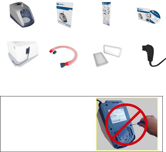
PACKAGE CONTENTS
AIRVO 2 humidifier |
AIRVO 2 User Manual |
AIRVO 2 Swingtag |
AIRVO 2 DVD |
(PT101xx) |
|
|
|
Oxygen inlet extension kit |
Disinfection Kit |
Air filter (x2) |
Power cord |
(900PT422) |
(900PT600) |
(900PT913) |
(900PT410xx) |
WARNING
UNDER NO CIRCUMSTANCES SHOULD THE
AIRVO 2 BE OPENED OR ANY OF THE SIX
FASTENING SCREWS ON THE UNDERNEATH
SIDE OF THE DEVICE BE LOOSENED.
OPENING THE UNIT WILL AFFECT THE
OXYGEN SEALS INSTALLED INSIDE, WHICH
WILL COMPROMISE THE SAFETY OF THE
DEVICE.
4
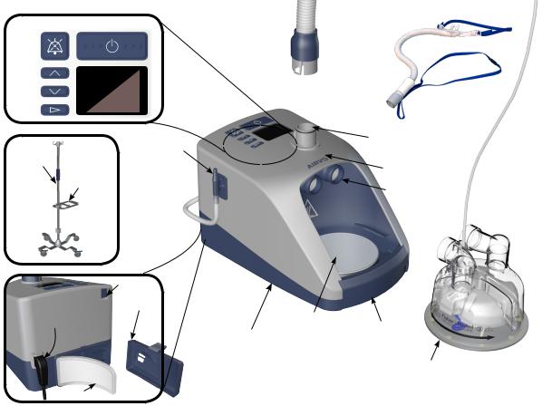
AIRVO 2 AND ACCESSORIES
|
|
|
|
Patient |
MUTE ON/OFF (STANDBY) |
interface |
|||
|
||||
|
|
|
|
Heated |
|
|
|
|
breathing |
UP |
|
|
|
tube |
|
DISPLAY |
|
||
DOWN |
|
|
|
|
|
|
|
|
|
MODE |
|
|
|
HEATED BREATHING TUBE |
|
|
|
||
|
|
|
|
|
|
|
|
OXYGEN |
CONNECTION PORT |
HOSPITAL |
|
|
|
|
|
|
INLET PORT |
MEASUREMENT POINT OF |
|
STAND |
|
|
|
|
|
POLE |
|
DISPLAYED DEW POINT |
|
|
MOUNTING |
|
TEMPERATURE |
|
TRAY
CHAMBER PORTS
Water chamber
SERIAL PORT
POWER CORD FILTER COVER
and |
HEATER |
|
CONNECTOR |
||
PLATE |
||
|
AIRVO2
(PT101xx)
AIR FILTER
FINGER
GUARD
AUTO-FILL WATER CHAMBER (MR290) (with adapter fitted)
5
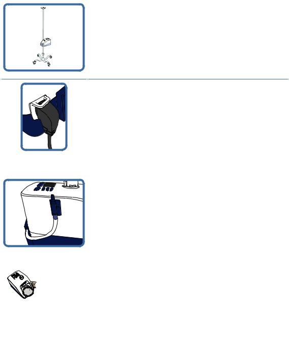
2. SETTING UP AIRVO 2 FOR FIRST USE
1. REMOVE THE AIRVO 2 FROM ITS PACKAGING
Place the AIRVO 2 on the 900PT405 pole mounting tray, on the 900PT421 hospital stand.
2. CONNECT THE POWER CORD
Plug the power cord connector into the socket on the back of the
AIRVO 2.
3. ATTACH THE OXYGEN INLET EXTENSION KIT
Refer to the instruction sheet included with the kit itself.
4. ATTACH WATER CHAMBER AND HEATED BREATHING TUBE
The water chamber and heated breathing tube must be connected to carry out the following setup and testing procedures.
If you have not been supplied with a reusable HC360 water chamber, you can use an MR290 chamber instead.
6
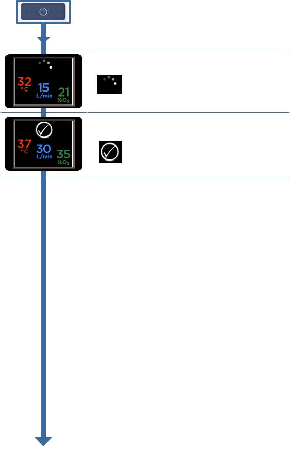
5. SWITCH ON UNIT
Switch on the unit by pressing the On/Off button.
6. WARM-UP
The unit will begin to warm up.
“Warm-up” symbol
7. READY FOR USE
The “Ready for use” symbol means that the system is ready for the patient to use.
“Ready for use” symbol
7

ADVANCED SETTINGS
When you see the “Warm-up” or “Ready for use” symbols, hold a combination of three buttons (Up, Down and Mute) for 5 seconds, to view and change advanced settings.
This button combination is for use by clinical engineering / technical personnel only.
AIRVO 2 / myAIRVO 2 MODE
You can change the unit from “AIRVO” (hospital) mode to “myAIRVO” (home / long-term care) mode, eg. for patients going home.
Contact Fisher & Paykel Healthcare for a myAIRVO 2 User Manual.
To change the mode:
Hold the Up and Down buttons for 3 seconds to “unlock” the setting.
Use the Up button to select myAIRVO 2.
Press the Mode button to confirm the change and/or move on to the next screen. Note that the unit will reset itself if it is switched between AIRVO 2 and myAIRVO 2 modes.
LANGUAGE
You can set the AIRVO 2 / myAIRVO 2 to one of 22 language settings:
English |
Nederlands |
Svenska |
|
Polski |
pl |
العربية |
ar |
Deutsch |
Português |
|
[simp.] |
Русский |
ru |
Türkçe |
tr |
Español |
Dansk |
|
[trad.] |
עברית |
he |
|
|
Français |
Suomi |
|
|
Ελληνικά |
el |
|
|
Italiano |
Norsk |
|
|
Română |
ro |
|
|
To change the language:
Hold the Up and Down buttons for 3 seconds to “unlock” the setting.
Use the Up and Down buttons to select the desired language.
Press the Mode button to confirm the change and/or move on to the next screen.
8
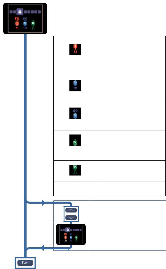
ENVIRONMENT SETTINGS (FOR DEFAULT MODE)
A clinician may change the “Environment Settings”, to customise individual AIRVOs for different environments (eg. intensive care, general care areas, emergency departments). The “Environment Settings”
95chosen will put limits on the “Patient Settings” that the operator can choose when in normal use.
This screen defines the “Environment Settings” for the AIRVO 2 when in Default Mode (ie. non-“Junior Mode”).
Minimum dew-point |
The lowest target dew-point temperature that |
temperature (°C) |
the operator will be able to select. |
|
Possible Settings: 31, 34, 37 °C |
|
If this is set to 31, the operator can select a target |
|
dew-point temperature between 31 and 37. ie. 31, |
|
34 or 37 (°C). |
|
If the patient is tracheostomised, a clinician may |
|
wish to set this value to 37, so that the operator |
|
can only select a target dew-point temperature |
|
between 37 and 37, ie. only 37 (°C). |
|
Note: The maximum dew-point temperature |
|
setting is always 37 °C in Default Mode. |
Minimum flow (L/min) |
The lowest flow that the operator will be able to |
|
select. |
|
Possible Settings: 10 to 60 in increments of 5 L/min, |
|
always less than or equal to Maximum Flow setting. |
|
Example: If this is set to 10, the operator will be |
|
able to select flows down to 10 L/min. |
|
If this is set to 25, the operator will be able to |
|
select flows down to 25 L/min. |
Maximum flow (L/min) |
The highest flow that the operator will be able |
|
to select. |
|
Possible Settings: 10 to 60 in increments of 5 L/min, |
|
always greater than or equal to Minimum Flow setting. |
|
Example: If this is set to 60, the operator can |
|
select flows up to 60 L/min. |
|
If this is set to 35, the operator can select flows up |
|
to 35 L/min. |
Maximum oxygen fraction (%) The highest oxygen fraction that the operator
95may set the unit to.
Possible settings: 30 - 100% in increments of 5% O2.
The unit will alarm if the measured oxygen fraction exceeds this value.
Note: Even if this ‘Maximum oxygen fraction‘ setting is set to 100%, any time the measured oxygen fraction exceeds 95%, the oxygen reading will pulse red and the device will beep.
Minimum oxygen fraction (%) The lowest oxygen fraction that the operator may set the unit to.
Possible settings: 21 or 25% O2.
When set to 25% the unit will alarm if the measured oxygen fraction is below this value. This allows detection of oxygen being disconnected.
Note that, for Oxygen display, this is a measurement only, not a control setting. The operator changes the measured oxygen fraction by altering the AIRVO 2 target flow setting and the flow of oxygen connected to the unit (e.g. from a flowmeter) - there is no closed-loop control.
To change the environment settings:
Hold the Up and Down buttons for 3 seconds to “unlock” the first setting.
Use the Up and Down buttons to change the setting,
95then press the Mode button to progress to the next setting.
Press the Mode button to confirm the change and/or move on to the
next screen. |
9 |
|

ENVIRONMENT SETTINGS (FOR JUNIOR MODE)
This screen defines the “Environment Settings” for the AIRVO 2 when in Junior Mode.
|
|
Junior Mode Enable/Disable |
|
When this option is enabled (default), the |
||
95 |
|
|
||||
|
|
|
|
|
|
operator can enter Junior Mode from the Home |
|
|
|
Enabled |
|
Screen, by holding the Mode button for 5 |
|
|
|
|
|
seconds. |
||
|
|
|
|
|
|
|
|
|
|
|
|
|
When this option is disabled, entering Junior |
|
|
|
Disabled |
|
mode is not possible. |
|
|
|
|
|
|
|
Consider disabling this option if the unit will never |
|
|
|
|
|
|
be used on pediatric patients. |
|
|
|
|
|
|
|
|
|
Dew-point |
|
The only dew-point setting in Junior Mode is |
||
|
|
temperature (°C) |
|
34 °C. |
||
|
|
|
|
|
|
|
|
|
Minimum flow (L/min) |
|
The lowest flow that the operator will be able to |
||
|
|
|
|
|
|
select. |
|
|
|
|
|
|
Possible Settings: 2 to 25 in increments of 1 L/min, |
|
|
|
|
|
|
always less than or equal to Maximum Flow setting. |
|
|
|
|
|
|
If this is set to 10, the operator will be able to |
|
|
|
|
|
|
select flows down to 10 L/min. |
|
|
|
|
|
|
|
|
|
Maximum flow (L/min) |
|
The highest flow that the operator will be able |
||
|
|
|
|
|
|
to select. |
|
|
|
|
|
|
Possible Settings: 2 to 25 in increments of 1 L/min, |
|
|
|
|
|
|
always greater than or equal to Minimum Flow setting. |
|
|
|
|
|
|
If this is set to 15, the operator can select flows up |
|
|
|
|
|
|
to 15 L/min. |
|
|
|
|
|
|
|
|
|
Maximum oxygen fraction (%) |
|
The highest oxygen fraction that the operator |
||
|
|
|
|
|
|
may set the unit to. |
|
|
|
95 |
|
|
|
|
|
|
|
|
Possible settings: 30 - 100% in increments of 5% O2. |
|
|
|
|
|
|
||
|
|
|
|
|
|
The unit will alarm if the measured oxygen |
|
|
|
|
|
|
fraction exceeds this value. |
|
|
|
|
|
|
Note: Even if this ‘Maximum oxygen fraction‘ |
|
|
|
|
|
|
setting is set to 100%, any time the measured |
|
|
|
|
|
|
oxygen fraction exceeds 95%, the oxygen reading |
|
|
|
|
|
|
will pulse red and the device will beep. |
|
|
|
|
|
|
|
|
|
Minimum oxygen fraction (%) |
|
The lowest oxygen fraction that the operator |
||
|
|
|
|
|
|
may set the unit to. |
|
|
|
|
|
|
Possible settings: 21 or 25% O2. |
|
|
|
|
|
|
When set to 25% the unit will alarm if the |
|
|
|
|
|
|
measured oxygen fraction is below this value. This |
|
|
|
|
|
|
allows detection of oxygen being disconnected. |
|
|
|
|
|
|
|
|
|
Note that, for Oxygen display, this is a measurement only, not a control setting. The |
||||
|
|
operator changes the measured oxygen fraction by altering the AIRVO 2 target |
||||
|
|
flow setting and the flow of oxygen connected to the unit (e.g. from a flowmeter) |
||||
|
|
- there is no closed-loop control. |
|
|||
|
|
|
|
|
|
|
To change the environment settings:
Hold the Up and Down buttons for 3 seconds to “unlock” the first setting.
Use the Up and Down buttons to change the setting, then press the Mode button to progress to the next setting.
Press the Mode button to confirm the change and/or move on to the next screen..
10
 Loading...