

Page 1
WITHOUT C
OAX *
WITH
COAX
1
(GB- '99)
TECHNICAL MANUAL
Edition 1999
9
VIDEO-INTERCOM SYSTEM
INDEX
Project monitors series
PuntoVirgola monitors series
Intercoms
Mody push-button panels
ErreP/R push-button panels
Power supply and control unit
Service modules
Video memory
Installation instructions
Working instructions
Troubleshooting
Installation diagrams WITH COAXIAL CABLE
Mody Videokit
Si 5000M One-way videokit with application of multipolar cable art.1304
One or multi-way diagrams
Si 5050 Video-intercom system with audio-video privacy
Si 5051 Multi-way combined intercom video-intercom system with audio-video privacy
Si 5150 Video-intercom system with two automatically switched entrances, one of which is only audio
Si 5250 Video-intercom system with two automatically switched video entrances
Si 5256 Video-intercom system with two automatically switched entrances, one with surveillance camera
Si 5350 Video-intercom system with three automatically switched video entrances
Si 5550 Multi-way video-intercom system with auxiliary audio entrances and one main video entrance according to
the stairway
Si 5551 Multi-way video-intercom system with auxiliary video entrances and one main video entrance according to
the stairway
- Working diagrams
- One way additional diagrams
- Multi-way additional diagrams
4+1 video-intercom system WITHOUT COAXIAL CABLE
Installation diagrams
Si 5800 One-way video-intercom system
Si 5801 Multi-way combined intercom and video-intercom system
Si 5850 Multi-way video-intercom system with two automatically switched entrances, one of which is only audio
Si 5851 Multi-way video-intercom system with two automatically switched video entrances
Page
2
8
11
12
21
23
24
25
26
28
29
30
31
31
32
33
35
37
39
41
43
45
47
48
50
54
55
60
60
61
62
63
Page 2
2
WITHOUT
COAX *
WITH COAX
(GB- '99)
Project series
* MODY *
ERREP/R
* PROJECT *
PUNTO
VIRGOLA * S
LIM
MONITORS
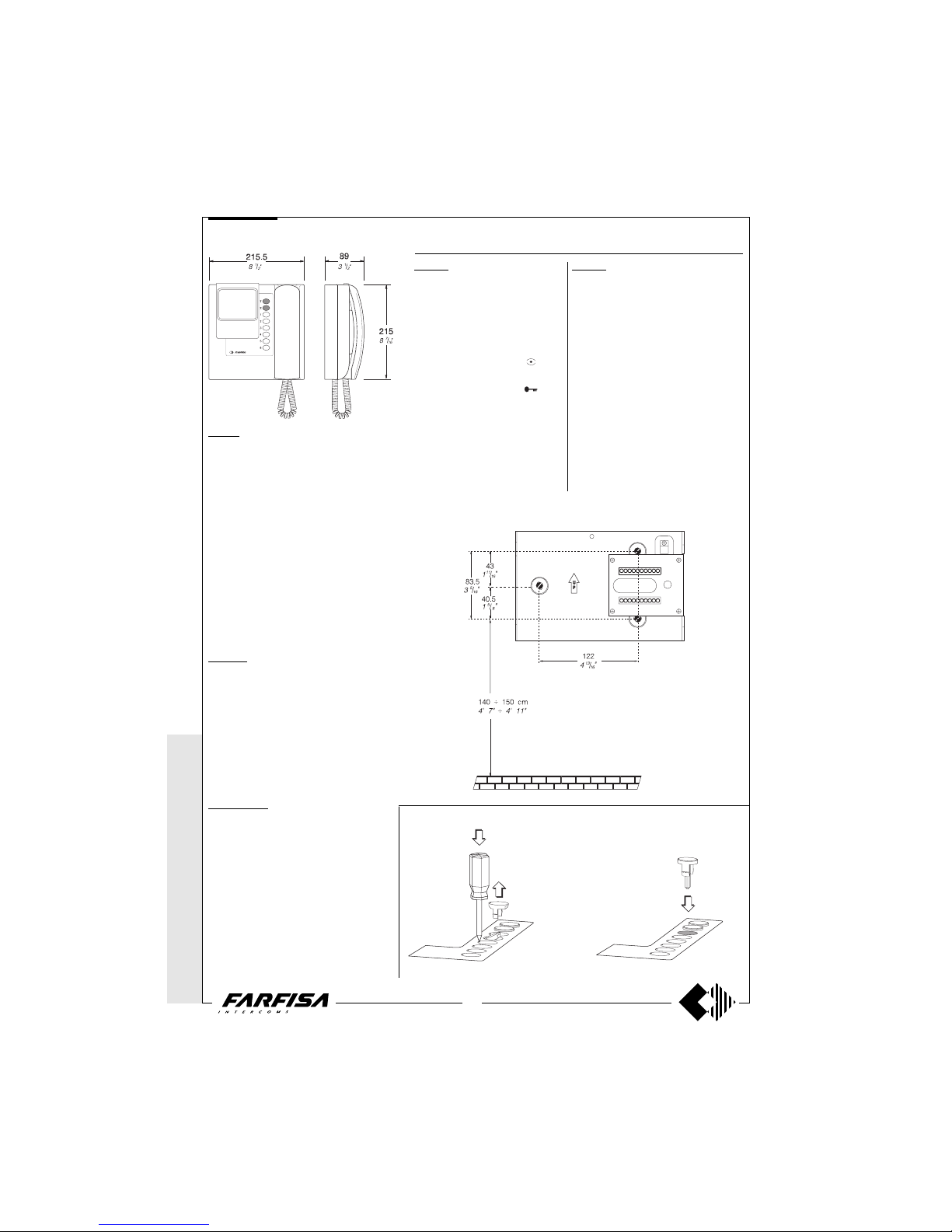
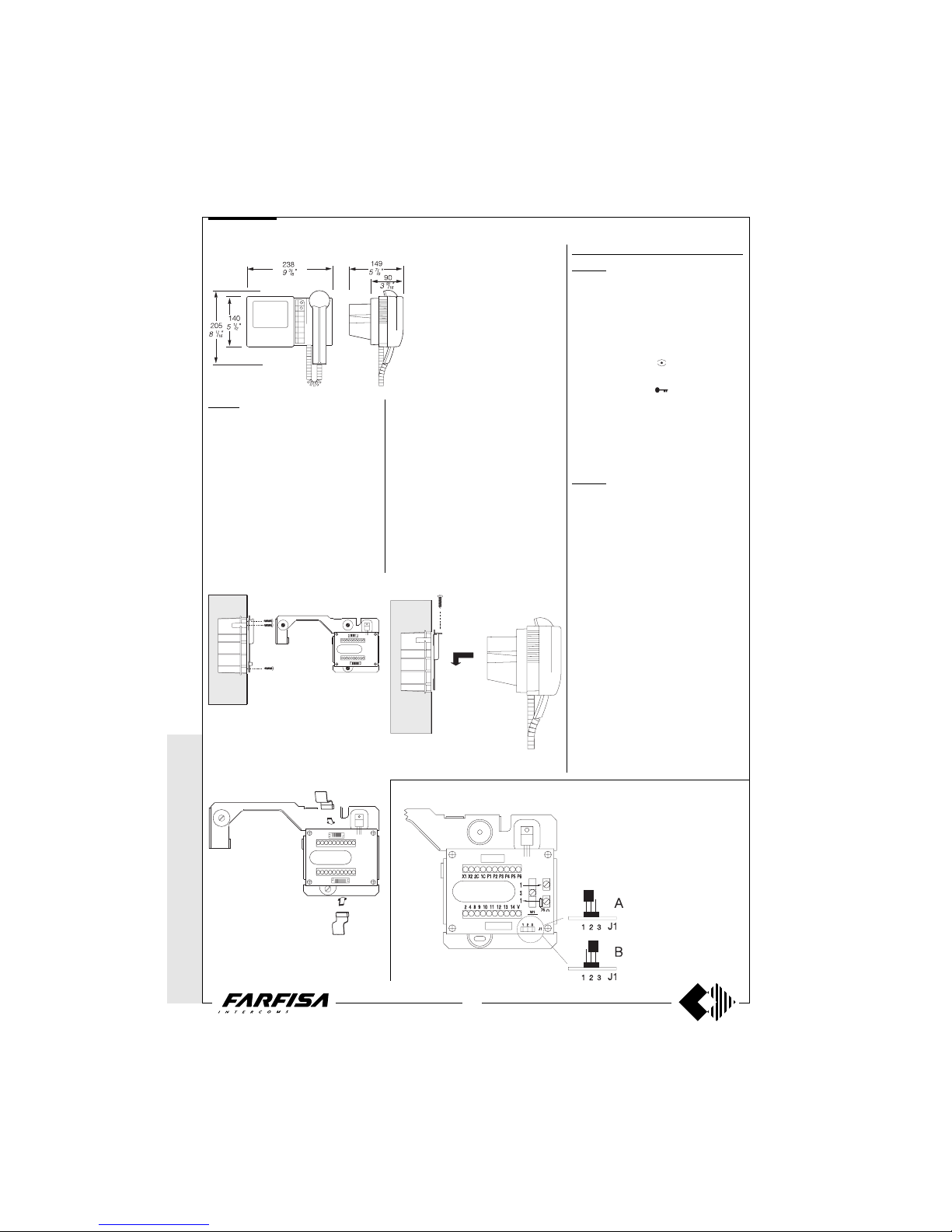
PT5160. Two-colour flat tube monitor with au-
dio-video privacy, electronic microphone, differentiated double electronic ringing sounds (modulated and continuous note) and terminal board
for the connection to the wall-bracket. With two
buttons, one for control switch ON and one for
door lock release, and 6 supplementary buttons,
that can be added for additional services such
as: control switch ON, intercommunicating calls,
stair lights, door lock release, etc.
The buttons are included in the kit of the monitor.
The maximum acceptable current to the button
terminals is 60mA. For higher currents use relay
unit art.1471.It can be installed on the wall (with
no built-in) by using the wall-bracket WB5100 or
WB5160. For particular needs it is possible to
separate the common of the buttons labeled P4,
P5 and P6 by cutting the W1 jumper on the wall-
bracket. The buttons have the 2C terminal in
common. In this case the maximum acceptable
current to the three buttons is 0.5A.
PT5160W. This model has the same features as
the previous one, but with a white finish.
Technical data
Power Supply 18÷24Vdc
Operating current 0.35A
Video tube 4" FLAT CRT
Television standard 625 lines
Horizontal frequency 15625Hz
Vertical frequency 50Hz
Bandwidth >5MHz
Video signal on 75Ω 0.8÷1.5Vpp
Starting up time 2÷4 sec.
Operating temperature 0°÷+50°C
Max. permissible humidity 90%RH
PT5160W-LCD. Version with colour LCD screen
monitor PT5160W.
Note: This version is applied to all video
installation diagrams with coaxial cable.
Technical data
Power Supply 18÷24Vdc
Operating current 0.4A
Screen 4" LCD
Television standard CCIR
Horizontal frequency 15625Hz
Vertical frequency 50Hz
Bandwidth >5MHz
Video signal on 75Ω 0.8÷1.5Vpp
Starting up time 1 sec.
Operating temperature 0°÷+50°C
Max. permissible humidity 90%RH
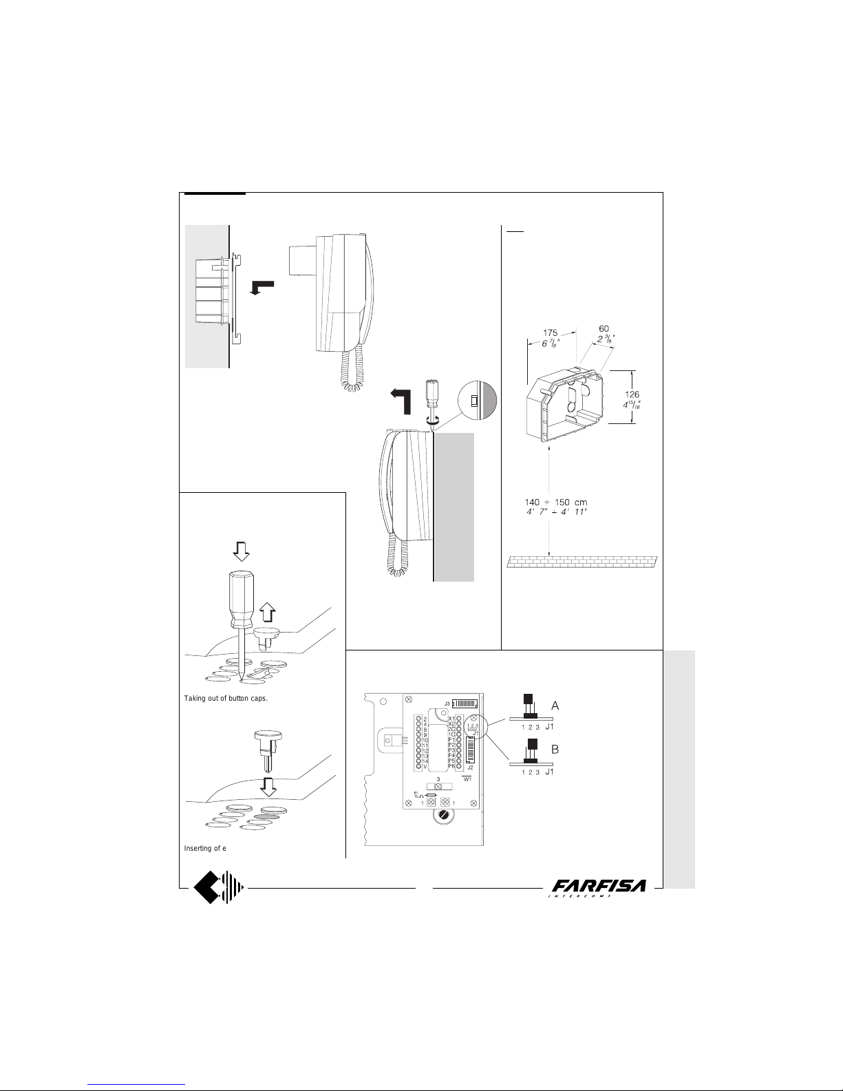
Measures for the installation of the wall bracket
WB5100 or WB5160 to the wall, and recommended height from the floor.
Supplementary push-buttons installation
WB5100. The wall bracket includes a
terminal board for connection to the
system, it is to be used when installing
2 - button monitors (control switch-ON
and door lock release), with a one call.
Terminals
1 Video signal input 0.8÷1.5Vpp
2 General ground
3 Video ground
4 Control switch ON - button
8 Positive power supply output for video
floor distributors 12Vdc
9 Door lock release - button
10 Call from the door station (180mA)
11 Audio ground
12 Microphone output
13 Speaker and automatic cancel
14 Positive power supply input 18÷24Vdc
V Not connected
WB5160. The wall bracket includes 2 termi-
nal boards for connection to the system, it is
to be used when installing monitors with extra
buttons and/or 2 differentiated bells.
Located on the wall-bracket terminal board is
a J1 jumper positioned for the intercommunicating service (position A).
By using the PT5160, PT5160W and
PT5160W-LCD monitors with multi-way systems without the intercommunicating service,
the audio privacy can be restored by positioning the jumper J1 in B.
Terminals
The terminals from 1 to 14 have the same functions and characteristics as the previous model.
V Activation input for digital systems
X1 AC power supply input 13Vac-0.35A
X2 Intercommunicating call input (ground com-
mand)
1C Common for P1, P2 and P3 buttons
2C Common for P4, P5 and P6 buttons
P1÷P6 Service buttons - max 60mA
Wall-brackets for the PT5160, PT5160W and PT5160W-LCD monitors.
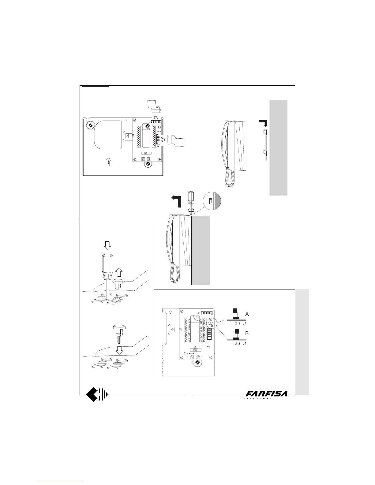
Taking out of button caps. Inserting of extra buttons.
Page 3
WITHOUT C
OAX *
WITH
COAX
3
(GB- '99)
Project series
* MODY * E
RREP/R *
PROJECT *
PUNTOVIRGOLA *
SLIM
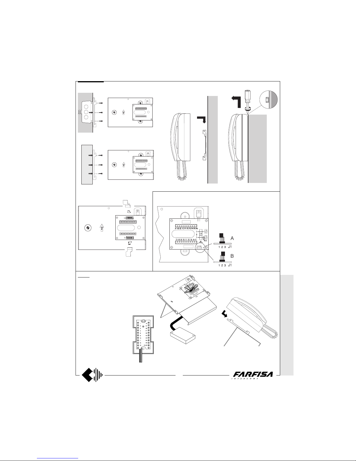
TA5160. Table adapter for monitors PT5160,
PT5160W and PT5160W-LCD.
With 20 wire connection cable, junction box
and bracket with 2 terminals board.
Terminals
The terminals have the same numbers, functions
and characteristics as those of wall bracket
WB5160.
Mounting instruction
Make the connection of the cable to
the terminals of the table adapter.
Make the connection of the conductors of the system to the junction box.
Plug-in the 2 flat cable to the table
adapter.
Fasten the monitor to the table
adapter.
WB 5160
TA 5160
Installation of the wall bracket WB5100 or
WB5160 to the wall, using a 83.5mm back
box and an expansion plug.
Dismounting of monitor from the wall bracket.
Audio privacy or intercommunicating service
Installation of monitor to the table adapter.
Installation of monitor onto the wall bracket.
Installation of the wall bracket WB5100
or WB5160 to the wall, by means of
expansion plugs.
Junction box.
MONITORS
Position for the intercommunicating service.
Position for the audio privacy.
Plugging in of monitor connectors to the terminal
boards of wall bracket.
Page 4
4
WITHOUT
COAX *
WITH COAX
(GB- '99)
* MODY *
ERREP/R
* PROJECT *
PUNTO
VIRGOLA * S
LIM
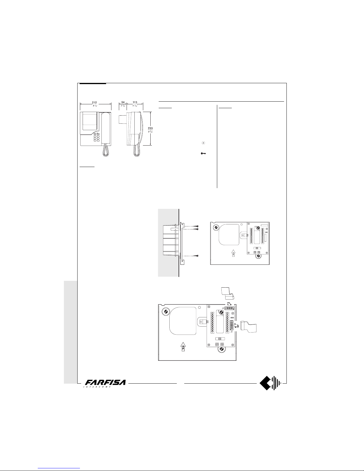
PT5660W. White colour monitor with tradi-
tional cathode tube with audio-video privacy,
electronic microphone, differentiated double
electronic ringing sounds (modulated and
continuous note) and terminal board for the
connection to the wall-bracket. With two buttons, one for control switch ON and one for
door lock release, and 6 supplementary buttons, that can be added for additional services such as: control switch ON, intercommunicating calls, stair lights, door lock release,
etc. The buttons are included in the kit of the
monitor. The maximum acceptable current to
the button terminals is 60mA. For higher
currents use relay unit art.1471.
It can be installed on the wall by using the
wall-bracket art.WB5600 or WB5660 and the
back-box art. 1283. For particular needs it is
possible to separate the common of the buttons labeled P4, P5 and P6 by cutting the W1
jumper on the wall-bracket. The buttons have
the 2C terminal in common. In this case the
maximum acceptable current to the three
buttons is 0.5A.
Technical data
Power Supply 18÷24Vdc
Operating current 0.6A
Video tube 4.5" - 90°
Television standard 625 lines
Horizontal frequency 15625Hz
Vertical frequency 50Hz
Bandwidth >5MHz
Video signal on 75Ω 0.8÷1.5Vpp
Starting up time 5÷7 sec.
Operating temperature 0°÷+50°C
Max. permissible humidity 90%RH
Project series
Installation of wall bracket WB5600 or WB5660 to the back box 1283.
Wall-brackets for the PT5660W monitor.
WB5600. The wall bracket includes a
terminal board for connection to the
system, it is to be used when installing
2 - button monitors (control switch-ON
and door lock release), with a one call.
Terminals
1 Video signal input 0.8÷1.5Vpp
2 General ground
3 Video ground
4 Control switch ON - button
8 Positive power supply output for video
floor distributors 12Vdc
9 Door lock release - button
10 Call from the door station (180mA)
11 Audio ground
12 Microphone output
13 Speaker and automatic cancel
14 Positive power supply input 18÷24Vdc
V Not connected
WB5660. The wall bracket includes 2 termi-
nal boards for connection to the system, it is
to be used when installing monitors with extra
buttons and/or 2 differentiated bells.
Located on the wall-bracket terminal board is
a J1 jumper positioned for the intercommunicating service (position A).
By using the PT5660W monitors with multiway systems without the intercommunicating
service, the audio privacy can be restored by
positioning the jumper J1 in B.
Terminals
The terminals from 1 to 14 have the same functions and characteristics as the previous model.
V Activation input for digital systems
X1 AC power supply input 13Vac-0.35A
X2 Intercommunicating call input (ground com-
mand)
1C Common for P1, P2 and P3 buttons
2C Common for P4, P5 and P6 buttons
P1÷P6 Service buttons - max 60mA
MONITORS
Plugging in of monitor connectors to the terminal boards of wall bracket.
Page 5
WITHOUT C
OAX *
WITH
COAX
5
(GB- '99)
Project series
* MODY * E
RREP/R *
PROJECT *
PUNTOVIRGOLA *
SLIM
WB 5660
1283. Back-box for monitors PT5660W and
PV1260.
Place the box on the wall at a height of about
1.5m (4' 11") from the floor keeping the front
edges flush-mounted and vertical to the finished plaster.
Supplementary push-buttons installation
Installation of monitor onto the wall bracket.
Dismounting of monitor from the wall
bracket.
MONITORS
Audio privacy or intercommunicating service
Position for the intercommunicating service.
Position for the audio privacy.
aaaaaaaaaaaaaaaaaaaa
Taking out of button caps.
Inserting of extra buttons.
Page 6

6
WITHOUT
COAX *
WITH COAX
(GB- '99)
* MODY * E
RREP/R *
PROJECT *
PUNTOVIRGOLA *
SLIM
PT5860. Two-colour reflex monitor with au-
dio-video privacy, electronic microphone, differentiated double electronic ringing sounds
(modulated and continuous note) and terminal board for the connection to the wallbracket. With two buttons, one for control
switch ON and one for door lock release, and
6 supplementary buttons, that can be added
for additional services such as: control switch
ON, intercommunicating calls, stair lights,
door lock release, etc. The buttons are included in the kit of the monitor. The maximum
acceptable current to the button terminals is
60mA. For higher currents use relay unit
art.1471.
It can be installed on the wall by using the
wall-bracket art.WB5600 or WB5660. For
particular needs it is possible to separate the
common of the buttons labeled P4, P5 and P6
by cutting the W1 jumper on the wall-bracket.
The buttons have the 2C terminal in common.
In this case the maximum acceptable current
to the three buttons is 0.5A.
PT5860W. This model has the same features
as the previous one, but with a white finish.
Technical data
Power Supply 18÷24Vdc
Operating current 0.6A
Video tube 4.5" - 90°
Television standard 625 lines
Horizontal frequency 15625Hz
Vertical frequency 50Hz
Bandwidth >5MHz
Video signal on 75Ω 0.8÷1.5Vpp
Starting up time 5÷7 sec.
Operating temperature 0°÷+50°C
Max. permissible humidity 90%RH
Project series
Measures for the installation of the wall bracket
WB5600 or WB5660 to the wall, and recommended
height from the floor.
Installation of the wall bracket WB5600 or WB5660 to the
wall, by means of expansion plugs.
Wall-brackets for the PT5860 and PT5860W monitors.
WB5660. The wall bracket includes 2 termi-
nal boards for connection to the system, it is
to be used when installing monitors with extra
buttons and/or 2 differentiated bells.
Located on the wall-bracket terminal board is
a J1 jumper positioned for the intercommunicating service (position A).
By using the PT5860 and PT5860W monitors
with multi-way systems without the intercommunicating service, the audio privacy can be
restored by positioning the jumper J1 in B.
Terminals
The terminals from 1 to 14 have the same functions and characteristics as the previous model.
V Activation input for digital systems
X1 AC power supply input 13Vac-0.35A
X2 Intercommunicating call input (ground com-
mand)
1C Common for P1, P2 and P3 buttons
2C Common for P4, P5 and P6 buttons
P1÷P6 Service buttons - max 60mA
WB5600. The wall bracket includes a
terminal board for connection to the
system, it is to be used when installing
2 - button monitors (control switch-ON
and door lock release), with a one call.
Terminals
1 Video signal input 0.8÷1.5Vpp
2 General ground
3 Video ground
4 Control switch ON - button
8 Positive power supply output for video
floor distributors 12Vdc
9 Door lock release - button
10 Call from the door station (180mA)
11 Audio ground
12 Microphone output
13 Speaker and automatic cancel
14 Positive power supply input 18÷24Vdc
V Not connected
MONITORS
Page 7
WITHOUT C
OAX *
WITH
COAX
7
(GB- '99)
Project series
* M
ODY * ERRE
P/R * PROJECT *
PUNTO
VIRGOLA *
SLIM
WB 5660
Supplementary push-buttons installation
Plugging in of monitor connectors to the terminal boards of wall bracket.
Dismounting of monitor from the wall bracket.
Installation of monitor onto the wall
bracket.
MONITORS
Position for the intercommunicating service.
Position for the audio privacy.
Audio privacy or intercommunicating service
Taking out of button caps.
Inserting of extra buttons.
Page 8
8
WITHOUT
COAX *
WITH COAX
(GB- '99)
PuntoVirgola series
* MODY *
ERREP/R
* PROJECT *
PUNTO
VIRGOLA * S
LIM
PV2160. Two-colour flat tube monitor with
audio-video privacy, electronic microphone,
differentiated double electronic ringing sounds
(modulated and continuous note) and terminal board for the connection to the wallbracket. With two buttons, one for control
switch ON and one for door lock release, and
5 supplementary buttons, that can be added
for additional services such as: control switch
ON, intercommunicating calls, stair lights,
door lock release, etc. The buttons are included in the kit of the monitor. The maximum
acceptable current to the button terminals is
60mA. For higher currents use relay unit
art.1471.It can be installed on the wall (with
no built-in) by using the wall-bracket WB2100
or WB2160. For particular needs it is possible to separate the common of the buttons
labeled T4 and T5 by cutting the W1 jumper
on the wall-bracket. The buttons have the 2C
terminal in common. In this case the maximum acceptable current to the three buttons
is 0.5A.
PV2160W. This model has the same features
as the previous one, but with a white finish.
Technical data
Power Supply 18÷24Vdc
Operating current 0.35A
Video tube 4" FLAT CRT
Television standard 625 lines
Horizontal frequency 15625Hz
Vertical frequency 50Hz
Bandwidth >5MHz
Video signal on 75Ω 0.8÷1.5Vpp
Starting up time 2÷4 sec.
Operating temperature 0°÷+50°C
Max. permissible humidity 90%RH
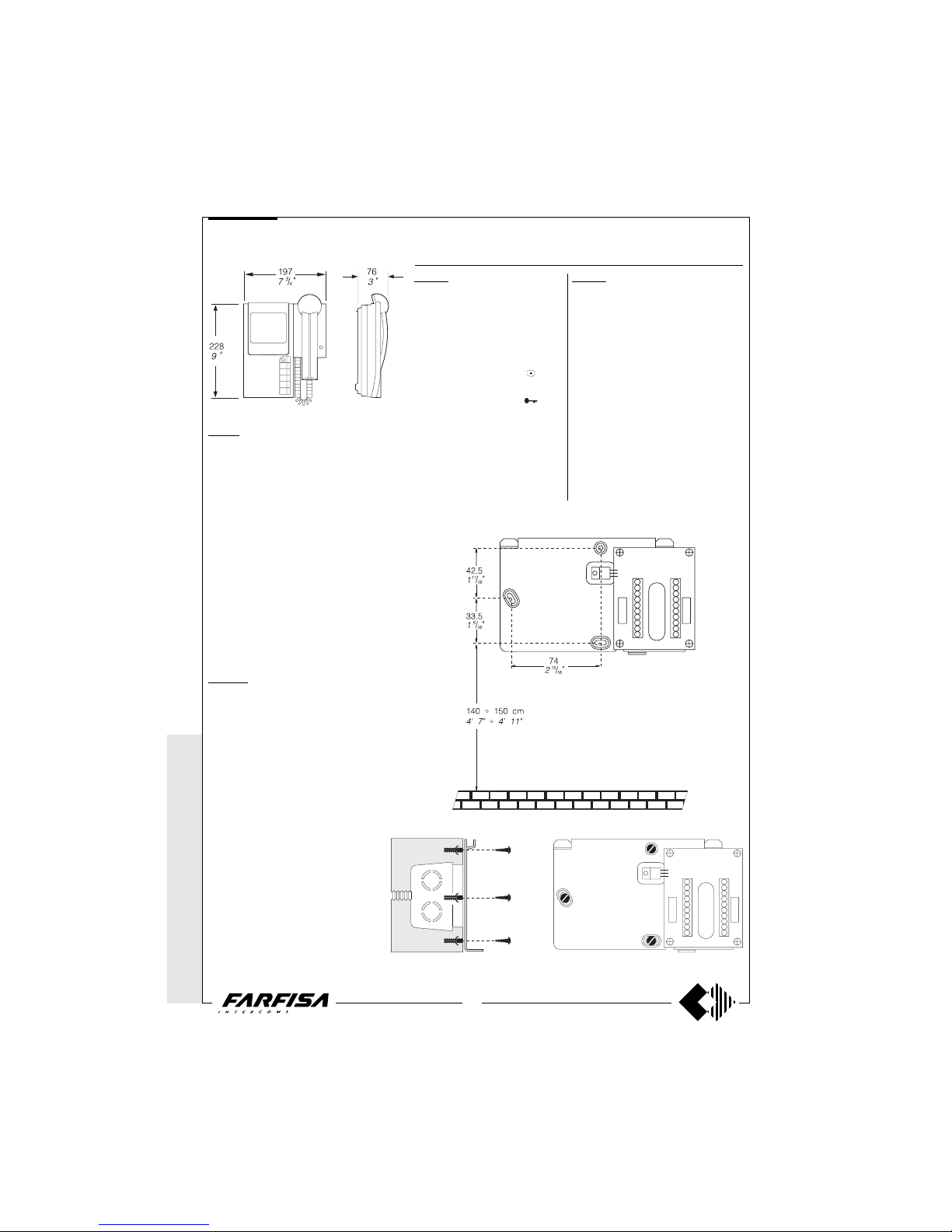
Measures for the installation of the wall bracket WB2100
or WB2160 to the wall, and recommended height from the
floor.
Installation of the wall bracket WB2100 or WB2160 to the wall, by means of
expansion plugs.
Wall-brackets for the PV2160 and PV2160W monitors.
WB2100. The wall bracket includes a
terminal board for connection to the
system, it is to be used when installing
2 - button monitors (control switch-ON
and door lock release), with a one call.
Terminals
1 Video signal input 0.8÷1.5Vpp
2 General ground
3 Video ground
4 Control switch ON - button
8 Positive power supply output for video
floor distributors 12Vdc
9 Door lock release - button
10 Call from the door station (180mA)
11 Audio ground
12 Microphone output
13 Speaker and automatic cancel
14 Positive power supply input 18÷24Vdc
V Not connected
WB2160. The wall bracket includes 2 termi-
nal boards for connection to the system, it is
to be used when installing monitors with extra
buttons and/or 2 differentiated bells.
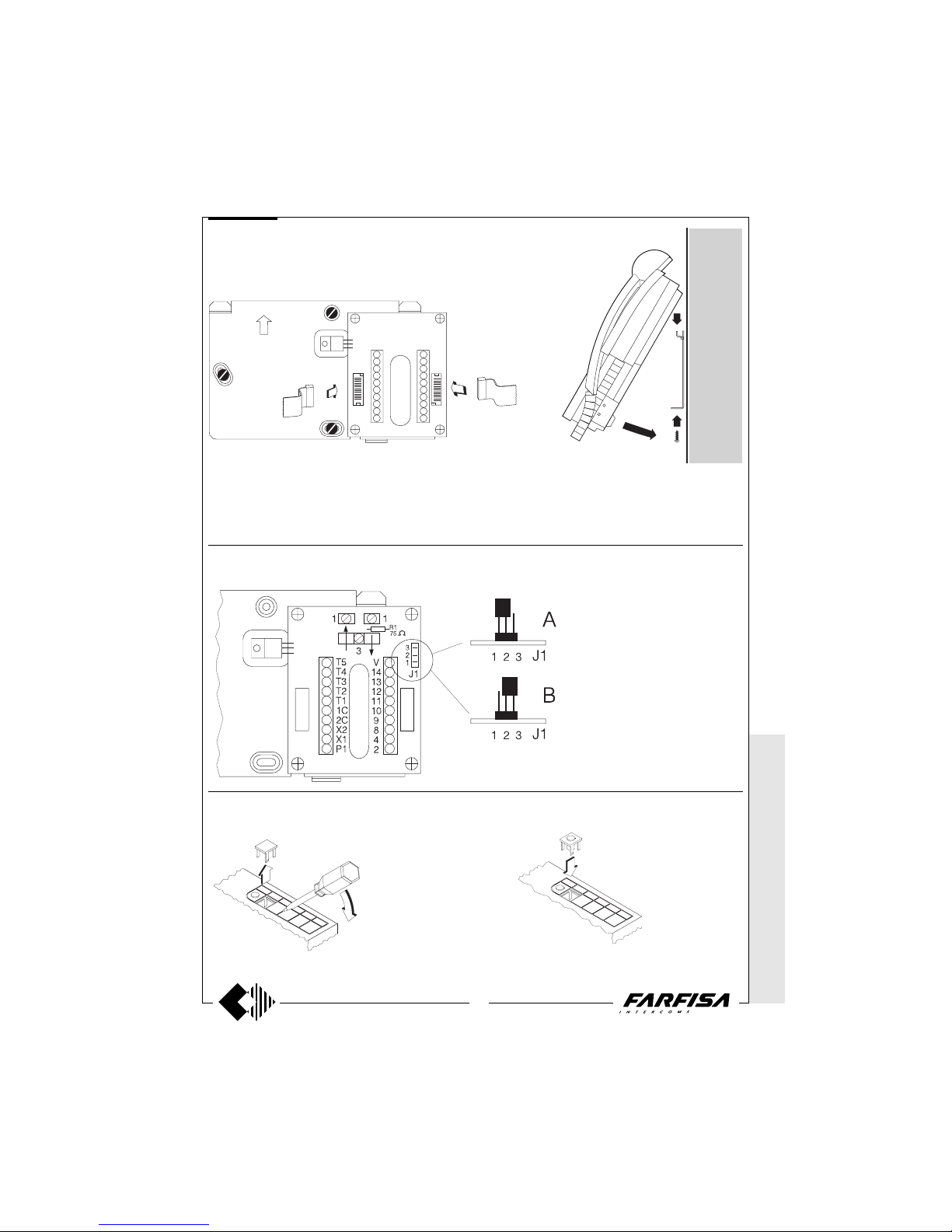
Located on the wall-bracket terminal board is
a J1 jumper positioned for the intercommunicating service (position A).
By using the PV2160 and PV2160W monitors
with multi-way systems without the intercommunicating service, the audio privacy can be
restored by positioning the jumper J1 in B.
Terminals
The terminals from 1 to 14 have the same functions and characteristics as the previous model.
V Activation input for digital systems
X1 AC power supply input 13Vac-0.35A
X2 Intercommunicating call input (ground com-
mand)
1C Common for T1, T2 and T3 buttons
2C Common for T4 and T5 buttons
T1÷T5 Service buttons - max 60mA
P1 Not connected
MONITORS
Page 9
WITHOUT C
OAX *
WITH
COAX
9
(GB- '99)
PuntoVirgola series
* MODY *
ERREP/R
* PROJECT *
PUNTOV
IRGOLA * SLIM
Installation of monitor onto the wall bracket.
U
P
J2 J3
Plugging in of monitor connectors to the terminal boards of wall bracket.
MONITORS
WB2160
Position for the intercommunicating service.
Position for the audio privacy.
Audio privacy or intercommunicating service
Supplementary push-buttons installation
Taking out of button caps.
Inserting of extra buttons.
Page 10
10
WITHOUT
COAX *
WITH COAX
(GB- '99)
PuntoVirgola series
* MODY * E
RREP/R *
PROJECT *
PUNTOVIRGOLA *
SLIM
MONITORS
PV1260. Two-colour monitor with traditional
cathode tube with audio-video privacy, electronic microphone, differentiated double electronic ringing sounds (modulated and a continuous note) and terminal board for the connection to the wall-bracket. With 2 buttons,
one for control switch ON and the other for
door lock release and 6 supplementary service buttons that can be added for additional
services such as: control switch ON, intercommunicating calls, stair lights, door lock
release, etc. The buttons are included in the
kit of the monitor. The maximum acceptable
current to the buttons is 60mA. For higher
currents use the art.1471 relay unit. It can be
installed on the wall using the wall-bracket
WB1200 or WB1260 and the back-box
art.1283.
Technical data
Power Supply 18÷24Vdc
Operating current 0.6A
Video tube 4.5"-90°
Television standard 625 lines
Horizontal frequency 15625Hz
Vertical frequency 50Hz
Band width >5MHz
Video signal on 75Ω 0.8÷1.5Vpp
Starting up time 5÷7 sec.
Operating temperature 0°÷+50°C
Max. permissible humidity 90%RH
Wall-brackets for the PV1260 monitor.
WB1200. The wall bracket includes a termi-
nal board for connection to the system, it is to
be used when installing 2 - button monitors
(control switch-ON and door lock release),
with a one call.
Terminals
1 Video signal input 0.8÷1.5Vpp
2 General ground
3 Video ground
4 Control switch ON -
button
8 Positive power supply output for video floor
distributors 12Vdc
9 Door lock release -
button
10 Call from the door station (180mA)
11 Audio ground
12 Microphone output
13 Speaker and automatic cancel
14 Positive power supply input 18÷24Vdc-0.6A
V Not connected
WB1260. The wall bracket includes 2 termi-
nal boards for connection to the system, it is
to be used when installing monitors with extra
buttons and/or 2 differentiated bells.
Located on the wall-bracket terminal board is
a J1 jumper positioned for the intercommunicating service (position A).
By using the PV1260 monitor with multi-way
systems without the intercommunicating service, the audio privacy can be restored by
positioning the jumper J1 in B.
Terminals
The terminals from 1 to 14 have the same functions and characteristics as the previous model.
V Activation input for digital systems
X1 AC power supply input 13Vac-0.35A
X2 Intercommunicating call input (ground com-
mand)
1C Common for P1, P2 and P3 buttons
2C Common for P4, P5 and P6 buttons
P1÷P6 Service buttons - max 60mA
Installation of wall bracket WB1200 or
WB1260 to the back box 1283.
Plugging in of monitor connectors to the terminal boards of
wall bracket.
Installation of monitor onto the wall bracket.
WB1260
Position for the intercommunicating service.
Position for the audio privacy.
Audio privacy or intercommunicating service
For particular needs it is possible to
separate the common of the buttons
labeled P4, P5 and P6 by cutting the
W1 jumper located on the connecting
terminal board. These buttons have in
common the C2 terminal. In this case
the maximum acceptable current to
the buttons is 0.5A.
Page 11
WITHOUT C
OAX *
WITH
COAX
11
(GB- '99)
PuntoVirgola series
MONITORS
Project series PuntoVirgola series
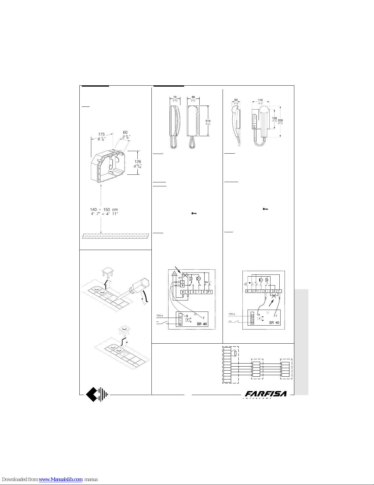
Note: In the intercoms it is necessary to cut
the jumper W1 which links terminals 3 and 7.
Note: In the intercoms it is necessary to take
out the jumper which links terminals 3 and 7.
1
3
1
4
8
9
10
11
12
13
14
2
75Ω
5
6
3
1
2
CT
5
6
3
1
2
CT
VC
Connection of 1 or max. 3 intercoms
parallel to the monitor.
These systems are not intercommunicating,
therefore all the models conceived for systems 4+1 can be used.
INTERCOMS
Supplementary push-buttons installation
Inserting of extra buttons.
Taking out of button caps.
1283. Back-box for PV1260 and PT5660W
monitors.
Place the box on the wall at a height of about
1.5m (4' 11") from the floor keeping the front
edges flush-mounted and vertical to the finished plaster.
* M
ODY * ERRE
P/R * PROJECT *
PUNTO
VIRGOLA *
SLIM
PT520. Two-colour intercom complete with
buzzer, spiral cord, electronic microphone
and 2 buttons that can be increased up to 10
by adding the single button unit art.PT501.
It can be installed on the wall with expansion
plugs or on a wall box.
PT520N. Colour: beige.
PT520W. Colour: white.
Terminals
1 microphone
2 loudspeaker
3 ground
5 door lock release button (max 1A)
6 buzzer (absorption 0.2A)
7 common push-buttons (
and 1)
9 electronic bell input
P1 service push-button (max 1A)
P2÷P9 service push-buttons (max 0.5A)
PT538. Table adaptor complete with ballast
base, connector, 13 wires cable. For all
Project intercoms.
PV260. Two-colour intercom complete with
buzzer, spiral cord, electronic microphone
and 2 buttons that can be increased up to 6 by
adding the single button unit art.SP10. It can
be installed on the wall with expansion plugs
or on a wall box.
PV260W. Colour: white.
Terminals
1 microphone
2 loudspeaker
3 ground
5 door lock release button (max 1A)
6 buzzer (absorption 0.2A)
7 common push-buttons (
and 1)
9 electronic bell input
P1 service push-button (max 1A)
P2÷P5 service push-buttons (max 0.5A)
TA60. Table adaptor complete with ballast
base, connector, 13 wires cable. For PV260
and PV260W intercoms.
Connection of the electronic bell SR40 inside
an intercom, Project series, to make intercommunicating calls.
Connection of the electronic bell SR40 inside
an intercom, PuntoVirgola series, to make
intercommunicating calls.
aaaaaaaaaaaaaaaaaaaa
Page 12
12
WITHOUT
COAX *
WITH COAX
(GB- '99)
* MODY *
ERREP/R
* PROJECT *
PUNTO
VIRGOLA * S
LIM
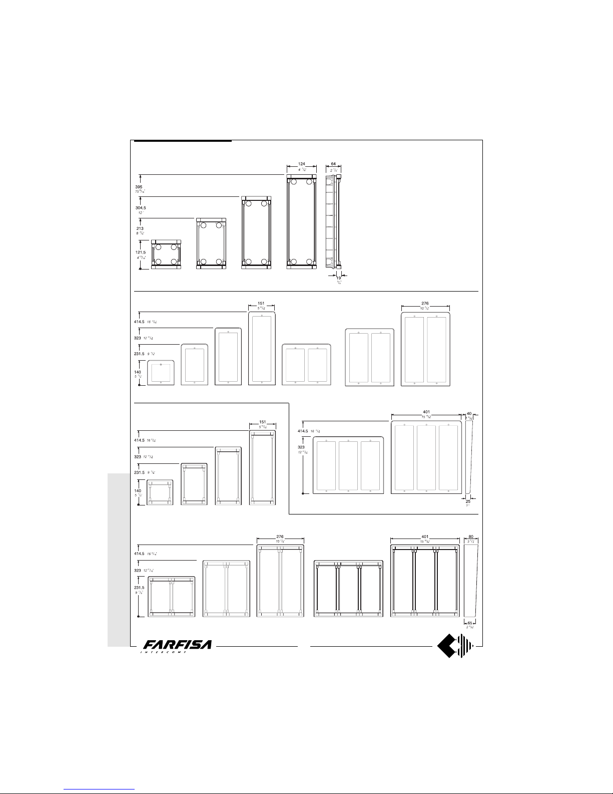
PUSH-BUTTON PANELS
Push-button panel in aluminium composed of
modular elements, able to resolve all installation
requirements. Back boxes, module frames, electric door speaker, camera, rain shelter and various
button modules are the basic elements in this
push-button panel line.
MD 71 MD 72 MD 73
MD 74
MD 81 MD 83
MD 804
MD 812MD 89
MD 82 MD 86 MD 808MD 84
MD 904MD 93MD 92MD 91
Rain shelter with module frames
Hood covers
Module frames complete with back box
MODY series
MD 94 MD 96 MD 908 MD 99 MD 912
Page 13
WITHOUT C
OAX *
WITH
COAX
13
(GB- '99)
* MODY * E
RREP/R *
PROJECT *
PUNTOVIRGOLA *
SLIM
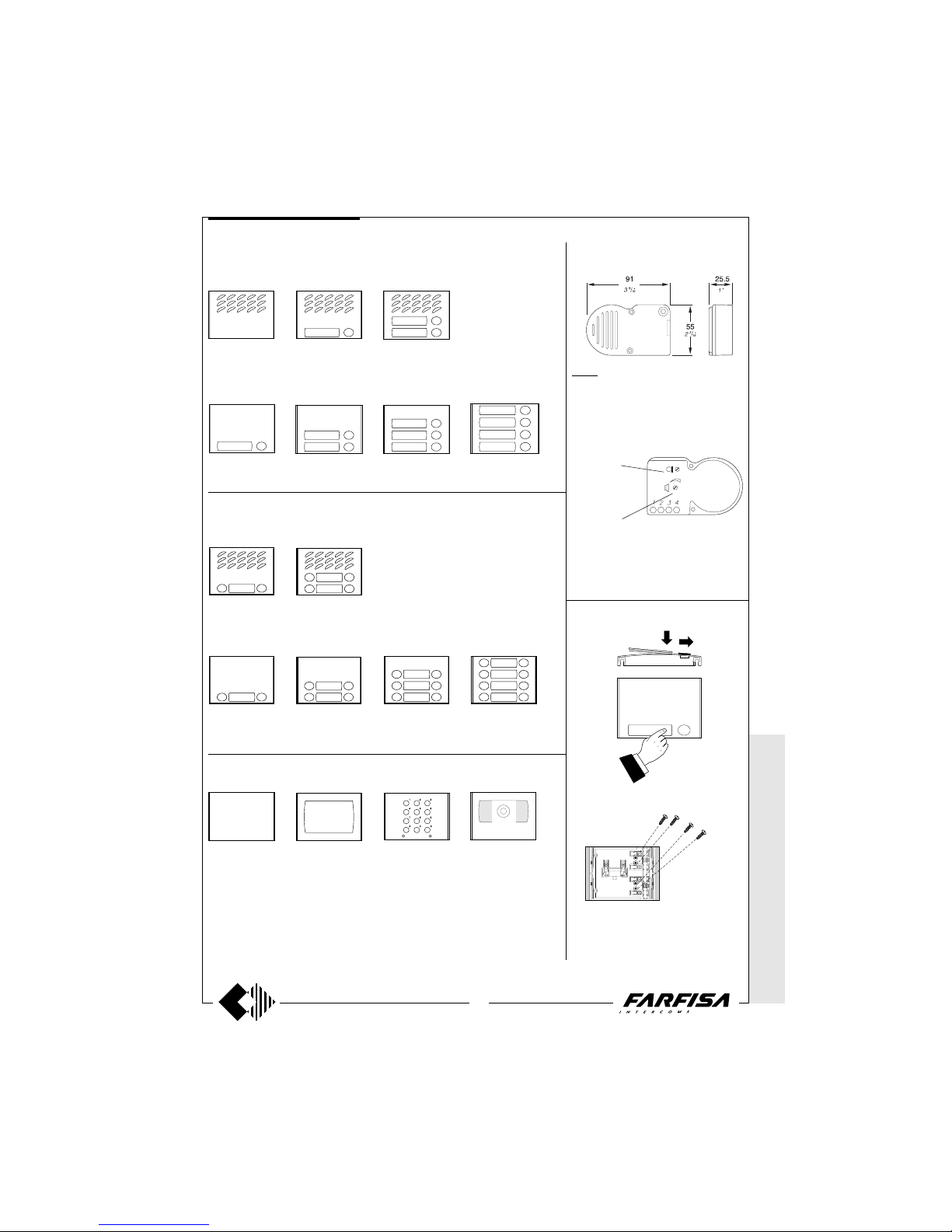
In any button module, to avoid the dismounting of name holder a screw 3MAx12 can be
inserted in the holes in order to block each
label.
Dismounting of name holder to insert name
label.
MD 10
Without call buttons
MD 11
1 call button
MD 12
2 call buttons
1 row push-button modules
Modules for electric door speaker (amplifier)
Button modules
MD 22
2 call buttons
MD 24
4 call buttons
MD 23
3 call buttons
MD 21
1 call button
2 row push-button modules
MD 122
2 call buttons
MD 124
4 call buttons
ELECTRIC DOOR-SPEAKER
(amplifier)
MD 30.
It consists of a double amplifier (receiver and
transmitter) with adjustable volume of 2
channels. Also fittable to ErreP/R and
Prestige push-button panels (for the ErreP/
R door stations by means of 299/1 adaptor).
Terminals
1 receiver
2 transmitter
3 positive power supply 6÷8Vdc - 60mA
4 ground
Dismounting and protection of name
labels
MD 222
2 call buttons
MD 224
4 call buttons
MD 226
6 call buttons
MD 228
8 call buttons
MD 20
Blank module
Modules: blank, number , access control and cameras
FC 52
Keypad module for
access control
(see page 20)
MD 50
Number module
50
MD40 B/W CCD camera
MD40C Colour CCD cam-
era (see page 20)
Button modules
Modules for electric door speaker (amplifier)
Receiver adjustable volume
Transmitter adjustable
volume
MODY series
PUSH-BUTTON PANELS
Page 14
14
WITHOUT
COAX *
WITH COAX
(GB- '99)
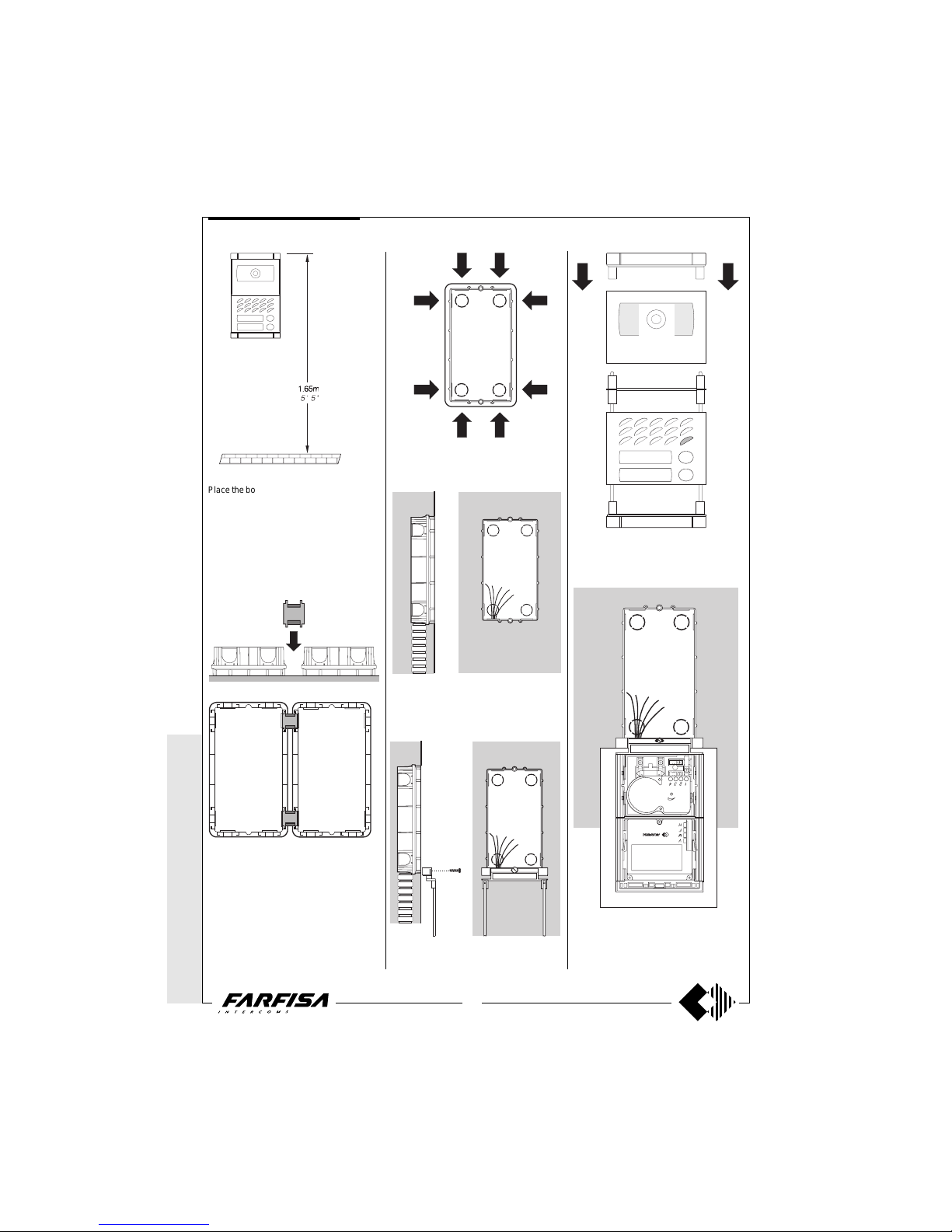
Place the box of the camera unit at a height of
about 1.65m from the floor keeping the front
edges flush-mounted and vertical to the finished plaster.
Position the camera unit in such a way that
solar rays or other direct light or intense
reflections do not hit the camera lens.
Insertion of cable bush between back boxes.
The cable bushes must be inserted before
brickwork.
Openings for cables.
Flush mounting and cables placing.
Mounting of button module.
Lower fixing of the module frame.
(a)
Lower fixing of the module frame on back box.
It is advised to insert a protection (a) between
panel and wall while fixing.
* MODY *
ERREP/R
* PROJECT *
PUNTO
VIRGOLA * S
LIM
MODY series
PUSH-BUTTON PANELS
Page 15
WITHOUT C
OAX *
WITH
COAX
15
(GB- '99)
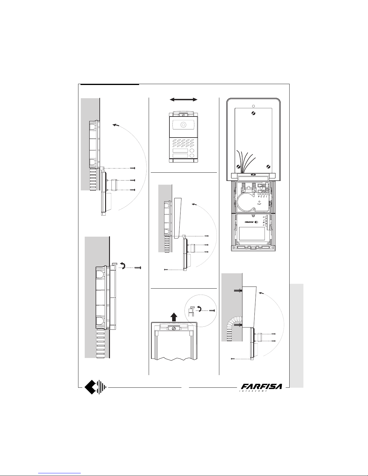
Mounting of frame bottom and door speaker
(amplifier).
Top fixing of the panel.
Alignment of the panel.
Hood covers
Dismounting of the frame top side from the
rain shelter.
Fixing of the hood cover between the back
box and the module frame.
Rain shelter
Modules insertion and wall fixing of rain shelter.
Mounting of the frame top to the rain shelter.
* MODY * E
RREP/R *
PROJECT *
PUNTOVIRGOLA *
SLIM
MODY series
PUSH-BUTTON PANELS
Page 16
16
WITHOUT
COAX *
WITH COAX
(GB- '99)
* MODY * E
RREP/R *
PROJECT *
PUNTOVIRGOLA *
SLIM
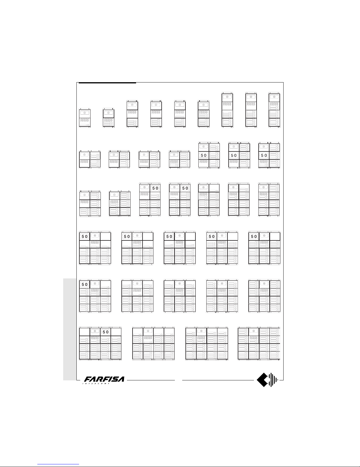
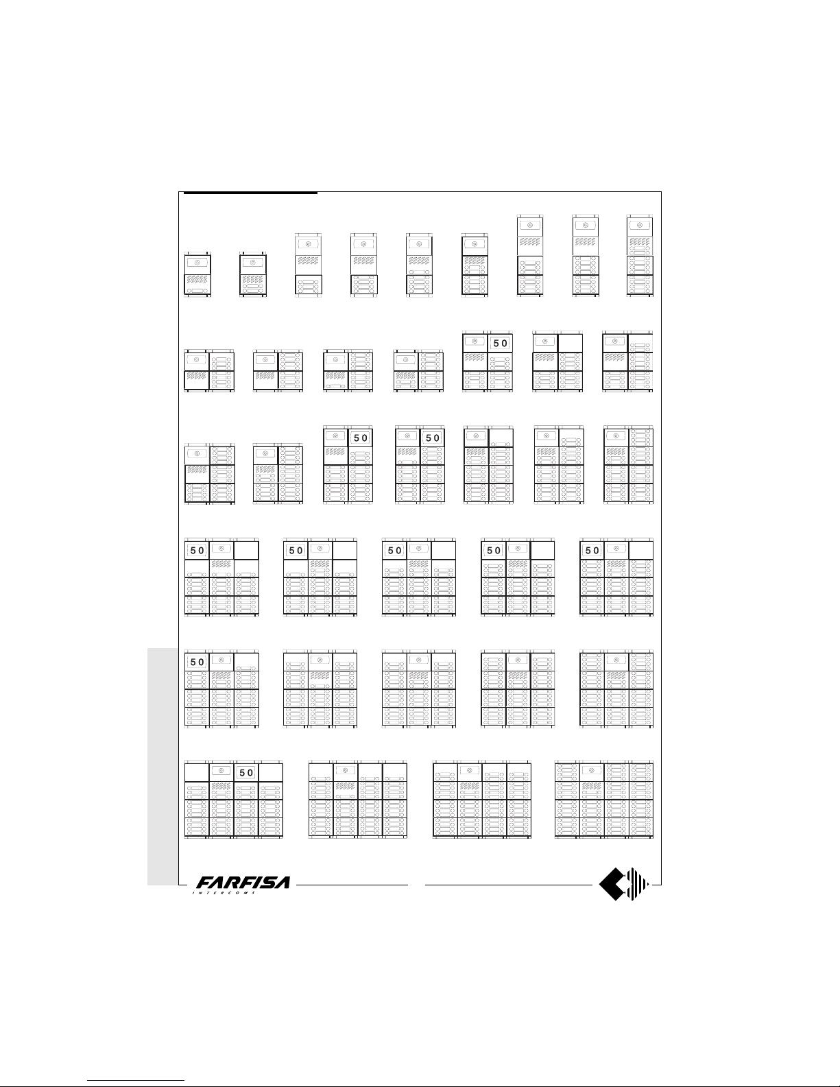
43 call buttons 58 call buttons
48 call buttons
52 call buttons
35 call buttons 40 call buttons37 call buttons
MODY series Example of Mody push-button panel installations.
42 call buttons38 call buttons
27 call buttons 32 call buttons28 call buttons 30 call buttons 34 call buttons
16 call buttons
7 call buttons 11 call buttons 12 call buttons
1 call button
2 call buttons
3 call buttons
10 call buttons
4 call buttons 5 call buttons 6 call buttons 7 call buttons 8 call buttons
8 call buttons 9 call buttons
10 call buttons 14 call buttons
26 call buttons
24 call buttons23 call buttons21 call buttons19 call buttons18 call buttons
1 row push-button
PUSH-BUTTON PANELS
Page 17
WITHOUT C
OAX *
WITH
COAX
17
(GB- '99)
* M
ODY * ERRE
P/R * PROJECT *
PUNTO
VIRGOLA *
SLIM
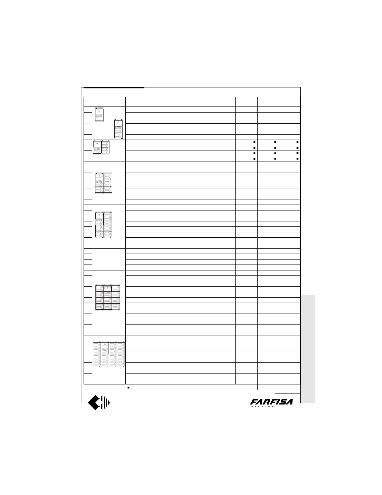
Composition board of Mody push-button panels.
Rain
shelter
Hood
covers
Back box and
module frame
Button and info or
blank modules
Module for
speaker
Door speaker
(amplifier)
Camera
module
Compositions and
dimensions
N°
calls
1 MD40
1 MD40
1 MD40
1 MD40
1 MD40
1 MD40
1 MD40
1 MD40
1 MD40
1 MD40
1 MD40
1 MD40
1 MD40
1 MD40
1 MD40
1 MD40
1 MD40
1 MD40
1 MD40
1 MD40
1 MD40
1 MD40
1 MD40
1 MD40
1 MD40
1 MD40
1 MD40
1 MD40
1 MD40
1 MD40
1 MD40
1 MD40
1 MD40
1 MD40
1 MD40
1 MD40
1 MD40
1 MD40
1 MD40
1 MD40
1 MD40
1 MD40
1 MD40
1 MD40
1 MD40
1 MD40
1 MD40
1 MD40
1 MD40
1 MD40
1 MD40
1 MD30
1 MD30
1 MD30
1 MD30
1 MD30
1 MD30
1 MD30
1 MD30
1 MD30
1 MD30
1 MD30
1 MD30
1 MD30
1 MD30
1 MD30
1 MD30
1 MD30
1 MD30
1 MD30
1 MD30
1 MD30
1 MD30
1 MD30
1 MD30
1 MD30
1 MD30
1 MD30
1 MD30
1 MD30
1 MD30
1 MD30
1 MD30
1 MD30
1 MD30
1 MD30
1 MD30
1 MD30
1 MD30
1 MD30
1 MD30
1 MD30
1 MD30
1 MD30
1 MD30
1 MD30
1 MD30
1 MD30
1 MD30
1 MD30
1 MD30
1 MD30
1 MD11
1 MD12
1 MD10
1 MD10
1 MD11
1 MD12
1 MD10
1 MD10
1 MD11
1 MD12
1 MD10
1 MD10
1 MD11
1 MD12
1 MD10
1 MD10
1 MD11
1 MD12
1 MD10
1 MD10
1 MD11
1 MD12
1 MD12
1 MD12
1 MD12
1 MD12
1 MD11
1 MD10
1 MD11
1 MD12
1 MD11
1 MD12
1 MD11
1 MD12
1 MD12
1 MD12
1 MD11
1 MD12
1 MD11
1 MD12
1 MD12
1 MD12
1 MD12
1 MD11
1 MD10
1 MD11
1 MD10
1 MD12
1 MD10
1 MD12
1 MD12
-
1 MD23
1 MD24
1 MD24
1 MD24
1 MD24
2 MD24
2 MD24
2 MD24
2 MD24
3 MD24
3 MD24
3 MD24
3 MD24
4 MD24
4 MD24
4 MD24
4 MD24
5 MD24
5 MD24
5 MD24
5 MD24
5 MD24
5 MD24
6 MD24
5 MD24
7 MD24
7 MD24
7 MD24
6 MD24
6 MD24
8 MD24
8 MD24
8 MD24
8 MD24
8 MD24
8 MD24
8 MD24
8 MD24
9 MD24
10 MD24
8 MD24
11 MD24
11 MD24
11 MD24
11 MD24
11 MD24
11 MD24
11 MD24
14 MD24
1 MD72
1 MD72
1 MD73
1 MD73
1 MD73
1 MD73
2 MD72
2 MD72
2 MD72
2 MD72
2 MD73
2 MD73
2 MD73
2 MD73
2 MD73
2 MD73
2 MD73
2 MD73
2 MD74
2 MD74
2 MD74
2 MD74
2 MD74
2 MD74
2 MD74
2 MD74
3 MD73
3 MD73
3 MD73
3 MD73
3 MD74
3 MD74
3 MD74
3 MD74
3 MD74
3 MD74
3 MD74
3 MD74
3 MD74
3 MD74
3 MD74
3 MD74
4 MD74
4 MD74
4 MD74
4 MD74
4 MD74
4 MD74
4 MD74
4 MD74
4 MD74
1 MD82
1 MD82
1 MD83
1 MD83
1 MD83
1 MD83
1 MD84
1 MD84
1 MD84
1 MD84
1 MD86
1 MD86
1 MD86
1 MD86
1 MD86
1 MD86
1 MD86
1 MD86
1 MD808
1 MD808
1 MD808
1 MD808
1 MD808
1 MD808
1 MD808
1 MD808
1 MD89
1 MD89
1 MD89
1 MD89
1 MD812
1 MD812
1 MD812
1 MD812
1 MD812
1 MD812
1 MD812
1 MD812
1 MD812
1 MD812
1 MD812
1 MD812
-
-
-
-
-
-
-
-
-
1 MD92
1 MD92
1 MD93
1 MD93
1 MD93
1 MD93
1 MD94
1 MD94
1 MD94
1 MD94
1 MD96
1 MD96
1 MD96
1 MD96
1 MD96
1 MD96
1 MD96
1 MD96
1 MD908
1 MD908
1 MD908
1 MD908
1 MD908
1 MD908
1 MD908
1 MD908
1 MD99
1 MD99
1 MD99
1 MD99
1 MD912
1 MD912
1 MD912
1 MD912
1 MD912
1 MD912
1 MD912
1 MD912
1 MD912
1 MD912
1 MD912
1 MD912
-
-
-
-
-
-
-
-
-
124x213x19
(47/8" x 8 3/8" x 3/4")
124x304,5x19
(47/8" x 12" x 3/4")
248x304.5x19
(9
3
/4" x 12" x
3
/4")
248x395x19
(9 3/4" x 15 9/16" x 3/4")
496x395x19
(19 1/2" x 15 9/16" x 3/4")
372x395x19
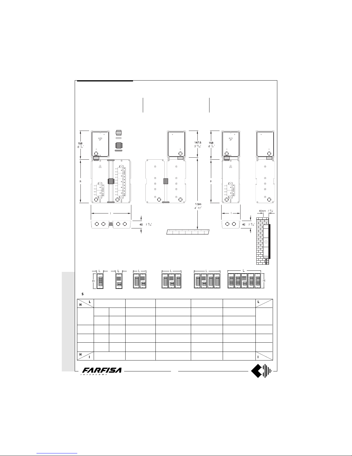
(14
5
/8" x
15 9/16"
x
3
/4")
* or MD20 or MD50 or FC52 Optional
It replaces
MD72, 73, 74
248x213x19
(9
3
/4" x 8 3/8" x
3
/4")
or MD74 or MD804 or MD904
1 row push-button
1
2
3
4
5
6
7
8
9
10
11
12
13
14
15
16
17
18
19
20
21
22
23
24
25
26
27
28
29
30
31
32
33
34
35
36
37
38
39
40
41
42
43
45
47
48
50
52
53
55
58
-
-
-
-
-
-
1 MD23
-
-
-
1 MD23
-
-
-
1 MD23
-
-
-
1 MD23
-
-
1 MD21
1 MD22
1 MD23
2 MD23
-
-
2 MD23
2 MD23
-
1 MD21
2 MD21
2 MD22
2 MD22
2 MD23
2 MD23
1 MD23
3 MD23
3 MD21
3 MD21
3 MD22
3 MD22
3 MD23
3 MD23
-
-
-
-
-
-
-
-
-
-
1*
1*
1*
1*
-
-
-
1*
1*
1*
1*
-
-
-
-
-
-
-
2*
2*
2*
2*
1*
-
-
-
-
-
-
3*
3*
-
-
-
-
-
-
-
372x304.5x19
(14
5
/8" x 12" x
3
/4")
MODY series
PUSH-BUTTON PANELS
Page 18
18
WITHOUT
COAX *
WITH COAX
(GB- '99)
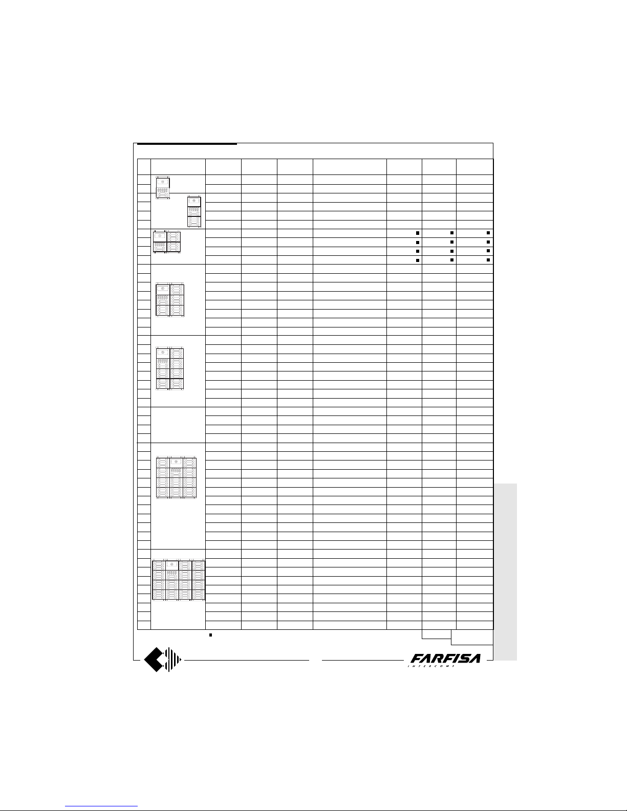
86 call buttons 116 call buttons
96 call buttons
104 call buttons
70 call buttons 80 call buttons74 call buttons 84 call buttons76 call buttons
54 call buttons 64 call buttons56 call buttons 60 call buttons 68 call buttons
32 call buttons
28 call buttons14 call buttons 20 call buttons16 call buttons
18 call buttons
22 call buttons 24 call buttons
2 call buttons
4 call buttons 6 call buttons 20 call buttons8 call buttons 10 call buttons 12 call buttons
* MODY * E
RREP/R *
PROJECT * P
UNTOVIRGOLA *
SLIM
52 call buttons48 call buttons46 call buttons42 call buttons38 call buttons36 call buttons
14 call buttons 16 call buttons
MODY series Example of Mody push-button panel installations.
2 row push-button
PUSH-BUTTON PANELS
Page 19
WITHOUT C
OAX *
WITH
COAX
19
(GB- '99)
* M
ODY * ERRE
P/R * PROJECT *
PUNTO
VIRGOLA *
SLIM
2
4
6
8
10
12
14
16
18
20
22
24
26
28
30
32
34
36
38
40
42
44
46
48
50
52
54
56
58
60
62
64
66
68
70
72
74
76
78
80
82
84
86
90
94
96
100
104
106
110
116
1 MD40
1 MD40
1 MD40
1 MD40
1 MD40
1 MD40
1 MD40
1 MD40
1 MD40
1 MD40
1 MD40
1 MD40
1 MD40
1 MD40
1 MD40
1 MD40
1 MD40
1 MD40
1 MD40
1 MD40
1 MD40
1 MD40
1 MD40
1 MD40
1 MD40
1 MD40
1 MD40
1 MD40
1 MD40
1 MD40
1 MD40
1 MD40
1 MD40
1 MD40
1 MD40
1 MD40
1 MD40
1 MD40
1 MD40
1 MD40
1 MD40
1 MD40
1 MD40
1 MD40
1 MD40
1 MD40
1 MD40
1 MD40
1 MD40
1 MD40
1 MD40
1 MD30
1 MD30
1 MD30
1 MD30
1 MD30
1 MD30
1 MD30
1 MD30
1 MD30
1 MD30
1 MD30
1 MD30
1 MD30
1 MD30
1 MD30
1 MD30
1 MD30
1 MD30
1 MD30
1 MD30
1 MD30
1 MD30
1 MD30
1 MD30
1 MD30
1 MD30
1 MD30
1 MD30
1 MD30
1 MD30
1 MD30
1 MD30
1 MD30
1 MD30
1 MD30
1 MD30
1 MD30
1 MD30
1 MD30
1 MD30
1 MD30
1 MD30
1 MD30
1 MD30
1 MD30
1 MD30
1 MD30
1 MD30
1 MD30
1 MD30
1 MD30
1 MD122
1 MD124
1 MD10
1 MD10
1 MD122
1 MD124
1 MD10
1 MD10
1 MD122
1 MD124
1 MD10
1 MD10
1 MD122
1 MD124
1 MD10
1 MD10
1 MD122
1 MD124
1 MD10
1 MD10
1 MD122
1 MD124
1 MD124
1 MD124
1 MD124
1 MD124
1 MD122
1 MD124
1 MD122
1 MD124
1 MD122
1 MD124
1 MD122
1 MD124
1 MD124
1 MD124
1 MD122
1 MD124
1 MD122
1 MD124
1 MD124
1 MD124
1 MD124
1 MD122
1 MD10
1 MD122
1 MD10
1 MD124
1 MD10
1 MD124
1 MD124
-
1 MD226
1 MD228
1 MD228
1 MD228
1 MD228
2 MD228
2 MD228
2 MD228
2 MD228
3 MD228
3 MD228
3 MD228
3 MD228
4 MD228
4 MD228
4 MD228
4 MD228
5 MD228
5 MD228
5 MD228
5 MD228
5 MD228
5 MD228
6 MD228
5 MD228
7 MD228
7 MD228
7 MD228
6 MD228
6 MD228
8 MD228
8 MD228
8 MD228
8 MD228
8 MD228
8 MD228
8 MD228
8 MD228
9 MD228
10 MD228
8 MD228
11 MD228
11 MD228
11 MD228
11 MD228
11 MD228
11 MD228
11 MD228
14 MD228
1 MD72
1 MD72
1 MD73
1 MD73
1 MD73
1 MD73
2 MD72
2 MD72
2 MD72
2 MD72
2 MD73
2 MD73
2 MD73
2 MD73
2 MD73
2 MD73
2 MD73
2 MD73
2 MD74
2 MD74
2 MD74
2 MD74
2 MD74
2 MD74
2 MD74
2 MD74
3 MD74
3 MD74
3 MD74
3 MD74
3 MD74
3 MD74
3 MD74
3 MD74
3 MD74
3 MD74
3 MD74
3 MD74
3 MD74
3 MD74
3 MD74
3 MD74
4 MD74
4 MD74
4 MD74
4 MD74
4 MD74
4 MD74
4 MD74
4 MD74
4 MD74
1 MD82
1 MD82
1 MD83
1 MD83
1 MD83
1 MD83
1 MD84
1 MD84
1 MD84
1 MD84
1 MD86
1 MD86
1 MD86
1 MD86
1 MD86
1 MD86
1 MD86
1 MD86
1 MD808
1 MD808
1 MD808
1 MD808
1 MD808
1 MD808
1 MD808
1 MD808
1 MD812
1 MD812
1 MD812
1 MD812
1 MD812
1 MD812
1 MD812
1 MD812
1 MD812
1 MD812
1 MD812
1 MD812
1 MD812
1 MD812
1 MD812
1 MD812
-
-
-
-
-
-
-
-
-
1 MD92
1 MD92
1 MD93
1 MD93
1 MD93
1 MD93
1 MD94
1 MD94
1 MD94
1 MD94
1 MD96
1 MD96
1 MD96
1 MD96
1 MD96
1 MD96
1 MD96
1 MD96
1 MD908
1 MD908
1 MD908
1 MD908
1 MD908
1 MD908
1 MD908
1 MD908
1 MD912
1 MD912
1 MD912
1 MD912
1 MD912
1 MD912
1 MD912
1 MD912
1 MD912
1 MD912
1 MD912
1 MD912
1 MD912
1 MD912
1 MD912
1 MD912
-
-
-
-
-
-
-
-
-
124x213x19
(47/8" x 8 3/8" x 3/4")
124x304,5x19
(47/8" x 12" x 3/4")
248x304.5x19
(9
3
/4" x 12" x
3
/4")
248x395x19
(9 3/4" x 15 9/16" x 3/4")
496x395x19
(19 1/2" x 15 9/16" x 3/4")
372x395x19
(14
5
/8" x
15 9/16"
x
3
/4")
* or MD20 or MD50 or FC52 Optional
It replaces
MD72, 73, 74
248x213x19
(9
3
/4" x 8 3/8" x
3
/4")
or MD74 or MD804 or MD904
-
-
-
-
-
-
-
-
-
1*
1*
1*
1*
-
-
-
1*
1*
1*
1*
-
-
-
-
-
-
-
2*
2*
2*
2*
1*
-
-
-
-
-
-
3*
3*
-
-
-
-
-
-
-
-
-
-
-
-
-
1 MD226
-
-
-
1 MD226
-
-
-
1 MD226
-
-
-
1 MD226
-
-
1 MD222
1 MD224
1 MD226
2 MD226
-
-
2 MD226
2 MD226
-
1 MD222
2 MD222
2 MD224
2 MD224
2 MD226
2 MD226
1 MD226
3 MD226
3 MD222
3 MD222
3 MD224
3 MD224
3 MD226
3 MD226
-
372x304.5x19
(14
5
/8" x 12" x
3
/4")
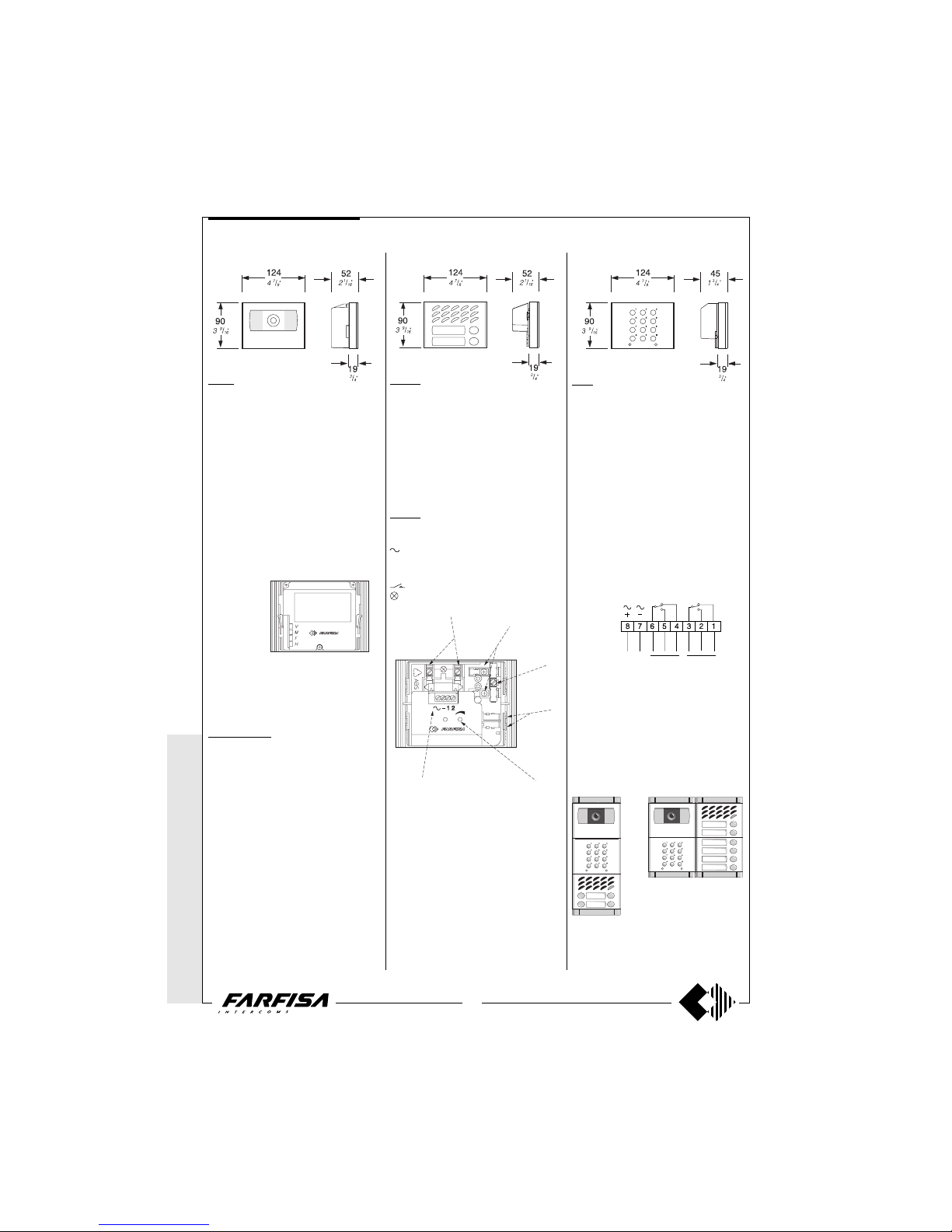
Composition board of Mody push-button panels.
Rain
shelter
Hood
covers
Back box and
module frame
Button and info or
blank modules
Module for
speaker
Door speaker
(amplifier)
Camera
module
Compositions and
dimensions
N°
calls
2 row push-button
MODY series
PUSH-BUTTON PANELS
Page 20
20
WITHOUT
COAX *
WITH COAX
(GB- '99)
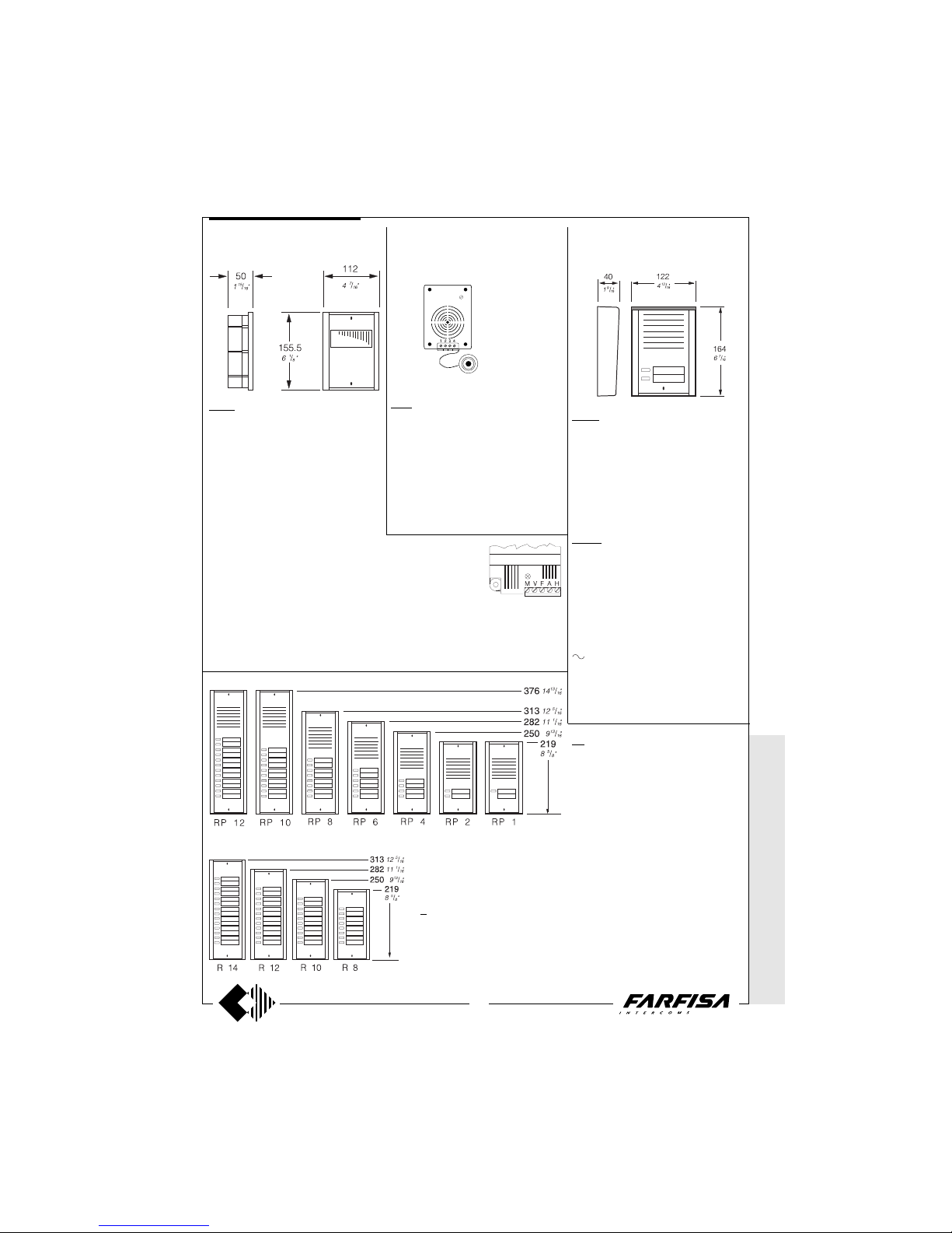
FC52.
Access control keypad with 12 digits and 2
relays for lock release. 4 programmable access codes for each relay. Programmable
door opening time from 1 up 99 sec. for each
relay (or bistable operation of one relay).
Acoustic confirmation for entered keys, accepted programmation and for wrong codes.
Power supply: 13VAC/DC-0.1A.
Dati tecnici
Power supply: 12Vac/dc ±10%
Stand-by current: 0.015A
Maximum current consumption: 0.1A
Contact ratings: 12VAC-5A.
Numbers of codes for relais 1: 4
Numbers of codes for relais 2: 4 or direct
activation
Activation time for each relay: from 1 to 99 sec.
(or bistable relay 1)
Operating temperature: 0° ÷ +40°C
Maximum permissible humidity: 85% RH
Terminals
1 normally closed contact of relais 2
2 normally open contact of relais 2
3 commun contact of relais 2
4 normally closed contact of relais 1
5 normally open contact of relais 1
6 commun contact of relais 1
7 ground or alternate voltage input
8 positive or alternate voltage input
Example of composition
MODY series
CAMERAS
Terminals
V video signal output
M ground
F not connected
H positive power supply input 21Vdc
MD 40C Colour.
This module includes:
- solid-state camera (CCD) with auto iris,
5.6mm fixed optics and 6 infrared-ray LED’s.
- front plate in anodized aluminium, with breakproof transparent screen.
Note: it is to be applied to all video installation
diagrams with coaxial cable.
Technical data
Power supply 21±3Vdc
Operating current 0.4A
Video signal on 75Ω 1Vpp
Minimum illumination 2.5 lux
Sensor CCD 1/3"
Gamma characteristic 0.45
White balance auto
Horizontal frequency 15625Hz
Vertical frequency 50Hz
Lens 5.6mm; F4
Adjustable focus 0.6m ÷
∞
Standard segnale video CCIR
Operating temperature -10°÷+40°
Maximum permissible humidity 80%RH
AMPLIFIED DOOR STATIONS
MD 100. 1 button module.
It can be applied to all systems 4+1, intercommunicating systems, and video-intercom systems with coaxial cable.
It includes electric door speaker, amplified in
the two channels, volume control of “receiver”,
“call” button and front plate in anodized aluminium. It can replace in many installations
module MD11 and MD30, using all the other
accessories of the Mody series.
For module installation, see the diagram on
page 32.
MD 200. 2 buttons module.
Terminals
- ground
supply 13Vac-60mA
1 receiver
2 transmitter
C call buttons common
call buttons
name-plate lamp (24V-70mA)
MD 40.
This module includes:
- solid-state camera (CCD) with auto iris,
3.6mm fixed optics and 6 infrared-ray LED’s.
- front plate in anodized aluminium, with breakproof transparent screen.
Technical data
Power supply 21±3Vdc
Operating current 0.2A
Video signal on 75Ω 1Vpp
Minimum illumination 2 lux
Sensor CCD 1/3"
Pixel number 291000
Horizontal frequency 15625Hz
Vertical frequency 50Hz
Lens 3.6mm; F5
Adjustable focus 0.1m ÷
∞
Opening of auto-iris
Operating temperature -10°÷+40°
Maximum permissible humidity 80%RH
1 Lamp terminals
2 Button terminal board
3 Call buttons common
4 Stair light button terminals
5 External volume adjustment
6 Terminal board for audio/powering
2
3
4
5
6
1
ACCESS CONTROL KEYPAD
* MODY *
ERREP/R
* PROJECT *
PUNTO
VIRGOLA * S
LIM
PUSH-BUTTON PANELS
Relay 1 Relay 2
Relais 1 Relais 2
13Vac
13Vdc
Page 21
WITHOUT C
OAX *
WITH
COAX
21
(GB- '99)
* MODY * E
RREP/R *
PROJECT *
PUNTOVIRGOLA *
SLIM
1385R.
The camera unit is used in the multi-way
video systems composed of:
- solid state camera (CCD) with auto iris,
3.6mm lens, infrared LEDs, electronic climatization and anti-clouding circuits
- anodized aluminium front plate complete
with transparent theft-proof screen
- back-box
- aluminium rain shelter
- key and safety screws for fixing the plate
Technical data
Power supply 21±3Vdc
Operating current 0.26A
Video signal on 75Ω 1Vpp
Minimum illumination 2 lux
Pixel number 291000
Horizontal frequency 15625Hz
Vertical frequency 50/60Hz
Lens 3.6mm; F5
Adjustable focus 0.1m ÷
∞
Opening of auto-iris
Operating temperature -10°÷+40°
Maximum permissible humidity 90%RH
RP. Push-button panels with anodized aluminium front panel and buttons, complete
with name plate lights and height adjustable
contacts to compensate imperfections of the
wall. The electric door speaker can be fitted
inside the push-button panel.
The unit should be flush-mounted and the
microphone should be firmly attached to
the front panel to avoid feedback and to
obtain the highest audio quality.
R. Push-button panels provided
only with buttons. An electric door
speaker cannot be fitted inside. When
such panels are installed together
with the previous ones, a system with
over 12 calls is obtained (see table on
page 22).
RP100. 1-button amplified door station.
It can be used in all one-way video-intercom
systems where the camera unit is separated
from the audio door station or where 1 or more
audio door stations are needed. It is complete
with an amplifier, in both channels, electric
door speaker, volume control, anodized aluminium call button and front panel, rain shelter and name plate light.
It can be installed on the wall with expansion
plugs or on a wall box.
RP 200. 2-button amplified door station.
Technical data
Power supply: 13Vac
Operating current: 130mA
Terminals
1 Receiver
2 Transmitter
C Common call buttons
P1 Call button
P2 Call button
- Ground
Alternate voltage input 13Vac
CAMERA UNIT ELECTRIC DOOR SPEAKER
(amplifier)
AMPLIFIED DOOR STATIONS
337C. It features a double amplifier (receiver
and transmitter); receiver has volume control. It is applicable inside the RP, NP or TM
push-button panels (or in other push-button
panels by means of the adaptor art.299).
Provided with an electret microphone and
tropicalized speaker.
Terminals
1 Receiver
2 Transmitter
3 Power supply 6÷8Vdc -60mA
4 Ground
ErreP/R - TM - NP/N series ErreP/R series
ErreP/R series
PUSH-BUTTON PANELS
Terminals
M Video ground (shield of coaxial cable)
V Video output signal 1Vpp (coaxial cable)
F General ground
A Alternate voltage input for name plate lights
and climatizing circuit 13Vac-40mA
H Positive power supply input for camera and
infrared LED’s 21±3Vdc-260mA
Page 22
22
WITHOUT
COAX *
WITH COAX
(GB- '99)
Instructions of the various ErreP/R push-button panel series and their dimensions en mm (and inches)
L and H = Dimensions of the panel l and h = Dimensions of the back-box
Installation notes
Among the back-box of the camera unit and
the push-button panel apply, before mounting
on to the wall, the tips and fair leads provided
in the kit.
Place the box of the camera unit at a height
of about 1.5m from the floor keeping the front
edges flush-mounted and vertical to the finished plaster.
Position the camera unit in such a way that
solar rays or other direct light or intense
reflections do not hit the camera lens.
Example of assembly of back-box with an uneven
number of ErreP/R push-button panel series
Example of assembly of the back-box with an even number of ErreP/R series
push-button panels
1385R 1385R 1385R 1385R
RP.. RP.. RP.. RP..R..
R..
* MODY *
ERREP/R
* PROJECT *
PUNTO
VIRGOLA * S
LIM
ErrreP/R series
PUSH-BUTTON PANELS
H
H
L
l l
L
Series R RP R+RP R+RP+R R+RP+R+R R+R+RP+R+R
112 (4
7
/16") 224 (8 13/16") 336 (13 1/4") 448 (17 5/8") 560 (22 1/16")
R8 RP1 R8+RP1=9 2R8+RP1=17 3R8+RP1=25 4R8+RP1=33
R8 RP2 R8+RP2=10 2R8+RP2=18 3R8+RP2=26 4R8+RP2=34
R10 RP4 R10+RP4=14 2R10+RP4=24 3R10+RP4=34 4R10+RP4=44
R12 RP6 R12+RP6=18 2R12+RP6=30 3R12+RP6=42 4R12+RP6=54
R14 RP8 R14+RP8=22 2R14+RP8=36 3R14+RP8=50 4R14+RP8=64
103 (4 1/16") 215 (8 7/16") 327 (12 7/8") 439 (17 5/16") 551 (21 11/16")
218.5
(8
5
/8")
250
(9
13
/16")
281.5
(11
1
/16")
313
(12
5
/16")
206.5
(8
1
/8")
238
(9
3
/8")
269.5
(10
5
/8")
301
(11
7
/8")
h
h
Template spacers and short
cable holder bushings.
Template spacers and long
cable holder bushings.
Page 23
WITHOUT C
OAX *
WITH
COAX
23
(GB- '99)
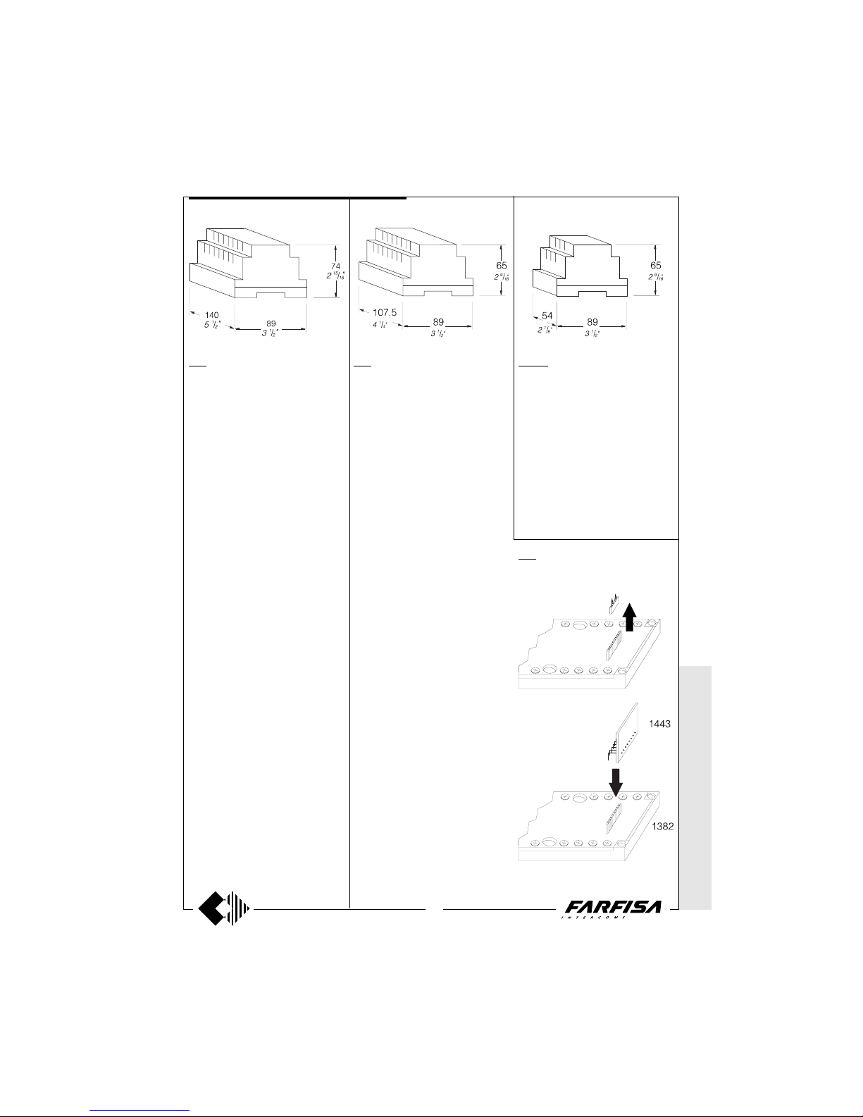
PRS210. TRANSFORMER.
It is used to power the amplified external
units MD100, MD200, RP100 and RP200,
additional door locks, name plate lights,
etc.
Technical data
Input voltage: 127V or 230Vac
Power: 15VA
Output voltage: 13Vac
Maximum current with direct use: 0.7A
Maximum current with intermitten: 1A
Housing: DIN 3 modules A
Weight: 0.42Kg
Approved: VDE
Operating temperature: 0° ÷ +50°C
Maximum permissible humidity: 90% RH
1382. AUDIO-VIDEO TIMER.
Connected to the stabilized power supply
art.1281, it allows a video-intercom system to
be timed (50 seconds).
It also allows time to be increased during a
conversation (3 minutes), automatic power
OFF at the end of the conversation; switching
ON of one monitor at a time. By adding the
intercommunicating module art.1443 on the
proper connector, an intercommunicating
operation with privacy towards the external
speaker is obtained.
Technical data
Turn ON time: -50 sec. with handset replaced
-3 min. with handset lifted
Operating temperature 0°÷+50°C
Maximum permissible humidity 90%RH
Housing DIN 6 modules A
Terminals
I Logic command output of timing 0/5Vdc
+ Positive voltage input 18÷28Vdc-2A
- Ground
A Alternating voltage input-output 13Vac-1.6A
D Alternating voltage output for the common of
pushbutton 13Vac-0.5A (intermittent service)
H Timed positive voltage output for the camera
unit 18÷28Vdc-0.5A max.
F Ground
1 Transmitter audio channel input 4.5Vdc-10mA
2 Receiver audio channel input 2Vdc-16mA
3 Positive voltage output 8Vdc-0.1A
S Electronic door lock release 1A
4 Control switching ON input from the monitors
5.5Vdc-90mA
9 Door lock release command 50mA
11 Audio ground
12
Transmitter audio channel output 4.5Vdc10mA
13 Receiver audio channel output 2Vdc-16mA
14 Timed positive voltage output for the monitors
18÷28Vdc-1.5A max.
1281. STABILIZED POWER SUPPLY WITH
SWITCHING REGULATOR.
Connected to the timer art.1382, allows to
drive at low voltage a monitor (or 2 in parallel
in FLAT type), a camera unit with a solid state
sensor (CCD), electric door lock, name plate
lights, etc.
Technical data
Input voltage 127 or 230Vac
Frequency 50/60Hz
Power 48VA
Operating temperature 0°÷+50°C
Maximum permissible humidity 90%RH
Housing DIN 8 modules A
Weight 0.95Kg.
Terminals
A Output voltage 13Vac for:
-name plate light, exchangers and climatized
camera (continuous service 0.6A)
-electric door lock and bells (intermittent
service 1A)
- Ground
+
Continuous output 21Vdc-1A (timed operation)
I Logic command input from timing
0 = activated
+5Vdc = non activated
Note
- The power supply is not provided with fuses,
but all of its outputs are protected against
overloading and short circuiting by temperature sensors. To reset the power supply, power must be cut off for about one minute and
can be restored after having eliminated the
defect.
- The power supply must be installed in a dry
place and can be fixed on DIN bar or on a wall
by using the expansion plugs.
- The connection between power supply 1281
and timer 1382 is not to be longer than 25cm.
POWER SUPPLY AND CONTROL UNIT
1443. Intercommunicating module.
Added inside the timer art.1382, it allows for
the intercommunicating function with privacy
towards the external speaker.
* MODY * E
RREP/R *
PROJECT *
PUNTOVIRGOLA *
SLIM
Page 24
24
WITHOUT
COAX *
WITH COAX
(GB- '99)
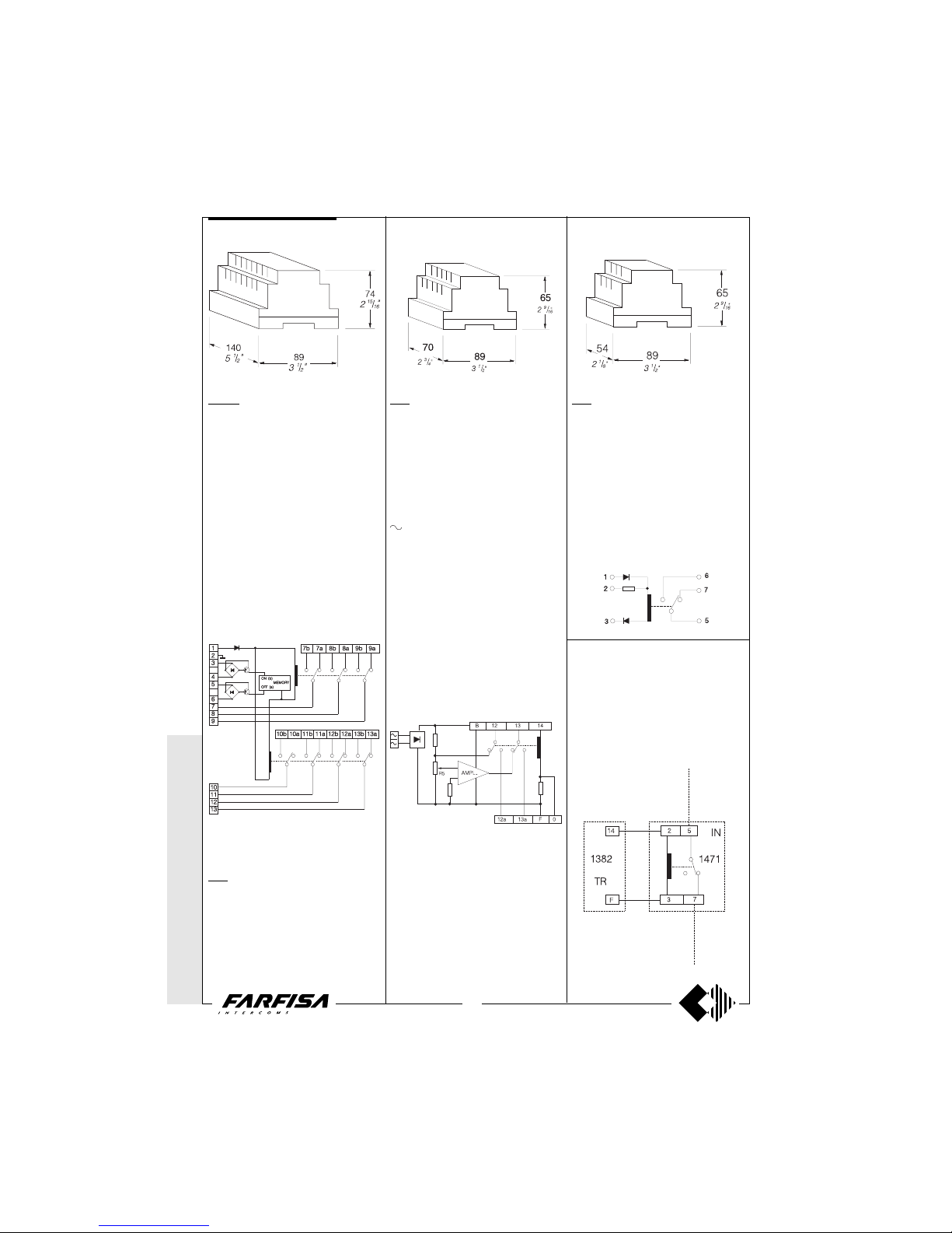
1273TV. EXCHANGER.
It is used in systems with 2 or more video
entrances for switching automatically the
video signals, the audio lines and door lock
on the calling entrance. Can be fixed on DIN
bar or with two expansion plugs. In housing
DIN 8 modules A. For the switching of video
signals it is advisable to use terminals 8-8a8b and 9-9a-9b, being that they are physically
closer.
Terminals
1 Power supply 13Vac-0.1A
2 Ground
3 and 4 Driver to switch the relay in “b” position
- ON position
5 and 6 Driver to switch the relay in “a” position
- OFF position
7, 8, 9, 10, 11, 12 and 13 Common relay contacts
7a, 8a, 9a, 10a, 11a, 12a and 13a OFF position
of the relay contacts
7b, 8b, 9b, 10b, 11b, 12b and 13b ON position
of the relay contacts
2443. RELAY AMPLIFIER FOR INTERCOMMUNICATING SYSTEMS.
It is suitable for video intercom systems where
it is necessary to have the intercommunicating service in different flats with privacy towards both outside and other users. Use
art.2443 in every intercommunicating flat.
Can be fixed on DIN bar or with two expansion
plugs. In housing DIN 4 modules A.
Terminals
F General ground
B Power supply 8Vdc-60mA
Power supply 13Vac-70mA
12 Connection toward the microphone of the
monitors
12a Audio output from door station (transmitter
channel)
13 Connection towards the speaker of the moni-
tors
13a Audio input from the door station (receiver
channel)
14 Timed power supply for the audio connec-
tion toward the door station 12÷24Vdc-60mA
0 From the jumper with F when the terminal 14
is powered to 12Vdc (terminal 8 of the monitor)
Note
If it is necessary to adjust the volume of the
intercommunicating audio turn trimmer R5.
1471. RELAY UNIT.
A low voltage, low current (DC/AC) unit, it
can switch voltages up to 50Vac/dc and 5A
max. Used for auxiliary services (e.g. stair
lights, call for 4 or more bells, door release
etc).
It installs on DIN bar or with two screws. In
housing DIN bar 3 modules A.
Terminals
1 13Vac input
2 24Vdc input
3 Ground
5 Common relay
6 Relay contact - ON
7 Relay contact - OFF
Interruption of the control switching
ON in multi-way systems with 2 or
more audio-video entrances.
To have such a service it is necessary to
connect a universal relay art.1471 for only
control switch-ON.
Wire for control switch-ON
from monitor.
* MODY *
ERREP/R
* PROJECT *
PUNTO
VIRGOLA * S
LIM
SERVICE MODULES
1473. EXCHANGER.
It is different from the previous one in that it
has a reduced number of exchanges (4 instead of 7), and for the presence of 3 terminals (11, 12 and 13) for switching the relay
using a ground commands.
Page 25
WITHOUT C
OAX *
WITH
COAX
25
(GB- '99)
* MODY * E
RREP/R *
PROJECT *
PUNTOVIRGOLA *
SLIM
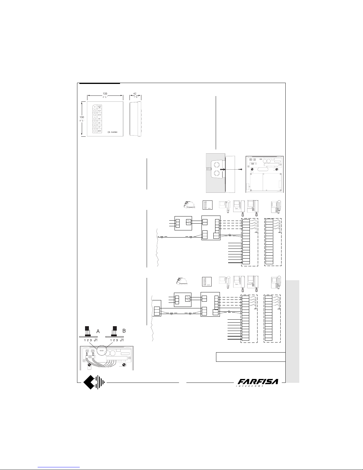
8-images video memory.
It records the image, hour and date of the last
8-persons which have made a call from the
video-intercom panel.
This video memory can be connected to any
video-intercom system.
Technical data
Power supply: 12Vac/dc
Current consumption: 0.4A
Video signal standard: CCIR
Recording delay after a call: 5 sec
Rec. inhibition after an image storing: 30sec
Memory capacity: 8 images
Hour, data mantaining in case of power failure:
30 min
+
IN
IN
P1
P2
P3
P4
8
1
3
1
10
4
9
11
12
13
14
2
12V
12V
127V
0
230V
AS
P
A
R
D
8
VM
OUT
OUT
T1
T2
T3
T4
8
1
3
1
10
4
9
11
12
13
14
2
VM08
To the timer and to the
video camera unit
+
IN
IN
P1
P2
P3
P4
8
1
3
1
10
4
9
11
12
13
14
2
12V
12V
127V
0
230V
AS
P
A
R
D
8
VM
T1
T2
T3
T4
8
1
3
1
10
4
9
11
12
13
14
2
VM08
PRS210
+
OUT
OUT
DV
OUT
OUT
Terminals
IN Video input 1Vpp composite into 75Ω
OUT Video output 1Vpp composite into 75Ω
12V Power supply 12V either ac or dc
8 12Vdc input (from the monitor)
+ 12Vdc output (to the video distributors)
3 Ground
D Supplementary input of the Del command
R Supplementary input of the Rec command
A Supplementary input of the Auto command
P Supplementary input of the Play command
PRS210
A position for one-way systems
B position for multi-way systems
IN OUT
12V 8 + 3 3 D R A P
1 2 3
Operating instructions.
It is advisable to install the video memory
close to the monitor, using the push-button
command on the video memory. If the recommended configuration is not achievable or in
the system there is more than one monitor it
would be possible to connect in parallel to the
main commands (DEL, REC, AUTO and
PLAY) located on the video memory using the
supplementary push-button on
the monitors. The video
memory should be powered
with 13V either ac or dc using
an external transformer or
power supply (e.g. PRS210).
IN OUT
12V 8 + 3 3 D R A P
1 2 3
For the functioning of video memory, see the
instruction manual provided with the product.
VC
VC
VC
VC
VIDEO MEMORY
Connection of the video memory in one-way systems.
INSTALLATION DIAGRAMS
To the riser of the videointercom system.
Connection of the video memory in multi-way systems.
In multi-way system, to avoid recording of
images directed to other monitors it is necessary to move the jumper J1 from position 1-
2 to position 2-3; it is also necessary to
connect coaxial cable and positive power
supply both of the video distributor and the
monitor as shown in the diagram the connections P, A, R and D drawn with dashed lines
on the diagram must be done only if additional commands are required on the monitor
(or if there is one or more monitors in parallel).
In one-way systems with one or more monitors in parallel, it is sufficient to connect the
coaxial cable from the video camera unit to
the terminal IN of the video memory the
terminal OUT should be connected to the
video input of the monitor.
The connections P, A, R and D drawn with
dashed lines on the diagram, must be done
only if additional commands are required on
the monitor or if there is one or more monitors
in parallel.
Page 26
26
WITHOUT
COAX *
WITH COAX
(GB- '99)
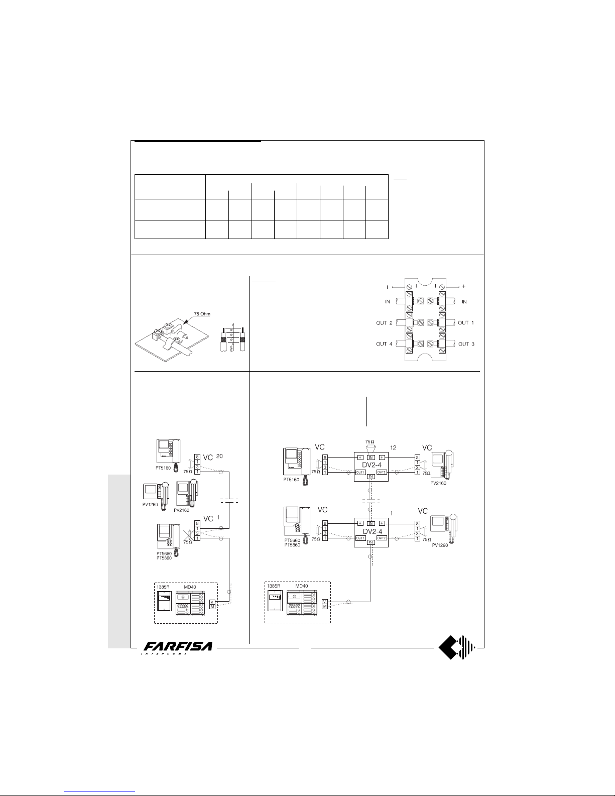
WIRE CROSS SECTION
VIDEO SIGNAL DISTRIBUTION
Serial connection of the coaxial cable (input and output from monitor)
To carry out the video connection in a serial
mode it is necessary to cut the resistance of
75Ω located on the wall-bracket terminal
board. Leave it only on the last monitor. The
monitors serially connectable are max. 20.
Connection of the coaxial cable with video floor distributors
For multi-way video systems it is advisable to
use floor video distributor that, being powered by the monitors connected to it (terminal
8), do not create overloads on the video
power supply. The outputs that are not used
must be closed with resistances of 75Ω that
are provided in kit. Maximum 12 video distributors can be connected together.
DV2-DV4. Video signal distributor.
They allow the distribution of the video signal
on 2 or 4 outputs. It can be installed on the
wall, on a wall box, with expansion plugs or it
can be placed in the junction box.
Technical data
Power supply 12Vdc±2
Operating current DV2 50mA
DV4 100mA
Insertion loss 0.8dB
Max. input video signal 2Vpp
Bandwidth >5MHz
Monitors terminal board
The resistance for closing of video signal
(75Ω) is located on the terminal board of the
monitor wall bracket.
* MODY *
ERREP/R
* PROJECT *
PUNTO
VIRGOLA * S
LIM
For the video signal use a 75Ω low loss coaxial cable.
INSTALLATION INSTRUCTIONS
660 Ft
AWG
16
16
terminal
art. 1382
4 - 9 - 11 - 12 - 13
H - 1 - 2 - 3 - F - D
10 (call)
F - 14 - A - S
(cables in bold face type)
distance
300m
S mm²
1.5
2.5
50m
S mm²
0.5
0.75
165 Ft
AWG
20
18
100m
S mm²
0.75
1
330 Ft
AWG
18
16
200m
S mm²
1
1.5
990 Ft
AWG
16
12
1304. Multipolar cable with 10
wires of different cross sections
and coaxial cable of 75Ω. It can be
used in systems with a maximum
distance of 100 meters (50m between timer and camera unit and
50m between timer and monitor).
Page 27
WITHOUT C
OAX *
WITH
COAX
27
(GB- '99)
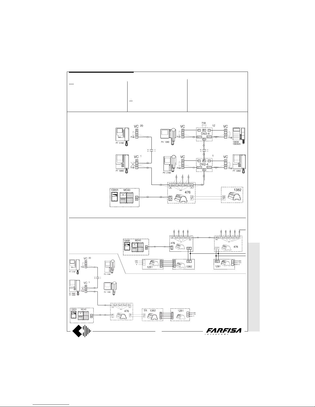
476. Video distributor-amplifier.
It allows for the distribution of the video signal
coming from the cameras on 5 independent
lines. It is not necessary to close on 75Ω the
unused outputs.
Connection of the coaxial cable with distribution on maximum 5 column rising (serial and/or with video floor distributors)
Connection of coaxial cable with distribution on 9 columns rising
In video systems with different
columns rising or with a high
number of users, it is necessary
to use the video distributor-amplifier art.476.
It is not necessary to close the
unused outputs on the 75Ω resistance.
If more than one video distributor is to be
used, an extra supply, art. 1281 is necessary.
Connection of art. 476 as video amplifier for long distance systems
For this use, one output is to be connected; do not close the other outputs on the 75Ω resistance.
* MODY * E
RREP/R *
PROJECT *
PUNTOVIRGOLA *
SLIM
Terminals
F General ground
14 Positive power supply
IN Video signal input
1-2-3-4-5 Video signal outputs
Video ground (shield of the coaxial cable)
Technical data
Power supply 21 ± 3Vdc
Operating current at max. load 250mA
Gain at max. load from 0 to 3.5dB (adjustable)
Gain with one output closed to 75Ω from 0 to 9dB
(adjustable)
Bandwidth >5MHz
Operating temperature 0°÷+50°C
Maximum permissible humidity 90% RH
Housing DIN 8 modules A
INSTALLATION INSTRUCTIONS
Page 28
28
WITHOUT
COAX *
WITH COAX
(GB- '99)
D
3
S
1
2
H
F
A
4
9
11
12
13
14
F
A
I
+
230V
0
127V
+
I
A
AL
VC
10
1
3
1
8
4
9
11
12
13
14
2
75Ω
IA+
0
127V
230V
4
9
11
12
13
14
F
A
I
+
+
I
A
0
127V
230V
AL
0
127V
230V
A + I
H
D
1
2
3
F
A
S
TR
1382
1281
AL
1281
1281
AL
1281
TR
1382
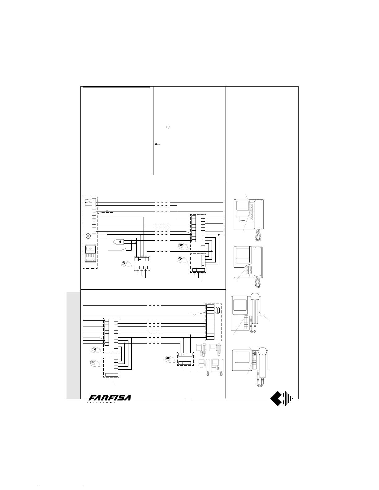
Check that the connections of the system are
carried out correctly.
Put the system in use by connecting the
power supply to the mains.
By pushing a call button from the external
push-button panel, it activates the bell of the
corresponding monitor and it activates the
system for a time of about 50 seconds. The
images appear on the monitor a few seconds
after the call.
Focus the scene to be filmed.
The user called, by lifting the handset, can
speak with the outside and at the same time
increase the activation time of the system
(about 3 minutes). If in the meantime another
call occurs, the monitor shuts itself off and
connects the last call. By replacing the handset the system shuts off automatically.
In case more calls occur simultaneously, a
protection circuit against overloading and
short circuiting is provided to disable the
timer and therefore to shut off the system.
In the absence of calls from the door station,
from any monitor (if provided in the system) it
is possible to control the entrance by pressing the
button (control switch ON). Such a
control is not possible with an active system
and when a conversation is taking place. To
work the electric door lock release press the
button from monitor series Project and
PV1260. For the FLAT PV2160 monitor press
the button to the right of the handset. In the
two or more entrance systems all the audio
and video communications and door lock
release, from one entrance to the other, are
automatically switched with the call or the
control switch ON.
In these systems the control switch ON from
the monitors can interrupt a running communication, for this reason it is advisable to
interrupt, by means of a relay 1471, all the
control switches ON when the video system is
active, giving the priority of the communication to the door stations (see page 24).
In systems with the intercommunicating service, the communication between monitors
and/or intercoms occur with system in standby.
Adjustments
All the regulations are carried out in the
factory. For possible corrections the intervention of a specialized technician is advisable. The Contrast and Brightness adjustments, being subject to the environmental
lighting conditions, are accessible from the
under neath by means of a screw driver.
Connection of an additional power supply in systems with long distance
between monitor and the power supply base
PT5160
PT5660
PT5860
PV2160
PV1260
V
M
H
1
2
3
4
PA
SE
Mody
UR
* MODY * E
RREP/R *
PROJECT *
PUNTOVIRGOLA *
SLIM
WORKING INSTRUCTIONS
Connection of an additional power supply in systems with long distance
between the camera unit and the power supply base
Function of monitor main buttons
"door lock release"
"control switch ON"
"control switch ON"
"door lock release"
"control
switch ON"
"door lock
release"
"door lock release"
"control switch ON"
Page 29
WITHOUT C
OAX *
WITH
COAX
29
(GB- '99)
* MODY * E
RREP/R *
PROJECT *
PUNTOVIRGOLA *
SLIM
The probability of breakdown in the videointercom systems is obviously greater than in
the intercom system. Consequently this brief
troubleshooting takes into consideration the
most common defects. When a defect is
limited to only one monitor it is evident that
the trouble is a short circuit to the monitor
itself, to the connecting terminal board or to
the wires that go to the riser. The simplest
way to test the efficiency of a monitor is to try
if in another flat where everything functions
correctly.
TROUBLESHOOTING
Preliminary checks
- Check for the presence of the mains voltage
between terminals 230 (or 127) and 0 of the
power supply.
- The power supply is not provided with fuses,
but all of its outputs are protected against
overloading and short circuiting by temperature sensors. To reset the power supply, power must be cut off for about one minute and
can be restored after having eliminated the
defect.
- Check the voltage output of the power
supply (see in detail the values indicated in
the power supply and control chapter).
- Check that the cross section of the wire
corresponds to what is indicated on page 26
and the descriptions of each diagram.
- Check that the connection of the wire corresponds to the installation diagram.
Intercommunicating systems
During the intercommunication the door
speaker is activated.
The video system is ON (privacy towards the
outside only when the video system is in
stand-by). The module for intercommunicating has not been plugged in the timer art.1443.
Defective timer.
No audio in the intercommunicating service.
The wall-brackets of the monitors have the J1
jumper in position of audio privacy (see pages
3, 5, 7, 9 and 10). Defective module for
intercommunicating. Defective timer.
The intercommunicating calls do not activate.
Check that the X1 and X2 wires are connected correctly. Check that the J1 jumper is
in intercommunication position see pages 3,
5, 7, 9 and 10).
System with more entrances
Entrance A is never activated.
Short circuit between 5 and 6 of the exchanger. Defective exchanger.
Entrance B is never activated.
Short circuit between 3 and 4 of the exchanger. Defective exchanger. Absence of
power supply on 1 and 2 of the exchanger
(12Vac).
Audio section
No audio from either channel.
Absence of power supply voltage between 3
and 4 of the electronic door speaker (6÷8Vdc).
Short circuit between 3 and F of the timer. The
11 wire is interrupted. Defective timer.
No audio from the monitors to the door
station.
The 12 or 1 wire (from the timer to the door
station) is interrupted or has a short circuit.
Absence of the ground connection to terminal
4 of the electric door speaker. Defective door
speaker.
No audio from the door station to the
monitors.
The 13 or 2 wire (from the timer to the door
station) is interrupted or has a short circuit.
Defective door speaker.
Audio with humming in the background
(50/60 Hz).
The wires have been canalized together with
cables that power AC high absorption loads.
Separate the ground connection of the electric door speaker and of the name plate lights.
As visualized in the installation diagrams the
name plate lights must be powered from
terminals A and F of the power supply-timer
or when there are more than 8 lights from a
supplementary transformer (PRS 210). Defective power supply.
At the door station a whistle is heard
(Larsen effect).
The electric door speaker is badly housed in
the push-button panel (the microphone must
be stuck to the panel). Lower the volume.
Radio reception on the door station.
The defect can occur when there is a transmitter working in the proximity. Apply a condenser from 0.1µF between terminals 1 and 3
of the electric door speaker.
Defects and probable trouble
Monitors shut OFF. Bells not functioning.
Control switching ON not functioning.
Absence of main voltage. Short circuits or
overloading of the output terminals of the
power supply and/or timer. Defective Power
supply. Defective timer.
Monitors shut OFF. Bells not functioning.
Control switch ON functioning.
The D wire is interrupted. Defective timer.
Monitors turn ON. Absence of image.
The H wire is interrupted. The coaxial cable is
interrupted or has a short circuit. The shield of
the coaxial cable is interrupted. The video
distributors (if present), are not being powered. Defective camera unit.
Control switch ON by monitors does not
function.
The 4 wire is interrupted. Defective timer.
The system does not shut OFF by replacing the handset.
Such a defect can also be due to the non
working audio system from the door station to
the monitors (see related chapter). Defective
timer. Defective electronic speaker.
Unfocused image.
Adjust correctly the lens of the camera. Defective camera.
Image only slightly contrasted and/or out
of synchronism.
Coaxial cable loss or bad quality.
Coaxial cable not of 75Ω. High distance system (use video amplifier art.476). Check the
correct connection of the coaxial cable (see
pages 26 and 27).
The electric door lock does not function.
Defective lock. The cross section of the wires
indicated in bold type is insufficient. A connecting wire to the lock has been interrupted.
The 9 wire is interrupted. Defective timer.
Page 30
WITHOUT C
OAX *
WITH
COAX
29
(GB- '99)
Page 31
WITHOUT
COAX *
WITH COAX
30
(GB- '99)
The following pages show the installation diagrams most often used in the video-intercom system. Upon request Farfisa supplies
installation diagrams for the configurations not present in this manual.
Multi-way systems with 1, 2 and 3 entrances
Combination intercom video-intercom systems
Multi-way systems with main entrance and auxiliary entrances
Intercommunicating multi-way systems with 1 or more entrances
One or two-way systems
One or two-way systems with intercommunicating service between monitor and intercom
For a clearer understanding of the diagrams, the sequence of terminals in each individual article has not been followed. Only the
terminal code is valid (letter e/o number) not the graphic sequence.
The items may have more terminals than the ones in the installation diagrams. The excess terminals must not be utilized.
The conduit of the wires of any video and video-intercom system must be carried out separately from the light or industrial system
as prescribed from the International standards.
It is advisable to provide behind the (fused spur) power supply a disconnecting and safety switch.
Before connecting the unit, make sure its data correspond to those of the mains.
The installation diagrams for 1 or more external stations illustrated in this technical manual have been represented with a one
monitor for each user. However , it is possible to “personalise” the installation by matching properly to the “base” diagrams of pages
31, 33, 37, 39, 41, 43, the applications of pages 50, 51, 52, 53, and 54. For further details, see page 48.
The installation diagrams from page 33 to page 47 use control panels of Mody or ErreP/R series (and camera unit 1385R), and
they can also be used for one-way installations and video kits of the Mody series. Connect one monitor, by using a one call wire,
and not the video distributor (the coaxial cable is connected directly to the monitor wall bracket).
Graphic designs
For a better comprehension of the installation diagrams we have made a list of the graphic symbols most often used.
Speaker
Microphone
Buzzer
Button
Additional electronic bell
Resistance
Lamp
Coaxial cable
Optional wire (usually control switching ON or intercommunicating calls)
N2
Nn
INST ALLATION DIAGRAMS
Dashed line (for schematic purposes the first and last monitors are designed in the multi-family systems. Theoretically
the needed monitors are inserted in such dashed lines to
complete the system)
Call wires (second and last)
Graphic overlap point to adjust the “application” diagram to
the “base” diagram (see page 48).
* MODY * E
RREP/R *
PROJECT *
PUNTOVIRGOLA *
SLIM
Page 32
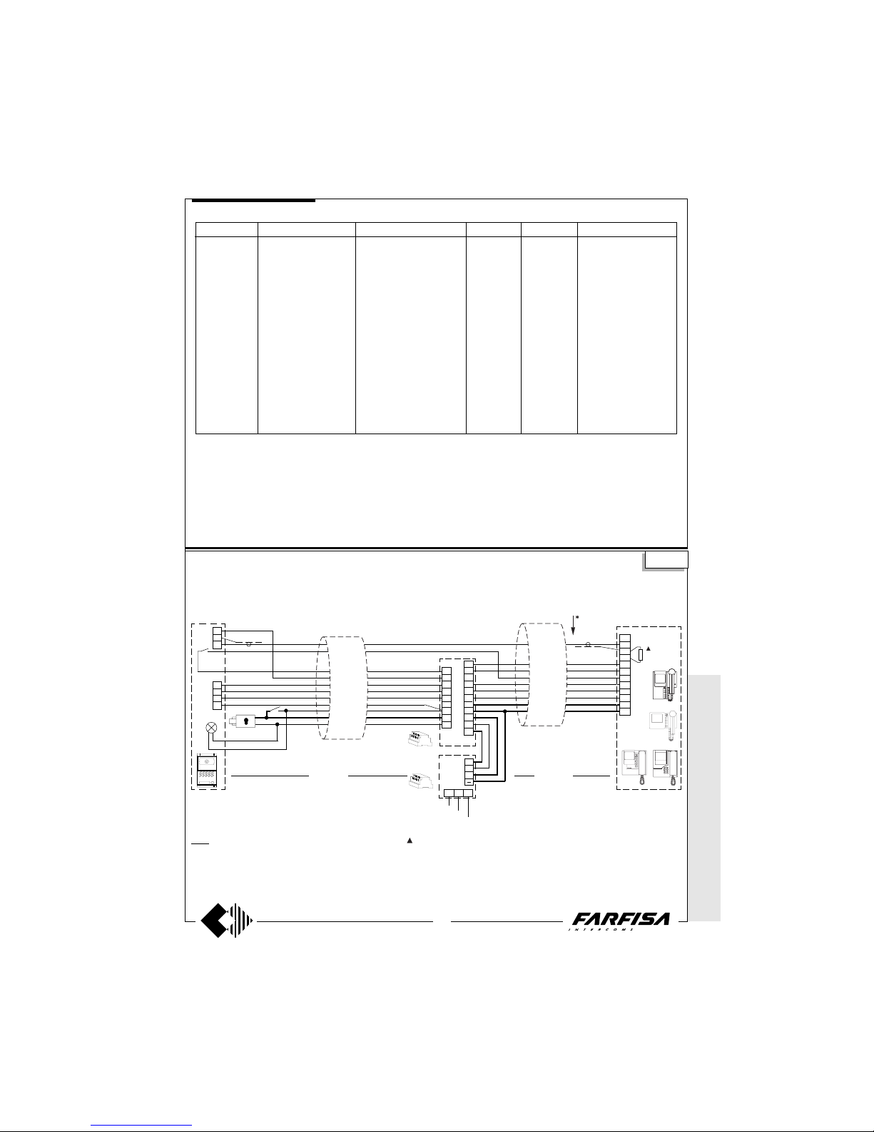
WITHOUT C
OAX *
WITH
COAX
31
(GB- '99)
MODY Videokit composition
Videokit Monitor + accessories External door station Power supply Timer Intercommunicating module
PT5100MD PT5160+WB5100 MD40+MD72+MD11+MD30 1281 1382 -
PT5100MDW PT5160W+WB5100 MD40+MD72+MD11+MD30 1281 1382 -
PT5160MD PT5160+WB5160 MD40+MD72+MD11+MD30 1281 1382 1443
PT5160MDW PT5160W+WB5160 MD40+MD72+MD11+MD30 1281 1382 1443
PT5600MDW PT5660W+WB5600+1283 MD40+MD72+MD11+MD30 1281 1382 -
PT5660MDW PT5660W+WB5660+1283 MD40+MD72+MD11+MD30 1281 1382 1443
PT5800MD PT5860+WB5600 MD40+MD72+MD11+MD30 1281 1382 -
PT5800MDW PT5860W+WB5600 MD40+MD72+MD11+MD30 1281 1382 -
PT5860MD PT5860+WB5660 MD40+MD72+MD11+MD30 1281 1382 1443
PT5860MDW PT5860W+WB5660 MD40+MD72+MD11+MD30 1281 1382 1443
PV1200MD PV1260+WB1200+1283 MD40+MD72+MD11+MD30 1281 1382 -
PV1260MD PV1260+WB1260+1283 MD40+MD72+MD11+MD30 1281 1382 1443
PV2100MD PV2160+WB2100 MD40+MD72+MD11+MD30 1281 1382 -
PV2160MD PV2160+WB2160 MD40+MD72+MD11+MD30 1281 1382 1443
ONE-WAY VIDEOKIT WITH APPLICATION OF THE MULTIPOLAR CABLE art.1304
D
H
1
2
3
F
S
A
8
1
3
1
4
9
10
11
12
13
14
2
+
I
A
0
127V
230V
AL
TR
Art. 1304
max 50m max 50m
1382
1281
VC
75Ω
4
9
11
12
13
14
F
A
I
+
H
M
V
1
2
3
4
SE
PA
MD30
MD11
MD40
MD72
coaxial
black
green
light blue
yellow
white
pink
blue
red
coaxial
light blue
black
green
white
pink
orange
grey
red
yellow
blue
Art. 1304
1304. Multipolar cable with 10 wires of different cross sections and coaxial cable of
75Ω. It can be used in systems with a maximum distance of 100 meters (50m between
timer and camera unit and 50m between timer
and monitor).
VC =PT5160 + WB5100
PT5660 + WB5600 + 1283
PT5860 + WB5600
PV2160 + WB2100
PV1260 + WB1200 + 1283
The 75Ω resistance inserted between
terminals 1 and 3 of monitors is supplied with
the product. It is not to be added.
As a service ACI Farfisa supplies one-way
systems in Video Kits, which include all the
necessary articles, except cables and electric door lock (see the table above).
The “base” installation diagram of video kits
is in this same page.
To increase the number of inputs, use the
installation diagrams on pages 37, 39, 41, 43,
and add the missing articles.
For one-way systems with several monitors
and/or parallel intercoms, with or without intercommunicating service, see the application diagrams (from page 50 to 53), add the
missing articles.
Read page 48 carefully, for the composition
of the diagram desired.
Si 5000M
* MODY * E
RREP/R *
PROJECT *
PUNTOVIRGOLA
* SLIM
Videokit series MODY
Graphic overlap point for extension of diagram (see page 48).
Page 33
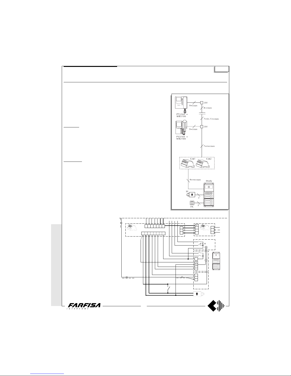
WITHOUT
COAX *
WITH COAX
32
(GB- '99)
VIDEO-INTERCOM SYSTEM WITH AUDIO-VIDEO PRIVACY
Diagram ref. Q.ty Article Description
VC ... PT 5160 + WB 5100 Monitor FLAT + wall bracket
PT 5660 + WB 5600 + 1283 Monitor + wall bracket + back box
PT 5860 + WB 5600 Monitor reflex + wall bracket
PV 1260 + WB1200 + 1283 Monitor + wall bracket + back box
PV 2160 + WB 2100 Monitor FLAT + wall bracket
DV ... DV2-4 Video floor distributors
AL 1 1281 Stabilized power supply
TR 1 1382 Audio-Video Timer
PA 1 ** Door release button
SE 1 ** Electric door lock (12Vac-1A)
External door station
Mody series (see pages 16, 17, 18, 19 for the composition)
1 row 2 row
UR 1 MD40 MD40 Camera module
PB ... MD72-73-74 MD72-73-74 Module frames and with back box
1 MD10-11-12 MD10-122-124 Modules for electric door speaker
... MD21 ÷ 24 MD222 ÷ 228 Button modules
... MD20 - 50 MD20 - 50 Blank and number modules
1 MD82 ÷ 812 MD82 ÷ 812 Hood covers
1 MD92 ÷ 912* MD92 ÷ 912* Rain shelters
PE 1 MD30 MD30 Electric door speaker
ErreP/R series (see pages 21, 22 for the composition)
UR 1 1385R Camera unit
PB 1 RP... Push-button panel
... R... Push-button panel
1 290R/2 ÷ 290R/38 Rain shelters
PE 1 337C Electric door speaker
... According to the number of users.
* The protective shelters are to be used instead
of back boxes and decorative shields.
** Articles not provided by ACI Farfisa.
Si 5050
Working instructions
See page 28.
Note
- The A and F terminals of article 1382 can be
connected to a maximum of 8 lamps (24V3W). If this number is exceeded, one or more
12V transformers and an proper power will be
required (type PRS210).
- If the control switch ON is needed connect
terminal 4 of the timer (dashed line).
- For the cross section of the wires see the
table on page 26.
- To connect the coaxial cable see pages 26
and 27.
For one-way systems or video kits of the
Mody series, connect the coaxial cable directly to the monitor wall bracket, without
using the DV floor video distributor (see diagram on page 31).
* MODY *
ERREP/R
* PROJECT *
PUNTO
VIRGOLA * S
LIM
One and multi-way systems
H
V
M
2
1
SE
4 9 11 12 13 14 F
230V
127V
FASH123D
Mody
PA
MD100
MD200
0
A
I
+
A
I
+
TR
1382
MD21
MD22
MD23
MD24
AL
1281
N1 N2 N3 Nn
C
MD40
MD72 - 73
Application of MD100 and MD200 modules in one and multiway systems
Page 34
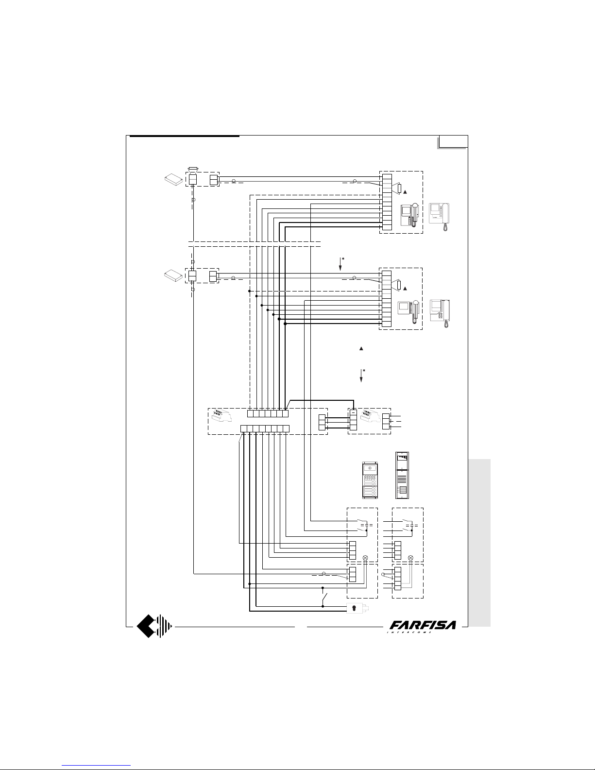
WITHOUT C
OAX *
WITH
COAX
33
(GB- '99)
VIDEO-INTERCOM SYSTEM WITH AUDIO-VIDEO PRIVACY
Si 5050
8
1
3
1
4
9
10
11
12
13
14
2
VC n
75Ω
H
V
M
4
3
2
1
PE
UR
H
V
M
A
F
4
3
2
1
PE
UR
PA
4 9 11 12 13 14 F
TR
AL
A
I
+
A
I
+
230V
127V
0
75 Ω
in
in
out
+
DV
SE
FASH123D
PB
PB
ErreP/R
Mody
in
in
DV
8
1
3
1
4
9
10
11
12
13
14
2
VC 1
75Ω
out
+
The 75Ω resistance inserted between
terminals 1 and 3 of monitors is supplied with
the product. It is not to be added.
Graphic overlap point for extension of
diagram (see page 48).
* M
ODY * ERRE
P/R * PROJECT *
PUNTO
VIRGOLA *
SLIM
One and multi-way systems
Page 35
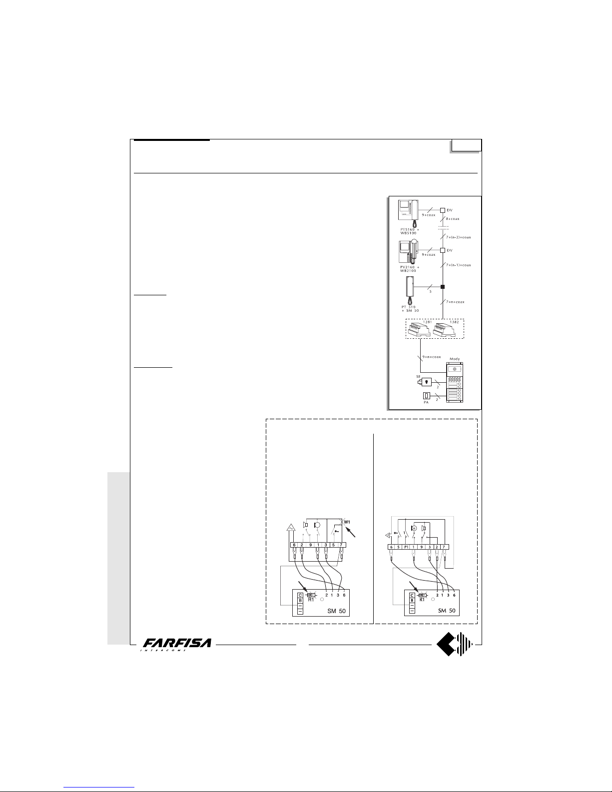
WITHOUT
COAX *
WITH COAX
34
(GB- '99)
MULTI-WAY COMBINED INTERCOM VIDEO-INTERCOM SYSTEM WITH AUDIO-VIDEO PRIVACY
Diagram ref. Q.ty Article Description
VC ... PT 5160 + WB 5100 Monitor FLAT + wall bracket
PT 5660 + WB 5600 + 1283 Monitor + wall bracket + back box
PT 5860 + WB 5600 Monitor reflex + wall bracket
PV 1260 + WB1200 + 1283 Monitor + wall bracket + back box
PV 2160 + WB 2100 Monitor FLAT + wall bracket
CT ... PT510 1 button intercom
PT520 2 button intercom
PV260 2 button intercom
SC ... SM50 Conversation privacy module
DV ... DV2-4 Video floor distributors
AL 1 1281 Stabilized power supply
TR 1 1382 Audio-Video Timer
PA 1 ** Door release button
SE 1 ** Electric door lock (12Vac-1A)
External door station
Mody series (see pages 16, 17, 18, 19 for the composition)
1 row 2 row
UR 1 MD40 MD40 Camera module
PB ... MD72-73-74 MD72-73-74 Module frames and with back box
1 MD10-11-12 MD10-122-124 Modules for electric door speaker
... MD21 ÷ 24 MD222 ÷ 228 Button modules
... MD20 - 50 MD20 - 50 Blank and number modules
1 MD82 ÷ 812 MD82 ÷ 812 Hood covers
1 MD92 ÷ 912* MD92 ÷ 912* Rain shelters
PE 1 MD30 MD30 Electric door speaker
ErreP/R series (see pages 21, 22 for the composition)
UR 1 1385R Camera unit
PB 1 RP... Push-button panel
... R... Push-button panel
1 290R/2 ÷ 290R/38 Rain shelters
PE 1 337C Electric door speaker
... According to the number of users.
* The protective shelters are to be used instead
of back boxes and decorative shields.
** Articles not provided by ACI Farfisa.
Si 5051
Working instructions
It is similar to the basic system described on
page 28, but with the following variations:
- from the intercom the user has about 40
seconds to answer by lifting the handset and
therefore can speak for an unlimited time with
video privacy towards the other users. By
replacing the handset the system shuts itself
OFF.
Note
- The A and F terminals of article 1382 can be
connected to a maximum of 8 lamps (24V-3W).
If this number is exceeded, one or more 12V
transformers and an proper power will be required (type PRS210).
- If the control switch ON is needed connect
terminal 4 of the timer (dashed line).
- If secrecy of conversation is not needed, all
the systems 4+1 Farfisa can be used.
- For the cross section of the wires see the
table on page 26.
- To connect the coaxial cable see pages 26
and 27.
Notes for systems of Project series:
- to cut the jumper W1 that links the
terminals 3 and 7.
- move the connection of the buzzer
from terminal 3 to 7.
- make the connection between terminal
7 of the intercom and the - (minus) of the
privacy module.
Cut the resistance R1 in all of the privacy modules.
Notes for systems of PV260, PV260W
intercoms:
- remove the jumper that links terminals 3 and 7.
- move the connection of the buzzer
from terminal 3 to 7.
- make the connection between terminal
7 of the intercom and the - (minus) of the
privacy module.
Cut the resistance R1 in all of the privacy modules.
Connection of secrecy module to the terminal board of the system
* MODY *
ERREP/R
* PROJECT *
PUNTO
VIRGOLA * S
LIM
Multi-way systems
Page 36
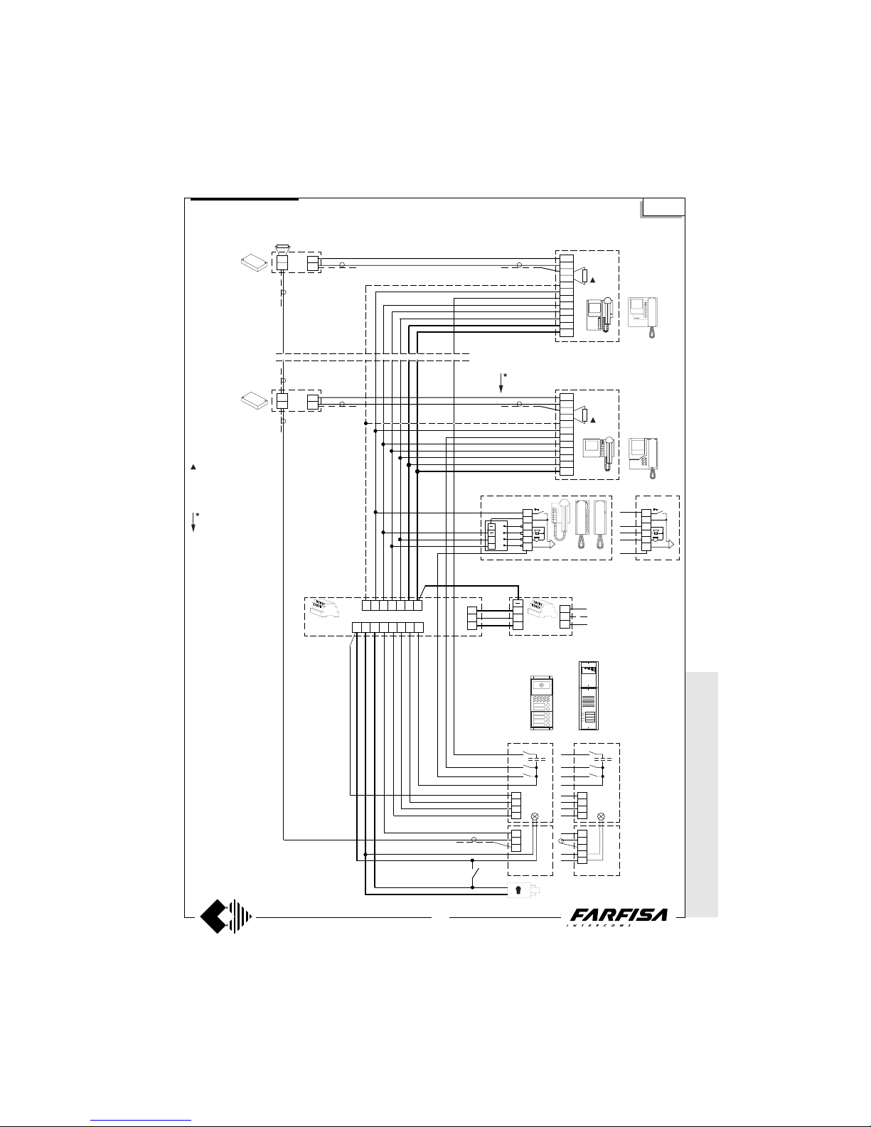
WITHOUT C
OAX *
WITH
COAX
35
(GB- '99)
MULTI-WAY COMBINED INTERCOM VIDEO-INTERCOM SYSTEM WITH AUDIO-VIDEO PRIVACY
Si 5051
8
1
3
1
4
9
10
11
12
13
14
2
VC n
75Ω
H
V
M
4
3
2
1
PE
UR
H
V
M
A
F
4
3
2
1
PE
UR
PA
4 9 11 12 13 14 F
TR
AL
230V
127V
0
75 Ω
in
in
out
+
DV
in
in
out
+
DV
8
1
3
1
4
9
10
11
12
13
14
2
VC 1
75Ω
SE
FASH123D
PB
PB
ErreP/R
Mody
5
7
3
2
1
6
CT
CT + SC
3
2
1
6
5
7
3
2
1
6
A
I
+
A
I
+
Graphic overlap point
for extension of diagram (see page 48).
The 75Ω resistance
inserted between terminals 1 and 3 of monitors
is supplied with the product. It is not to be added.
* MODY * E
RREP/R *
PROJECT *
PUNTOVIRGOLA *
SLIM
C
B
Intercom with audio privacy. Intercom without
audio privacy.
Multi-way systems
Page 37
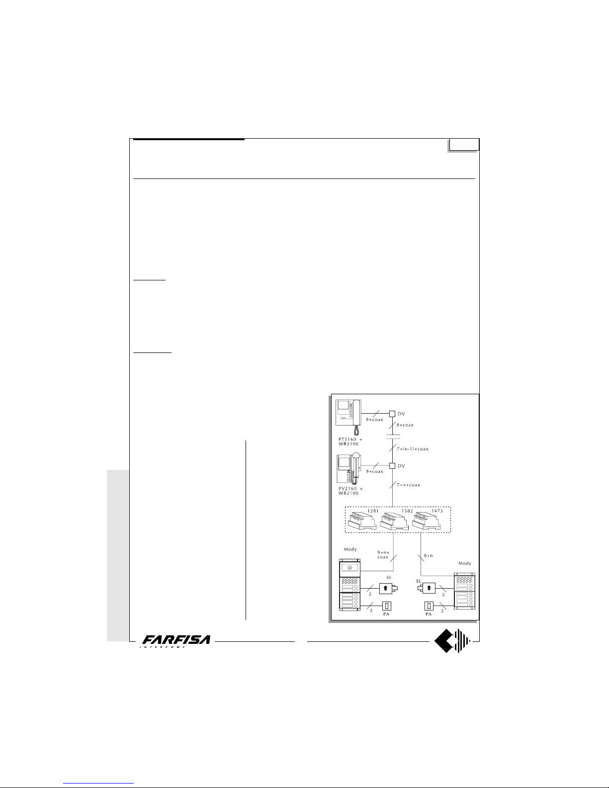
WITHOUT
COAX *
WITH COAX
36
(GB- '99)
VIDEO-INTERCOM SYSTEM WITH TWO AUTOMATICALLY SWITCHED ENTRANCES, ONE OF WHICH IS
ONLY AUDIO
Diagram ref. Q.ty Article Description
VC ... PT 5160 + WB 5100 Monitor FLAT + wall bracket
PT 5660 + WB 5600 + 1283 Monitor + wall bracket + back box
PT 5860 + WB 5600 Monitor reflex + wall bracket
PV 1260 + WB1200 + 1283 Monitor + wall bracket + back box
PV 2160 + WB 2100 Monitor FLAT + wall bracket
DV ... DV2-4 Video floor distributors
AL 1 1281 Stabilized power supply
TR 1 1382 Audio-Video Timer
DS 1 1473 Exchanger
PA 2 ** Door release button
SE 2 ** Electric door lock (12Vac-1A)
External door station
Mody series (see pages 16, 17, 18, 19 for the composition)
1 row 2 row
UR 1 MD40 MD40 Camera module
PB ... MD72-73-74 MD72-73-74 Module frames and with back box
2 MD10-11-12 MD10-122-124 Modules for electric door speaker
... MD21 ÷ 24 MD222 ÷ 228 Button modules
... MD20 - 50 MD20 - 50 Blank and number modules
2 MD82 ÷ 812 MD82 ÷ 812 Hood covers
2 MD92 ÷ 912* MD92 ÷ 912* Rain shelters
PE 2 MD30 MD30 Electric door speaker
ErreP/R series (see pages 21, 22 for the composition)
UR 1 1385R Camera unit
PB 2 RP... Push-button panel
... R... Push-button panel
2 290R/2 ÷ 290R/38 Rain shelters
PE 2 337C Electric door speaker
... According to the number of users.
* The protective shelters are to be used instead
of back boxes and decorative shields.
** Articles not provided by ACI Farfisa.
Si 5150
Note
- The A and F terminals of article 1382 can be
connected to a maximum of 6 lamps (24V3W). If this number is exceeded, one or more
12V transformers and an proper power will be
required (type PRS210).
- If the control switch ON is needed connect
terminal 4 of the timer (dashed line).
- In this system the control switch ON from the
monitors can interrupt a running communication, for this reason it is advisable to interrupt
it by means of a relay art.1471 (see page 24).
- For the cross section of the wires see the
table on page 26.
- To connect the coaxial cable see pages 26
and 27.
For one-way systems or video kits of the
Mody series, connect the coaxial cable directly to the monitor wall bracket, without
using the DV floor video distributor.
Working instructions
It is similar to the basic system
described on page 28, but with
the following variations:
- Carrying out a call from the
entrance only audio, the corresponding monitor turns itself
ON without images.
- The audio-video operations
and the door lock release are
automatically switched at the
time of the call or with the
control switch ON.
* MODY *
ERREP/R
* PROJECT *
PUNTO
VIRGOLA * S
LIM
One and multi-way systems
Page 38
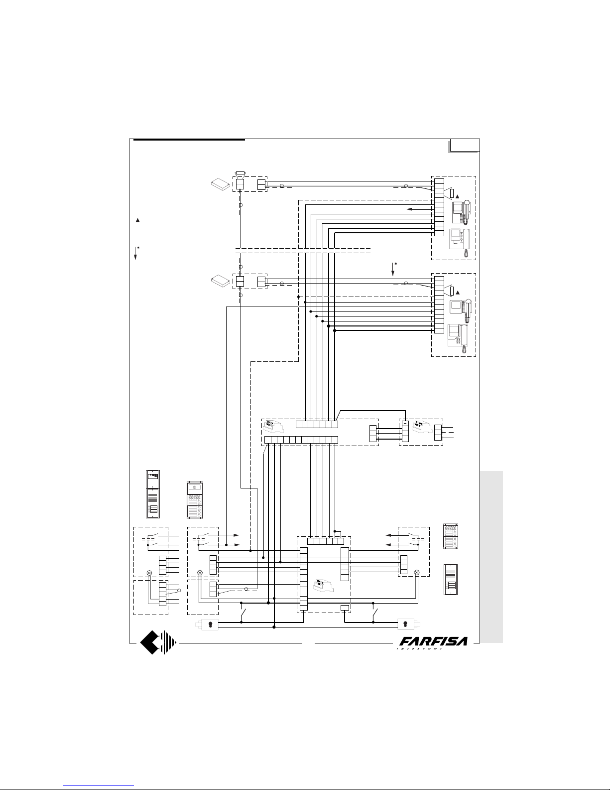
WITHOUT C
OAX *
WITH
COAX
37
(GB- '99)
4
10b
9b
8b
7b
VIDEO-INTERCOM SYSTEM WITH TWO AUTOMATICALLY SWITCHED ENTRANCES, ONE OF WHICH IS
ONLY AUDIO
8
1
3
1
4
9
10
11
12
13
14
2
VC n
75Ω
Si 5150
4
3
2
1
H
V
M
PE
UR
4
3
2
1
H
V
M
A
F
PE
UR
4
3
2
1
PE
" b "
Nn
N1
PAPA
N1
Nn
7891053
4 9 11 12 13 14 F
AL
230V
127V
0
75 Ω
in
in
out
+
DV
in
in
out
+
DV
8
1
3
1
4
9
10
11
12
13
14
2
VC 1
Nn
PB
PB
" a "" a "
PB
SE
SE
ErreP/R
Mody
6
10a
9a
8a
1
2
7a
DS
FA3 SH12D
TR
Mody
ErreP/R
A
I
+
A
I
+
75Ω
The 75Ω resistance inserted between terminals 1 and 3 of monitors is
supplied with the product. It is not to
be added.
Graphic overlap point for extension
of diagram (see page 48).
* MODY * E
RREP/R *
PROJECT *
PUNTOVIRGOLA
* SLIM
One and multi-way systems
Page 39
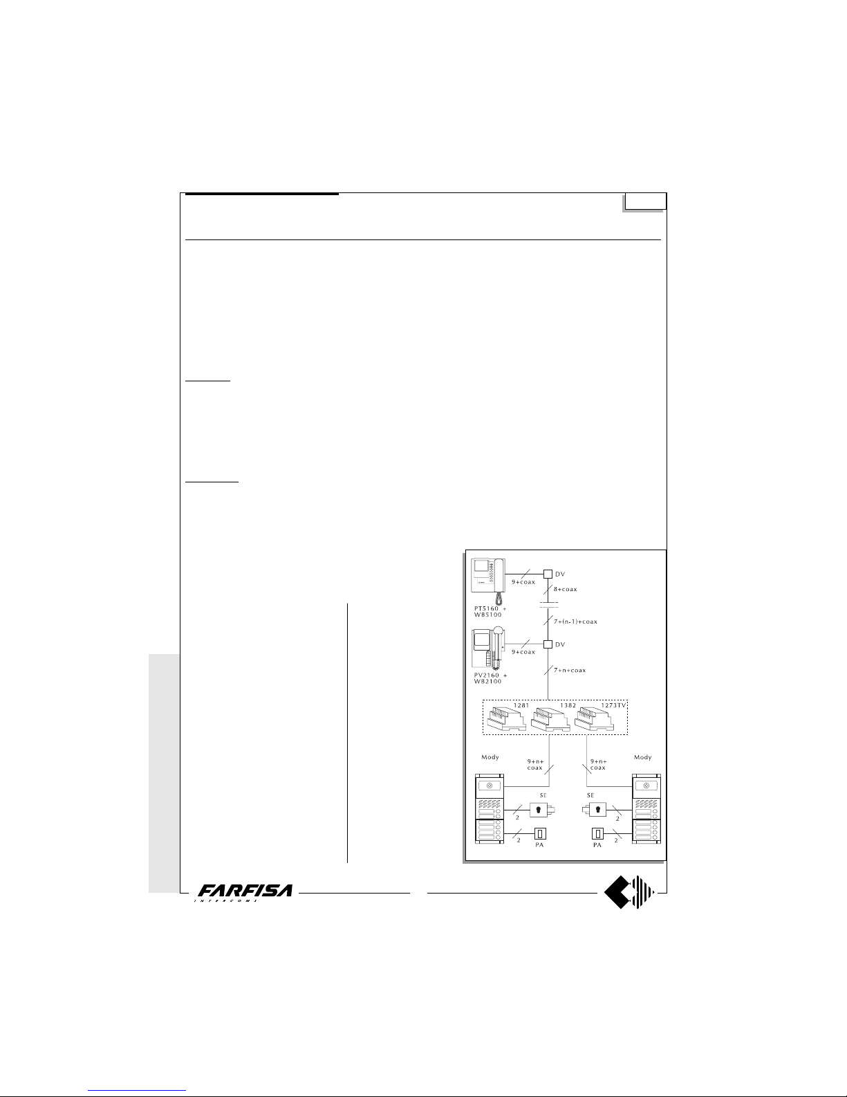
WITHOUT
COAX *
WITH COAX
38
(GB- '99)
VIDEO-INTERCOM SYSTEM WITH TWO AUTOMATICALLY SWITCHED VIDEO ENTRANCES
Diagram ref. Q.ty Article Description
VC ... PT 5160 + WB 5100 Monitor FLAT + wall bracket
PT 5660 + WB 5600 + 1283 Monitor + wall bracket + back box
PT 5860 + WB 5600 Monitor reflex + wall bracket
PV 1260 + WB1200 + 1283 Monitor + wall bracket + back box
PV 2160 + WB 2100 Monitor FLAT + wall bracket
DV ... DV2-4 Video floor distributors
AL 1 1281 Stabilized power supply
TR 1 1382 Audio-Video Timer
DS 1 1273TV Exchanger
PA 2 ** Door release button
SE 2 ** Electric door lock (12Vac-1A)
External door station
Mody series (see pages 16, 17, 18, 19 for the composition)
1 row 2 row
UR 2 MD40 MD40 Camera module
PB ... MD72-73-74 MD72-73-74 Module frames and with back box
2 MD10-11-12 MD10-122-124 Modules for electric door speaker
... MD21 ÷ 24 MD222 ÷ 228 Button modules
... MD20 - 50 MD20 - 50 Blank and number modules
2 MD82 ÷ 812 MD82 ÷ 812 Hood covers
2 MD92 ÷ 912* MD92 ÷ 912* Rain shelters
PE 2 MD30 MD30 Electric door speaker
ErreP/R series (see pages 21, 22 for the composition)
UR 2 1385R Camera unit
PB 2 RP... Push-button panel
... R... Push-button panel
2 290R/2 ÷ 290R/38 Rain shelters
PE 2 337C Electric door speaker
... According to the number of users.
* The protective shelters are to be used instead
of back boxes and decorative shields.
** Articles not provided by ACI Farfisa.
Si 5250
* MODY *
ERREP/R
* PROJECT *
PUNTO
VIRGOLA * S
LIM
One and multi-way systems
Note
- The A and F terminals of article 1382 can be
connected to a maximum of 6 lamps (24V-3W).
If this number is exceeded, one or more 12V
transformers and an proper power will be required (type PRS210).
- To have the control switch ON for the 2 video
entrances it is necessary to make the dashed
line connections and use WB5160, WB5660,
WB2160, WB1260 wall brackets.
- The wall brackets are configurated to work
without the audio privacy, to restore it the
jumper W1 must be moved (see pages 3, 5, 7,
9 and 10).
- In this system the control switch ON from the
monitors can interrupt a running communication, for this reason it is advisable to interrupt it
by means of a relay art.1471 (see page 24).
- For the cross section of the wires see the
table on page 26.
- To connect the coaxial cable see pages 26
and 27.
For one-way systems or video kits of the
Mody series, connect the coaxial cable directly to the monitor wall bracket, without using
the DV floor video distributor.
Working instructions
It is similar to the basic system
described on page 28, but with
the following variations:
- the audio-video operations
and the door lock release are
automatically switched at the
time of the call or with the control switch ON.
Page 40
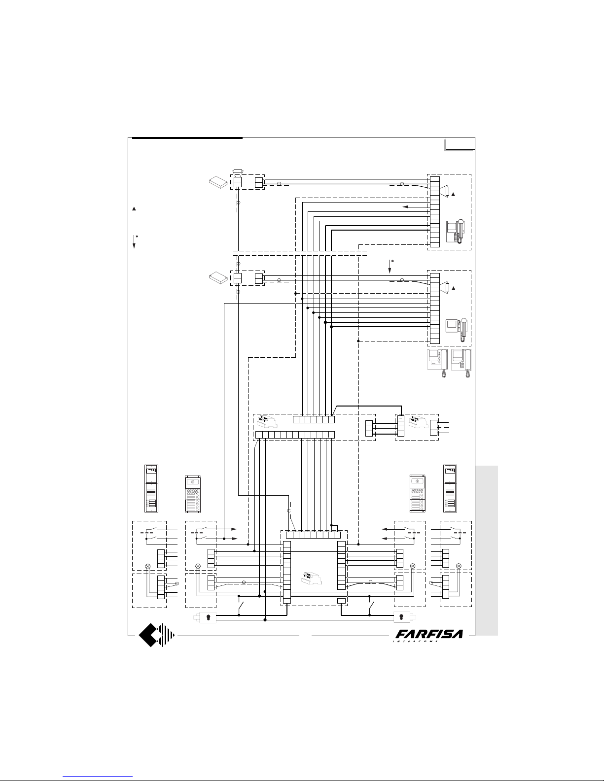
WITHOUT C
OAX *
WITH
COAX
39
(GB- '99)
4
13b
12b
11b
10b
9b
8b
7b
VIDEO-INTERCOM SYSTEM WITH TWO AUTOMATICALLY SWITCHED VIDEO ENTRANCES
8
1
3
1
4
9
10
11
12
13
14
2
X1
X2
T1
VC n
75Ω
Si 5250
4
3
2
1
H
V
M
PE
UR
4
3
2
1
H
V
M
A
F
PE
UR
H
V
M
4
3
2
1
PE
UR
" b "
Nn
N1
H
V
M
A
F
4
3
2
1
PE
UR
PAPA
N1
Nn
DS
6
13a
12a
11a
10a
9a
8a
1
2
7a
9871011121353
FA SH123D
4 9 11 12 13 14 F
TR
AL
230V
127V
0
75 Ω
in
in
out
+
DV
in
in
out
+
DV
8
1
3
1
4
9
10
11
12
13
14
2
X1
X2
P1
VC 1
Nn
PB
PB
" a "" a "
" b "
PB
PB
SE
SE
ErreP/R ErreP/R
Mody
Mody
A
I
+
A
I
+
75Ω
The 75Ω resistance inserted between
terminals 1 and 3 of monitors is supplied
with the product. It is not to be added.
Graphic overlap point for extension of
diagram (see page 48).
* MODY * E
RREP/R *
PROJECT *
PUNTOVIRGOLA
* SLIM
One and multi-way systems
Page 41
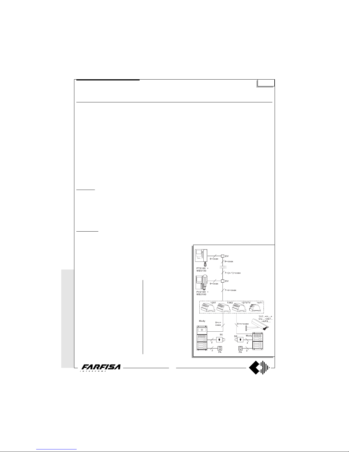
WITHOUT
COAX *
WITH COAX
40
(GB- '99)
Si 5256
VIDEO INTERCOM SYSTEM WITH TWO AUTOMATICALLY SWITCHED ENTRANCES, ONE WITH AN OUTDOOR
OR INDOOR SURVEILLANCE CAMERA
Diagram ref. Q.ty Article Description
VC ... PT 5160 + WB 5100 Monitor FLAT + wall bracket
PT 5660 + WB 5600 + 1283 Monitor + wall bracket + back box
PT 5860 + WB 5600 Monitor reflex + wall bracket
PV 1260 + WB1200 + 1283 Monitor + wall bracket + back box
PV 2160 + WB 2100 Monitor FLAT + wall bracket
DV ... DV2-4 Video floor distributors
AL 1 1281 Stabilized power supply
TR 1 1382 Audio-Video Timer
DS 1 1273TV Exchanger
IN 1 1471 Relay unit
PA 2 ** Door release button
SE 2 ** Electric door lock (12Vac-1A)
External door station
TE 1 TVT... Surveillance camera
1 H... Lens with or without auto-iris
1 CU... Climatized housing for outside
1 AST.. Jointed bracket for interior or housing
1 APS... Power supply for camera
LL 1 ** Lamp with maximum power of 800W
Mody series (see pages 16, 17, 18, 19 for the composition)
1 row 2 row
UR 1 MD40 MD40 Camera module
PB ... MD72-73-74 MD72-73-74 Module frames and with back box
2 MD10-11-12 MD10-122-124 Modules for electric door speaker
... MD21 ÷ 24 MD222 ÷ 228 Button modules
... MD20 - 50 MD20 - 50 Blank and number modules
2 MD82 ÷ 812 MD82 ÷ 812 Hood covers
2 MD92 ÷ 912* MD92 ÷ 912* Rain shelters
PE 2 MD30 MD30 Electric door speaker
ErreP/R series (see pages 21, 22 for the composition)
UR 1 1385R Camera unit
PB 2 RP... Push-button panel
... R... Push-button panel
2 290R/2 ÷ 290R/38 Rain shelters
PE 2 337C Electric door speaker
... According to the number of users.
* The protective shelters are to be used in-
stead of back boxes and decorative shields.
** Articles not provided by ACI Farfisa.
Note
- The A and F terminals of article 1382 can be
connected to a maximum of 6 lamps (24V-3W).
If this number is exceeded, one or more 12V
transformers and an proper power will be required (type PRS210).
- To have the control switch ON for the 2 video
entrances it is necessary to make the dashed
line connections and use WB5160, WB5660,
WB2160, WB1260 wall brackets.
- The wall brackets are configurated to work
without the audio privacy, to restore it the
jumper W1 must be moved (see pages 3, 5, 7,
9 and 10).
- In this system the control switch ON from the
monitors can interrupt a running communication, for this reason it is advisable to interrupt it
by means of a relay art.1471 (see page 24).
- For the cross section of the wires see the
table on page 26.
- To connect the coaxial cable see pages 26
and 27.
For one-way systems or video
kits of the Mody series, connect the coaxial cable directly
to the monitor wall bracket, without using the DV floor video
distributor.
Working instructions
It is similar to the basic system
described on page 28, but with
the following variations:
- the audio-video operations
and the door lock release are
automatically switched at the
time of the call or with the control switch ON.
- The surveillance camera remains in function in a timed
mode.
* MODY *
ERREP/R
* PROJECT *
PUNTO
VIRGOLA * S
LIM
One and multi-way systems
Page 42
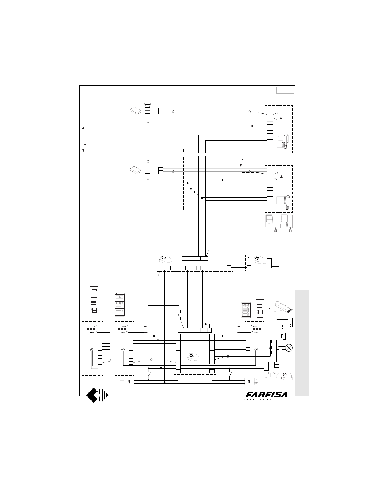
WITHOUT C
OAX *
WITH
COAX
41
(GB- '99)
VIDEO INTERCOM SYSTEM WITH TWO AUTOMATICALLY SWITCHED ENTRANCES, ONE WITH
AN OUTDOOR OR INDOOR SURVEILLANCE CAMERA
8
1
3
1
4
9
10
11
12
13
14
2
X1
X2
T1
VC n
75Ω
4
3
2
1
H
V
M
PE
UR
4
3
2
1
H
V
M
A
F
PE
UR
4
3
2
1
PE
Nn
N1
PAPA
N1
Nn
DS
6
13a
12a
11a
10a
9a
8a
1
2
7a
9871011121353
FA SH123D
4 9 11 12 13 14 F
TR
AL
230V
127V
0
75 Ω
in
in
out
+
DV
in
in
out
+
DV
8
1
3
1
4
9
10
11
12
13
14
2
X1
X2
P1
VC 1
Nn
PB
PB
" a "" a "
SE
ErreP/R
Mody
A
I
+
A
I
+
4
13b
12b
11b
9b
8b
10b
7b
2
3
5
6
TE
SE
IN
PB
Mody
ErreP/R
" b "
L
N
230V
230V
Si 5256
LL
75Ω
The 75Ω resistance inserted between
terminals 1 and 3 of monitors is supplied
with the product. It is not to be added.
Graphic overlap point for extension
of diagram (see page 48).
* MODY * E
RREP/R *
PROJECT *
PUNTOVIRGOLA
* SLIM
One and multi-way systems
Page 43
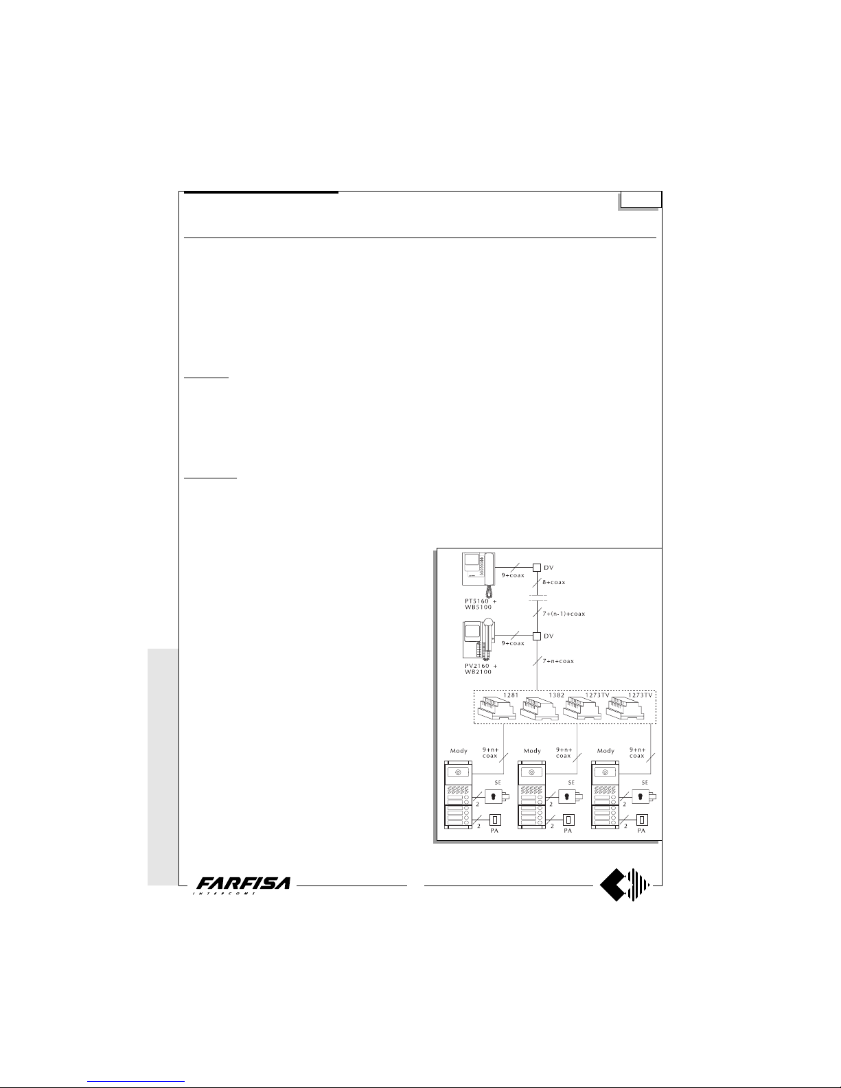
WITHOUT
COAX *
WITH COAX
42
(GB- '99)
Si 5350
* MODY *
ERREP/R
* PROJECT *
PUNTO
VIRGOLA *
SLIM
One and multi-way systems
VIDEO-INTERCOM SYSTEM WITH THREE AUTOMATICALLY SWITCHED VIDEO ENTRANCES
Diagram ref. Q.ty Article Description
VC ... PT 5160 + WB 5100 Monitor FLAT + wall bracket
PT 5660 + WB 5600 + 1283 Monitor + wall bracket + back box
PT 5860 + WB 5600 Monitor reflex + wall bracket
PV 1260 + WB1200 + 1283 Monitor + wall bracket + back box
PV 2160 + WB 2100 Monitor FLAT + wall bracket
DV ... DV2-4 Video floor distributors
AL 1 1281 Stabilized power supply
TR 1 1382 Audio-Video Timer
DS 2 1273TV Exchanger
PA 3 ** Door release button
SE 3 ** Electric door lock (12Vac-1A)
External door station
Mody series (see pages 16, 17, 18, 19 for the composition)
1 row 2 row
UR 3 MD40 MD40 Camera module
PB ... MD72-73-74 MD72-73-74 Module frames and with back box
3 MD10-11-12 MD10-122-124 Modules for electric door speaker
... MD21 ÷ 24 MD222 ÷ 228 Button modules
... MD20 - 50 MD20 - 50 Blank and number modules
3 MD82 ÷ 812 MD82 ÷ 812 Hood covers
3 MD92 ÷ 912* MD92 ÷ 912* Rain shelters
PE 3 MD30 MD30 Electric door speaker
ErreP/R series (see pages 21, 22 for the composition)
UR 3 1385R Camera unit
PB 3 RP... Push-button panel
... R... Push-button panel
3 290R/2 ÷ 290R/38 Rain shelters
PE 3 337C Electric door speaker
... According to the number of users.
* The protective shelters are to be used instead
of back boxes and decorative shields.
** Articles not provided by ACI Farfisa.
Note
- The A and F terminals of article 1382 can be connected to a
maximum of 5 lamps (24V-3W). If this number is exceeded, one or
more 12V transformers and an proper power will be required (type
PRS210).
- To have the control switch ON for the 3 video entrances it is
necessary to make the dashed line connections and use WB5160,
WB5660, WB2160, WB1260 wall brackets.
- The wall brackets are configurated to work without the audio
privacy, to restore it the jumper W1 must be moved (see pages 3,
5, 7, 9 and 10).
- In this system the control switch ON from the monitors can interrupt
a running communication, for this reason it is advisable to interrupt
it by means of a relay art.1471 (see page 24).
- For the cross section of the wires see the table on page 26.
- To connect the coaxial cable see pages 26 and 27.
For one-way systems or video kits of the Mody series, connect the
coaxial cable directly to the monitor wall bracket, without using the
DV floor video distributor.
Working instructions
It is similar to the basic system described on page 28, but with the
following variations:
- the audio-video operations and the door lock release are automatically switched at the time of the call or with the control switch ON.
Page 44
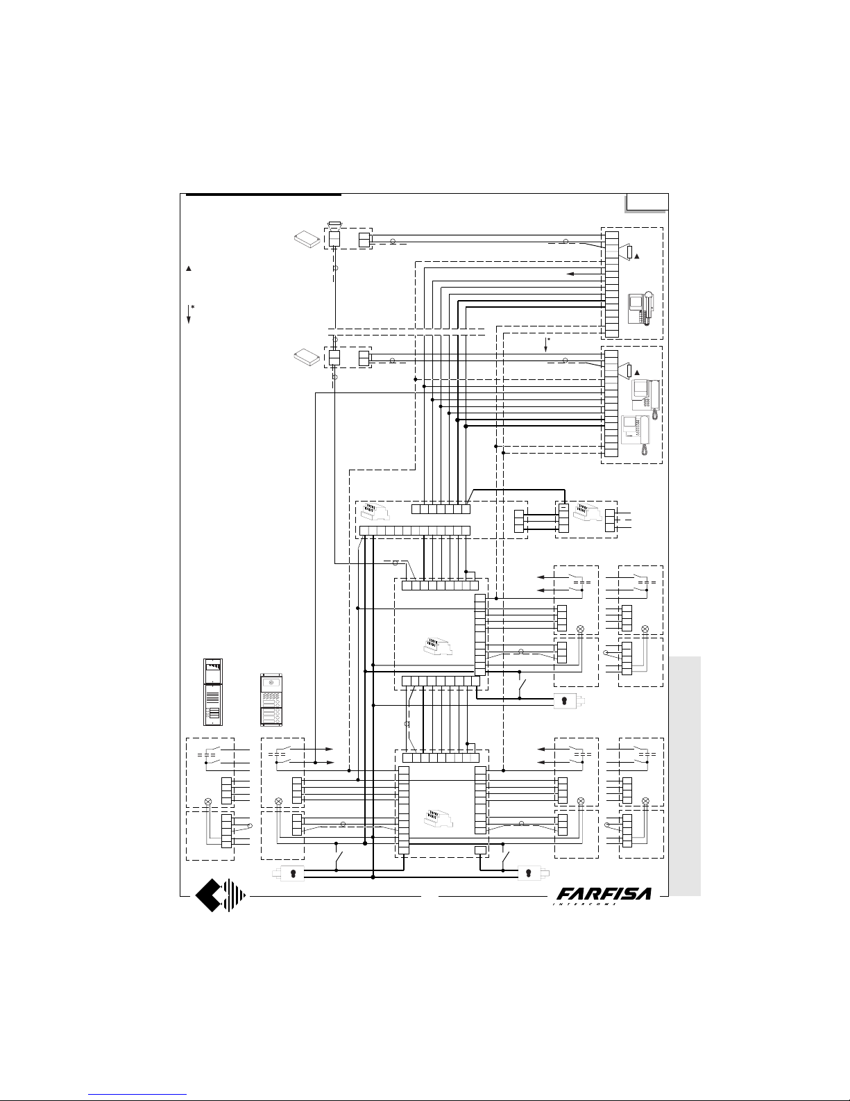
WITHOUT C
OAX *
WITH
COAX
43
(GB- '99)
9a 8a 7a 10a 11a 12a13a 6 7b
Si 5350
4
13b
12b
11b
10b
9b
8b
7b
4
3
2
1
H
V
M
PE
UR
4
3
2
1
H
V
M
A
F
PE
UR
H
V
M
4
3
2
1
PE
UR
" b "
Nn
N1
H
V
M
A
F
4
3
2
1
PE
UR
PA
N1
Nn
DS
6
13a
12a
11a
10a
9a
8a
1
2
7a
9871011121353
PB
PB
" a "" a "
PB
PB
SE
4
13b
12b
11b
10b
9b
8b
1
2
H
V
M
4
3
2
1
PE
UR
" c "
Nn
N1
H
V
M
A
F
4
3
2
1
PE
UR
PA
DS
9 8 7101112135 3
MD
MD
SE
FA SH123D
4 9 11 12 13 14 F
TR
AL
230V
127V
0
A
I
+
A
I
+
in
in
out
+
DV
8
1
3
1
4
9
10
11
12
13
14
2
X1
X2
P1
P2
VC 1
8
1
3
1
4
9
10
11
12
13
14
2
X1
X2
T1
T2
VC n
75Ω
75 Ω
in
in
out
+
DV
Nn
Mody
ErreP/R
PA
SE
Mody
ErreP/R
ErreP/R
Mody
The 75Ω resistance inserted between terminals 1 and 3 of monitors
is supplied with the product. It is not
to be added.
75Ω
VIDEO-INTERCOM SYSTEM WITH THREE AUTOMATICALLY SWITCHED VIDEO ENTRANCES
Graphic overlap point for extension
of diagram (see page 48).
* MODY * E
RREP/R *
PROJECT *
PUNTOVIRGOLA
* SLIM
One and multi-way systems
Page 45
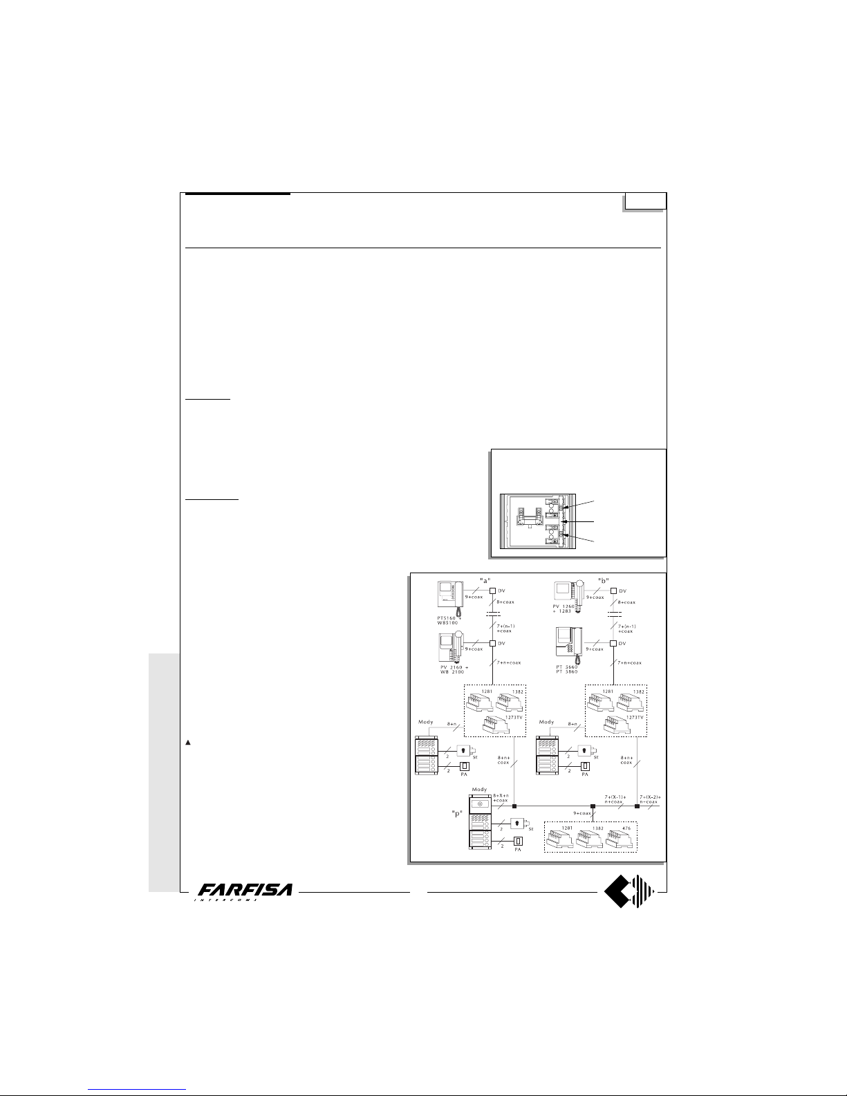
WITHOUT
COAX *
WITH COAX
44
(GB- '99)
MULTI-WAY VIDEO-INTERCOM SYSTEM WITH AUXILIARY AUDIO ENTRANCES AND ONE MAIN VIDEO
ENTRANCE ACCORDING TO THE STAIRWAY
Diagram ref. Q.ty Article Description
VC ... PT 5160 + WB 5100 Monitor FLAT + wall bracket
PT 5660 + WB 5600 + 1283 Monitor + wall bracket + back box
PT 5860 + WB 5600 Monitor reflex + wall bracket
PV 1260 + WB1200 + 1283 Monitor + wall bracket + back box
PV 2160 + WB 2100 Monitor FLAT + wall bracket
DV ... DV2-4 Video floor distributors
AV 1 476 Video distributor-amplifier
AL 1+X 1281 Stabilized power supply
TR 1+X 1382 Audio-Video Timer
DS X 1273TV Exchanger
PA 1+X ** Door release button
SE 1+X ** Electric door lock (12Vac-1A)
External door station
Mody series (see pages 16, 17, 18, 19 for the composition)
1 row 2 row
UR 1 MD40 MD40 Camera module
PB ... MD72-73-74 MD72-73-74 Module frames and with back box
1+X MD10-11-12 MD10-122-124 Modules for electric door speaker
... MD21 ÷ 24 MD222 ÷ 228 Button modules
... MD20 - 50 MD20 - 50 Blank and number modules
1+X MD82 ÷ 812 MD82 ÷ 812 Hood covers
1+X MD92 ÷ 912* MD92 ÷ 912* Rain shelters
PE 1+X MD30 MD30 Electric door speaker
ErreP/R series (see pages 21, 22 for the composition)
UR 1 1385R Camera unit
PB 1+X RP... Push-button panel
... R... Push-button panel
1+X 290R/2 ÷ 290R/38 Rain shelters
PE 1+X 337C Electric door speaker
... According to the number of users.
X According to the number of auxiliary entrances.
* The protective shelters are to be used instead
of back boxes and decorative shields.
** Articles not provided by ACI Farfisa.
Working instructions
It is similar to the basic system described on page 28, but with the
following variations:
- the audio-video operations and the door lock release are
automatically switched at the time of the call or with the control
switch ON.
- Carrying out a call from the entrance only audio, the corresponding monitor turns itself ON without images.
- The services towards the auxiliary audio entrances are independent among themselves and therefore they can function at
the same time.
Note
The 75Ω resistance inserted between terminals 1 and 3 of
monitors is supplied with the product. It is not to be added.
- The A and F terminals of article 1382 can be connected to a
maximum of 5 lamps (24V-3W). If this number is exceeded, one
or more 12V transformers and an proper power will be required
(type PRS210).
- In this system the control switch ON from the monitors can
interrupt a running communication, for this reason it is advisable
to interrupt it by means of a relay art.1471 (see page 24).
- For the cross section of the wires see the table on page 26.
- To connect the coaxial cable see pages 26 and 27.
common buttons 1
and 2
to separate buttons
common cut here
common buttons 3
and 4
The push-button panel of the main video entrance must have separate commons. A com-
mon for every auxiliary entrance. The buttons of
Mody series can be divided in groups of 2.
Si 5550
* MODY *
ERREP/R
* PROJECT *
PUNTO
VIRGOLA *
SLIM
Multi-way systems
Page 46
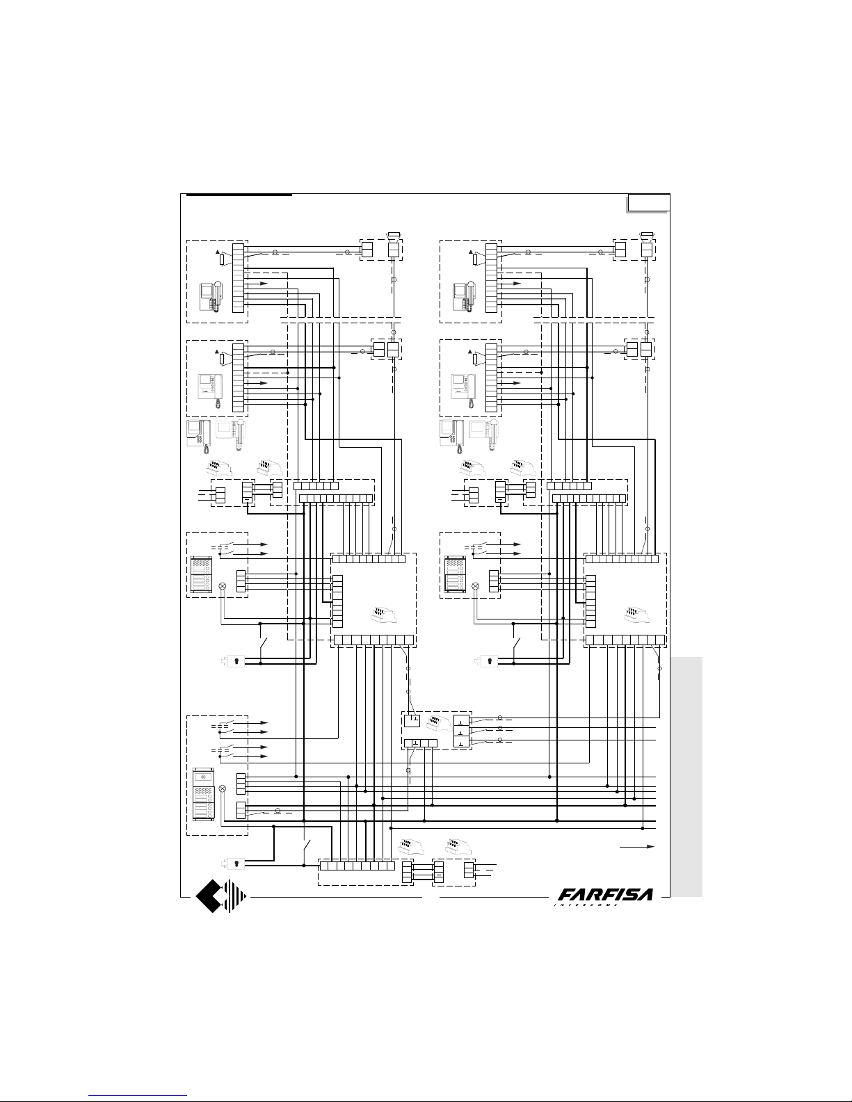
WITHOUT C
OAX *
WITH
COAX
45
(GB- '99)
MULTI-WAY VIDEO-INTERCOM SYSTEM WITH AUXILIARY AUDIO ENTRANCES AND ONE MAIN VIDEO
ENTRANCE ACCORDING TO THE STAIRWAY
* MODY * E
RREP/R *
PROJECT *
PUNTOVIRGOLA*
SLIM
Si 5550
Multi-way systems
1
OUT
47b1312113 78910
8
1
3
1
2
4
9
10
11
12
13
14
T1
VC n
75Ω
8
1
3
1
2
4
9
10
11
12
13
14
P1
75Ω
VC 1
A
I
+
11 14 13 12 4 F
FASH 9321D
TR
230V
0
127V
A
I
+
AL
4
3
2
1
( a )
SE
PE
4
3
2
1
SE
H
V
M
PE
( p )
+
in
in
75 Ω
out
+
DV
in
in
out
DV
PA
PA
SA3112FH9D
DS
TR
13b
12b
11b
10b
9b
8b
1
2
6 13a 12a 11a 10a 7a 5 8a 9a
OUT 2
OUT 3
OUT 4
IN F 14
AV
SE
PA
DS
13b
12b
11b
10b
9b
8b
1
2
6 13a 12a 11a 10a 7a 5 8a 9a
A
I
F
+
A
I
+
0
127V
230V
AL
" A "
Nn (a)
N1 (a)
Nn (a)
N1 (a)
Nn (b)
N1 (b)
" C ... "
N1 (a)
Nn (a)
UR
PB
4
3
2
1
PE
PB
47b1312113 78910
8
1
3
1
2
4
9
10
11
12
13
14
T1
VC n
75Ω
8
1
3
1
2
4
9
10
11
12
13
14
P1
75Ω
VC 1
A
I
+
11 14 13 12 4 F
FASH 9321D
TR
230V
0
127V
A
I
+
AL
( a )
+
in
in
75 Ω
out
+
DV
in
in
out
DV
" A "
Nn (a)
N1 (a)
N1 (a)
Nn (a)
PB
Page 47
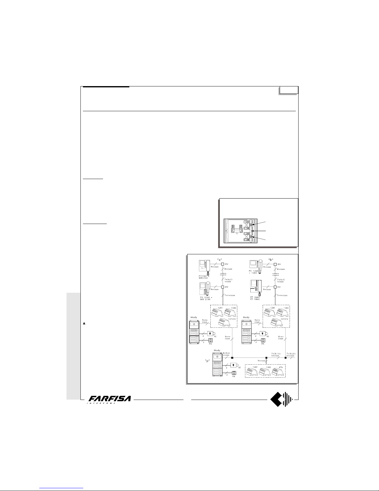
WITHOUT
COAX *
WITH COAX
46
(GB- '99)
MULTI-WAY VIDEO-INTERCOM SYSTEM WITH AUXILIARY VIDEO ENTRANCES AND ONE MAIN VIDEO
ENTRANCE ACCORDING TO THE STAIRWAY
Diagram ref. Q.ty Article Description
VC ... PT 5160 + WB 5100 Monitor FLAT + wall bracket
PT 5660 + WB 5600 + 1283 Monitor + wall bracket + back box
PT 5860 + WB 5600 Monitor reflex + wall bracket
PV 1260 + WB1200 + 1283 Monitor + wall bracket + back box
PV 2160 + WB 2100 Monitor FLAT + wall bracket
DV ... DV2-4 Video floor distributors
AV 1 476 Video distributor-amplifier
AL 1+X 1281 Stabilized power supply
TR 1+X 1382 Audio-Video Timer
DS X 1273TV Exchanger
PA 1+X ** Door release button
SE 1+X ** Electric door lock (12Vac-1A)
External door station
Mody series (see pages 16, 17, 18, 19 for the composition)
1 row 2 row
UR 1 +X MD40 MD40 Camera module
PB ... MD72-73-74 MD72-73-74 Module frames and with back box
1+X MD10-11-12 MD10-122-124 Modules for electric door speaker
... MD21 ÷ 24 MD222 ÷ 228 Button modules
... MD20 - 50 MD20 - 50 Blank and number modules
1+X MD82 ÷ 812 MD82 ÷ 812 Hood covers
1+X MD92 ÷ 912* MD92 ÷ 912* Rain shelters
PE 1+X MD30 MD30 Electric door speaker
ErreP/R series (see pages 21, 22 for the composition)
UR 1+X 1385R Camera unit
PB 1+X RP... Push-button panel
... R... Push-button panel
1+X 290R/2 ÷ 290R/38 Rain shelters
PE 1+X 337C Electric door speaker
... According to the number of users.
X According to the number of auxiliary entrances.
* The protective shelters are to be used instead
of back boxes and decorative shields.
** Articles not provided by ACI Farfisa.
Si 5551
common buttons 1
and 2
to separate buttons
common cut here
common buttons 3
and 4
The push-button panel of the main video entrance must have separate commons. A com-
mon for every auxiliary entrance. The buttons of
Mody series can be divided in groups of 2.
* MODY *
ERREP/R
* PROJECT *
PUNTO
VIRGOLA *
SLIM
Multi-way systems
Working instructions
It is similar to the basic system described on page 28, but with the
following variations:
- The audio-video operations and the door lock release are
automatically switched at the time of the call or with the control
switch ON.
- The services towards the auxiliary video entrances are independent among themselves and therefore they can function at the same
time.
Note
The 75Ω resistance inserted between terminals 1 and 3 of
monitors is supplied with the product. It is not to be added.
- The A and F terminals of article 1382 can be connected to a
maximum of 6 lamps (24V-3W). If this number is exceeded, one or
more 12V transformers and an proper power will be required (type
PRS210).
- To have the control switch ON for the 3 video entrances it is
necessary to make the dashed line connections and use WB5160,
WB5660, WB2160, WB1260 wall brackets.
- The wall brackets are configurated to work without the audio
privacy, to restore it the jumper W1 must be moved (see pages 3,
5, 7, 9 and 10).
- In this system the control switch ON from the monitors can
interrupt a running communication, for this reason it is advisable to
interrupt it by means of a relay art.1471 (see page 25).
- For the cross section of the wires see the table on page 26.
- To connect the coaxial cable see pages 26 and 27.
Page 48
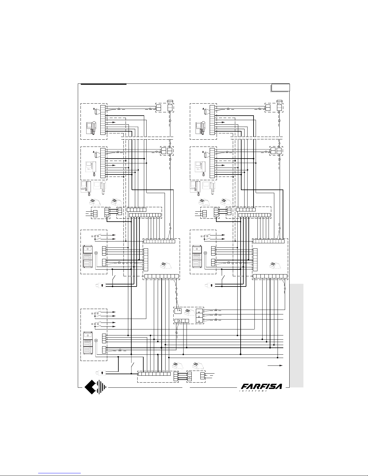
WITHOUT C
OAX *
WITH
COAX
47
(GB- '99)
MULTI-WAY VIDEO-INTERCOM SYSTEM WITH AUXILIARY VIDEO ENTRANCES AND ONE MAIN VIDEO
ENTRANCE ACCORDING TO THE STAIRWAY
Si 5551
* MODY * E
RREP/R *
PROJECT *
PUNTOVIRGOLA
* SLIM
Multi-way systems
1
OUT
4
3
2
1
SE
H
V
M
PE
4
3
2
1
SE
H
V
M
PE
( p )
PA
PA
SA3112FH9D
DS
TR
13b
12b
11b
10b
9b
8b
1
2
6 13a 12a 11a 10a 7a 5 8a 9a
OUT 2
OUT 3
OUT 4
IN F 14
AV
SE
PA
DS
13b
12b
11b
10b
9b
8b
1
2
6 13a 12a 11a 10a 7a 5 8a 9a
A
I
F
+
A
I
+
0
127V
230V
AL
Nn (a)
N1 (a)
Nn (b)
N1 (b)
" C ... "
UR
PB
UR
4
3
2
1
H
V
M
PE
UR
47b1312113 78910
8
1
3
1
2
4
9
10
11
12
13
14
T1
VC n
75Ω
8
1
3
1
2
4
9
10
11
12
13
14
P1
75Ω
VC 1
A
I
+
11 14 13 12 4 F
FASH 9321D
TR
230V
0
127V
A
I
+
AL
( a )
+
in
in
75 Ω
out
+
DV
in
in
out
DV
" A "
Nn (a)
N1 (a)
N1 (a)
Nn (a)
PB
47b1312113 78910
8
1
3
1
2
4
9
10
11
12
13
14
T1
VC n
75Ω
8
1
3
1
2
4
9
10
11
12
13
14
P1
75Ω
VC 1
A
I
+
11 14 13 12 4 F
FASH 9321D
TR
230V
0
127V
A
I
+
AL
( a )
+
in
in
75 Ω
out
+
DV
in
in
out
DV
" A "
Nn (a)
N1 (a)
N1 (a)
Nn (a)
PB
Page 49
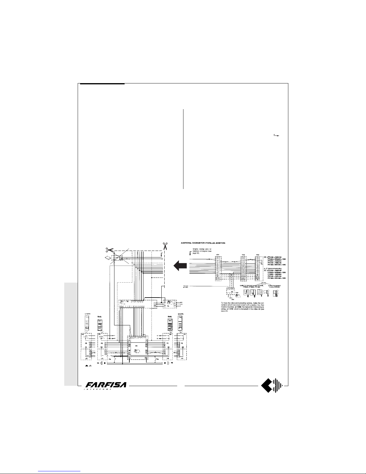
WITHOUT
COAX *
WITH COAX
48
(GB- '99)
All installation diagrams in this technical manual we have used only
one monitor for each user. It is possible to “personalise” the installation, by matching properly to the “base” diagrams of pages 31, 33, 35,
37, 39, 41, 43, the applications on the following pages (50 to 54). Such
examples refer to applications with a one video-intercom entrance. To
plan systems with 2 or more audio-video entrances, and if more than
one control switch-ON is needed, use the first buttons of monitor (P1,
P2 or T1, T2, etc.), by making the terminals for intercommunicating
calls slide on to the lower ones (P3, P4 or T3, T4).
In the “base” diagrams the dashed lines identify the wires for control
switch-ON, whereas in the “additional” diagrams the dashed lines
refer to the wires for intercommunicating service.
When the simultaneous switch-ON of several monitors is needed,
and extra power supplies are to be added, take care that terminal I of
timer 1382 can be connected to a maximum of 3 power supplies
1281.
EXTENSION OF VIDEO INTERCOM SYSTEM
Extension of a ONE-WAY system
To plan a one-way system with several monitors and/or parallel
intercoms and with or without intercommunicating service, pro-
ceed as follows.
- make a photocopy of the “additional” diagram desired, selecting it
between those of pages 50, 51, 52, 53;
- cut vertically the diagram in correspondence to the arrow
;
- put the diagram on the “base” diagram, so as to cover the existing
monitor, then line up the wires of the 2 diagrams;
- if specified in the “additional” diagram, connect the I and A wires to
the terminals of article 1382;
- to obtain the intercommunicating service, make the connections
which have been drawn with a dashed line.
Example: by making a photocopy of the “additional” diagram of page
50 (3 parallel monitors), then applying it on to the installation diagram
of page 39 (Si 5250), and lining it up to the riser wires, it is possible
to obtain a one-way system, with 3 parallel monitors connected to 2
external video stations.
* MODY *
ERREP/R
* PROJECT *
PUNTO
VIRGOLA * S
LIM
Working diagrams
To P3 terminal
Page 50
WITHOUT C
OAX *
WITH
COAX
49
(GB- '99)
Extension in a one apartment of a MULTI-WAY system
To plan a multi-way system with several monitors and/or parallel
intercoms in a one apartment, with or without intercommunicating
service, proceed as follows:
- make a photocopy of the “additional” diagram desired, selecting it
amongst those of pages 50, 51, 52, 53;
- cut vertically the diagram in correspondence to the arrow
;
- put the diagram on the “base” diagram, so as to cover the existing
monitor, then line up the wires of the 2 diagrams;
- if specified in the “additional” diagram, connect the I and A wires to
the terminals of article 1382;
- if the “base” diagram includes the DV video distributor, remember to
connect the terminal + to the terminal 8 of all monitors;
Note. if the intercommunicating service between monitors or systems
is also needed, once the system is on, the user can listen to other
users, who are speaking to the outside.
If such an option is not desired, use the diagrams of page 54 to make
the extension (see the following chapter).
Example: by making a photocopy of the “additional” diagram of page
52 (1 monitor and 2 parallel intercoms), then applying it on to the
installation diagram of page 43 (Si 5350), and lining it up to the riser
wires, it is possible to obtain a multi-way system, with 1 monitor and
2 parallel intercoms in one apartment, connected to 3 external video
stations.
Extension of a MULTI-WAY installation in several apartments
To plan a multi-way system, with several monitors and/or parallel
intercoms, in 2 or more apartments, with or without intercommuni-
cating service, proceed as follows:
- make a photocopy of the “additional” diagram desired, selecting it
amongst those of page 54;
- cut vertically the diagram in correspondence to the arrow
;
- put the diagram on the “base” diagram, so as to cover the existing
monitor, then line up the wires of the 2 diagrams;
- repeat the operations for the application in other apartments;
- if the “base” diagram includes the DV video distributor, remember to
connect the terminal + to the terminal 8 of all monitors;
- to obtain the intercommunicating service, make the connections
which have been drawn with a dashed line.
Example: by making a photocopy of the “additional” diagram of page
54 (1 monitor and 2 parallel intercoms), then applying it on to the
installation diagram of page 43 (Si 5350), and lining it up to the riser
wires, it is possible to obtain a multiway system in one or more
apartments, with 1 monitor and 2 parallel intercoms, connected to 3
external video stations.
EXTENSION OF VIDEO INTERCOM SYSTEM
Working diagrams
* MODY * E
RREP/R *
PROJECT *
PUNTOVIRGOLA *
SLIM
Page 51
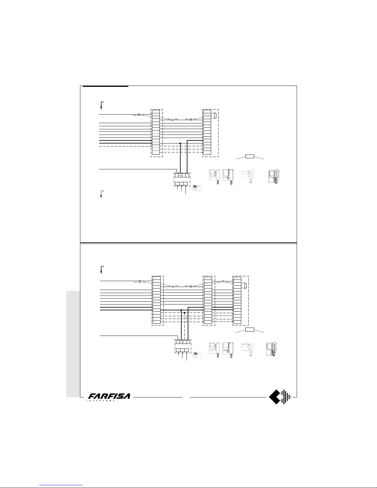
WITHOUT
COAX *
WITH COAX
50
(GB- '99)
8
1
3
1
4
9
10
11
12
13
14
2
X1
X2
P1-T1
VC1
IA+
AL
0
127V
230V
VC2
8
1
3
1
4
9
10
11
12
13
14
2
X1
P1-T1
X2
ADDITIONAL DIAGRAM FOR 2 PARALLEL MONITORS
P1-T1
VC =PT5160 + WB5100
PT5660 + WB5600 + 1283
PT5860 + WB5600
PV2160 + WB2100
PV1260 + WB1200 + 1283
or, if intercommunicating
VC =PT5160 + WB5160
PT5660 + WB5660 + 1283
PT5860 + WB5660
PV2160 + WB2160
PV1260 + WB1260 + 1283
To have the intercommunicating service, make the connections which have been drawn with a dashed line, then
insert in the timer, art.1382, the module for intercommunicating, art.1443, which is included in the video kit (see
page 23).
1281
75Ω
IA+
AL
0
127V
230V
VC2
8
1
3
1
4
9
10
11
12
13
14
2
X1
P1-T1
X2
P2-T2
8
1
3
1
4
9
10
11
12
13
14
2
X1
P1-T1
P2-T2
X2
VC3
8
1
3
1
4
9
10
11
12
13
14
2
X1
X2
P1-T1
P2-T2
VC1
P1-T1
1281
VC =PT5160 + WB5100
PT5660 + WB5600 + 1283
PT5860 + WB5600
PV2160 + WB2100
PV1260 + WB1200 + 1283
or, if intercommunicating
VC =PT5160 + WB5160
PT5660 + WB5660 + 1283
PT5860 + WB5660
PV2160 + WB2160
PV1260 + WB1260 + 1283
75Ω
ADDITIONAL DIAGRAM FOR 3 PARALLEL MONITORS
Terminal I
(art.1382)
Terminal A
(art.1382)
Terminal I
(art.1382)
Graphic overlap point for
extension of diagram (see
page 48).
Graphic overlap point for
extension of diagram (see
page 48).
Working diagrams
* MODY *
ERREP/R
* PROJECT *
PUNTO
VIRGOLA * S
LIM
symbol for terminal
monitor PV2160
symbol for terminal monitor PT5160,
PT5660, PT5860, PV1260
symbol for terminal
monitor PV2160
symbol for terminal monitor PT5160,
PT5660, PT5860, PV1260
To have the intercommunicating service, make the connections which have been drawn with a dashed line, then
insert in the timer, art.1382, the module for intercommunicating, art.1443, which is included in the video kit (see
page 23).
Page 52
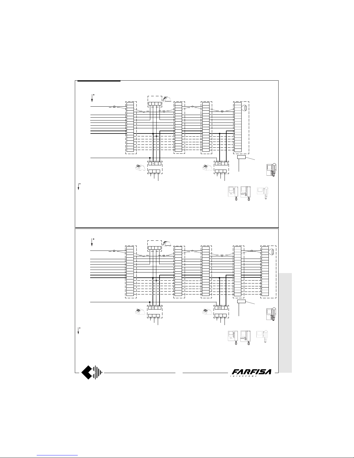
WITHOUT C
OAX *
WITH
COAX
51
(GB- '99)
symbol for terminal
monitor PT5160,
PT5660, PT5860,
PV1260
Working diagrams
* MODY * E
RREP/R *
PROJECT *
PUNTOVIRGOLA
* SLIM
1356
IN
IA+
AL
0
127V
230V
IA+
AL
0
127V
230V
VC4
8
1
3
1
4
9
10
11
12
13
14
2
X1
P1-T1
P2-T2
P3-T3
X2
P4-T4
8
1
3
1
4
9
10
11
12
13
14
2
X1
X2
P1-T1
P2-T2
P3-T3
P4-T4
VC1
Terminal I
(art.1382)
1471 VC2
8
1
3
1
4
9
10
11
12
13
14
2
X1
P1-T1
X2
P2-T2
P3-T3
P4-T4
8
1
3
1
4
9
10
11
12
13
14
2
X1
P1-T1
P2-T2
X2
P3-T3
P4-T4
VC3
VC =
PT5160 + WB5100
PT5660 + WB5600 + 1283
PT5860 + WB5600
PV2160 + WB2100
PV1260 + WB1200 + 1283
or, if intercommunicating
PT5160 + WB5160
PT5660 + WB5660 + 1283
PT5860 + WB5660
PV2160 + WB2160
PV1260 + WB1260 + 1283
1281
1281
75Ω
P1-T1
To have the intercommunicating service, make the connections which have been drawn with a dashed line, then
insert in the timer, art.1382, the module for intercommunicating, art.1443, which is included in the video kit (see
page 23).
ADDITIONAL DIAGRAM FOR 4 PARALLEL MONITORS
Graphic overlap point for
extension of diagram (see
page 48).
symbol for terminal
monitor PV2160
symbol for terminal
monitor PT5160,
PT5660, PT5860,
PV1260
1356
IN
IA+
AL
0
127V
230V
IA+
AL
0
127V
230V
VC4
8
1
3
1
4
9
10
11
12
13
14
2
X1
P1-T1
P2-T2
P3-T3
X2
P4-T4
8
1
3
1
4
9
10
11
12
13
14
2
X1
X2
P1-T1
P2-T2
P3-T3
P4-T4
VC1
Terminal I
(art.1382)
1471 VC2
8
1
3
1
4
9
10
11
12
13
14
2
X1
P1-T1
X2
P2-T2
P3-T3
P4-T4
8
1
3
1
4
9
10
11
12
13
14
2
X1
P1-T1
P2-T2
X2
P3-T3
P4-T4
VC3
VC =
PT5160 + WB5100
PT5660 + WB5600 + 1283
PT5860 + WB5600
PV2160 + WB2100
PV1260 + WB1200 + 1283
or, if intercommunicating
PT5160 + WB5160
PT5660 + WB5660 + 1283
PT5860 + WB5660
PV2160 + WB2160
PV1260 + WB1260 + 1283
1281
1281
8
1
3
1
4
9
10
11
12
13
14
2
X1
P1-T1
P2-T2
P3-T3
P4-T4
X2
VC5
75Ω
P1-T1
To have the intercommunicating service, make the connections which have been drawn with a dashed line, then
insert in the timer, art.1382, the module for intercommunicating, art.1443, which is included in the video kit (see
page 23).
ADDITIONAL DIAGRAM FOR 5 PARALLEL MONITORS
Graphic overlap point for
extension of diagram (see
page 48).
symbol for terminal
monitor PV2160
Page 53
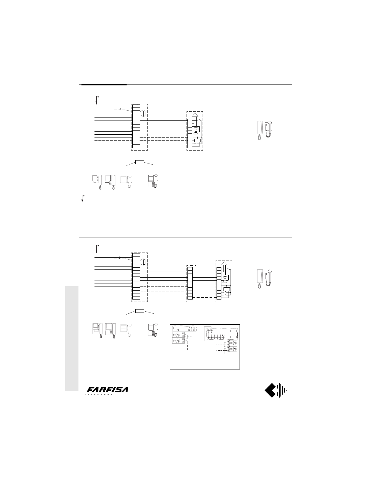
WITHOUT
COAX *
WITH COAX
52
(GB- '99)
symbol for terminal
monitor PV2160
symbol for terminal
monitor PT5160,
PT5660, PT5860,
PV1260
Working diagrams
* MODY *
ERREP/R
* PROJECT *
PUNTO
VIRGOLA *
SLIM
8
1
3
1
4
9
10
11
12
13
14
2
X1
X2
P1-T1
VC
Terminal A
(art.1382)
75Ω CT1
ADDITIONAL DIAGRAM FOR 1 MONITOR AND 1 INTERCOM
5
6
3
1
2
7
X1
P1
X2
SR40
P1-T1
To have the intercommunicating service, make the connections which have been drawn with a dashed line, then
insert in the timer, art.1382, the module for intercommunicating, art.1443, which is included in the video kit (see
page 23).
In all intercoms take out the mobile jumper which links the
terminals 3 and 7 (or cut the W1 jumper in the Project
models). Then apply the electronic bell SR40, and the
button groups.
VC =
PT5160 + WB5100
PT5660 + WB5600 + 1283
PT5860 + WB5600
PV2160 + WB2100
PV1260 + WB1200 + 1283
or, if intercommunicating
PT5160 + WB5160
PT5660 + WB5660 + 1283
PT5860 + WB5660
PV2160 + WB2160
PV1260 + WB1260 + 1283
CT =
PT510
PV100
924
or, if intercommunicating
PT520 + SR40 + PT501
PV260 + SR40 + SP10
symbol for terminal
monitor PV2160
symbol for terminal
monitor PT5160,
PT5660, PT5860,
PV1260
5
6
3
1
2
7
X1
P1
X2
P2
8
1
3
1
4
9
10
11
12
13
14
2
X1
X2
P1-T1
P2-T2
VC
Terminal A
(art.1382)
75Ω CT2
CT1
ADDITIONAL DIAGRAM FOR 1 MONITOR AND 2 PARALLEL INTERCOMS
5
6
3
1
2
7
X1
P1
P2
X2
SR40
P1-T1
To have the intercommunicating service, make the connections which have been drawn with a dashed line, then
insert in the timer, art.1382, the module for intercommunicating, art.1443, which is included in the video kit (see
page 23).
In all intercoms take out the mobile jumper which links the
terminals 3 and 7 (or cut the W1 jumper in the Project
models). Then apply the electronic bell SR40, and the
button groups.
VC =
PT5160 + WB5100
PT5660 + WB5600 + 1283
PT5860 + WB5600
PV2160 + WB2100
PV1260 + WB1200 + 1283
or, if intercommunicating
PT5160 + WB5160
PT5660 + WB5660 + 1283
PT5860 + WB5660
PV2160 + WB2160
PV1260 + WB1260 + 1283
CT =
PT510
PV100
924
or, if intercommunicating
PT520 + SR40 + PT501
PV260 + SR40 + SP10
Note
In all the intercommunicating intercoms, connect one of the two terminals of the single
button group to terminal 7.
PT520PV260
Graphic overlap point for
extension of diagram (see
page 48).
Page 54
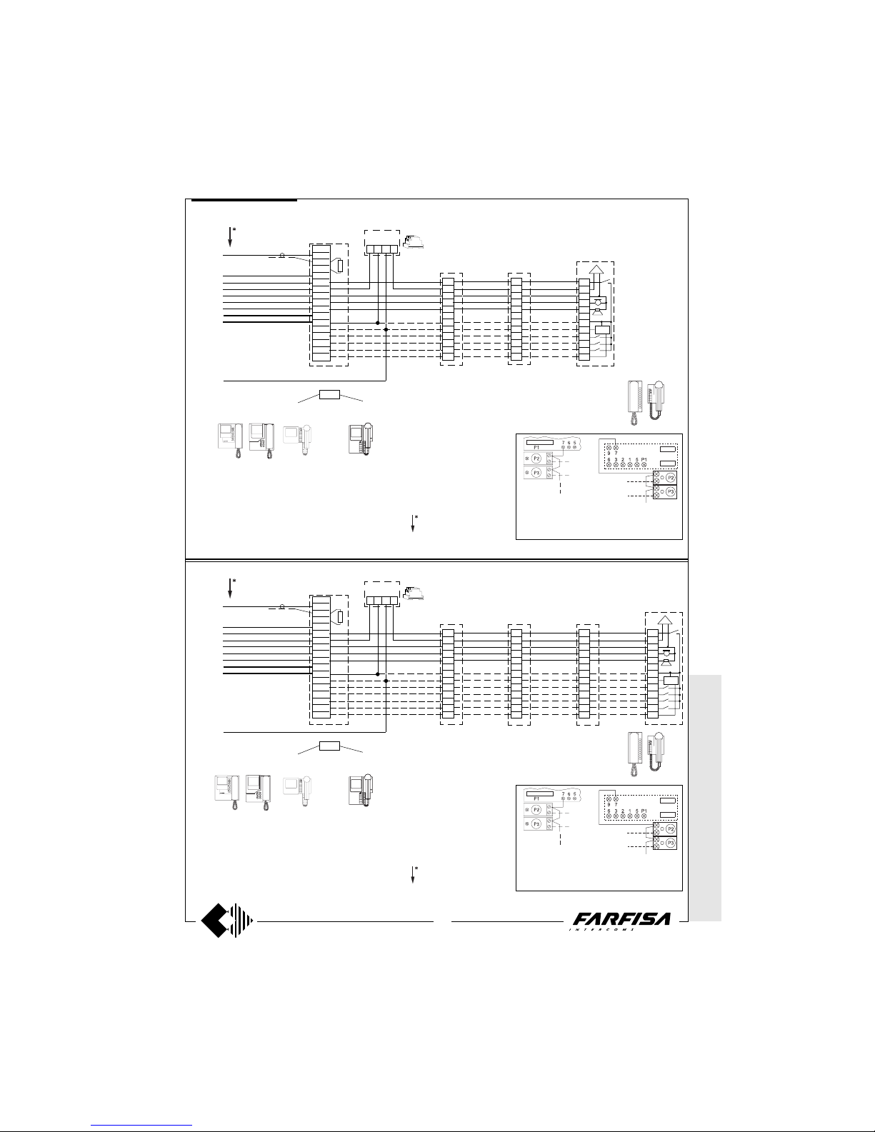
WITHOUT C
OAX *
WITH
COAX
53
(GB- '99)
1356
IN
5
6
3
1
2
7
X1
P1
P2
X2
P3
P4
5
6
3
1
2
7
X1
P1
P2
P3
P4
X2
SR40
5
6
3
1
2
7
X1
P1
P2
P3
X2
P4
5
6
3
1
2
7
X1
P1
X2
P2
P3
P4
8
1
3
1
4
9
10
11
12
13
14
2
X1
X2
P1-T1
P2-T2
P3-T3
P4-T4
VC
75Ω
P1-T1
CT4
CT2 CT3CT1
1471
To have the intercommunicating service, make the connections which have been drawn with a dashed line, then
insert in the timer, art.1382, the module for intercommunicating, art.1443, which is included in the video kit (see
page 23).
In all intercoms take out the mobile jumper which links the
terminals 3 and 7 (or cut the W1 jumper in the Project
models). Then apply the electronic bell SR40, and the
button groups.
Terminal A
(art.1382)
ADDITIONAL DIAGRAM FOR 1 MONITOR AND 4 PARALLEL INTERCOMS
VC =
PT5160 + WB5100
PT5660 + WB5600 + 1283
PT5860 + WB5600
PV2160 + WB2100
PV1260 + WB1200 + 1283
or, if intercommunicating
PT5160 + WB5160
PT5660 + WB5660 + 1283
PT5860 + WB5660
PV2160 + WB2160
PV1260 + WB1260 + 1283
CT =PT510; PV100; 924
or, if intercommunicating
PT520 + SR40 + PT501
PV260 + SR40 + SP10
Graphic overlap point for
extension of diagram (see
page 48).
Note
In all the intercommunicating intercoms, connect one of the two terminals of the single
button group to terminal 7.
PT520PV260
symbol for terminal
monitor PV2160
symbol for terminal
monitor PT5160,
PT5660, PT5860,
PV1260
1356
IN
5
6
3
1
2
7
X1
P1
P2
X2
P3
5
6
3
1
2
7
X1
P1
X2
P2
P3
8
1
3
1
4
9
10
11
12
13
14
2
X1
X2
P1-T1
P2-T2
P3-T3
VC
75Ω
P1-T1
CT2 CT3CT1
1471
To have the intercommunicating service, make the connections which have been drawn with a dashed line, then
insert in the timer, art.1382, the module for intercommunicating, art.1443, which is included in the video kit (see
page 23).
In all intercoms take out the mobile jumper which links the
terminals 3 and 7 (or cut the W1 jumper in the Project
models). Then apply the electronic bell SR40, and the
button groups.
Terminal A
(art.1382)
ADDITIONAL DIAGRAM FOR 1 MONITOR AND 3 PARALLEL INTERCOMS
VC =
PT5160 + WB5100
PT5660 + WB5600 + 1283
PT5860 + WB5600
PV2160 + WB2100
PV1260 + WB1200 + 1283
or, if intercommunicating
PT5160 + WB5160
PT5660 + WB5660 + 1283
PT5860 + WB5660
PV2160 + WB2160
PV1260 + WB1260 + 1283
CT =PT510; PV100; 924
or, if intercommunicating
PT520 + SR40 + PT501
PV260 + SR40 + SP10
Graphic overlap point for
extension of diagram (see
page 48).
Note
In all the intercommunicating intercoms, connect one of the two terminals of the single
button group to terminal 7.
PT520PV260
symbol for terminal
monitor PV2160
symbol for terminal
monitor PT5160,
PT5660, PT5860,
PV1260
5
6
3
1
2
7
X1
P1
P2
P3
X2
SR40
* MODY *
ERREP/R
* PROJECT *
PUNTOVIRGOLA
* SLIM
Working diagrams
Page 55
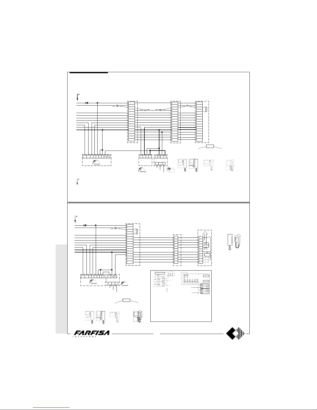
WITHOUT
COAX *
WITH COAX
54
(GB- '99)
symbol for terminal
monitor PV2160
* MODY *
ERREP/R
* PROJECT *
PUNTO
VIRGOLA * S
LIM
Working diagrams
ADDITIONAL DIAGRAM FOR MULTI-WAY SYSTEMS WITH 3 INTERCOMMUNICATING PARALLEL MONITORS
ADDITIONAL DIAGRAM FOR MULTI-WAY SYSTEMS WITH 1 MONITOR AND 2 PARALLEL INTERCOMS
P1-T1
VC =
PT5160 + WB5100
PT5660 + WB5600 + 1283
PT5860 + WB5600
PV2160 + WB2100
PV1260 + WB1200 + 1283
or, if intercommunicating
PT5160 + WB5160
PT5660 + WB5660 + 1283
PT5860 + WB5660
PV2160 + WB2160
PV1260 + WB1260 + 1283
Graphic overlap point for
extension of diagram (see
page 48).
Note
In all the intercommunicating intercoms, connect one of the two terminals of the single
button group to terminal 7.
In all intercoms take out the mobile jumper
which links the terminals 3 and 7 (or cut the W1
jumper in the Project models). Then apply the
electronic bell SR40, and the button groups.
PT520PV260
symbol for terminal
monitor PT5160,
PT5660, PT5860,
PV1260
5
6
3
1
2
7
X1
P1
X2
P2
75Ω CT2
CT1
5
6
3
1
2
7
X1
P1
P2
X2
SR40
8
1
3
1
4
9
10
11
12
13
14
2
X1
X2
P1-T1
P2-T2
VC
(Diode 100V-1A / type 1N4002)
230V
AL
0
127V
+
13a 12a 12 13 14 O F B
2443
SA
PRS220
CT =
PT510
PV100
924
or, if intercommunicating
PT520 + SR40 + PT501
PV260 + SR40 + SP10
VC2
8
1
3
1
4
9
10
11
12
13
14
2
X1
P1-T1
X2
P2-T2
8
1
3
1
4
9
10
11
12
13
14
2
X1
P1-T1
P2-T2
X2
VC3
8
1
3
1
4
9
10
11
12
13
14
2
X1
X2
P1-T1
P2-T2
VC1
P1-T1
VC =PT5160 + WB5100
PT5660 + WB5600 + 1283
PT5860 + WB5600
PV2160 + WB2100
PV1260 + WB1200 + 1283
or, if intercommunicating
VC =PT5160 + WB5160
PT5660 + WB5660 + 1283
PT5860 + WB5660
PV2160 + WB2160
PV1260 + WB1260 + 1283
75Ω
13a 12a 12 13 14 O F
2443
SA
IA+
AL
0
127V
230V
2536
IN
1471
(Diode 100V-1A / type 1N4002)
1281
symbol for terminal monitor PT5160,
PT5660, PT5860, PV1260
symbol for terminal monitor
PV2160
Page 56
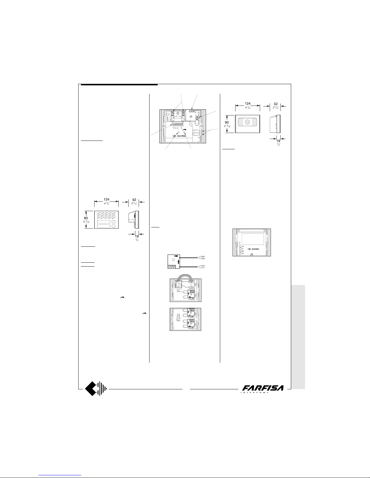
WITHOUT
COAX *
WITH COAX
55
(GB- '99)
The products of this line allow for the realization of a system with 4 common wires for all
monitors, and one for each user, without
using the coaxial cable.
It is possible to receive a call from any monitor, from the external station, it is possible to
see, communicate with the caller and release
the electric door lock.
PUSH-BUTTON PANELS
Mody series .
To plan a 4+1 video intercom system all the
button modules can be used, as well as the
back boxes, the protective shelters and the
decorative shields which have been described
on pages 14 to 19. Only the CCD camera
MD40 and the modules MD10, MD11 and
MD12 are several, in that they have been
adapted for functioning with a reduced number of wires (ref. MD40D, MD10D, MD11D,
and MD12D).
AMPLIFIED DOOR STATIONS
MD10D. Module without call buttons, with
front plate in anodized aluminium, amplified
door speaker in two channels, and control of
volume of "receiver".
MD11D. Module with 1 call button.
MD12D. Module with 2 call buttons.
Testing and adjustments
Adjustments are carried out in the factory;
should any be necessary they can be readjusted from the outside with a screwdriver
with the trimmers identified by the words
“antilocale” and “volume”(
).
Volume adjustment
To increase the volume from the amplifier in
the transmission mode, turn the trimmer “
”
in a clockwise direction.
Antilocale adjustment
In case of "feeback" (Larsen effect) in the
external unit it is necessary to operate as
follow:
- make the call from the door station and lift
the handset of an intercom;
- adjust the trimmer “antilocale” until the whistling stops (Larsen effect).
A 1 S
P E P
ANTILOCALE
MD 40D.
Camera module for 4+1 video systems without coaxial cable, including:
- solid-state CCD camera, with auto iris, 3.6mm
fixed optics and 6 infrared LED’s.
- front plate in anodized aluminium with breakproof transparent screen.
Technical data
Power supply 21±3Vdc
Operating current 0.2A
Output of balanced video signal
Minimum illumination 2 lux
Pixel number 291000
Horizontal frequency 15625Hz
Vertical frequency 50/60Hz
Lens 3.6mm; F5
Adjustable focus 0,1m ÷
∞
Opening of auto-iris
Operating temperature -10°÷+40°
Maximum permissible humidity 80%RH
5
6
7
1
2
4
3
1 Lamp terminals
2 Button terminal board
3 Call buttons common (terminal C)
4 Stair light button terminals
5 External volume adjustment
6 Feedback adjustment
7 Terminal board for audio/powering/elect. lock
Terminals
A Supply 13VAC-70mA
-
Ground
1 Reception-transmission; electric lock
release; call
S Electric lock
E Reception-transmission; electric lock release
P Call button
241D. Module with diodes for 2 users.
It allows for the use of the button modules
MD21, MD22, MD23, MD24, MD222, MD224,
MD226, MD228 in the 1+1 intercom systems
and 4+1 video intercom systems. It is applied
inside the button modules.
CAMERA
Terminals
Y video signal output
F ground
X video signal output
H positive power supply input 21Vdc
P E P
4+1 VIDEO-INTERCOM SYSTEM
* M
ODY * ERRE
P/R * PROJECT *
PUNTO
VIRGOLA *
SLIM
Page 57
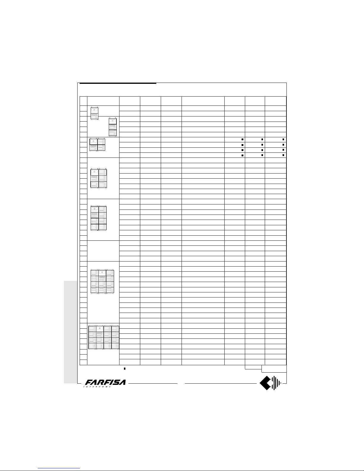
WITHOUT C
OAX *
WITH
COAX
56
(GB- '99)
-
-
-
-
-
-
-
-
-
1*
1*
1*
1*
-
-
-
1*
1*
1*
1*
-
-
-
-
-
-
-
2*
2*
2*
2*
1*
-
-
-
-
-
-
3*
3*
-
-
-
-
-
-
1 MD40D
1 MD40D
1 MD40D
1 MD40D
1 MD40D
1 MD40D
1 MD40D
1 MD40D
1 MD40D
1 MD40D
1 MD40D
1 MD40D
1 MD40D
1 MD40D
1 MD40D
1 MD40D
1 MD40D
1 MD40D
1 MD40D
1 MD40D
1 MD40D
1 MD40D
1 MD40D
1 MD40D
1 MD40D
1 MD40D
1 MD40D
1 MD40D
1 MD40D
1 MD40D
1 MD40D
1 MD40D
1 MD40D
1 MD40D
1 MD40D
1 MD40D
1 MD40D
1 MD40D
1 MD40D
1 MD40D
1 MD40D
1 MD40D
1 MD40D
1 MD40D
1 MD40D
1 MD40D
1 MD40D
1 MD40D
1 MD40D
1 MD40D
1 MD11D
1 MD12D
1 MD10D
1 MD10D
1 MD11D
1 MD12D
1 MD10D
1 MD10D
1 MD11D
1 MD12D
1 MD10D
1 MD10D
1 MD11D
1 MD12D
1 MD10D
1 MD10D
1 MD11D
1 MD12D
1 MD10D
1 MD10D
1 MD11D
1 MD12D
1 MD12D
1 MD12D
1 MD12D
1 MD12D
1 MD11D
1 MD10D
1 MD11D
1 MD12D
1 MD11D
1 MD12D
1 MD11D
1 MD12D
1 MD12D
1 MD12D
1 MD11D
1 MD12D
1 MD11D
1 MD12D
1 MD12D
1 MD12D
1 MD12D
1 MD10D
1 MD11D
1 MD12D
1 MD10D
1 MD11D
1 MD12D
1 MD10D
-
2 241D
2 241D
2 241D
2 241D
4 241D
4 241D
4 241D
4 241D
6 241D
6 241D
6 241D
6 241D
8 241D
8 241D
8 241D
8 241D
10 241D
10 241D
10 241D
10 241D
11 241D
11 241D
12 241D
12 241D
14 241D
14 241D
14 241D
14 241D
16 241D
16 241D
16 241D
16 241D
17 241D
18 241D
18 241D
18 241D
20 241D
20 241D
20 241D
20 241D
22 241D
22 241D
22 241D
22 241D
25 241D
25 241D
25 241D
25 241D
* MODY * E
RREP/R *
PROJECT * P
UNTOVIRGOLA *
SLIM
1 row push-button
-
1 MD23
1 MD24
1 MD24
1 MD24
1 MD24
2 MD24
2 MD24
2 MD24
2 MD24
3 MD24
3 MD24
3 MD24
3 MD24
4 MD24
4 MD24
4 MD24
4 MD24
5 MD24
5 MD24
5 MD24
5 MD24
5 MD24
5 MD24
6 MD24
5 MD24
7 MD24
7 MD24
7 MD24
6 MD24
6 MD24
8 MD24
8 MD24
8 MD24
8 MD24
8 MD24
8 MD24
8 MD24
8 MD24
9 MD24
10 MD24
8 MD24
11 MD24
11 MD24
11 MD24
11 MD24
11 MD24
11 MD24
11 MD24
1 MD72
1 MD72
1 MD73
1 MD73
1 MD73
1 MD73
2 MD72
2 MD72
2 MD72
2 MD72
2 MD73
2 MD73
2 MD73
2 MD73
2 MD73
2 MD73
2 MD73
2 MD73
2 MD74
2 MD74
2 MD74
2 MD74
2 MD74
2 MD74
2 MD74
2 MD74
3 MD73
3 MD73
3 MD73
3 MD73
3 MD74
3 MD74
3 MD74
3 MD74
3 MD74
3 MD74
3 MD74
3 MD74
3 MD74
3 MD74
3 MD74
3 MD74
4 MD74
4 MD74
4 MD74
4 MD74
4 MD74
4 MD74
4 MD74
4 MD74
1 MD82
1 MD82
1 MD83
1 MD83
1 MD83
1 MD83
1 MD84
1 MD84
1 MD84
1 MD84
1 MD86
1 MD86
1 MD86
1 MD86
1 MD86
1 MD86
1 MD86
1 MD86
1 MD808
1 MD808
1 MD808
1 MD808
1 MD808
1 MD808
1 MD808
1 MD808
1 MD89
1 MD89
1 MD89
1 MD89
1 MD812
1 MD812
1 MD812
1 MD812
1 MD812
1 MD812
1 MD812
1 MD812
1 MD812
1 MD812
1 MD812
1 MD812
-
-
-
-
-
-
-
-
1 MD92
1 MD92
1 MD93
1 MD93
1 MD93
1 MD93
1 MD94
1 MD94
1 MD94
1 MD94
1 MD96
1 MD96
1 MD96
1 MD96
1 MD96
1 MD96
1 MD96
1 MD96
1 MD908
1 MD908
1 MD908
1 MD908
1 MD908
1 MD908
1 MD908
1 MD908
1 MD99
1 MD99
1 MD99
1 MD99
1 MD912
1 MD912
1 MD912
1 MD912
1 MD912
1 MD912
1 MD912
1 MD912
1 MD912
1 MD912
1 MD912
1 MD912
-
-
-
-
-
-
-
-
248x395x19
(9
3
/4" x 15 9/16" x
3
/4")
372x395x19
(14
5
/8" x 15 9/16" x
3
/4")
1
2
3
4
5
6
7
8
9
10
11
12
13
14
15
16
17
18
19
20
21
22
23
24
25
26
27
28
29
30
31
32
33
34
35
36
37
38
39
40
41
42
43
44
45
46
47
48
49
50
-
-
-
-
-
-
1 MD23
-
-
-
1 MD23
-
-
-
1 MD23
-
-
-
1 MD23
-
-
1 MD21
1 MD22
1 MD23
2 MD23
-
-
2 MD23
2 MD23
-
1 MD21
2 MD21
2 MD22
2 MD22
2 MD23
2 MD23
1 MD23
3 MD23
-
-
3 MD21
3 MD21
3 MD21
3 MD22
496x395x19
(19
1
/2" x 15 9/16" x
3
/4")
or MD74 or MD804 or MD904 * or MD20 or MD50 or FC52
Optional It replaces
MD72, 73, 74
MODY series
Composition board of Mody push-button panels.
4+1 VIDEO-INTERCOM SYSTEM
Rain
shelter
Hood
covers
Back box and
module frame
Button and info or
blank modules
2 diode
module
Module with
speaker
Camera
module
Compositions and
dimensions
N°
calls
124x213x19
(4
7
/8"x 83/8"x 3/4")
124x304.5x19
(4
7
/8" x 12" x
3
/4")
248x213x19
(9
3
/4" x 8 3/8" x
3
/4")
248x304.5x19
(9
3
/4" x 12" x
3
/4")
372x304.5x19
(14
5
/8" x 12" x
3
/4")
Page 58
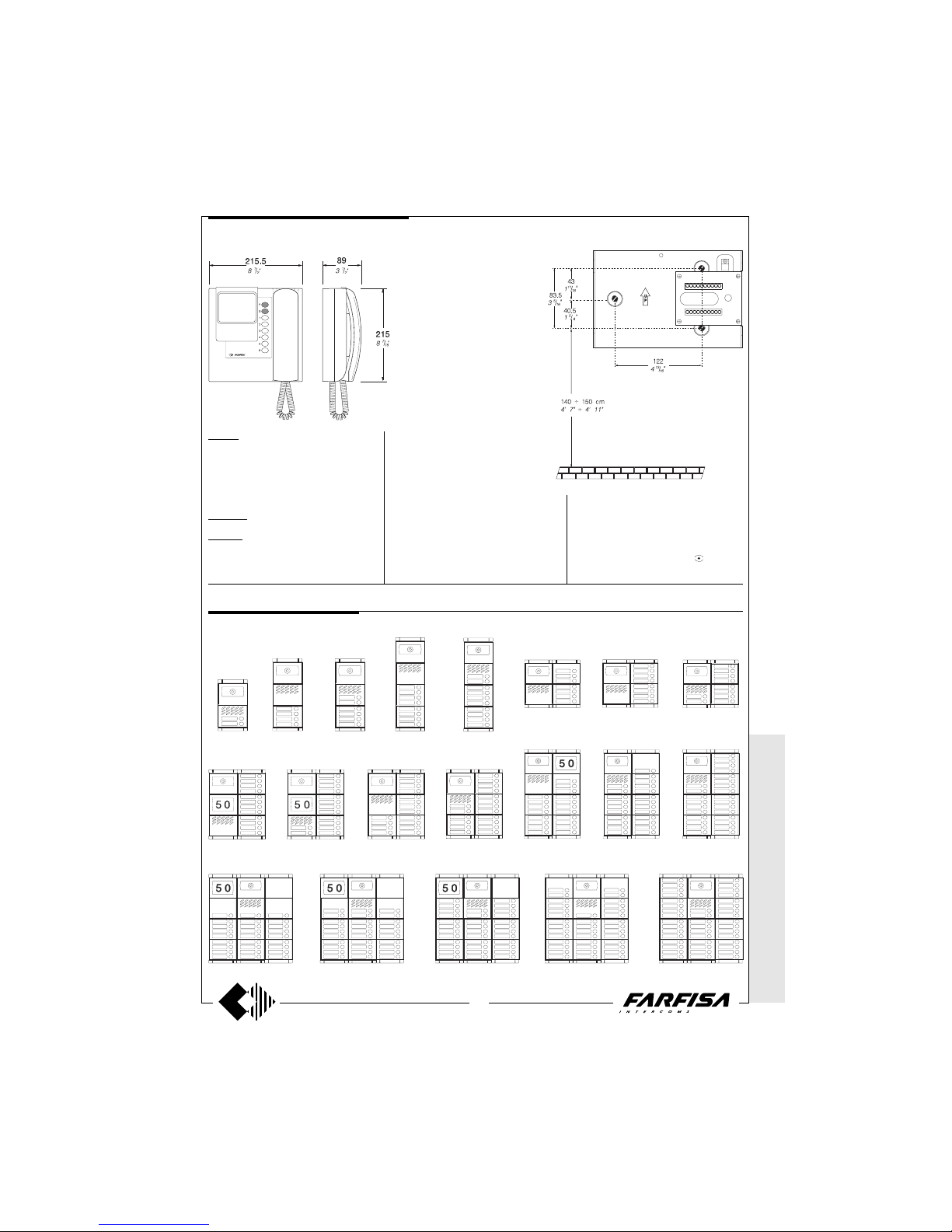
WITHOUT
COAX *
WITH COAX
57
(GB- '99)
* MODY *
ERREP/R
* PROJECT *
PUNTO
VIRGOLA *
SLIM
MODY series Example of Mody push-button panel installations.
PUSH-BUTTON PANELS
1 row push-button
2 call buttons 4 call buttons 6 call buttons 8 call buttons 10 call buttons
12 call buttons 14 call buttons 16 call buttons 18 call buttons 19 call buttons 23 call buttons 26 call buttons
10 call buttons8 call buttons7 call buttons
27 call buttons 30 call buttons 34 call buttons 37 call buttons 42 call buttons
PT5111. Two-colour flat monitor with two
buttons, one for control switch ON and one for
door lock release, audio-video privacy, electronic microphone, electronic modulated call
note, terminal board for the connection to the
wall-bracket. It can be installed on the wall
(with no built-in) by using the art.WB5111.
PT5111W. Colour: white.
WB5111. Wall-bracket for the PT5111 and
PT5111W monitors. It includes a terminal
board for connection to the system.
Terminals
H Positive power supply input 18÷24Vdc-
0.35A
F Ground
X and Y Video signal input
10 Call, audio reception/transmission,
door releasing
4 Control switch ON - button
Monitors series Project
Measures for the installation of the
wall bracket WB5111 to the wall, and
recommended height from the floor.
Technical data
Power Supply 18÷24Vdc
Operating current 0.35A
Video tube 4" FLAT CRT
Television standard 625 lines
Horizontal frequency 15625Hz
Vertical frequency 50Hz
Bandwidth >5MHz
Balanced video signal
Starting up time 2÷4 sec.
Operating temperature 0°÷+50°C
Max. permissible humidity 90%RH
4+1 VIDEO-INTERCOM SYSTEM
Page 59
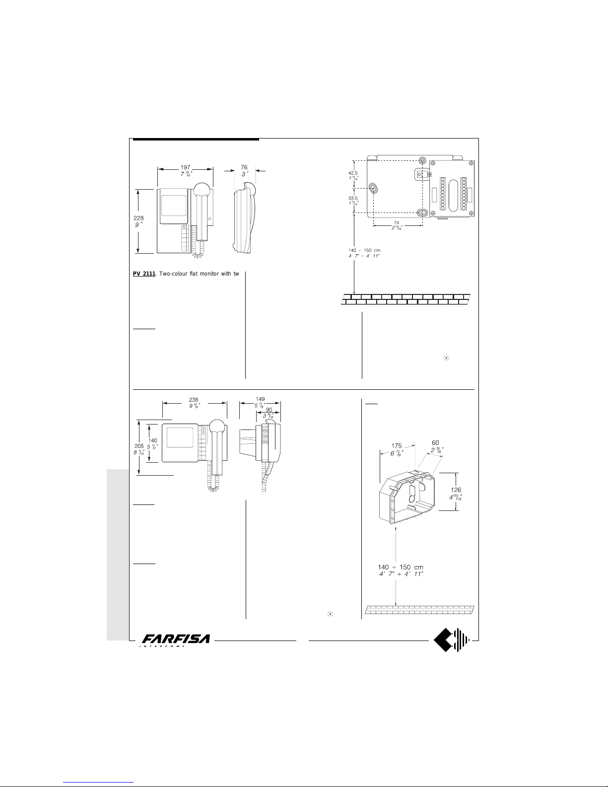
WITHOUT C
OAX *
WITH
COAX
58
(GB- '99)
aaaaaaaaaaaaaaaaaaaa
PV 2111. Two-colour flat monitor with two
buttons, one for control switch ON and one for
door lock release, audio-video privacy, electronic microphone, electronic modulated call
note, terminal board for the connection to the
wall-bracket. It can be installed on the wall
(with no built-in) by using the art.WB2111.
WB 2111. Wall-bracket for the PV2111 monitor. It includes a terminal board for connection to the system.
Technical data
Power Supply 18÷24Vdc
Operating current 0.35A
Video tube 4" FLAT CRT
Television standard 625 lines
Horizontal frequency 15625Hz
Vertical frequency 50Hz
Bandwidth >5MHz
Balanced video signal
Starting up time 2÷4 sec.
Operating temperature 0°÷+50°C
Max. permissible humidity 90%RH
Terminals
H Positive power supply input 18÷24Vdc-
0.35A
F Ground
X and Y Video signal input
10 Call, audio reception/transmission,
door releasing
4 Control switch ON - button
1283. Back-box for monitor PV1211.
Place the box on the wall at a height of about
1.5m (4' 11") from the floor keeping the front
edges flush-mounted and vertical to the finished plaster.
Monitors series PuntoVirgola
PV 1211. Two-colour monitor with traditional
tube with two buttons, one for control switch
ON and one for door lock release, audiovideo privacy, electronic microphone, electronic modulated call note, terminal board for
the connection to the wall-bracket. It can be
installed on the wall by using the art.WB1211
and the back-box art.1283.
WB 1211. Wall-bracket for the PV1211 monitor. It includes a terminal board for connection to the system.
Technical data
Power Supply 18÷24Vdc
Operating current 0.6A
Video tube 4.5" CRT
Television standard 625 lines
Horizontal frequency 15625Hz
Vertical frequency 50Hz
Bandwidth >5MHz
Balanced video signal
Starting up time 5÷7 sec.
Operating temperature 0°÷+50°C
Max. permissible humidity 90%RH
Terminals
H Positive power supply input 18÷24Vdc-
0.6A
F Ground
X and Y Video signal input
10 Call, audio reception/transmission,
door releasing
4 Control switch ON - button
* MODY *
ERREP/R
* PROJECT *
PUNTO
VIRGOLA * S
LIM
Measures for the installation of the
wall bracket WB2111 to the wall, and
recommended height from the floor.
4+1 VIDEO-INTERCOM SYSTEM
Page 60
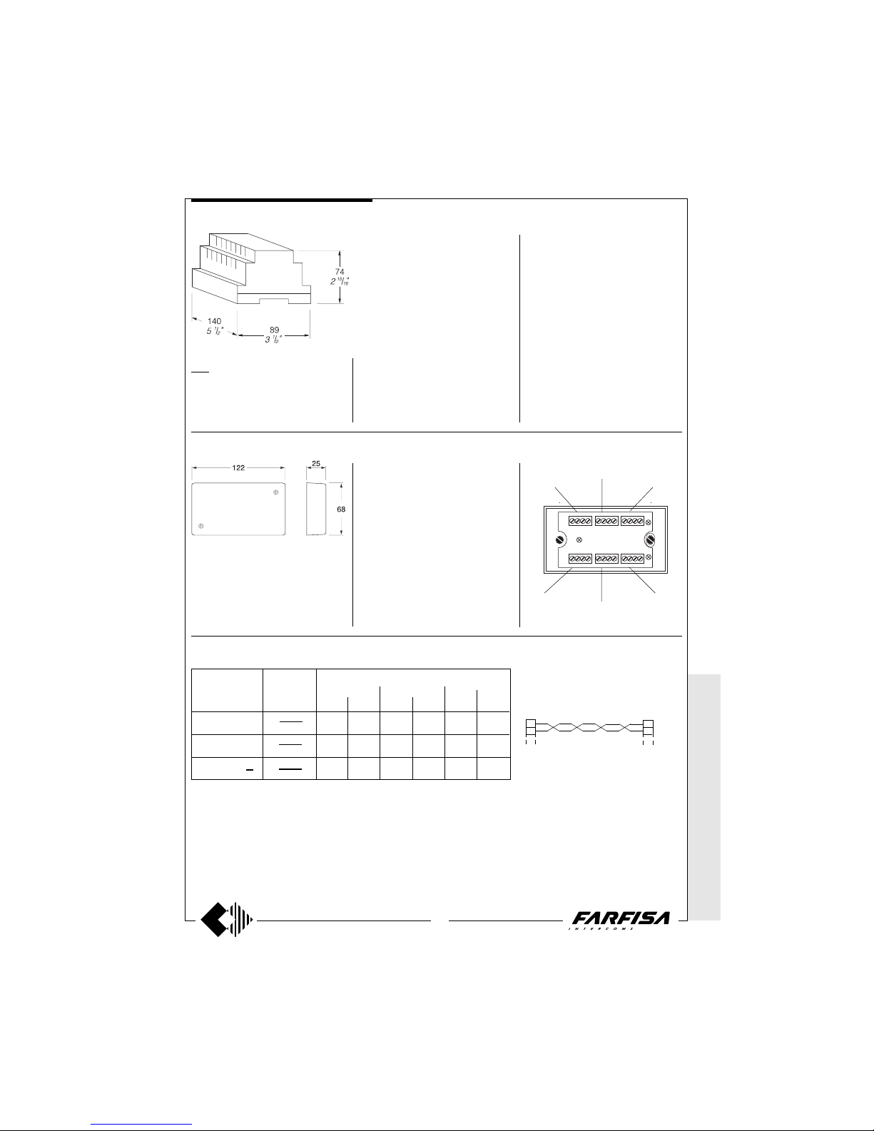
WITHOUT
COAX *
WITH COAX
59
(GB- '99)
1181. Timed supply for one monitor (or two
Flat monitors) CCD camera, electric lock and
push-button lights, etc.
Note
- The power supply is not provided with fuses,
but all of its outputs are protected against
overloading and short circuiting by temperature sensors. To reset the power supply, power must be cut off for about one minute and
can be restored after having eliminated the
defect.
- The power supply must be installed in a dry
place and can be fixed on DIN bar or on a wall
by using the expansion plugs.
Floor distributors
DV2D. Distributor at 2 outputs.
DV4D. Distributor at 4 outputs.
This unit allows video signal distribution for
the 4+1 system without coaxial cable. They
can be wall mounted or recessed in a junction
box.
Technical data
Power supply 21±2Vdc
Operating current 60mA
Max input video signal 2Vpp
Insertion loss 0.8dB
Bandwidth >5MHz
Terminals
H Input / output positive power supply
F Ground
X and Y Input / output video signal
Note
The two 150Ω resistors, included with the
product, must be applied to connectors Y-F
and X-F on the last distributor only.
Leave other terminals free.
WIRE CROSS SECTION
Distance
Note.
For distances longer than 100m (330ft) max
200m (660ft), use twisted pair wire for
conductores X and Y.
X3Y3H F
X
4Y4
H F
F H Y X
F H Y X
F H Y
2X2
F H Y1X
1
to monitorto monitor
to monitor
to monitor
X
Y
X
Y
to following distributors
from previous distributors
* MODY * E
RREP/R *
PROJECT *
PUNTOVIRGOLA *
SLIM
Power supply
Technical data
Input voltage 127 o 230Vac
Frequency 50/60Hz
Power 48VA
Switch-ON time: 100 sec.
Operating temperature 0°÷+50°C
Maximum permissible humidity 90%RH
Housing DIN 8 modules A
Weight 0.95Kg.
Terminals
A Output voltage 13Vac for:
-name plate light, exchangers and climatized
camera (continuous service 0.6A)
-electric door lock and bells (intermittent
service 1A)
- Ground for AC power supply
F Ground for DC power supply
H
Continuous output 21Vdc-1A
(timed operation)
D Alternating voltage output for the common of
pushbutton 13Vac-0.5A (intermittent service)
660 Ft
AWG
22
16
16
50m
S mm²
0.35
0.5
0.75
165 Ft
AWG
22
20
18
100m
S mm²
0.35
0.75
1
330 Ft
AWG
22
18
16
200m
S mm²
0.35
1
1.5
Installation notes
For correct installation of the video intercom
systems, the following regulations have to be
respected:
- The wires of the system have to run in a
channelling separated from the mains.
- Use section wires adequate to the maximum
distance of the system.
- Link the - (minus) and F terminals directly on
the external station, and not on the power
supply. Both the wires are needed, to avoid
possible hum on the sound channels.
Diagram lines
Terminals articles
X - Y
10 - D - 1 - C
F - H - A - S -
4+1 VIDEO-INTERCOM SYSTEM
Page 61
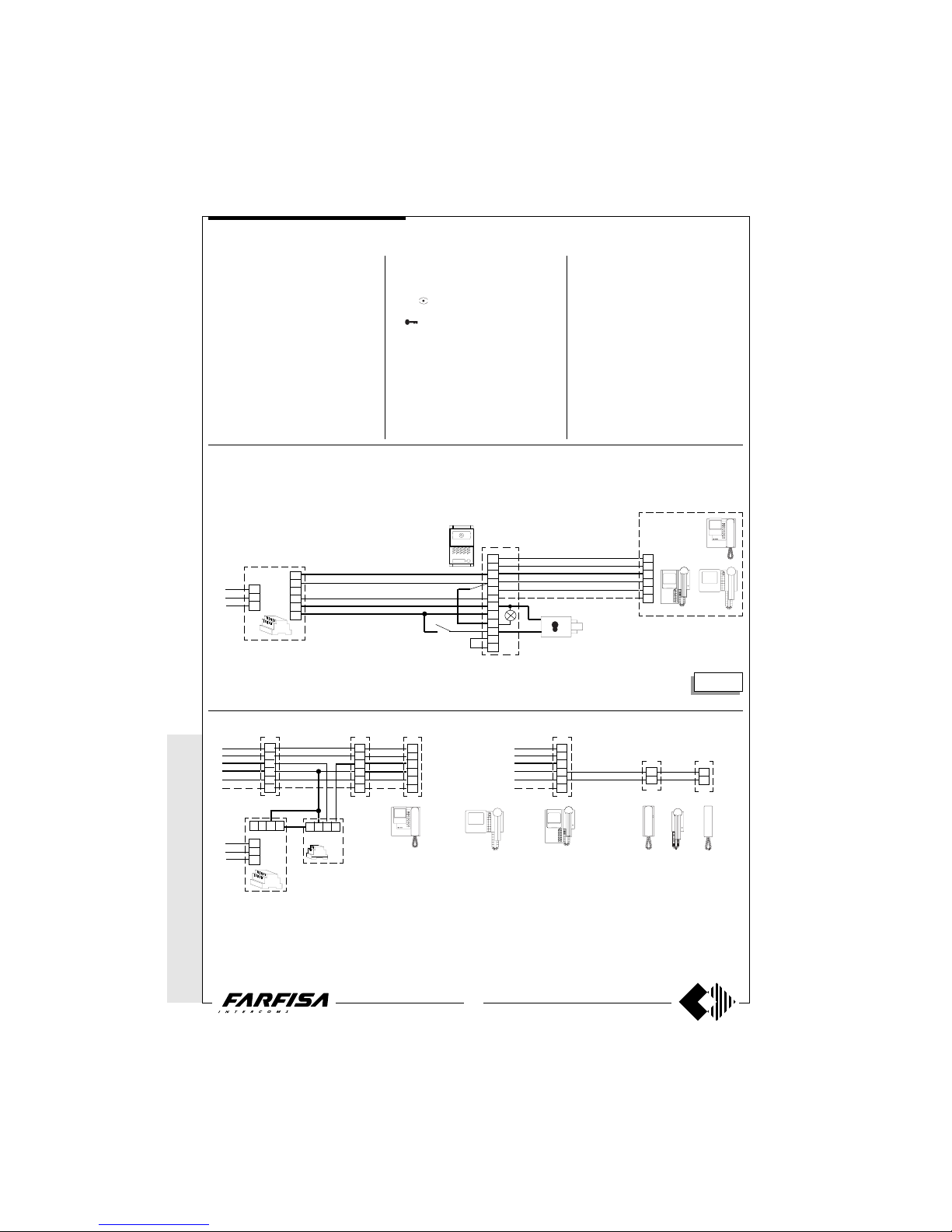
WITHOUT C
OAX *
WITH
COAX
60
(GB- '99)
Check that the connections of the system are
carried out correctly.
Put the system in use by connecting the
power supply to the mains.
By pushing a call button from the external
push-button panel, it activates the bell of the
corresponding monitor and it activates the
system for a time of about 100 seconds. The
images appear on the monitor a few seconds
after the call.
If in the meantime another call occurs, the
monitor shuts itself off and connects the last
call. The system switches off automatically
after 100 sec.
In case more calls occur simultaneously, a
protection circuit against overloading and
short circuiting is provided to disable the
Working instructions
timer and therefore to shut off the system.
In the absence of calls from the door station,
from any monitor (if provided in the system) it
is possible to control the entrance by pressing the
button (control switch ON).
To work the electric door lock release press
the
button from monitors series Project
and PV 1211. For the FLAT PV2111 monitor
press the button to the right of the handset. In
the two or more entrance systems all the
audio and video communications and door
lock release, from one entrance to the other,
are automatically switched with the call or the
control switch ON.
In these systems the control switch ON from
the monitors can interrupt a running communication, for this reason it is advisable to
interrupt, by means of a relay art.1471, all the
control switches ON when the video system is
active, giving the priority of the communication to the door stations (see page 24).
Adjustments
All the regulations are carried out in the
factory. For possible corrections the intervention of a specialized technician is advisable. The Contrast and Brightness adjustments, being subject to the environmental
lighting conditions, are accessible from the
under-neath by means of a screw driver.
230V
127V
0
X
Y
H
F
P
C
A
-
-
S
1
E
PA
(optional)
SE
(12Vac-1A max)
H
F
D
A
-
MD40D
MD11D
MD72
X
Y
H
F
10
4
X
Y
H
F
10
4
X
Y
H
F
10
4
X
Y
H
F
10
4
5326
AI -+
230V
127V
0
1281
1471
Application of 3 parallel monitors
X
Y
H
F
10
4
Application of 1 monitor and 2 parallel systems
3
1
3
1
Installation diagrams
Note
In all the 4+1 video intercom systems it is possible to add
further monitors and/or intercoms. To do this, insert the 2
application examples in this page instead of the monitor
which has been represented in the various installation
systems of pages 60, 61, 62, 63.
PA = Door release button (optional)
SE = Electric door lock (12VAC-1A max.)
AL
IN
VC1
VC2 VC3 VC
CT1
CT2
PT511 PV111
Si 5800
924D
AL
1181
* MODY *
ERREP/R
* PROJECT *
PUNTO
VIRGOLA * S
LIM
VC =
PT5111 + WB5111
PV2111 + WB2111
PV1211 + WB1211 + 1283
VC
VC =
PT5111 + WB5111
PV2111 + WB2111
PV1211 + WB1211 + 1283
ONE WA Y VIDEO-INTERCOM SYSTEM
4+1 VIDEO-INTERCOM SYSTEM
Page 62
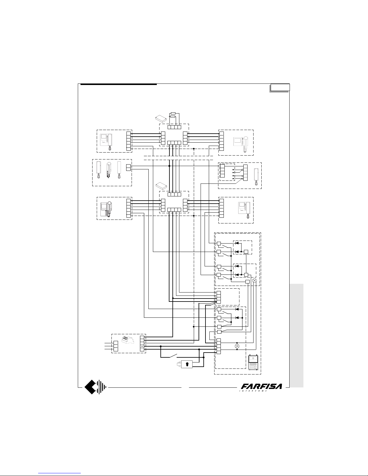
WITHOUT
COAX *
WITH COAX
61
(GB- '99)
1
-
-
A
S
X
Y
H
F
MD40D
H
F
D
A
1181
AL
230V
127V
0
SE
(optional)
E
P
P
P
P
PA
E
MD21 - MD22 - MD23 - MD24
MD222-MD224-MD226-MD228
241D
P
P
2 x
150Ω
FHYX
F
H
Y
X
10
4
VCn
F
H
Y
X
10
4
VCn
FHYX
F
H
Y2
X2
F
H
Y1
X1
3
1
-
-
B
C
3
2
6
1
CT
7
3
6
1
PT511 + SM50
DV2D
DV4D
FHYX
F
H
Y
X
10
4
VC1
F
H
Y
X
10
4
VC2
FHYX
F
H
Y2
X2
F
H
Y1
X1
DV2D
DV4D
241D
C
C
E
PA = Door release button (optional)
SE = Electric door lock (12VAC-1A max.)
MULTI-W AY COMBINED INTERCOM AND VIDEO INTERCOM SYSTEM
MD72 - MD73 - MD74
Si 5801
Intercom with private conversation.
CT
Intercom without private conversation.
MD10D
MD11D
MD12D
* MODY * E
RREP/R
* PROJECT *
PUNTOVIRGOLA *
SLIM
VC =
PT5111 + WB5111
PV2111 + WB2111
PV1211 + WB1211 + 1283
PT511 PV111 924D
4+1 VIDEO-INTERCOM SYSTEM
Note
In the modules with electric door speaker
MD10D, MD11D or MD12D, take out the
yellow wire linking the C terminal.
Page 63
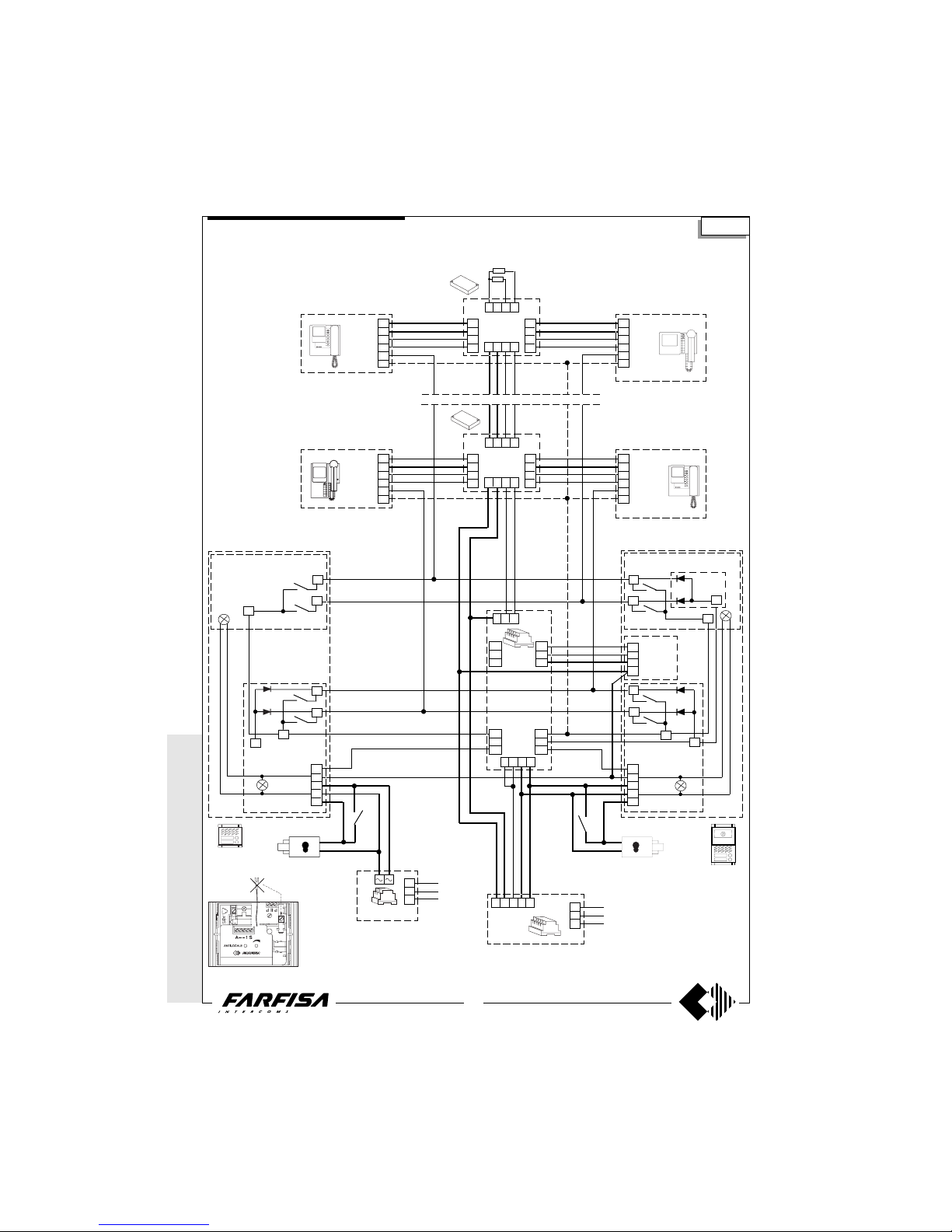
WITHOUT C
OAX *
WITH
COAX
62
(GB- '99)
MULTI-W AY VIDEO-INTERCOM SYSTEM WITH 2 AUTOMATICALLY SWITCHED VIDEO ENTRANCES,
ONE OF WHICH IS ONLY AUDIO.
Si 5850
987
7a
8a
9a
6
10
10a
1
-
-
A
S
X
Y
H
F
C
C
P
P
P
P
SE
PA
P
P
1
-
-
A
S
P
P
C
E
241D
E
7b
8b
9b
4
10b
3512
E
AL
1181
230V
127V
0
SE
PA
MD10D
MD11D
MD12D
MD10D
MD11D
MD12D
FHDA-
C
FHYX
F
H
Y
X
10
4
VC1
F
H
Y
X
10
4
VC2
FHYX
F
H
Y2
X2
F
H
Y1
X1
DV2D
DV4D
FHYX
F
H
Y
X
10
4
VCn
F
H
Y
X
10
4
VCn
FHYX
F
H
Y2
X2
F
H
Y1
X1
DV2D
DV4D
PA = Door release button (optional)
SE = Electric door lock (12VAC-1A max.)
DS
1473
MD40D
2 x
150Ω
AS PRS210
230V
127V
0
Note
In the modules with electric door speaker
MD10D, MD11D or MD12D, take out the
yellow wire linking the C terminal.
* MODY *
ERREP/R
* PROJECT *
PUNTO
VIRGOLA * S
LIM
VC =
PT5111 + WB5111
PV2111 + WB2111
PV1211 + WB1211 + 1283
4+1 VIDEO-INTERCOM SYSTEM
MD21 - MD22 - MD23 - MD24
MD222-MD224-MD226-MD228
MD72 - MD73 - MD74
MD21 - MD22 - MD23 - MD24
MD222-MD224-MD226-MD228
MD72 - MD73 - MD74
Page 64
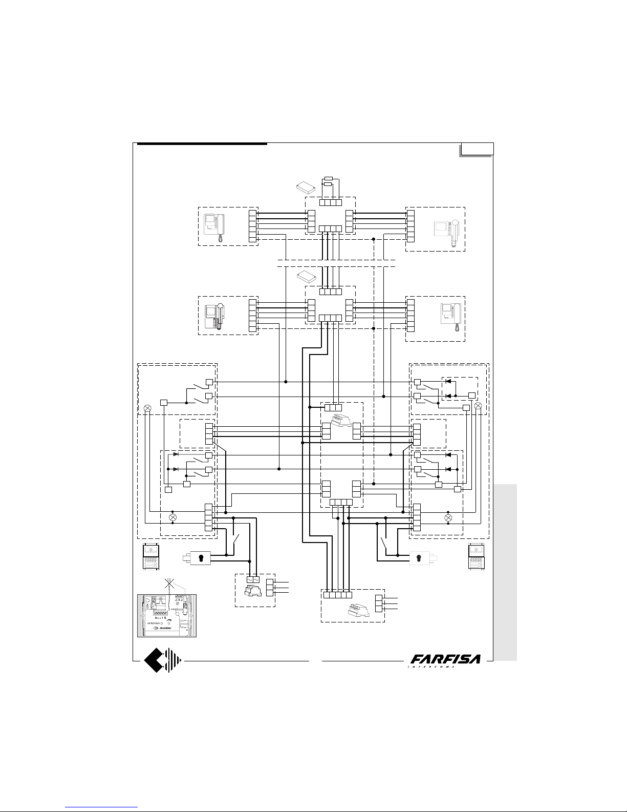
WITHOUT
COAX *
WITH COAX
63
(GB- '99)
MULTI-W AY VIDEO-INTERCOM SYSTEM WITH 2 AUTOMATICALLY SWITCHED VIDEO ENTRANCES.
Si 5851
987
7a
8a
9a
6
10
10a
1
-
-
A
S
X
Y
H
F
C
C
P
P
P
P
SE
PA
P
P
1
-
-
A
S
P
P
C
E
241D
E
7b
8b
9b
4
10b
3512
E
AL
1181
230V
127V
0
SE
PA
MD10D
MD11D
MD12D
MD10D
MD11D
MD12D
FHDA-
C
X
Y
H
F
MD40D
FHYX
F
H
Y
X
10
4
VC1
F
H
Y
X
10
4
VC2
FHYX
F
H
Y2
X2
F
H
Y1
X1
DV2D
DV4D
FHYX
F
H
Y
X
10
4
VCn
F
H
Y
X
10
4
VCn
FHYX
F
H
Y2
X2
F
H
Y1
X1
DV2D
DV4D
PA = Door release button (optional)
SE = Electric door lock (12VAC-1A max.)
DS
1473
MD40D
2 x
150Ω
AS PRS210
230V
127V
0
Note
In the modules with electric door speaker
MD10D, MD11D or MD12D, take out the
yellow wire linking the C terminal.
* MODY * E
RREP/R *
PROJECT *
PUNTOVIRGOLA *
SLIM
VC =
PT5111 + WB5111
PV2111 + WB2111
PV1211 + WB1211 + 1283
4+1 VIDEO-INTERCOM SYSTEM
MD21 - MD22 - MD23 - MD24
MD222-MD224-MD226-MD228
MD72 - MD73 - MD74
MD21 - MD22 - MD23 - MD24
MD222-MD224-MD226-MD228
MD72 - MD73 - MD74
 Loading...