

Page 1

GE Fanuc Automation
Computer Numerical Control Products
Super CAP T and Super CAP II T
for Series 16/18-TB, 16/18-TC, and 16i/18i-TA
Operator's Manual
GFZ-62444E-1/04 October 1997
Page 2

Warnings, Cautions, and Notes
as Used in this Publication
Warning notices are used in this publication to emphasize that hazardous voltages, currents,
temperatures, or other conditions that could cause personal injury exist in this equipment or
may be associated with its use.
In situations where inattention could cause either personal injury or damage to equipment, a
Warning notice is used.
Caution notices are used where equipment might be damaged if care is not taken.
GFL-001
Warning
Caution
Note
Notes merely call attention to information that is especially significant to understanding and
operating the equipment.
This document is based on information available at the time of its publication. While efforts
have been made to be accurate, the information contained herein does not purport to cover all
details or variations in hardware or software, nor to provide for every possible contingency in
connection with installation, operation, or maintenance. Features may be described herein
which are not present in all hardware and software systems. GE Fanuc Automation assumes
no obligation of notice to holders of this document with respect to changes subsequently made.
GE Fanuc Automation makes no representation or warranty, expressed, implied, or statutory
with respect to, and assumes no responsibility for the accuracy, completeness, sufficiency, or
usefulness of the information contained herein. No warranties of merchantability or fitness for
purpose shall apply.
PowerMotion is a trademark of GE Fanuc Automation North America, Inc.
©Copyright 1997 GE Fanuc Automation North America, Inc.
All Rights Reserved.
Page 3

SAFETY PRECAUTIONS
When using a machine equipped with the F ANUC Super CAP T and F ANUC Super CAP II T, be sure to observe
the following safety precautions.
s–1
Page 4
1
SAFETY PRECAUTIONS
B–62444E–1/04
DEFINITION OF WARNING, CAUTION, AND NOTE
This manual includes safety precautions for protecting the user and preventing damage to the
machine. Precautions are classified into W arning and Caution according to their bearing on safety.
Also, supplementary information is described as a Note. Read the Warning, Caution, and Note
thoroughly before attempting to use the machine.
WARNING
Applied when there is a danger of the user being injured or when there is a damage of both the user
being injured and the equipment being damaged if the approved procedure is not observed.
CAUTION
Applied when there is a danger of the equipment being damaged, if the approved procedure is not
observed.
NOTE
The Note is used to indicate supplementary information other than Warning and Caution.
Read this manual carefully, and store it in a safe place.
s–2
Page 5

B–62444E–1/04
2
SAFETY PRECAUTIONS
GENERAL WARNINGS AND CAUTIONS
WARNING
1.
Before starting to use the conversational functions (such as creation/run of machining programs,
measurement of tool compensation, and specification of a chuck barrier), close the doors of the
machine, and take any other necessary safety measures.
Failure to take a necessary safety measure may bring about the death of, or a serious injury to,
the user.
2.
Before going to the next step of handling or operation, check the display on the screen carefully
to assure that the intended data has been entered correctly.
If the machine is used with incorrect data, the tool may bump against the machine and/or
workpiece, possibly causing damage to the tool and/or machine, and even injuries.
3.
When you are using a tool compensation function, before starting the machine, check the
direction and amount of compensation so that the tool will not bump against the workpiece or
machine.
If the tool bumps against the machine and/or workpiece, the tool and/or machine may be
damaged, and even injuries may occur.
4.
After you create a machining program using a conversational function, do not run the machine
on that program immediately . Instead, carry out machining simulation to make sure that the tool
path and machining operation are correct and that the tool will not bump against the workpiece
or machine (including the chuck and tailstock).
If the tool bumps against the machine and/or workpiece, the tool and/or machine may be
damaged, and even injuries may occur.
5.
After you convert a machining program created using a conversational function to NC program
format, do not run the machine on that program immediately . Instead, confirm every step of the
resultant NC program, and make sure that the tool path and machining operation are correct and
that the tool will not bump against the workpiece or machine (including the chuck and tailstock).
Before starting production machining, run the machine with no workpiece attached to the
machine to make sure that the tool will not bump against a workpiece (when attached) or the
machine (including the chuck and tailstock).
If the tool bumps against the machine and/or workpiece, the tool and/or machine may be
damaged, and even injuries may occur.
6.
Before starting to create a machining program using a conversational function, make sure that
all necessary data among the tool data, cutting condition data, surface roughness data, pre–tool
list, and chuck and tailstock data, and all parameters necessary for the conversational function
are set correctly.
If the necessary data is not set correctly , any required cutting conditions will not be set correctly ,
possibly causing damage to the tool, and even injuries.
s–3
Page 6

SAFETY PRECAUTIONS
B–62444E–1/04
W ARNING
7.
When you run the machine using a machining program created using a conversational function
or a machining program generated by converting another machining program to NC program
format, be sure to use the correct tool geometry compensation data measured on the relevant
measurement guidance screen provided by the conversational function.
If the machine is used with incorrect data, the tool may bump against the machine and/or
workpiece, possibly causing damage to the tool and/or machine, and even injuries.
The method to measure the tool compensation amount may be provided by the machine tool
builder. If this is the case, before starting measurement, read carefully and understand
sufficiently the applicable user’s guide from the machine tool builder.
8.
Before using a chuck barrier or chuck/tailstock barrier, perform a manual operation (such as jog
feed or manual pulse generator feed) to make sure that the barrier area data is set correctly , that
the barrier function occurs at the correct position, and that the tool will not bump against the
chuck or tailstock.
If the tool bumps against the chuck and/or tailstock, the tool and/or machine may be damaged,
and even injuries may occur.
9.
When pressing the power ON button, do not touch any key on the keyboard before a display
appears on the screen. Some keys on the keyboard are allocated to maintenance or other special
operations. Pressing any of these keys may cause the machine to behave unexpectedly.
s–4
Page 7

B–62444E–1/04
Table of Contents
SAFETY PRECAUTIONS s–1. . . . . . . . . . . . . . . . . . . . . . . . . . . . . . . . . . . . . . . . . . . . . . . . . . . . .
I. GENERAL
1. OVERVIEW 3. . . . . . . . . . . . . . . . . . . . . . . . . . . . . . . . . . . . . . . . . . . . . . . . . . . . . . . . . . . . . . . .
2. SYMBOLS USED 5. . . . . . . . . . . . . . . . . . . . . . . . . . . . . . . . . . . . . . . . . . . . . . . . . . . . . . . . . . .
3. FLOWCHART FROM CREATING A PROGRAM TO EXECUTING IT 6. . . . . . . . . . . . . .
3.1 CREATING A MACHINING PROGRAM 7. . . . . . . . . . . . . . . . . . . . . . . . . . . . . . . . . . . . . . . . . . . . . . .
3.2 CHECKING A MACHINING PROGRAM 8. . . . . . . . . . . . . . . . . . . . . . . . . . . . . . . . . . . . . . . . . . . . . .
3.3 SELECTING A MACHINING PROGRAM TO BE EXECUTED 9. . . . . . . . . . . . . . . . . . . . . . . . . . . .
4. SELECTING THE MENU AND INPUTTING DATA 10. . . . . . . . . . . . . . . . . . . . . . . . . . . . .
4.1 SOFT KEYS 11. . . . . . . . . . . . . . . . . . . . . . . . . . . . . . . . . . . . . . . . . . . . . . . . . . . . . . . . . . . . . . . . . . . . .
4.2 CALCULATION FUNCTIONS SIMILAR TO THOSE OF A HAND–HELD CALCULATOR 12. . . .
4.2.1 Operation for Calculation 12. . . . . . . . . . . . . . . . . . . . . . . . . . . . . . . . . . . . . . . . . . . . . . . . . . . . . . .
4.2.2 Keys for Calculation 14. . . . . . . . . . . . . . . . . . . . . . . . . . . . . . . . . . . . . . . . . . . . . . . . . . . . . . . . . . .
5. HIERARCHY OF THE CONVERSATIONAL SCREENS 15. . . . . . . . . . . . . . . . . . . . . . . . .
II. OPERATION
1. OVERVIEW OF THE PROCEDURE 19. . . . . . . . . . . . . . . . . . . . . . . . . . . . . . . . . . . . . . . . . .
2. DESCRIPTION OF THE KEYBOARD 21. . . . . . . . . . . . . . . . . . . . . . . . . . . . . . . . . . . . . . . .
2.1 KEYBOARD TYPES 22. . . . . . . . . . . . . . . . . . . . . . . . . . . . . . . . . . . . . . . . . . . . . . . . . . . . . . . . . . . . . .
2.2 DETAILS OF THE KEYBOARD 23. . . . . . . . . . . . . . . . . . . . . . . . . . . . . . . . . . . . . . . . . . . . . . . . . . . . .
3. OPERATION MODES 26. . . . . . . . . . . . . . . . . . . . . . . . . . . . . . . . . . . . . . . . . . . . . . . . . . . . . .
4. TYPES OF SCREENS 28. . . . . . . . . . . . . . . . . . . . . . . . . . . . . . . . . . . . . . . . . . . . . . . . . . . . . .
4.1 ONE–PATH LATHES 29. . . . . . . . . . . . . . . . . . . . . . . . . . . . . . . . . . . . . . . . . . . . . . . . . . . . . . . . . . . . . .
4.2 TWO–PATH LATHES 37. . . . . . . . . . . . . . . . . . . . . . . . . . . . . . . . . . . . . . . . . . . . . . . . . . . . . . . . . . . . . .
5. DESCRIPTION OF COORDINATE SYSTEMS 43. . . . . . . . . . . . . . . . . . . . . . . . . . . . . . . . .
5.1 ONE–PATH LATHER 44. . . . . . . . . . . . . . . . . . . . . . . . . . . . . . . . . . . . . . . . . . . . . . . . . . . . . . . . . . . . . .
5.1.1 Machine Coordinate System 44. . . . . . . . . . . . . . . . . . . . . . . . . . . . . . . . . . . . . . . . . . . . . . . . . . . . .
5.1.2 Workpiece Coordinate System 45. . . . . . . . . . . . . . . . . . . . . . . . . . . . . . . . . . . . . . . . . . . . . . . . . . .
5.1.3 Program Coordinate System 46. . . . . . . . . . . . . . . . . . . . . . . . . . . . . . . . . . . . . . . . . . . . . . . . . . . . .
c–1
Page 8

T ABLE OF CONTENTS
5.2 TWO–PATH LATHES WITH TWO OPPOSING SPINDLES 47. . . . . . . . . . . . . . . . . . . . . . . . . . . . . . .
5.2.1 Machine Coordinate System 47. . . . . . . . . . . . . . . . . . . . . . . . . . . . . . . . . . . . . . . . . . . . . . . . . . . . .
5.2.2 Workpiece Coordinate System 48. . . . . . . . . . . . . . . . . . . . . . . . . . . . . . . . . . . . . . . . . . . . . . . . . . .
5.2.3 Program Coordinate System 49. . . . . . . . . . . . . . . . . . . . . . . . . . . . . . . . . . . . . . . . . . . . . . . . . . . . .
5.3 FOR TWO–PATH LATHES WITH ONE SPINDLE 50. . . . . . . . . . . . . . . . . . . . . . . . . . . . . . . . . . . . . .
5.3.1 Machine Coordinate System 50. . . . . . . . . . . . . . . . . . . . . . . . . . . . . . . . . . . . . . . . . . . . . . . . . . . . .
5.3.2 Workpiece Coordinate System 51. . . . . . . . . . . . . . . . . . . . . . . . . . . . . . . . . . . . . . . . . . . . . . . . . . .
5.3.3 Program Coordinate System 52. . . . . . . . . . . . . . . . . . . . . . . . . . . . . . . . . . . . . . . . . . . . . . . . . . . . .
B–62444E–1/04
6. CREATING MACHINING PROGRAMS 53. . . . . . . . . . . . . . . . . . . . . . . . . . . . . . . . . . . . . . .
6.1 FORMAT OF MACHINING PROGRAM USED FOR THE ONE–PATH LATHES 54. . . . . . . . . . . . .
6.2 FORMAT OF MACHINING PROGRAM USED FOR THE TWO–PATH LATHES 55. . . . . . . . . . . . .
6.3 SELECTING THE CONVERSATIONAL MODE 56. . . . . . . . . . . . . . . . . . . . . . . . . . . . . . . . . . . . . . . .
6.4 CREATING A MACHINING PROGRAM 57. . . . . . . . . . . . . . . . . . . . . . . . . . . . . . . . . . . . . . . . . . . . . .
6.4.1 Entering the Number and Name of a Program 57. . . . . . . . . . . . . . . . . . . . . . . . . . . . . . . . . . . . . . .
6.5 INITIAL SETTINGS 58. . . . . . . . . . . . . . . . . . . . . . . . . . . . . . . . . . . . . . . . . . . . . . . . . . . . . . . . . . . . . . .
6.5.1 Details of Settings 58. . . . . . . . . . . . . . . . . . . . . . . . . . . . . . . . . . . . . . . . . . . . . . . . . . . . . . . . . . . . .
6.5.2 Operation for Initial Settings 64. . . . . . . . . . . . . . . . . . . . . . . . . . . . . . . . . . . . . . . . . . . . . . . . . . . .
6.6 PROCESS DATA SCREEN 65. . . . . . . . . . . . . . . . . . . . . . . . . . . . . . . . . . . . . . . . . . . . . . . . . . . . . . . . . .
6.6.1 Operation for the Process Data Screen 66. . . . . . . . . . . . . . . . . . . . . . . . . . . . . . . . . . . . . . . . . . . . .
6.7 FIGURE DATA SCREEN 68. . . . . . . . . . . . . . . . . . . . . . . . . . . . . . . . . . . . . . . . . . . . . . . . . . . . . . . . . . .
6.7.1 Operation on the Contour Data Screen 68. . . . . . . . . . . . . . . . . . . . . . . . . . . . . . . . . . . . . . . . . . . . .
6.7.2 Operation for Data other than Contour Data on the Figure Data Screen 70. . . . . . . . . . . . . . . . . . .
6.8 CREATING A NEW PROGRAM USING OTHER PROGRAMS 72. . . . . . . . . . . . . . . . . . . . . . . . . . . .
6.8.1 Registered–program Directory Screen for Editing 72. . . . . . . . . . . . . . . . . . . . . . . . . . . . . . . . . . . .
6.8.2 Copying a Program 72. . . . . . . . . . . . . . . . . . . . . . . . . . . . . . . . . . . . . . . . . . . . . . . . . . . . . . . . . . . .
7. CHECKING MACHINING PROGRAMS 73. . . . . . . . . . . . . . . . . . . . . . . . . . . . . . . . . . . . . . .
7.1 CHECKING INPUT FIGURES 74. . . . . . . . . . . . . . . . . . . . . . . . . . . . . . . . . . . . . . . . . . . . . . . . . . . . . .
7.1.1 Registered–program Directory Screen for Editing 74. . . . . . . . . . . . . . . . . . . . . . . . . . . . . . . . . . . .
7.1.2 Specifying the Program to be Edited 74. . . . . . . . . . . . . . . . . . . . . . . . . . . . . . . . . . . . . . . . . . . . . .
7.1.3 Displaying the Contents of the Machining Program 74. . . . . . . . . . . . . . . . . . . . . . . . . . . . . . . . . . .
7.1.4 Enlarging the Part of the Contour 76. . . . . . . . . . . . . . . . . . . . . . . . . . . . . . . . . . . . . . . . . . . . . . . . .
7.1.5 End of Checking Machining Programs 76. . . . . . . . . . . . . . . . . . . . . . . . . . . . . . . . . . . . . . . . . . . . .
7.2 CHECKING MACHINING PROGRAMS USING THE SIMULATION 77. . . . . . . . . . . . . . . . . . . . . .
7.2.1 Selecting a Machining Program 78. . . . . . . . . . . . . . . . . . . . . . . . . . . . . . . . . . . . . . . . . . . . . . . . . .
7.2.2 Simulating Machining 80. . . . . . . . . . . . . . . . . . . . . . . . . . . . . . . . . . . . . . . . . . . . . . . . . . . . . . . . . .
7.2.3 Enlarging a Figure and Displaying Other Screens 83. . . . . . . . . . . . . . . . . . . . . . . . . . . . . . . . . . . .
7.3 SIMULATION OF Y–AXIS MACHINING 85. . . . . . . . . . . . . . . . . . . . . . . . . . . . . . . . . . . . . . . . . . . . .
7.3.1 Simulation of Y–axis Machining by a One–path Lathe 85. . . . . . . . . . . . . . . . . . . . . . . . . . . . . . . .
7.3.2 Simulation of Y–axis Machining by a Two–path Lathe 86. . . . . . . . . . . . . . . . . . . . . . . . . . . . . . . .
7.4 OFFSET DATA SAVE AND RESTORE FUNCTION 87. . . . . . . . . . . . . . . . . . . . . . . . . . . . . . . . . . . . .
7.4.1 Generals 87. . . . . . . . . . . . . . . . . . . . . . . . . . . . . . . . . . . . . . . . . . . . . . . . . . . . . . . . . . . . . . . . . . . .
7.4.2 Parameter 87. . . . . . . . . . . . . . . . . . . . . . . . . . . . . . . . . . . . . . . . . . . . . . . . . . . . . . . . . . . . . . . . . . .
7.4.3 Details 88. . . . . . . . . . . . . . . . . . . . . . . . . . . . . . . . . . . . . . . . . . . . . . . . . . . . . . . . . . . . . . . . . . . . . .
7.4.4 Execution Selection State Display 89. . . . . . . . . . . . . . . . . . . . . . . . . . . . . . . . . . . . . . . . . . . . . . . .
7.4.5 Tool Changing Position Temporary Setting 90. . . . . . . . . . . . . . . . . . . . . . . . . . . . . . . . . . . . . . . . .
7.4.6 Alternation of G30 Command in Macro Program 90. . . . . . . . . . . . . . . . . . . . . . . . . . . . . . . . . . . .
c–2
Page 9

B–62444E–1/04
7.5 MACHINING SIMULATION BASED ON A SOLID MODEL (SUPER CAP II T) 91. . . . . . . . . . . . .
7.5.1 Simulating a Cutting Operation Based on a Solid Model 91. . . . . . . . . . . . . . . . . . . . . . . . . . . . . . .
7.5.2 Simulation of C–/Y–axis Machining 91. . . . . . . . . . . . . . . . . . . . . . . . . . . . . . . . . . . . . . . . . . . . . .
T ABLE OF CONTENTS
8. EDITING MACHINING PROGRAMS 94. . . . . . . . . . . . . . . . . . . . . . . . . . . . . . . . . . . . . . . . .
8.1 SELECTING THE MACHINING PROGRAM TO BE EDITED 95. . . . . . . . . . . . . . . . . . . . . . . . . . . .
8.1.1 Registered–program Directory Screen for Editing 95. . . . . . . . . . . . . . . . . . . . . . . . . . . . . . . . . . . .
8.1.2 Selecting a Machining Program 96. . . . . . . . . . . . . . . . . . . . . . . . . . . . . . . . . . . . . . . . . . . . . . . . . .
8.2 EDITING A MACHINING PROGRAM IN UNITS OF PROCESSES (PROGRAM SCREEN) 97. . . .
8.2.1 Deleting a Process 97. . . . . . . . . . . . . . . . . . . . . . . . . . . . . . . . . . . . . . . . . . . . . . . . . . . . . . . . . . . . .
8.2.2 Adding a New Process 97. . . . . . . . . . . . . . . . . . . . . . . . . . . . . . . . . . . . . . . . . . . . . . . . . . . . . . . . .
8.3 CHANGING THE PROCESS DATA 98. . . . . . . . . . . . . . . . . . . . . . . . . . . . . . . . . . . . . . . . . . . . . . . . . .
8.4 CHANGING PART OF THE CONTOUR DATA 99. . . . . . . . . . . . . . . . . . . . . . . . . . . . . . . . . . . . . . . . .
8.4.1 Changing Entered Figure Data 99. . . . . . . . . . . . . . . . . . . . . . . . . . . . . . . . . . . . . . . . . . . . . . . . . . .
8.4.2 Changing the Figure 101. . . . . . . . . . . . . . . . . . . . . . . . . . . . . . . . . . . . . . . . . . . . . . . . . . . . . . . . . .
8.4.3 Adding a Figure 103. . . . . . . . . . . . . . . . . . . . . . . . . . . . . . . . . . . . . . . . . . . . . . . . . . . . . . . . . . . . .
8.4.4 Deleting a Figure 105. . . . . . . . . . . . . . . . . . . . . . . . . . . . . . . . . . . . . . . . . . . . . . . . . . . . . . . . . . . . .
8.5 CHANGING FIGURE DATA OTHER THAN CONTOUR DATA 105. . . . . . . . . . . . . . . . . . . . . . . . . .
8.6 EDITING MACHINING PROGRAMS IN UNITS OF PROCESSES
(PROCESS EDITING SCREEN) 106. . . . . . . . . . . . . . . . . . . . . . . . . . . . . . . . . . . . . . . . . . . . . . . . . . . .
8.6.1 Displaying the Process Directory Screen 106. . . . . . . . . . . . . . . . . . . . . . . . . . . . . . . . . . . . . . . . . .
8.6.2 Moving a Process for a Tool Post 107. . . . . . . . . . . . . . . . . . . . . . . . . . . . . . . . . . . . . . . . . . . . . . . .
8.6.3 Moving a Process between the Two Tool Posts 108. . . . . . . . . . . . . . . . . . . . . . . . . . . . . . . . . . . . .
8.6.4 Copying a Process 109. . . . . . . . . . . . . . . . . . . . . . . . . . . . . . . . . . . . . . . . . . . . . . . . . . . . . . . . . . . .
8.6.5 Deleting a Process 110. . . . . . . . . . . . . . . . . . . . . . . . . . . . . . . . . . . . . . . . . . . . . . . . . . . . . . . . . . . .
8.6.6 Searching for a Process (Editing) 110. . . . . . . . . . . . . . . . . . . . . . . . . . . . . . . . . . . . . . . . . . . . . . . .
8.7 AUTOMATIC SCHEDULING 111. . . . . . . . . . . . . . . . . . . . . . . . . . . . . . . . . . . . . . . . . . . . . . . . . . . . . .
8.7.1 Operation of Automatic Scheduling 111. . . . . . . . . . . . . . . . . . . . . . . . . . . . . . . . . . . . . . . . . . . . . .
8.7.2 Details of Automatic Scheduling 113. . . . . . . . . . . . . . . . . . . . . . . . . . . . . . . . . . . . . . . . . . . . . . . .
8.8 DELETING MACHINING PROGRAMS 116. . . . . . . . . . . . . . . . . . . . . . . . . . . . . . . . . . . . . . . . . . . . . .
8.9 EDITING NC PROGRAMS (CROSS EDITING) 117. . . . . . . . . . . . . . . . . . . . . . . . . . . . . . . . . . . . . . .
9. OUTPUTTING MACHINING PROGRAMS 118. . . . . . . . . . . . . . . . . . . . . . . . . . . . . . . . . . .
10. READING MACHINING PROGRAMS 119. . . . . . . . . . . . . . . . . . . . . . . . . . . . . . . . . . . . . . .
11. CONVERTING MACHINING PROGRAMS INTO NC PROGRAMS 120. . . . . . . . . . . . . .
11.1 CONVER TING A MACHINING PROGRAM TO AN NC PROGRAM 121. . . . . . . . . . . . . . . . . . . . . .
11.1.1 Registered–program Directory Screen for Conversion to NC Program 121. . . . . . . . . . . . . . . . . . .
11.1.2 Converting a Machining Program to an NC Program 122. . . . . . . . . . . . . . . . . . . . . . . . . . . . . . . .
11.1.3 Entering Setting Data Before Execution 123. . . . . . . . . . . . . . . . . . . . . . . . . . . . . . . . . . . . . . . . . . .
11.2 ALARMS DURING CONVERSION OF THE MACHINING PROGRAM
INTO THE NC PROGRAM 124. . . . . . . . . . . . . . . . . . . . . . . . . . . . . . . . . . . . . . . . . . . . . . . . . . . . . . . .
11.3 SETTING THE READER/PUNCH INTERFACE 125. . . . . . . . . . . . . . . . . . . . . . . . . . . . . . . . . . . . . . .
c–3
Page 10

T ABLE OF CONTENTS
B–62444E–1/04
12. DIRECT OPERATION FOR MACHINING PROGRAMS CREATED
CONVERSATIONALLY 126. . . . . . . . . . . . . . . . . . . . . . . . . . . . . . . . . . . . . . . . . . . . . . . . . . . .
12.1 OPERATION BEFORE EXECUTION
(SUCH AS SELECTING A PROGRAM, MOUNTING A TOOL, ETC.) 127. . . . . . . . . . . . . . . . . . . . .
12.1.1 Displaying the Registered–program Directory Screen for Direct Operation 127. . . . . . . . . . . . . . .
12.1.2 Specifying a Machining Program 128. . . . . . . . . . . . . . . . . . . . . . . . . . . . . . . . . . . . . . . . . . . . . . . .
12.1.3 Setting Data on the Setting Screen Before Execution 129. . . . . . . . . . . . . . . . . . . . . . . . . . . . . . . .
12.1.4 Mounting Tools 135. . . . . . . . . . . . . . . . . . . . . . . . . . . . . . . . . . . . . . . . . . . . . . . . . . . . . . . . . . . . . .
12.1.5 Measuring Tool Geometry Compensation when no Tool Setter is Used 137. . . . . . . . . . . . . . . . . .
12.1.6 Measuring Tool Geometry Compensation when a Tool Setter is Used 143. . . . . . . . . . . . . . . . . . .
12.1.7 Chuck Barrier 146. . . . . . . . . . . . . . . . . . . . . . . . . . . . . . . . . . . . . . . . . . . . . . . . . . . . . . . . . . . . . . .
12.1.8 Chuck/Tailstock Barrier 155. . . . . . . . . . . . . . . . . . . . . . . . . . . . . . . . . . . . . . . . . . . . . . . . . . . . . . .
12.2 EXECUTING MACHINING PROGRAMS 156. . . . . . . . . . . . . . . . . . . . . . . . . . . . . . . . . . . . . . . . . . . .
12.2.1 Starting Execution of Machining Programs 156. . . . . . . . . . . . . . . . . . . . . . . . . . . . . . . . . . . . . . . .
12.2.2 Override Playback Function 157. . . . . . . . . . . . . . . . . . . . . . . . . . . . . . . . . . . . . . . . . . . . . . . . . . . .
12.2.3 Execution of a Conversational Machining Program After Conversion to an NC Program 159. . . .
13. SETTING DATA 160. . . . . . . . . . . . . . . . . . . . . . . . . . . . . . . . . . . . . . . . . . . . . . . . . . . . . . . . . .
13.1 TOOL DATA FILE 162. . . . . . . . . . . . . . . . . . . . . . . . . . . . . . . . . . . . . . . . . . . . . . . . . . . . . . . . . . . . . . .
13.1.1 Displaying the Tool Data Directory Screen 163. . . . . . . . . . . . . . . . . . . . . . . . . . . . . . . . . . . . . . . .
13.1.2 Operations on the Tool Data Directory Screen 164. . . . . . . . . . . . . . . . . . . . . . . . . . . . . . . . . . . . . .
13.1.3 Tool Data for Machining Outer Surfaces, Inner Surfaces, End Faces,
and Inner Bottom Faces 166. . . . . . . . . . . . . . . . . . . . . . . . . . . . . . . . . . . . . . . . . . . . . . . . . . . . . . .
13.1.4 Tool Data for External Threads and Internal Threads 170. . . . . . . . . . . . . . . . . . . . . . . . . . . . . . . .
13.1.5 Tool Data for Grooving on Outer Surfaces, Inner Surfaces, and End Faces 172. . . . . . . . . . . . . . .
13.1.6 Tool Data for Drilling 176. . . . . . . . . . . . . . . . . . . . . . . . . . . . . . . . . . . . . . . . . . . . . . . . . . . . . . . . .
13.1.7 Tool Data for Tapping 178. . . . . . . . . . . . . . . . . . . . . . . . . . . . . . . . . . . . . . . . . . . . . . . . . . . . . . . . .
13.1.8 Tool Data for Center Drills 180. . . . . . . . . . . . . . . . . . . . . . . . . . . . . . . . . . . . . . . . . . . . . . . . . . . . .
13.1.9 Tool Data for Throw–away Drills 182. . . . . . . . . . . . . . . . . . . . . . . . . . . . . . . . . . . . . . . . . . . . . . . .
13.1.10 Tool Data for End Mills 184. . . . . . . . . . . . . . . . . . . . . . . . . . . . . . . . . . . . . . . . . . . . . . . . . . . . . . .
13.1.11 Tool Data for Side Cutters 186. . . . . . . . . . . . . . . . . . . . . . . . . . . . . . . . . . . . . . . . . . . . . . . . . . . . .
13.1.12 Tool Data for Chamfering 188. . . . . . . . . . . . . . . . . . . . . . . . . . . . . . . . . . . . . . . . . . . . . . . . . . . . . .
13.1.13 Tool Data for Reamers 190. . . . . . . . . . . . . . . . . . . . . . . . . . . . . . . . . . . . . . . . . . . . . . . . . . . . . . . .
13.1.14 Tool Data for Boring 192. . . . . . . . . . . . . . . . . . . . . . . . . . . . . . . . . . . . . . . . . . . . . . . . . . . . . . . . . .
13.1.15 Automatic Tool Specification Function 194. . . . . . . . . . . . . . . . . . . . . . . . . . . . . . . . . . . . . . . . . . .
13.1.16 Tool Geometry Data for Drawing 196. . . . . . . . . . . . . . . . . . . . . . . . . . . . . . . . . . . . . . . . . . . . . . . .
13.1.17 Details of the Automatic Setting of Tool Geometry Data for Drawing 198. . . . . . . . . . . . . . . . . . .
13.2 MACHINING CONDITION DATA AND SURFACE ROUGHNESS DATA 203. . . . . . . . . . . . . . . . . .
13.2.1 Machining Condition Data for General–purpose Tools 203. . . . . . . . . . . . . . . . . . . . . . . . . . . . . . .
13.2.2 Cutting Condition Data for Threading Tools 205. . . . . . . . . . . . . . . . . . . . . . . . . . . . . . . . . . . . . . .
13.2.3 Cutting Condition Data for Grooving Tools 206. . . . . . . . . . . . . . . . . . . . . . . . . . . . . . . . . . . . . . . .
13.2.4 Cutting Condition Data for Drilling Tools 207. . . . . . . . . . . . . . . . . . . . . . . . . . . . . . . . . . . . . . . . .
13.2.5 Cutting Condition Data for Tapping Tools 208. . . . . . . . . . . . . . . . . . . . . . . . . . . . . . . . . . . . . . . . .
13.2.6 Cutting Condition Data for C–axis/Y–axis Machining Tools 209. . . . . . . . . . . . . . . . . . . . . . . . . . .
13.2.7 Coefficients 211. . . . . . . . . . . . . . . . . . . . . . . . . . . . . . . . . . . . . . . . . . . . . . . . . . . . . . . . . . . . . . . . .
13.2.8 Surface Roughness Data 221. . . . . . . . . . . . . . . . . . . . . . . . . . . . . . . . . . . . . . . . . . . . . . . . . . . . . . .
13.3 PRE–TOOL LIST 222. . . . . . . . . . . . . . . . . . . . . . . . . . . . . . . . . . . . . . . . . . . . . . . . . . . . . . . . . . . . . . . .
c–4
Page 11

B–62444E–1/04
13.4 CHUCK/TAIL STOCK FIGURE DA TA 223. . . . . . . . . . . . . . . . . . . . . . . . . . . . . . . . . . . . . . . . . . . . . . .
13.4.1 Chuck Figure Data 223. . . . . . . . . . . . . . . . . . . . . . . . . . . . . . . . . . . . . . . . . . . . . . . . . . . . . . . . . . .
13.4.2 Chuck Data Extension Function (Optional) 224. . . . . . . . . . . . . . . . . . . . . . . . . . . . . . . . . . . . . . . .
13.4.3 Tail Stock Figure Data 225. . . . . . . . . . . . . . . . . . . . . . . . . . . . . . . . . . . . . . . . . . . . . . . . . . . . . . . .
13.5 PUNCHING OUT SETTING DATA 226. . . . . . . . . . . . . . . . . . . . . . . . . . . . . . . . . . . . . . . . . . . . . . . . . .
13.6 READING SETTING DATA 226. . . . . . . . . . . . . . . . . . . . . . . . . . . . . . . . . . . . . . . . . . . . . . . . . . . . . . . .
13.7 CLEARING SETTING DATA 226. . . . . . . . . . . . . . . . . . . . . . . . . . . . . . . . . . . . . . . . . . . . . . . . . . . . . .
T ABLE OF CONTENTS
14. BATCH DATA INPUT/OUTPUT FUNCTION 227. . . . . . . . . . . . . . . . . . . . . . . . . . . . . . . . . .
14.1 DATA THAT CAN BE ENTERED AND OUTPUT 228. . . . . . . . . . . . . . . . . . . . . . . . . . . . . . . . . . . . . .
14.2 DATA OUTPUT 229. . . . . . . . . . . . . . . . . . . . . . . . . . . . . . . . . . . . . . . . . . . . . . . . . . . . . . . . . . . . . . . . . .
14.3 DATA INPUT 234. . . . . . . . . . . . . . . . . . . . . . . . . . . . . . . . . . . . . . . . . . . . . . . . . . . . . . . . . . . . . . . . . . . .
14.4 I/O PARAMETER DISPLAY 236. . . . . . . . . . . . . . . . . . . . . . . . . . . . . . . . . . . . . . . . . . . . . . . . . . . . . . .
15. CHANGING SCREEN DISPLAY COLORS (Super CAP II T) 237. . . . . . . . . . . . . . . . . . .
15.1 HOW TO CHANGE DISPLAY COLORS 238. . . . . . . . . . . . . . . . . . . . . . . . . . . . . . . . . . . . . . . . . . . . .
15.2 STORING AND CALLING DISPLAY COLOR DATA 240. . . . . . . . . . . . . . . . . . . . . . . . . . . . . . . . . . .
15.2.1 Storing Display Color Data 240. . . . . . . . . . . . . . . . . . . . . . . . . . . . . . . . . . . . . . . . . . . . . . . . . . . . .
15.2.2 Calling Display Color Data 241. . . . . . . . . . . . . . . . . . . . . . . . . . . . . . . . . . . . . . . . . . . . . . . . . . . . .
III. TYPES OF MACHINING PROGRAMS
1. MACHINING PROGRAMS FOR 2–AXES (X AND Z AXIS) LATHES 246. . . . . . . . . . . .
1.1 BAR MACHINING 247. . . . . . . . . . . . . . . . . . . . . . . . . . . . . . . . . . . . . . . . . . . . . . . . . . . . . . . . . . . . . . .
1.1.1 Machining Type Selection 247. . . . . . . . . . . . . . . . . . . . . . . . . . . . . . . . . . . . . . . . . . . . . . . . . . . . .
1.1.2 Details of Setting Data 249. . . . . . . . . . . . . . . . . . . . . . . . . . . . . . . . . . . . . . . . . . . . . . . . . . . . . . . .
1.1.3 Details of Figure Data 256. . . . . . . . . . . . . . . . . . . . . . . . . . . . . . . . . . . . . . . . . . . . . . . . . . . . . . . . .
1.1.4 Details of Contour Calculation 260. . . . . . . . . . . . . . . . . . . . . . . . . . . . . . . . . . . . . . . . . . . . . . . . . .
1.1.5 Partially Enlarged Drawing of a Contour 273. . . . . . . . . . . . . . . . . . . . . . . . . . . . . . . . . . . . . . . . . .
1.1.6 Automatic Residual Machining Function 274. . . . . . . . . . . . . . . . . . . . . . . . . . . . . . . . . . . . . . . . . .
1.1.7 Details of Bar Machining 276. . . . . . . . . . . . . . . . . . . . . . . . . . . . . . . . . . . . . . . . . . . . . . . . . . . . . .
1.1.8 Entering Contour Data for Machining on the 2–Path Lathe with Two Spindles Facing
Each Other 279. . . . . . . . . . . . . . . . . . . . . . . . . . . . . . . . . . . . . . . . . . . . . . . . . . . . . . . . . . . . . . . . .
1.1.9 Entering Contour Data for Machining on the Single–spindle 2–path Lathe (16–TB) 281. . . . . . . .
1.1.10 Null Cutting Cancel Function 282. . . . . . . . . . . . . . . . . . . . . . . . . . . . . . . . . . . . . . . . . . . . . . . . . . .
1.1.11 Compensation by Tool Cutting Edge 287. . . . . . . . . . . . . . . . . . . . . . . . . . . . . . . . . . . . . . . . . . . . .
1.1.12 Bar and Pattern Repeating Finishing Processing without Using G41/G42 Command 290. . . . . . . .
1.1.13 Improving the Machining of Figures that Differ Slightly in Level 291. . . . . . . . . . . . . . . . . . . . . .
1.2 PA TTERN REPEATING 292. . . . . . . . . . . . . . . . . . . . . . . . . . . . . . . . . . . . . . . . . . . . . . . . . . . . . . . . . . .
1.2.1 Machining Type Selection 292. . . . . . . . . . . . . . . . . . . . . . . . . . . . . . . . . . . . . . . . . . . . . . . . . . . . .
1.2.2 Details of Setting Data 293. . . . . . . . . . . . . . . . . . . . . . . . . . . . . . . . . . . . . . . . . . . . . . . . . . . . . . . .
1.2.3 Figure Data Input 293. . . . . . . . . . . . . . . . . . . . . . . . . . . . . . . . . . . . . . . . . . . . . . . . . . . . . . . . . . . .
1.2.4 Details of Pattern Repeating 294. . . . . . . . . . . . . . . . . . . . . . . . . . . . . . . . . . . . . . . . . . . . . . . . . . . .
1.2.5 Automatic Reverse Machining 296. . . . . . . . . . . . . . . . . . . . . . . . . . . . . . . . . . . . . . . . . . . . . . . . . .
1.2.6 Compensation by Tool Cutting Edge 296. . . . . . . . . . . . . . . . . . . . . . . . . . . . . . . . . . . . . . . . . . . . .
c–5
Page 12

T ABLE OF CONTENTS
1.2.7 Improvement of Pattern Repeating Cutting Retract Movement 297. . . . . . . . . . . . . . . . . . . . . . . . .
1.2.8 Pattern Repeating Approach to Shape Start Point 300. . . . . . . . . . . . . . . . . . . . . . . . . . . . . . . . . . .
1.2.9 Bar and Pattern Repeating Finishing Processing without Using G41/G42 Command 304. . . . . . . .
1.3 RESIDUAL MACHINING 305. . . . . . . . . . . . . . . . . . . . . . . . . . . . . . . . . . . . . . . . . . . . . . . . . . . . . . . . .
1.3.1 Machining Type Selection 305. . . . . . . . . . . . . . . . . . . . . . . . . . . . . . . . . . . . . . . . . . . . . . . . . . . . .
1.3.2 Details of Process Data 306. . . . . . . . . . . . . . . . . . . . . . . . . . . . . . . . . . . . . . . . . . . . . . . . . . . . . . . .
1.3.3 Details of Figure Data 308. . . . . . . . . . . . . . . . . . . . . . . . . . . . . . . . . . . . . . . . . . . . . . . . . . . . . . . . .
1.3.4 Details of Residual Machining 312. . . . . . . . . . . . . . . . . . . . . . . . . . . . . . . . . . . . . . . . . . . . . . . . . .
1.4 END FACING 313. . . . . . . . . . . . . . . . . . . . . . . . . . . . . . . . . . . . . . . . . . . . . . . . . . . . . . . . . . . . . . . . . . .
1.4.1 Machining Type Selection 313. . . . . . . . . . . . . . . . . . . . . . . . . . . . . . . . . . . . . . . . . . . . . . . . . . . . .
1.4.2 Details of Process Data 313. . . . . . . . . . . . . . . . . . . . . . . . . . . . . . . . . . . . . . . . . . . . . . . . . . . . . . . .
1.4.3 Details of End Facing 314. . . . . . . . . . . . . . . . . . . . . . . . . . . . . . . . . . . . . . . . . . . . . . . . . . . . . . . . .
1.5 THREADING 315. . . . . . . . . . . . . . . . . . . . . . . . . . . . . . . . . . . . . . . . . . . . . . . . . . . . . . . . . . . . . . . . . . .
1.5.1 Machining Type Selection 315. . . . . . . . . . . . . . . . . . . . . . . . . . . . . . . . . . . . . . . . . . . . . . . . . . . . .
1.5.2 Details of Process Data 316. . . . . . . . . . . . . . . . . . . . . . . . . . . . . . . . . . . . . . . . . . . . . . . . . . . . . . . .
1.5.3 Details of Figure Data 323. . . . . . . . . . . . . . . . . . . . . . . . . . . . . . . . . . . . . . . . . . . . . . . . . . . . . . . . .
1.5.4 Details of Threading 326. . . . . . . . . . . . . . . . . . . . . . . . . . . . . . . . . . . . . . . . . . . . . . . . . . . . . . . . . .
1.6 GROOVING 328. . . . . . . . . . . . . . . . . . . . . . . . . . . . . . . . . . . . . . . . . . . . . . . . . . . . . . . . . . . . . . . . . . . .
1.6.1 Machining Type Selection 329. . . . . . . . . . . . . . . . . . . . . . . . . . . . . . . . . . . . . . . . . . . . . . . . . . . . .
1.6.2 Details of Process Data 330. . . . . . . . . . . . . . . . . . . . . . . . . . . . . . . . . . . . . . . . . . . . . . . . . . . . . . . .
1.6.3 Details of Figure Data 337. . . . . . . . . . . . . . . . . . . . . . . . . . . . . . . . . . . . . . . . . . . . . . . . . . . . . . . . .
1.6.4 Details of Grooving 343. . . . . . . . . . . . . . . . . . . . . . . . . . . . . . . . . . . . . . . . . . . . . . . . . . . . . . . . . . .
1.7 NECKING 345. . . . . . . . . . . . . . . . . . . . . . . . . . . . . . . . . . . . . . . . . . . . . . . . . . . . . . . . . . . . . . . . . . . . . .
1.7.1 Machining Type Selection 345. . . . . . . . . . . . . . . . . . . . . . . . . . . . . . . . . . . . . . . . . . . . . . . . . . . . .
1.7.2 Details of Process Data 346. . . . . . . . . . . . . . . . . . . . . . . . . . . . . . . . . . . . . . . . . . . . . . . . . . . . . . . .
1.7.3 Automatic Tool Selection 351. . . . . . . . . . . . . . . . . . . . . . . . . . . . . . . . . . . . . . . . . . . . . . . . . . . . . .
1.7.4 Details of Figure Data 352. . . . . . . . . . . . . . . . . . . . . . . . . . . . . . . . . . . . . . . . . . . . . . . . . . . . . . . . .
1.7.5 Details of Necking 352. . . . . . . . . . . . . . . . . . . . . . . . . . . . . . . . . . . . . . . . . . . . . . . . . . . . . . . . . . .
1.8 CENTER DRILLING, DRILLING, REAMING, BORING, AND TAPPING 354. . . . . . . . . . . . . . . . . .
1.8.1 Machining Type Selection 355. . . . . . . . . . . . . . . . . . . . . . . . . . . . . . . . . . . . . . . . . . . . . . . . . . . . .
1.8.2 Process Data 356. . . . . . . . . . . . . . . . . . . . . . . . . . . . . . . . . . . . . . . . . . . . . . . . . . . . . . . . . . . . . . . .
1.8.3 Automatic Pre–tool Determination Function 364. . . . . . . . . . . . . . . . . . . . . . . . . . . . . . . . . . . . . . .
1.9 SINGLE ACTION 365. . . . . . . . . . . . . . . . . . . . . . . . . . . . . . . . . . . . . . . . . . . . . . . . . . . . . . . . . . . . . . . .
1.9.1 Machining Type Selection 365. . . . . . . . . . . . . . . . . . . . . . . . . . . . . . . . . . . . . . . . . . . . . . . . . . . . .
1.9.2 Details of Process Data 365. . . . . . . . . . . . . . . . . . . . . . . . . . . . . . . . . . . . . . . . . . . . . . . . . . . . . . . .
1.9.3 Details of Figure Data 366. . . . . . . . . . . . . . . . . . . . . . . . . . . . . . . . . . . . . . . . . . . . . . . . . . . . . . . . .
1.9.4 Figure Data Input Operation 367. . . . . . . . . . . . . . . . . . . . . . . . . . . . . . . . . . . . . . . . . . . . . . . . . . . .
1.9.5 Selecting the Type of Machining (Single Action II) 368. . . . . . . . . . . . . . . . . . . . . . . . . . . . . . . . . .
1.9.6 Process Data (For Single Action II) 368. . . . . . . . . . . . . . . . . . . . . . . . . . . . . . . . . . . . . . . . . . . . . .
1.9.7 Figure Data (For Single Action II) 369. . . . . . . . . . . . . . . . . . . . . . . . . . . . . . . . . . . . . . . . . . . . . . .
1.10 CALLING SUBPROGRAMS 370. . . . . . . . . . . . . . . . . . . . . . . . . . . . . . . . . . . . . . . . . . . . . . . . . . . . . . .
1.10.1 Machining Type Selection 370. . . . . . . . . . . . . . . . . . . . . . . . . . . . . . . . . . . . . . . . . . . . . . . . . . . . .
1.10.2 Details of Process Data 370. . . . . . . . . . . . . . . . . . . . . . . . . . . . . . . . . . . . . . . . . . . . . . . . . . . . . . . .
1.10.3 Notes on Subprograms 371. . . . . . . . . . . . . . . . . . . . . . . . . . . . . . . . . . . . . . . . . . . . . . . . . . . . . . . .
1.10.4 Selecting the Type of Machining (For Sub–call II) 371. . . . . . . . . . . . . . . . . . . . . . . . . . . . . . . . . .
1.10.5 Process Data (For Sub–call II) 372. . . . . . . . . . . . . . . . . . . . . . . . . . . . . . . . . . . . . . . . . . . . . . . . . .
1.10.6 Subprograms to be Called (Sub–call II) 373. . . . . . . . . . . . . . . . . . . . . . . . . . . . . . . . . . . . . . . . . . .
1.10.7 NC Program Conversion For Sub–call II 374. . . . . . . . . . . . . . . . . . . . . . . . . . . . . . . . . . . . . . . . . .
B–62444E–1/04
c–6
Page 13

B–62444E–1/04
1.11 AUXILIARY AND TRANSFER PROCESSES 374. . . . . . . . . . . . . . . . . . . . . . . . . . . . . . . . . . . . . . . . .
1.12 M–CODE AND PROGRAM END PROCESSES 375. . . . . . . . . . . . . . . . . . . . . . . . . . . . . . . . . . . . . . . .
1.12.1 M–code Process 375. . . . . . . . . . . . . . . . . . . . . . . . . . . . . . . . . . . . . . . . . . . . . . . . . . . . . . . . . . . . .
1.12.2 Program End Process 376. . . . . . . . . . . . . . . . . . . . . . . . . . . . . . . . . . . . . . . . . . . . . . . . . . . . . . . . .
T ABLE OF CONTENTS
2. MACHINING PROGRAMS FOR LATHES WITH C–AXIS 377. . . . . . . . . . . . . . . . . . . . . .
2.1 CENTER DRILLING, DRILLING, REAMING, AND TAPPING FOR END FACES 378. . . . . . . . . . .
2.1.1 Machining Type Selection 378. . . . . . . . . . . . . . . . . . . . . . . . . . . . . . . . . . . . . . . . . . . . . . . . . . . . .
2.1.2 Details of Process Data 379. . . . . . . . . . . . . . . . . . . . . . . . . . . . . . . . . . . . . . . . . . . . . . . . . . . . . . . .
2.1.3 Details of Figure Data 382. . . . . . . . . . . . . . . . . . . . . . . . . . . . . . . . . . . . . . . . . . . . . . . . . . . . . . . . .
2.1.4 Automatic Pre–tool Selection Function 384. . . . . . . . . . . . . . . . . . . . . . . . . . . . . . . . . . . . . . . . . . .
2.2 CENTER DRILLING, DRILLING, REAMING, AND TAPPING FOR SIDE FACES 385. . . . . . . . . .
2.2.1 Machining Type Selection 385. . . . . . . . . . . . . . . . . . . . . . . . . . . . . . . . . . . . . . . . . . . . . . . . . . . . .
2.2.2 Details of Process Data 386. . . . . . . . . . . . . . . . . . . . . . . . . . . . . . . . . . . . . . . . . . . . . . . . . . . . . . . .
2.2.3 Details of Figure Data 388. . . . . . . . . . . . . . . . . . . . . . . . . . . . . . . . . . . . . . . . . . . . . . . . . . . . . . . . .
2.2.4 Automatic Pre–tool Selection Function 390. . . . . . . . . . . . . . . . . . . . . . . . . . . . . . . . . . . . . . . . . . .
2.3 GROOVING FOR END F ACES 391. . . . . . . . . . . . . . . . . . . . . . . . . . . . . . . . . . . . . . . . . . . . . . . . . . . . .
2.3.1 Machining Type Selection 391. . . . . . . . . . . . . . . . . . . . . . . . . . . . . . . . . . . . . . . . . . . . . . . . . . . . .
2.3.2 Details of Process Data 392. . . . . . . . . . . . . . . . . . . . . . . . . . . . . . . . . . . . . . . . . . . . . . . . . . . . . . . .
2.3.3 Details of Figure Data 394. . . . . . . . . . . . . . . . . . . . . . . . . . . . . . . . . . . . . . . . . . . . . . . . . . . . . . . . .
2.4 C–AXIS GROOVING FOR SIDE FACES 398. . . . . . . . . . . . . . . . . . . . . . . . . . . . . . . . . . . . . . . . . . . . .
2.4.1 Machining Type Selection 398. . . . . . . . . . . . . . . . . . . . . . . . . . . . . . . . . . . . . . . . . . . . . . . . . . . . .
2.4.2 Details of Process Data 399. . . . . . . . . . . . . . . . . . . . . . . . . . . . . . . . . . . . . . . . . . . . . . . . . . . . . . . .
2.4.3 Details of Figure Data 400. . . . . . . . . . . . . . . . . . . . . . . . . . . . . . . . . . . . . . . . . . . . . . . . . . . . . . . . .
2.5 C–AXIS NOTCHING FOR END FACES 405. . . . . . . . . . . . . . . . . . . . . . . . . . . . . . . . . . . . . . . . . . . . . .
2.5.1 Machining Type Selection 405. . . . . . . . . . . . . . . . . . . . . . . . . . . . . . . . . . . . . . . . . . . . . . . . . . . . .
2.5.2 Details of Process Data 407. . . . . . . . . . . . . . . . . . . . . . . . . . . . . . . . . . . . . . . . . . . . . . . . . . . . . . . .
2.5.3 Details of Figure Data 408. . . . . . . . . . . . . . . . . . . . . . . . . . . . . . . . . . . . . . . . . . . . . . . . . . . . . . . . .
2.5.4 Details of C–axis Notching 411. . . . . . . . . . . . . . . . . . . . . . . . . . . . . . . . . . . . . . . . . . . . . . . . . . . . .
2.5.5 NC Program Conversion for C–axis Notching 413. . . . . . . . . . . . . . . . . . . . . . . . . . . . . . . . . . . . . .
2.6 C–AXIS NOTCHING FOR SIDE FACES 415. . . . . . . . . . . . . . . . . . . . . . . . . . . . . . . . . . . . . . . . . . . . .
2.6.1 Machining Type Selection 415. . . . . . . . . . . . . . . . . . . . . . . . . . . . . . . . . . . . . . . . . . . . . . . . . . . . .
2.6.2 Details of Process Data 416. . . . . . . . . . . . . . . . . . . . . . . . . . . . . . . . . . . . . . . . . . . . . . . . . . . . . . . .
2.6.3 Details of Figure Data 416. . . . . . . . . . . . . . . . . . . . . . . . . . . . . . . . . . . . . . . . . . . . . . . . . . . . . . . . .
2.6.4 Details of C–axis Notching for Side Faces 417. . . . . . . . . . . . . . . . . . . . . . . . . . . . . . . . . . . . . . . . .
2.7 C–AXIS CYLINDRICAL MACHINING 418. . . . . . . . . . . . . . . . . . . . . . . . . . . . . . . . . . . . . . . . . . . . . .
2.7.1 Machining Type Selection 418. . . . . . . . . . . . . . . . . . . . . . . . . . . . . . . . . . . . . . . . . . . . . . . . . . . . .
2.7.2 Details of Set Data 419. . . . . . . . . . . . . . . . . . . . . . . . . . . . . . . . . . . . . . . . . . . . . . . . . . . . . . . . . . .
2.7.3 Details of Figure Data 421. . . . . . . . . . . . . . . . . . . . . . . . . . . . . . . . . . . . . . . . . . . . . . . . . . . . . . . . .
2.7.4 Details of Cylindrical Machining 423. . . . . . . . . . . . . . . . . . . . . . . . . . . . . . . . . . . . . . . . . . . . . . . .
3. CREATING MACHINING PROGRAMS FOR A LATHE HAVING
THE Y–AXIS MACHINING FUNCTION 424. . . . . . . . . . . . . . . . . . . . . . . . . . . . . . . . . . . . . .
3.1 Y–AXIS CENTER DRILLING, DRILLING, AND TAPPING (ON THE END FACE) 425. . . . . . . . . .
3.1.1 Selecting a Machining Type 426. . . . . . . . . . . . . . . . . . . . . . . . . . . . . . . . . . . . . . . . . . . . . . . . . . . .
3.1.2 Setting 427. . . . . . . . . . . . . . . . . . . . . . . . . . . . . . . . . . . . . . . . . . . . . . . . . . . . . . . . . . . . . . . . . . . . .
3.1.3 Figure Data 430. . . . . . . . . . . . . . . . . . . . . . . . . . . . . . . . . . . . . . . . . . . . . . . . . . . . . . . . . . . . . . . . .
3.1.4 Automatic Pre–tool Selection Function 433. . . . . . . . . . . . . . . . . . . . . . . . . . . . . . . . . . . . . . . . . . .
c–7
Page 14

T ABLE OF CONTENTS
3.2 CENTER DRILLING, DRILLING, REAMING, AND TAPPING (ON THE SIDE FACE) 434. . . . . . .
3.2.1 Machining Type Selecting 436. . . . . . . . . . . . . . . . . . . . . . . . . . . . . . . . . . . . . . . . . . . . . . . . . . . . .
3.2.2 Process Data 437. . . . . . . . . . . . . . . . . . . . . . . . . . . . . . . . . . . . . . . . . . . . . . . . . . . . . . . . . . . . . . . .
3.2.3 Figure Data 439. . . . . . . . . . . . . . . . . . . . . . . . . . . . . . . . . . . . . . . . . . . . . . . . . . . . . . . . . . . . . . . . .
3.2.4 Automatic Pre–tool Selection Function 442. . . . . . . . . . . . . . . . . . . . . . . . . . . . . . . . . . . . . . . . . . .
3.3 Y–AXIS MILLING (ON THE END FACE) 443. . . . . . . . . . . . . . . . . . . . . . . . . . . . . . . . . . . . . . . . . . . .
3.3.1 Machining Type Selection 443. . . . . . . . . . . . . . . . . . . . . . . . . . . . . . . . . . . . . . . . . . . . . . . . . . . . .
3.3.2 Process Data 444. . . . . . . . . . . . . . . . . . . . . . . . . . . . . . . . . . . . . . . . . . . . . . . . . . . . . . . . . . . . . . . .
3.3.3 Figure Data 446. . . . . . . . . . . . . . . . . . . . . . . . . . . . . . . . . . . . . . . . . . . . . . . . . . . . . . . . . . . . . . . . .
3.4 Y–AXIS MILLING (ON THE SIDE FACE) 448. . . . . . . . . . . . . . . . . . . . . . . . . . . . . . . . . . . . . . . . . . .
3.4.1 Machining Type Selection 449. . . . . . . . . . . . . . . . . . . . . . . . . . . . . . . . . . . . . . . . . . . . . . . . . . . . .
3.4.2 Setting 450. . . . . . . . . . . . . . . . . . . . . . . . . . . . . . . . . . . . . . . . . . . . . . . . . . . . . . . . . . . . . . . . . . . . .
3.4.3 Figure Data 452. . . . . . . . . . . . . . . . . . . . . . . . . . . . . . . . . . . . . . . . . . . . . . . . . . . . . . . . . . . . . . . . .
B–62444E–1/04
4. CONVERTING A MACHINE PROGRAM IN THE RIGHT–HAND COORDINATE
SYSTEM TO THAT IN THE LEFT–HAND COORDINATE SYSTEM 454. . . . . . . . . . . . .
4.1 OVER VIEW 455. . . . . . . . . . . . . . . . . . . . . . . . . . . . . . . . . . . . . . . . . . . . . . . . . . . . . . . . . . . . . . . . . . . . .
4.2 DETAILS OF CONVERSION TO MACHINING PROGRAM IN THE LEFT–HAND
COORDINATE SYSTEM 457. . . . . . . . . . . . . . . . . . . . . . . . . . . . . . . . . . . . . . . . . . . . . . . . . . . . . . . . . .
4.2.1 Conversion of Machining Programs 457. . . . . . . . . . . . . . . . . . . . . . . . . . . . . . . . . . . . . . . . . . . . . .
4.2.2 Restrictions on Conversion to Machining Programs in the Left–hand Coordinate System 458. . . .
5. BACK MACHINING FUNCTIONS FOR A LATHE WITH A SUB–SPINDLE 459. . . . . .
5.1 SELECTING THE SUB–SPINDLE 460. . . . . . . . . . . . . . . . . . . . . . . . . . . . . . . . . . . . . . . . . . . . . . . . . .
5.2 BACK MACHINING WITH THE SUB–SPINDLE 461. . . . . . . . . . . . . . . . . . . . . . . . . . . . . . . . . . . . . .
5.3 COORDINATE SYSTEM FOR C–AXIS MACHINING WITH THE SUB–SPINDLE 462. . . . . . . . . .
5.4 ANIMATED SIMULATION FUNCTION FOR MACHINING WITH THE SUB–SPINDLE 463. . . . .
5.5 FUNCTION FOR CONTROLLING THE C–AXIS BRAKE 463. . . . . . . . . . . . . . . . . . . . . . . . . . . . . . .
5.6 C–AXIS MACHINING FUNCTION UNDER CONTROL OF SPINDLE POSITIONING 464. . . . . . .
5.7 AUTOMATIC OUTPUT OF THE M CODE FOR CONTROLLING THE SUB–SPINDLE
(AND THE M CODES FOR CALLING SUBPROGRAMS) 465. . . . . . . . . . . . . . . . . . . . . . . . . . . . . . .
IV. EXAMPLES OF CREATING PROGRAMS
1. CREATING MACHINING PROGRAMS FOR TWO–PATH
4–AXIS (X1, Z, X2, AND Z2) LATHES 469. . . . . . . . . . . . . . . . . . . . . . . . . . . . . . . . . . . . . . .
1.1 SETTING PARAMETERS 470. . . . . . . . . . . . . . . . . . . . . . . . . . . . . . . . . . . . . . . . . . . . . . . . . . . . . . . . .
1.2 SETTING TOOL DATA AND CUTTING CONDITION DATA 474. . . . . . . . . . . . . . . . . . . . . . . . . . . .
1.2.1 Setting Tool Data 474. . . . . . . . . . . . . . . . . . . . . . . . . . . . . . . . . . . . . . . . . . . . . . . . . . . . . . . . . . . .
1.2.2 Setting Cutting Condition Data 475. . . . . . . . . . . . . . . . . . . . . . . . . . . . . . . . . . . . . . . . . . . . . . . . . .
1.3 EXAMPLES OF PROGRAMS FOR MACHINING THE CYLINDRICAL SURF ACE
OF BARS 476. . . . . . . . . . . . . . . . . . . . . . . . . . . . . . . . . . . . . . . . . . . . . . . . . . . . . . . . . . . . . . . . . . . . . . .
1.3.1 Creating a Machining Program 476. . . . . . . . . . . . . . . . . . . . . . . . . . . . . . . . . . . . . . . . . . . . . . . . . .
1.3.2 Entering Initial Data 477. . . . . . . . . . . . . . . . . . . . . . . . . . . . . . . . . . . . . . . . . . . . . . . . . . . . . . . . . .
1.3.3 Specifying the Primary Machining Process (For the Left–side Tool Post) 478. . . . . . . . . . . . . . . .
1.3.4 Specifying a Transfer Process 480. . . . . . . . . . . . . . . . . . . . . . . . . . . . . . . . . . . . . . . . . . . . . . . . . . .
c–8
Page 15

B–62444E–1/04
1.3.5 Specifying the Secondary Machining Process (For the Right–side Tool Post) 481. . . . . . . . . . . . .
1.3.6 Displaying the Figure of a Product 483. . . . . . . . . . . . . . . . . . . . . . . . . . . . . . . . . . . . . . . . . . . . . . .
1.3.7 Animated Simulation 484. . . . . . . . . . . . . . . . . . . . . . . . . . . . . . . . . . . . . . . . . . . . . . . . . . . . . . . . .
1.3.8 Returning to the Main Menu 484. . . . . . . . . . . . . . . . . . . . . . . . . . . . . . . . . . . . . . . . . . . . . . . . . . . .
1.4 SETTING UP MACHINING 485. . . . . . . . . . . . . . . . . . . . . . . . . . . . . . . . . . . . . . . . . . . . . . . . . . . . . . .
1.4.1 Setting the Workpiece Shift Amount 485. . . . . . . . . . . . . . . . . . . . . . . . . . . . . . . . . . . . . . . . . . . . .
1.4.2 Another Setup Operation for Machining 486. . . . . . . . . . . . . . . . . . . . . . . . . . . . . . . . . . . . . . . . . .
T ABLE OF CONTENTS
2. EXAMPLE OF INPUTTING CONTOURS FOR BAR MACHINING AND
PATTERN REPEATING 487. . . . . . . . . . . . . . . . . . . . . . . . . . . . . . . . . . . . . . . . . . . . . . . . . . .
3. CREATING MACHINING PROGRAMS FOR LATHES WITH THE C–AXIS 505. . . . . . .
3.1 SETTING PARAMETERS 506. . . . . . . . . . . . . . . . . . . . . . . . . . . . . . . . . . . . . . . . . . . . . . . . . . . . . . . . .
3.2 SETTING TOOL AND CUTTING CONDITION DATA 507. . . . . . . . . . . . . . . . . . . . . . . . . . . . . . . . .
3.2.1 Setting Tool Data for Machining Around the C–axis 507. . . . . . . . . . . . . . . . . . . . . . . . . . . . . . . . .
3.3 EXAMPLE OF CREATING A PROGRAM FOR NOTCHING AND
CYLINDRICAL MACHINING AROUND THE C–AXIS 509. . . . . . . . . . . . . . . . . . . . . . . . . . . . . . . .
3.3.1 Creating a Machining Program 510. . . . . . . . . . . . . . . . . . . . . . . . . . . . . . . . . . . . . . . . . . . . . . . . . .
3.3.2 Entering the Initial Data 511. . . . . . . . . . . . . . . . . . . . . . . . . . . . . . . . . . . . . . . . . . . . . . . . . . . . . . .
3.3.3 Specifying Process 1 (End Face and Cylindrical Surface Machining) 512. . . . . . . . . . . . . . . . . . . .
3.3.4 Specifying Process 2 (Notching the End Face Around the C–axis) 513. . . . . . . . . . . . . . . . . . . . . .
3.3.5 Specifying Process 3 (Cylindrical Surface Machining Around the C–axis) 516. . . . . . . . . . . . . . . .
3.3.6 Input for the End Process 518. . . . . . . . . . . . . . . . . . . . . . . . . . . . . . . . . . . . . . . . . . . . . . . . . . . . . .
3.3.7 Animated Simulation 519. . . . . . . . . . . . . . . . . . . . . . . . . . . . . . . . . . . . . . . . . . . . . . . . . . . . . . . . .
3.3.8 Returning to the Main Menu 521. . . . . . . . . . . . . . . . . . . . . . . . . . . . . . . . . . . . . . . . . . . . . . . . . . . .
APPENDIX
A. PARAMETERS 525. . . . . . . . . . . . . . . . . . . . . . . . . . . . . . . . . . . . . . . . . . . . . . . . . . . . . . . . . . .
A.1 DRILLING PARAMETERS (1) 526. . . . . . . . . . . . . . . . . . . . . . . . . . . . . . . . . . . . . . . . . . . . . . . . . . . . .
A.2 PARAMETERS FOR CONVERSA TIONAL PERIPHERAL FUNCTIONS 527. . . . . . . . . . . . . . . . . . .
A.3 ENTERING WORKPIECE MATERIAL 528. . . . . . . . . . . . . . . . . . . . . . . . . . . . . . . . . . . . . . . . . . . . . .
A.4 PARAMETERS FOR THE M–FUNCTION–LIST SCREEN 532. . . . . . . . . . . . . . . . . . . . . . . . . . . . . .
A.5 REGISTERING THE TOOL MATERIAL 537. . . . . . . . . . . . . . . . . . . . . . . . . . . . . . . . . . . . . . . . . . . . .
A.6 USER PARAMETERS 537. . . . . . . . . . . . . . . . . . . . . . . . . . . . . . . . . . . . . . . . . . . . . . . . . . . . . . . . . . . .
A.7 ENTERING SUB–PROGRAM NAMES ON THE SUB–PROGRAM CALLING SCREEN 538. . . . . .
A.8 TOOL POST NAME PARAMETERS 539. . . . . . . . . . . . . . . . . . . . . . . . . . . . . . . . . . . . . . . . . . . . . . . .
A.9 PARAMETERS NECESSARY FOR USING THE CONVERSATIONAL AUTOMATIC
PROGRAMMING FUNCTION (BIT–TYPE) 540. . . . . . . . . . . . . . . . . . . . . . . . . . . . . . . . . . . . . . . . . .
A.10 PARAMETERS NECESSARY FOR USING THE CONVERSATIONAL AUTOMATIC
PROGRAMMING FUNCTION (COMMON DATA) 554. . . . . . . . . . . . . . . . . . . . . . . . . . . . . . . . . . . . .
A.11 PARAMETERS FOR BAR MACHINING, PATTERN REPEATING, END FACING,
AND RESIDUAL MACHINING 562. . . . . . . . . . . . . . . . . . . . . . . . . . . . . . . . . . . . . . . . . . . . . . . . . . . .
A.12 PARAMETERS FOR NECKING 567. . . . . . . . . . . . . . . . . . . . . . . . . . . . . . . . . . . . . . . . . . . . . . . . . . . .
A.13 PARAMETERS FOR GROOVING 568. . . . . . . . . . . . . . . . . . . . . . . . . . . . . . . . . . . . . . . . . . . . . . . . . .
A.14 PARAMETERS FOR THREADING 570. . . . . . . . . . . . . . . . . . . . . . . . . . . . . . . . . . . . . . . . . . . . . . . . .
c–9
Page 16

T ABLE OF CONTENTS
A.15 PARAMETERS FOR Y–AXIS MACHINING 572. . . . . . . . . . . . . . . . . . . . . . . . . . . . . . . . . . . . . . . . . .
A.16 PARAMETERS FOR DRILLING 573. . . . . . . . . . . . . . . . . . . . . . . . . . . . . . . . . . . . . . . . . . . . . . . . . . . .
A.17 PARAMETERS FOR NOTCHING 577. . . . . . . . . . . . . . . . . . . . . . . . . . . . . . . . . . . . . . . . . . . . . . . . . . .
A.18 PARAMETERS FOR OTHER CONVERSA TIONAL FUNCTIONS 578. . . . . . . . . . . . . . . . . . . . . . . .
A.19 SETTING PARAMETERS IN THE NC 584. . . . . . . . . . . . . . . . . . . . . . . . . . . . . . . . . . . . . . . . . . . . . . .
B–62444E–1/04
B. ALARMS 589. . . . . . . . . . . . . . . . . . . . . . . . . . . . . . . . . . . . . . . . . . . . . . . . . . . . . . . . . . . . . . . .
c–10
Page 17

I. GENERAL
Page 18

B–62444E–1/04
1
OVERVIEW
GENERAL
1. OVERVIEW
Overview of the manual
This manual describes the functions related to the one–/two–path lathe
Super CAP T and Super CAP II T of the FANUC Series 16/18–TB and
FANUC Series 16/18–TC Series 16i/18i–TA. (The Super CAP II T is
usable only with the FANUC Series 16/18–TC, Series 16i/18i–TA.)
The one–/two–path Super CAP T and Super CAP II T differ from each
other only in conversational programming screens and machining
simulation. All other aspects such as screen displays, key operations, and
machining operations are identical. Therefore, this manual mainly
describes the former Super CAP, and explains the conversational
automatic programming function of the latter Super CAP as required.
For other functions, refer to the operator’s manual for the F ANUC Series
16/18–TB or FANUC Series 16/18–TC Series 16i/18i–TA.
The specifications and usage of the conversational automatic
programming function may vary according to the specifications of the
operator’s panel of a machine tool. Be sure to read the manual provided
by the machine tool builder.
The functions of the CNC machine tool system are determined not only
by the CNC, but by the combination of the machine tool, the power
magnetic circuit in the machine tool, the servo system, the CNC, and the
operator’s panel.
It is impossible to cover all possible combinations of all functions,
programming methods, and operations in a single manual.
This manual explains only the conversational automatic programming
function provided for the CNC. For individual CNC machine tools, refer
to applicable manuals from the machine tool builders.
The manuals from machine tool builders take precedence over this
manual.
This manual explains as many detailed functions as possible. However,
it is not possible to describe all of the items which cannot be done or which
the operator must not do. Therefore, please assume that functions other
than those described in this manual cannot be performed.
Detailed information and special conditions are explained in notes. The
readers may encounter new technical terms in the notes not previously
defined or described. In this case, read this manual through first, then
review the details.
3
Page 19

1. OVERVIEW
GENERAL
B–62444E–1/04
The models covered by this manual, and their abbreviations, are:
MODEL ABBREVIATION
FANUC Series 16–TB 16–TB
FANUC Series 18–TB 18–TB
FANUC Series 16–TC 16–TC
FANUC Series 18–TC 18–TC
FANUC Series 16i–TA 16i–TA
FANUC Series 18i–TA 18i–TA
About the Super CAP II T
The Super CAP II T is added with the following functions, as compared
with the Super CAP T.
1 Background color of the display screen, and stereoscopic frames of the
window/soft keys
2 Stereoscopic display of a soft key when it is in a depressed state
3 Machining simulation based on a solid model
4 Tool trajectory drawing based on isometric projection in C–/Y–axis
machining simulation
5 Changes to screen display colors, and storage of additional four groups
of screen display colors
All other functions such as screen displays, key operations, and
machining functions are the same as conventional ones.
Moreover, machining programs, tool data, and conversational function
parameters created on the Super CAP T can be used also on the Super CAP
II T.
4
Page 20

B–62444E–1/04
2
SYMBOLS USED
The following explains how keys and buttons are indicated in this manual.
(1) Function buttons are indicated in bold type:
(2) Numeric keys to be entered from the key board are underlined:
(3) The input key is indicated in bold type in the same way as the
GENERAL
Example) PRGRM, OFSET
Example) 12.345
function buttons. Generally, the input key follows numeric key
input.
Example) 12.345
INPUT
2. SYMBOLS USED
(4) The edit keys are also indicated in bold type:
Example) ALTER key: ALTER
INSRT key: INSRT
DELET key: DELET
(5) Soft keys are enclosed in brackets [ ]:
Example) [NEW], [NEW-PR]
(6) The cursor keys are indicated by the following symbols:
↑, ↓, ←, and →.
(7) The page keys are indicated by the following symbols:
and
.
5
Page 21

3. FLOWCHART FROM CREATING
A PROGRAM TO EXECUTING IT
FLOWCHART FROM CREATING A PROGRAM TO
EXECUTING IT
3
GENERAL
This chapter shows a flow indicating how a machining program is created
and executed using the conversational automatic programming function.
B–62444E–1/04
6
Page 22
B–62444E–1/04
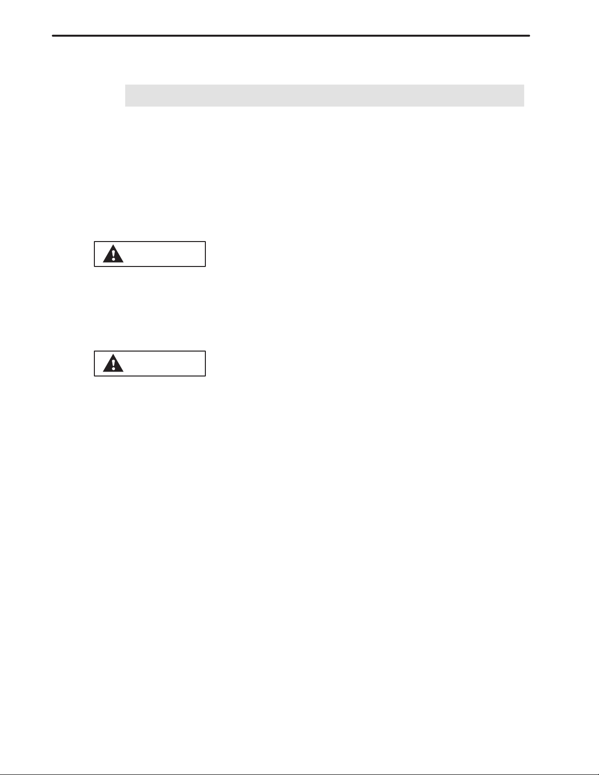
3.1
CREATING A MACHINING PROGRAM
Press the PRGRM function
button.
NC-format programming input
menu
GENERAL
3. FLOWCHART FROM CREATING
A PROGRAM TO EXECUTING IT
Select the conversational mode.
Main menu
Program input menu
(initial settings)
Program input menu (process data)
Program input menu
(figure data)
[FIGURE END]
To select the conversational mode, press the conversational key on the
machine operator’s panel or press the [CAP-I] soft key after entering the
EDIT mode.
Press the [1] soft key to create a new machining program on the main menu.
Enter necessary data, such as the number and name of a machining program, the material of tools used in common in machining programs, and
blank figures.
Moving the cursor forward automatically creates processes.
Select entries for necessary items, such as the type of machining and the
area to be machined. The tools and cutting conditions used for the machining are then automatically determined.
Following the operation guidance on the screen, specify a contour figure.
Press the [PLOT] soft key, if necessary, to display and check the contour
figures previously entered for other processes.
After specifying all necessary figures, press the [FIGURE END] soft key.
After specifying all necessary processes, press the [PRGRM END] soft key.
[PRGRM END]
7
Page 23
3. FLOWCHART FROM CREATING
A PROGRAM TO EXECUTING IT
3.2
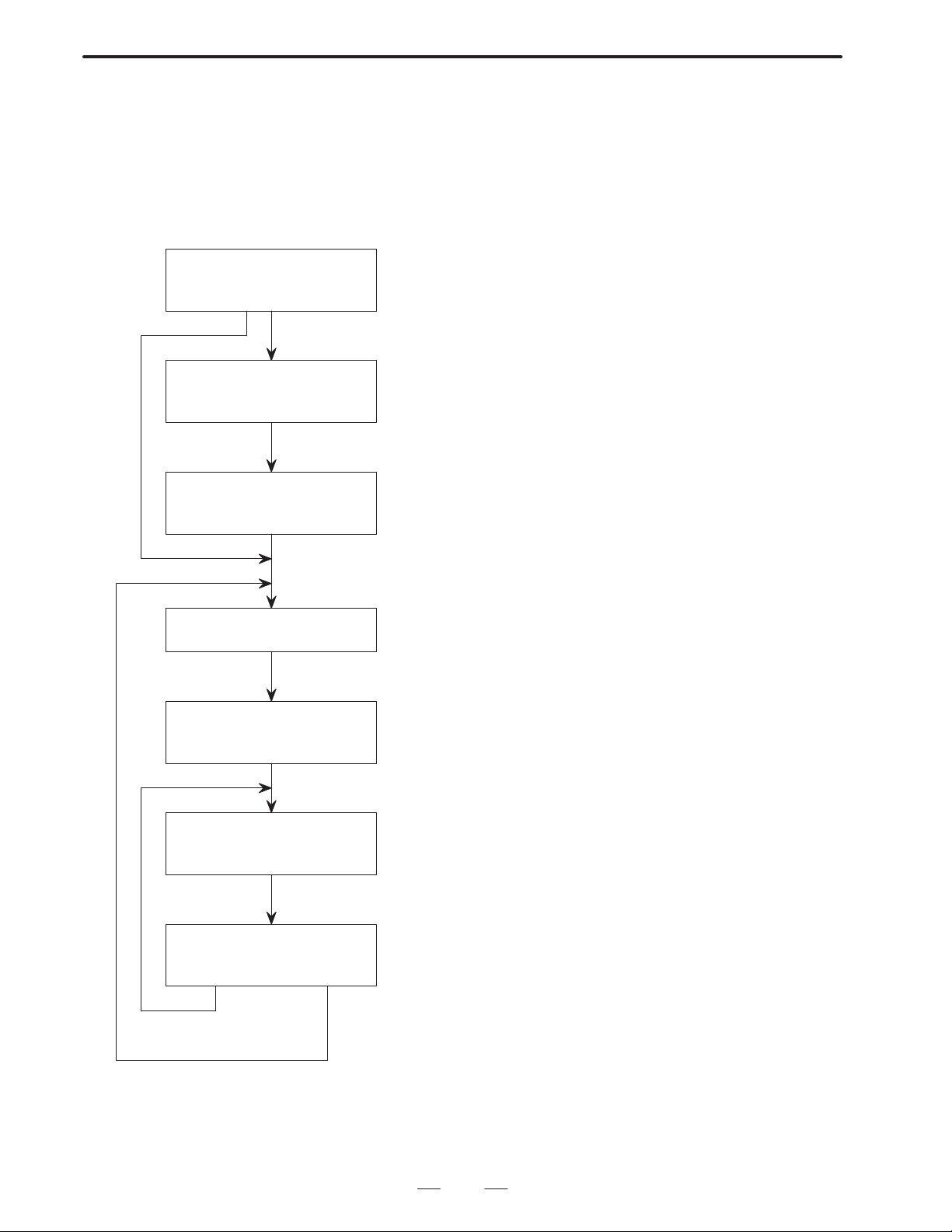
CHECKING A MACHINING PROGRAM
Press the PRGRM function button.
NC-format programming input
menu
GENERAL
B–62444E–1/04
Select the conversational mode.
Main menu
Registered-program directory
screen
Program screen
Page key
To select the conversational mode, either press the conversational key on
the machine operator’s panel or enter the EDIT mode and press the [CAP-I]
soft key.
Press the [2] soft key for creating a new machining program on the main
menu.
Move the cursor to the program to be edited. Press the [EDIT] soft key.
If the program does not fit on one page, press the page key to scroll the
screen.
Pressing the leftmost soft key [ ] returns to the main menu.
[ ]
8
Page 24
B–62444E–1/04
3.3
SELECTING A MACHINING PROGRAM TO BE EXECUTED
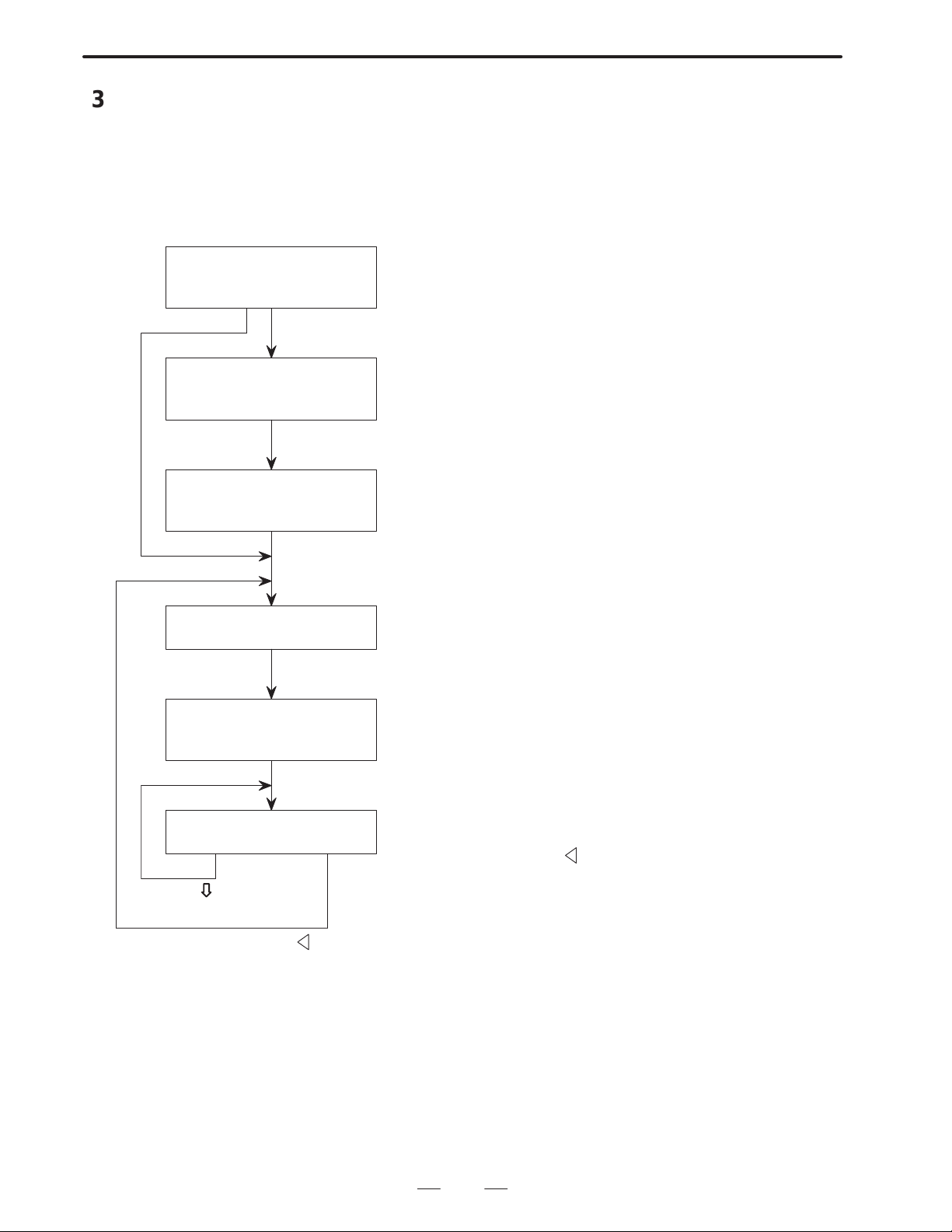
Press the PRGRM function button.
NC-format programming input menu
GENERAL
3. FLOWCHART FROM CREATING
A PROGRAM TO EXECUTING IT
Select the conversational mode.
Main menu
Registered-program directory
screen
Setting screen before execution
To select the conversational mode, press the conversational key on the
machine operator’s panel or enter the EDIT mode and press the [CAP-I] soft
key.
Select the automatic operation mode on the machine operator’s mode.
Press the [4] soft key to operate a conversational machining program direct-
ly after entering the MEM mode on the main menu.
[PRE-EX]: Press this key to specify a chuck barrier, workpiece shift, and
position where the tool is changed (tool change position).
[EXEC]: Press this key to select a machining program to be executed
only when the power is turned on or when a new program is
selected.
On the setting screen before execution, specify the chuck barrier, workpiece
shift, and tool change position. This operation is required only once for each
machining program.
Program screen
Program execution screen
End of execution
When another machining program is selected
Check that the selected machining program is correct, then start automatic
operation.
While the machining program created conversationally is being executed,
the program execution screen is displayed.
9
Page 25

4. SELECTING THE MENU AND
INPUTTING DA TA
SELECTING THE MENU AND INPUTTING DATA
4
GENERAL
Whenever you are uncertain of the operation to be performed next, check
relevant part of this manual. Alternatively, press the [GUIDE] soft key
to display the operation guidance screen for the current operation.
When the screen selected on the conversational main menu is displayed
and you are at a loss what to do next, press the leftmost soft key [
main menu then appears on the screen and you can start from the
beginning.
B–62444E–1/04
]. The
10
Page 26

B–62444E–1/04
GENERAL
4. SELECTING THE MENU
AND INPUTTING DATA
4.1
SOFT KEYS
Example
Example
Soft keys displayed on the conversational screens have different colors
depending on their functions as follows:
(1) Green soft keys
Used mainly for displaying other screens.
[MCHN–C] : Displaying the cutting condition data screen
[TOOL–D] : Displaying the registered tool directory screen
[DETAIL DATA] : Displaying process data not shown on the
machining program screen
[GUIDE] : Displaying operation guidance
(2) Yellow soft keys
Used for selecting the menus.
[1 BAR] : Selecting the type of machining
[1 O–END] : Selecting the area to be machined
[↑↓] : Selecting a figure pattern
(3) Purple soft keys
Used for editing.
Example
[DELETE] : Deleting a process or figure
[INSERT] : Inserting a process or figure
[COPY] : Copying a program or process
When the [+] soft key appears at the right end of the screen, there are soft
keys other than those displayed on the current screen. Press the [+] soft
key to display the other soft keys, if necessary.
The leftmost soft key [<], which is called the super return key , is used to
return from a conversational screen to the main menu.
11
Page 27
4. SELECTING THE MENU AND
INPUTTING DA TA
GENERAL
B–62444E–1/04
4.2
CALCULATION
FUNCTIONS SIMILAR
TO THOSE OF A
HAND–HELD
CALCULATOR
4.2.1
Operation for Calculation
· Addition 100. +200. INPUT
· Subtraction 200. –100. INPUT
· Multiplication 100.
· Division 200. /10. INPUT
20. INPUT
*
Data can be entered for items on the conversational programming menus
(except for the detailed data screen) while calculation is performed on the
same menu.
The four arithmetic functions, addition, subtraction, multiplication, and
division, operate on two numbers. By substituting the result as one term
at the next calculation, calculation can be iterated indefinitely.
Data to be entered for an item must conform to the type of data in the item.
If data contains a component less than the minimum input limit, the
component is ignored.
The following shows key operations for each function.
The result reads at the location where input
keys are displayed.
Example of operation)
12
0 6
.
210.0–65.3
DELETE WINDOW
(INPUT key) ↓
INSERT FIGURE PROCES
To enter the calculated result for the desired item, press the INPUT key
again after checking the result.
Pressing the CAN key deletes characters successively in the input field
from the last character entered.
Key input operation and input key display when the following expression
is calculated:
210. – 65.3 + 1.25
.
–
5 3 INPUT 1
START POINT X
ON/OFF
EDIT
+ 2.5
MCHN–C TOOL–D DETAIL
DATA
INPUT INPUT
PLOT GUIDE
144.7
DELETE WINDOW
INSERT FIGURE PROCES
ON/OFF
START POINT X
MCHN–C TOOL–D DETAIL
EDIT
12
PLOT GUIDE
DATA
Page 28
B–62444E–1/04
GENERAL
Second key operation for the calculation ↓
4. SELECTING THE MENU
AND INPUTTING DATA
144.7+1.25
DELETE WINDOW
INSERT FIGURE PROCES
ON/OFF
(INPUT key) ↓
145.95
DELETE WINDOW
INSERT FIGURE PROCES
ON/OFF
(INPUT key) ↓
The result, 145.95, is entered for the item START POINT X. The cursor
automatically proceeds to the next data item.
START POINT X
MCHN–C TOOL–D DETAIL
EDIT
START POINT X
MCHN–C TOOL–D DETAIL
EDIT
PLOT GUIDE
DATA
PLOT GUIDE
DATA
13
Page 29
4. SELECTING THE MENU AND
INPUTTING DA TA
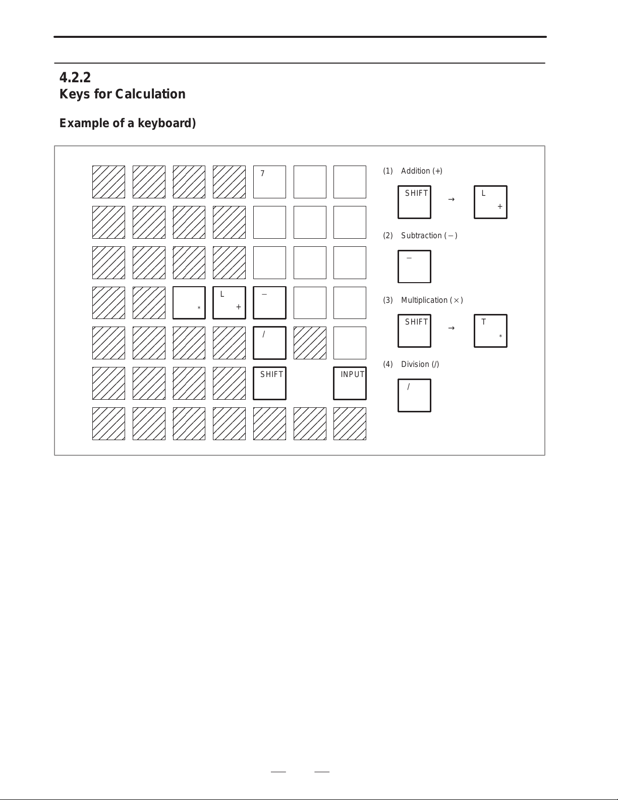
4.2.2
Keys for Calculation
GENERAL
B–62444E–1/04
Example of a keyboard)
T
For the 10″ LCD
L
*
7 8 9
4 5 6
1 2 3
+
/
SHIFT INPUT
0 .
CAN
(1) Addition (+)
SHIFT
(2) Subtraction ()
(3) Multiplication ()
SHIFT
(4) Division (/)
/
→
→
L
+
T
*
14
Page 30
B–62444E–1/04
5
5. HIERARCHY OF THE
GENERAL
CONVERSA TIONAL SCREENS
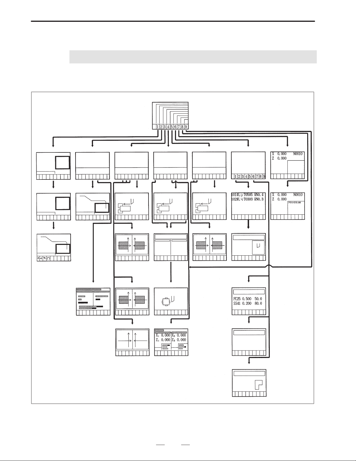
HIERARCHY OF THE CONVERSATIONAL SCREENS
Main menu
Creating programs
PROGRAM
NO
Selecting processes Program screen
TYPE OF
MACHINING
=
Inputting figures Animated simulation
Editing programs
PROGRAM LIST
FOR EDITING
Editing processes
Machining simulation
PROGRAM LIST
FOR
SIMULATION
Setting
before execution
Chuck
barrier
Animated simulation
plus path drawing
Direct operation
PROGRAM LIST
FOR DIRECT
OPERATION
Setting
before execution
Chuck
barrier
T ooling data
Measuring tool offset Cutting condition data
Converting NC programs
PROGRAM LIST
FOR CONVERTING
NC PROGRAMS
Setting
before execution
Chuck
barrier
Animated simulation
plus path drawing
Tool/cutting condition data
TOOL DA TA
MENU
T ool list
Tool data file
T ool of fset
Editting NC programs
Path drawing Position screen
15
Pre-tool list
FINAL TOOL
PRE-TOOL
Chuck/tail stock data
Page 31

II. OPERATION
Page 32

B–62444E–1/04
1
OPERATION
OVERVIEW OF THE PROCEDURE
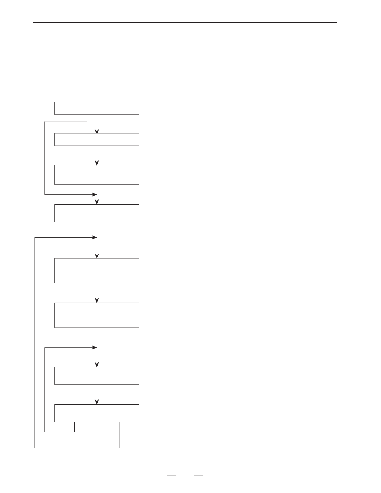
The following shows the general procedure from creating a machining
program to executing it using Super CAP for the F ANUC Series 16–TB.
1. OVERVIEW OF THE PROCEDURE
Reference
Setting parameters
Setting cutting condition data
Setting a pre-tool list when drilling is included
Setting the figures of a chuck and tail stock
Setting a tool data file
Creating a machining program
Selecting a machining program
APPENDIX
II.13 SETTING DATA
II.13 SETTING DATA
II.13 SETTING DATA
II.13 SETTING DATA
II.6 CREATING MACHINING PROGRAMS
II.12 EXECUTING MACHINING PROGRAMS
Mounting tools (and referring to the tooling data)
II.12 EXECUTING MACHINING PROGRAMS
19
Page 33

1. OVERVIEW OF THE PROCEDURE
OPERATION
B–62444E–1/04
Measuring the tool offset
Specifying a tool change position
Setting data before execution
Checking the machining program with the check drawing
Trial machining
Specifying tool wear compensation
II.12 EXECUTING MACHINING PROGRAMS
II.12 EXECUTING MACHINING PROGRAMS
II.12 EXECUTING MACHINING PROGRAMS
II.8 CHECKING MACHINING PROGRAMS
Actual machining
20
Page 34

B–62444E–1/04
2
OPERATION
DESCRIPTION OF THE KEYBOARD
2. DESCRIPTION OF THE KEYBOARD
21
Page 35

2. DESCRIPTION OF THE KEYBOARD
OPERATION
B–62444E–1/04
2.1
KEYBOARD TYPES
FANUC Serlee 16–T
POWER
The CRT/MDI panel consists of a display unit, such as a color 14″ CRT
or color 9.5″ LCD, and a keyboard.
(1) CRT/MDI panel with the 14″ color CRT
Address/numerical key
RESET key
RESET
O
N
(
X
Z
A
U
W
.
M
S
#
I
K
[
8
7
²
5
4
¼
2
1
0
–
EOB
/
POS
PROG
SYSTEM
MESSAGE
↑
PAGE
←
PAGE
↓
)
B
J
=
]
°9½
m
±
G
C
R
OFFSET
SETTING
GRAPH
H
T
³
6
3
.
CAN
↑
↓
HELP key
HELP
P
E
Q
Y
D
?
V
,
L
*
+
F
SP
&
SHIFT
ALTER
INSERT
DELETE
INPUT
CUSTOM
→
SHIFT key
Program edit key
INPUT key
Cancel (CAN) key
Function key
Cursor move key
POWER
FANUC Serles 16–T
Page change keySoft keyPower ON/OFF button
(2) CRT/MDI panel with the 9.5″ color LCD
Function key
Address/numerical key
O
N
G
W
S
PROG
MESSAGE
P
)
E
Q
Z
C
Y
B
D
?
H
V
J
,
L
T
=
*
+
K
R
F
SP
]
&
OFFSET
CUSTOM
SETTING
GRAPH
↑
←
→
↓
X
M
SYSTEM
PAGE
PAGE
(
A
U
.
#
I
[
POS
↑
↓
°9½
7
8
²
³
m
5
4
6
±
¼
2
1
3
0
–
EOB.CAN
/
INPUT
SHIFT
DELETE
INSERT
ALTER
HELP
RESET
Cancel (CAN) key
SHIFT key
INPUT key
HELP key
RESET key
Power ON/OFF button
Soft key
Page change key
22
Program edit key
Cursor move key
Page 36

B–62444E–1/04
OPERATION
2. DESCRIPTION OF THE KEYBOARD
2.2
DETAILS OF THE
KEYBOARD
The keys mainly used for the conversational automatic programming
function are explained here. For other keys that are not dealt with in this
manual, refer to the relevant operator’s manuals.
When the conversational automatic programming function is used, the
operator sometimes has to perform certain operations manually from the
machine operator’s panel. There may include reference position return
operation and turret turning operation (tool replacement). The operator’s
panel varies depending on the machine tool builders and the individual
machines. For the use of the operator’s panel, refer to the appropriate
manual provided by the machine tool builder.
Key Description
Function buttons
POS
PROG
Displays the ACUTUAL POSITION.
When a machining program is created or edited using the
conversational automatic programming function, press this
button first.
When a machining program created using the conversational programming function is being executed, this button
is also used to display the conversational automatic program execution screen that shows the program, current
position, and actual speed.
When the conversational programming screen is displayed,
enter the EDIT mode and press the [END] soft key to display
the NC–format programming screen.
To return from the NC–format programming screen to the
conversational programming screen, press the [CAP–I] soft
key or press the Conversation key on the machine operator’s panel.
OFFSET
SETTING
SYSTEM
MESSAGE
GRAPH
Sets and displays tool offset data, workpiece shift, and custom macro variables.
Pressing this function button twice displays the screen used
for setting and displaying tool data files and cutting condition
data.
Sets and displays parameters, and displays diagnostic
data. Parameter 9000 and subsequent parameters are
used for the conversational automatic programming function.
Displays an alarm number, and displays and sets the state
of the software operator’s panel (only when the appropriate
option is provided).
When a machining program created using the conversational automatic programming function is executed, if an error occurs in the program, some alarms from 3000 to 3099
are issued and indicated.
Displays the machining simulation screen. The conversational function supports a special function that displays the
machining simulation screen, eliminating the need to press
this key.
23
Page 37

2. DESCRIPTION OF THE KEYBOARD
OPERATION
Key Description
Data input key
B–62444E–1/04
Address keys
(alphabetical
keys)
Used to enter alphabetic characters and symbols on the
NC–format programming screen.
In the conversational automatic programming function,
these keys are used only when the name of a machining
program is entered. They are not used on the other program
input screens.
Numeric keys Used when numeric data is entered. In the conversational
automatic programming function, the numeric keys are
used whenever machining programs are created and
edited, and tool data and cutting condition data are entered.
Program edit keys
ALTER
On the ordinary NC–format programming screen, this key
rewrites word address data consisting of an address and
numeric data.
INPUT
On the ordinary NC–format programming screen, this key
inserts word address data consisting of an address and numeric data.
DELETE
On the ordinary NC–format programming screen, this key
deletes word address data consisting of an address and nu-
meric data.
Arrow keys
Cursor keys ↓ : Moves the cursor forward for each setting on the con-
versational programming screen, cutting condition data
setting screen, tool data file setting screen, and so forth.
↑ : Moves the cursor backward for each setting on the
screens mentioned above.
Page keys
ã : Displays the next page when the conversational pro-
gramming screen, cutting condition data setting
PAGE
PAGE
screen, tool data file setting screen, or an other screen
is displayed.
â : Displays the previous page when the one of the
screens mentioned above is displayed.
Soft keys
Leftmost soft key When a function is activated by a certain soft key in a mode
other than the conversational mode, this key returns to the
previous state (the state immediately before the function
button was pressed).
On a screen displayed by the conversational function,
pressing this soft key causes processing to return to the
main menu screen of the conversational function.
Rightmost soft
key
When there are soft keys other than those displayed on the
screen, pressing this soft key displays the next set of soft
keys.
Other soft keys Various functions are assigned according to the applica-
tions. The function assigned to each soft key is indicated at
the bottom of the CRT or LCD.
24
Page 38

B–62444E–1/04
OPERATION
2. DESCRIPTION OF THE KEYBOARD
Key Description
Other keys
Reset key
RESET
Input key
INPUT
Cancel (CAN) key
CAN
Resets the NC to release an alarm.
This key can also be used to stop automatic operation of the
machine or machining simulation.
Sets data entered into the key input buffer in an appropriate
data area.
Deletes one character at a time from numeric or character
data stored in the key input buffer.
Pressing the cancel key then the input key on the conversational programming screen deletes the input data.
25
Page 39

3. OPERA TION MODES
OPERATION MODES
3
OPERATION
B–62444E–1/04
Before performing the desired operation listed below, enter the
corresponding mode.
In the following table, an asterisk (*) in the mode column indicates that
the corresponding operation can be performed in any mode.
Operation Reference Mode
Switching from the NC-format programming
screen to the conversational programming
screen
The screen can be changed in any mode
when the Conversation switch in the machine
operator’s panel is used.
Creating a machining program II. 6 *
Checking input figures for a machining pro-
gram
Checking a machining program using the ani-
mated simulation
Editing a machining program II. 8 *
Outputting a machining program II. 9 EDIT
Reading a machining program II. 10 EDIT
Converting a machining program to the NC-
format program
Selecting a machining program to be
executed
Specifying a chuck barrier on the setting
screen before execution
II. 6 EDIT
II. 7 *
II. 7 MEM
II. 11 MEM
II. 12 *
II. 12 JOG/HANDLE
Specifying a tool changing position on the setting screen before execution
Executing a machining program II. 12 MEM
Setting tool data, cutting condition data, sur-
face roughness data, pre-tool list, chuck/tail
stock figure data
Outputting tool data, cutting condition data,
surface roughness data, pre-tool list, chuck/
tail stock figure data
Reading tool data, cutting condition data, surface roughness data, pre-tool list, chuck/tail
stock figure data
26
II. 12 JOG/HANDLE
II. 13 *
II. 13 EDIT
II. 13 Emergency-stop
Page 40

B–62444E–1/04
OPERATION
Operation ModeReference
3. OPERA TION MODES
Punching and reading the data by using the
batch data input/output function
Measuring tool length offset on the tooling
screen
Entering offset on the tooling screen II. 13 *
Setting parameters APPEN-
II. 14 EDIT
II. 13 JOG/HANDLE
MDI
DIX
27
Page 41

4. TYPES OF SCREENS
TYPES OF SCREENS
4
OPERATION
The screens displayed by the conversational automatic programming
function are shown below. For details of data and operation on each
screen, see the related explanation in this manual.
B–62444E–1/04
28
Page 42

B–62444E–1/04
OPERATION
4. TYPES OF SCREENS
4.1
ONE–PATH LATHES
(1) Parameter setting screen (For details, see Part V, APPENDIX.)
General data relating to the conversational automatic programming
function is set and displayed on this screen.
ACTUAL POSITION
(ABSOLUTE)
F 0
O0001 P0000
MM/M
X 0.000
Z 0.000
C 0.000
Y 0.000
(MODAL)
G00 G25 G13.1 F M
G97 G22 S
G69 G80 SRPM 0
G99 G67 SSPM 0 T
G21 G54 SMAX 32767
G40 G18 SACT 0
<
ABB
REL ALL NO.SRH OFF:0 INPUTON:1
(2) Main menu (For details, see II.6.)
All operations start from this menu.
PARAMETER(CAP BIT PARAM)
9770 NM7 NM3 NM2 NM1 NM0
00000000
9771 1SP 2SP 96S 96M CS2CLD DM2T99
10001001
9772 INO DIO RFN YMD RLFEDM MSOCM5
11100000
9773 MDL GTL TCD RPT OPO GROSG3
01101010
9774 AUT GPW T00 M10 280MLT MLSTLC
11011001
>_
MDI **** *** *** 14:04:09
+INPUT
–
FANUC Super CAP T Ver. Z3.0 [CAP.]
PREP A NEW PROCESS PROGRAM
EDIT THE PROCESSING PROGRAM
PROCESSING SIMULATION
DIRECT OPERATION OF CAP PROGRAM
CONVERT TO NC PROGRAM
TOOL,CUTTING CONDITION DATA
TOOL OFFSET DATA
EDIT NC PROGRAM
EKIT
MODE
END
12 34 5678
MEM
MODE
MEM
MODE
MEM
MODE
14:04:48 MEM
POSIION
9
+
29
Page 43

4. TYPES OF SCREENS
OPERATION
B–62444E–1/04
(3) Machining condition screen (For details, see II.13.)
Cutting condition data for the conversational automatic
programming function is set and displayed on this screen. The
cutting condition data for all possible combinations of tools and
materials to be machined in conversational automatic programming
can be set and displayed.
[CAP.]
101 OUTER T0101 RN 0.400 AC 110 AN 50 TL 20.000
601 DRILL (F) T0303 DD 20.000 AC 150 TL 150.000
651 TAP (F) T0606 DD 18.000 PT 1.500 TL 60.000
*** MACHINING CONDITION (GENERAL) ***
ROUGHING FINISHING
CARBID BITE CARBID BITE
MATERIALFEED/REV. CUT SPD. CUT DPTH MATERIALFEED/REV. CUT SPD.
(MM/REV.) (M/MIN.) (MM) (MM.REV.) (M/MIN.)
FC25 0.5000 80.0 4.000 FC25 0.4000 110.0
FCD45 0.6000 60.0 3.500 FCD45 0.5000 100.0
SS41 0.6000 55.0 5.000 SS41 0.5000 120.0
S45C 0.3000 80.0 8.000 S45C 0.4000 110.0
SKD11 0.5000 80.0 2.000 SKD11 0.2200 150.0
SUS304 0.5000 60.0 2.000 SUS304 0.3000 200.0
AL 0.3000 50.0 3.000 AL 0.3000 120.0
0.0000 0.0 0.000 0.0000 0.0
SET FEEDRATE AMOUNT BY MAX. VALUE
<
WORK
MATERL
MENU
RETURN
(4) Pre–tool list screen (For details, see II.13.)
Final tool and pre–tool data required by the conversational
automatic programming function to automatically determine a
pre–tool for final drilling are set and displayed on this screen.
[CAP.]
101 OUTER T0101 RN 0.400 AC 110 AN 50 TL 20.000
601 DRILL (F) T0303 DD 20.000 AC 150 TL 150.000
651 TAP (F) T0606 DD 18.000 PT 1.500 TL 60.000
*** PRE–TOOL LIST *** NO.01
TOOL NO. TL NAME NOMINL–D
LAST TL S51 TAP (F) 18.000
PRE–TOOL 1 701 CENTER (F) 2.000
2 601 DRIL (F) 20.000
3
4
5
<
SEARCH MENU
RETURN
TOOL
LIST
30
Page 44
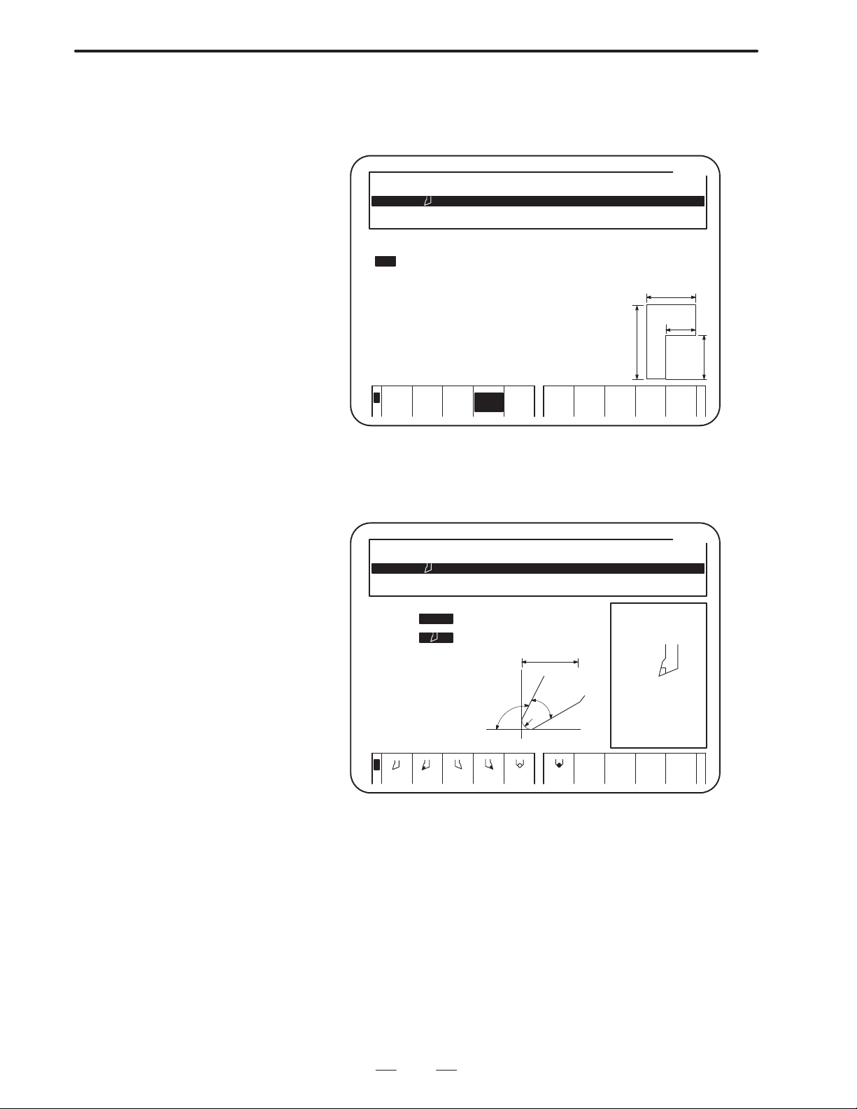
B–62444E–1/04
OPERATION
4. TYPES OF SCREENS
(5) Chuck and tail stock figure data screen (For details, see II.13.)
Data on the chuck and tail stock figures displayed together with the
material figure on the check drawing screen is set and displayed.
[CAP.]
101 OUTER T0101 RN 0.400 AC 110 AN 50 TL 20.000
601 DRILL (F) T0303 DD 20.000 AC 150 TL 150.000
651 TAP (F) T0606 DD 18.000 PT 1.500 TL 60.000
*** CHUCK FIGURE ***
NO.TYPE L W L1 W1
1 EXT 60.0 60.0 30.0 30.0
2
3
4
5
6
7
8
9
10
L
L1
W
W1
<
EXT.
INT.
CHUCK TAIL
STOCK
MENU
RETURN
(6) Screen for setting and displaying tool data (For details, see II.13.)
Up to 99 tool–data items can be set and displayed for all tools
provided (including tools that are not mounted on the turret).
[CAP.]
101 OUTER T0101 RN 0.400 AC 110 AN 50 TL 20.000
601 DRILL (F) T0303 DD 20.000 AC 150 TL 150.000
651 TAO (F) T0606 DD 18.000 PT 1.500 TL 60.000
*** TOOL DATA(1) ***
TOOL–ID NO CN0.101
TOOL TYPE OUTER
TOOL DIREC
ROUGH/FIN OOMMON
OUTPUT T 0101
REVOLUT.–D NORMAL
NOSE–RADIS RN= 0.400
CUTIMG EDG AC= 110
NOSE ANGLE AN= 50
NOSE WIDTH TW= 20.000
IMGNRY NOS TD= 3
TL MATRIAL TM= CARBID
<
AC
TW
AN
MENU
RETURN
TOOL
LIST
TOOL
FIGURE
31
Page 45

4. TYPES OF SCREENS
OPERATION
B–62444E–1/04
(7) Program menu screen (Edit the processing program) (For details, see
II.6.)
This screen appears first when a machining program is created or
edited using the conversational automatic programming function.
The program numbers and names of all machining programs
registered are displayed on this screen.
EDIT THE PROCESSING PROGRAM*** PROGRAM MENU *** [CAP.]
(REST NO. OF PROGRAM 24 PCS.)
(REST NO. OF PROCES 261 PCS.)
PRG.NO. NAME CYCLE TIME CREATED MODIFIED
0001:(EXEC)PRG–11 1M27S 1994/03/24 11:19 1994/03/27 14:02
PROGRAM NO = →SFTKY
INITAL SET FC25 BAR
PROC(01) BAR OUTER END ROUGH T0101
PROC(01) BAR OUTER END FIN T0101
PROC(03) DRILLING (DRILLNG) T0303
PROC(02) END
<
READ DELETE COPY PROCES
ULING
EDIT
EDIT
PLOTSCHED-
GUIDEPUNCH
(8) Program screen (Edit the processing program) (For details, see II.6.)
A machining program consists of a set of machining program units,
called processes. Data necessary for these processes is set and
displayed.
The menu and description of the data item which the cursor points
out are shown on the window in the screen.
EDIT THE PROCESSING PROGRAM [CAP.]
NO. =0001 NAME=PRG–11
INITAL SETMATERIAL SHAPE OUT–DIA IN–DIAWORK–LNG MAX–SCOOLANT
PROC(01) AREA TOOL–NO CUT–SPD FEED/REV CUT–DPTH T–CODE
BAR (R) OUTER END 101 120
PROC(01) AREA ROUGHNES TOOL–NO
BAR (F) OUTER END 5 101
SOFTKE AREA
FC25 BAR 100.000 100.000 2000 ON
FINISHX FINISHZ E–REMOVL
0.100 0.200 2.000
START X= 0.000 Z= 0.000
↑ X= 34.000 Z= 0.000
CHAMFR X= 40.000 Z= 3.000
← X= 40.000 Z= 15.000
ROUND X= 50.000 Z= 20.000
↑ X= 56.000 Z= 20.000
CHAMFR X= 60.971 Z= 21.941
X= 69.402 Z= 38.806
ROUND X= 70.000 Z= 41.232
← X= 70.000 Z= 48.000
1=OUTER END
2=OUTER MID
3=INNER END
4=INNER MID
5=FACE END
4=FACE MID
<
1
OUTER
3
INNER4I–MID5FACING6F–MID
O–MID
32
TOOL
DATA
DETAIL
DATA
PLOT2
+
Page 46

B–62444E–1/04
OPERATION
4. TYPES OF SCREENS
(9) Figure data programming screen (Edit the processing program) (For
details, see II.6.)
Dimension data required for machining is entered and displayed on this
screen. All processes except for the end facing processes consist of the
process data explained previously and the figure data.
The maximum number of figure data items that can be included in each
machining process is given below:
(a) Bar machining: 30
(b) Pattern repeating: 30
(c) Residual machining: 5
(d) End facing: No figure data is needed.
(e) Threading: 5 (for general–purpose threads and metric threads)
(f) Grooving: 5
(g) Necking: 5
(h) Center drilling: 1
(i) Drilling: 1
(j) Tapping: 1
(k) Single action: 30 (Single action II: 104)
(l) M code: 5
(m) C–axis center drilling/drilling/reaming/tapping:
6 (for uneven intervals), even intervals can be specified.
(n) C–axis grooving: 6 (for uneven intervals), even intervals can be
specified.
(o) C–axis notching: 30
(p) C–axis cylindrical machining: 30
(q) Y–axis center drilling/drilling/reaming/tapping: 6 (for uneven
intervals), A hole pattern can be specified.
(r) Y–axis milling: 30
Arbitrary figures formed by arcs and lines can be specified for bar
machining, pattern repeating, C–axis notching, C–axis cylindrical
machining. and Y–axis milling machining. These arbitrary figures are
called contour figures.
By entering dimensional data specified on a drawing, intersections at the
corners of the contour figure can be automatically calculated and the
results are displayed.
Entered data for a contour figure is displayed on the window and the
calculated results are displayed outside the window on the program
screen.
33
Page 47

4. TYPES OF SCREENS
OPERATION
EDIT THE PROCESSING PROGRAM [CAP.]
NO. =0001 NAME=PRG–11
INITAL SETMATERIAL SHAPE OUT–DIA IN–DIAWORK–LNG MAX–SCOOLANT
PROC(01) AREA TOOL–NO CUT–SPD FEED/REV CUT–DPTH T–CODE
BAR (R) OUTEP END 101 120 0.50 5.000 ø101
PROC(01) AREA ROUGHNES TOOL–NO CUT–SPDFEED/REV T–CODE
BAR (F) OUTER END 5 101 150 0.50 ø101
SOFTKE AREA
FC25 BAR 100.000 100.000 2000 ON
FINISHX FINISHZ E–REMOVL
0.100 0.200 2.000
START X= 0.000 Z= 0.000
↑ X= 34.000 Z= 0.000
CHAMFR X= 40.000 Z= 3.000
← X= 40.000 Z= 15.000
ROUND X= 50.000 Z= 20.000
↑ X= 56.000 Z= 20.000
CHAMFR X= 60.971 Z= 21.941
¾ X= 69.402 Z= 38.806
ROUND X= 70.000 Z= 41.232
← X= 70.000 Z= 48.000
COUNT FORM(TAPER LINE)
DIRECTION B= ¾
TAPER END X CORD. X= 70.000
TAPER END Z CORD. Z= 40.000
COMPONENT X I=
COMPONENT Z/ANGLE K/J=
LENGTH Q=
ROUGHNESS(1 10 ) SR= 5
B–62444E–1/04
<
WINDOW
OFF
ALTER ALTER
FIGURE
DELETE MACHIN
COND.
TOOL
DATA
DETAIL
DATA
PLOTINSERT
+
(10) Setting of pre–machining (Processing simulation) (For details, see
II.12.)
Prior to executing the selected machining program, data required for
machining by the program is set on this screen.
PROCESEING SIMULATION *** SETTING OF PRE–MACHING *** [CAP.]
BASIS T–CODE T=
FACE POSITION CZ= 2.000
W–SHIFT SZ=
CHUCK ID NO. C= 1
CHUCK BARRIER X=
TAILSTOCK NO T=
TOOL–CHG POS X=
TO MOVE WORK ORIGIN, PLACE TOOL ON SIDE
BORDER AND PRESS (SET) SOFT KEY
CURRENT W–SHIFT(Z) = 0.000
<
Z=
Z=
W–SHIFT
RETURN
SET TOOLNG
34
Page 48

B–62444E–1/04
OPERATION
4. TYPES OF SCREENS
(11) Tooling data screen (For details, see II.12.)
A list of tool data for the tools used in the currently selected
machining program is displayed on this screen.
*** TOOLING DATA *** [CAP.]
PROCPROCNAMEUSINGTOOLGEOMETRY OFS XGEOMETRY OFS Z RN/WN/DD/TR/TW T–CODE
01 BAR (R) –200.000 –100.000 RN 0.400 0101
01 BAR (F) –200.000 –100.000 RN 0.400 0101
03 DRILLING DRILL –200.000 –100.000 DD 20.000 0303
GEOMETE DFS X
<
Y–AXIS
OFFSET
WEAR
OFFSET
PREPAR TOOL
PAGE 01/01
RETURN
DISPLY
(12) Tool offset measurement screen (Tool preparation) (For details, see
II.12.)
Operation guidance for measuring a tool offset is shown on this
screen. Follow the instructions on the screen to automatically
measure a tool offset.
[CAP.]
101 OUTER T0101 RN 0.400 AC 110 AN 50 TL 20.000
601 DRILL (F) T0303 DD 20.000 AC 150 TL 150.000
651 TAP (F) T0606 DD 18.000 PT 1.500 TL 60.000
*** TOOL PREPARATION *** NO. 101
3.BRING THE TOOL EDGE IN CONTACT WITH X= –200.000
THE SENSOR FROM Z–AXIS DIRECTION Z= –100.000
1
4
<
2
3
PRE–PG RETURN
NXT–PG
35
Page 49

4. TYPES OF SCREENS
OPERATION
B–62444E–1/04
(13) Setting of pre–machining (Processing simulation) (For details, see
II.12.)
Operation guidance for specifying the optimal position at which to
change tools is indicated on this screen. Follow the instructions on
the screen to automatically determine the tool changing position.
PROCESEING SIMULATION *** SETTING OF PRE–MACHING *** [CAP.]
BASIS T–CODE T=
FACE POSITION CZ= 2.000
W–SHIFT SZ=
CHUCK ID NO. C= 1
CHUCK BARRIER X=
TAILSTOCK NO T=
TOOL–CHG POS X=
AFTER CHECKING THAT THERE IS NO
INTERFERENCE,PUSH SOFTKEY [ SET ].
<
Z=
Z=
TOOL–CHB
X
RETURN
SET TOOLNG
(14) Machining simulation screen (For details, see II.7.)
Before the created machining program is executed, it can be checked
with the check drawing screen where the machining operation is
simulated.
00001 P0001
X
X 69.448
Z –38.850
C 0.000
ACT G01
X 0.000
Z 0.000
C 0.000
NXT G01
X 0.160Z
Z –16.939
C 0.000
1M025
500% STOP *** *** 14:13:15 STOP
<
SPEED
UP
DOWN
PLOT
ON/OFF
WORK
AD PROCES SINGLE
PIECE
EXECSPEED
STEP
+
36
Page 50

B–62444E–1/04
OPERATION
4. TYPES OF SCREENS
4.2
TWO–PATH LATHES
In Super CAP T for two–path lathes used with the Series 16–TB, a screen
for tool post 2 is added to each screen explained in Super CAP T for
one–path lathes used with the Series 16–TB.
A screen for tool post 1 is the same as the corresponding screen explained
in Super CAP T for one–path lathes.
(1) Parameter setting screen (For details, see Part V, Appendix.)
Parameters related to the conversational automatic programming
function are common to tool posts 1 and 2 except for parameter No.
9770 specifying allocation of the NC–format program area and
conversational format program area.
ACTUAL POSITION
(ABSOLUTE)
F 0
O0001 P0000
MM/M
X1 0.000
1 0.000
Z
1 0.000
C
1 0.000
Y
(MODAL)
G00 G25 G13.1 F M
G97 G22 S
G69 G80 SRPM 0
G99 G67 SSPM 0 T
G21 G54 SMAX 32767
G40 G18 SACT 0
<
ABB
REL ALL NO.SRH OFF:0ON:1
PARAMETER(CAP BIT PARAM)
9770 NM7 NM3 NM2 NM1 NM0
00000000
9771 1SP 2SP 96S 96M CS2CLD DM2T99
00001001
9772 INO DIO RFN YMD RLFEDM MSOCM5
11100000
9773 MDL GTL TCD RPT OPO GROSG3
01101010
9774 AUT GPW T00 M10 280MLT MLSTLC
11011001
>_
MDI **** *** *** 13:06:58 HEAD1
+INPUT INPUT
–
(2) Main menu (For details, see II.6.)
This menu is common to tool posts 1 and 2.
(3) Machining condition data screen (For details, see II.13.)
This screen is common to tool posts 1 and 2.
37
Page 51

4. TYPES OF SCREENS
OPERATION
B–62444E–1/04
(4) Pre–tool list screen (For details, see II.13.)
Pre–tool list data is specified separately for tool posts 1 and 2. T wo
tool posts are displayed on the screen.
[CAP.:HEAD–L]
101#L OUTER T0101 RN 0.400 AC 110 AN 50 TW 20.000
102#R OUTEP T0101 PN 0.500 AC 90 AN 60 TW 30.000
601#L DRILL (F) T0303 DD 20.000 AC 150 TL 150.000
*** PRE–TOOL LIST *** NO.01
TOOL NO. TL NAME NOMINL–D
LAST TL 651#L TAP (F) 18.000
PRE–TOOL 1 701#L CENTER (F) 2.000
2 601#L DRIL (F) 20.000
3
4
5
<
SEARCH MENU
RETURN
TOOL
LIST
(5) Chuck and tail stock figure data screen (For details, see II.13.)
The data is common to tool posts 1 and 2.
(6) Screen for setting and displaying tool data (For details, see II.13.)
Tool data is specified separately for tool posts 1 and 2. The item
which specifies a tool post is added on the screen.
[CAP.:HEAD–L]
101#L OUTER T0101 RN 0.400 AC 110 AN 50 TW 20.000
102#R OUTER T0101 PN 0.500 AC 90 AN 60 TW 30.000
601#L DRILL (F) T0303 DD 20.000 AC 150 TL 150.000
*** TOOL DATA(1) ***
TOOL–ID NO CN0.101
TOOL TYPE OUTER (HEAD–L)
TOOL DIREC
ROUGH/FIN COMMON
OUTPUT T 0101
REVOLUT.–D NORMAL
NOSE–RADIS RN= 0.400
CUTIMG EDG AC= 110
NOSE ANGLE AN= 50
NOSE WIDTH TW= 20.000
IMGNRY NOS TD= 3
TL MATRIAL TM= CARBID
AC
TW
AN
RN
<
HEAD–L
HEAD–F
38
MENU
RETURN
TOOL
LIST
TOOL
FIGURE
Page 52

B–62444E–1/04
OPERATION
4. TYPES OF SCREENS
(7) Program menu screen (Edit the processing program) (For details, see
II.6.)
A machining program is used in common by both tool posts 1 and
2. This screen is also common for the two tool posts.
(8) Program screen (Edit the processing program) (For details, see II.6.)
One machining program is used in common by both tool posts 1 and
2. The item which specifies whether each process is performed with
tool post 1 or 2 is added on the screen.
EDIT THE PROCESSING PROGRAM [CAP.:HEAD–L]
NO. =0001 NAME=PRG–11
INITAL SET MATERIAL SHAPE OUT–DIA IN–DIA WORK–LNG MAX–S COOLANT
PROC(01) AREA HEAD TOOL–NO CUT–SPD FEED/REV CUT–DPTH T–CODE
BAR (R) OUTER END HEAD–L 101 120 0.50 5.000 0101
PROC(01) AREA HEAD ROUGHNES TOOL–NO CUT–SPD FEED/REV T–CODE
BAR (F) OUTER END –EAD–L 5 101 150 0.50 0101
SOFTKE TURRET_BE_OT
FC25 BAR 100.000 100.000 2000 ON
FINISHX FINISHZE–REMOVLPROD–LNG
0.100 0.200 2.000 96.000
START X= 0.000 Z= 0.000
↑ X= 34.000 Z= 0.000 SR= 5
CHAMFR X= 40.000 Z= 3.000 SR= 5
← X= 40.000 Z= 15.000 SR= 5
ROUND X= 50.000 Z= 20.000 R= 5.000 SR= 5
↑ X= 66.000 Z= 20.000 SR= 5
CHAMFR X= 70.971 Z= 21.941 SR= 5
X= 79.402 Z= 38.806 SR= 5
ROUND X= 80.000 Z= 41.232 R= 1.000 SR= 5
← X= 80.000 Z= 48.000 SR= 5
<
HEAD–L
PRGRM
END
WINDOW
OFF
PROCES
EDIT
MACHIN
COND.
TOOL
DATA
DETAIL
DATA
PLOTHEAD–R
+
(9) Setting of pre–machining (Processing simulation) (For details, see
II.12.)
To specify items concerning setting up tools for each tool post, the
setting menus for both tool posts appear on the screen at the same
time.
PROCESSING SIMULATION *** SETTING OF PRE–MACHING ** [CAP.:HEAD–L]
HEAD–L HEAD–R
BASIS T–CODE T= BASIS T–CODE T=
FACE POSITION CZ= 2.000
W–SHIFT SZ= W–SHIFT SZ=
CHUCK ID NO. C= 1
CHUCK BARRIER X=
TAILSTOCK NO T=
TOOL–CHG POS X= TOOL–CHG POS X=
TO MOVE WORK ORIGIN, PLACE TOOL ON SIDE
BORDER AND PRESS (SET) SOFT KEY
CURRENT W–SHIFT(Z) = 0.000
<
Z=
Z= Z=
W–SHIFT
RETURN
SET HEAD–R TOOLNG
39
Page 53

4. TYPES OF SCREENS
OPERATION
B–62444E–1/04
(10) Tooling data screen (For details, see II.12.)
Different tools are used for each tool post. The tooling data menus
for both tool posts appear on the screen at the same time.
*** HEAD–L TOOLING DATA *** [CAP.:HEAD–L]
PROCPROCNAMEUSINGTOOLGEMOETRY OFS XGEOMETRY OFS Z RN/WN/DD/TR/TW T–CODE
01 BAR (R) 0.000 0.000 RN 0.400 0101
01 BAR (F) 0.000 0.000 RN 0.400 0101
03 DRILLING DRILL 0.000 0.000 DD 20.000 0303
GEOMETE DFS X
<
HEAD–L
HEAD–F Y–AXIS
OFFSET
WEAR
OFFSET
PREPAR TOOL
PAGE 01/01
RETURN
DISPLY
(11) Tool offset measurement screen (Tool preparation) (For details, see
II.12.)
Operation guidance for measuring tool offsets is indicated for each
tool post.
[CAP.:HEAD–L]
101#L OUTER T0101 RN 0.400 AC 110 AN 50 TW 20.000
102#R OUTER T0101 PN 0.500 AC 90 AN 60 TW 30.000
601#L DRILL (F) T0303 DD 20.000 AC 150 TL 150.000
*** TOOL PREPARATION *** NO. 101
3.BRING THE TOOL EDGE IN CONTACT WITH X= 0.000
THE SENSOR FROM Z–AXIS DIRECTION Z= 0.000
1
4
<
2
3
PRE–PG RETURN
NXT–PG
40
Page 54

B–62444E–1/04
OPERATION
4. TYPES OF SCREENS
(12) Setting of pre–machining screen (Processing simulation) (For
details, see II.12.)
Operation guidance for specifying the optimal position at which to
change tools is indicated for each tool post.
PROCESSING SIMULATION *** SETTING OF PRE–MACING *** [CAP.:HEAD–L]
HEAD–L HEAD–R
BASIS T–CODE T= BASIS T–CODE T=
FACE POSITION CZ= 2.000
W–SHIFT SZ= W–SHIFT SZ=
CHUCK ID NO. C= 1
CHUCK BARRIER X=
TAILSTOCK NO T=
TOOL–CHG POS X= TOOL–CHG POS X=
AFTER CHECKING THAT THERE IS NO
INTERFERENCE,PUSH SOFTKEY[SET].
<
Z=
Z= Z=
TOOL–CHB FOB X
RETURN
SET HEAD–R TOOLNG
(13) Machinig simulation for two–tool–post lathes or two–path lathes
with two opposing spindles (For details, see II.7.)
T wo materials are machined separately with tool posts 1 and 2 in the
lathes mentioned above. The states of machining with tool posts are
displayed on the screen at the same time.
HEAD1 HEAD2 00001 P0001
0M00S
31.7
500%
<
SPEED
UP
PLOT PROG
DOWN
X1
X1 0.000
Z1 0.000
C1 0.000
ACT G00
X 0.000
Z 0.000
C 0.000
NXT G00
X 0.000
Z 0.000
C 0.000
X2
Z2
0M28S
31.7
MEM STOP *** *** 13:13:52 STOP
HEAD PROCES SINGLE
ON/OFF
WORK
PIECE
X2 90.000
Z2 –24.000
C2 0.000
ACT G01
X 0.000
Z 0.000
C 0.000
NXT G01
X 0.000
Z 0.000
C 0.000
EXECSPEED
STEP
+
41
Page 55

4. TYPES OF SCREENS
OPERATION
B–62444E–1/04
(14) Machining simulation for two–tool–post lathes or two–path lathes
with one spindle (For details, see II.7.)
With lathes of these types, a single workpiece is simultaneously
machined with tool posts 1 and 2. The machining status is displayed
on the screen as machining progresses.
HEAD1 HEAD2 00001 P0001
X1 60.000
Z1 –21.528
C1 0.000
ACT G00
X 0.000
Z 0.000
C 0.000
NXT G01
X 4.43
Z 1.7
C 0.000
1M07S
24.4
500%
<
SPEED
UP
PLOT PROG
DOWN
1M17S
MEM STOP *** *** 13:25:40 STOP
HEAD PROCES SINGLE
ON/OFF
WORK
PIECE
X1
X2 90.000
Z2–149.800
C2 0.000
ACT G01
X 0.000
Z 0.000
C 0.000
NXT G01
X 0.000
Z –69.561
C 0.000
EXECSPEED
STEP
+
42
Page 56

B–62444E–1/04
5
OPERATION
DESCRIPTION OF COORDINATE SYSTEMS
The following explains the coordinate systems used in the conversational
automatic programming function.
COORDINA TE SYSTEMS
5. DESCRIPTION OF
43
Page 57

5.DESCRIPTION OF
COORDINATE SYSTEMS
OPERATION
5.1
ONE–PATH LATHES
B–62444E–1/04
5.1.1
Machine Coordinate System
The machine coordinate system is set as follows:
+X
Machine zero point
Tool post
Chuck
Spindle
+Z
The above figure shows the state in which a tool post has returned to the
reference position. The X and Z machine coordinates of the position of
the tool post are 0. When the tool post is manually returned to a reference
position, the X and Z machine coordinates of the machine reference
position are automatically set to 0.
The directions of the X– and Z–axes are specified so that the tool post
moves away from a workpiece or the spindle when the tool post moves
in the positive X and Z directions.
This machine coordinate system is kept unchanged, regardless of whether
the program reference position, explained later, is set on the end face of
a workpiece or the end face of the chuck.
The coordinates in the machine coordinate system are indicated on the
all–position display screen or in the MACHINE column on the
conversational program execution screen. The all position display screen
is displayed by pressing the POS function button, then pressing the [ALL]
soft key.
44
Page 58

B–62444E–1/04
OPERATION
5. DESCRIPTION OF
COORDINA TE SYSTEMS
5.1.2
Workpiece Coordinate System
The machine coordinate system previously mentioned is peculiar to a
specific machine. It is determined uniquely regardless of the workpieces
and tools used.
Another coordinate system is required for each tool to prevent
programmed positions from changing between tools because of the
difference in tool dimensions. This coordinate system must be set with
respect to the dimensions of a specific tool. Such coordinate systems are
called workpiece coordinate systems.
A workpiece coordinate system is determined using the tool geometry
compensation function. For details of tool geometry compensation, refer
to the Series 16/18–TB or Series 16/18–TC Operator’s Manual.
The origin of the workpiece coordinate system may be set on the end face
of either a workpiece or the chuck.
(1) When the origin of the workpiece coordinate system is placed on the
end face of a workpiece
+X
Machine zero point
Chuck
Spindle
Origin of the workpiece
coordinate system
+Z
(2) When the origin of the workpiece coordinate system is place on the
end face of the chuck
+X
Machine zero point
Chuck
Spindle
Origin of the workpiece
coordinate system
+Z
45
Page 59

5. DESCRIPTION OF
COORDINATE SYSTEMS
OPERATION
B–62444E–1/04
5.1.3
Program Coordinate System
When a machining program is created by entering data conversationally ,
the dimensions are specified with respect to the reference position
peculiar to a workpiece. This reference position is called the program
reference position.
The program reference position may be set on the end face of either the
workpiece or the chuck.
Setting parameter No. 9786 (ZEROPT) to 0 places the program reference
position on the end face of the workpiece. Setting the parameter to 1
places the reference position on the end face of the chuck.
(1) When the program reference position is placed on the end face of the
workpiece
+X
Machine zero point
Chuck
Program reference
Spindle
+Z
position
Origin of the workpiece
coordinate system
(2) When the program reference position is placed on the end face of the
chuck
+X
Machine zero point
Chuck
Spindle
Origin of the workpiece
coordinate system, Program reference position
+Z
46
Page 60

B–62444E–1/04
OPERATION
5. DESCRIPTION OF
COORDINA TE SYSTEMS
5.2
TWO–PATH LATHES
WITH TWO
OPPOSING
SPINDLES
5.2.1
Machine Coordinate System
In two–path lathes with two spindles, coordinate systems used for tool
posts 1 and 2 are the same as those for one–path lathes except that the
direction of the Z–axis is opposite in coordinate systems for tool post 2.
The following figure shows the machine coordinate system for tool post
2.
+X2
+Z2
Machine zero point
Tool post 2
Chuck
Spindle
The directions of the X–and Z–axes are specified so that the tool post
moves away from a workpiece or the spindle when the tool post moves
in the positive X and Z directions.
47
Page 61

5. DESCRIPTION OF
COORDINATE SYSTEMS
OPERATION
B–62444E–1/04
5.2.2
Workpiece Coordinate System
In a workpiece coordinate system used for tool post 2, like in the machine
coordinate system for tool post 2, the direction of the Z–axis is opposite
that used for tool post 1.
(1) When the origin of a workpiece coordinate system is placed on the
edge of a workpiece
+X2
Machine zero point
Chuck
+Z2
Spindle
(2) When the origin of a workpiece coordinate system is placed on the
edge of the chuck
+X2
Machine zero point
Chuck
+Z2
Spindle
48
Page 62

B–62444E–1/04
OPERATION
5. DESCRIPTION OF
COORDINA TE SYSTEMS
5.2.3
Program Coordinate System
In a program coordinate system used for tool post 2, like in the machine
coordinate system for tool post 2, the direction of the Z–axis is opposite
that used for tool post 1.
(1) When the program reference position is placed on the edge of a
workpiece
T oll
Machine zero
point
Program reference position
Origin of the workpiece
coordinate system
post 2
+X2
Chuck
Spindle
+Z2
(2) When the program reference position is placed on the edge of the
chuck
Machine zero
point
+Z2
Chuck
Program reference position
Origin of the workpiece
coordinate system
+X2
Spindle
49
Page 63

5. DESCRIPTION OF
COORDINATE SYSTEMS
OPERATION
B–62444E–1/04
5.3
FOR TWO–PATH
LATHES WITH ONE
SPINDLE
5.3.1
Machine Coordinate System
In two–path lathes with one spindle, coordinate systems used for tool
posts 1 and 2 are the same as those for one–path lathes except that the
direction of the X–axis is opposite in coordinate systems for tool post 2.
The following figure shows the machine coordinate system for tool post
2.
Chuck
Spindle
Tool post 2
+Z2
Machine zero point
+X2
50
Page 64

B–62444E–1/04
OPERATION
5. DESCRIPTION OF
COORDINA TE SYSTEMS
5.3.2
Workpiece Coordinate System
In a workpiece coordinate system used for tool post 2, like in the machine
coordinate system for tool post 2, the direction of the X–axis is opposite
that used for tool post 1.
(1) When the origin of a workpiece coordinate system is placed on the
edge of a workpiece
Chuck
Spindle
Origin of the workpiece
coordinate system
+X2
Machine zero point
+Z2
(2) When the origin of a workpiece coordinate system is placed on the
edge of the chuck
Spindle
Chuck
Origin of the workpiece
coordinate system
+X2
+Z2
Machine zero point
51
Page 65

5. DESCRIPTION OF
COORDINATE SYSTEMS
OPERATION
B–62444E–1/04
5.3.3
Program Coordinate System
In a two–path lathe with one spindle and two tool posts, a program
coordinate system used for tool post 2 is the same as that for tool post 1.
(1) When the program reference position is placed on the edge of a
workpiece
+X
Machine zero
point
Spindle
Chuck
+Z
Program reference position
Origin of the workpiece
coordinate system
(2) When the program reference position is placed on the edge of the
chuck
Spindle
Chuck
+X
Origin of the workpiece coordinate
system, program reference position
Machine zero point
+Z
52
Page 66

B–62444E–1/04
6
OPERATION
CREATING MACHINING PROGRAMS
6. CREA TING MACHINING PROGRAMS
53
Page 67

6. CREA TING MACHINING PROGRAMS
OPERATION
B–62444E–1/04
6.1
FORMAT OF
MACHINING
PROGRAM USED
FOR THE ONE–PATH
LATHES
The format of machining programs created using the conversational
automatic programming function is different from that of NC–format
machining programs.
An NC–format machining program consists of NC block instructions in
which G codes, axis–address data, and miscellaneous functions are
combined. An NC block instruction corresponds to an NC operation.
A conversational machining program consists of processes. A process
here refers to a set of machining operations using one tool. The process
contains process data, such as a tool to be used and cutting conditions, and
figure data including the figure of a machined product. NC data necessary
for machining is automatically generated from the process and figure
data.
NC–format machining programs and conversational machining
programs are stored separately as shown below.
Part program
storage
Conversational
machining
programs
A program is stored by each process block
(it corresponds to a tape length of about
0.76 m, 30 inches).
NC–format
machining
programs
A program is stored by each character (it
corresponds to a tape length of about 2.54
mm, 0.1 inches).
The storage capacity assigned to machining programs is determined
according to the length of the optional tape attached. Setting parameter
No. 9770 (NMEM0 to NMEM4) sets the ratio of the storage capacity used
for NC–format and conversational machining programs.
54
Page 68

B–62444E–1/04
"""""""
OPERATION
6. CREA TING MACHINING PROGRAMS
6.2
FORMAT OF
MACHINING
PROGRAM USED
FOR THE TWO–PATH
LATHES
Conversational machining
program
Process 1: Machining the
outer surface of
a bar with tool
post 1
Process 2: Grooving on an
outer surface
with tool post 1
Process 3: Threading on an
outer surface
with tool post 1
Process 4: Machining the
end face of a
bar with tool
post 2
Process 5: Drilling with tool
post 2
Process 6: Tapping with
tool post 2
In the Two–path lathes, an NC–format machining program is created
separately for each tool post, tool post 1 or 2, and is stored. Each
NC–format machining program is totally independent.
In a conversational machining program, each machining process is
created separately for tool post 1 or 2. However, processes for both tool
posts are combined and stored as a one machining program. When a
certain conversational machining program is selected, a workpiece is
machined within the processes specified in the program for tool posts 1
and 2. Different machining programs cannot be executed for the two tool
posts.
The following figure shows how a conversational machining program is
executed.
Processes to be executed
with tool post 1
The processes
are classified
by the tool post
used.
Process 1: Machining the
Process 2: Grooving on an
Process 3: Threading on an
Processes to be executed
with tool post 2
Process 4: Machining the
Process 5: Drilling
Process 6: Tapping
outer surface of
a bar
outer surface
outer surface
end face of a
bar
Process 6
with a tap
#2
Process 4 with
an end–facing
tool #2
Process 5
with a drill
#2
Workpiece to be
machined
55
Process 2
with a
grooving
tool #1
Process 1
with a tool
used for
machining
an outer
surface
#1
Process
3 with a
threading
tool
#1
Page 69

6. CREA TING MACHINING PROGRAMS
OPERATION
B–62444E–1/04
6.3
SELECTING THE
CONVERSATIONAL
MODE
Select the conversational mode before creating a machining program
using the conversational automatic programming function.
To enter the conversational mode, use the Conversation button on the
machine operator’s panel by referring to the operator’s manual issued by
the machine tool builder or use the [CAP–I] soft key on the program
screen in the NC as follows:
(1) Select the EDIT mode by using the mode switch on the machine
operator’s panel.
(2) Press the PRGRM function button to display the NC–format
program screen.
(3) Press the [CAP–I] soft key to enter the conversational mode. Then
the main menu for the conversational function appears.
FANUC Super CAP
PREP A NEW PROCESS PROGRAM
EDIT
MODE
END
1
EDIT THE PROCESSING PROGRAM
PROCESSING SIMULATION
DIRECT OPERATION OF CAP PROGRAM
CONVERT TO NC PROGRAM
TOOL,CUTTING CONDITION DATA
MEM
MEM
MODE
MEM
MODE
MODE
234 5678
[CAP:HEAD–L]
TOOL OFFSET DATA
EDIT NC PROGRAM
POSIION
14:04:48 MEM
9
+
(4) To return from the conversational input mode to the NC–format
mode in the main menu, change the mode to the EDIT mode and
press the [END] soft key.
NOTE
1 At the top right corner of the screen displayed by the
conversational function, [CAP:HEAD–L]/[CAP:HEAD–R]
(two–path lathe) or [CAP] (one–path lathe) is displayed.
2 At the bottom right corner of the screen, the current time and
current mode are displayed.
56
Page 70

B–62444E–1/04
OPERATION
6. CREA TING MACHINING PROGRAMS
6.4
CREATING A MACHINING PROGRAM
6.4.1
Entering the Number and Name of a Program
Example)
Press the [1] soft key to create a new machining program on the main
menu.
A number and name can be specified for a machining program using the
conversational automatic programming function.
When entering the DEMONSTRATION program with number 210
(1) (PREP A NEW PROCESS PROGRAM)
210
INPUT
DEMONSTRAION
PREP A NEW PROCESSING PROGRAM [CAP.:HEAD–L]
NO. =0210 NAME = DEMONSTRATION
INITAL SET MATERIAL SHAPE OUT–DIA IN–DIA WORK–LNG MAX–S COOLANT
SOFTKE TURRET_BE_OT
FC25 BAR 100.000 145.000 2000 ON
FINISHX FINISHZE–REMOVLPROD–LNG
0.200 0.100 2.000 150.000
INPUT
∼
SOFTKEY MATERIAL
FC25
SS41 S45C SKD11 SUS304 PLOTFCD45
AL<
∼
+
NOTE
1 Up to 20 characters can be used for the name of a program.
2 The PROD–LNG data item is displayed only when the
conversational function for two–turret lathes with two
opposing spindles or lathes with a sub–spindle is used.
3 The displayed workpiece materials vary with the machine
tool builder. For details, refer to the manual supplied by the
machine tool builder.
57
Page 71

6. CREA TING MACHINING PROGRAMS
OPERATION
B–62444E–1/04
6.5
INITIAL SETTINGS
Initial settings are commonly used in a conversational machining
program.
PREP A NEW PROCESS PROGRAM [CAP.:HEAD–L]
NO. =0120 NAME = MSTU
INITAL SET MATERIAL SHAPE OUT–DIA IN–DIA WORK–LNG MAX–S COOLANT
SOFTKE TURRET_BE_OT
∼
SOFTKEY MATERIAL
FC25
FC25 BAR 100.000 145.000 2000 ON
FINISHX FINISHZE–REMOVLPROD–LNG
0.200 0.100 2.000 150.000
SS41 S45C SKD11 SUS304 PLOTFCD45
AL<
∼
+
The data for the machining program created immediately before the
current program is automatically copied to initial setting items.
6.5.1
Details of Settings
MATERIAL (workpiece material) : Material to be machined. A
material is chosen from either eight
or 24 types of materials. When it is
chosen from 24 types, press the [+]
rightmost soft key to display the
ninth and subsequent materials.
Set the workpiece material with the
parameter.
SHAPE (shape of a workpiece) : Figure of the workpiece to be
machined. Choose either a blank
rod or a blank plate.
SHAPE
––– – ––RGH
BAR
BAR:Blank rods or blanks having a rounded portion
RGH SHAPE : Casting or material for casting
–
NOTE
When the workpiece material is changed on the initial
setting screen for an existing machining program, all cutting
condition data in the machining program is automatically
replaced by newly calculated data corresponding to the new
material.
Similarly, when the workpiece figure is changed,
corresponding data in the machining program, such as the
start point for cutting, is calculated again.
58
Page 72
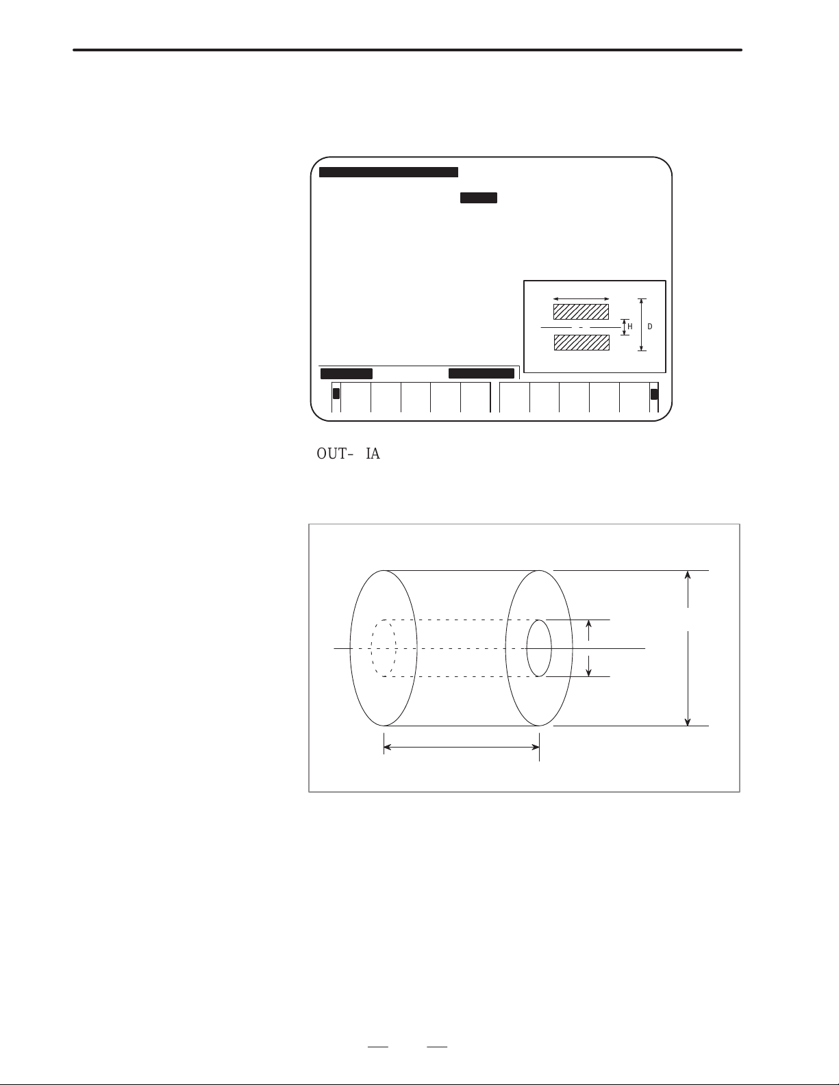
B–62444E–1/04
OPERATION
6. CREA TING MACHINING PROGRAMS
The selection of the workpiece figure, for either blank rods or blank
plates, determines the subordinate input data items for blank dimensions.
(1) When BAR is selected as the workpiece figure
PREP A NEW PROCESS PROGRAM [CAP.:HEAD–L]
NO. =0120 NAME = MSTU
INITAL SET MATERIAL SHAPE OUT–DIA IN–DIA WORK–LNG MAX–S COOLANT
DELETE
FC25 BAR 100.000 145.000 2000 ON
FINISHX FINISHZE–REMOVLPROD–LNG
0.200 0.100 2.000 150.000
L
H
OUTSIDE DIA
PROGRAM
END
WINDOW
ON/OFF
PROCES
EDIT
TOOL–D<
MCHN–C DETAIL
DATA
PLOTINSERT
D
+
OUT–DIA (maximum diameter) : Outer diameter of the blank
IN–DIA (minimum diameter) : Inner diameter of the blank
WORK–LNG : Length of the blank
Outer diameter
of the blank (D)
Inner diameter
of the blank (H)
Length of the blank (L)
59
Page 73

6. CREA TING MACHINING PROGRAMS
(2) When RGH SHAPE is selected as the workpiece figure
To specify the figure of a blank plate, enter the coordinates of up to 12
points for each of the outer and inner surfaces of the figure in the program
coordinate system.
OPERATION
PREP A NEW PROCESS PROGRAM [CAP.:HEAD–L]
NO. =0120 NAME = MSTU
INITAL SET MATERIAL SHAPE OUT–DIA IN–DIA WORK–LNG MAX–S COOLANT
DELETE
FC25RGH SHAPE 100.000 145.000 2000 ON
FINISHX FINISHZE–REMOVLPROD–LNG
0.200 0.100 2.000 150.000
OUTSIDE–PX1 Z1 X2 Z2 X3 Z3
21
3 4
6
5
78
OUTSIDE –PX1
FIGURE
END
WINDOW
ON/OFF
PROCES
EDIT
TOOL–D<
MCHN–C DETAIL
DATA
PLOTINSERT
9 10
11
12
+
B–62444E–1/04
Points on the outer surface
X1 :
Z1 :
∼∼
∼∼
X and Z coordinates of points on the outer
surface in the program coordinate system
X12 :
Z12 :
Points on the inner surface
X1 :
Z1 :
∼∼
∼∼
X and Z coordinates of points on the inner
surface in the program coordinate system
X12 :
Z12 :
NOTE
Enter the coordinates of necessary positions on both the
outer and inner surfaces. Enter coordinates of three points
in a line. When the cursor moves to the next line, new data
items for three points appear.
After data is entered for the necessary points on the outer
surface, press the [FIGURE END] soft key to display the
data items for points on the inner surface.
After data is entered to points on the inner surface, press the
[FIGURE END] soft key.
Pressing the [DELETE] soft key deletes all the data which
is on the line the cursor points out.
Pressing the [INSERT] soft key creates a new data entry line
for three points immediately after the line the cursor points
out.
60
Page 74

B–62444E–1/04
Example) Cross–section of molding material
OPERATION
6. CREA TING MACHINING PROGRAMS
Points on the outer surface
Coordinates of point (1) = (X1, Z1)
Coordinates of point (2) = (X2, Z2)
Coordinates of point (3) = (X3, Z3)
Coordinates of point (4) = (X4, Z4)
Coordinates of point (5) = (X5, Z5)
Coordinates of point (6) = (X6, Z6)
Figure for checking
the outside claw
(1)
(2)
(3)
(10)
(11) (12)
Program reference position (on the edge of the chuck)
(9)
(8)
(4)
(5)
(6)
(7)
Program reference position
(on the edge of a workpiece)
Points on the inner surface
Coordinates of point (7) = (X1, Z1)
Coordinates of point (8) = (X2, Z2)
Coordinates of point (9) = (X3, Z3)
Coordinates of point (10) = (X4, Z4)
Coordinates of point (11) = (X5, Z5)
Coordinates of point (12) = (X6, Z6)
61
Page 75

6. CREA TING MACHINING PROGRAMS
MAX–S (maximum spindle speed) : Maximum spindle speed under
COOLANT : Coolant commonly used in this machining
OPERATION
B–62444E–1/04
constant surface–speed control
program. Select the appropriate coolant using the
following soft keys.
ON
Initial value of coolant data for each processes is automatically determined by this setting.
––– – – ––OFF
–
FINISHING X/Z (finishing allowance X/Z) : Finishing allowance in the
X–axis (diameter) and Z–axis direction
END REMOV AL (end face of a workpiece) : Machining allowance at end
facing
Degree of cutting at
the end face
(such as mill scale)
Program reference position
(on the edge of a workpiece)
Program reference position (on the edge of the chuck)
PROD–LNG (length of a product) : Length of a finished product
End–facing allowance for tool post 2 is obtained by subtracting (end face
of a workpiece) and (length of a product) from (length of a workpiece).
Length of a finished product is effective only when two–path lathes with
two opposing spindles and lathe with subspindles are used.
62
Page 76

B–62444E–1/04
OPERATION
6. CREA TING MACHINING PROGRAMS
WARNING
After you enter or copy the initialization data, make sure that all data is correct.
Material : Select the same material as the actual workpiece from the material
menu. If the desired material is not on the menu, discontinue
machining the workpiece. If an incorrect material is selected, or an
incorrect cutting condition is used, the tool may be damaged, and
even injuries may occur.
Shape, outer blank surface, inner blank surface, blank length,
and molding outside/inside diameter points
: Enter the correct data that matches the actual workpiece. If
incorrect data is entered, the tool may bump against the workpiece,
possibly causing damage to the tool and/or machine, and even
injuries.
Maximum rotation speed : For the machine spindle, workpiece, and workpiece fastening jig, do
not specify data higher than the maximum rotation speed allowed
for them.
Running the machine with incorrect data may allow the workpiece
and/or jig to come off by centrifugal force, possibly causing damage
to the machine, and even injuries.
Coolant : Set coolant selection to ON as required. If it is set to OFF when a
coolant is necessary, the tool may be damaged, and even injuries
may occur.
Finishing allowance X/Z : Enter the finishing allowance data that assures safe finishing work
for cutting. If incorrect data is entered, finishing may result in
damage to the tool, and even injuries.
End–surface allowance : Be sure to enter the same end–surface allowance data as that for
the actual workpiece.
If incorrect data is entered, the tool may bump against the
workpiece, possibly causing damage to the tool and/or machine,
and even injuries.
Product length : For a two–path lathe with two facing spindles or a lathe with a
subspindle, enter the same data as the length of the actual product.
If incorrect data is entered, the tool may bump against the
workpiece, possibly causing damage to the tool and/or machine,
and even injuries.
63
Page 77

6. CREA TING MACHINING PROGRAMS
OPERATION
B–62444E–1/04
6.5.2
Operation for Initial
Settings
PREP A NEW PROCESS PROGRAM [CAP.:HEAD–L]
NO. = 0120 NAME = MSTU
INITAL SET MATERIAL SHAPE OUT–DIA IN–DIA WORK–LNG MAX–S COOLANT
PROC (01)
SOFTKEY MACHINING
(1) Entering or changing data
Press the soft key corresponding to the desired menu. For some
menus, the guidance is shown on the window.
Use the numeric keys and the INPUT key to enter data.
(2) Terminating the initial setting entry
After entering all the necessary data for a certain initial setting, press
the INPUT key or cursor key several times to move the cursor to the
next initial setting line.
Then a new process is created. The following soft key menu for
selecting processes and the window for guidance appear on the
screen.
FC25 BAR 100.000 145.000 2000 ON
FINISHX FINISHZ E–REMOVL PROD–LNG
0.200 0.100 2.000 150.000
1=BAR
2=PT.RPT
3=RESID.
4=FACING
5=THREAD
6=GROOVE
7=NECK
8=CENTER
9=DRILL
10=TAP
1
<
BAR
2
PT.RPT3RESID.
4
FACING5THREAD
64
6
GROOVE7NECK
8
CENTER
9
DRILL10TAP
+
Page 78

B–62444E–1/04
OPERATION
6. CREA TING MACHINING PROGRAMS
6.6
PROCESS DATA SCREEN
A machining program consists of several processes, or units of
machining.
Process data, such as the type of machining, tools to be used, and cutting
conditions, is set and displayed on the process data screen.
Data which must be set in this screen depends on the type of machining
in the process. For details, see Part III, “T ypes of machining programs.”
NOTE
Process data for a two–path lathe contains the process data
for a one–path lathe and the items (units) for selecting a tool
post.
WARNING
No check is made on whether the machining sequence is
correct. For example, even if you program tapping without
preparing a hole, or finishing without roughing, the machine
runs according to the programmed machining sequence.
For this reason, when creating a machining program using a
conversational function, be sure to confirm that the machine
runs in the correct sequence.
If the machining sequence is incorrect, the tool may bump
against the workpiece, or the machine may be forced to
perform unnatural machining, possibly causing damage to the
tool and/or machine, and even injuries.
WARNING
When process data is entered, tool and cutting condition data
is determined automatically according to the selected
machining type and area. Be sure to check that the
automatically determined data is correct.
If the data is incorrect, correct it.
If the tool and cutting condition data is incorrect, the tool may
bump against the workpiece, or the machine may be forced to
perform unnatural machining, possibly causing damage to the
tool and/or machine, and even injuries.
65
Page 79

6. CREA TING MACHINING PROGRAMS
OPERATION
B–62444E–1/04
6.6.1
Operation for the
Process Data Screen
(1) Entering or changing data
Use the soft key to select the menu. Use the numeric keys and
INPUT key to enter data.
(2) Automatic determination of tools to be used and cutting conditions
Tools to be used and cutting conditions are automatically
determined and displayed on the screen by only entering the type of
machining and the area to be machined.
The functions for automatically determining tools and cutting
conditions depend on the type of machining. For details, see Part III,
“Types of machining programs.”
(3) Terminating data input
After all the necessary data is entered on the process data screen,
follow the step below according to the type of machining.
(a) When the type of machining is set to end facing, turning and
drilling, miscellaneous machining, sub–call or M.
After all the necessary data is entered, if data is to be entered for
the next process, move the cursor to the next line with the cursor
key.
This operation creates an empty process. The menu for selecting
a machining type is displayed in the soft key field.
T o return to the main menu screen once program creation has been
completed, press the [PROGRAM END] or [
(b) When the type of machining is set to machining other than that in
(a)
Move the cursor to the next line with the cursor key to specify
figure data. Then the figure data screen described in 6.5 appears.
] soft key.
66
Page 80

B–62444E–1/04
OPERATION
6. CREA TING MACHINING PROGRAMS
(4) Soft keys
The following soft keys are displayed when the cursor is positioned
at the process data items.
DELETE
<
INSERT PRGRM
END
OFF
PROCES
EDIT
[DELETE] : Deletes the current process. Pressing this soft
EXEC REALLY? YES:[EXEC] NO:[CANCEL]
CANCEL
EXEC
Pressing the [EXEC] soft key deletes the process. Pressing the
[CANCEL] key cancels the deletion and returns to the previous state.
[PRGRM END] : Terminates the creation of the program and
[WINDOW OFF] : Suppresses the window guidance. Pressing
[PROCES EDIT] : Displays the process directory screen.
[MCHN–C] : Displays the cutting condition data screen.
[TOOL–D] : Displays the registered–tool directory screen.
[DETAIL DATA] : Displays all the data used in the process.
[PLOT] : Displays figures of a workpiece in all the
MCHN–C TOOL–
D
DETAIL
DATA
PLOTWINDOW
key displays the following confirmation
message and soft keys.
returns to the main menu.
this soft key changes the key to the [WINDOW
ON] soft key. Pressing the [WINDOW ON]
soft key displays the window guidance.
processes of the machining program.
+
67
Page 81

6. CREA TING MACHINING PROGRAMS
OPERATION
B–62444E–1/04
6.7
FIGURE DATA SCREEN
6.7.1
Operation on the
Contour Data Screen
All processes, except for end facing, turning and drilling, miscellaneous
machining, and sub–call processes consist of process data (explained in
the previous section) and figure data.
The figure data screen is used to enter and display figure data required for
each type of machining.
Data to be entered on the figure data screen differs according to the type
of machining performed in the process. For details, see the explanation
of machining programs in III.
For the figure data used in bar machining, pattern repeating, C–axis
notching, C–axis cylindrical machining, and Y–axis milling machining
specify the final figure.
Enter necessary data, such as intersections and contact points which are
automatically calculated while a contour is displayed on the screen.
(1) Entering coordinates of the start point.
50
INPUT (START POINT X)
0
INPUT (START POINT Z)
[INSERT]
PREP A NEW PROCESS PROGRAM [CAP.:HEAD–L]
NO. = 1234 NAME =DEMONSTRATION
INITAL SET MATERIAL SHAPE OUT–DIA IN–DIA WORK–LNG MAX–S COOLANT
FC25 BAR 100.000 145.000 2000 ON
FINISHX FINISHZ E–REMOVL PROD–LNG
0.200 0.100 2.000 150.000
PROC (01) AREA HEAD TOOL–NO CUT–SPD FEED/REVCUT–DPTH T–CODE
BAR (R) OUTER END HEAD–L 102 80 0.25 2.000 0101
PROC (01) AREA HEAD ROUGHNES TOOL–NO CUT–SPDFEED/REV T–CODE
BAR (R) OUTER END HEAD–L 5 102 80 0.25 0101
CONTR FORM(START PPOINT)
START POINT X X= 50.000
START POINT Z Z= 0.000
START POINT X
INSERT TOOL–
D
DATA
PLOTCANCEL DETAIL
68
Page 82

B–62444E–1/04
OPERATION
6. CREA TING MACHINING PROGRAMS
(2) Selecting a figure
A menu of figures appears on the lower part of the screen. Select a
figure by pressing the corresponding soft key.
°
<
¾
<
± ²
½ ¼
¿ TANGNT
ROUND PLOT³ CHAMFR
FIGURE
END
PLOT
+
+
(3) Entering contour data
When a figure has been selected, the window guidance for entering
contour figure data appears as shown below. Enter the data that is
designated on the drawing.
Position the cursor at the item for specifying the angle, then enter the
following:
30
INPUT (angle of the diagonal line)
[INSERT]
CONTR FORM(TAPER LINE)
DIRECTION B=
TAPER END X CORD. X=
TAPER END Z CORD. Z=
COMPONENT X I=
COMPONENT Z/ANGLE K/J=30.000
LENGTH Q=
ROUGHNESS(1 ∼ 10 ) SR=4
LENGTH
INSERT TOOL–
D
DATA
PLOTCANCEL DETAIL
(4) Displaying the figure data screen
When contour data is entered as mentioned above, the intersections
and other necessary data are calculated automatically and displayed
on the screen.
Repeat the above operation until all the data necessary for the
process is entered. Then press the [FIGURE END] soft key.
69
¾
Page 83

6. CREA TING MACHINING PROGRAMS
OPERATION
WARNING
When entering contour data, make sure that the specified
shape is the one that can be machined according to the
machining type and area selected as the process data.
If an incorrect shape is specified, the tool may bump against
the workpiece and/or machine, possibly causing damage to
the tool and/or machine, and even injuries.
CAUTION
After contour data is entered, make sure that the coordinates
and arc radius of each specified shape are correct; the
specified shape can be displayed graphically. It is especially
necessary to make sure that the data automatically calculated
using a conversational function is definitely correct.
If the data is incorrect, it is impossible to create a correct
product.
B–62444E–1/04
6.7.2
Operation for Data
other than Contour
Data on the Figure
Data Screen
For figure data used in machining except for bar machining, pattern
repeating, C–axis notching, C–axis cylindrical machining, and Y–axis
milling machining specify the reference position or start point, and the
end point that are required for machining.
Use the numeric keys and the INPUT key to enter data.
Example) Figure data screen for threading
Move the cursor to the next line in the process data. After displaying the
figure data, enter the following:
100
INPUT (START POINT X)
0
INPUT (START POINT Z)
100
INPUT (END POINT X)
50
INPUT (END POINT Z)
[FIGURE END]
70
Page 84

B–62444E–1/04
OPERATION
PROC (03) AREA HEAD THRD–TYPE THRD–ANGL CUT–METHD LEAD
THREADING OUTER HEAD–L GENERL 60 AMNT–SNGL 1.000
TOOL–NO CUT–SPD CUT–DPTH CHAMFER T–CODE
251 80 0.200 ON 0101
STAT–X STAT–Z END–X END–X
100.000 0.000 100.000
END POINT Z
6. CREA TING MACHINING PROGRAMS
<
DELETE
INSERT FIGURE
END
OFF
PROCES
EDIT
MCHN–C TOOL–
D
DETAIL
DATA
PLOTWINDOW
NOTE
When contour data is entered for bar machining, edit keys,
such as the INSERT key, need to be pressed for every
figure. However, for data entry on the above figure data
screen, only the numeric keys and the INPUT key are used.
After all the figure data for the process is entered, press the [FIGURE
END] soft key.
Pressing the [FIGURE END] soft key creates the next process
automatically . Enter the type of machining in the next process. If the next
process is unnecessary , press the [PRGRM END] soft key or the leftmost
soft key to return to the main menu.
Automatically created processes do not need to be deleted.
WARNING
After figure data is entered, make sure that the specified shape
is the one that can be machined according to the machining
type and area selected as the process data.
If an incorrect shape is specified, the tool may bump against
the workpiece and/or machine, possibly causing damage to
the tool and/or machine, and even injuries.
CAUTION
After figure data is entered, make sure that the coordinates
and arc radius of each specified shape are correct; the
specified shape is displayed graphically by pressing the
[PLOT] soft key.
If the data is incorrect, it is impossible to create a correct
product.
71
Page 85

6. CREA TING MACHINING PROGRAMS
OPERATION
B–62444E–1/04
6.8
CREATING A NEW PROGRAM USING OTHER PROGRAMS
6.8.1
Registered–program
Directory Screen for
Editing
6.8.2
Copying a Program
Example)
Based on an existing machining program, a new machining program can
be created with some modifications to the existing program.
Press the [2] soft key on the main menu to display the registered–program
directory screen
On the registered program directory screen, used for editing a machining
program, enter the number of the machining program to be copied.
Alternatively, position the cursor to the program number and press the
[COPY] key.
Before copying the program, be sure to check that the memory protect
switch on the the machine operator’s panel is set to the release position.
Copying the machining program with program number 210
210
[COPY]
EDIT THE PROCESSING PROGRAM *** PROGRAM MENU *** [CAP.:HEAD–L]
(REST NO.OF PROGRAM 16 PCS.)
(REST NO.OF PROCES 128 PCS.)
PRG.NO NAME CYCLE TIME CREATED MODIFIED
0025 DEMONSTRATION 5M51S 1993/11/24 09:24 1993/11/25 10:32
PROGRAM NO.– → SFTKEY
INITAL SET FC25 BAR
PROC(01) BAR OUTER END HEAD–L ROUGH T0505
PROC(01) BAR OUTER END HEAD–L FIN T0505
PROC(02) DRILLING HEAD–L T0202
EXECCANCEL
Enter a program number for a program to be created. Press the [EXEC]
soft key. The new machining program is then created.
To stop copying, press the [CANCEL] key.
The initial setting screen for the new machining program appears. Modify
the machining program in the same way as editing machining programs
explained in Section 6.8.
72
Page 86

B–62444E–1/04
7
OPERATION
CHECKING MACHINING PROGRAMS
7. CHECKING MACHINING PROGRAMS
73
Page 87

7. CHECKING MACHINING PROGRAMS
7.1
CHECKING INPUT FIGURES
OPERATION
B–62444E–1/04
7.1.1
Registered–program
Directory Screen for
Editing
7.1.2
Specifying the Program to be Edited
7.1.3
Displaying the Contents of the Machining Program
On the main menu screen, press the [2] soft key to call the
registered–program directory screen for editing.
On the registered–program directory screen for editing, enter the number
of the desired machining program using numeric keys. Alternatively,
move the cursor to the program number. Then press the [EDIT] soft key .
However, be sure to check that the memory protect switch on the machine
operator’s panel has been locked.
(1) Checking the data
By performing the operation described in the section above, the
initial setting screen of the selected machining program appears on
the display.
Press the↓ page key to check the contents of the machining program.
Pressing this key displays the contents one after another.
(2) Checking all product figures
Pressing the [PLOT] key on the program directory screen draws, in
a window , the product figures for all machining processes included
in the machining program, together with the corresponding
workpiece figures. The above figures are drawn on the program
screen in the same way.
When the product figures are drawn, the final figures specified in the
machining program are displayed in the material figures using lines.
Since it is hard to see the figures, they are drawn according to
machining type as listed below.
Machining type Description of drawing
BAR (bar machining) The specified final contour is drawn with
straight lines and arcs.
PT.RPT (pattern repeating) The specified final contour is drawn with
straight lines and arcs.
RESID. (residual machining)
FACING (end facing) The machined end is drawn with straight lines.
THREAD (threading) The portion to be threaded is drawn with two
GROOVE (grooving) The cross section of the groove is drawn with
74
The residual is drawn using straight lines based
on the start and end point data of the residual
specified by the figure data.
lines indicating the top and bottom of the
thread.
straight lines.
Page 88

B–62444E–1/04
circle, and a hole on the side face is drawn with
screen
OPERATION
Machining type Description of drawing
NECK (necking) The corners to be necked are drawn with arcs.
CENTER (center drilling) The sectional hole figure is drawn with straight
DRILL (drilling) The sectional hole figure is drawn with straight
T AP (tapping) The sectional hole figure is drawn with straight
SINGL (single action) Nothing is displayed on the final figure drawing
CA.SUB (calling sub–programs)
7. CHECKING MACHINING PROGRAMS
lines based on nominal diameter and cutting
edge angle data registered in the tool file.
lines based on nominal diameter and cutting
edge angle data registered in the tool file.
lines based on nominal diameter and cutting
edge angle data registered in the tool file.
screen.
C–CENT (C–axis center
drilling)
C–DRIL (C–axis drilling)
C–T AP (C–axis tapping)
C–GROV (C–axis grooving) The groove figure is drawn in the front view of
C–NOTC (C–axis
notching)
C–CYL. (C–axis
cylindrical machining)
Y–MIL. (Y–axis milling) The specified final contour is drawn with lines
AUX (auxiliary process)
TRANS process (only for
two–path lathes)
In the front view of the material, a hole on the
end face is drawn with a nominal diameter
a rectangle.
the material.
The figure of a fixed–form groove on the end
face is drawn as it is machined while a straight
line is drawn between the grooving start and
end positions for an unfixed–form groove.
The specified final contour is drawn with
straight lines and arcs in the front view of the
material.
The specified final contour is drawn with
straight lines and arcs in the development drawing of the cylindrical section of the material.
and arcs.
Noting is displayed on the final figure drawing
.
75
Page 89

7. CHECKING MACHINING PROGRAMS
PREP A NEW PROCESS PROGRAM
NO. = 0194 NAME = PRG–11
PROC (02)
TRANS.
PROC(03) AREA CUT–DPTH T–CODE
BAR (R) OUTER END 8.000 0202
PROC (01) AREA FEED/REV T–CODE
BAR (R) OUTER END 0.20 0202
START
↑
CHAMFR
→
J½
SOFTKEY FIG.TYPE
OPERATION
*** PLOTTING OF PART FIGURE ***
X
Z
K/J= 75.000
) SR= 5
B–62444E–1/04
B= ½
X= 95.000
Z= 14.000
I=
Q=
7.1.4
Enlarging the Part of
the Contour
< SCALE° SCALE± ENLARG MCHN–C TOOL–D PLOTNORM PROCES
RETURN
The contour entered on the figure data screen for bar machining or
suchlike is displayed and can be enlarged partially.
(1) Move the cursor to the desired figure.
(2) Press the rightmost [+] soft key until the following soft keys are
displayed. When these soft keys are displayed, the scale
magnification is displayed at the upper right of the screen.
EDIT
DETAIL
DATA
[SCALE ↑] : Increases the contour display magnification.
[SCALE ↓] : Decreases the contour display magnification.
[ENLARG] : Draws the contour at the specified scale
magnification.
[NORM] : Restores the scale magnification to that applied
before the enlargement (= 1.0).
7.1.5
End of Checking Machining Programs
After the contents of the machining program are checked, press the
leftmost [
] soft key.
The system returns to the main menu screen.
76
Page 90

B–62444E–1/04
OPERATION
7. CHECKING MACHINING PROGRAMS
7.2
CHECKING
MACHINING
PROGRAMS USING
THE SIMULATION
WARNING
Even after machining simulation has made sure that the programmed tool path and machining
operation are correct, if actually used data such as the tool offset and work shift amount is
incorrect, the tool may bump against the workpiece and/or machine (including the chuck and
tailstock), possibly causing damage to the tool and/or machine, and even injuries.
For this reason, before starting actual machining, make sure that the tool will not bump against
the workpiece or machine, for example, by starting the machining program with sufficiently low
feedrate without attaching a workpiece to the machine.
WARNING
Even if the machine is not actually operated, the machining tool path can
be displayed.
When this function is used, it is not necessary to operate the machine.
However, the requirements for starting the actual NC operation of the
machine must be met by the following: selecting the MEM mode with
the mode switch on the machine operator’s panel and releasing the start
lock and interlock.
Machining simulation may cause data such as a work shift amount, tool tip radius/wear
compensation value, virtual tool tip direction data, tool exchange position (second reference
position data), chuck barrier data (second stored–stroke limit data), and chuck/tailstock barrier
data (only when the relevant option is available) to be changed according to the machining
program subjected to machining simulation.
If another program (conversational machining program or a machining program in the form of NC
statements) runs under this condition, the tool may bump against the workpiece and/or machine,
possibly causing damage to the tool and/or machine, and even injuries.
WARNING
In some cases, machining simulation may not cause data such as a work shift amount, tool tip
radius/wear compensation value, virtual tool tip direction data, tool exchange position (second
reference position data), chuck barrier data (second stored–stroke limit data), and chuck/tailstock
barrier data (only when the relevant option is available) to be changed according to parameter
settings. For details, refer to the applicable manual supplied by respective the machine tool
builders.
Even in such cases, before running another program (conversational machining program or a
machining program in the form of NC statements), make sure that the data described above is
correct.
If the data is incorrect, the tool may bump against the workpiece and/or machine, possibly causing
damage to the tool and/or machine, and even injuries.
77
Page 91

7. CHECKING MACHINING PROGRAMS
OPERATION
B–62444E–1/04
7.2.1
Selecting a Machining Program
PROCESSING SIMULATION *** PROGRAM LIST *** CAP.:HEAD–L
PRG.NO NAME CYCLE TIME CREATED MODIFIED
0025 DEMONSTRATION 5M51S 1993/11/24 09:24 1993/11/25 10:32
0194 PRG–11 1M58S 1993/11/20 14:30 1993/11/24 08:32
1212 NECKING 3M22A 1993/10/30 10:15 1993/11/01 11:23
PROGRAM NO.= → SOFTKEY
INITAL SET FC25 BAR
PROC(01) BAR OUTER HEAD–L ROUGH T0505
PROC(02) BAR OUTER HEAD–L FIN T0505
PROC(03) TRANS.
PROC(04) BAR OUTER HEAD–R ROUGH T0202
PROC(05) BAR OUTER HEAD–R FIN T0202
Before checking a drawing, select a machining program created by
conversational programming by following the procedure described
below:
(1) Display the main menu screen, then change the system to the MEM
mode.
(2) Press the [3] and [PROCESSING SIMULATION] soft keys. The
following registered–program directory screen for machining
simulation is displayed.
<
TOOL–
ING
ANIMA. PRE–EX PLOT GUIDEANIMA.
+RT.CH
(3) Enter the number of the program to be simulated. Alternatively,
move the cursor to the number of the program. Then press the
[ANIMA.], [ANIMA. + RT.CH], or [RT.CH] soft key.
[ANIMA.] : Displays the animated simulation of the
[ANIMA. + RT.CH] : Displays the animated simulation of the
[RT.CH] : Displays only the tool path.
NOTE
The tool path of the C–axis and Y–axis machining cannot
be drawn if RT.CH is specified.
RT.CH PROCES
EDIT
machining.
machining and tool path.
+
78
Page 92

B–62444E–1/04
OPERATION
7. CHECKING MACHINING PROGRAMS
(4) To display the simulated drawing of a chuck or tail stock, press the
[PRE–EX] soft key. The setting screen before execution is
displayed. On the setting screen, enter the following data:
OUTPUT (Specified T code) T : Need not be set
W–SHIFT (INC) (Workpiece shift) SZ : Need not be set
END REMOVAL CZ : Automatically set.
CHUCK ID NO. C : Number on the chuck
figure screen
CHUCK BARRIER X, Z : Need not be set
TAILSTOCK NO. TN : Number on the tail stock
figure screen
After entering these necessary data, press the [RETURN] soft key. The
system returns to the registered–program directory screen. Then follow
the procedure described in (3) above.
79
Page 93

7. CHECKING MACHINING PROGRAMS
ДДДДДДДД
ДДДДДДДД
ДДДДДДДД
ДДДДДДДД
ДДДДДДДД
ДДДДДДДД
OPERATION
B–62444E–1/04
7.2.2
Simulating Machining
When the [ANIMA.], [ANIMA + R T .CH], or [R T .CH] key is pressed, the
following simulation screen is displayed:
O1209 P0001
X1 20.000 X2 30.000
X1
Z1 –10.000 Z2 –20.000
C1 0.000 C2 90.000
X2
ACT G01 ACT G01
X 0.000 X 0.000
Z 0.000 Z 0.000
C 0.000 C 0.000
NXT G01 NXT G01
Z2
X 0.000 X 0.000
Z 0.000 Z 0.000
C 0.000 C 0.000
0M00S 0M00S
20.0 20.0
500% MEM **** *** *** 15: 26: 21
<
SPEEDUPSPEED
DOWN
PLOT PROG
ON/OFF
[SINGLE STEP] : Causes a single–block stop while continuous
[EXEC] : Starts the ordinary simulation drawing.
[PROCES] : Starts simulating the machining in units of
[WORKPIECE] : Clears the current simulation drawing and
[HEAD] : Searches for the beginning of a machining
[PROG ON/OFF] : Displays or deletes a converted NC program
[PLOT] : Draws the final product figure over the workpiece
[SPEED DOWN] : Reduces the drawing speed.
[SPEED UP] : Increases the drawing speed.
80
HEAD WORK
PIECE
PROCES EXEC SINGLE
STEP
simulation is being executed. Or, starts
single–block simulation.
processes. The output of M01 causes a
single–block stop. (To output M01 at the end of
each process, set bit 4 (M01OUT) of parameter
9774 to 1.)
re–displays the initial workpiece figure.
program and initializes the graphic drawing.
during NC program conversion.
figure.
Page 94

B–62444E–1/04
OPERATION
7. CHECKING MACHINING PROGRAMS
The above soft keys are valid only during machining simulation.
Animated drawings showing the actual machining status can also be
displayed during machining (drawing during machining). To do this,
press the GRAPH key to display the screen illustrated above, then start
the machining.
When display of this machining simulation screen was selected from the
main menu screen of the conversational function, press the [
] key to
return to the main menu screen.
NOTE
1 If the [RT.CH] key is pressed, the [PROG ON/OFF]/[PLOT]
[SPEED DOWN]/[SPEED UP] soft keys are not displayed.
2 The drawing speed can be increased only during machining
simulation. In drawing during machining, the conventional
method is applied.
If the actual tool travels at high speed while drawing during
machining is being executed, the drawing may not be
performed at the same speed, resulting in the drawing being
incorrect.
3 The screen cannot be switched during machining
simulation. If an attempt is made to switch the screen,
machining simulation is stopped and cannot be resumed.
4 To use the soft keys described above, set both bit 4 (CSF)
and bit 6 (NZM) of parameter 6500 to 1.
Set bit 3 (DPA) of parameter 6500 to 0.
To use the machining simulation drawing function, set bit 0
(HSA) of parameter 6502 to 1.
While an NC program is being converted, the NC program is displayed
as shown below.
81
Page 95

7. CHECKING MACHINING PROGRAMS
OPERATION
Sample of screen displayed during NC program conversion)
NXT G00
X 0.000
Z 55. 900
O0002
G01Z–49. 9F0.5;
X159.5Z– 49.9;
X160.;
G00Z6.;
0M23S
500% MEM STRT *** *** 11:31:35 EDIT
C 0. 000
B–62444E–1/04
Z
SPEEDUPSPEED
DOWN
PLOT PROG
ON/OFF
NOTE
1 When the NC program is displayed as shown above, it may
not be possible to display part of a long block in the frame.
2 For Super CAP II T, [SPEED UP] and [SPEED DOWN] are
not displayed.
3 Do not press [HEAD] during conversion to an NC format
program. Otherwise, ordinary simulation is performed
instead of machining simulation even if [EXEC] is pressed.
HEAD WORK
PIECE
PROCES EXEC SINGLE
STEP
82
Page 96

B–62444E–1/04
OPERATION
7. CHECKING MACHINING PROGRAMS
7.2.3
Enlarging a Figure and
Displaying Other
Screens
Coordinates of the
screen center
X= 0.000
Z= –125.523
S= 0.60
< NORMAL SCAL° CAN EXECSCAL±
(1) Enlarging a figure
While the soft keys, described in the previous section, are displayed,
press the [+] key. The [ENLARG] key is displayed.
Press the [ENLARG] soft key. The following soft keys are
displayed. The coordinates of the screen center and scale
magnification are also displayed on the left–hand side of the screen.
Scale magnification
+
CURSOR KEYS
↑
←
→
↓
[EXEC] : Draws the figure with the new scale magnification
and the new coordinates of the screen center.
[CAN] : Cancels the scale magnification and the
coordinates of the screen center, modified on this
screen.
[SCAL↓] : Reduces the scale magnification.
[SCAL↑] : Increases the scale magnification.
[NORMAL] : Sets the scale magnification and coordinates of the
screen center to the standard values and draws the
figure by applying these standard values.
Cursor keys ↑↓←→: Move the screen center.
On the figure enlargement screen, specify a new scale magnification and
new coordinates for the screen center. Press the [+] key, then press the
[OPR T] key . The original simulation soft keys are displayed. Then, start
the new machining simulation.
83
Page 97

7. CHECKING MACHINING PROGRAMS
NOTE
1 If increasing the scale magnification or modifying the
2 If increasing the scale magnification causes the
(2) Displaying other screens
< G.PRM A.PRM OPRTGRAPH
OPERATION
B–62444E–1/04
coordinates of the screen center causes the workpiece to
exceed the range of the screen, the machining simulation
may not be executed normally.
corresponding tool to be enlarged, the tool may not be
displayed normally or cutting simulation may not be
performed normally.
Press the [+] key several times. The following soft keys are
displayed.
[OPRT] : Re–displays the machining simulation soft keys,
described in Section 7.2.2.
[G–PRM] : Displays the graphic parameter screen.
[A.PRM] : Displays the animation parameter screen.
NOTE
When the conversational function is used, no operations
need be performed using the graphic parameter screen or
the animation parameter screen. For details, see the
operator’s manual of the NC function.
[GRAPH] : Displays the following soft keys. Once the
simulation drawing has been completed, press the
soft key corresponding to the desired screen. The
selected screen is displayed.
< SIDE FRONT OPRTOPEN
SIDE : Displays the simulated turning.
FRONT : Displays the simulated C–axis machining or Y–axis end
facing (drilling, milling), except C–axis cylindrical–surface
machining.
OPEN : Displays the simulated C–axis cylindrical–surface
machining.
84
Page 98

B–62444E–1/04
7.3
SIMULATION OF
Y–AXIS MACHINING
OPERATION
7. CHECKING MACHINING PROGRAMS
7.3.1
Simulation of Y–axis
Machining by a
One–path Lathe
If the Y–axis machining function is supported, the following machining
simulation screen is displayed:
01209 P0005
X 30.000
Z –20.000
C 90.000
Y –10.000
ACT G01
X 0.000
Z 0.000
C 0.000
Y 0.000
NXT G01
X 0.000
Z 0.000
C 0.000
Y 0.000
EXECSPEED
STEP
(FS16/18–TB)
+
20.0
500%
<
SPEED
UP
PLOT PROG
DOWN
X
Z
MEM **** *** *** 15:26:21
HEAD PROCES SINGLE
ON/OFF
WORK
PIECE
Simulated turning is displayed on the left half of the screen. Simulated
Y–axis side facing is displayed on the right half of the screen.
If Y–axis side facing is executed, the machining statuses on the four faces
determined by the orientation of the C–axis can be displayed
simultaneously.
Example)
Y
X
C
Drawing coordinate system for
Y–axis side facing
Z
Y
85
Page 99

7. CHECKING MACHINING PROGRAMS
If movement about the C–axis is specified for Y–axis side facing, the
machining face is switched. The machining faces need not meet at right
angles as shown above. Five or more faces can be machined. The
machining statuses for the fifth and subsequent faces, however, cannot be
displayed together with the statuses of the first four faces. For example,
the machining status for the fifth face is drawn after the status displayed
for above has been erased.
When Y–axis end facing is simulated, the end face of the workpiece is
drawn in the same way as when C–axis end facing is simulated.
OPERATION
B–62444E–1/04
7.3.2
Simulation of Y–axis
Machining by a
Two–path Lathe
When the Y–axis machining function is added to a two–path lathe, the
following machining simulation screen is displayed:
01209 P0005
X2 30.000
Z2 –20.000
C2 90.000
Y2 –10.000
ACT G01
X 0.000
Z 0.000
C 0.000
Y 0.000
NXT G01
X 0.000
Z 0.000
C 0.000
Y 0.000
EXECSPEED
STEP
+
1M25S
20.0
500%
<
SPEED
UP
X1
PLOT PROG
DOWN
X1 20.000
Z1 –10.000
C1 0.000
Y1 5.000
ACT G01
X 0.000
Z 0.000
C 0.000
Y 0.000
NXT G01
X 0.000
Z 0.000
Z1
C 0.000
Y 0.000
ON/OFF
X2
Z2
0M55S
20.0
MEM **** *** *** 15:26:21
HEAD PROCES SINGLE
WORK
PIECE
(FS16/18–TB)
Simulated Y–axis side facing is displayed at the top of the screen. If a
two–path lathe is used, the status of the latest Y–axis side facing is
displayed for each tool post.
NOTE
1 The field of the simulated Y–axis side facing is limited to an
area around the center of the workpiece. If the tool is moved
toward the upper or lower end of the workpiece, the tool will
not be displayed.
2 If machining is continued with an identical angular
displacement about the C–axis, but with different tools, the
tools are drawn using different colors.
3 To simulate Y–axis machining, set bit 0 (HSA) and bit 1
(GRY) of parameter 6502 to 1.
86
Page 100

B–62444E–1/04
7.4
OFFSET DATA SAVE
AND RESTORE
FUNCTION
OPERATION
7. CHECKING MACHINING PROGRAMS
7.4.1
Generals
7.4.2
Parameter
9766
On Super CAP T , the under– mentiond data are memorized at each CAP
programs. And these NC data are automatically rewritten when Direct
operation of CAP program or Convert to NC program or Processing
simulation are execution selected.
(1) Work shift amount
(2) Geometry and wear offset of nose R and direction of imaginary nose.
(3) Tool change position (the second reference position data)
(4) Chuck barrier data (the second stored stroke limit data)
(5) Chuck and tail stock barrier data (only this option is added)
Therefore, when the drive of NC program is interrupted and Processing
simulation or Direct operation of CAP program or Convert to NC
program is done, the above– mentiond data will be rewr itten. In this case,
there is possibility interfere the tool because refer to rewritten offset data.
By setting of parameter, the offset data is prevented from changing before
and after the only machining simulation.
#7
#6 #5 #4 #3 #2
OSV
#1 #0
OSV 0 : It is overwritten the offset data when CAP program is execution
selected.
1 : It is saved and restored of the offset data when CAP program is
exection selected in Processing simulation mode.
#7
5002
#6 #5
LGC
#4 #3 #2 #1 #0
LGC 0 : Tool geometry compensation is not canceled by offset number 0.
1 : Tool geometry compensation is canceled by offset number 0.
*Always set this bit to 1.
87
 Loading...