

Page 1

GE Fanuc Automation
Computer Numerical Control Products
Series 21i / 210i / 210is – MA
for Machining Center
Operator's Manual
GFZ-63094EN/02 April 2000
Page 2

Warnings, Cautions, and Notes
as Used in this Publication
Warning notices are used in this publication to emphasize that hazardous voltages, currents,
temperatures, or other conditions that could cause personal injury exist in this equipment or may
be associated with its use.
In situations where inattention could cause either personal injury or damage to equipment, a
Warning notice is used.
Caution notices are used where equipment might be damaged if care is not taken.
GFL-001
Warning
Caution
Note
Notes merely call attention to information that is especially significant to understanding and
operating the equipment.
This document is based on information available at the time of its publication. While efforts
have been made to be accurate, the information contained herein does not purport to cover all
details or variations in hardware or software, nor to provide for every possible contingency in
connection with installation, operation, or maintenance. Features may be described herein which
are not present in all hardware and software systems. GE Fanuc Automation assumes no
obligation of notice to holders of this document with respect to changes subsequently made.
GE Fanuc Automation makes no representation or warranty, expressed, implied, or statutory
with respect to, and assumes no responsibility for the accuracy, completeness, sufficiency, or
usefulness of the information contained herein. No warranties of merchantability or fitness for
purpose shall apply.
©Copyright 2000 GE Fanuc Automation North America, Inc.
All Rights Reserved.
Page 3

SAFETY PRECAUTIONS
This section describes the safety precautions related to the use of CNC units. It is essential that these precautions
be observed by users to ensure the safe operation of machines equipped with a CNC unit (all descriptions in this
section assume this configuration). Note that some precautions are related only to specific functions, and thus
may not be applicable to certain CNC units.
Users must also observe the safety precautions related to the machine, as described in the relevant manual supplied
by the machine tool builder. Before attempting to operate the machine or create a program to control the operation
of the machine, the operator must become fully familiar with the contents of this manual and relevant manual
supplied by the machine tool builder.
Contents
1. DEFINITION OF WARNING, CAUTION, AND NOTE s–2. . . . . . . . . . . . . . . . . . . . . . .
2. GENERAL WARNINGS AND CAUTIONS s–3. . . . . . . . . . . . . . . . . . . . . . . . . . . . . . . .
3. WARNINGS AND CAUTIONS RELATED TO PROGRAMMING s–5. . . . . . . . . . . . .
4. WARNINGS AND CAUTIONS RELATED TO HANDLING s–7. . . . . . . . . . . . . . . . . . .
5. WARNINGS RELATED TO DAILY MAINTENANCE s–9. . . . . . . . . . . . . . . . . . . . . . . .
s–1
Page 4

1
SAFETY PRECAUTIONS
B–63094EN/02
DEFINITION OF WARNING, CAUTION, AND NOTE
This manual includes safety precautions for protecting the user and preventing damage to the
machine. Precautions are classified into W arning and Caution according to their bearing on safety.
Also, supplementary information is described as a Note. Read the Warning, Caution, and Note
thoroughly before attempting to use the machine.
WARNING
Applied when there is a danger of the user being injured or when there is a danger of both the user
being injured and the equipment being damaged if the approved procedure is not observed.
CAUTION
Applied when there is a danger of the equipment being damaged, if the approved procedure is not
observed.
NOTE
The Note is used to indicate supplementary information other than Warning and Caution.
` Read this manual carefully, and store it in a safe place.
s–2
Page 5

B–63094EN/02
2
SAFETY PRECAUTIONS
GENERAL W ARNINGS AND CAUTIONS
WARNING
1. Never attempt to machine a workpiece without first checking the operation of the machine.
Before starting a production run, ensure that the machine is operating correctly by performing
a trial run using, for example, the single block, feedrate override, or machine lock function or
by operating the machine with neither a tool nor workpiece mounted. Failure to confirm the
correct operation of the machine may result in the machine behaving unexpectedly, possibly
causing damage to the workpiece and/or machine itself, or injury to the user.
2. Before operating the machine, thoroughly check the entered data.
Operating the machine with incorrectly specified data may result in the machine behaving
unexpectedly , possibly causing damage to the workpiece and/or machine itself, or injury to the
user.
3. Ensure that the specified feedrate is appropriate for the intended operation. Generally , for each
machine, there is a maximum allowable feedrate. The appropriate feedrate varies with the
intended operation. Refer to the manual provided with the machine to determine the maximum
allowable feedrate. If a machine is run at other than the correct speed, it may behave
unexpectedly , possibly causing damage to the workpiece and/or machine itself, or injury to the
user.
4. When using a tool compensation function, thoroughly check the direction and amount of
compensation.
Operating the machine with incorrectly specified data may result in the machine behaving
unexpectedly , possibly causing damage to the workpiece and/or machine itself, or injury to the
user.
5. The parameters for the CNC and PMC are factory–set. Usually , there is not need to change them.
When, however, there is not alternative other than to change a parameter, ensure that you fully
understand the function of the parameter before making any change.
Failure to set a parameter correctly may result in the machine behaving unexpectedly , possibly
causing damage to the workpiece and/or machine itself, or injury to the user.
6. Immediately after switching on the power , do not touch any of the keys on the MDI panel until
the position display or alarm screen appears on the CNC unit.
Some of the keys on the MDI panel are dedicated to maintenance or other special operations.
Pressing any of these keys may place the CNC unit in other than its normal state. Starting the
machine in this state may cause it to behave unexpectedly.
7. The operator’s manual and programming manual supplied with a CNC unit provide an overall
description of the machine’s functions, including any optional functions. Note that the optional
functions will vary from one machine model to another. Therefore, some functions described
in the manuals may not actually be available for a particular model. Check the specification of
the machine if in doubt.
s–3
Page 6

SAFETY PRECAUTIONS
B–63094EN/02
WARNING
8. Some functions may have been implemented at the request of the machine–tool builder . When
using such functions, refer to the manual supplied by the machine–tool builder for details of their
use and any related cautions.
NOTE
Programs, parameters, and macro variables are stored in nonvolatile memory in the CNC unit.
Usually, they are retained even if the power is turned of f. Such data may be deleted inadvertently,
however, or it may prove necessary to delete all data from nonvolatile memory as part of error
recovery.
T o guard against the occurrence of the above, and assure quick restoration of deleted data, backup
all vital data, and keep the backup copy in a safe place.
s–4
Page 7

B–63094EN/02
3
1. Coordinate system setting
SAFETY PRECAUTIONS
W ARNINGS AND CAUTIONS RELATED TO
PROGRAMMING
This section covers the major safety precautions related to programming. Before attempting to
perform programming, read the supplied operator’s manual and programming manual carefully
such that you are fully familiar with their contents.
WARNING
If a coordinate system is established incorrectly, the machine may behave unexpectedly as a
result of the program issuing an otherwise valid move command.
Such an unexpected operation may damage the tool, the machine itself, the workpiece, or cause
injury to the user.
2. Positioning by nonlinear interpolation
When performing positioning by nonlinear interpolation (positioning by nonlinear movement
between the start and end points), the tool path must be carefully confirmed before performing
programming.
Positioning involves rapid traverse. If the tool collides with the workpiece, it may damage the
tool, the machine itself, the workpiece, or cause injury to the user.
3. Function involving a rotation axis
When programming polar coordinate interpolation or normal–direction (perpendicular) control,
pay careful attention to the speed of the rotation axis. Incorrect programming may result in the
rotation axis speed becoming excessively high, such that centrifugal force causes the chuck to
lose its grip on the workpiece if the latter is not mounted securely.
Such mishap is likely to damage the tool, the machine itself, the workpiece, or cause injury to
the user.
4. Inch/metric conversion
Switching between inch and metric inputs does not convert the measurement units of data such
as the workpiece origin offset, parameter, and current position. Before starting the machine,
therefore, determine which measurement units are being used. Attempting to perform an
operation with invalid data specified may damage the tool, the machine itself, the workpiece, or
cause injury to the user.
5. Constant surface speed control
When an axis subject to constant surface speed control approaches the origin of the workpiece
coordinate system, the spindle speed may become excessively high. Therefore, it is necessary
to specify a maximum allowable speed. Specifying the maximum allowable speed incorrectly
may damage the tool, the machine itself, the workpiece, or cause injury to the user.
s–5
Page 8

SAFETY PRECAUTIONS
WARNING
6. Stroke check
After switching on the power, perform a manual reference position return as required. Stroke
check is not possible before manual reference position return is performed. Note that when stroke
check is disabled, an alarm is not issued even if a stroke limit is exceeded, possibly damaging
the tool, the machine itself, the workpiece, or causing injury to the user.
7. Tool post interference check
A tool post interference check is performed based on the tool data specified during automatic
operation. If the tool specification does not match the tool actually being used, the interference
check cannot be made correctly, possibly damaging the tool or the machine itself, or causing
injury to the user.
After switching on the power, or after selecting a tool post manually, always start automatic
operation and specify the tool number of the tool to be used.
8. Absolute/incremental mode
B–63094EN/02
If a program created with absolute values is run in incremental mode, or vice versa, the machine
may behave unexpectedly.
9. Plane selection
If an incorrect plane is specified for circular interpolation, helical interpolation, or a canned cycle,
the machine may behave unexpectedly. Refer to the descriptions of the respective functions for
details.
10.Torque limit skip
Before attempting a torque limit skip, apply the torque limit. If a torque limit skip is specified
without the torque limit actually being applied, a move command will be executed without
performing a skip.
11. Programmable mirror image
Note that programmed operations vary considerably when a programmable mirror image is
enabled.
12.Compensation function
If a command based on the machine coordinate system or a reference position return command
is issued in compensation function mode, compensation is temporarily canceled, resulting in the
unexpected behavior of the machine.
Before issuing any of the above commands, therefore, always cancel compensation function
mode.
s–6
Page 9

B–63094EN/02
4
1. Manual operation
SAFETY PRECAUTIONS
W ARNINGS AND CAUTIONS RELATED TO HANDLING
This section presents safety precautions related to the handling of machine tools. Before attempting
to operate your machine, read the supplied operator’s manual and programming manual carefully,
such that you are fully familiar with their contents.
WARNING
When operating the machine manually , determine the current position of the tool and workpiece,
and ensure that the movement axis, direction, and feedrate have been specified correctly.
Incorrect operation of the machine may damage the tool, the machine itself, the workpiece, or
cause injury to the operator.
2. Manual reference position return
After switching on the power, perform manual reference position return as required. If the
machine is operated without first performing manual reference position return, it may behave
unexpectedly . Stroke check is not possible before manual reference position return is performed.
An unexpected operation of the machine may damage the tool, the machine itself, the workpiece,
or cause injury to the user.
3. Manual numeric command
When issuing a manual numeric command, determine the current position of the tool and
workpiece, and ensure that the movement axis, direction, and command have been specified
correctly, and that the entered values are valid.
Attempting to operate the machine with an invalid command specified may damage the tool, the
machine itself, the workpiece, or cause injury to the operator.
4. Manual handle feed
In manual handle feed, rotating the handle with a large scale factor, such as 100, applied causes
the tool and table to move rapidly. Careless handling may damage the tool and/or machine, or
cause injury to the user.
5. Disabled override
If override is disabled (according to the specification in a macro variable) during threading, rigid
tapping, or other tapping, the speed cannot be predicted, possibly damaging the tool, the machine
itself, the workpiece, or causing injury to the operator.
6. Origin/preset operation
Basically, never attempt an origin/preset operation when the machine is operating under the
control of a program. Otherwise, the machine may behave unexpectedly, possibly damaging the
tool, the machine itself, the tool, or causing injury to the user.
s–7
Page 10

SAFETY PRECAUTIONS
WARNING
7. Workpiece coordinate system shift
Manual intervention, machine lock, or mirror imaging may shift the workpiece coordinate
system. Before attempting to operate the machine under the control of a program, confirm the
coordinate system carefully.
If the machine is operated under the control of a program without making allowances for any shift
in the workpiece coordinate system, the machine may behave unexpectedly, possibly damaging
the tool, the machine itself, the workpiece, or causing injury to the operator.
8. Software operator ’s panel and menu switches
Using the software operator’s panel and menu switches, in combination with the MDI panel, it
is possible to specify operations not supported by the machine operator’s panel, such as mode
change, override value change, and jog feed commands.
Note, however, that if the MDI panel keys are operated inadvertently, the machine may behave
unexpectedly, possibly damaging the tool, the machine itself, the workpiece, or causing injury
to the user.
B–63094EN/02
9. Manual intervention
If manual intervention is performed during programmed operation of the machine, the tool path
may vary when the machine is restarted. Before restarting the machine after manual intervention,
therefore, confirm the settings of the manual absolute switches, parameters, and
absolute/incremental command mode.
10.Feed hold, override, and single block
The feed hold, feedrate override, and single block functions can be disabled using custom macro
system variable #3004. Be careful when operating the machine in this case.
11. Dry run
Usually, a dry run is used to confirm the operation of the machine. During a dry run, the machine
operates at dry run speed, which differs from the corresponding programmed feedrate. Note that
the dry run speed may sometimes be higher than the programmed feed rate.
12.Cutter and tool nose radius compensation in MDI mode
Pay careful attention to a tool path specified by a command in MDI mode, because cutter or tool
nose radius compensation is not applied. When a command is entered from the MDI to interrupt
in automatic operation in cutter or tool nose radius compensation mode, pay particular attention
to the tool path when automatic operation is subsequently resumed. Refer to the descriptions of
the corresponding functions for details.
13.Program editing
If the machine is stopped, after which the machining program is edited (modification, insertion,
or deletion), the machine may behave unexpectedly if machining is resumed under the control
of that program. Basically , do not modify, insert, or delete commands from a machining program
while it is in use.
s–8
Page 11

B–63094EN/02
5
1. Memory backup battery replacement
SAFETY PRECAUTIONS
W ARNINGS RELATED TO DAILY MAINTENANCE
WARNING
Only those personnel who have received approved safety and maintenance training may perform
this work.
When replacing the batteries, be careful not to touch the high–voltage circuits (marked
fitted with an insulating cover).
Touching the uncovered high–voltage circuits presents an extremely dangerous electric shock
hazard.
and
NOTE
The CNC uses batteries to preserve the contents of its memory, because it must retain data such as
programs, offsets, and parameters even while external power is not applied.
If the battery voltage drops, a low battery voltage alarm is displayed on the machine operator’s panel
or screen.
When a low battery voltage alarm is displayed, replace the batteries within a week. Otherwise, the
contents of the CNC’s memory will be lost.
Refer to the maintenance section of the operator’s manual or programming manual for details of the
battery replacement procedure.
s–9
Page 12

SAFETY PRECAUTIONS
B–63094EN/02
WARNING
2. Absolute pulse coder battery replacement
Only those personnel who have received approved safety and maintenance training may perform
this work.
When replacing the batteries, be careful not to touch the high–voltage circuits (marked
fitted with an insulating cover).
Touching the uncovered high–voltage circuits presents an extremely dangerous electric shock
hazard.
NOTE
The absolute pulse coder uses batteries to preserve its absolute position.
If the battery voltage drops, a low battery voltage alarm is displayed on the machine operator’s panel
or screen.
When a low battery voltage alarm is displayed, replace the batteries within a week. Otherwise, the
absolute position data held by the pulse coder will be lost.
Refer to the FANUC SERVO MOTOR α series for details of the battery replacement procedure.
and
s–10
Page 13

B–63094EN/02
3. Fuse replacement
SAFETY PRECAUTIONS
WARNING
Before replacing a blown fuse, however, it is necessary to locate and remove the cause of the
blown fuse.
For this reason, only those personnel who have received approved safety and maintenance
training may perform this work.
When replacing a fuse with the cabinet open, be careful not to touch the high–voltage circuits
(marked
Touching an uncovered high–voltage circuit presents an extremely dangerous electric shock
hazard.
and fitted with an insulating cover).
s–11
Page 14

B–63094EN/02
Table of Contents
SAFETY PRECAUTIONS S–1. . . . . . . . . . . . . . . . . . . . . . . . . . . . . . . . . . . . . . . . . . . . . . . . . . . . .
I. GENERAL
1. GENERAL 3. . . . . . . . . . . . . . . . . . . . . . . . . . . . . . . . . . . . . . . . . . . . . . . . . . . . . . . . . . . . . . . . . . .
1.1 GENERAL FLOW OF OPERATION OF CNC MACHINE TOOL 7. . . . . . . . . . . . . . . . . . . . . . . . . . .
1.2 NOTES ON READING THIS MANUAL 9. . . . . . . . . . . . . . . . . . . . . . . . . . . . . . . . . . . . . . . . . . . . . . .
II. PROGRAMMING
1. GENERAL 13. . . . . . . . . . . . . . . . . . . . . . . . . . . . . . . . . . . . . . . . . . . . . . . . . . . . . . . . . . . . . . . . .
1.1 TOOL MOVEMENT ALONG WORKPIECE PARTS FIGURE–INTERPOLATION 14. . . . . . . . . . . .
1.2 FEED–FEED FUNCTION 16. . . . . . . . . . . . . . . . . . . . . . . . . . . . . . . . . . . . . . . . . . . . . . . . . . . . . . . . . .
1.3 PART DRAWING AND TOOL MOVEMENT 17. . . . . . . . . . . . . . . . . . . . . . . . . . . . . . . . . . . . . . . . . .
1.3.1 Reference Position (Machine–Specific Position) 17. . . . . . . . . . . . . . . . . . . . . . . . . . . . . . . . . . . .
1.3.2 Coordinate System on Part Drawing and Coordinate System Specified by
CNC – Coordinate System 18. . . . . . . . . . . . . . . . . . . . . . . . . . . . . . . . . . . . . . . . . . . . . . . . . . . . .
1.3.3 How to Indicate Command Dimensions for Moving the Tool – Absolute,
Incremental Commands 21. . . . . . . . . . . . . . . . . . . . . . . . . . . . . . . . . . . . . . . . . . . . . . . . . . . . . . .
1.4 CUTTING SPEED – SPINDLE SPEED FUNCTION 22. . . . . . . . . . . . . . . . . . . . . . . . . . . . . . . . . . . .
1.5 SELECTION OF TOOL USED FOR VARIOUS MACHINING – TOOL FUNCTION 23. . . . . . . . . .
1.6 COMMAND FOR MACHINE OPERATIONS – MISCELLANEOUS FUNCTION 24. . . . . . . . . . . . .
1.7 PROGRAM CONFIGURATION 25. . . . . . . . . . . . . . . . . . . . . . . . . . . . . . . . . . . . . . . . . . . . . . . . . . . . .
1.8 TOOL FIGURE AND TOOL MOTION BY PROGRAM 28. . . . . . . . . . . . . . . . . . . . . . . . . . . . . . . . . .
1.9 TOOL MOVEMENT RANGE – STROKE 29. . . . . . . . . . . . . . . . . . . . . . . . . . . . . . . . . . . . . . . . . . . . .
2. CONTROLLED AXES 30. . . . . . . . . . . . . . . . . . . . . . . . . . . . . . . . . . . . . . . . . . . . . . . . . . . . . . .
2.1 CONTROLLED AXES 31. . . . . . . . . . . . . . . . . . . . . . . . . . . . . . . . . . . . . . . . . . . . . . . . . . . . . . . . . . . .
2.2 AXIS NAME 31. . . . . . . . . . . . . . . . . . . . . . . . . . . . . . . . . . . . . . . . . . . . . . . . . . . . . . . . . . . . . . . . . . . .
2.3 INCREMENT SYSTEM 32. . . . . . . . . . . . . . . . . . . . . . . . . . . . . . . . . . . . . . . . . . . . . . . . . . . . . . . . . . .
2.4 MAXIMUM STROKE 32. . . . . . . . . . . . . . . . . . . . . . . . . . . . . . . . . . . . . . . . . . . . . . . . . . . . . . . . . . . . .
3. PREPARATORY FUNCTION (G FUNCTION) 33. . . . . . . . . . . . . . . . . . . . . . . . . . . . . . . . . . .
4. INTERPOLATION FUNCTIONS 38. . . . . . . . . . . . . . . . . . . . . . . . . . . . . . . . . . . . . . . . . . . . . .
4.1 POSITIONING (G00) 39. . . . . . . . . . . . . . . . . . . . . . . . . . . . . . . . . . . . . . . . . . . . . . . . . . . . . . . . . . . . .
4.2 SINGLE DIRECTION POSITIONING (G60) 41. . . . . . . . . . . . . . . . . . . . . . . . . . . . . . . . . . . . . . . . . .
4.3 LINEAR INTERPOLATION (G01) 43. . . . . . . . . . . . . . . . . . . . . . . . . . . . . . . . . . . . . . . . . . . . . . . . . .
4.4 CIRCULAR INTERPOLATION (G02,G03) 45. . . . . . . . . . . . . . . . . . . . . . . . . . . . . . . . . . . . . . . . . . . .
4.5 HELICAL INTERPOLATION (G02,G03) 49. . . . . . . . . . . . . . . . . . . . . . . . . . . . . . . . . . . . . . . . . . . . .
4.6 CYLINDRICAL INTERPOLATION (G07.1) 50. . . . . . . . . . . . . . . . . . . . . . . . . . . . . . . . . . . . . . . . . . .
4.7 THREAD CUTTING (G33) 53. . . . . . . . . . . . . . . . . . . . . . . . . . . . . . . . . . . . . . . . . . . . . . . . . . . . . . . . .
4.8 SKIP FUNCTION(G31) 55. . . . . . . . . . . . . . . . . . . . . . . . . . . . . . . . . . . . . . . . . . . . . . . . . . . . . . . . . . . .
c–1
Page 15

TABLE OF CONTENTS
4.9 HIGH SPEED SKIP SIGNAL (G31) 57. . . . . . . . . . . . . . . . . . . . . . . . . . . . . . . . . . . . . . . . . . . . . . . . . .
B–63094EN/02
5. FEED FUNCTIONS 58. . . . . . . . . . . . . . . . . . . . . . . . . . . . . . . . . . . . . . . . . . . . . . . . . . . . . . . . .
5.1 GENERAL 59. . . . . . . . . . . . . . . . . . . . . . . . . . . . . . . . . . . . . . . . . . . . . . . . . . . . . . . . . . . . . . . . . . . . . .
5.2 RAPID TRAVERSE 61. . . . . . . . . . . . . . . . . . . . . . . . . . . . . . . . . . . . . . . . . . . . . . . . . . . . . . . . . . . . . . .
5.3 CUTTING FEED 62. . . . . . . . . . . . . . . . . . . . . . . . . . . . . . . . . . . . . . . . . . . . . . . . . . . . . . . . . . . . . . . . .
5.4 CUTTING FEEDRATE CONTROL 65. . . . . . . . . . . . . . . . . . . . . . . . . . . . . . . . . . . . . . . . . . . . . . . . . .
5.4.1 Exact Stop (G09, G61) Cutting Mode (G64) Tapping Mode (G63) 66. . . . . . . . . . . . . . . . . . . . . .
5.4.2 Automatic Corner Override 67. . . . . . . . . . . . . . . . . . . . . . . . . . . . . . . . . . . . . . . . . . . . . . . . . . . .
5.4.2.1 Automatic Override for Inner Corners (G62) 67. . . . . . . . . . . . . . . . . . . . . . . . . . . . . . . . . . . . . . .
5.4.2.2 Internal Circular Cutting Feedrate Change 70. . . . . . . . . . . . . . . . . . . . . . . . . . . . . . . . . . . . . . . . .
5.5 DWELL (G04) 71. . . . . . . . . . . . . . . . . . . . . . . . . . . . . . . . . . . . . . . . . . . . . . . . . . . . . . . . . . . . . . . . . . .
6. REFERENCE POSITION 72. . . . . . . . . . . . . . . . . . . . . . . . . . . . . . . . . . . . . . . . . . . . . . . . . . . .
6.1 REFERENCE POSITION RETURN 73. . . . . . . . . . . . . . . . . . . . . . . . . . . . . . . . . . . . . . . . . . . . . . . . . .
7. COORDINATE SYSTEM 78. . . . . . . . . . . . . . . . . . . . . . . . . . . . . . . . . . . . . . . . . . . . . . . . . . . . .
7.1 MACHINE COORDINATE SYSTEM 79. . . . . . . . . . . . . . . . . . . . . . . . . . . . . . . . . . . . . . . . . . . . . . . .
7.2 WORKPIECE COORDINATE SYSTEM 80. . . . . . . . . . . . . . . . . . . . . . . . . . . . . . . . . . . . . . . . . . . . . .
7.2.1 Setting a Workpiece Coordinate System 80. . . . . . . . . . . . . . . . . . . . . . . . . . . . . . . . . . . . . . . . . .
7.2.2 Selecting a Workpiece Coordinate System 81. . . . . . . . . . . . . . . . . . . . . . . . . . . . . . . . . . . . . . . . .
7.2.3 Changing Workpiece Coordinate System 82. . . . . . . . . . . . . . . . . . . . . . . . . . . . . . . . . . . . . . . . . .
7.2.4 Workpiece coordinate system preset (G92.1) 85. . . . . . . . . . . . . . . . . . . . . . . . . . . . . . . . . . . . . . .
7.2.5 Adding Workpiece Coordinate Systems (G54.1 or G54) 87. . . . . . . . . . . . . . . . . . . . . . . . . . . . . .
7.3 LOCAL COORDINATE SYSTEM 89. . . . . . . . . . . . . . . . . . . . . . . . . . . . . . . . . . . . . . . . . . . . . . . . . . .
7.4 PLANE SELECTION 91. . . . . . . . . . . . . . . . . . . . . . . . . . . . . . . . . . . . . . . . . . . . . . . . . . . . . . . . . . . . .
8. COORDINATE VALUE AND DIMENSION 92. . . . . . . . . . . . . . . . . . . . . . . . . . . . . . . . . . . . . .
8.1 ABSOLUTE AND INCREMENTAL PROGRAMMING (G90, G91) 93. . . . . . . . . . . . . . . . . . . . . . . .
8.2 POLAR COORDINATE COMMAND (G15, G16) 94. . . . . . . . . . . . . . . . . . . . . . . . . . . . . . . . . . . . . . .
8.3 INCH/METRIC CONVERSION (G20,G21) 97. . . . . . . . . . . . . . . . . . . . . . . . . . . . . . . . . . . . . . . . . . . .
8.4 DECIMAL POINT PROGRAMMING 98. . . . . . . . . . . . . . . . . . . . . . . . . . . . . . . . . . . . . . . . . . . . . . . .
9. SPINDLE SPEED FUNCTION (S FUNCTION) 99. . . . . . . . . . . . . . . . . . . . . . . . . . . . . . . . . .
9.1 SPECIFYING THE SPINDLE SPEED WITH A CODE 100. . . . . . . . . . . . . . . . . . . . . . . . . . . . . . . . .
9.2 SPECIFYING THE SPINDLE SPEED VALUE DIRECTLY (S5–DIGIT COMMAND) 100. . . . . . . .
9.3 CONSTANT SURFACE SPEED CONTROL (G96, G97) 101. . . . . . . . . . . . . . . . . . . . . . . . . . . . . . . .
10. TOOL FUNCTION (T FUNCTION) 104. . . . . . . . . . . . . . . . . . . . . . . . . . . . . . . . . . . . . . . . . .
10.1 TOOL SELECTION FUNCTION 105. . . . . . . . . . . . . . . . . . . . . . . . . . . . . . . . . . . . . . . . . . . . . . . . . . .
10.2 TOOL LIFE MANAGEMENT FUNCTION 106. . . . . . . . . . . . . . . . . . . . . . . . . . . . . . . . . . . . . . . . . . .
10.2.1 Tool Life Management Data 107. . . . . . . . . . . . . . . . . . . . . . . . . . . . . . . . . . . . . . . . . . . . . . . . . . .
10.2.2 Register, Change and Delete of Tool Life Management Data 108. . . . . . . . . . . . . . . . . . . . . . . . .
10.2.3 Tool Life Management Command in a Machining Program 111. . . . . . . . . . . . . . . . . . . . . . . . . .
10.2.4 Tool Life 114. . . . . . . . . . . . . . . . . . . . . . . . . . . . . . . . . . . . . . . . . . . . . . . . . . . . . . . . . . . . . . . . . .
c–2
Page 16

B–63094EN/02
TABLE OF CONTENTS
11. AUXILIARY FUNCTION 115. . . . . . . . . . . . . . . . . . . . . . . . . . . . . . . . . . . . . . . . . . . . . . . . . . .
11.1 AUXILIARY FUNCTION (M FUNCTION) 116. . . . . . . . . . . . . . . . . . . . . . . . . . . . . . . . . . . . . . . . . . .
11.2 MULTIPLE M COMMANDS IN A SINGLE BLOCK 117. . . . . . . . . . . . . . . . . . . . . . . . . . . . . . . . . . .
11.3 THE SECOND AUXILIARY FUNCTIONS (B CODES) 118. . . . . . . . . . . . . . . . . . . . . . . . . . . . . . . .
12. PROGRAM CONFIGURATION 119. . . . . . . . . . . . . . . . . . . . . . . . . . . . . . . . . . . . . . . . . . . . .
12.1 PROGRAM COMPONENTS OTHER THAN PROGRAM SECTIONS 121. . . . . . . . . . . . . . . . . . . . .
12.2 PROGRAM SECTION CONFIGURATION 124. . . . . . . . . . . . . . . . . . . . . . . . . . . . . . . . . . . . . . . . . . .
12.3 SUBPROGRAM (M98, M99) 130. . . . . . . . . . . . . . . . . . . . . . . . . . . . . . . . . . . . . . . . . . . . . . . . . . . . . .
13. FUNCTIONS TO SIMPLIFY PROGRAMMING 134. . . . . . . . . . . . . . . . . . . . . . . . . . . . . . . .
13.1 CANNED CYCLE 135. . . . . . . . . . . . . . . . . . . . . . . . . . . . . . . . . . . . . . . . . . . . . . . . . . . . . . . . . . . . . . .
13.1.1 High–speed Peck Drilling Cycle (G73) 139. . . . . . . . . . . . . . . . . . . . . . . . . . . . . . . . . . . . . . . . . .
13.1.2 Left–handed Tapping Cycle (G74) 141. . . . . . . . . . . . . . . . . . . . . . . . . . . . . . . . . . . . . . . . . . . . . .
13.1.3 Fine Boring Cycle (G76) 143. . . . . . . . . . . . . . . . . . . . . . . . . . . . . . . . . . . . . . . . . . . . . . . . . . . . . .
13.1.4 Drilling Cycle, Spot Drilling (G81) 145. . . . . . . . . . . . . . . . . . . . . . . . . . . . . . . . . . . . . . . . . . . . .
13.1.5 Drilling Cycle Counter Boring Cycle (G82) 147. . . . . . . . . . . . . . . . . . . . . . . . . . . . . . . . . . . . . .
13.1.6 Peck Drilling Cycle (G83) 149. . . . . . . . . . . . . . . . . . . . . . . . . . . . . . . . . . . . . . . . . . . . . . . . . . . .
13.1.7 Small–hole peck drilling cycle (G83) 151. . . . . . . . . . . . . . . . . . . . . . . . . . . . . . . . . . . . . . . . . . . .
13.1.8 Tapping Cycle (G84) 155. . . . . . . . . . . . . . . . . . . . . . . . . . . . . . . . . . . . . . . . . . . . . . . . . . . . . . . . .
13.1.9 Boring Cycle (G85) 157. . . . . . . . . . . . . . . . . . . . . . . . . . . . . . . . . . . . . . . . . . . . . . . . . . . . . . . . . .
13.1.10 Boring Cycle (G86) 159. . . . . . . . . . . . . . . . . . . . . . . . . . . . . . . . . . . . . . . . . . . . . . . . . . . . . . . . . .
13.1.11 Boring Cycle Back Boring Cycle (G87) 161. . . . . . . . . . . . . . . . . . . . . . . . . . . . . . . . . . . . . . . . . .
13.1.12 Boring Cycle (G88) 163. . . . . . . . . . . . . . . . . . . . . . . . . . . . . . . . . . . . . . . . . . . . . . . . . . . . . . . . . .
13.1.13 Boring Cycle (G89) 165. . . . . . . . . . . . . . . . . . . . . . . . . . . . . . . . . . . . . . . . . . . . . . . . . . . . . . . . . .
13.1.14 Canned Cycle Cancel (G80) 167. . . . . . . . . . . . . . . . . . . . . . . . . . . . . . . . . . . . . . . . . . . . . . . . . . .
13.2 RIGID TAPPING 170. . . . . . . . . . . . . . . . . . . . . . . . . . . . . . . . . . . . . . . . . . . . . . . . . . . . . . . . . . . . . . . .
13.2.1 Rigid Tapping (G84) 171. . . . . . . . . . . . . . . . . . . . . . . . . . . . . . . . . . . . . . . . . . . . . . . . . . . . . . . . .
13.2.2 Left–handed Rigid Tapping Cycle (G74) 174. . . . . . . . . . . . . . . . . . . . . . . . . . . . . . . . . . . . . . . . .
13.2.3 Peck Rigid Tapping Cycle (G84 or G74) 177. . . . . . . . . . . . . . . . . . . . . . . . . . . . . . . . . . . . . . . . .
13.2.4 Canned Cycle Cancel (G80) 179. . . . . . . . . . . . . . . . . . . . . . . . . . . . . . . . . . . . . . . . . . . . . . . . . . .
13.3 OPTIONAL ANGLE CHAMFERING AND CORNER ROUNDING 180. . . . . . . . . . . . . . . . . . . . . . .
13.4 EXTERNAL MOTION FUNCTION (G81) 183. . . . . . . . . . . . . . . . . . . . . . . . . . . . . . . . . . . . . . . . . . .
13.5 INDEX TABLE INDEXING FUNCTION 184. . . . . . . . . . . . . . . . . . . . . . . . . . . . . . . . . . . . . . . . . . . .
14. COMPENSA TION FUNCTION 187. . . . . . . . . . . . . . . . . . . . . . . . . . . . . . . . . . . . . . . . . . . . . .
14.1 TOOL LENGTH OFFSET (G43,G44,G49) 188. . . . . . . . . . . . . . . . . . . . . . . . . . . . . . . . . . . . . . . . . . . .
14.1.1 General 188. . . . . . . . . . . . . . . . . . . . . . . . . . . . . . . . . . . . . . . . . . . . . . . . . . . . . . . . . . . . . . . . . . .
14.1.2 G53, G28, G30, and G30.1 Commands in Tool Length Offset Mode 193. . . . . . . . . . . . . . . . . . .
14.2 AUTOMATIC TOOL LENGTH MEASUREMENT (G37) 196. . . . . . . . . . . . . . . . . . . . . . . . . . . . . . .
14.3 TOOL OFFSET (G45–G48) 200. . . . . . . . . . . . . . . . . . . . . . . . . . . . . . . . . . . . . . . . . . . . . . . . . . . . . . .
14.4 OVERVIEW OF CUTTER COMPENSATION C (G40 – G42) 205. . . . . . . . . . . . . . . . . . . . . . . . . . . .
14.5 DETAILS OF CUTTER COMPENSATION C 211. . . . . . . . . . . . . . . . . . . . . . . . . . . . . . . . . . . . . . . . .
14.5.1 General 211. . . . . . . . . . . . . . . . . . . . . . . . . . . . . . . . . . . . . . . . . . . . . . . . . . . . . . . . . . . . . . . . . . .
14.5.2 Tool Movement in Start–up 212. . . . . . . . . . . . . . . . . . . . . . . . . . . . . . . . . . . . . . . . . . . . . . . . . . .
14.5.3 Tool Movement in Offset Mode 216. . . . . . . . . . . . . . . . . . . . . . . . . . . . . . . . . . . . . . . . . . . . . . . .
c–3
Page 17

TABLE OF CONTENTS
14.5.4 Tool Movement in Offset Mode Cancel 230. . . . . . . . . . . . . . . . . . . . . . . . . . . . . . . . . . . . . . . . . .
14.5.5 Interference Check 236. . . . . . . . . . . . . . . . . . . . . . . . . . . . . . . . . . . . . . . . . . . . . . . . . . . . . . . . . .
14.5.6 Overcutting by Cutter Compensation 241. . . . . . . . . . . . . . . . . . . . . . . . . . . . . . . . . . . . . . . . . . . .
14.5.7 Input Command from MDI 244. . . . . . . . . . . . . . . . . . . . . . . . . . . . . . . . . . . . . . . . . . . . . . . . . . . .
14.5.8 G53,G28,G30,G30.1 and G29 Commands in Cutter Compensation C Mode 245. . . . . . . . . . . . .
14.5.9 Corner Circular Interpolation (G39) 264. . . . . . . . . . . . . . . . . . . . . . . . . . . . . . . . . . . . . . . . . . . . .
14.6 TOOL COMPENSATION VALUES, NUMBER OF COMPENSATION
VALUES, AND ENTERING VALUES FROM THE PROGRAM (G10) 266. . . . . . . . . . . . . . . . . . . .
14.7 SCALING (G50,G51) 268. . . . . . . . . . . . . . . . . . . . . . . . . . . . . . . . . . . . . . . . . . . . . . . . . . . . . . . . . . . .
14.8 COORDINATE SYSTEM ROTATION (G68, G69) 273. . . . . . . . . . . . . . . . . . . . . . . . . . . . . . . . . . . . .
14.9 NORMAL DIRECTION CONTROL (G40.1, G41.1, G42.1 OR G150, G151, G152) 279. . . . . . . . . .
14.10 PROGRAMMABLE MIRROR IMAGE (G50.1, G51.1) 284. . . . . . . . . . . . . . . . . . . . . . . . . . . . . . . . .
B–63094EN/02
15. CUSTOM MACRO 286. . . . . . . . . . . . . . . . . . . . . . . . . . . . . . . . . . . . . . . . . . . . . . . . . . . . . . . .
15.1 VARIABLES 287. . . . . . . . . . . . . . . . . . . . . . . . . . . . . . . . . . . . . . . . . . . . . . . . . . . . . . . . . . . . . . . . . . .
15.2 SYSTEM VARIABLES 291. . . . . . . . . . . . . . . . . . . . . . . . . . . . . . . . . . . . . . . . . . . . . . . . . . . . . . . . . . .
15.3 ARITHMETIC AND LOGIC OPERATION 300. . . . . . . . . . . . . . . . . . . . . . . . . . . . . . . . . . . . . . . . . . .
15.4 MACRO STATEMENTS AND NC STATEMENTS 305. . . . . . . . . . . . . . . . . . . . . . . . . . . . . . . . . . . . .
15.5 BRANCH AND REPETITION 306. . . . . . . . . . . . . . . . . . . . . . . . . . . . . . . . . . . . . . . . . . . . . . . . . . . . .
15.5.1 Unconditional Branch (GOTO Statement) 306. . . . . . . . . . . . . . . . . . . . . . . . . . . . . . . . . . . . . . . .
15.5.2 Conditional Branch (IF Statement) 307. . . . . . . . . . . . . . . . . . . . . . . . . . . . . . . . . . . . . . . . . . . . . .
15.5.3 Repetition (While Statement) 308. . . . . . . . . . . . . . . . . . . . . . . . . . . . . . . . . . . . . . . . . . . . . . . . . .
15.6 MACRO CALL 311. . . . . . . . . . . . . . . . . . . . . . . . . . . . . . . . . . . . . . . . . . . . . . . . . . . . . . . . . . . . . . . . .
15.6.1 Simple Call (G65) 312. . . . . . . . . . . . . . . . . . . . . . . . . . . . . . . . . . . . . . . . . . . . . . . . . . . . . . . . . . .
15.6.2 Modal Call (G66) 316. . . . . . . . . . . . . . . . . . . . . . . . . . . . . . . . . . . . . . . . . . . . . . . . . . . . . . . . . . .
15.6.3 Macro Call Using G Code 318. . . . . . . . . . . . . . . . . . . . . . . . . . . . . . . . . . . . . . . . . . . . . . . . . . . . .
15.6.4 Macro Call Using an M Code 319. . . . . . . . . . . . . . . . . . . . . . . . . . . . . . . . . . . . . . . . . . . . . . . . . .
15.6.5 Subprogram Call Using an M Code 320. . . . . . . . . . . . . . . . . . . . . . . . . . . . . . . . . . . . . . . . . . . . .
15.6.6 Subprogram Calls Using a T Code 321. . . . . . . . . . . . . . . . . . . . . . . . . . . . . . . . . . . . . . . . . . . . . .
15.6.7 Sample Program 322. . . . . . . . . . . . . . . . . . . . . . . . . . . . . . . . . . . . . . . . . . . . . . . . . . . . . . . . . . . .
15.7 PROCESSING MACRO STATEMENTS 324. . . . . . . . . . . . . . . . . . . . . . . . . . . . . . . . . . . . . . . . . . . . .
15.8 REGISTERING CUSTOM MACRO PROGRAMS 326. . . . . . . . . . . . . . . . . . . . . . . . . . . . . . . . . . . . .
15.9 LIMITATIONS 327. . . . . . . . . . . . . . . . . . . . . . . . . . . . . . . . . . . . . . . . . . . . . . . . . . . . . . . . . . . . . . . . . .
15.10 EXTERNAL OUTPUT COMMANDS 328. . . . . . . . . . . . . . . . . . . . . . . . . . . . . . . . . . . . . . . . . . . . . . .
15.11 INTERRUPTION TYPE CUSTOM MACRO 332. . . . . . . . . . . . . . . . . . . . . . . . . . . . . . . . . . . . . . . . . .
15.11.1 Specification Method 333. . . . . . . . . . . . . . . . . . . . . . . . . . . . . . . . . . . . . . . . . . . . . . . . . . . . . . . .
15.11.2 Details of Functions 334. . . . . . . . . . . . . . . . . . . . . . . . . . . . . . . . . . . . . . . . . . . . . . . . . . . . . . . . .
16. PATTERN DATA INPUT FUNCTION 342. . . . . . . . . . . . . . . . . . . . . . . . . . . . . . . . . . . . . . . .
16.1 DISPLAYING THE PATTERN MENU 343. . . . . . . . . . . . . . . . . . . . . . . . . . . . . . . . . . . . . . . . . . . . . . .
16.2 PATTERN DATA DISPLAY 347. . . . . . . . . . . . . . . . . . . . . . . . . . . . . . . . . . . . . . . . . . . . . . . . . . . . . . .
16.3 CHARACTERS AND CODES TO BE USED
FOR THE PATTERN DATA INPUT FUNCTION 351. . . . . . . . . . . . . . . . . . . . . . . . . . . . . . . . . . . . . .
17. PROGRAMMABLE PARAMETER ENTRY (G10) 353. . . . . . . . . . . . . . . . . . . . . . . . . . . . .
18. MEMORY OPERATION USING FS10/11 TAPE FORMAT 355. . . . . . . . . . . . . . . . . . . . . .
19. HIGH SPEED CUTTING FUNCTIONS 356. . . . . . . . . . . . . . . . . . . . . . . . . . . . . . . . . . . . . . .
19.1 FEEDRATE CLAMPING BY ARC RADIUS 357. . . . . . . . . . . . . . . . . . . . . . . . . . . . . . . . . . . . . . . . . .
c–4
Page 18

B–63094EN/02
19.2 LOOK–AHEAD CONTROL (G08) 358. . . . . . . . . . . . . . . . . . . . . . . . . . . . . . . . . . . . . . . . . . . . . . . . . .
19.3 HIGH–SPEED REMOTE BUFFER 360. . . . . . . . . . . . . . . . . . . . . . . . . . . . . . . . . . . . . . . . . . . . . . . . .
19.3.1 High–speed remote buffer A (G05) 360. . . . . . . . . . . . . . . . . . . . . . . . . . . . . . . . . . . . . . . . . . . . .
19.3.2 High–speed remote buffer B (G05) 363. . . . . . . . . . . . . . . . . . . . . . . . . . . . . . . . . . . . . . . . . . . . .
TABLE OF CONTENTS
20. AXIS CONTROL FUNCTIONS 364. . . . . . . . . . . . . . . . . . . . . . . . . . . . . . . . . . . . . . . . . . . . .
20.1 SIMPLE SYNCHRONOUS CONTROL 365. . . . . . . . . . . . . . . . . . . . . . . . . . . . . . . . . . . . . . . . . . . . . .
20.2 ROTARY AXIS ROLL–OVER 368. . . . . . . . . . . . . . . . . . . . . . . . . . . . . . . . . . . . . . . . . . . . . . . . . . . .
III. OPERATION
1. GENERAL 371. . . . . . . . . . . . . . . . . . . . . . . . . . . . . . . . . . . . . . . . . . . . . . . . . . . . . . . . . . . . . . . .
1.1 MANUAL OPERATION 372. . . . . . . . . . . . . . . . . . . . . . . . . . . . . . . . . . . . . . . . . . . . . . . . . . . . . . . . . .
1.2 TOOL MOVEMENT BY PROGRAMMING– AUTOMATIC OPERATION 374. . . . . . . . . . . . . . . . .
1.3 AUTOMATIC OPERATION 375. . . . . . . . . . . . . . . . . . . . . . . . . . . . . . . . . . . . . . . . . . . . . . . . . . . . . . .
1.4 TESTING A PROGRAM 377. . . . . . . . . . . . . . . . . . . . . . . . . . . . . . . . . . . . . . . . . . . . . . . . . . . . . . . . . .
1.4.1 Check by Running the Machine 377. . . . . . . . . . . . . . . . . . . . . . . . . . . . . . . . . . . . . . . . . . . . . . . .
1.4.2 How to View the Position Display Change without Running the Machine 378. . . . . . . . . . . . . . .
1.5 EDITING A PART PROGRAM 379. . . . . . . . . . . . . . . . . . . . . . . . . . . . . . . . . . . . . . . . . . . . . . . . . . . . .
1.6 DISPLAYING AND SETTING DATA 380. . . . . . . . . . . . . . . . . . . . . . . . . . . . . . . . . . . . . . . . . . . . . . .
1.7 DISPLAY 383. . . . . . . . . . . . . . . . . . . . . . . . . . . . . . . . . . . . . . . . . . . . . . . . . . . . . . . . . . . . . . . . . . . . . .
1.7.1 Program Display 383. . . . . . . . . . . . . . . . . . . . . . . . . . . . . . . . . . . . . . . . . . . . . . . . . . . . . . . . . . . .
1.7.2 Current Position Display 384. . . . . . . . . . . . . . . . . . . . . . . . . . . . . . . . . . . . . . . . . . . . . . . . . . . . . .
1.7.3 Alarm Display 384. . . . . . . . . . . . . . . . . . . . . . . . . . . . . . . . . . . . . . . . . . . . . . . . . . . . . . . . . . . . . .
1.7.4 Parts Count Display, Run Time Display 385. . . . . . . . . . . . . . . . . . . . . . . . . . . . . . . . . . . . . . . . . .
1.7.5 Graphic Display 385. . . . . . . . . . . . . . . . . . . . . . . . . . . . . . . . . . . . . . . . . . . . . . . . . . . . . . . . . . . .
1.8 DATA INPUT/OUTPUT 386. . . . . . . . . . . . . . . . . . . . . . . . . . . . . . . . . . . . . . . . . . . . . . . . . . . . . . . . . .
2. OPERATIONAL DEVICES 387. . . . . . . . . . . . . . . . . . . . . . . . . . . . . . . . . . . . . . . . . . . . . . . . . .
2.1 SETTING AND DISPLAY UNITS 388. . . . . . . . . . . . . . . . . . . . . . . . . . . . . . . . . . . . . . . . . . . . . . . . . .
2.1.1 CNC Control Unit with 7.2″/8.4″ LCD 389. . . . . . . . . . . . . . . . . . . . . . . . . . . . . . . . . . . . . . . . . .
2.1.2 CNC Control Unit with 9.5″/10.4″ LCD 389. . . . . . . . . . . . . . . . . . . . . . . . . . . . . . . . . . . . . . . . .
2.1.3 Stand–Alone Type Small MDI Unit 390. . . . . . . . . . . . . . . . . . . . . . . . . . . . . . . . . . . . . . . . . . . . .
2.1.4 Stand–Alone Type Standard MDI Unit 391. . . . . . . . . . . . . . . . . . . . . . . . . . . . . . . . . . . . . . . . . . .
2.1.5 Stand–Alone Type 61 Full–Key MDI Unit 392. . . . . . . . . . . . . . . . . . . . . . . . . . . . . . . . . . . . . . . .
2.2 EXPLANATION OF THE KEYBOARD 393. . . . . . . . . . . . . . . . . . . . . . . . . . . . . . . . . . . . . . . . . . . . .
2.3 FUNCTION KEYS AND SOFT KEYS 395. . . . . . . . . . . . . . . . . . . . . . . . . . . . . . . . . . . . . . . . . . . . . . .
2.3.1 General Screen Operations 395. . . . . . . . . . . . . . . . . . . . . . . . . . . . . . . . . . . . . . . . . . . . . . . . . . . .
2.3.2 Function Keys 396. . . . . . . . . . . . . . . . . . . . . . . . . . . . . . . . . . . . . . . . . . . . . . . . . . . . . . . . . . . . . .
2.3.3 Soft Keys 397. . . . . . . . . . . . . . . . . . . . . . . . . . . . . . . . . . . . . . . . . . . . . . . . . . . . . . . . . . . . . . . . . .
2.3.4 Key Input and Input Buffer 413. . . . . . . . . . . . . . . . . . . . . . . . . . . . . . . . . . . . . . . . . . . . . . . . . . . .
2.3.5 Warning Messages 414. . . . . . . . . . . . . . . . . . . . . . . . . . . . . . . . . . . . . . . . . . . . . . . . . . . . . . . . . . .
2.3.6 Soft Key Configuration 415. . . . . . . . . . . . . . . . . . . . . . . . . . . . . . . . . . . . . . . . . . . . . . . . . . . . . . .
2.4 EXTERNAL I/O DEVICES 416. . . . . . . . . . . . . . . . . . . . . . . . . . . . . . . . . . . . . . . . . . . . . . . . . . . . . . . .
2.4.1 FANUC Handy File 418. . . . . . . . . . . . . . . . . . . . . . . . . . . . . . . . . . . . . . . . . . . . . . . . . . . . . . . . . .
c–5
Page 19

TABLE OF CONTENTS
2.4.2 FANUC Floppy Cassette 418. . . . . . . . . . . . . . . . . . . . . . . . . . . . . . . . . . . . . . . . . . . . . . . . . . . . . .
2.4.3 FANUC FA Card 419. . . . . . . . . . . . . . . . . . . . . . . . . . . . . . . . . . . . . . . . . . . . . . . . . . . . . . . . . . . .
2.4.4 FANUC PPR 419. . . . . . . . . . . . . . . . . . . . . . . . . . . . . . . . . . . . . . . . . . . . . . . . . . . . . . . . . . . . . . .
2.4.5 Portable Tape Reader 420. . . . . . . . . . . . . . . . . . . . . . . . . . . . . . . . . . . . . . . . . . . . . . . . . . . . . . . .
2.5 POWER ON/OFF 421. . . . . . . . . . . . . . . . . . . . . . . . . . . . . . . . . . . . . . . . . . . . . . . . . . . . . . . . . . . . . . . .
2.5.1 Turning on the Power 421. . . . . . . . . . . . . . . . . . . . . . . . . . . . . . . . . . . . . . . . . . . . . . . . . . . . . . . .
2.5.2 Screen Displayed at Power–on 422. . . . . . . . . . . . . . . . . . . . . . . . . . . . . . . . . . . . . . . . . . . . . . . . .
2.5.3 Power Disconnection 423. . . . . . . . . . . . . . . . . . . . . . . . . . . . . . . . . . . . . . . . . . . . . . . . . . . . . . . .
B–63094EN/02
3. MANUAL OPERATION 424. . . . . . . . . . . . . . . . . . . . . . . . . . . . . . . . . . . . . . . . . . . . . . . . . . . . .
3.1 MANUAL REFERENCE POSITION RETURN 425. . . . . . . . . . . . . . . . . . . . . . . . . . . . . . . . . . . . . . .
3.2 JOG FEED 427. . . . . . . . . . . . . . . . . . . . . . . . . . . . . . . . . . . . . . . . . . . . . . . . . . . . . . . . . . . . . . . . . . . . .
3.3 INCREMENTAL FEED 429. . . . . . . . . . . . . . . . . . . . . . . . . . . . . . . . . . . . . . . . . . . . . . . . . . . . . . . . . . .
3.4 MANUAL HANDLE FEED 430. . . . . . . . . . . . . . . . . . . . . . . . . . . . . . . . . . . . . . . . . . . . . . . . . . . . . . .
3.5 MANUAL ABSOLUTE ON AND OFF 432. . . . . . . . . . . . . . . . . . . . . . . . . . . . . . . . . . . . . . . . . . . . . .
4. AUTOMATIC OPERATION 437. . . . . . . . . . . . . . . . . . . . . . . . . . . . . . . . . . . . . . . . . . . . . . . . . .
4.1 MEMORY OPERATION 438. . . . . . . . . . . . . . . . . . . . . . . . . . . . . . . . . . . . . . . . . . . . . . . . . . . . . . . . . .
4.2 MDI OPERATION 441. . . . . . . . . . . . . . . . . . . . . . . . . . . . . . . . . . . . . . . . . . . . . . . . . . . . . . . . . . . . . . .
4.3 DNC OPERATION 445. . . . . . . . . . . . . . . . . . . . . . . . . . . . . . . . . . . . . . . . . . . . . . . . . . . . . . . . . . . . . .
4.4 PROGRAM RESTART 448. . . . . . . . . . . . . . . . . . . . . . . . . . . . . . . . . . . . . . . . . . . . . . . . . . . . . . . . . . .
4.5 SCHEDULING FUNCTION 455. . . . . . . . . . . . . . . . . . . . . . . . . . . . . . . . . . . . . . . . . . . . . . . . . . . . . . .
4.6 SUBPROGRAM CALL FUNCTION (M198) 460. . . . . . . . . . . . . . . . . . . . . . . . . . . . . . . . . . . . . . . . . .
4.7 MANUAL HANDLE INTERRUPTION 462. . . . . . . . . . . . . . . . . . . . . . . . . . . . . . . . . . . . . . . . . . . . . .
4.8 MIRROR IMAGE 465. . . . . . . . . . . . . . . . . . . . . . . . . . . . . . . . . . . . . . . . . . . . . . . . . . . . . . . . . . . . . . .
4.9 MANUAL INTERVENTION AND RETURN 467. . . . . . . . . . . . . . . . . . . . . . . . . . . . . . . . . . . . . . . . .
4.10 DNC OPERATION WITH MEMORY CARD 469. . . . . . . . . . . . . . . . . . . . . . . . . . . . . . . . . . . . . . . . .
4.10.1 Specification 469. . . . . . . . . . . . . . . . . . . . . . . . . . . . . . . . . . . . . . . . . . . . . . . . . . . . . . . . . . . . . . .
4.10.2 Operations 470. . . . . . . . . . . . . . . . . . . . . . . . . . . . . . . . . . . . . . . . . . . . . . . . . . . . . . . . . . . . . . . . .
4.10.2.1 DNC operation 470. . . . . . . . . . . . . . . . . . . . . . . . . . . . . . . . . . . . . . . . . . . . . . . . . . . . . . . . . . . . .
4.10.2.2 Subprogram call (M198) 471. . . . . . . . . . . . . . . . . . . . . . . . . . . . . . . . . . . . . . . . . . . . . . . . . . . . . .
4.10.3 LIMITATION and NOTES 472. . . . . . . . . . . . . . . . . . . . . . . . . . . . . . . . . . . . . . . . . . . . . . . . . . . .
4.10.4 PARAMETER 472. . . . . . . . . . . . . . . . . . . . . . . . . . . . . . . . . . . . . . . . . . . . . . . . . . . . . . . . . . . . . .
4.10.5 Applied Software 473. . . . . . . . . . . . . . . . . . . . . . . . . . . . . . . . . . . . . . . . . . . . . . . . . . . . . . . . . . .
4.10.6 Connecting PCMCIA Card Attachment 473. . . . . . . . . . . . . . . . . . . . . . . . . . . . . . . . . . . . . . . . . .
4.10.6.1 Specification number 473. . . . . . . . . . . . . . . . . . . . . . . . . . . . . . . . . . . . . . . . . . . . . . . . . . . . . . . .
4.10.6.2 Assembling 473. . . . . . . . . . . . . . . . . . . . . . . . . . . . . . . . . . . . . . . . . . . . . . . . . . . . . . . . . . . . . . . .
4.10.7 Recommended Memory Card 475. . . . . . . . . . . . . . . . . . . . . . . . . . . . . . . . . . . . . . . . . . . . . . . . . .
5. TEST OPERATION 476. . . . . . . . . . . . . . . . . . . . . . . . . . . . . . . . . . . . . . . . . . . . . . . . . . . . . . . .
5.1 MACHINE LOCK AND AUXILIARY FUNCTION LOCK 477. . . . . . . . . . . . . . . . . . . . . . . . . . . . . .
5.2 FEEDRATE OVERRIDE 479. . . . . . . . . . . . . . . . . . . . . . . . . . . . . . . . . . . . . . . . . . . . . . . . . . . . . . . . . .
5.3 RAPID TRAVERSE OVERRIDE 480. . . . . . . . . . . . . . . . . . . . . . . . . . . . . . . . . . . . . . . . . . . . . . . . . . .
5.4 DRY RUN 481. . . . . . . . . . . . . . . . . . . . . . . . . . . . . . . . . . . . . . . . . . . . . . . . . . . . . . . . . . . . . . . . . . . . .
5.5 SINGLE BLOCK 482. . . . . . . . . . . . . . . . . . . . . . . . . . . . . . . . . . . . . . . . . . . . . . . . . . . . . . . . . . . . . . . .
6. SAFETY FUNCTIONS 484. . . . . . . . . . . . . . . . . . . . . . . . . . . . . . . . . . . . . . . . . . . . . . . . . . . . . .
6.1 EMERGENCY STOP 485. . . . . . . . . . . . . . . . . . . . . . . . . . . . . . . . . . . . . . . . . . . . . . . . . . . . . . . . . . . .
c–6
Page 20

B–63094EN/02
6.2 OVERTRAVEL 486. . . . . . . . . . . . . . . . . . . . . . . . . . . . . . . . . . . . . . . . . . . . . . . . . . . . . . . . . . . . . . . . .
6.3 STORED STROKE CHECK 487. . . . . . . . . . . . . . . . . . . . . . . . . . . . . . . . . . . . . . . . . . . . . . . . . . . . . . .
TABLE OF CONTENTS
7. ALARM AND SELF–DIAGNOSIS FUNCTIONS 491. . . . . . . . . . . . . . . . . . . . . . . . . . . . . . .
7.1 ALARM DISPLAY 492. . . . . . . . . . . . . . . . . . . . . . . . . . . . . . . . . . . . . . . . . . . . . . . . . . . . . . . . . . . . . .
7.2 ALARM HISTORY DISPLAY 494. . . . . . . . . . . . . . . . . . . . . . . . . . . . . . . . . . . . . . . . . . . . . . . . . . . . .
7.3 CHECKING BY SELF–DIAGNOSTIC SCREEN 495. . . . . . . . . . . . . . . . . . . . . . . . . . . . . . . . . . . . . .
8. DATA INPUT/OUTPUT 498. . . . . . . . . . . . . . . . . . . . . . . . . . . . . . . . . . . . . . . . . . . . . . . . . . . . .
8.1 FILES 499. . . . . . . . . . . . . . . . . . . . . . . . . . . . . . . . . . . . . . . . . . . . . . . . . . . . . . . . . . . . . . . . . . . . . . . . .
8.2 FILE SEARCH 501. . . . . . . . . . . . . . . . . . . . . . . . . . . . . . . . . . . . . . . . . . . . . . . . . . . . . . . . . . . . . . . . . .
8.3 FILE DELETION 503. . . . . . . . . . . . . . . . . . . . . . . . . . . . . . . . . . . . . . . . . . . . . . . . . . . . . . . . . . . . . . . .
8.4 PROGRAM INPUT/OUTPUT 504. . . . . . . . . . . . . . . . . . . . . . . . . . . . . . . . . . . . . . . . . . . . . . . . . . . . . .
8.4.1 Inputting a Program 504. . . . . . . . . . . . . . . . . . . . . . . . . . . . . . . . . . . . . . . . . . . . . . . . . . . . . . . . .
8.4.2 Outputting a Program 507. . . . . . . . . . . . . . . . . . . . . . . . . . . . . . . . . . . . . . . . . . . . . . . . . . . . . . . .
8.5 OFFSET DATA INPUT AND OUTPUT 509. . . . . . . . . . . . . . . . . . . . . . . . . . . . . . . . . . . . . . . . . . . . . .
8.5.1 Inputting Offset Data 509. . . . . . . . . . . . . . . . . . . . . . . . . . . . . . . . . . . . . . . . . . . . . . . . . . . . . . . . .
8.5.2 Outputting Offset Data 510. . . . . . . . . . . . . . . . . . . . . . . . . . . . . . . . . . . . . . . . . . . . . . . . . . . . . . .
8.6 INPUTTING AND OUTPUTTING PARAMETERS AND
PITCH ERROR COMPENSATION DATA 511. . . . . . . . . . . . . . . . . . . . . . . . . . . . . . . . . . . . . . . . . . . .
8.6.1 Inputting Parameters 511. . . . . . . . . . . . . . . . . . . . . . . . . . . . . . . . . . . . . . . . . . . . . . . . . . . . . . . . .
8.6.2 Outputting Parameters 512. . . . . . . . . . . . . . . . . . . . . . . . . . . . . . . . . . . . . . . . . . . . . . . . . . . . . . . .
8.6.3 Inputting Pitch error compensation data 513. . . . . . . . . . . . . . . . . . . . . . . . . . . . . . . . . . . . . . . . . .
8.6.4 Outputting Pitch Error Compensation Data 514. . . . . . . . . . . . . . . . . . . . . . . . . . . . . . . . . . . . . . .
8.7 INPUTTING/OUTPUTTING CUSTOM MACRO COMMON VARIABLES 515. . . . . . . . . . . . . . . . .
8.7.1 Inputting Custom Macro Common Variables 515. . . . . . . . . . . . . . . . . . . . . . . . . . . . . . . . . . . . . .
8.7.2 Outputting Custom Macro Common Variable 516. . . . . . . . . . . . . . . . . . . . . . . . . . . . . . . . . . . . .
8.8 DISPLAYING DIRECTORY OF FLOPPY CASSETTE 517. . . . . . . . . . . . . . . . . . . . . . . . . . . . . . . . .
8.8.1 Displaying the Directory 518. . . . . . . . . . . . . . . . . . . . . . . . . . . . . . . . . . . . . . . . . . . . . . . . . . . . . .
8.8.2 Reading Files 521. . . . . . . . . . . . . . . . . . . . . . . . . . . . . . . . . . . . . . . . . . . . . . . . . . . . . . . . . . . . . . .
8.8.3 Outputting Programs 522. . . . . . . . . . . . . . . . . . . . . . . . . . . . . . . . . . . . . . . . . . . . . . . . . . . . . . . . .
8.8.4 Deleting Files 523. . . . . . . . . . . . . . . . . . . . . . . . . . . . . . . . . . . . . . . . . . . . . . . . . . . . . . . . . . . . . .
8.9 OUTPUTTING A PROGRAM LIST FOR A SPECIFIED GROUP 525. . . . . . . . . . . . . . . . . . . . . . . . .
8.10 DATA INPUT/OUTPUT ON THE ALL IO SCREEN 526. . . . . . . . . . . . . . . . . . . . . . . . . . . . . . . . . . .
8.10.1 Setting Input/Output–Related Parameters 527. . . . . . . . . . . . . . . . . . . . . . . . . . . . . . . . . . . . . . . .
8.10.2 Inputting and Outputting Programs 528. . . . . . . . . . . . . . . . . . . . . . . . . . . . . . . . . . . . . . . . . . . . .
8.10.3 Inputting and Outputting Parameters 533. . . . . . . . . . . . . . . . . . . . . . . . . . . . . . . . . . . . . . . . . . . .
8.10.4 Inputting and Outputting Offset Data 535. . . . . . . . . . . . . . . . . . . . . . . . . . . . . . . . . . . . . . . . . . . .
8.10.5 Outputting Custom Macro Common Variables 537. . . . . . . . . . . . . . . . . . . . . . . . . . . . . . . . . . . .
8.10.6 Inputting and Outputting Floppy Files 538. . . . . . . . . . . . . . . . . . . . . . . . . . . . . . . . . . . . . . . . . . .
8.10.7 Memory Card Input/Output 543. . . . . . . . . . . . . . . . . . . . . . . . . . . . . . . . . . . . . . . . . . . . . . . . . . .
8.11 DATA INPUT/OUTPUT USING A MEMORY CARD 552. . . . . . . . . . . . . . . . . . . . . . . . . . . . . . . . . .
9. EDITING PROGRAMS 564. . . . . . . . . . . . . . . . . . . . . . . . . . . . . . . . . . . . . . . . . . . . . . . . . . . . .
9.1 INSERTING, ALTERING AND DELETING A WORD 565. . . . . . . . . . . . . . . . . . . . . . . . . . . . . . . . .
9.1.1 Word Search 566. . . . . . . . . . . . . . . . . . . . . . . . . . . . . . . . . . . . . . . . . . . . . . . . . . . . . . . . . . . . . . .
9.1.2 Heading a Program 568. . . . . . . . . . . . . . . . . . . . . . . . . . . . . . . . . . . . . . . . . . . . . . . . . . . . . . . . . .
c–7
Page 21

TABLE OF CONTENTS
9.1.3 Inserting a Word 569. . . . . . . . . . . . . . . . . . . . . . . . . . . . . . . . . . . . . . . . . . . . . . . . . . . . . . . . . . . .
9.1.4 Altering a Word 570. . . . . . . . . . . . . . . . . . . . . . . . . . . . . . . . . . . . . . . . . . . . . . . . . . . . . . . . . . . . .
9.1.5 Deleting a Word 571. . . . . . . . . . . . . . . . . . . . . . . . . . . . . . . . . . . . . . . . . . . . . . . . . . . . . . . . . . . .
9.2 DELETING BLOCKS 572. . . . . . . . . . . . . . . . . . . . . . . . . . . . . . . . . . . . . . . . . . . . . . . . . . . . . . . . . . . .
9.2.1 Deleting a Block 572. . . . . . . . . . . . . . . . . . . . . . . . . . . . . . . . . . . . . . . . . . . . . . . . . . . . . . . . . . . .
9.2.2 Deleting Multiple Blocks 573. . . . . . . . . . . . . . . . . . . . . . . . . . . . . . . . . . . . . . . . . . . . . . . . . . . . .
9.3 PROGRAM NUMBER SEARCH 574. . . . . . . . . . . . . . . . . . . . . . . . . . . . . . . . . . . . . . . . . . . . . . . . . . .
9.4 SEQUENCE NUMBER SEARCH 575. . . . . . . . . . . . . . . . . . . . . . . . . . . . . . . . . . . . . . . . . . . . . . . . . .
9.5 DELETING PROGRAMS 577. . . . . . . . . . . . . . . . . . . . . . . . . . . . . . . . . . . . . . . . . . . . . . . . . . . . . . . . .
9.5.1 Deleting One Program 577. . . . . . . . . . . . . . . . . . . . . . . . . . . . . . . . . . . . . . . . . . . . . . . . . . . . . . .
9.5.2 Deleting All Programs 577. . . . . . . . . . . . . . . . . . . . . . . . . . . . . . . . . . . . . . . . . . . . . . . . . . . . . . .
9.5.3 Deleting More Than One Program by Specifying a Range 578. . . . . . . . . . . . . . . . . . . . . . . . . . .
9.6 EXTENDED PART PROGRAM EDITING FUNCTION 579. . . . . . . . . . . . . . . . . . . . . . . . . . . . . . . . .
9.6.1 Copying an Entire Program 580. . . . . . . . . . . . . . . . . . . . . . . . . . . . . . . . . . . . . . . . . . . . . . . . . . .
9.6.2 Copying Part of a Program 581. . . . . . . . . . . . . . . . . . . . . . . . . . . . . . . . . . . . . . . . . . . . . . . . . . . .
9.6.3 Moving Part of a Program 582. . . . . . . . . . . . . . . . . . . . . . . . . . . . . . . . . . . . . . . . . . . . . . . . . . . . .
9.6.4 Merging a Program 583. . . . . . . . . . . . . . . . . . . . . . . . . . . . . . . . . . . . . . . . . . . . . . . . . . . . . . . . . .
9.6.5 Supplementary Explanation for Copying,Moving and Merging 584. . . . . . . . . . . . . . . . . . . . . . .
9.6.6 Replacement of Words and Addresses 586. . . . . . . . . . . . . . . . . . . . . . . . . . . . . . . . . . . . . . . . . . .
9.7 EDITING OF CUSTOM MACROS 588. . . . . . . . . . . . . . . . . . . . . . . . . . . . . . . . . . . . . . . . . . . . . . . . .
9.8 BACKGROUND EDITING 589. . . . . . . . . . . . . . . . . . . . . . . . . . . . . . . . . . . . . . . . . . . . . . . . . . . . . . . .
9.9 PASSWORD FUNCTION 590. . . . . . . . . . . . . . . . . . . . . . . . . . . . . . . . . . . . . . . . . . . . . . . . . . . . . . . . .
B–63094EN/02
10. CREATING PROGRAMS 592. . . . . . . . . . . . . . . . . . . . . . . . . . . . . . . . . . . . . . . . . . . . . . . . . .
10.1 CREATING PROGRAMS USING THE MDI PANEL 593. . . . . . . . . . . . . . . . . . . . . . . . . . . . . . . . . . .
10.2 AUTOMATIC INSERTION OF SEQUENCE NUMBERS 594. . . . . . . . . . . . . . . . . . . . . . . . . . . . . . . .
10.3 CREATING PROGRAMS IN TEACH IN MODE (PLAYBACK) 596. . . . . . . . . . . . . . . . . . . . . . . . . .
11. SETTING AND DISPLAYING DATA 599. . . . . . . . . . . . . . . . . . . . . . . . . . . . . . . . . . . . . . . . .
11.1 SCREENS DISPLAYED BY FUNCTION KEY
11.1.1 Position Display in the Work Coordinate System 607. . . . . . . . . . . . . . . . . . . . . . . . . . . . . . . . . .
11.1.2 Position Display in the Relative Coordinate System 608. . . . . . . . . . . . . . . . . . . . . . . . . . . . . . . .
11.1.3 Overall Position Display 610. . . . . . . . . . . . . . . . . . . . . . . . . . . . . . . . . . . . . . . . . . . . . . . . . . . . . .
11.1.4 Presetting the Workpiece Coordinate System 611. . . . . . . . . . . . . . . . . . . . . . . . . . . . . . . . . . . . . .
11.1.5 Actual Feedrate Display 612. . . . . . . . . . . . . . . . . . . . . . . . . . . . . . . . . . . . . . . . . . . . . . . . . . . . . .
11.1.6 Display of Run Time and Parts Count 614. . . . . . . . . . . . . . . . . . . . . . . . . . . . . . . . . . . . . . . . . . .
11.1.7 Operating Monitor Display 615. . . . . . . . . . . . . . . . . . . . . . . . . . . . . . . . . . . . . . . . . . . . . . . . . . . .
11.2 SCREENS DISPLAYED BY FUNCTION KEY
(IN MEMORY MODE OR MDI MODE) 617. . . . . . . . . . . . . . . . . . . . . . . . . . . . . . . . . . . . . . . . . . . . .
11.2.1 Program Contents Display 618. . . . . . . . . . . . . . . . . . . . . . . . . . . . . . . . . . . . . . . . . . . . . . . . . . . .
11.2.2 Current Block Display Screen 619. . . . . . . . . . . . . . . . . . . . . . . . . . . . . . . . . . . . . . . . . . . . . . . . .
11.2.3 Next Block Display Screen 620. . . . . . . . . . . . . . . . . . . . . . . . . . . . . . . . . . . . . . . . . . . . . . . . . . . .
11.2.4 Program Check Screen 621. . . . . . . . . . . . . . . . . . . . . . . . . . . . . . . . . . . . . . . . . . . . . . . . . . . . . . .
11.2.5 Program Screen for MDI Operation 623. . . . . . . . . . . . . . . . . . . . . . . . . . . . . . . . . . . . . . . . . . . . .
POS
PROG
606. . . . . . . . . . . . . . . . . . . . . . . . . . . . . . . . . .
11.3 SCREENS DISPLAYED BY FUNCTION KEY
c–8
PROG
(IN THE EDIT MODE) 624. . . . . . . . . . . . . .
Page 22

B–63094EN/02
11.4 SCREENS DISPLAYED BY FUNCTION KEY
TABLE OF CONTENTS
11.3.1 Displaying Memory Used and a List of Programs 624. . . . . . . . . . . . . . . . . . . . . . . . . . . . . . . . . .
11.3.2 Displaying a Program List for a Specified Group 628. . . . . . . . . . . . . . . . . . . . . . . . . . . . . . . . . .
OFFSET
SETTING
631. . . . . . . . . . . . . . . . . . . . . . . . . . . . . . . . . .
11.4.1 Setting and Displaying the Tool Offset Value 632. . . . . . . . . . . . . . . . . . . . . . . . . . . . . . . . . . . . .
11.4.2 Tool Length Measurement 635. . . . . . . . . . . . . . . . . . . . . . . . . . . . . . . . . . . . . . . . . . . . . . . . . . . .
11.4.3 Displaying and Entering Setting Data 637. . . . . . . . . . . . . . . . . . . . . . . . . . . . . . . . . . . . . . . . . . .
11.4.4 Sequence Number Comparison and Stop 639. . . . . . . . . . . . . . . . . . . . . . . . . . . . . . . . . . . . . . . . .
11.4.5 Displaying and Setting Run Time,Parts Count, and Time 641. . . . . . . . . . . . . . . . . . . . . . . . . . . .
11.4.6 Displaying and Setting the Workpiece Origin Offset Value 643. . . . . . . . . . . . . . . . . . . . . . . . . . .
11.4.7 Direct Input of Measured Workpiece Origin Offsets 644. . . . . . . . . . . . . . . . . . . . . . . . . . . . . . . .
11.4.8 Displaying and Setting Custom Macro Common Variables 646. . . . . . . . . . . . . . . . . . . . . . . . . . .
11.4.9 Displaying Pattern Data and Pattern Menu 647. . . . . . . . . . . . . . . . . . . . . . . . . . . . . . . . . . . . . . .
11.4.10 Displaying and Setting the Software Operator’s Panel 649. . . . . . . . . . . . . . . . . . . . . . . . . . . . . .
11.4.11 Displaying and Setting Tool Life Management Data 651. . . . . . . . . . . . . . . . . . . . . . . . . . . . . . . .
11.4.12 Displaying and Setting Extended Tool Life Management 654. . . . . . . . . . . . . . . . . . . . . . . . . . . .
11.5 SCREENS DISPLAYED BY FUNCTION KEY
SYSTEM
11.5.1 Displaying and Setting Parameters 660. . . . . . . . . . . . . . . . . . . . . . . . . . . . . . . . . . . . . . . . . . . . . .
11.5.2 Displaying and Setting Pitch Error Compensation Data 662. . . . . . . . . . . . . . . . . . . . . . . . . . . . .
11.6 DISPLAYING THE PROGRAM NUMBER, SEQUENCE NUMBER, AND STATUS,
AND WARNING MESSAGES FOR DATA SETTING OR INPUT/OUTPUT OPERATION 664. . . . .
11.6.1 Displaying the Program Number and Sequence Number 664. . . . . . . . . . . . . . . . . . . . . . . . . . . . .
11.6.2 Displaying the Status and Warning for Data Setting or Input/Output Operation 665. . . . . . . . . . .
11.7 SCREENS DISPLAYED BY FUNCTION KEY
MESSAGE
11.7.1 External Operator Message History Display 667. . . . . . . . . . . . . . . . . . . . . . . . . . . . . . . . . . . . . .
11.8 CLEARING THE SCREEN 669. . . . . . . . . . . . . . . . . . . . . . . . . . . . . . . . . . . . . . . . . . . . . . . . . . . . . . . .
11.8.1 Erase Screen Display 669. . . . . . . . . . . . . . . . . . . . . . . . . . . . . . . . . . . . . . . . . . . . . . . . . . . . . . . .
11.8.2 Automatic Erase Screen Display 670. . . . . . . . . . . . . . . . . . . . . . . . . . . . . . . . . . . . . . . . . . . . . . .
12. GRAPHICS FUNCTION 671. . . . . . . . . . . . . . . . . . . . . . . . . . . . . . . . . . . . . . . . . . . . . . . . . . .
12.1 GRAPHICS DISPLAY 672. . . . . . . . . . . . . . . . . . . . . . . . . . . . . . . . . . . . . . . . . . . . . . . . . . . . . . . . . . . .
12.2 DYNAMIC GRAPHIC DISPLAY 678. . . . . . . . . . . . . . . . . . . . . . . . . . . . . . . . . . . . . . . . . . . . . . . . . . .
12.2.1 Path Drawing 678. . . . . . . . . . . . . . . . . . . . . . . . . . . . . . . . . . . . . . . . . . . . . . . . . . . . . . . . . . . . . . .
13. HELP FUNCTION 687. . . . . . . . . . . . . . . . . . . . . . . . . . . . . . . . . . . . . . . . . . . . . . . . . . . . . . . .
659. . . . . . . . . . . . . . . . . . . . . . . . . . . . . . . . . .
667. . . . . . . . . . . . . . . . . . . . . . . . . . . . . . . . . .
IV. MAINTENANCE
1. METHOD OF REPLACING BATTERY 695. . . . . . . . . . . . . . . . . . . . . . . . . . . . . . . . . . . . . . . .
1.1 REPLACING BATTERY FOR LCD–MOUNTED TYPE i SERIES 696. . . . . . . . . . . . . . . . . . . . . . . .
1.2 REPLACING THE BATTERY FOR STAND–ALONE TYPE i SERIES 699. . . . . . . . . . . . . . . . . . . .
1.3 BATTERY IN THE INTELLIGENT TERMINAL (3 VDC) 702. . . . . . . . . . . . . . . . . . . . . . . . . . . . . .
1.4 BATTERY FOR SEPARATE ABSOLUTE PULSE CODERS (6 VDC) 704. . . . . . . . . . . . . . . . . . . . .
1.5 BATTERY FOR ABSOLUTE PULSE CODER BUILT INTO THE MOTOR (6 VDC) 705. . . . . . . . .
c–9
Page 23

TABLE OF CONTENTS
B–63094EN/02
APPENDIX
A. TAPE CODE LIST 709. . . . . . . . . . . . . . . . . . . . . . . . . . . . . . . . . . . . . . . . . . . . . . . . . . . . . . . . .
B. LIST OF FUNCTIONS AND TAPE FORMAT 712. . . . . . . . . . . . . . . . . . . . . . . . . . . . . . . . . .
C. RANGE OF COMMAND VALUE 718. . . . . . . . . . . . . . . . . . . . . . . . . . . . . . . . . . . . . . . . . . . .
D. NOMOGRAPHS 721. . . . . . . . . . . . . . . . . . . . . . . . . . . . . . . . . . . . . . . . . . . . . . . . . . . . . . . . . . .
D.1 INCORRECT THREADED LENGTH 722. . . . . . . . . . . . . . . . . . . . . . . . . . . . . . . . . . . . . . . . . . . . . . .
D.2 SIMPLE CALCULATION OF INCORRECT THREAD LENGTH 724. . . . . . . . . . . . . . . . . . . . . . . . .
D.3 TOOL PATH AT CORNER 726. . . . . . . . . . . . . . . . . . . . . . . . . . . . . . . . . . . . . . . . . . . . . . . . . . . . . . . .
D.4 RADIUS DIRECTION ERROR AT CIRCLE CUTTING 729. . . . . . . . . . . . . . . . . . . . . . . . . . . . . . . .
E. STATUS WHEN TURNING POWER ON, WHEN CLEAR AND WHEN RESET 730. . . . .
F. CHARACTER–TO–CODES CORRESPONDENCE TABLE 732. . . . . . . . . . . . . . . . . . . . . .
G. ALARM LIST 733. . . . . . . . . . . . . . . . . . . . . . . . . . . . . . . . . . . . . . . . . . . . . . . . . . . . . . . . . . . . .
H. OPERATION OF PORTABLE TAPE READER 756. . . . . . . . . . . . . . . . . . . . . . . . . . . . . . . .
c–10
Page 24

I. GENERAL
Page 25

B–63094EN/02
GENERAL
1
About this manual
GENERAL
This manual consists of the following parts:
I. GENERAL
Describes chapter organization, applicable models, related manuals,
and notes for reading this manual.
II. PROGRAMMING
Describes each function: Format used to program functions in the NC
language, characteristics, and restrictions. When a program is created
through conversational automatic programming function, refer to the
manual for the conversational automatic programming function
(Table 1).
III. OPERATION
Describes the manual operation and automatic operation of a machine,
procedures for inputting and outputting data, and procedures for
editing a program.
IV. MAINTENANCE
Describes procedures for replacing batteries.
APPENDIX
Lists tape codes, valid data ranges, and error codes.
1. GENERAL
Some functions described in this manual may not be applied to some
products. For detail, refer to the DESCRIPTIONS manual(B–63002EN).
This manual does not describe parameters in detail. For details on
parameters mentioned in this manual, refer to the manual for parameters
(B–63090EN).
This manual describes all optional functions. Look up the options
incorporated into your system in the manual written by the machine tool
builder.
The models covered by this manual, and their abbreviations are:
Product name Abbreviations
FANUC Series 21i–MA 21i–MA Series 21i
FANUC Series 210i–MA 210i–MA Series 210i
FANUC Series 210is–MA 210is–MA Series 210is
3
Page 26

GENERAL1. GENERAL
B–63094EN/02
Special symbols
Related manuals
This manual uses the following symbols:
:
I
P
Indicates a combination of axes such as
_
X__ Y__ Z (used in PROGRAMMING.).
:
;
Indicates the end of a block. It actually corresponds to the ISO code LF or EIA code CR.
The table below lists manuals related to MODEL A of Series 21i and
Series 210
DESCRIPTIONS B–63002EN
CONNECTION MANUAL (HARDWARE) B–63003EN
CONNECTION MANUAL (FUNCTION) B–63003EN–1
OPERATOR’S MANUAL (For LATHE) B–63084EN
OPERATOR’S MANUAL (For MACHINING CENTER) B–63094EN *
i. In the table, this manual is marked with an asterisk (*).
Related manuals of Series 21i/210i/210is
Manual name
Specification
number
MAINTENANCE MANUAL B–63005EN
P ARAMETER MANUAL B–63090EN
CONNECTION MANUAL (LOADER CONTROL) B–62443EN–2
PROGRAMMING MANUAL
(Macro Compiler / Macro Executer)
FAPT MACRO COMPILER PROGRAMMING MANUAL B–66102E
FAPT LADDER–II OPERATOR’S MANUAL B–66184EN
FANUC PMC–MODEL SAI/SAS PROGRAMMING
MANUAL (LADDER LANGUAGE)
FANUC PMC–MODEL SC/NB PROGRAMMING
MANUAL (C LANGUAGE)
FANUC Super CAP T/I T OPERATOR’S MANUAL B–62444E–1
FANUC Super CAP M/II M OPERATOR’S MANUAL B–62154E
CONVERSA TIONAL AUT OMATIC PROGRAMMING
FUNCTION II FOR LA THE OPERATOR’S MANUAL
CONVERSA TIONAL AUT OMATIC PROGRAMMING
FUNCTION II FOR LA THE OPERATOR’S MANUAL
B–61803E–1
B–61863E
B–61863E–1
B–62153E
B–61804E–2
FANUC Symbol CAPi T OPERATOR’S MANUAL B–63304EN
FANUC Super CAPi T OPERATOR’S MANUAL B–63284EN
FANUC Super CAPi M OPERATOR’S MANUAL B–63294EN
4
Page 27

B–63094EN/02
Related manuals of
SERVO MOTOR
α series, β series
GENERAL
Related manuals of SERVO MOTOR α series, β series
Manual name
FANUC AC SER VO MOTOR α series DESCRIPTIONS B–65142E
1. GENERAL
Specification
number
Related manuals of
I/O–Unit and other
FANUC AC SER VO MOTOR α series PARAMETER
MANUAL
FANUC AC SPINDLE MOT OR α series DESCRIPTIONS B–65152E
FANUC AC SPINDLE MOT OR α series PARAMETER
MANUAL
FANUC SER VO AMPLIFIER α series DESCRIPTIONS B–65162E
FANUC SER VO α series MAINTENANCE MANUAL B–65165E
FANUC SER VO MOT OR β series DESCRIPTIONS B–65232EN
FANUC SER VO MOT OR β series MAINTENANCE
MANUAL
FANUC SER VO MOT OR β series (I/O Link Option)
MAINTENANCE MANUAL
Related manuals of I/O–Unit and other
Manual name
B–65150E
B–65160E
B–65235EN
B–65245EN
Specification
number
FANUC PROFIBUS–DP Board OPERATOR’S MANUAL B–62924EN
FANUC Ethernet Board/DATA SERVER BOARD
OPERATOR’S MANUAL
FANUC FL–net Board OPERATOR’S MANUAL B–63434EN
FANUC Devicenet BOARD OPERATOR’S MANUAL B–63404EN
FANUC I/O Unit–MODEL A CONNECTION/MAINTENANCE
MANUAL
FANUC I/O Unit–MODEL B CONNECTION/MAINTENANCE
MANUAL
FANUC I/O Link–II CONNECTION MANUAL B–62714EN
FANUC DNC1 DESCRIPTIONS B–61782E
FANUC DNC2 DESCRIPTIONS B–61992E
B–63354EN
B–61813E
B–62163E
5
Page 28

Related manuals of
OPEN CNC
GENERAL1. GENERAL
Related manuals of OPEN CNC
B–63094EN/02
Manual name
FANUC OPEN CNC OPERATOR’S MANUAL
(LADDER EDITING P ACKAGE)
FANUC OPEN CNC OPERATOR’S MANUAL
(Basic Operation Package 1 (for Windows 95/NT))
FANUC OPEN CNC OPERATOR’S MANUAL
(CNC Screen Display Function)
Specification
number
B–62884EN
B–62994EN
B–63164EN
6
Page 29
B–63094EN/02
GENERAL
1. GENERAL
1.1
GENERAL FLOW
OF OPERA TION OF
CNC MACHINE
TOOL
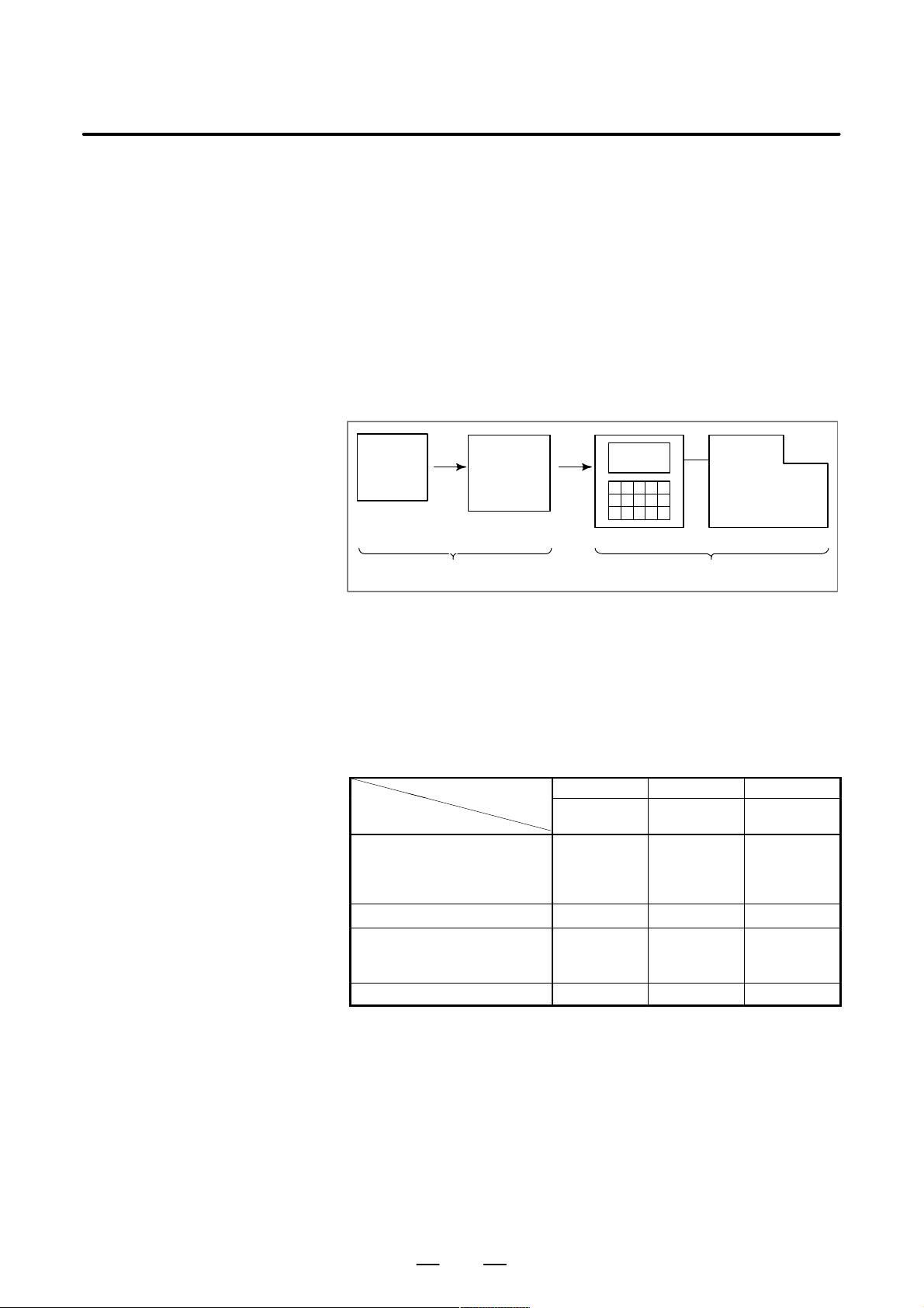
When machining the part using the CNC machine tool, first prepare the
program, then operate the CNC machine by using the program.
1) First, prepare the program from a part drawing to operate the CNC
machine tool.
How to prepare the program is described in the Chapter II.
PROGRAMMING.
2) The program is to be read into the CNC system. Then, mount the
workpieces and tools on the machine, and operate the tools according
to the programming. Finally, execute the machining actually.
How to operate the CNC system is described in the Chapter III.
OPERATION.
Part
drawing
CHAPTER II PROGRAMMING CHAPTER III OPERATION
Part
programming
CNC
MACHINE TOOL
Before the actual programming, make the machining plan for how to
machine the part.
Machining plan
1. Determination of workpieces machining range
2. Method of mounting workpieces on the machine tool
3. Machining sequence in every machining process
4. Machining tools and machining
Decide the machining method in every machining process.
Machining process
Machining process
Machining procedure
1. Machining method
: Rough
Semi
Finish
2. Machining tools
3. Machining conditions
: Feedrate
Cutting depth
4. Tool path
1 2 3
Feed cutting Side cutting
Hole
machining
7
Page 30
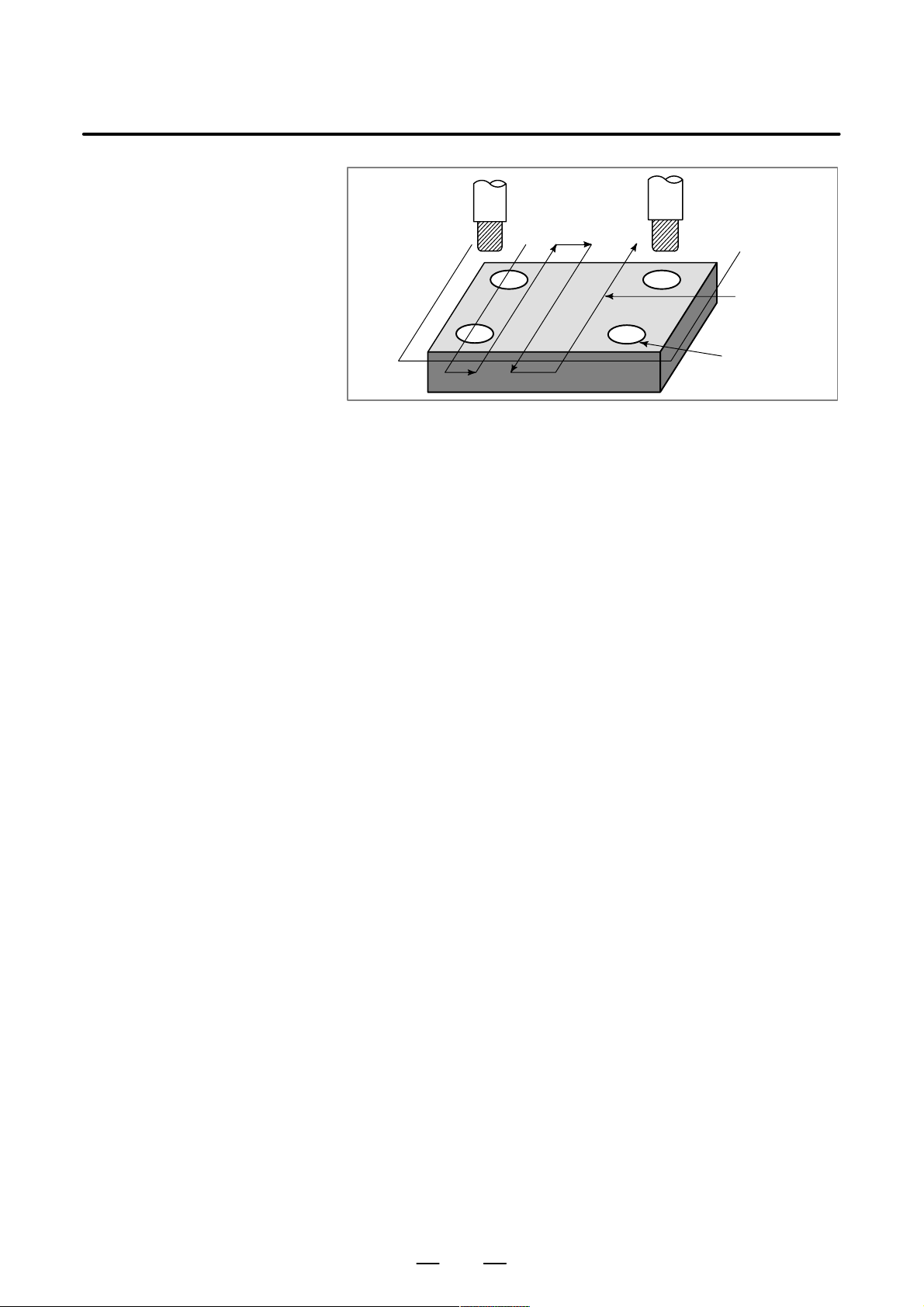
GENERAL1. GENERAL
Tool
Side cutting
B–63094EN/02
Face cutting
Hole machining
Prepare the program of the tool path and machining condition
according to the workpiece figure, for each machining.
8
Page 31

B–63094EN/02
1.2
NOTES ON
READING THIS
MANUAL
GENERAL
NOTE
1 The function of an CNC machine tool system depends not
only on the CNC, but on the combination of the machine
tool, its magnetic cabinet, the servo system, the CNC, the
operator’s panels, etc. It is too difficult to describe the
function, programming, and operation relating to all
combinations. This manual generally describes these from
the stand–point of the CNC. So, for details on a particular
CNC machine tool, refer to the manual issued by the
machine tool builder, which should take precedence over
this manual.
2 Headings are placed in the left margin so that the reader can
easily access necessary information. When locating the
necessary information, the reader can save time by
searching though these headings.
3 Machining programs, parameters, variables, etc. are stored
in the CNC unit internal non–volatile memory. In general,
these contents are not lost by the switching ON/OFF of the
power. However, it is possible that a state can occur where
precious data stored in the non–volatile memory has to be
deleted, because of deletions from a maloperation, or by a
failure restoration. In order to restore rapidly when this kind
of mishap occurs, it is recommended that you create a copy
of the various kinds of data beforehand.
4 This manual describes as many reasonable variations in
equipment usage as possible. It cannot address every
combination of features, options and commands that
should not be attempted.
If a particular combination of operations is not described, it
should not be attempted.
1. GENERAL
9
Page 32

II. PROGRAMMING
Page 33

B–63094EN/02
1
GENERAL
PROGRAMMING
1. GENERAL
13
Page 34

PROGRAMMING1. GENERAL
B–63094EN/02
1.1
TOOL MOVEMENT
ALONG WORKPIECE
P ARTS FIGURE–
INTERPOLATION
Explanations
D Tool movement along a
straight line
The tool moves along straight lines and arcs constituting the workpiece
parts figure (See II–4).
The function of moving the tool along straight lines and arcs is called the
interpolation.
Tool
Workpiece
Program
G01 X_ _ Y_ _ ;
X_ _ ;
D Tool movement along an
arc
Fig. 1.1 (a) T ool movement along a straight line
Program
G03X_ _Y_ _R_ _;
Tool
Workpiece
Fig. 1.1 (b) T ool movement along an arc
14
Page 35

B–63094EN/02
PROGRAMMING
1. GENERAL
Symbols of the programmed commands G01, G02, ... are called the
preparatory function and specify the type of interpolation conducted in
the control unit.
(a) Movement along straight line
G01 Y_ _;
X– –Y– – – –;
Control unit
Interpolation
a)Movement
along straight
line
b)Movement
along arc
Fig. 1.1 (c) Interpolation function
(b) Movement along arc
G03X––Y––R––;
X axis
Y axis
Tool
movement
NOTE
Some machines move tables instead of tools but this
manual assumes that tools are moved against workpieces.
15
Page 36

PROGRAMMING1. GENERAL
B–63094EN/02
1.2
FEED–FEED
FUNCTION
Movement of the tool at a specified speed for cutting a workpiece is called
the feed.
mm/min
F
Workpiece
Table
Fig. 1.2 Feed function
Tool
Feedrates can be specified by using actual numerics. For example, to feed
the tool at a rate of 150 mm/min, specify the following in the program:
F150.0
The function of deciding the feed rate is called the feed function (See
II–5).
16
Page 37

B–63094EN/02
1.3
PART DRAWING AND
TOOL MOVEMENT
PROGRAMMING
1. GENERAL
1.3.1
Reference Position
(Machine–Specific
Position)
Explanations
A CNC machine tool is provided with a fixed position. Normally, tool
change and programming of absolute zero point as described later are
performed at this position. This position is called the reference position.
Reference position
Tool
Workpiece
Table
Fig. 1.3.1 Reference position
The tool can be moved to the reference position in two ways:
(1)Manual reference position return (See III–3.1)
Reference position return is performed by manual button operation.
(2)Automatic reference position return (See II–6)
In general, manual reference position return is performed first after the
power is turned on. In order to move the tool to the reference position
for tool change thereafter, the function of automatic reference position
return is used.
17
Page 38

1.3.2
Coordinate System on
Part Drawing and
Coordinate System
Specified by CNC –
Coordinate System
PROGRAMMING1. GENERAL
Z
Y
Program
Z
B–63094EN/02
Y
Explanations
D Coordinate system
X
Part drawing
Fig. 1.3.2 (a)
X
Coordinate system
CNC
Command
Tool
Z
Y
Workpiece
X
Machine tool
Coordinate system
The following two coordinate systems are specified at different locations:
(See II–7)
(1)Coordinate system on part drawing
The coordinate system is written on the part drawing. As the program
data, the coordinate values on this coordinate system are used.
(2)Coordinate system specified by the CNC
The coordinate system is prepared on the actual machine tool table.
This can be achieved by programming the distance from the current
position of the tool to the zero point of the coordinate system to be set.
Y
230
300
Program
zero point
Fig. 1.3.2 (b) Coordinate system specified by the CNC
18
Present tool position
Distance to the zero point of a coordinate system to be set
X
Page 39

B–63094EN/02
PROGRAMMING
1. GENERAL
The positional relation between these two coordinate systems is
determined when a workpiece is set on the table.
Coordinate system on
part drawing established on the work-
Coordinate system specified by the CNC established on the table
Table
Fig. 1.3.2 (c) Coordinate system specified by CNC and coordinate
systemon part drawing
Y
Y
Workpiece
piece
X
X
D Methods of setting the
two coordinate systems
in the same position
The tool moves on the coordinate system specified by the CNC in
accordance with the command program generated with respect to the
coordinate system on the part drawing, and cuts a workpiece into a shape
on the drawing.
Therefore, in order to correctly cut the workpiece as specified on the
drawing, the two coordinate systems must be set at the same position.
To set the two coordinate systems at the same position, simple methods
shall be used according to workpiece shape, the number of machinings.
(1)Using a standard plane and point of the workpiece.
Y
Fixed distance
Program
zero point
Bring the tool center to the workpiece standard point.
And set the coordinate system specified by CNC at this position.
Workpiece’s
standard point
Fixed distance
X
19
Page 40

PROGRAMMING1. GENERAL
B–63094EN/02
(2)Mounting a workpiece directly against the jig
Program zero point
Jig
Meet the tool center to the reference position. And set the coordinate system
specified by CNC at this position. (Jig shall be mounted on the predetermined
point from the reference position.)
(3)Mounting a workpiece on a pallet, then mounting the workpiece and
pallet on the jig
Pallet
Jig
Workpiece
(Jig and coordinate system shall be specified by the same as (2)).
20
Page 41

B–63094EN/02
1.3.3
How to Indicate
Command Dimensions
for Moving the Tool –
Absolute, Incremental
Commands
PROGRAMMING
1. GENERAL
Explanations
D Absolute command
Command for moving the tool can be indicated by absolute command or
incremental command (See II–8.1).
The tool moves to a point at “the distance from zero point of the
coordinate system” that is to the position of the coordinate values.
Z
X
Command specifying movement from
point A to point B
Y
B(10.0,30.0,20.0)
G90 X10.0 Y30.0 Z20.0 ;
Coordinates of point B
Tool
A
D Incremental command
Specify the distance from the previous tool position to the next tool
position.
Z
Tool
A
X=40.0
Y
Z=–10.0
B
X
Command specifying movement from
point A to point B
21
Y=–30.0
G91 X40.0 Y–30.0 Z–10.0
Distance and direction for
movement along each axis
;
Page 42

PROGRAMMING1. GENERAL
B–63094EN/02
1.4
CUTTING SPEED –
SPINDLE SPEED
FUNCTION
Examples
The speed of the tool with respect to the workpiece when the workpiece
is cut is called the cutting speed.
As for the CNC, the cutting speed can be specified by the spindle speed
in rpm unit.
Tool
Spindle speed N
rpm
Workpiece
T ool diameter
f D mm
V: Cutting speed
m/min
<When a workpiece should be machined with a tool 100 mm in
diameter at a cutting speed of 80 m/min. >
The spindle speed is approximately 250 rpm, which is obtained from
N=1000v/πD. Hence the following command is required:
S250;
Commands related to the spindle speed are called the spindle speed
function ( See II–9) .
22
Page 43

B–63094EN/02
PROGRAMMING
1. GENERAL
1.5
SELECTION OF T OOL
USED FOR VARIOUS
MACHINING – TOOL
FUNCTION
Examples
When drilling, tapping, boring, milling or the like, is performed, it is
necessary to select a suitable tool. When a number is assigned to each tool
and the number is specified in the program, the corresponding tool is
selected.
Tool number
01
02
ATC magazine
<When No.01 is assigned to a drilling tool>
When the tool is stored at location 01 in the ATC magazine, the tool
can be selected by specifying T01. This is called the tool function (See
II–10).
23
Page 44

PROGRAMMING1. GENERAL
B–63094EN/02
1.6
COMMAND FOR
MACHINE
OPERATIONS –
MISCELLANEOUS
FUNCTION
When machining is actually started, it is necessary to rotate the spindle,
and feed coolant. For this purpose, on–off operations of spindle motor and
coolant valve should be controlled.
Tool
Coolant
Workpiece
The function of specifying the on–off operations of the components of the
machine is called the miscellaneous function. In general, the function is
specified by an M code (See II–11).
For example, when M03 is specified, the spindle is rotated clockwise at
the specified spindle speed.
24
Page 45

B–63094EN/02
PROGRAMMING
1. GENERAL
1.7
PROGRAM CONFIGURATION
A group of commands given to the CNC for operating the machine is
called the program. By specifying the commands, the tool is moved along
a straight line or an arc, or the spindle motor is turned on and off.
In the program, specify the commands in the sequence of actual tool
movements.
Block
Block
Tool movement sequence
Block
Program
Fig. 1.7 (a) Program configuration
Block
⋅
⋅
⋅
⋅
Block
A group of commands at each step of the sequence is called the block.
The program consists of a group of blocks for a series of machining. The
number for discriminating each block is called the sequence number, and
the number for discriminating each program is called the program
number (See II–12).
25
Page 46

PROGRAMMING1. GENERAL
B–63094EN/02
Explanations
D Block
D Program
The block and the program have the following configurations.
1 block
N ffff G ff Xff.f Yfff.f M ff S ff T ff ;
Sequence
number
Preparatory
function
Dimension word Miscel-
laneous
function
Fig. 1.7 (b) Block configuration
Spindle
function
Tool
function
End of
block
A block starts with a sequence number to identify the block and ends with
an end–of–block code.
This manual indicates the end–of–block code by ; (LF in the ISO code and
CR in the EIA code).
;
Offff;
⋅
⋅
⋅
M30 ;
Fig. 1.7 (c) Program configuration
Program number
Bloc
k
Bloc
k
⋅
Bloc
⋅
k
⋅
End of program
Normally, a program number is specified after the end–of–block (;) code
at the beginning of the program, and a program end code (M02 or M30)
is specified at the end of the program.
26
Page 47

B–63094EN/02
PROGRAMMING
1. GENERAL
D Main program and
subprogram
When machining of the same pattern appears at many portions of a
program, a program for the pattern is created. This is called the
subprogram. On the other hand, the original program is called the main
program. When a subprogram execution command appears during
execution of the main program, commands of the subprogram are
executed. When execution of the subprogram is finished, the sequence
returns to the main program.
Main program
⋅
⋅
M98P1001
⋅
⋅
⋅
M98P1002
⋅
⋅
⋅
M98P1001
⋅
⋅
Subprogram #1
O1001
M99
Subprogram #2
O1002
Program for
hole #1
Program for
hole #2
⋅
M99
Hole #1
Hole #1
Hole #2
Hole #2
27
Page 48

1.8
TOOL FIGURE AND TOOL MOTION BY PROGRAM
Explanations
PROGRAMMING1. GENERAL
B–63094EN/02
D Machining using the end
of cutter – Tool length
compensation function
(See II–14.1)
D Machining using the side
of cutter – Cutter
compensation function
(See II–14.4,14.5,14.6)
Usually, several tools are used for machining one workpiece. The tools
have different tool length. It is very troublesome to change the program
in accordance with the tools.
Therefore, the length of each tool used should be measured in advance.
By setting the difference between the length of the standard tool and the
length of each tool in the CNC (data display and setting : see III–11),
machining can be performed without altering the program even when the
tool is changed. This function is called tool length compensation.
Standard
tool
H1
H2
Workpiece
H3 H4
Because a cutter has a radius, the center of the cutter path goes around the
workpiece with the cutter radius deviated.
Cutter path using cutter
compensation
Machined part
figure
Workpiece
Cutter
If radius of cutters are stored in the CNC (Data Display and Setting : see
III–11), the tool can be moved by cutter radius apart from the machining
part figure. This function is called cutter compensation.
28
Page 49

B–63094EN/02
PROGRAMMING
1. GENERAL
1.9
TOOL MOVEMENT
RANGE – STROKE
Limit switches are installed at the ends of each axis on the machine to
prevent tools from moving beyond the ends. The range in which tools can
move is called the stroke.
Table
Motor
Limit switch
Machine zero point
Specify these distances.
Tools cannot enter this area. The area is specified by data in memory or
a program.
Besides strokes defined with limit switches, the operator can define an
area which the tool cannot enter using a program or data in memory . This
function is called stroke check (see III–6.3).
29
Page 50

2
PROGRAMMING2. CONTROLLED AXES
CONTROLLED AXES
B–63094EN/02
30
Page 51

B–63094EN/02
2.1
CONTROLLED AXES
PROGRAMMING 2. CONTROLLED AXES
2.2
AXIS NAME
Item
No. of basic controlled axes 3 axes
Controlled axes expansion (total) Max. 4 axes (included in Cs axis)
Basic simultaneously controlled axes 2 axes
Simultaneously controlled axes
expansion (total)
Max. 4 axes
21i–MA
210i–MA
NOTE
The number of simultaneously controllable axes for manual
operation jog feed, manual reference position return, or
manual rapid traverse) is 1 or 3 (1 when bit 0 (JAX) of
parameter 1002 is set to 0 and 3 when it is set to 1).
The names of three basic axes are always X, Y, and Z. The name of an
additional axis can be set to A, B, C, U, V , or W by using parameter 1020.
Parameter No. 1020 is used to determine the name of each axis.
When this parameter is set to 0 or a character other than the valid
characters is specified, an axis name from 1 to 4 is assigned by default.
Limitations
D Default axis name
D Duplicate axis names
When a default axis name (1 to 4) is used, operation in the MEM mode
and MDI mode is disabled.
If a duplicate axis name is specified in the parameter, operation is enabled
only for the axis specified first.
31
Page 52

PROGRAMMING2. CONTROLLED AXES
B–63094EN/02
2.3
INCREMENT SYSTEM
The increment system consists of the least input increment (for input) and
least command increment (for output). The least input increment is the
least increment for programming the travel distance. The least command
increment is the least increment for moving the tool on the machine. Both
increments are represented in mm, inches, or deg.
Name of increment system
IS–B
IS–C
Least input increment
0.001mm
0.0001inch
0.001deg
0.0001mm
0.00001inch
0.0001deg
Least command
increment
0.001mm
0.0001inch
0.001deg
0.0001mm
0.00001inch
0.0001deg
Maximum stroke
99999.999mm
9999.9999inch
99999.999deg
9999.9999mm
999.99999inch
9999.9999deg
The least command increment is either metric or inch depending on the
machine tool. Set metric or inch to the parameter INM (No.100#0).
For selection between metric and inch for the least input increment, G
code (G20 or G21) or a setting parameter selects it.
Combined use of the inch system and the metric system is not allowed.
There are functions that cannot be used between axes with different unit
systems (circular interpolation, cutter compensation, etc.). For the
increment system, see the machine tool builder’s manual.
2.4
MAXIMUM STROKE
Maximum stroke = Least command increment 99999999
See 2.3 Incremen System.
T able 2.4 Maximum strokes
Increment system Maximum stroke
Metric machine system "99999.999 mm
"99999.999 deg
IS–B
Inch machine system "9999.9999 inch
"99999.999 deg
Metric machine system "9999.9999 mm
"9999.9999 deg
IS–C
Inch machine system "999.99999 inch
"9999.9999 deg
NOTE
1 A command exceeding the maximum stroke cannot be
specified.
2 The actual stroke depends on the machine tool.
32
Page 53

B–63094EN/02
3
3. PREPARATORY FUNCTION
PROGRAMMING
PREPARATORY FUNCTION (G FUNCTION)
A number following address G determines the meaning of the command
for the concerned block.
G codes are divided into the following two types.
Type Meaning
One–shot G code The G code is effective only in the block in which it is
specified.
Modal G code The G code is effective until another G code of the
same group is specified.
(Example )
G01 and G00 are modal G codes in group 01.
(G FUNCTION)
G01X ;
Z;
X;
G00Z
G01 is effective in this range.
;
33
Page 54

3. PREPARATORY FUNCTION
(G FUNCTION)
PROGRAMMING
B–63094EN/02
Explanations
1. When the clear state (bit 6 (CLR) of parameter No. 3402) is set at
power–up or reset, the modal G codes are placed in the states
described below.
(1) The modal G codes are placed in the states marked with
as
indicated in Table 3.
(2) G20 and G21 remain unchanged when the clear state is set at
power–up or reset.
(3) Which status G22 or G23 at power on is set by parameter G23 (No.
3402#7). However, G22 and G23 remain unchanged when the
clear state is set at reset.
(4) The user can select G00 or G01 by setting bit 0 (G01) of parameter
No. 3402.
(5) The user can select G90 or G91 by setting bit 3 (G91) of parameter
No. 3402.
(6) The user can select G17, G18, or G19 by setting bit 1 (parameterG18)
and bit 2 (parameter G19) of parameter No. 3402.
2.G codes other than G10 and G11 are one–shot G codes.
3.When a G code not listed in the G code list is specified, or a G code
that has no corresponding option is specified, P/S alarm No. 010 is
output.
4.Multiple G codes can be specified in the same block if each G code
belongs to a different group. If multiple G codes that belong to the
same group are specified in the same block, only the last G code
specified is valid.
5.If a G code belonging to group 01 is specified in a canned cycle, the
canned cycle is cancelled. This means that the same state set by
specifying G80 is set. Note that the G codes in group 01 are not
affected by a G code specifying a canned cycle.
6.G codes are indicated by group.
7.The group of G60 is switched according to the setting of the MDL bit
(bit 0 of parameter 5431). (When the MDL bit is set to 0, the 00 group
is selected. When the MDL bit is set to 1, the 01 group is selected.)
34
Page 55

B–63094EN/02
3. PREPARATORY FUNCTION
PROGRAMMING
Table 3 G code list (1/3)
G code
G00
G01
G02
G03 Circular interpolation/Helical interpolation CCW
G04 Dwell, Exact stop
G05 High speed cycle machining
G07 Hypothetical axis interpolation
G07.1 (G107) Cylindrical interpolation
G08
G09 Exact stop
G10 Programmable data input
G11 Programmable data input mode cancel
G15
G16
G17
G18
G19
G20 Input in inch
G21
G22
G23
G25
G26
G27 Reference position return check
G28 Return to reference position
G29 00 Return from reference position
G30 2nd, 3rd and 4th reference position return
G31 Skip function
G33 01 Thread cutting
G37 Automatic tool length measurment
G39
G40
G41
G42 Cutter compensation right
G40.1 (G150)
G41.1 (G151) 19 Normal direction control left side on
G42.1 (G152) Normal direction control right side on
G43 Tool length compensation + direction
G44
Group Function
Positioning
01
00
17
02 ZpXp plane selection Yp: Y axis or its parallel axis
06
04
24
00
07
08
Linear interpolation
Circular interpolation/Helical interpolation CW
Look–ahead control
Polar coordinates command cancel
Polar coordinates command
XpY p plane selection Xp: X axis or its parallel axis
YpZp plane selection Zp: Z axis or its parallel axis
Input in mm
Stored stroke check function on
Stored stroke check function off
Spindle speed fluctuation detection off
Spindle speed fluctuation detection on
Corner offset circular interpolation
Cutter compensation cancel/Three dimensional compensation cancel
Cutter compensation left/Three dimensional compensation
Normal direction control cancel mode
Tool length compensation – direction
(G FUNCTION)
35
Page 56

3. PREPARATORY FUNCTION
(G FUNCTION)
G code
G45 Tool offset increase
G46 Tool offset decrease
G47
G48 Tool offset double decrease
G49
G50
G51
G50.1
G51.1
G52 Local coordinate system setting
G53
G54
G54.1 Additional workpiece coordinate system selection
G55
G56
G57 Workpiece coordinate system 4 selection
G58 Workpiece coordinate system 5 selection
G59 Workpiece coordinate system 6 selection
G60 00 Single direction positioning
G61 Exact stop mode
G62 Automatic corner override
G63
G64
G65 00 Macro call
G66 Macro modal call
G67
G68 Coordinate rotation/Three dimensional coordinate conversion
G69
G73 Peck drilling cycle
G74
G76
G80 Canned cycle cancel/external operation function cancel
G81
G82 Drilling cycle or counter boring cycle
G83 Peck drilling cycle
G84
G85 Boring cycle
G86 Boring cycle
G87 Back boring cycle
G88 Boring cycle
G89 Boring cycle
PROGRAMMING
Table 3 G code list (2/3)
Group Function
00
08 Tool length compensation cancel
11
22
00
14
15
12
16
09
09
09
Tool offset double increase
Scaling cancel
Scaling
Programmable mirror image cancel
Programmable mirror image
Machine coordinate system selection
Workpiece coordinate system 1 selection
Workpiece coordinate system 2 selection
Workpiece coordinate system 3 selection
Tapping mode
Cutting mode
Macro modal call cancel
Coordinate rotation cancel/Three dimensional coordinate conversion
cancel
Counter tapping cycle
Fine boring cycle
Drilling cycle, spot boring cycle or external operation function
Tapping cycle
B–63094EN/02
36
Page 57

B–63094EN/02
3. PREPARATORY FUNCTION
PROGRAMMING
Table 3 G code list (3/3)
G code
G90
G91
G92 Setting for work coordinate system or clamp at maximum spindle speed
G92.1
G94
G95
G96 Constant surface speed control
G97
G98
G99
Group Function
03
00
05
13
10
Absolute command
Increment command
Workpiece coordinate system preset
Feed per minute
Feed per rotation
Constant surface speed control cancel
Return to initial point in canned cycle
Return to R point in canned cycle
(G FUNCTION)
37
Page 58

4
PROGRAMMING4. INTERPOLATION FUNCTIONS
INTERPOLATION FUNCTIONS
B–63094EN/02
38
Page 59

B–63094EN/02
PROGRAMMING
4. INTERPOLATION FUNCTIONS
4.1
POSITIONING
(G00)
Format
Explanations
The G00 command moves a tool to the position in the workpiece system
specified with an absolute or an incremental command at a rapid traverse
rate.
In the absolute command, coordinate value of the end point is
programmed.
In the incremental command the distance the tool moves is programmed.
G00 _;IP
_: For an absolute command, the coordinates of an end
IP
position, and for an incremental commnad, the distance
the tool moves.
Either of the following tool paths can be selected according to bit 1 of
parameter LRP No. 1401.
D Nonlinear interpolation positioning
The tool is positioned with the rapid traverse rate for each axis
separately. The tool path is normally straight.
D Linear interpolation positioning
The tool path is the same as in linear interpolation (G01). The tool
is positioned within the shortest possible time at a speed that is not
more than the rapid traverse rate for each axis.
Start position
Linear interpolation positioning
End position
Non linear interpolation positioning
The rapid traverse rate in G00 command is set to the parameter No. 1420
for each axis independently by the machine tool builder. In the
posiitoning mode actuated by G00, the tool is accelerated to a
predetermined speed at the start of a block and is decelerated at the end
of a block. Execution proceeds to the next block after confirming the
in–position.
“In–position ” means that the feed motor is within the specified range.
This range is determined by the machine tool builder by setting to
parameter (No. 1826).
In–position check for each block can be disabled by setting bit 5 (NCI)
of parameter No.1601 accordingly.
39
Page 60

PROGRAMMING4. INTERPOLATION FUNCTIONS
B–63094EN/02
Limitations
The rapid traverse rate cannot be specified in the address F.
Even if linear interpolation positioning is specified, nonlinear
interpolation positioning is used in the following cases. Therefore, be
careful to ensure that the tool does not foul the workpiece.
D G28 specifying positioning between the reference and intermediate
positions.
D G53
40
Page 61

B–63094EN/02
PROGRAMMING
4. INTERPOLATION FUNCTIONS
4.2
SINGLE DIRECTION
POSITIONING (G60)
Format
For accurate positioning without play of the machine (backlash), final
positioning from one direction is available.
Overrun
Start position
Start position
End position
G60 _;
IP
_ : For an absolute command, the coordinates of an end
IP
position, and for an incremental commnad, the distance
the tool moves.
Temporary stop
Explanations
Examples
An overrun and a positioning direction are set by the parameter (No.
5440). Even when a commanded positioning direction coincides with
that set by the parameter, the tool stops once before the end point.
G60, which is an one–shot G–code, can be used as a modal G–code in
group 01 by setting 1 to the parameter (No. 5431 bit 0 MDL).
This setting can eliminate specifying a G60 command for every block.
Other specifications are the same as those for an one–shot G60 command.
When an one–shot G code is sepcified in the single direction positioning
mode, the one–shot G command is effective like G codes in group 01.
When one–shot
G60 commands are used.
G90;
G60 X0Y0;
G60 X100;
G60 Y100;
G04 X10;
G00 X0Y0;
Single direction
positioning
When modal
G60 command is used.
G90G60;
X0Y0;
X100;
Y100;
G04X10;
G00X0Y0;
Single direction
positioning mode start
Single direction
positioning
Dwell
Single direction
positioning
mode cancel
41
Page 62

PROGRAMMING4. INTERPOLATION FUNCTIONS
B–63094EN/02
Restrictions
D During canned cycle for drilling, no single direction positioning is
effected in Z axis.
D No single direction positioning is effected in an axis for which no
overrun has been set by the parameter.
D When the move distance 0 is commanded, the single direction
positioning is not performed.
D The direction set to the parameter is not effected by mirror image.
D The single direction positioning does not apply to the shift motion in
the canned cycles of G76 and G87.
42
Page 63

B–63094EN/02
PROGRAMMING
4. INTERPOLATION FUNCTIONS
4.3
LINEAR
INTERPOLATION
(G01)
Format
Explanations
Tools can move along a line
IP
G01 _F_;
_:For an absolute command, the coordinates of an end point ,
IP
and for an incremental commnad, the distance the tool moves.
F_:Speed of tool feed (Feedrate)
A tools move along a line to the specified position at the feedrate
specified in F.
The feedrate specified in F is effective until a new value is specified. It
need not be specified for each block.
The feedrate commanded by the F code is measured along the tool path.
If the F code is not commanded, the feedrate is regarded as zero.
The feedrate of each axis direction is as follows.
G01ααββγγζζ
Feed rate of α axis direction :
Feed rate of β axis direction :
Feed rate of γ axis direction :
Feed rate of ζ axis direction :
Ǹ
L + a2) b2) g2) z
Ff ;
a
Fa +
f
L
b
Fb+
f
L
g
Fg +
f
L
z
Fz+
f
L
2
The feed rate of the rotary axis is commanded in the unit of deg/min (the
unit is decimal point position).
When the straight line axis α(such as X, Y, or Z) and the rotating axisβ
(such as A, B, or C) are linearly interpolated, the feed rate is that in which
the tangential feed rate in the αandβ cartesian coordinate system is
commanded by F(mm/min).
β–axis feedrate is obtained ; at first, the time required for distribution is
calculated by using the above fromula, then the β –axis feedrate unit is
changed to deg 1min.
43
Page 64

PROGRAMMING4. INTERPOLATION FUNCTIONS
B–63094EN/02
A calcula;tion example is as follows.
G91 G01 X20.0B40.0 F300.0 ;
This changes the unit of the C axis from 40.0 deg to 40mm with metric
input. The time required for distribution is calculated as follows:
Examples
D Linear interpolation
Ǹ
202) 40
The feed rate for the C axis is
300
40
0.14907
2
0.14907 (min)8
8
268.3 degńmin
In simultaneous 3 axes control, the feed rate is calculated the same way
as in 2 axes control.
(G91) G01X200.0Y100.0F200.0 ;
Y axis
100.0
(End position)
D Feedrate for the
rotation axis
(Start position)
G91G01C–90.0 G300.0 ;Feed rate of 300deg/min
(End point)
200.00
(Start point)
90°
Feedrate is 300 deg/min
X axis
44
Page 65

B–63094EN/02
PROGRAMMING
4. INTERPOLATION FUNCTIONS
4.4
CIRCULAR
INTERPOLATION
(G02,G03)
Format
The command below will move a tool along a circular arc.
Arc in the XpYp plane
G17
Arc in the ZpXp plane
G18
Arc in the YpZpplane
G19
G02
G03
G02
G03
G02
G03
Xp_Yp_
Xp_ p_
Yp_ Zp_
I_ J_
R_
I_ K_
R_
J_ K_
R_
F_ ;
F_
F_
T able 4.4 Description of the command format
Command Description
G17 Specification of arc on XpY p plane
G18 Specification of arc on ZpXp plane
G19 Specification of arc on Y pZp plane
G02 Circular Interpolation Clockwise direction (CW)
G03 Circular Interpolation Counterclockwise direction (CCW)
X
p_
Y
p_
Z
p_
I_ Xp axis distance from the start point to the center of an arc
J_ Yp axis distance from the start point to the center of an arc
Command values of X axis or its parallel axis
(set by parameter No. 1022)
Command values of Y axis or its parallel axis
(set by parameter No. 1022)
Command values of Z axis or its parallel axis
(set by parameter No. 1022)
with sign
with sign
k_ Zp axis distance from the start point to the center of an arc
with sign
R_ Arc radius (with sign)
F_ Feedrate along the arc
45
Page 66

Explanations
PROGRAMMING4. INTERPOLATION FUNCTIONS
B–63094EN/02
D Direction of the circular
interpolation
D Distance moved on an
arc
D Distance from the start
point to the center of arc
“Clockwise”(G02) and “counterclockwise”(G03) on the XpYp plane
plane or YpZp plane) are defined when the XpYp plane is viewed
(Z
pXp
in the positive–to–negative direction of the Z
axis (Yp axis or Xp axis,
p
respectively) in the Cartesian coordinate system. See the figure below.
Yp Xp Zp
G18
G03
Zp
G03
G02
Yp
G19
G02
G17
G03
G02
Xp
The end point of an arc is specified by address Xp, Yp or Zp, and is
expressed as an absolute or incremental value according to G90 or G91.
For the incremental value, the distance of the end point which is viewed
from the start point of the arc is specified.
The arc center is specified by addresses I, J, and K for the Xp, Y p, and Zp
axes, respectively . The numerical value following I, J, or K, however, is
a vector component in which the arc center is seen from the start point,
and is always specified as an incremental value irrespective of G90 and
G91, as shown below.
I, J, and K must be signed according to the direction.
End point (x,y)
yx
x
Center
i
Start
point
j
End point (z,x)
z
Center
k
Start
point
i
I0,J0, and K0 can be omitted. When Xp, Yp , and Z
End point (y ,z)
z
y
j
Center
are omitted (the end
p
Start
point
k
point is the same as the start point) and the center is specified with I, J,
and K, a 360° arc (circle) is specified.
G021; Command for a circle
If the difference between the radius at the start point and that at the
end point exceeds the permitted value in a parameter (No.3410), an P/S
alarm (No.020) occurs.
46
Page 67

B–63094EN/02
PROGRAMMING
4. INTERPOLATION FUNCTIONS
D Arc radius
The distance between an arc and the center of a circle that contains the arc
can be specified using the radius, R, of the circle instead of I, J, and K.
In this case, one arc is less than 180°, and the other is more than 180° are
considered. When an arc exceeding 180° is commanded, the radius must
be specified with a negative value. If Xp, Yp, and Zp are all omitted, if
the end point is located at the same position as the start point and when
R is used, an arc of 0° is programmed
G02R ; (The cutter does not move.)
For arc (1)(less than 180°)
G91 G02 XP60.0 YP20.0 R50.0 F300.0 ;
For arc (2)(greater than 180°)
G91 G02 X
60.0 YP20.0 R–50.0 F300.0 ;
P
2
r=50mm
Start point
Y
End point
1
r=50mm
D Feedrate
Restrictions
X
The feedrate in circular interpolation is equal to the feed rate specified by
the F code, and the feedrate along the arc (the tangential feedrate of the
arc) is controlled to be the specified feedrate.
The error between the specified feedrate and the actual tool feedrate is
±2% or less. However, this feed rate is measured along the arc after the
cutter compensation is applied
If I, J, K, and R addresses are specified simultaneously, the arc specified
by address R takes precedence and the other are ignored.
If an axis not comprising the specified plane is commanded, an alarm is
displayed.
For example, if axis U is specified as a parallel axis to X axis when plane
XY is specified, an P/S alarm (No.028)is displayed.
When an arc having a center angle approaching 180° is specified, the
calculated center coordinates may contain an error . In such a case, specify
the center of the arc with I, J, and K.
47
Page 68

Examples
PROGRAMMING4. INTERPOLATION FUNCTIONS
B–63094EN/02
Y axis
100
50R
60
40
0
90 120
60R
140
The above tool path can be programmed as follows ;
(1) In absolute programming
G92X200.0 Y40.0 Z0 ;
G90 G03 X140.0 Y100.0R60.0 F300.;
G02 X120.0 Y60.0R50.0 ;
or
G92X200.0 Y40.0Z0 ;
G90 G03 X140.0 Y100.0I-60.0 F300.;
G02 X120.0 Y60.0I-50.0 ;
(2) In incremental programming
G91 G03 X-60.0 Y60.0 R60.0 F300.;
G02 X-20.0 Y-40.0 R50.0 ;
or
G91 G03 X-60.0 Y60.0 I-60.0 F300. ;
G02 X-20.0 Y-40.0 I-50.0 ;
200
X axis
48
Page 69

B–63094EN/02
4.5
HELICAL
INTERPOLATION
(G02,G03)
Format
PROGRAMMING
4. INTERPOLATION FUNCTIONS
Helical interpolation which moved helically is enabled by specifying up
to two other axes which move synchronously with the circular
interpolation by circular commands.
Synchronously with arc of XpY p plane
Explanations
G17
Synchronously with arc of ZpXp plane
G18
Synchronously with arc of Y pZp plane
G19
α,β:Any one axis where circular interpolation is not applied
G02
G03
G02
G03
G02
G03
Up to two other axes can be specified.
Xp_Yp_
Xp_Zp_
Yp_Zp_
I_J_
R_
I_K_
R_
J_K_
R_
α_(β_)F_;
α_(β_)F_;
α_(β_)F_;
.
The command method is to simply or secondary add a move command
axis which is not circular interpolation axes. An F command specifies a
feed rate along a circular arc. Therefore, the feed rate of the linear axis
is as follows:
Length of linear axis
F×
Length of circular arc
Determine the feed rate so the linear axis feed rate does not exceed any
of the various limit values.Bit 0 (HFC) of parameter No. 1404 can be used
to prevent the linear axis feedrate from exceeding various limit values.
Restrictions
Z
Tool path
YX
The feedrate along the circumference of two circular interpolated axes is the specified feedrate.
Cutter compensation is applied only for a circular arc.
Tool offset and tool length compensation cannot be used in a block in
which a helical interpolation is commanded.
49
Page 70

PROGRAMMING4. INTERPOLATION FUNCTIONS
B–63094EN/02
4.6
CYLINDRICAL
INTERPOLATION
(G07.1)
Format
The amount of travel of a rotary axis specified by an angle is once
internally converted to a distance of a linear axis along the outer surface
so that linear interpolation or circular interpolation can be performed with
another axis. After interpolation, such a distance is converted back to the
amount of travel of the rotary axis.
The cylindrical interpolation function allows the side of a cylinder to be
developed for programming. So programs such as a program for
cylindrical cam grooving can be created very easily.
G07.1 r ; Starts the cylindrical interpolation mode
IP
(enables cylindrical interpolation).
:
:
:
G07.1 0 ; The cylindrical interpolation mode is cancelled.
IP
: An address for the rotation axis
IP
r : The radius of the cylinder
Specify G07.1 r ; and G07.1 0; in separate blocks.
G107 can be used instead of G07.1.
IP IP
Explanations
D Plane selection
(G17, G18, G19)
D Feedrate
D Circular interpolation
(G02,G03)
Use parameter (No. 1022) to specify whether the rotation axis is the X–,
Y–, or Z–axis, or an axis parallel to one of these axes. Specify the G code
to select a plane for which the rotation axis is the specified linear axis.
For example, when the rotation axis is an axis parallel to the X–axis, G17
must specify an Xp–Y p plane, which is a plane defined by the rotation axis
and the Y–axis or an axis parallel to the Y–axis.
Only one rotation axis can be set for cylindrical interpolation.
A feedrate specified in the cylindrical interpolation mode is a speed on the
developed cylindrical surface.
In the cylindrical interpolation mode, circular interpolation is possible
with the rotation axis and another linear axis. Radius R is used in
commands in the same way as described in II–4.4.
The unit for a radius is not degrees but millimeters (for metric input) or
inches (for inch input).
< Example Circular interpolation between the Z axis and C axis >
For the C axis of parameter (No.1022), 5 (axis parallel with the X axis)
is to be set. In this case, the command for circular interpolation is
G18 Z__C__;
G02 (G03) Z__C__R__;
For the C axis of parameter (No.1022), 6 (axis parallel with the Y axis)
may be specified instead. In this case, however, the command for
circular interpolation is
G19 C__Z__;
G02 (G03) Z__C__R__;
50
Page 71

B–63094EN/02
PROGRAMMING
4. INTERPOLATION FUNCTIONS
D Tool offset
D Cylindrical interpolation
accuracy
To perform tool offset in the cylindrical interpolation mode, cancel any
ongoing cutter compensation mode before entering the cylindrical
interpolation mode. Then, start and terminate tool offset within the
cylindrical interpolation mode.
In the cylindrical interpolation mode, the amount of travel of a rotary axis
specified by an angle is once internally converted to a distance of a linear
axis on the outer surface so that linear interpolation or circular
interpolation can be performed with another axis. After interpolation,
such a distance is converted back to an angle. For this conversion, the
amount of travel is rounded to a least input increment.
So when the radius of a cylinder is small, the actual amount of travel can
differ from a specified amount of travel. Note, however , that such an error
is not accumulative.
If manual operation is performed in the cylindrical interpolation mode
with manual absolute on, an error can occur for the reason described
above.
The actual amount
of travel
MOTION REV
R
MOTION REV
=
2×2πR
The amount of travel per rotation of the rotation axis (Set-
:
ting value of parameter No. 1260)
:
Workpiece radius
Specified value
2×2πR
MOTION REV
Limitations
D Arc radius specification
in the cylindrical
interpolation mode
D Circular interpolation
and cutter compensation
D Positioning
D Coordinate system
setting
D Cylindrical interpolation
mode setting
:Rounded to the least input increment
In the cylindrical interpolation mode, an arc radius cannot be specified
with word address I, J, or K.
If the cylindrical interpolation mode is started when cutter compensation
is already applied, circular interpolation is not correctly performed in the
cylindrical interpolation mode.
In the cylindrical interpolation mode, positioning operations (including
those that produce rapid traverse cycles such as G28, G53, G73, G74,
G76, G80 through G89) cannot be specified. Before positioning can be
specified, the cylindrical interpolation mode must be cancelled.
Cylindrical interpolation (G07.1) cannot be performed in the positioning
mode (G00).
In the cylindrical interpolation mode, a workpiece coordinate system
(G92, G54 through G59) or local coordinate system (G52) cannot be
specified.
In the cylindrical interpolation mode, the cylindrical interpolation mode
cannot be reset. The cylindrical interpolation mode must be cancelled
before the cylindrical interpolation mode can be reset.
D Tool offset
D Index table indexing
function
A tool offset must be specified before the cylindrical interpolation mode
is set. No offset can be changed in the cylindrical interpolation mode.
Cylindrical interpolation cannot be specified when the index table index
function is being used.
51
Page 72

Examples
PROGRAMMING4. INTERPOLATION FUNCTIONS
B–63094EN/02
Example of a Cylindrical Interpolation Program
O0001 (CYLINDRICAL INTERPOLATION );
N01 G00 G90 Z100.0 C0 ;
N02 G01 G91 G18 Z0 C0 ;
N03 G07.1 C57299 ;
N04 G90 G01 G42 Z120.0 D01 F250 ;
N05 C30.0 ;
N06 G02 Z90.0 C60.0 R30.0 ;
N07 G01 Z70.0 ;
N08 G03 Z60.0 C70.0 R10.0 ;
N09 G01 C150.0 ;
N10 G03 Z70.0 C190.0 R75.0 ;
N11 G01 Z110.0 C230.0 ;
N12 G02 Z120.0 C270.0 R75.0 ;
N13 G01 C360.0 ;
N14 G40 Z100.0 ;
N15 G07.1 C0 ;
N16 M30 ;
C
RZ
mm
120
110
90
70
60
Z
N05
0
N06
N07
N08 N09 N10
30 60 70
150
N11
N12
230190
270
N13
360
deg
C
52
Page 73

B–63094EN/02
PROGRAMMING
4. INTERPOLATION FUNCTIONS
4.7
THREAD CUTTING (G33)
Format
Explanations
Straight threads with a constant lead can be cut. The position coder
mounted on the spindle reads the spindle speed in real–time. The read
spindle speed is converted to the feedrate per minute to feed the tool.
I
P
G33 _ F_ ;
F : Long axis direction lead
Z
Workpiece
X
In general, thread cutting is repeated along the same tool path in rough
cutting through finish cutting for a screw. Since thread cutting starts when
the position coder mounted on the spindle outputs a 1–turn signal,
threading is started at a fixed point and the tool path on the workpiece is
unchanged for repeated thread cutting. Note that the spindle speed must
remain constant from rough cutting through finish cutting. If not,
incorrect thread lead will occur.
In general, the lag of the servo system, etc. will produce somewhat
incorrect leads at the starting and ending points of a thread cut. To
compensate for this, a thread cutting length somewhat longer than
required should be specified.
Table 4.7 lists the ranges for specifying the thread lead.
T able. 4.7 Ranges of lead sizes that can be specified
mm input
Inch input
Least command
increment
0.001 mm F1 to F50000 (0.01 to 500.00mm)
0.0001 mm F1 to F50000 (0.01 to 500.00mm)
0.0001 inch F1 to F99999
0.00001 inch F1 to F99999
Command value range of the lead
(0.0001 to 9.9999inch)
(0.0001 to 9.9999inch)
53
Page 74

PROGRAMMING4. INTERPOLATION FUNCTIONS
NOTE
1 The spindle speed is limited as follows :
B–63094EN/02
1 x spindle speed x
Maximum feedrate
Thread lead
Spindle speed : rpm
Thread lead : mm or inch
Maximum feedrate : mm/min or inch/min ; maximum command–specified feedrate for
feed–per–minute mode or maximum feedrate that is determined based on mechanical
restrictions including those related to motors, whichever is smaller
2 Cutting feedrate override is not applied to the converted feedrate in all machining process from
rough cutting to finish cutting. The feedrate is fixed at 100%
3 The converted feedrate is limited by the upper feedrate specified.
4 Feed hold is disabled during threading. Pressing the feed hold key during thread cutting causes
the machine to stop at the end point of the next block after threading (that is, after the G33 mode
is terminated)
Examples
Thread cutting at a pitch of 1.5mm
G33 Z10. F1.5;
54
Page 75

B–63094EN/02
PROGRAMMING
4. INTERPOLATION FUNCTIONS
4.8
SKIP
FUNCTION(G31)
Format
Explanations
Linear interpolation can be commanded by specifying axial move
following the G31 command, like G01. If an external skip signal is input
during the execution of this command, execution of the command is
interrupted and the next block is executed.
The skip function is used when the end of machining is not programmed
but specified with a signal from the machine, for example, in grinding. It
is used also for measuring the dimensions of a workpiece.
G31 _ ;
IP
G31: One–shot G code (If is effective only in the block in which it
is specified)
The coordinate values when the skip signal is turned on can be used in a
custom macro because they are stored in the custom macro system
variable #5061 to #5064, as follows:
#5061 X axis coordinate value
#5062 Y axis coordinate value
#5063 Z axis coordinate value
#5064 4th axis coordinate value
WARNING
Disable feedrate override, dry run, and automatic
acceleration/deceleration (however, these become
available by setting the parameter SKF No.6200#7 to 1.)
when the feedrate per minute is specified, allowing for an
error in the position of the tool when a skip signal is input.
These functions are enabled when the feedrate per rotation
is specified.
NOTE
If G31 command is issued while cutter compensation C is
applied, an P/S alarm of No.035 is displayed. Cancel the
cutter compensation with the G40 command before the G31
command is specified.
55
Page 76

Examples
D The next block to G31 is
an incremental
command
PROGRAMMING4. INTERPOLATION FUNCTIONS
G31 G91X100.0 F100;
Y50.0;
B–63094EN/02
D The next block to G31 is
an absolute command
for 1 axis
Skip signal is input here
Y
X
Fig. 4.8 (a) The next block is an incremental command
G31 G90X200.00 F100;
Y100.0;
Skip signal is input here
100.0
50.0
Actual motion
Motion without skip signal
Y100.0
X200.0
D The next block to G31 is
an absolute command
for 2 axes
Actual motion
Motion without skip signal
Fig. 4.8 (b) The next block is an absolute command for 1 axis
G31 G90X200.0 F100;
X300.0 Y100.0;
Y
Skip signal is input here
100
100 200 300
Fig. 4.8 (c) The next block is an absolute command for 2 axes
(300,100)
Actual motion
Motion without skip signal
X
56
Page 77

B–63094EN/02
PROGRAMMING
4. INTERPOLATION FUNCTIONS
4.9
HIGH SPEED SKIP
SIGNAL (G31)
Format
The skip function operates based on a high–speed skip signal (connected
directly to the NC; not via the PMC) instead of an ordinary skip signal.
In this case, up to eight signals can be input.
Delay and error of skip signal input is 0 – 2 msec at the NC side (not
considering those at the PMC side).
This high–speed skip signal input function keeps this value to 0.1 msec
or less, thus allowing high precision measurement.
For details, refer to the appropriate manual supplied from the machine
tool builder.
G31 IP_ ;
IP
G31: One–shot G code (If is effective only in the block in which it is
specified)
57
Page 78

5
FEED FUNCTIONS
PROGRAMMING5. FEED FUNCTIONS
B–63094EN/02
58
Page 79

B–63094EN/02
PROGRAMMING
5. FEED FUNCTIONS
5.1
GENERAL
D Feed functions
D Override
D Automatic acceleration/
deceleration
The feed functions control the feedrate of the tool. The following two feed
functions are available:
1. Rapid traverse
When the positioning command (G00) is specified, the tool moves at
a rapid traverse feedrate set in the CNC (parameter No. 1420).
2. Cutting feed
The tool moves at a programmed cutting feedrate.
Override can be applied to a rapid traverse rate or cutting feedrate using
the switch on the machine operator’s panel.
T o prevent a mechanical shock, acceleration/deceleration is automatically
applied when the tool starts and ends its movement (Fig. 5.1 (a)).
Rapid traverse rate
F
: Rapid traverse
F
R
R
rate
: Acceleration/
T
R
deceleration time
constant for rapid traverse rate
0
T
R
Feed rate
C
0
T
C
Fig. 5.1 (a) Automatic acceleration/deceleration (example)
T
R
F
: Feedrate
CF
: Acceleration/
T
C
T
C
Time
deceleration time
constant for a cutting feedrate
Time
59
Page 80

PROGRAMMING5. FEED FUNCTIONS
B–63094EN/02
D Tool path in a cutting
feed
If the direction of movement changes between specified blocks during
cutting feed, a rounded–corner path may result (Fig. 5.1 (b)).
Y
Programmed path
Actual tool path
0
Fig. 5.1 (b) Example of tool path between two blocks
X
In circular interpolation, a radial error occurs (Fig. 5.1(c)).
Y
0
Fig. 5.1 (c) Example of radial error in circular interpolation
∆r:Error
Programmed path
Actual tool path
r
X
The rounded–corner path shown in Fig. 5.1(b) and the error shown in Fig.
5.1(c) depend on the feedrate. So, the feedrate needs to be controlled for
the tool to move as programmed.
60
Page 81

B–63094EN/02
5.2
RAPID TRAVERSE
Format
PROGRAMMING
IP
G00 IP_ ;
G00 : G code (group 01) for positioning (rapid traverse)
IP_ ; Dimension word for the end point
IP
5. FEED FUNCTIONS
Explanations
The positioning command (G00) positions the tool by rapid traverse. In
rapid traverse, the next block is executed after the specified feedrate
becomes 0 and the servo motor reaches a certain range set by the machine
tool builder (in–position check).
A rapid traverse rate is set for each axis by parameter No. 1420, so no rapid
traverse feedrate need be programmed.
The following overrides can be applied to a rapid traverse rate with the
switch on the machine operator’s panel:F0, 25, 50, 100%
F0: Allows a fixed feedrate to be set for each axis by parameter No. 1421.
For detailed information, refer to the appropriate manual of the machine
tool builder.
61
Page 82

PROGRAMMING5. FEED FUNCTIONS
B–63094EN/02
5.3
CUTTING FEED
Format
Feedrate of linear interpolation (G01), circular interpolation (G02, G03),
etc. are commanded with numbers after the F code.
In cutting feed, the next block is executed so that the feedrate change from
the previous block is minimized.
Four modes of specification are available:
1. Feed per minute (G94)
After F, specify the amount of feed of the tool per minute.
2. Feed per revolution (G95)
After F, specify the amount of feed of the tool per spindle revolution.
3. F1–digit feed
Specify a desired one–digit number after F. Then, the feedrate set with
the CNC for that number is set.
Feed per minute
G94 ; G code (group 05) for feed per minute
F_ ; Feedrate command (mm/min or inch/min)
Feed per revolution
G95 ; G code (group 05) for feed per revolution
F_ ; Feedrate command (mm/rev or inch/rev)
F1–digit feed
FN ;
N : Number from 1 to 9
Explanations
D Tangential speed
constant control
Cutting feed is controlled so that the tangential feedrate is always set at
a specified feedrate.
YY
End point
F
Start
point
X
Linear interpolation
Fig. 5.3 (a) Tangential feedrate (F)
Starting
point
F
Center End point
X
Circular interpolation
62
Page 83

B–63094EN/02
PROGRAMMING
5. FEED FUNCTIONS
D Feed per minute (G94)
After specifying G94 (in the feed per minute mode), the amount of feed
of the tool per minute is to be directly specified by setting a number after
F . G94 is a modal code. Once a G94 is specified, it is valid until G95 (feed
per revolution) is specified. At power–on, the feed per minute mode is
set.
An override from 0% to 254% (in 1% steps) can be applied to feed per
minute with the switch on the machine operator’s panel. For detailed
information, see the appropriate manual of the machine tool builder.
Feed amount per minute
(mm/min or inch/min)
Tool
Workpiece
Table
Fig. 5.3 (b) Feed per minute
WARNING
No override can be used for some commands such as for
threading.
D Feed per revolution
(G95)
After specifying G95 (in the feed per revolution mode), the amount of
feed of the tool per spindle revolution is to be directly specified by setting
a number after F . G95 is a modal code. Once a G95 is specified, it is valid
until G94 (feed per minute) is specified.
An override from 0% to 254% (in 1% steps) can be applied to feed per
revolution with the switch on the machine operator’s panel. For detailed
information, see the appropriate manual of the machine tool builder.
F
Feed amount per spindle revolution
(mm/rev or inch/rev)
Fig. 5.3 (c) Feed per revolution
CAUTION
When the speed of the spindle is low, feedrate fluctuation
may occur. The slower the spindle rotates, the more
frequently feedrate fluctuation occurs.
63
Page 84

PROGRAMMING5. FEED FUNCTIONS
B–63094EN/02
D One–digit F code feed
D Cutting feedrate clamp
When a one–digit number from 1 to 9 is specified after F, the feedrate
set for that number in a parameter (Nos. 1451 to 1459) is used. When
F0 is specified, the rapid traverse rate is applied.
The feedrate corresponding to the number currently selected can be
increased or decreased by turning on the switch for changing F1–digit
feedrate on the machine operator’s panel, then by rotating the manual
pulse generator .
The increment/decrement, ∆F, in feedrate per scale of the manual pulse
generator is as follows:
Fmax
∆
F +
100X
Fmax : feedrate upper limit for F1–F4 set by parameter (No.1460), or
feedrate upper limit for F5–F9 set by parameter (No.1461)
X :any value of 1–127 set by parameter (No.1450)
The feedrate set or altered is kept even while the power is off. The current
feed rate is displayed on the CRT screen.
A common upper limit can be set on the cutting feedrate along each axis
with parameter No. 1422. If an actual cutting feedrate (with an override
applied) exceeds a specified upper limit, it is clamped to the upper limit.
Parameter No. 1430 can be used to specify the maximum cutting feedrate
for each axis only for linear interpolation and circular interpolation.
When the cutting feedrate along an axis exceeds the maximum feedrate
for the axis as a result of interpolation, the cutting feedrate is clamped to
the maximum feedrate.
Reference
NOTE
An upper limit is set in mm/min or inch/min. CNC calculation
may involve a feedrate error of ±2% with respect to a
specified value. However, this is not true for
acceleration/deceleration. To be more specific, this error is
calculated with respect to a measurement on the time the
tool takes to move 500 mm or more during the steady state:
See Appendix C for range of feedrate command value.
64
Page 85

B–63094EN/02
PROGRAMMING
5. FEED FUNCTIONS
5.4
Cutting feedrate can be controlled, as indicated in Table 5.4.
CUTTING FEEDRATE CONTROL
T able 5.4 Cutting Feedrate Control
Function name G code Validity of G code Description
Exact stop G09
Exact stop mode G61
Cutting mode G64
Tapping mode G63
Auto–
matic
Automatic override for
inner corners
G62
This function is valid for specified
blocks only.
Once specified, this function is
valid until G62, G63, or G64 is
specified.
Once specified, this function is
valid until G61, G62, or G63 is
specified.
Once specified, this function is
valid until G61, G62, or G64 is
specified.
Once specified, this function is
valid until G61, G63, or G64 is
specified.
The tool is decelerated at the end point
of a block, then an in–position check is
made. Then the next block is executed.
The tool is decelerated at the end point
of a block, then an in–position check is
made. Then the next block is executed.
The tool is not decelerated at the end
point of a block, but the next block is
executed.
The tool is not decelerated at the end
point of a block, but the next block is
executed.
When G63 is specified, feedrate override
and feed hold are invalid.
When the tool moves along an inner
corner during cutter compensation, override is applied to the cutting feedrate to
suppress the amount of cutting per unit
of time so that a good surface finish can
be produced.
Internal circular cutting
feedrate change
This function is valid in the cutter
_
compensation mode, regardless of
the G code.
The internal circular cutting feedrate is
changed.
NOTE
1 The purpose of in–position check is to check that the servo
motor has reached within a specified range (specified with
a parameter by the machine tool builder).
In–position check is not performed when bit 5 (NCI) of
parameter No. 1601 is set to 1.
2 Inner corner angle θ: 2°
< θ x α x 178°
(α is a set value)
Workpiece
θ
Tool
65
Page 86

Format
PROGRAMMING5. FEED FUNCTIONS
B–63094EN/02
5.4.1
Exact Stop (G09, G61)
Cutting Mode (G64)
Tapping Mode (G63)
Explanations
Exact stop G09 IP_ ;
Exact stop mode G61 ;
Cutting mode G64 ;
Tapping mode G63 ;
Automatic corner override G62 ;
IP
The inter–block paths followed by the tool in the exact stop mode, cutting
mode, and tapping mode are different (Fig. 5.4.1).
Y
(2)
(1)
0
Position check
Tool path in the exact stop mode
Tool path in the cutting mode or
tapping mode
X
Fig. 5.4.1 Example of tool paths from block (1) to block (2)
CAUTION
The cutting mode (G64 mode) is set at power–on or system
clear.
66
Page 87

B–63094EN/02
PROGRAMMING
5. FEED FUNCTIONS
5.4.2
Automatic Corner Override
When cutter compensation is performed, the movement of the tool is
automatically decelerated at an inner corner and internal circular area.
This reduces the load on the cutter and produces a smoothly machined
surface.
5.4.2.1
Automatic Override for
Inner Corners (G62)
Explanations
D Override condition
1. Straight line–straight line 2. Straight line–arc
When G62 is specified, and the tool path with cutter compensation
applied forms an inner corner, the feedrate is automatically overridden
at both ends of the corner.
There are four types of inner corners (Fig. 5.4.2.1 (a)).
xθxθpx178, in Fig. 5.4.2.1 (a)
2,
θp is a value set with parameter No. 1711. When θ is approximately
equal to
θp, the inner corner is determined with an error of 0.001,or
less.
:Tool
:Programmed path
:Cutter center path
θ
3. Arc–straight line 4. Arc–arc
θ
Fig. 5.4.2.1 (a) Inner corner
θ
θ
67
Page 88

PROGRAMMING5. FEED FUNCTIONS
B–63094EN/02
Override range
When a corner is determined to be an inner corner, the feedrate is
overridden before and after the inner corner. The distances Ls and Le,
where the feedrate is overridden, are distances from points on the cutter
center path to the corner (Fig. 5.4.2.1 (b), Fig. 5.4.2.1 (c), Fig. 5.4.2.1 (d)).
Ls and Le are set with parameter Nos. 1713 and 1714.
Programmed path
Le
a
Cutter center path
The feedrate is overridden from point a to point b.
FIg. 5.4.2.1 (b) Override Range (Straight Line to Straight Line)
Ls
b
When a programmed path consists of two arcs, the feedrate is overridden
if the start and end points are in the same quadrant or in adjacent quadrants
(Fig. 5.4.2.1 (c)).
Le
Ls
a
Cutter center path
The feedrate is overridden from point a to b.
Fig. 5.4.2.1 (c) Override Range (Arc to Arc)
Programmed path
b
68
Page 89

B–63094EN/02
PROGRAMMING
5. FEED FUNCTIONS
Regarding program (2) of an arc, the feedrate is overridden from point a
to point b and from point c to point d (Fig. 5.4.2.1 (d)).
Programmed path
d a
LsLebLs Le
c
(2)
Override value
Limitations
D Acceleration/deceleratio
n before interpolation
D Start–up/G41, G42
D Offset
Tool
Cutter center path
Fig. 5.4.2.1 (d) Override Range (Straight Line to Arc, Arc to Straight Line)
An override value is set with parameter No. 1712. An override value is
valid even for dry run and F1–digit specification.
In the feed per minute mode, the actual feedrate is as follows:
F × (automatic override for inner corners) × (feedrate override)
Override for inner corners is disabled during acceleration/deceleration
before interpolation.
Override for inner corners is disabled if the corner is preceded by a
start–up block or followed by a block including G41 or G42.
Override for inner corners is not performed if the offset is zero.
69
Page 90

PROGRAMMING5. FEED FUNCTIONS
B–63094EN/02
5.4.2.2
Internal Circular Cutting Feedrate Change
For internally offset circular cutting, the feedrate on a programmed path
is set to a specified feedrate (F) by specifying the circular cutting feedrate
with respect to F, as indicated below (Fig. 5.4.2.2). This function is valid
in the cutter compensation mode, regardless of the G62 code.
Rc
F
Rp
Rc : Cutter center path radius
Rp : Programmed radius
It is also valid for the dry run and the one–digit F command.
Programmed path
Cutter center
Rc
Rp
Fig. 5.4.2.2 Internal circular cutting feedrate change
path
If Rc is much smaller than Rp, Rc/Rp80; the tool stops. A minimum
deceleration ratio (MDR) is to be specified with parameter No. 1710.
When Rc/Rp
xMDR, the feedrate of the tool is (F×MDR).
NOTE
When internal circular cutting must be performed together with override for inner corners, the
feedrate of the tool is as follows:
Rc
F
Rp
(override for the inner corners)×(feedrate override)
70
Page 91

B–63094EN/02
5.5
DWELL (G04)
Format
PROGRAMMING
Dwell G04 X_ ; or G04 P_ ;
X_ : Specify a time (decimal point permitted)
P_ : Specify a time (decimal point not permitted)
5. FEED FUNCTIONS
Explanations
By specifying a dwell, the execution of the next block is delayed by the
specified time. In addition, a dwell can be specified to make an exact
check in the cutting mode (G64 mode).
When neither P nor X is specified, exact stop is performed.
Bit 1 (DWL) of parameter No. 3405 can specify dwell for each rotation
in feed per rotation mode (G95).
T able 5.5 (a) Command value range of the dwell time
(Command by X)
Increment system
IS–B 0.001 to 99999.999
IS–C 0.0001 to 9999.9999
T able 5.5 (b) Command value range of the dwell time
Increment system
IS–B 1 to 99999999 0.001 s
IS–C 1 to 99999999 0.0001 s
Command value range Dwell time unit
s
(Command by P)
Command value range Dwell time unit
71
Page 92

6
PROGRAMMING6. REFERENCE POSITION
REFERENCE POSITION
A CNC machine tool has a special position where, generally, the tool is
exchanged or the coordinate system is set, as described later. This
position is referred to as a reference position.
B–63094EN/02
72
Page 93

B–63094EN/02
6.1
REFERENCE
POSITION RETURN
General
PROGRAMMING
6. REFERENCE POSITION
D Reference position
The reference position is a fixed position on a machine tool to which the
tool can easily be moved by the reference position return function.
For example, the reference position is used as a position at which tools
are automatically changed. Up to four reference positions can be
specified by setting coordinates in the machine coordinate system in
parameters (No. 1240 to 1243).
Y
2nd reference position
3rd reference position
Reference position
4th reference
position
X
Machine zero point
Fig. 6.1 (a) Machine zero point and reference positions
73
Page 94

PROGRAMMING6. REFERENCE POSITION
B–63094EN/02
D Reference position
return and movement
from the reference
position
Tools are automatically moved to the reference position via an
intermediate position along a specified axis. Or, tools are automatically
moved from the reference position to a specified position via an
intermediate position along a specified axis. When reference position
return is completed, the lamp for indicating the completion of return goes
on.
Reference position returnA→B→R
Return from the reference positionR→B→C
B (Intermediate
position)
A (Start position for
reference position return)
Fig. 6.1 (b) Reference position return and return form the reference
C (Destination of return from the
reference position)
position
R (Reference position)
D Reference position
return check
Format
D Reference position
return
D Return from reference
position
The reference position return check (G27) is the function which checks
whether the tool has correctly returned to the reference position as
specified in the program. If the tool has correctly returned to the reference
position along a specified axis, the lamp for the axis goes on.
I
P
G28 _ ;
G30 P2 _ ;
G30 P3 _ ;
G30 P4 _ ;
: Command specifying the intermediate position
I
P
(Absolute/incremental command)
I
G29 _ ;
I
P
Reference position return
I
P
2nd reference position return
I
P
3rd reference position return
I
P
4th reference position return
(P2 can
be omitted.)
P
: Command specifying the destination of return from reference
position (Absolute/incremental command)
D Reference position
return check
I
P
G27 _ ;
: Command specifying the reference position
I
P
(Absolute/incremental command)
74
Page 95

B–63094EN/02
Explanations
PROGRAMMING
6. REFERENCE POSITION
D Reference position
return (G28)
D 2nd, 3rd, and 4th
reference position return
(G30)
D Return from the
reference position (G29)
Positioning to the intermediate or reference positions are performed at the
rapid traverse rate of each axis.
Therefore, for safety, the cutter compensation, and tool length
compensation should be cancelled before executing this command.
The coordinates for the intermediate position are stored in the CNC only
for the axes for which a value is specified in a G28 block. For the other
axes, the previously specified coordinates are used.
Example N1 G28 X40.0 ; Intermediate position (X40.0)
N2 G28 Y60.0 ; Intermediate position (X40.0, Y60.0)
In a system without an absolute–position detector, the first, third, and
fourth reference position return functions can be used only after the
reference position return (G28) or manual reference position return (see
III–3.1) is made. The G30 command is generally used when the automatic
tool changer (ATC) position differs from the reference position.
In general, it is commanded immediately following the G28 command or
G30. For incremental programming, the command value specifies the
incremental value from the intermediate point.
Positioning to the intermediate or reference points are performed at the
rapid traverse rate of each axis.
When the workpiece coordinate system is changed after the tool reaches
the reference position through the intermediate point by the G28
command, the intermediate point also shifts to a new coordinate system.
If G29 is then commanded, the tool moves to to the commanded position
through the intermediate point which has been shifted to the new
coordinate system.
The same operations are performed also for G30 commands.
D Reference position
return check (G27)
D Setting of the reference
position return feedrate
G27 command positions the tool at rapid traverse rate. If the tool reaches
the reference position, the reference position return lamp lights up.
However , if the position reached by the tool is not the reference position,
an alarm (No. 092) is displayed.
Before a machine coordinate system is established with the first reference
position return after power–on, the manual and automatic reference
position return feedrates and automatic rapid traverse rate conform to the
setting of parameter No. 1428 for each axis. Even after a machine
coordinate system is established lupon the completion of reference
position return, the manual reference postiion return feedrate conforms to
the setting of the parameter.
75
Page 96

PROGRAMMING6. REFERENCE POSITION
B–63094EN/02
NOTE
1 T o this feedrate, a rapid traverse override (F0 ,25,50,100%)
is applied, for which the setting is 100%.
2 After a machine coordinate system has been established
upon the completion of reference position return, the
automatic reference position return feedrate will conform to
the ordinary rapid traverse rate.
3 For the manual rapid traverse rate used before a machine
coordinate system is estavlished upon the completion of
reference position return a jog feedrate or manual rapid
traverse rate can be selected usting RPD (bit 0 of parameter
No. 1401).
Before a coordinate
system is established
Automatic reference position return (G28)
Automatic rapid traverse
(G00)
Manual reference position
return
Manual rapid traverse rate No.1423 *1 No.1424
No. 1428 No.1420
No.1428 No.1420
No.1428 No.1428
After a coordinate
system is established
NOTE
When parameter No. 1428 is set to 0, the feedrates conform
to the parameter settings shown below.
Automatic reference position return (G28)
Before a coordinate
system is established
No. 1420 No.1420
After a coordinate
system is established
Automatic rapid traverse
(G00)
Manual reference position
return
Manual rapid traverse rate No.1423 *1 No.1424
No.1420 No.1420
No.1424 No.1424
1420 : Rapid traverse rate
1423 : Jog feedrate
1424 : Manual rapid traverse rate
*1 Setting of parameter No.1424 when RPD (bit 0 of parameter No.1401)
is set to 1.
76
Page 97

B–63094EN/02
Restrictions
PROGRAMMING
6. REFERENCE POSITION
D Status the machine lock
being turned on
D First return to the
reference position after
the power has been
turned on (without an
absolute position
detector)
D Reference position
return check in an offset
mode
D Lighting the lamp when
the programmed position
does not coincide with
the reference position
The lamp for indicating the completion of return does not go on when the
machine lock is turned on, even when the tool has automatically returned
to the reference position. In this case, it is not checked whether the tool
has returned to the reference position even when a G27 command is
specified.
When the G28 command is specified when manual return to the reference
position has not been performed after the power has been turned on, the
movement from the intermediate point is the same as in manual return to
the reference position.
In this case, the tool moves in the direction for reference position return
specified in parameter ZMIx (bit 5 of No. 1006). Therefore the specified
intermediate position must be a position to which reference position
return is possible.
In an offset mode, the position to be reached by the tool with the G27
command is the position obtained by adding the offset value. Therefore,
if the position with the offset value added is not the reference position, the
lamp does not light up, but an alarm is displayed instead. Usually , cancel
offsets before G27 is commanded.
When the machine tool system is an inch system with metric input, the
reference position return lamp may also light up even if the programmed
position is shifted from the reference position by the least setting
increment. This is because the least setting increment of the machine tool
system is smaller than its least command increment.
Reference
D Manual reference
position return
Examples
See III–3.1.
G28G90X1000.0Y500.0 ; (Programs movement from A to B)
T1111 ; (Changing the tool at the reference position)
G29X1300.0Y200.0 ; (Programs movement from B to C)
Y
The tool is changed at the reference position
500
300
200
Fig. 6.1 (c) Reference position return and return from the reference
A
200 1000 1300
position
B
R
C
Reference
position
X
77
Page 98

7
PROGRAMMING7. COORDINATE SYSTEM
COORDINATE SYSTEM
By teaching the CNC a desired tool position, the tool can be moved to the
position. Such a tool position is represented by coordinates in a
coordinate system. Coordinates are specified using program axes.
When three program axes, the X–axis, Y–axis, and Z–axis, are used,
coordinates are specified as follows:
X_Y_Z_
This command is referred to as a dimension word.
B–63094EN/02
Z
25.0
Y
50.0
40.0
X
Fig. 7 Tool position specified by X40.0Y50.0Z25.0
Coordinates are specified in one of following three coordinate systems:
(1)Machine coordinate system
(2)Workpiece coordinate system
(3)Local coordinate system
The number of the axes of a coordinate system varies from one machine
to another. So, in this manual, a dimension word is represented as IP_.
78
Page 99

B–63094EN/02
PROGRAMMING
7. COORDINATE SYSTEM
7.1
MACHINE COORDINATE SYSTEM
Format
Explanations
D Selecting a machine
coordinate system (G53)
The point that is specific to a machine and serves as the reference of the
machine is referred to as the machine zero point. A machine tool builder
sets a machine zero point for each machine.
A coordinate system with a machine zero point set as its origin is referred
to as a machine coordinate system.
A machine coordinate system is set by performing manual reference
position return after power–on (see III–3.1). A machine coordinate
system, once set, remains unchanged until the power is turned off.
(G90)G53 IP _ ;
IP _; Absolute dimension word
IP
IP
When a command is specified the position on a machine coordinate
system, the tool moves to the position by rapid traverse. G53, which is
used to select a machine coordinate system, is a one–shot G code; that is,
it is valid only in the block in which it is specified on a machine coordinate
system. Specify an absolute command (G90) for G53. When an
incremental command (G91) is specified, the G53 command is ignored.
When the tool is to be moved to a machine–specific position such as a tool
change position, program the movement in a machine coordinate system
based on G53.
Restrictions
D Cancel of the
compensation function
D G53 specification
immediately after
power–on
Reference
When the G53 command is specified, cancel the cutter compensation, tool
length offset, and tool offset.
Since the machine coordinate system must be set before the G53
command is specified, at least one manual reference position return or
automatic reference position return by the G28 command must be
performed after the power is turned on. This is not necessary when an
absolute–position detector is attached.
When manual reference position return is performed after power–on, a
machine coordinate system is set so that the reference position is at the
coordinate values of (
β
α, β) set using parameter No.1240.
Machine coordinate system
Machine zero
α
Reference position
79
Page 100

PROGRAMMING7. COORDINATE SYSTEM
B–63094EN/02
7.2
WORKPIECE COORDINATE SYSTEM
7.2.1
Setting a Workpiece
Coordinate System
A coordinate system used for machining a workpiece is referred to as a
workpiece coordinate system. A workpiece coordinate system is to be set
with the CNC beforehand (setting a workpiece coordinate system).
A machining program sets a workpiece coordinate system (selecting a
workpiece coordinate system).
A set workpiece coordinate system can be changed by shifting its origin
(changing a workpiece coordinate system).
A workpiece coordinate system can be set using one of three methods:
(1) Method using G92
A workpiece coordinate system is set by specifying a value after G92
in the program.
(2) Automatic setting
If bit 0 of parameter SPR No. 1201 is set beforehand, a workpiece
coordinate system is automatically set when manual reference
position return is performed (see Part III–3.1.).
(3) Input using the CRT/MDI panel
Six workpiece coordinate systems can be set beforehand using the
MDI panel (see Part III–11.4.6.).
When using an absolute command, establish the workpiece
coordinate system in any of the above ways.
Format
D Setting a workpiece
coordinate system by G92
Explanations
A workpiece coordinate system is set so that a point on the tool, such as
the tool tip, is at specified coordinates. If a coordinate system is set using
G92 during tool length offset, a coordinate system in which the position
before offset matches the position specified in G92 is set.
Cutter compensation is cancelled temporarily with G92.
Examples
Example 1
Setting the coordinate system by the
G92X25.2Z23.0; command
(The tool tip is the start point for the program.)
Z
23.0
(G90) G92 IP_
Setting the coordinate system by the G92X600.0Z1200.0; command
(The base point on the tool holder is the start point for the program.)
IP
Example 2
Z
1200.0
Base point
If an absolute command is issued, the base point moves to
the commanded position. In
order to move the tool tip to the
commanded position, the difference from the tool tip to the
base point is compensated by
tool length offset.
0
25.2
X
0
80
600.0
X
 Loading...