


plane
parete/wall
LIBRETTO ISTRUZIONI INSTRUCTIONS BOOKLET GEBRAUCHSANWEISUNG MODE D'EMPLOI
MANUAL DE INSTRUCCIONES ИНСТРУКЦИИ
INSTRUKCJA OBSŁUGI GEBRUIKSHANDLEIDING MANUAL DE INSTRUÇÕES BRUGSANIVSNINGER INSTRUKTIONSBOK OHJEKIRJA BRUKSANVISNING
261
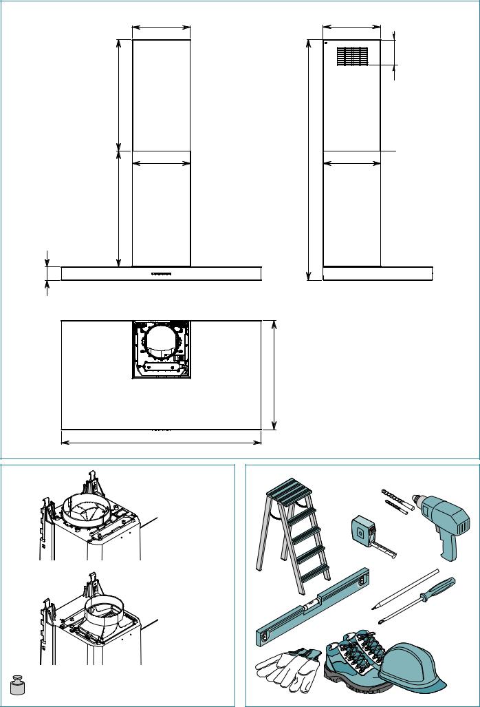
MAX 500
263
520
60
598/898/1198
800
M3/H
600
M3/H
PLANE 60: |
16 KG |
PLANE 90: |
18 KG |
PLANE 120: |
22 KG |
258
115
1080 |
260 |
|
|
MAX |
|
490
Ø8 MM |
Ø6 MM |
2

|
|
|
|
MM |
|
|
|
|
120 |
|
|
|
|
Ø |
|
|
|
Ø |
|
|
|
|
120 |
MM |
|
|
|
|
|
MIN.480 MM |
340 MM |
322 MM |
|
265MM 75MM |
MM |
|
|||
60 |
|
|
|
MM |
|
|
|
|
|
|
|
|
|
171 |
600
M3/H
|
|
|
|
|
|
|
MM |
|
|
|
|
|
|
|
150 |
|
|
|
|
|
|
|
|
Ø |
|
|
|
|
|
|
|
Ø |
|
|
|
|
|
|
|
|
|
|
|
|
|
|
|
|
|
|
|
|
|
|
|
|
|
|
150 |
MM |
||
|
|
|
|
|
|
|||
MIN.600 MM |
340 MM |
|
MM |
|
|
|
|
27MM |
|
|
|
|
|
||||
|
|
|
|
|
||||
|
|
|
|
|
||||
|
|
|
|
|
|
|||
MM |
|
|
|
|
|
|
|
265MM |
|
|
|
|
|
|
|||
60 |
|
|
|
|
|
|
|
|
|
|
|
|
|
|
|
|
|
|
|
|
|
|
|
|
|
|
800
M3/H
3

A |
|
|
|
|
B |
|
|
B |
|
2 |
|
|
|
|
|
|
|
|
322 MM |
|
|
|
|
H |
|
|
|
|
C |
|
|
|
|
|
|
|
60 MM |
|
|
|
|
|
630 MM (MIN) |
1 |
|
|
|
|
|
|
|
|
|
|
1 |
|
|
|
|
|
2 |
4 |
|
|
|
|
|
|
|
|
|
|
S |
|
|
|
|
MM |
|
V1 (X2) |
|
|
|
322 |
|
Ø 8 MM |
|
|
|
3 |
|
|
3 |
V2 (X2) |
|
|
|
|
|
|
|
|
|
800 |
600 |
|
800 |
|
M |
M3/H |
M3/H |
|
M3/H |
|
|
Ø 12 |
|
|
Ø 15 |
|
|
2 |
122MM |
|
150MM |
|
|
|
|
||
|
1 |
|
|
|
|
|
|
4 |
|
|
|
|
3 |
|
|
|
|
C |
|
|
|
|
D |
4
E |
|
|
|
|
|
H |
|
|
|
|
G |
1 |
|
|
|
|
|
|
|
|
|
2 |
|
|
|
|
V3 (X6) |
|
|
2 |
|
L |
5 |
L |
|
|
|
||
|
|
|
H |
|
|
|
|
|
H |
|
|
|
1 |
|
|
|
|
V5 |
|
|
|
|
(X2) |
|
|
|
4 |
|
Ø 6 |
|
|
|
|
|
|
|
|
|
Ø 6 MM |
|
|
Ø 6 |
|
|
|
|
|
|
V4 (X2) |
F |
|
|
|
|
|
|
5 |
|
|

G |
|
H |
1 |
2 |
2 |
|
|
2 |
|
|
1 |
I |
1 |
3 |
12V |
2 |
6
ISTRUZIONI DI SICUREZZA E AVVERTENZE
AVVERTENZE PER L'INSTALLATORE
TECNICA
Il lavoro di installazione deve essere eseguito, da installatori competenti e qualiicati, secondo quanto indicato nel presente libretto e rispettando le norme in vigore.
•Prima di installare la cappa controllare l'integrità e funzionalità di ogni sua parte: se si notano anomalie non procedere nell'installazione e contattare il Rivenditore.
•Nel caso sia stato riscontrato un difetto estetico la cappa NON deve essere installata; riporla nel suo imballo originale e contattare il Rivenditore. Una volta installata la cappa non sarà accettato alcun reclamo per difetti estetici.
•Durante l'installazione utilizzare sempre mezzi di protezione personale (es. scarpe antiinfortunistiche) ed adottare comportamente prudenti e corretti.
•Il kit di issaggio (viti, tasselli e stafe) fornito con la cappa è utilizzabile unicamente su pareti in muratura: se si rendesse necessario installare la cappa su pareti di materiale diverso, valutare altri sistemi di issaggio tenendo conto della resistenza del muro e del peso della cappa (indicato a pag. 2).
•Tenere presente che l’installazione con sistemi di issaggio diversi da quelli forniti o non conformi può comportare rischi di natura elettrica e di tenuta meccanica.
•Non modiicare la struttura elettrica, meccanica e funzionale dell'apparecchiatura.
•Non installare la cappa in ambienti esterni e non esporla ad agenti atmosferici (pioggia, vento, ecc...)
•Dopo l’installazione delle cappe in acciaio inox è necessario eseguire la pulizia della stessa per rimuovere i residui di collante del protettivo e le eventuali macchie di grasso e oli, che, se non rimosse, possono causare il deterioramento irreversibile della supericie della cappa. Per questa operazione il costruttore raccomanda l’utilizzo delle salviette in dotazione, disponibili anche in acquisto.
ELETTRICA
L’impianto elettrico al quale viene collegata la cappa deve essere a norma e obbligatoriamente munito di collegamento a terra secondo le norme di sicurezza del Paese di utilizzo; deve essere inoltre conforme alle normative Europee sull’antidisturbo radio.
•Prima di installare la cappa veriicare che la tensione di rete corrisponda a quella riportata dalla targhetta posta all’interno della cappa.
•La presa usata per il collegamento elettrico deve essere facilmente raggiungibile con l’apparecchiatura installata: se ciò non fosse possibile prevedere, in posizione accessibile, un interruttore generale per disconnettere la cappa al bisogno.
•Ogni eventuale modiica all’impianto elettrico che fosse necessaria per installare la cappa dovrà essere eseguita solo da un elettricista qualiicato.
•La lunghezza massima della vite di issaggio del camino (fornita dal fabbricante) è di 10 mm. L'utilizzo di viti non conformi con le presenti istruzioni può comportare rischi di natura elettrica.
•È pericoloso modiicare o tentare di modiicare le caratteristiche di questo apparecchio. In caso di malfunzionamenti dell’apparecchio, non tentare di risolvere da soli il problema ma contattare il Rivenditore o un Centro di Assistenza autorizzato per la riparazione.
•Durante l'installazione della cappa, disinserire l’apparecchio togliendo la spina o agendo sull’interruttore generale.
SICUREZZA SCARICO FUMI
•Non collegare l’apparecchio a condotti di scarico dei fumi prodotti dalla combustione (ad es. caldaie, caminetti, ecc...)
•Prima dell'installazione della cappa assicurarsi che siano rispettate tutte le normative vigenti sullo scarico dell’aria all’esterno del locale.
AVVERTENZE PER L'UTILIZZATORE
GENERALI
Queste avvertenze sono state redatte per la vostra sicurezza e per quella degli altri, Vi preghiamo, dunque, di leggere attentamente questo libretto in tutte le sue parti prima d’installare e di utilizzare l’apparecchio o di efettuare operazioni di pulizia sullo stesso.
•Il Costruttore declina ogni responsabilità per eventuali danni che possano, direttamente o indirettamente, essere causati a persone, cose ed animali domestici in conseguenza alla mancata osservanza delle avvertenze di sicurezza indicate in questo libretto.
•È molto importante che questo libretto istruzioni sia conservato insieme all’apparecchiatura per qualsiasi futura consultazione. Se l’apparecchio dovesse essere venduto o trasferito ad un’altra persona, assicurarsi che anche il libretto venga fornito, in modo che il nuovo utente possa essere messo al corrente del funzionamento della cappa e delle avvertenze relative.
•Il lavoro di installazione deve essere eseguito, da installatori competenti e qualiicati, secondo quanto indicato nel presente libretto e rispettando le norme in vigore.
•Se il cavo di alimentazione o altri componenti sono danneggiati la cappa NON deve essere utilizzata. Staccare la cappa dall'alimentazione elettrica e contattare il Rivenditore o un Centro Assistenza Tecnica autorizzato per la riparazione. Esigere parti di ricambio originali. Non tentare di efettuare da soli riparazioni o sostituzioni: gli interventi efettuati da persone non competenti e qualiicate possono provocare danni, anche molto gravi, a cose e/o persone non coperti da garanzia del Costruttore.
•Non modiicare la struttura elettrica, meccanica e funzionale dell'apparecchiatura. Ogni eventuale modiica all’impianto elettrico che fosse necessaria per installare la cappa dovrà essere eseguita solo da un elettricista qualiicato.
DESTINAZIONE D'USO
•L’apparecchio è destinato solo ed esclusivamente per l'aspirazione di fumi generati dalla cottura di alimenti su cucine domestiche, non professionali: qualsiasi utilizzo diverso da questo è improprio, può provocare danni a persone, cose ed animali domestici e solleva il Costruttore da qualsiasi responsabilità.
•L’apparecchio può essere utilizzato da bambini di età non inferiore a 8 anni e da persone con ridotte capacità isiche, sensoriali o mentali, o prive di esperienza o della necessaria conoscenza, purché sotto sorveglianza oppure dopo che le stesse abbiano ricevuto istruzioni relative all’uso sicuro dell’apparecchio e alla comprensione dei pericoli ad esso inerenti. I bambini non devono giocare con l’apparecchio. La pulizia e la manutenzione destinata ad essere efettuata dall’utilizzatore non deve essere efettuata da bambini senza sorveglianza.
ITALIANO
7

AVVERTENZE PER L'UTILIZZO E LA PULIZIA
•Prima di procedere a qualsiasi operazione di pulizia o di manutenzione, disinserire l’apparecchio togliendo la spina o agendo sull’interruttore generale.
•Non utilizzare la cappa con le mani bagnate o piedi scalzi.
•Quando l’apparecchio non viene usato, controllare sempre che tutte le parti elettriche, (luci, aspiratore), siano spente.
•Il peso massimo complessivo di eventuali oggetti posizionati o appesi (ove previsto) sulla cappa non deve superare 1,5 Kg.
•Controllare le friggitrici durante l’uso: I’olio surriscaldato potrebbe iniammarsi.
•Non accendere iamme libere sotto la cappa.
•Non preparare cibi alla iamma sotto la cappa.
•Non utilizzare mai la cappa senza i iltri metallici antigrasso; grasso e sporco in questo caso si depositerebbero nell'apparecchio compromettendone il funzionamento.
•Parti accessibili della cappa possono essere calde se utilizzate insieme con apparecchi di cottura.
•Non efettuare operazioni di pulizia quando parti della cappa sono ancora calde.
•Se la pulizia non è condotta secondo le modalità e i prodotti indicati nel presente libretto è possibile un rischio di incendio.
l’interruttore generale quando l’apparecchio non viene utilizzato per periodi prolungati di tempo
In caso di utilizzo contemporaneo di altre utenze (caldaie, stufe, caminetti, ecc.) alimentate a gas o con altri combustibili, provvedere ad una adeguata ventilazione del locale in cui avviene l’aspirazione dei fumi, secondo le norme vigenti.
AVVERTENZE IN CASO DI MALFUNZIONAMENTO
•Se il cavo di alimentazione o altri componenti sono danneggiati la cappa NON deve essere utilizzata. Staccare la cappa dall'alimentazione elettrica e contattare il Rivenditore o un Centro Assistenza Tecnica autorizzato per la riparazione. Esigere parti di ricambio originali. Non tentare di efettuare da soli riparazioni o sostituzioni: gli interventi efettuati da persone non competenti e qualiicate possono provocare danni, anche molto gravi, a cose e/o persone non coperti da garanzia del Costruttore.
Il Costruttore si riserva il diritto di apportare modiiche alle apparecchiature in qualsiasi momento e senza preavviso. La stampa, la traduzione e la riproduzione anche parziale del presente manuale s’intendono vincolate dall’autorizzazione del Costruttore.
Le informazioni tecniche, le rappresentazioni graiche e le speciiche presenti in questo manuale sono indicative e non divulgabili. La lingua di stesura del manuale è l’italiano, il Costruttore non si rende responsabile per eventuali errori di trascrizione o traduzione.
INSTALLAZIONE (parte riservata solo a personale qualiicato al montaggio della cappa)
 Prima di efettuare l'installazione della cappa, leggere attentamente il cap. "Istruzioni di sicurezza e avvertenze" a pag. 7.
CARATTERISTICHE TECNICHE
I dati tecnici dell'apparecchio sono riportati su delle targhette, posizionate all’interno della cappa.
POSIZIONAMENTO
La distanza minima fra la parte più alta dell'apparecchiatura per la cottura e la parte più bassa della cappa da cucina viene indicata in ig.
A a pag. 4.
In generale, quando la cappa da cucina è posta su un’apparecchiatura a gas, questa distanza deve essere almeno 65 cm (25,6"). Tuttavia sulla base di un’interpretazione della norma EN60335-2-31 del 11-07-2002 da parte del TC61 (subclause 7.12.1 meeting 15 agenda item 10.11), la distanza minima tra piano cottura e parte inferiore della cappa può essere ridotta alla quota riportata.
Se le istruzioni del piano di cottura a gas speciicano una distanza maggiore, bisogna tenerne conto. Non installare la cappa in ambienti esterni e non esporla ad agenti atmosferici (pioggia, vento, ecc...)
ALLACCIAMENTO ELETTRICO (parte riservata solo a personale qualiicato per l'allacciamento)
Prima di efettuare qualsiasi operazione sulla cappa scollegare l’apparecchio dalla rete elettrica.
Assicurarsi che non vengano scollegati o tagliati ili elettrici all’interno della cappa; nel caso si veriichino tali situazioni contattare il Centro Assistenza più vicino. Per l’allacciamento elettrico rivolgersi a personale qualiicato.
Il collegamento deve essere eseguito in conformità con le disposizioni di legge in vigore.
Prima di collegare l’apparecchio alla rete elettrica, controllare che:
•la tensione di rete corrisponda a quella riportata dalla targhetta posta all’interno della cappa;
•l’impianto elettrico sia a norma e possa sopportare il carico dell’apparecchio (vedere la targhetta caratteristiche tecniche posizionata all’interno della cappa);
•la spina e il cavo, una volta collegati, non entrino in contatto con parti calde aventi temperature superiori a 70 °C
•l’impianto di alimentazione sia munito di eicace e corretto collegamento di terra secondo le norme vigenti;
•la presa usata per il collegamento sia facilmente raggiungibile con l’apparecchiatura installata.
Alcuni tipi di apparecchi possono essere dotati di cavo senza spina; in questo caso, la spina da utilizzare deve essere dei tipo “normalizzato” tenendo conto che il ilo giallo-verde deve essere utilizzato per la messa a terra, il ilo blu deve essere utilizzato per il neutro e il ilo marrone deve essere utilizzato per la fase.
Montare sul cavo di alimentazione una spina adatta al carico e collegarla ad una adeguata spina di sicurezza.
Se un apparecchio isso non è provvisto di cavo di alimentazione e di spina, o di altro dispositivo che assicuri la disconnessione dalla rete, con una distanza di apertura dei contatti che consenta la disconnessione completa nelle condizioni della categoria di sovratensione III, tali dispositivi di disconnessione devono essere previsti nella rete di alimentazione conformemente alle regole di installazione.
Il cavo di terra giallo/verde non deve essere interrotto dall’interruttore.
Il Costruttore declina ogni responsabilità nel caso le norme di sicurezza non vengano rispettate.
8
SCARICO FUMI (parte riservata solo a personale qualiicato per il montaggio della cappa)
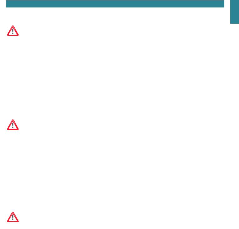
CAPPA IN VERSIONE AD EVACUAZIONE ESTERNA (ASPIRANTE)
In questa versione i fumi e i vapori della cucina vengono convogliati verso l’esterno attraverso un tubo di scarico. Il raccordo di uscita aria che sporge sulla parte superiore della cappa deve essere collegato con un tubo che conduce i fumi e i vapori in una uscita esterna.
Non collegare l’apparecchio a condotti di scarico dei fumi prodotti dalla combustione (ad es. caldaie, caminetti, ecc...) e rispettare obbligatoriamente le norme vigenti sullo scarico dell’aria all’esterno.
Il tubo di uscita dei fumi deve avere:
-un diametro non inferiore a quello del raccordo della cappa;
-una leggera inclinazione verso il basso (caduta) nei tratti orizzontali per evitare che, qualora si formasse condensa, questa reluisca nella cappa;
-il numero minimo indispensabile di curve;
-lunghezza minima indispensabile (tubazioni lunghe e con diverse curve potrebbero ridurre la capacità di aspirazione della cappa e innescare delle vibrazioni della valvola di non ritorno).
Se il tubo di uscita dei fumi passa attraverso ambienti freddi come soitte ecc., è possibile che si formi dell'acqua di condensa a causa di eventuali sbalzi di temperatura. In questo caso è necessario isolare la tubazione.
Nelle cappe dotate di motore 800m3/h viene fornita in dotazione una valvola di non ritorno la cui funzione è impedire scambi d'aria con l'esterno
quando la cappa non è in funzione: per il montaggio vedi istruzioni C a pag. 4.
Quando la cappa da cucina viene utilizzata contemporaneamente ad altri apparecchi che impiegano gas o altri combustibili, il locale di suiciente ventilazione secondo le norme vigenti.
In questa versione vanno tolti i iltri al carbone attivo; per la rimozione vedi istruzioni H a pag. 6.
Deviazione per la Germania: quando la cappa da cucina e apparecchi alimentati con energia diversa da quella elettrica sono in funzione simultaneamente, la pressione negativa nel locale non deve superare i 4 Pa (4 x 10⁻⁵ bar).
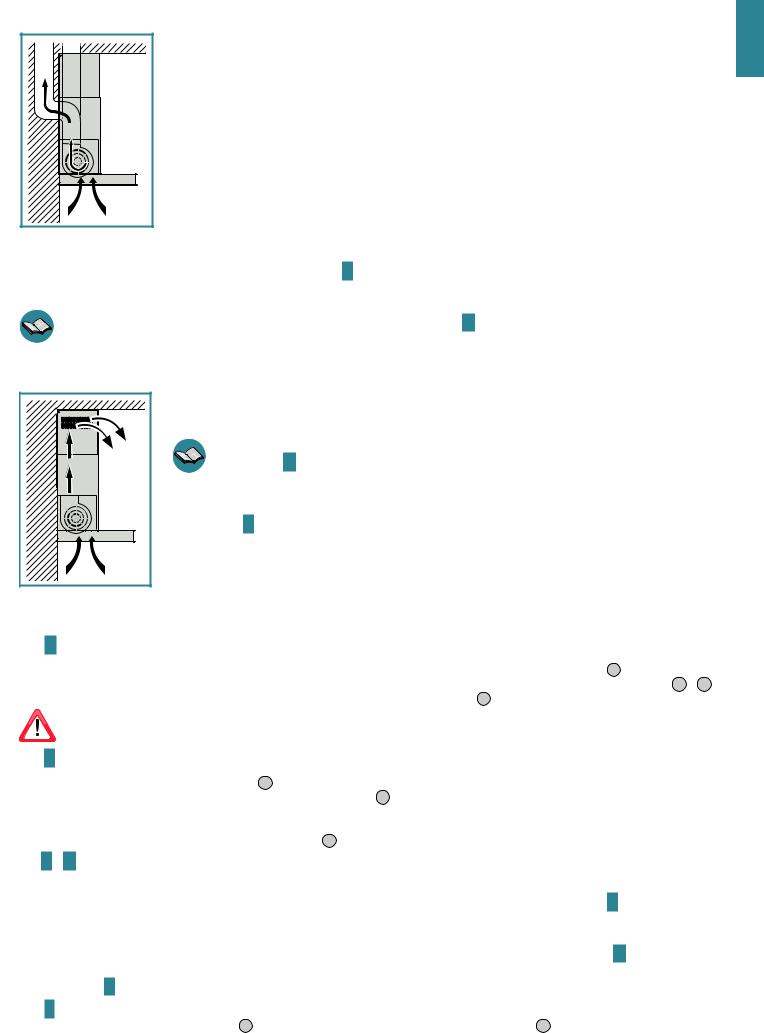
CAPPA IN VERSIONE A RICICLO INTERNO (FILTRANTE)
In questa versione l’aria passa attraverso i iltri al carbone attivo per essere puriicata e viene riciclata nell’ambiente
Controllare che i iltri al carbone attivo siano montati sulla cappa, in caso negativo applicarli come indicato nelle istruzioni H a pag. 6.
Se la cappa viene predisposta in versione iltrante la valvola di non ritorno non deve essere montata: rimuoverla se eventualmente presente sul raccordo di uscita aria del motore (efettuare l'operazione inversa a quanto descritto
nelle istruzioni C a pag. 4).
ISTRUZIONI DI MONTAGGIO (parte riservata solo a personale qualiicato per il montaggio della cappa)
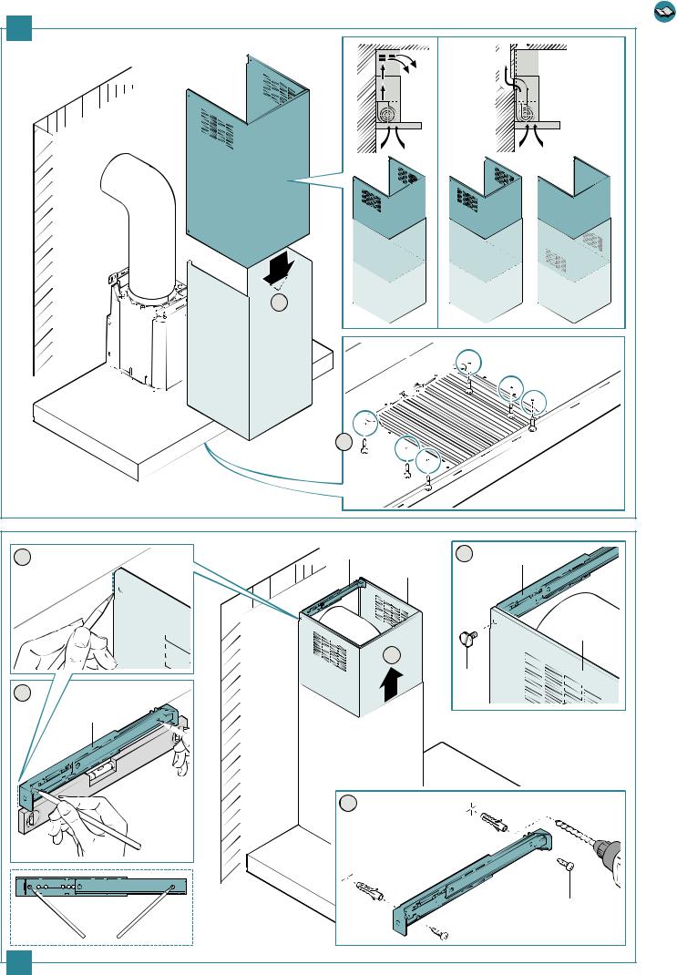
Fase A pag. 4
• Appoggiare alla parete di installazione la barra di sostegno (S), ad una altezza (H) dal piano cottura indicata in igura (Fig. 1 ).
• Controllare con una bolla di livello l’allineamento orizzontale e segnare alle estremità della barra di sostegno n° 2 punti di foratura (Fig. 2 - 3 ).
• Forare, inserire n° 2 tasselli ad espansione ø 8mm e issare la barra con le relative viti (V1) (Fig. 4 ).
Il kit di issaggio (viti, tasselli e stafe) fornito con la cappa è utilizzabile unicamente su pareti in muratura: se si rendesse necessario installare la cappa su pareti di materiale diverso, valutare altri sistemi di issaggio tenendo conto della resistenza del muro e del peso della
cappa (indicato a pag. 2).
Fase B pag. 4
•Agganciare la cappa alla barra di sostegno (Fig. 1 ).
•Regolare l’allineamento della cappa tramite le viti delle attaccaglie (Fig. 2 ). La vite superiore (B) regola la distanza dalla parete, quella inferiore (C) lo scorrimento verticale.
•Per evitare lo sganciamento della cappa dovuto ad una pressione sottostante, issarla alla parete con dei tasselli ad espansione e relative viti (V2) utilizzando gli appositi fori presenti sul retro della cappa (Fig. 3 ).
Fasi C e D pag. 4
CAPPA IN VERSIONE AD EVACUAZIONE ESTERNA (ASPIRANTE)
•Solo per versione con motore 800m3/h: se lo si desidera, installare la valvola di non ritorno (M) come indicato in igura C.
•Collegare il raccordo di uscita aria della cappa allo scarico esterno con una tubazione idonea.
CAPPA IN VERSIONE A RICICLO INTERNO (FILTRANTE)
•Controllare che i iltri al carbone attivo siano montati sulla cappa, in caso negativo applicarli come indicato nelle istruzioni H a pag. 6.
•Se installata, rimuovere la valvola di non ritorno montata sul raccordo di uscita aria della cappa (efettuare l'operazione inversa a quanto descritto nelle istruzioni C a pag. 4).
Fase E pag. 5
• Inserire la prolunga (H) nel camino (G) (Fig. 1 ) e issare l’assieme al corpo cappa mediante le viti (V3)(Fig. 2 ).
ITALIANO
9

•Nel caso di versione ad evacuazione esterna (aspirante) è possibile inserire la prolunga (H) con le asole verso il basso in modo da renderle non visibili qualora le quote di installazione lo permettano.
Fase F pag. 5
•Fare scorrere la prolunga (H) ino a raggiungere l’altezza desiderata (Fig. 1 ).
•Seguendo quanto indicato nella ig. 2 , tracciare sulla parete una linea che servirà per posizionare correttamente la stafa (L).
•Posizionare a parete la stafa (L) seguendo la linea tracciata, controllare con una bolla di livello l’allineamento orizzontale e segnare alle estremità n°2 punti di foratura (Fig. 3 .
•Forare, inserire n° 2 tasselli ad espansione ø 6mm e issare la stafa (L) con le relative viti (V4) (Fig. 4 ).
•Avvitare con le viti (V5) la prolunga (H) alla stafa (L) (Fig. 5 ).
•Alimentare elettricamente la cappa rispettando le norme vigenti.
FUNZIONAMENTO
QUANDO ACCENDERE E SPEGNERE LA CAPPA?
Accendere la cappa almeno un minuto prima di iniziare a cucinare: questo favorirà un lusso d’aria per convogliare fumi e vapori verso la supericie di aspirazione. Al termine della cottura lasciare in funzione la cappa ino alla completa aspirazione di tutti i vapori e gli odori: eventualmente, attraverso la funzione Timer, è possibile impostare l'autospegnimento della cappa dopo 15 minuti di funzionamento.
QUALE VELOCITÀ SCEGLIERE?
La prima velocità si utilizza per mantenere l’aria pulita con bassi consumi di energia elettrica, la seconda velocità si utilizza nelle condizioni normali, la terza velocità si utilizza in presenza di forti odori e vapori.
QUANDO LAVARE O CAMBIARE I FILTRI?
La cappa monta due diversi tipi di iltri: quelli metallici (lavabili) e quelli al carbone attivo (non lavabili). I primi devono essere puliti ogni 30 ore di utilizzo (nella versione con pulsantiera elettronica la luce rossa 

 indica che è il momento di lavarli), i secondi vanno sostituiti circa ogni 3-4 mesi a seconda dell'utilizzo della cappa. Per ulteriori informazioni leggere il cap. "Manutenzione" a pag. 11.
UTILIZZO PULSANTIERA MECCANICA
|
OFF |
1 |
|
2 |
3 |
600 |
|
|
|
|
|
|
|
|
M3/H |
|
|
|
|
|
|
||
|
|
|
|
|
|
||
|
Pulsante luce |
|
|
1 |
Pulsante 1: Premendo il tasto (tasto rientrato) si avvia o si impo- |
||
|
|
|
sta il motore alla velocità minima |
|
|||
|
Pemendo il tasto si accende (tasto rientrato) o si spegne (tasto |
|
|
|
|
||
|
|
|
|
|
|
|
|
|
|
|
|
Pulsante 2: Premendo il tasto (tasto rientrato) si avvia o si impo- |
|||
|
sporgente) la luce della cappa |
|
|
2 |
|||
|
|
|
sta il motore alla velocità media |
|
|||
|
|
|
|
|
|
||
|
|
|
|
|
|
||
OFF |
Pulsante OFF |
|
|
3 |
Pulsante 3: Premendo il tasto (tasto rientrato) si avvia o si impo- |
||
|
Premendo il tasto si spegne il motore |
|
|
|
sta il motore alla velocità massima |
|
|
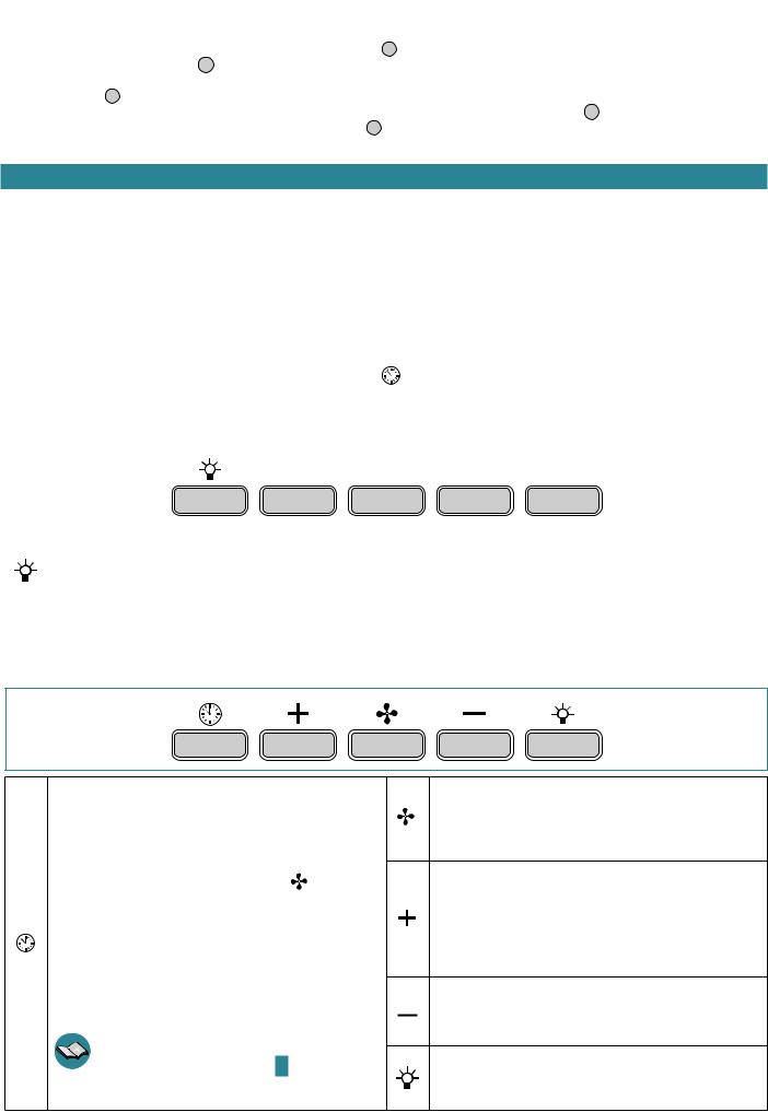
UTILIZZO PULSANTIERA ELETTRONICA
800
M3/H
Timer/Allarme iltri
La pressione del tasto, con motore attivo a velocità qualsiasi, attiva la funzione Timer: tale funzione determina l’autospe gnimento della cappa dopo 15 minuti di funzionamento. L'attivazione della funzione è segnalata dalla luce ROSSA lampeggiante.
Con la funzione Timer attiva, la cappa può essere comunque spenta dall’utente in qualsiasi momento premendo il
: la funzione verrà automaticamente disattivata e si spegnerà la luce ROSSA. Se viene variata la velocità con la funzione Timer attiva quest'ultima verrà automaticamente disattivata.
L'accensione della luce ROSSA issa indica invece l’allarme iltro grassi: questo allarme avvisa che è il momento di lavare i iltri metallici antigrasso (l'allarme si attiva dopo circa 30 ore di utilizzo). Dopo la pulizia dei iltri, per disattivare l' allarme ed azcontatori tenere premuto il tasto per 3 secondi.
Per lo smontaggio e montaggio dei iltri metallici antigrasso vedi istruzioni al disegno G a pag. 6.
Pulsante modalità (ON/OFF)
Premendo il tasto si accende (o spegne) il motore cappa: quest'ultimo si avvia con l’ultima velocità selezionata prima del precedente spegnimento (funzione velocità desiderata). Se si desidera utilizzare una velocità diversa, impostarla utilizzando i tasti + e -.
Pulsante +
Premendo il tasto si incrementa la velocità del motore. Le velocità 1, 2 e 3 sono visualizzate dal n° di led accesi escluso led luce e timer.
Nelle versioni a 4 velocità il tasto + presenta una luce intermittente: la 4° velocità o intensiva è temporizzata e dopo circa 7 minuti il motore passa automaticamente in 3° velocità.
Pulsante -
Premendo il tasto si riduce la velocità del motore. Le velocità 1, 2 e 3 sono visualizzate dal n° di led accesi escluso led luce e timer.
Pulsante luce
ON: luce accesa (pulsante illuminato) OFF: luce spenta
10
ILLUMINAZIONE
La cappa è dotata di illuminazione tramite faretti led ad alta eicienza, basso consumo e durata molto elevata in condizioni di normale utilizzo.
Nel caso si rendesse necessaria la sostituzione del faretto led, procedere come in igura I a pag. 6.
MANUTENZIONE
Prima di procedere a qualsiasi operazione di pulizia o di manutenzione, disinserire l’apparecchio togliendo la spina o agendo sull’interruttore generale.
Una costante manutenzione garantisce un buon funzionamento ed un buon rendimento nel tempo.
Particolari attenzioni vanno rivolte ai iltri metallici antigrasso ed ai iltri al carbone attivo; infatti la pulizia frequente dei iltri e dei loro supporti garantisce che sulla cappa non si accumulino grassi che sono pericolosi per la facilità di incendio.
PULIZIA ESTERNA
Si raccomanda di pulire le superici esterne della cappa almeno ogni 15 giorni per evitare che le sostanze oleose o grasse possano intaccarle. Per la pulizia della cappa, realizzata in acciaio inox spazzolato, il Costruttore consiglia l'utilizzo delle salviette "Magic Steel" che si possono anche ordinare on-line sul sito www.e-falmec.com. In alternativa la pulizia va eseguita usando un panno umido leggermente imbevuto di detersivo neutro liquido
denaturato. Terminare la pulizia con un accurato risciacquo e asciugatura con panni morbidi.
Non utilizzare troppa acqua in prossimità della pulsantiera e dei dispositivi di illuminazione per evitare che l'umidità raggiunga parti elettroniche.
Non si devono utilizzare detergenti contenenti sostanze abrasive, acide o corrosive e panni con superici ruvide: conseguenza diretta del non rispetto di tali avvertenze sarà il deterioramento irreversibile della supericie della cappa.
Il Costruttore declina ogni responsabilità qualora non vengano rispettate tali istruzioni.
PULIZIA PARTI INTERNE
É vietata la pulizia di parti elettriche o parti relative al motore all’interno della cappa, con liquidi o solventi.
Non usare prodotti contenenti abrasivi.
Efettuare tutte queste operazioni scollegando preventivamente l’apparecchio dalla rete elettrica.
FILTRI METALLICI ANTIGRASSO
I iltri metallici antigrasso hanno la funzione di trattenere le particelle grasse in sospensione: queste ultime, depositate sui iltri, alimentano eventuali iamme sprigionate durante la cottura, generano odori poco gradevoli e compromettono il passaggio dell'aria riducendo la capacità di aspirazione della cappa.
Per questi motivi si consiglia di lavare frequentemente i iltri metallici (almeno ogni mese) lasciandoli in ammollo per circa 1 ora in acqua bollente e detersivo per piatti evitando di piegarli. Non usare detergenti corrosivi, acidi o alcalini. Risciacquarli con cura e attendere che siano ben asciutti prima di rimontarli.
Il lavaggio in lavastoviglie è permesso ma potrebbe creare imbrunimenti al materiale dei iltri: per ridurre questo inconveniente utilizzare lavaggi a basse temperature (55°C max.).
 Per l’estrazione dei iltri metallici antigrasso agire sulla maniglia (vedi istruzioni G a pag. 6). Per l’inserimento invertire l’operazione.
FILTRI AL CARBONE ATTIVO
I iltri al carbone attivo hanno la funzione di trattenere gli odori presenti nel lusso d’aria che li attraversa: l’aria depurata per successivi passaggi attraverso i iltri viene rimessa nell’ambiente cucina.
l iltri al carbone attivo non possono essere lavati e vanno sostituiti mediamente ogni 3-4 mesi (dipende dalla frequenza di utilizzo della cappa).
Smaltire i iltri al carbone attivo secondo le disposizioni in vigore nel Paese di utilizzo.
Per ordinare i nuovi iltri al carbone attivo rivolgersi al distributore/rivenditore o ad un Centro Assistenza autorizzato. I iltri al carbone ed eventuali accessori si possono anche ordinare on-line sul sito www.e-falmec.com
Per la sostituzione dei iltri al carbone attivo, rimuovere i iltri metallici antigrasso (vedi istruzioni G a pag. 6) e seguire le istruzioni H a pag. 6.
ITALIANO
11

 SMALTIMENTO A FINE VITA
Il simbolo del cestino barrato riportato sull’apparecchiatura in suo possesso indica che il prodotto è un RAEE, cioè un “Riiuto derivante dalle Apparecchiature Elettriche ed Elettroniche” e pertanto non deve essere gettato nella spazzatura indiferenziata (cioè insieme ai “riiuti urbani misti”), ma deve essere gestito separatamente così da essere sottoposto ad apposite operazioni per il suo riutilizzo, oppure a uno speciico trattamento, per rimuovere e smaltire in modo sicuro le eventuali sostanze dannose per l’ambiente ed estrarre le materie prime che possono essere riciclate.Lo smaltimento corretto di questo prodotto contribuirà a salvare preziose risorse ed evitare potenziali efetti negativi per la salute umana e per l’ambiente, che potrebbero essere causati da uno smaltimento inappropriato dei riiuti. Vi preghiamo di contattare le autorità locali per ulteriori dettagli sul punto di smaltimento designato più vicino. Potrebbero venire applicate delle penali per lo smaltimento scorretto di questi riiuti in conformità alla legislazione nazionale.
INFORMAZIONI SULLO SMALTIMENTO IN ITALIA
In Italia le apparecchiature RAEE devono perciò essere consegnate:
-ai Centri di Raccolta (chiamati anche isole ecologiche o piattaforme ecologiche) allestiti dai Comuni o dalle Società di igiene urbana (in molte località viene anche efettuato il servizio di ritiro a domicilio delle apparecchiature RAEE ingombranti);
- al negozio presso il quale si acquista una nuova apparecchiatura, che è tenuto a ritirarle gratuitamente (ritiro “uno contro uno”);
-ad un negozio qualunque*, che è tenuto a ritirarle gratuitamente e senza obbligo di acquisto (ritiro “uno contro zero”). In questo caso:
1) l’apparecchiatura RAEE, per poter essere riconsegnata, deve avere “piccolissime dimensioni” (altezza, profondità e larghezza minori di 25 cm); *2) il negozio al quale viene riconsegnata l’apparecchiatura RAEE deve avere una supericie di vendita superiore a 400 mq.
INFORMAZIONI SULLO SMALTIMENTO IN NAZIONI DELL'UNIONE EUROPEA
La Direttiva comunitaria sulle apparecchiature RAEE è stata recepita in modo diverso da ciascuna nazione, pertanto se si desidera smaltire questa apparecchiatura suggeriamo di contattare le autorità locali o il Rivenditore per chiedere il metodo corretto di smaltimento.
INFORMAZIONI SULLO SMALTIMENTO IN NAZIONI NON APPARTENENTI ALL'UNIONE EUROPEA
Il simbolo del cestino barrato è valido solamente nell’Unione Europea: se si desidera smaltire questa apparecchiatura in altri Paesi suggeriamo di contattare le autorità locali o il Rivenditore per chiedere il metodo corretto di smaltimento.
GARANZIA (solo per l'Italia)
La sua nuova apparecchiatura è coperta da garanzia. Le condizioni di garanzia sono riportate per esteso nel paragrafo successivo.
La casa costruttrice non risponde delle possibili inesattezze, imputabili ad errori di stampa o di trascrizione, contenute nel presente libretto. Si riserva di apportare ai propri prodotti quelle modiiche che ritenesse necessarie o utili, anche nell’interesse dell’utenza, senza pregiudicare le caratteristiche essenziali di funzionalità e di sicurezza.
CONDIZIONI DI GARANZIA (solo per l'Italia)
IMPORTANTE!
La presente garanzia è valida solo per l’Italia (Guarantee conditions are valid only for Italy).
DECRETO LEGISLATIVO DEL 30/06/2003 N. 196 - ART. 7
Codice in materia di protezione dei dati personali.
1.L’interessato ha diritto di ottenere la conferma dell’esistenza o meno di dati personali che lo riguardano, anche se non ancora registrati, e la loro comunicazione in forma intelleggibile.
2.L’interessato ha diritto di ottenere l’indicazione:
a)dell’origine dei dati personali;
b)delle inalità e modalità del trattamento;
c)della logica applicata in caso di trattamento efettuato con l’ausilio di strumenti elettronici;
d)degli estremi identiicativi del titolare, dei responsabili e del rappresentante designato ai sensi dell’articolo 5, comma 2;
e)dei soggetti o delle categorie di soggetti ai quali i dati personali possono essere comunicati o che possono venirne a conoscenza in qualità di rappresentante designato nel territorio dello Stato, di responsabili o incaricati.
3. L’interessato ha diritto di ottenere:
a)l’aggiornamento, la rettiicazione ovvero, quando vi ha interesse, l’integrazione dei dati;
b)la cancellazione, la trasformazione in forma anonima o il blocco dei dati trattati in violazione di legge, compresi quelli di cui non è necessaria la conservazione in relazione agli scopi per i quali i dati sono stati raccolti o successivamente trattati;
c)l’attestazione che le operazioni di cui alle lettere a) e b) sono state portate a conoscenza, anche per quanto riguarda il loro contenuto , di coloro ai quali i dati sono stati comunicati o difusi, eccettuato il caso in cui tale adempimento si rileva impossibile o comporta un impiego di mezzi manifestamente sproporzionato rispetto al diritto tutelato.
4. L’interessato ha diritto di opporsi, in tutto o in parte:
a)per motivi legittimi al trattamento dei dati personali che lo riguardano, ancorché pertinenti allo scopo della, raccolta;
b)al trattamento di dati personali che lo riguardano a ini di invio di materiale pubblicitario o di vendita diretta o per il compimento di ricerche di mercato o di comunicazione commerciale.
Titolare del trattamento dei dati è Falmec S.P.A. - Via dell’Artigianato, 42 - Vittorio Veneto (TV).
CONDIZIONI DI GARANZIA
•L’apparecchio è garantito dalla Casa costruttrice Falmec S.p.A (www.falmec.com) per un periodo di 24 mesi dalla data del suo acquisto comprovata da ricevuta iscale o altro documento reso iscalmente obbligatorio.
•La garanzia sarà prestata con la sostituzione o riparazione gratuita delle parti che risultino difettose per vizi delle stesse imputabili a Falmec S.p.A..
•Non sono coperte dalla presente garanzia tutte le parti che dovessero risultare difettose, danneggiate e/o viziate a causa di uso improprio dell’apparecchio, di negligenza o trascuratezza nell’uso (mancata osservanza delle istruzioni per il funzionamento dell’apparecchio), di inesatta installazione, di mancata ovvero errata manutenzione, di manutenzioni operate da personale non autorizzato, di danni da trasporto, ovvero per
12

circostanze non riferibili a difetti di funzionamento imputabili a Falmec S.p.A. e/o comunque direttamente imputabili alla Casa costruttrice. Si precisa inoltre che non rientrano nelle prestazioni in garanzia gli interventi inerenti l’installazione e l’allacciamento agli impianti elettrici e/o di alimentazione.
•Vengono peraltro esclusi dalla presente garanzia i componenti dell’apparecchio soggetti ad usura, quali speciicatamente ma non esaustivamente: lampadine di varie tipologie, iltri metallici, iltri carbone, ecc.
•La Casa costruttrice declina ogni responsabilità per eventuali danni che possono, direttamente o indirettamente, essere causati a persone, cose ed animali domestici in conseguenza alla mancanza di tutte le prescrizioni indicate nell’apposito libretto istruzioni e concernenti, specialmente, le avvertenze in tema di installazione, uso e manutenzione dell’apparecchio.
•Trascorsi i 24 mesi, l’apparecchio non sarà più coperto da garanzia e l’assistenza verrà prestata addebitando le parti sostituite, le spese di manodopera e di trasporto dei personale e dei materiali, secondo le tarife vigenti in possesso dei personale dei Servizio Assistenza Tecnica autorizzato dalla Casa costruttrice. In presenza di un intervento efettuato presso un Centro Assistenza Tecnica autorizzato, l’apparecchio vi sarà recapitato a spese e rischio dell’utente.
•La presente garanzia è valida per la fornitura ed installazione dell’apparecchio avvenuta nel solo territorio italiano.
Titolare del trattamento dei dati è Falmec S.P.A. - Via dell’Artigianato, 42 - Vittorio Veneto (TV).
CERTIFICATO DI GARANZIA (SOLO PER ITALIA - DA CONSERVARE)
Questo certiicato di garanzia non deve essere spedito, ma conservato con la ricevuta iscale, o altro documento reso iscalmente obbligatorio, che comprovi la data d’acquisto della cappa. In caso necessiti intervenire per anomalie di funzionamento, si prega di contattare un Centro di Assistenza Tecnica autorizzato, tenenendo a portata di mano i dati sotto indicati:
Matricola/Serial Number (vedere ultima pagina libretto o targhetta dei dati tecnici posta all'interno della cappa):
È ASSOLUTAMENTE NECESSARIO INDICARE IL NUMERO MATRICOLA DELLA CAPPA.
Questo apparecchio viene garantito per 2 anni dalla data di acquisto contro difetti di materiale e/o di fabbricazione.
Questo certiicato è valido e operante solo se conservato assieme alla ricevuta iscale o altro documento reso iscalmente obbligatorio.
Rivenditore:
Città:
Data d’acquisto:
ITALIANO
13

SAFETY INSTRUCTIONS AND WARNINGS
INSTALLATION WARNINGS
SAFETY
Installation operations are to be carried out by skilled and qualiied installers in accordance with the instructions in this booklet and in compliance with the regulations in force.
•Before installing the hood, check the integrity and function of each part. Should anomalies be noted, do not proceed with installation and contact the Dealer.
•Do NOT install the hood if an aesthetic defect has been detected. Put it back into its original package and contact the dealer. No claim can be made for aesthetic defects once the hood has been installed.
•During installation, always use personal protective equipment (e.g. accident-prevention shoes) and adopt prudent and proper conduct.
•The ixing kit (screws, plugs, and brackets) supplied with the hood can only be used on masonry walls: should it be necessary to install the hood onto walls in a diferent material, assess other ixing systems keeping the wall resistance and weight of the hood in mind (indicated on page 2).
•Keep in mind that installations with diferent types of ixing systems from those supplied, or which are not compliant, can cause electrical and mechanical seal danger.
•Do not modify the electrical, mechanical and functional structure of the equipment.
•Do the install the hood outdoors and do not expose it to atmospheric agents (rain, wind, etc.).
•After the stainless steel hood has been installed, it will need to be cleaned to remove any residues from the protection adhesive as well as any grease and oil stains which, if not removed, can cause irreversible damage to the hood surface. To do so the manufacturer recommends using the supplied moist wipes, which are also available sold separately.
SAFETY
The electrical system to which the hood is to be connected must be according to standard and compulsorily supplied with earthed connection in compliance with safety regulations in the country of use. It must also comply with European standards regarding radio antistatic properties.
•Before installing the hood, check that the electrical mains power supply corresponds with what is reported on the identiication plate located inside the hood.
•The socket used to connect the installed equipment to the electrical power supply must be within reach: if this is not possible, install a mains switch in an accessible position in order to disconnect the hood when required.
•Any changes to the electrical system required to install the hood must be carried out by a qualiied electrician.
•The maximum length of the lue ixing screws (supplied by the manufacturer) must be 10 mm. Use of non-compliant screws with these instructions can lead to danger of an electrical nature.
•It is dangerous to change, or try to change, the features of this equipment. Do not try to solve the problem yourself in the event of equipment malfunction, but contact the Dealer or an authorised Servicing Department for repairs.
•When installing the hood, disconnect the equipment by removing the plug or switching of the main switch.
FUMES DISCHARGE SAFETY
•Do not connect the equipment to discharge pipes of fumes produced from combustion (for example boilers, ireplaces, etc.)
•Before installing the hood, ensure that all standards in force regarding discharge of air out of the room have been complied with.
USER WARNINGS
WARNINGS
These warnings have been drawn up for your personal safety and those of others. You are therefore kindly asked to read the booklet carefully in its entirety before installing and using the equipment or carrying out cleaning operations.
•The Manufacturer declines all responsibility for any damage caused directly, or indirectly, to persons, things and pets as a consequence of failing to comply with the safety warnings indicated in this booklet.
•It is imperative that this instructions booklet is kept together with the equipment for any future consultation. If the equipment is sold or transferred to another person, make sure that the booklet is also supplied so that the new user can be made aware of the hood's operation and relative warnings.
•Installation operations are to be carried out by a skilled and qualiied installer in accordance with the instructions in this booklet and in compliance with the regulations in force.
•DO NOT use the hood if the power supply cable or other components are damaged. Disconnect the hood from the electrical power supply and contact the Dealer or an authorised Servicing Department for repairs. Insist on original spare parts. Do not personally try to carry out repairs or replacements. Interventions carried out by incompetent and unauthorised persons can cause damage, even serious, to things and/or persons not covered by the Manufacturer's warranty.
•Do not modify the electrical, mechanical and functional structure of the equipment. Any changes to the electrical system required to install the hood must be carried out by a qualiied electrician.
INTENDED USE
•The equipment is solely intended to be used to extract fumes generated from cooking food in non-professional domestic kitchens: any other use is improper, can cause damage to persons, things and pets and exempts the Manufacturer from any liability.
•The equipment can be used by children above the age of 8 and by persons with reduced physical, sensory and mental abilities, or with no experience or knowledge, as long as they do so under supervision or after having received relative instructions regarding safe use of the equipment and understanding of the dangers connected to it. Children are not to play with the equipment. Cleaning and maintenance operations intended for the user must not be carried out by children without supervision.
14
USE AND CLEANING WARNINGS |
|
|
• Before cleaning or carrying out maintenance operations, disconnect the equipment by removing the plug or switching of the main |
|
|
|
switch. |
|
• Do not use the hood with wet hands or bare feet. |
|
|
• Always check that all electrical parts (lights, extractor fan) are of when the equipment is not used. |
|
|
• The maximum overall weight of any objects placed or hung (if applicable) on the hood must not exceed 1.5 Kg. |
ENGLISH |
|
• |
Never use the hood without the metal anti-grease ilters: in this case, grease and dirt will deposit in the equipment and compromise its operation. |
|
• |
Check the deep-fryers during use: Overheated oil can catch ire. |
|
• Do not light naked lames under the hood.
• Do not lambé foods under the hood.
• Accessible parts of the hood can be hot if used together with cooking appliances.
• Do not carry out any cleaning operations when parts of the hood are still hot.
• There can be a risk of ire if cleaning is not carried out according to the methods and products indicated in this booklet. the main switch when the equipment is not used for long periods of time.
If other appliances that use gas or other fuels are being used at the same time (boiler, stove, ireplaces, etc.), make sure the room where the fumes are extracted is well-ventilated, in compliance with the current regulations.
WARNINGS IN CASE OF MALFUNCTION
•DO NOT use the hood if the power supply cable or other components are damaged. Disconnect the hood from the electrical power supply and contact the Dealer or an authorised Servicing Department for repairs. Insist on original spare parts. Do not personally try to carry out repairs or replacements. Interventions carried out by incompetent and unauthorised persons can cause damage, even serious, to things and/or persons not covered by the Manufacturer's warranty.
The manufacturer reserves the right to make changes to the equipment at any time and without prior notice. Printing, translation and reproduction, even partial, of this manual are bound by the Manufacturer's authorisation.
Technical information, graphic representations and speciications in this manual are for information purposes and cannot be divulged. This manual is written in Italian. The Manufacturer is not responsible for any transcription or translation errors.
INSTALLATION (only intended for personnel qualiied to install the hood)
Before installing the hood, carefully read Chap. "Safety instructions and warnings" on page 14.
TECHNICAL FEATURES
The technical speciications are reported on the identiication plate located inside the hood.
POSITIONING
The minimum distance between the highest part of the equipment for cooking and the lowest part of the hood is indicated in Fig. A on page 4.
Generally, when the hood is placed on gas cookers, this distance must be at least 65 cm (25.6"). However, according to an interpretation of standard EN60335-2-31 dated 11-07-2002 of TC61 (sub-clause 7.12.1 meeting 15 agenda item 10.11), the minimum distance between the cooker and lower part of the hood can be reduced to the reported quota.
Should the instructions for the gas cooker specify a greater distance, take this into consideration. Do not install the hood outdoors and do not expose it to atmospheric agents (rain, wind, etc.).
ELECTRICAL CONNECTION (only intended for personnel qualiied to install the hood)
Disconnect the equipment from electrical mains power supply before carrying out any operations on the hood.
Make sure that the wires inside the hood are not disconnected or cut. Should this occur, contact your nearest Servicing Department. Refer to qualiied personnel for electrical connections.
Connection must be carried out in compliance with the provisions of law in force.
Before connecting the equipment to the electrical mains power supply, check that:
•voltage supply corresponds with what is reported on the identiication plate located inside the hood;
•the electrical system is compliant and can withstand the load of the equipment (refer to the technical speciications on the identiication plate located inside the hood);
•once connected, the plug and cable do not come into contact with hot parts having temperatures that exceed 70°C
•the power supply system is efectively and properly connected to earth in compliance with regulations in force.
•the socket outlet to connect the installed equipment is within reach.
Some types of equipment can be equipped with a cable without a plug; in this case, the type of plug to use is a "standardised" one, keeping in mind that the yellow-green wire must be used for earthing, the blue wire must be used for neutral, and the brown wire must be used for the phase.. The power supply cable must be assembled with a plug suitable for the load and connected to an adequate safety plug.
If the ixed equipment is not provided with a power supply cable and plug, or any other device that ensures disconnection from the electrical mains, with an opening gap of the contacts that enables total disconnection in overvoltage category III conditions, said disconnection devices must be provided in the mains power supply in compliance with installation regulations.
The yellow/green earth cable must not be cut of by the switch.
The Manufacturer declines all responsibility for failure to comply with the safety regulations.
15

FUMES DISCHARGE (only intended for personnel qualiied to assemble the hood)
EXTERNAL EXHAUST HOOD VERSION (SUCTION)
In this version, the kitchen fumes and vapours are conveyed outside through an exhaust pipe.
The air outlet itting that extends from the upper part of the hood must be connected with the pipe that conducts the fumes and vapours to an external output.
Do not connect the equipment to discharge pipes of fumes produced from combustion (for example boilers, ireplaces, etc) and you are to comply with the regulations in force regarding external air discharge.
The fumes outlet pipe must have:
-a diameter not less than that of the hood itting;
-a slight slope downwards (drop) in the horizontal sections to prevent any formation of condensation from lowing back to the hood;
-the minimum required number of bends;
-minimum required length (long pipes with various bends can reduce suction performance of the hood and trigger vibrations of the check valve).
If the fumes outlet pipe passes through cold environments such as attics, etc., it is possible that water condensation forms due to sudden changes in temperature. In this case, you are required to insulate the pipes.
The hood supplied with an 800 m3/h motor is equipped with a check valve whose function is to prevent external air exchange when the hood is not
operating: refer to the instructions C on page 4 for assembly.
When the kitchen hood is used simultaneously with other appliances that use gas or other fuels, the room must have suicient ventilaaccordance with regulations in force.
The active carbon ilters in this version are to be removed. Refer to the instructions H on page 6 for removal.
Deviation for Germany: when the kitchen hood is used at the same time as appliances that are powered by energy other than electricity, the negative pressure in the room must not exceed 4 Pa (4 x 10⁻⁵ bar).
HOOD VERSION WITH INTERNAL RECIRCULATION (FILTERING)
In this model, air passes through the active carbon ilters to be puriied and is then recycled into the kitchen envi-
.
Check that the active carbon ilters are assembled onto the hood, if not, install them as indicated in the instructions H on page 6.
If the hood is set up with a iltering version, the check valve must not be assembled: remove it if it is on the air outlet itting of the motor (carry out operations described in the instructions C on page 4 in reverse order).
ASSEMBLY INSTRUCTIONS (only intended for personnel qualiied to assemble the hood)
Phase A page 4
•Place the support bar (S) on the installation wall at a height (H) from the cooker indicated in the igure (Fig. 1 ).
•Use a spirit level to check the horizontal alignment and draw 2 marks at each end of the support bar, this is where the holes will be drilled (Fig.
2 - 3 ).
• Drill the holes, insert 2 expansion plugs (ø 8mm) and fasten the bar with the relative screws (V1) (Fig. 4 ).
The ixing kit (screws, plugs, and brackets) supplied with the hood can only be used on masonry walls: should it be necessary to install the hood onto walls in a diferent material, assess other ixing systems keeping the wall resistance and weight of the hood in mind
(indicated on page 2).
Phase B page 4
•Hook the hood onto the support bar (Fig. 1 ).
•Adjust the alignment of the hood by using the ixing screws (Fig. 2 ). The upper screw (B) adjusts the distance from the wall, the lower one (C) adjusts vertical scrolling.
•To prevent the hood from falling due to a pressure below, fasten it to the wall with expansion plugs and relative screws (V2) using the appropriate holes on the back of the hood (Fig. 3 ).
Phase C and D page 4
EXTERNAL EXHAUST HOOD VERSION (SUCTION)
• Only for versions with an 800 m3/h motor: if you wish, install the check valve (M) as indicated in igure C.
•Connect the air outlet connection of the hood to the external discharge with a suitable pipe.
HOOD VERSION WITH INTERNAL RECIRCULATION (FILTERING)
•Check that the active carbon ilters are assembled onto the hood, if not, install them as indicated in the instructions H on page 6.
•If installed, remove the check valve assembled on the hood air outlet itting (carry out the instructions described C on page 4 in reverse order).
Phase E page 5
• Insert the extension (H) in the chimney (G) (Fig. 1 ) and fasten the assembly to the body of the hood using screws (V3)(Fig. 2 ).
16
•With external exhaust (suction) versions, it is possible to insert extension (H) with the slots facing downwards so that they are not visible when the installation height allows it.
Phase |
F |
page 5 |
|
|
• Slide the extension (H) until it is positioned at the desired height (Fig. 1 ). |
|
|||
• Following what is indicated in Fig. 2 , draw a line on the wall that will be used to position the bracket (L) correctly. |
|
|||
|
||||
• Place the bracket (L) on the wall by following the line drawn on it. With a spirit level, check the horizontal alignment and mark the 2 drilling points |
ENGLISH |
|||
at the ends (Fig. 3 ). |
||||
|
||||
• Drill the holes, insert 2 expansion plugs (ø 6mm) and fasten the bracket (L) with the relative screws (V4) (Fig. 4 ). |
|
|||
• Tighten the extension (H) to the bracket (L) using screws (V5) (Fig. 5 ). |
|
|||
• Electrically power the hood in accordance with regulations in force. |
|
|||
OPERATION
WHEN SHOULD THE HOOD BE SWITCHED ON AND OFF?
Switch on the hood at least one minute before starting to cook: this enhances the airlow to convey fumes and vapours towards the suction surface. After cooking, leave the hood operating until complete extraction of all vapours and odours. If required, by means of the Timer function, it is possible to set hood auto switch-of after 15 minutes of operation.
WHICH SPEED IS TO BE SELECTED?
The irst speed is a low consumption energy-saving way of keeping the air clean, the second speed is used in normal conditions, and the third speed is used when there are strong odours and vapours.
WHEN SHOULD THE FILTERS BE WASHED OR REPLACED? |
|
|
The hood is assembled with two diferent types of ilters: metal ones (washable) |
carbon ones (non-washable). The former must be cleaned every 30 hours |
|
of use (for versions with electronic push button control panel, the ixed red |
indicates that they need to be washed), the latter are to be replaced every 3-4 |
|
months, depending on the use of the hood. For further information, please read the chapter regarding "Maintenance" on page 18. |
||
USE OF MECHANICAL |
BUTTON CONTROL PANEL |
|
|
OFF |
1 |
|
2 |
3 |
600 |
|
|
|
|
|
|
|
|
|
|
|
|
|
|
|
|
M3/H |
|
|
|
|
|
|
||
|
|
|
|
|
|
||
|
Light button |
|
|
1 |
Button 1: Press this button (button in) to start or set the motor |
||
|
|
|
at minimum speed |
|
|
||
|
Press this button to turn the hood light on (button pressed in) |
|
|
|
|
|
|
|
|
|
|
|
|
|
|
|
|
|
|
Button 2: Press this button (button in) to start or set the motor |
|||
|
or of (button out) |
|
|
2 |
|||
|
|
|
at medium speed |
|
|
||
|
|
|
|
|
|
|
|
|
|
|
|
|
|
||
OFF |
OFF button |
|
|
3 |
Button 3: Press this button (button in) to start or set the motor |
||
|
Press this button to switch the motor of |
|
|
|
at maximum speed |
|
|
USE OF ELECTRONIC PUSH BUTTON CONTROL PANEL
800
M3/H
Timer/Filters alarm
Pressing the key with the motor active at any speed activates the Timer function: this function determines the auto switch of of the hood after 15 minutes of operation. Activation of
the function is signalled by a RED lashing light. |
|
With the Timer function active, the hood |
be switched |
of by the user at any time by pressing the |
: the function |
will be automatically disabled and the RED light will turn of. Should the speed be changed with the Timer function active, the latter will be automatically disabled.
On the other hand, ignition of the ixed RED light indicates a grease ilter alarm: this alarm notiies that it is time to wash the metal anti-grease ilters (the alarm is triggered after approximately 30 hours of use). After cleaning the ilters, disable the alarm and reset the counters by keeping the key pressed for 3 seconds.
To disassemble and assemble the anti-grease metal ilters, refer to the instructions on drawing G on page 6.
Mode button (ON/OFF)
Pressing the key switches on (or of ) the hood motor: it starts at the previously selected speed prior to switching it of (desired speed function). Should you wish to use a diferent speed, set if by using the + and - keys.
Button +
By pressing the key, the motor speed increases. Speeds 1, 2 and 3 are displayed by the number of LEDs switched on, excluding the light and timer LEDs.
The + key in the version with 4 speeds has an intermittent light: the 4th speed or intensity is timed and after approximately 7 minutes the motor automatically switches to 3rd speed.
Button -
By pressing the key, the motor speed reduces. Speeds 1, 2 and 3 are displayed by the number of LEDs switched on, excluding the light and timer LEDs.
Light button
ON: light on (lit button) OFF: light of
17

LIGHTING
The range hood is equipped with high eiciency, low consumption LED spotlights with extremely long duration under normal use conditions.
Should the LED spotlight need to be replaced, proceed as shown in the igure I on page 6.
MAINTENANCE
Before cleaning or carrying out maintenance operations, disconnect the equipment by removing the plug or switching of the main switch.
Regular maintenance guarantees proper operation and good performance over time.
Special attention is to be paid to the metal anti-grease ilters and active carbon ilters. In fact, frequent cleaning of the ilters and their supports ensures that no grease is accumulated on the hood, which is dangerous and can cause ires.
EXTERNAL CLEANING
You are advised to clean the external surfaces of the hood at least once every 15 days to prevent oily substances and grease from sticking to them.
To clean the brushed stainless steel hood, the Manufacturer recommends using "Magic Steel" wipes. Alternatively, it can be cleaned using a damp cloth, slightly moistened with neutral, liquid detergent or denatured alcohol. Finish of cleaning by rinsing well and drying with soft cloths.
Do not use too much water next to the push button control panel and lighting devices in order to prevent humidity from reaching electronic parts. You must not use detergents containing abrasive, acid or corrosive substances or abrasive cloths: a direct
consequence of not complying with these warnings will result in irreversible deterioration of the hood's surface.
The Manufacturer declines all responsibility for failure to comply with these instructions.
CLEANING OF INTERNAL PARTS
It is forbidden to clean electrical parts, or parts related to the motor inside the hood, with liquids or solvents.
Do not use abrasive products. All these operations are to be carried out after having disconnected the equipment from the electrical mains power supply.
METAL ANTI-GREASE FILTERS
The metal anti-grease ilters are there to contain suspended grease particles: deposited on the ilters, these feed on any lames released when cooking, generate unpleasant odours, and compromise the passage of air, thus reducing suction performance of the hood.
For this reason, it is advised to frequently wash the metal ilters (at least once a month) leaving them to soak in boiling water and dish washing liquid for 1 hour, taking care not to bend them. Do not use corrosive, acid or alkaline detergents. Rinse them well and wait for them to be completely dry before reassembling them.
Washing in a dishwasher is permitted, however, it may cause the ilter material to darken: to reduce the possibility of this problem from happening, use low-temperature washes (55°C max.).
Use the handle to take out the metal anti-grease ilters (see instructions G on page 6). Carry out operations in reverse order to insert them.
ACTIVE CARBON FILTERS
Active carbon ilters have the function of retaining odours in the air low passing through them. The air, puriied by running many times through the ilter, is recirculated into the kitchen. Active carbon ilters cannot be washed and are to be immediately replaced every 3-4 months (depending on the frequency of use of the hood).
Dispose of the active carbon ilters in compliance with the regulations in force in the country of use.
To change active carbon ilters, take out the metal anti-grease ilters (see instructions G on page 6) and follow the instructions H on page 6.
 DISPOSAL AFTER END OF USEFUL LIFE
This symbol on products and/or in accompanying documents means that electrical and electronic products used must not be disposed of with general domestic waste. For personal treatment, recovery and recycling, you are kindly asked to take these products to designated waste collection points where they will be accepted freely. Alternatively, in other countries, it is possible to take products back to the local dealer and purchase a new similar product. Proper disposal of these products contributes to saving valuable resources and avoid potential negative efects on personal health and the environment, which may be caused by inappropriate disposal of waste. You are kindly asked to contact your local authorities for further information regarding the designated waste collection points nearest to you. Penalties for improper disposal of such waste can be applied in compliance with national regulations.
INFORMATION REGARDING DISPOSAL IN EU COUNTRIES
The EU Directive with regard to WEEE has been implemented diferently by each nation, therefore, should you wish to dispose of this equipment, we advise you to contact the local authorities or the dealer to ask for the correct method of disposal.
INFORMATION REGARDING DISPOSAL IN OTHER NON-EU COUNTRIES.
This symbol is only valid in the European Union: if you wish to dispose of this product in other countries, we advise you to contact your local authorities or dealer to ask for the proper method of disposal.
18

SICHERHEITSVORSCHRIFTEN UND HINWEISE
HINWEISE FÜR DEN INSTALLATEUR
|
SICHERHEIT |
|
|
|
Die Installationstätigkeiten müssen von kompetenten und qualiizierten Installateuren, unter Befolgung der Angaben der vorliegenden Ge- |
|
|
|
brauchsanweisung sowie unter Einhaltung der gültigen Sicherheitsvorschriften vorgenommen werden. |
|
|
• |
Vor Installation der Abzugshaube muss sichergestellt werden, dass sämtliche Komponenten unbeschädigt und funktionstüchtig sind. Sollten Schä- |
|
|
|
den festgestellt werden, nicht mit der Installation fortfahren und umgehend den Händler kontaktieren. |
|
|
• |
Sollte ein ästhetischer Mangel festgestellt werden, so darf die Abzugshaube NICHT installiert werden. Die Abzugshaube wieder verpacken und umge- |
|
|
DEUTSCH |
|||
|
hend den Händler kontaktieren. Sobald die Abzugshaube installiert ist, werden keine Beanstandungen auf Grund ästhetischer Mängel mehr akzeptiert. |
||
• |
Während der Installation ist immer eine geeignete Persönliche Schutzausrüstung zu tragen (z.B. Sicherheitsschuhwerk) und aufmerksam und korrekt vorzugehen. |
||
|
|||
• |
Das mit der Abzugshaube mitgelieferte Befestigungsset (Schrauben, Dübel und Bügel) darf ausschließlich für gemauerte Wände verwendet werden. |
|
|
|
Sollte es notwendig sein, die Abzugshaube an einer Wand aus einem anderen Material zu installieren, so müssen alternative Befestigungssysteme in Betracht |
|
|
|
gezogen werden, wobei die Tragkraft der Wand und das Gewicht der Abzugshaube (siehe S. 2) zu berücksichtigen sind. |
|
|
• |
Dabei ist zu beachten, dass die Installation mit Befestigungssystemen, die von den mitgelieferten abweichen, elektrische Gefahren und Risiken in Bezug auf die |
|
|
|
mechanische Abdichtung mit sich bringen kann. |
|
|
• |
Die elektrische, mechanische und funktionelle Struktur des Geräts darf nicht verändert werden. |
|
|
• |
Die Abzugshaube darf nicht in Außenbereichen installiert und keinen Witterungseinlüssen (Regen, Wind, etc.) ausgesetzt werden. |
|
• Nach der Installation der Edelstahlhaube muss als Erstes deren Reinigung erfolgen, um die Rückstände der Schutzklebefolie und eventuelle Flecken von Öl oder Fett zu entfernen, die die Oberläche der Abzugshaube unwiderrulich beschädigen können, falls sie nicht entfernt werden. Für diesen Vorgang empiehlt der Hersteller, die mitgelieferten Reinigungstücher zu benutzen, die auch gekauft werden können.
SICHERHEIT
Die elektrische Anlage für den Anschluss der Abzugshaube muss den geltenden Normen entsprechen und mit einem Erdungssystem ausgestattet sein, das den Sicherheitsvorschriften des Installationslandes entspricht. Sie muss außerdem der EU-Gesetzgebung in Bezug auf die Funkentstörung entsprechen.
•Vor Installation der Abzugshaube muss überprüft werden, ob die Netzspannung derjenigen auf dem Typenschild im Inneren der Abzugshaube entspricht.
•Die für den elektrischen Anschluss verwendete Steckdose muss gut erreichbar sein, wenn das Gerät installiert ist. Sollte dies nicht möglich sein, so muss in einer gut zugänglichen Position ein Hauptschalter zur Trennung der Abzugshaube vom Stromnetz vorgesehen werden.
•Sämtliche Änderungen an der Elektroanlage, die sich für die Installation eventuell als notwendig erweisen können, müssen von einem qualiizierten Elektriker vorgenommen werden.
•Die maximale Länge der Befestigungsschraube des Kamins (vom Hersteller mitgeliefert) beträgt 10 mm. Die Verwendung von Schrauben, die der vorliegenden Gebrauchsanweisung nicht entsprechen, kann elektrische Gefahren mit sich bringen.
•Es ist gefährlich, die Merkmale dieses Geräts zu verändern, oder zu versuchen, sie zu verändern. Im Fall einer Störung der Anlage nicht versuchen, das Problem eigenständig zu lösen, sondern den Händler oder den autorisierten Kundendienst für die Reparatur kontaktieren.
•Während der Installation der Abzugshaube muss das Gerät durch Ziehen des Netzsteckers oder Betätigung des Hauptschalters abgeschaltet werden.
SICHERHEIT RAUCHABZUG
•Das Gerät nicht an Abzugsrohre für Rauch anschließen, der durch Verbrennung erzeugt wird (z. B. Heizkessel, Kamine, etc.).
•Vor der Installation der Abzugshaube muss sichergestellt werden, dass alle gültigen gesetzlichen Vorschriften in Bezug auf die Luftableitung aus dem Raum eingehalten werden.
HINWEISE FÜR DEN BENUTZER
HINWEISE
Diese Hinweise wurden für Ihre Sicherheit und jene anderer Personen erstellt und wir bitten Sie aus diesem Grund, die vorliegende Gebrauchsanweisung vor der Installation, der Verwendung oder der Reinigung des Geräts vollständig zu lesen.
•Der Hersteller lehnt jegliche Haftung für etwaige direkte oder indirekte Schäden von Personen, Gegenständen oder Haustieren ab, die durch eine Nichtbeachtung der in der vorliegenden Gebrauchsanweisung angeführten Sicherheitshinweise verursacht werden.
•Es ist sehr wichtig, dass diese Gebrauchsanweisung gemeinsam mit dem Gerät aufbewahrt wird, damit künftig darin nachgelesen werden kann. Falls das Gerät verkauft oder an eine andere Person übergeben wird, muss sichergestellt werden, dass auch die Gebrauchsanweisung übergeben wird, damit der neue Besitzer informiert werden kann, wie die Abzugshaube funktioniert und welche diesbezüglichen Warnhinweise zu beachten sind.
•Die Installationstätigkeiten müssen von kompetenten und qualiizierten Installateuren, unter Befolgung der Angaben der vorliegenden Gebrauchsanweisung sowie unter Einhaltung der gültigen Sicherheitsvorschriften vorgenommen werden.
•Wenn das Versorgungskabel oder andere Komponenten beschädigt sind, darf die Abzugshaube NICHT verwendet werden. Die Abzugshaube von der Stromversorgung trennen und den Händler oder den autorisierten Kundendienst für die Reparatur kontaktieren. Immer die Verwendung von originalen Ersatzteilen fordern. Niemals versuchen, Reparaturen oder Austauschtätigkeiten selbst durchzuführen. Werden diese Arbeiten von Personen durchgeführt, die nicht dazu befähigt und qualiiziert sind, so kann dies zu schweren Personenund Sachschäden führen, die von der Herstellergarantie nicht gedeckt sind.
•Die elektrische, mechanische und funktionelle Struktur des Geräts darf nicht verändert werden. Sämtliche Änderungen an der Elektroanlage, die sich für die Installation eventuell als notwendig erweisen können, müssen von einem qualiizierten Elektriker vorgenommen werden.
VERWENDUNGSBESTIMMUNG
•Das Gerät ist ausschließlich für die Absaugung von Kochdunst bestimmt, der während der Zubereitung von Speisen in Haushaltsküchen, nicht in gewerblichen Küchen, erzeugt wird. Jede andere Verwendung gilt als unsachgemäß, kann Schäden für Personen, Gegenstände und Haustiere verursachen und enthebt den Hersteller von jeglicher Verantwortung.
•Dieses Gerät kann von Kindern ab 8 Jahren sowie von Personen mit reduzierten physischen, sensorischen oder mentalen Fähigkeiten oder Mangel an Erfahrung und/oder Wissen benutzt werden, wenn sie beaufsichtigt oder bezüglich des sicheren Gebrauchs des Gerätes unterwiesen wurden und die daraus resultierenden Gefahren verstanden haben. Kinder dürfen nicht mit dem Gerät spielen. Reinigung und Benutzer-Wartung dürfen nicht durch Kinder durchgeführt werden,
es sei denn, sie werden beaufsichtigt.
19
HINWEISE FÜR VERWENDUNG UND REINIGUNG
•Vor jedem Reinigungsoder Wartungseingrif muss das Gerät durch Ziehen des Netzsteckers oder Betätigung des Hauptschalters abgeschaltet werden.
•Die Abzugshaube nicht mit nassen Händen oder nackten Füßen verwenden.
•Immer kontrollieren, dass alle elektrischen Teile (Beleuchtung, Absauganlage) ausgeschaltet sind, wenn das Gerät nicht verwendet wird.
•Das maximale Gesamtgewicht eventuell auf der Abzugshaube abgestellter oder an ihr aufgehängter Gegenstände (falls vorgesehen) darf 1,5 kg nicht überschreiten.
•Fritteusen müssen während des Betriebs überwacht werden: Das erhitzte Öl könnte Feuer fangen.
•Unter der Abzugshaube keine ofenen Flammen verwenden.
•Unterhalb der Abzugshaube keine Garvorgänge mit "ofenen" Flammen ausführen.
•Die Abzugshaube nie ohne Metallfettilter verwenden. In diesem Fall würden sich Fett und Schmutz auf dem Gerät absetzen und seine Funktionstüchtigkeit beeinträchtigen.
•Die erreichbaren Teile der Abzugshaube können heiß werden, wenn sie zusammen mit Kochgeräten verwendet werden.
•Mit der Reinigung so lange warten, bis alle Teile der Abzugshaube abgekühlt sind.
•Sollte die Reinigung nicht gemäß der Vorschriften und mit den Produkten ausgeführt werden, die im vorliegenden Handbuch angegeben sind, so besteht Brandgefahr.
das Gerät über einen längeren Zeitraum nicht verwendet wird, muss der Hauptschalter abgeschaltet werden.
In Räumen, in denen gleichzeitig andere mit Gas bzw. Brennstofen gespeiste Verbraucher verwendet werden (Heizkessel, Öfen, Kamine, etc.) muss für eine angemessene und vorschriftsmäßige Lüftung des Raums gesorgt werden.
HINWEISE IM FALLE VON FUNKTIONSSTÖRUNGEN
•Wenn dasVersorgungskabel oder andere Komponenten beschädigt sind, darf die Abzugshaube NICHT verwendet werden. Die Abzugshaube von der Stromversorgung trennen und den Händler oder den autorisierten Kundendienst für die Reparatur kontaktieren. Immer die Verwendung von originalen Ersatzteilen fordern.
Niemals versuchen Reparaturen oder Austauschtätigkeiten selbst durchzuführen. Werden diese Arbeiten von Personen durchgeführt, die nicht dazu befähigt und qualiiziert sind, so kann dies zu schweren Personenund Sachschäden führen, die von der Herstellergarantie nicht gedeckt sind.
Der Hersteller behält sich das Recht vor, jederzeit und ohne Vorankündigung Änderungen an den Geräten vorzunehmen. Der Druck, die Übersetzung und die - auch auszugsweise - Reproduktion des vorliegenden Handbuchs müssen zuvor vom Hersteller genehmigt werden.
Die im vorliegenden Handbuch enthaltenen technischen Informationen, die graischen Darstellungen sowie die Speziikationen dienen nur als Richtlinie und dürfen nicht verbreitet werden.
Das Handbuch wurde in italienischer Sprache verfasst, der Hersteller übernimmt keine Haftung für etwaige Transkriptionsoder Übersetzungsfehler.
INSTALLATION (dieser Abschnitt ist dem qualiizierten Personal für die Montage der Abzugshaube vorbehalten)
 Vor der Installation der Abzugshaube muss das Kap. "Sicherheitsvorschriften und Hinweise" auf S. 19 aufmerksam gelesen werden.
TECHNISCHE MERKMALE
Die technischen Daten des Geräts sind auf dem Typenschild im Inneren der Abzugshaube angegeben.
POSITIONIERUNG
Der Mindestabstand zwischen dem höchsten Teil des Kochgeräts und dem untersten Teil der Anzugshaube ist in Abb. Aauf S. 4 angegeben.
Wenn die Abzugshaube über einem Gaskochgerät positioniert ist, muss dieser Abstand gewöhnlich mindestens 65 cm (25,6") betragen. Jedenfalls kann gemäß der Auslegung der Norm EN60335-2-31 vom 11.07.2002 vonseiten der TC61 (subclause 7.12.1 meeting 15 agenda item 10.11) im Falle dieser Haube der Mindestabstand zwischen der Kochebene und dem unteren Teil der Abzugshaube auf 55 cm vermindert werden.
Wenn die Anleitung des Gaskochfelds einen größeren Abstand vorschreibt, muss dies eingehalten werden.
Die Abzugshaube darf nicht in Außenbereichen installiert und keinen Witterungseinlüssen (Regen, Wind, etc.) ausgesetzt werden.
ELEKTRISCHER ANSCHLUSS (dieser Abschnitt ist dem qualiizierten Personal für den elektrischen Anschluss vorbehalten)
Vor sämtlichen Eingrifen an der Abzugshaube, muss das Gerät vom Stromnetz getrennt werden.
Sicherstellen, dass die elektrischen Drähte im Inneren der Abzugshaube nicht abgeschnitten oder getrennt werden. Falls eine solche Situation entstehen sollte, muss das am nächsten liegende Kundendienstzentrum kontaktiert werden. Für die elektrischen Anschlüsse qualiiziertes
Personal beauftragen.
Der Anschluss muss in Übereinstimmung mit der geltenden Gesetzgebung ausgeführt werden.
Bevor das Gerät an das Stromnetz angeschlossen wird, muss geprüft werden, dass:
•die Netzspannung derjenigen auf dem Typenschild im Inneren der Abzugshaube entspricht;
•die elektrische Anlage den gesetzlichen Vorschriften entspricht und für die Belastung des Geräts geeignet ist (siehe Kennschild im Inneren der Abzugshaube);
•der Stecker und das Kabel nach dem Anschluss nicht mit warmen Komponenten mit Temperaturen über 70°C in Berührung kommen;
•die Versorgungsanlage mit einer wirksamen und gemäß den geltenden Normen ausgeführten Erdung verbunden ist;
•die für den Anschluss verwendete Steckdose gut erreichbar ist, wenn das Gerät installiert ist.
Einige Gerätetypen können mit einem Kabel ohne Stecker ausgestattet sein. In diesem Fall muss ein "standardisierter" Stecker verwendet werden, wobei zu berücksichtigen ist, dass der gelb-grüne Draht für die Erdung, der blaue Draht für den Nullleiter und der braune für die Phase zu verwenden ist.
Am Versorgungskabel muss ein für die Belastung geeigneter Stecker montiert werden, der an eine Sicherheitsbuchse angeschlossen werden muss.
Wenn ein fest montiertes Gerät über kein Versorgungskabel oder eine andere Vorrichtung für die Trennung vom Stromnetz verfügt, durch welches die vollständige Trennung zu den Bedingungen der Überspannungskategorie III erfolgt, wird darauf hingewiesen, dass die Trennungsvorrichtung mit den Installationsnormen konform am Versorgungsnetz installiert werden muss.
Der grün/gelbe Erdungsdraht darf nicht vom Schalter unterbrochen werden.
Der Hersteller lehnt jede Haftung ab, falls die Sicherheitsnormen nicht eingehalten werden.
20
DUNSTABZUG (dieser Abschnitt ist dem qualiizierten Personal für die Montage der Abzugshaube vorbehalten)
ABZUGSHAUBE IN VERSION AUSSENABLUFT (ABLUFTVERSION)
In dieser Ausführung werden die Kochdämpfe über ein Abluftrohr nach außen abgeleitet.
Der an der oberen Seite der Abzugshaube hervorstehende Anschlussstutzen für den Luftabzug muss mit einem Rohr verbunden werden, das den Dunst und die Dämpfe in ein externes Abluftrohr ableitet.
Das Gerät nicht an Rohre für den Abzug von Rauch anschließen, der durch Verbrennung entsteht (Heizkessel, Kamine, etc.) und stets die gültigen gesetzlichen Vorschriften für den Luftauslass nach außen einhalten.
Das Abluftrohr muss:
-einen größeren Durchmesser als jener des Anschlusses der Abzugshaube aufweisen;
-in den horizontalen Abschnitten eine leichte Neigung nach unten (von der Haube weg) aufweisen, um zu verhindern, dass bei Bildung von Kondenswasser dieses in die Abzugshaube zurückließt;
-so wenige Biegungen wie möglich aufweisen;
-so kurz wie möglich sein (lange Leitungen mit zahlreichen Biegungen könnten die Abzugsleistung der Abzugshaube verringern und Vibrationen des Rückschlagventils verursachen).
Wenn der Rückstauklappe kalte Umgebungen, wie z.B. Dachböden, durchläuft, so kann es auf Grund etwaiger Temperaturschwankungen zur Bildung von Kondenswasser kommen. In diesem Fall muss das Abluftrohr isoliert werden.
Bei Abzugshauben mit 800 m3/h Motorleistung wird eine Rückstauklappe mitgeliefert. Diese dient dazu, einen Luftaustausch mit der Außenluft zu verhindern, wenn
die Abzugshaube nicht in Betrieb ist. Bezüglich Montage siehe Anleitung C auf S. 4.
Wenn die Abzugshaube für den Kochherd gleichzeitig mit anderen Geräten verwendet wird, die Gas oder ähnliche Brennstofe benutzen, muss der eine angemessene und den geltenden Normen entsprechende Lüftung verfügen.
In dieser Ausführung müssen die Aktivkohleilter entfernt werden. Bezüglich Demontage siehe Anleitung H auf S. 6.
Abweichungen für Deutschland: Wenn die Abzugshaube für den Kochherd gleichzeitig mit Geräten in Betrieb ist, die mit einer anderen Energie als elektrischem Strom betrieben werden, darf der negative Druck des Raums 4 Pa nicht überschreiten (4 x 10⁻⁵ bar).
ABZUGSHAUBE IN VERSION INNENUMLUFT (FILTRIEREND)
In dieser Ausführung strömt die Luft durch die AKTIV-KOHLEFILTER, wo sie gereinigt und anschließend in den Küchenraum wird.
Kontrollieren, dass die AKTIV-KOHLEFILTER in der Abzugshaube angebracht sind, andernfalls müssen sie angebracht werden, wie in der Anleitung H auf S. 6 angeführt.
Bei der Filterausführung der Abzugshaube darf die Rückstauklappe nicht montiert werden. Sollte sie dennoch auf dem Mo-
torauslass vorhanden sein, so muss sie entfernt werden (dabei den in der Anleitung C auf S. 4 angeführten Vorgang in umgekehrter Reihenfolge ausführen).
MONTAGEANLEITUNG (dieser Abschnitt ist dem qualiizierten Personal für die Montage der Abzugshaube vorbehalten
Phase AS. 4
• Die Montageleiste (S) in einer Höhe (H) über dem Kochfeld an der für die Installation vorgesehenen Wand anlegen, wie in der Abbildung gezeigt (Abb. 1 ).
• Mit einer Wasserwaage die horizontale Ausrichtung überprüfen und an den Enden der Montageleiste 2 Punkte für die Bohrungen markieren (Abb. 2 - 3 ).
• Die Bohrungen ausführen, zwei Spreizdübel ø 8 mm einsetzen und die Leiste mit den entsprechenden Schrauben (V1) befestigen (Abb. 4 ).
Das mit der Abzugshaube mitgelieferte Befestigungsset (Schrauben, Dübel und Bügel) darf ausschließlich für gemauerte Wände verwendet werden. Sollte es notwendig sein, die Abzugshaube an einer Wand aus einem anderen Material zu installieren, so müssen alternative Befestigungssyste-
me in Betracht gezogen werden, wobei die Tragkraft der Wand und das Gewicht der Abzugshaube (siehe S. 2) zu berücksichtigen sind.
Phase B S. 4
•Die Abzugshaube an der Montageleiste einhängen (Abb. 1 ).
•Die Ausrichtung der Abzugshaube mit Hilfe der Befestigungsschrauben regeln (Abb. 2 ). Mit der oberen Schraube (B) den Abstand von der Wand, mit der unteren Schraube (C) die Höhe einstellen.
•Zur Vermeidung, dass sich die Haube durch einen von unten ausgeübten Druck aushaken kann, muss sie mit Spreizdübeln und den entsprechenden Schrauben (V2) an der Wand befestigt werden. Dazu die an der Rückseite der Abzugshaube vorhandenen Bohrungen verwenden (Abb. 3 ).
Phasen C und DS. 4
ABZUGSHAUBE IN VERSION AUSSENABLUFT (ABLUFTVERSION)
•Nur für die Ausführung mit 800 m3/h-Motor: wenn gewünscht, die Rückstauklappe (M) so einbauen, wie in Abbildung C dargestellt.
•Den Anschlussstutzen für den Luftabzug der Abzugshaube mit einem geeigneten Abluftrohr an die externe Abluftleitung anschließen.
ABZUGSHAUBE IN VERSION INNENUMLUFT (FILTRIEREND)
•Kontrollieren, dass die Aktivkohleilter in der Abzugshaube angebracht sind, andernfalls müssen sie angebracht werden, wie in der Anleitung Hauf S. 6 angeführt.
•Sollte die Rückstauklappe am Anschlussstutzen für den Luftabzug installiert sein, so muss diese entfernt werden (den in der Anleitung C auf S. 4 beschriebenen Vorgang in umgekehrter Reihenfolge ausführen).
Phase E S. 5
• Den Teleskopschacht (H) in den Kamin (G) einführen (Abb. 1 ) und die Einheit am Körper der Abzugshaube mit den Schrauben (V3) (Abb. 2 ) befestigen.
DEUTSCH
21

•Bei der Ausführung mit Außenabluft (Abluftversion) kann der Teleskopschacht (H), wenn die Installationshöhe es zulässt, mit nach unten gerichteten Luftschlitzen eingeführt werden, so dass diese nicht sichtbar sind.
Phase F S. 5
•Den Teleskopschacht (H) einschieben, bis die gewünschte Höhe erreicht ist (Abb. 1 ).
•Gemäß den Angaben in Abb. 2 , an der Wand eine Linie für die korrekte Positionierung des Bügels (L) zeichnen.
•Den Bügel (L) an der an der Wand gezeichneten Linie anlegen, mit einer Wasserwaage die horizontale Ausrichtung kontrollieren und an den Enden 2 Punkte für die Bohrungen markieren (Abb. 3 ).
•Die Bohrungen ausführen, zwei Spreizdübel ø 6 mm einsetzen und den Bügel (L) mit den entsprechenden Schrauben (V4) befestigen (Abb. 4 ).
•Mit den Schrauben (V5) den Teleskopschacht (H) am Bügel (L) anbringen (Abb. 5 ).
•Die Abzugshaube gemäß den geltenden Normen elektrisch versorgen.
BETRIEB
WANN MUSS DIE ABZUGSHAUBE EINBZW. AUSGESCHALTET WERDEN?
Die Abzugshaube mindestens eine Minute vor dem Beginn des Kochvorgangs einschalten. Dadurch wird ein Luftstrom erzeugt, der den den Kochdunst und die Dämpfe zur Absaugläche hin befördert. Nach Abschluss des Kochvorgangs, die Abzugshaube noch so lange laufen lassen, bis alle Dämpfe und Gerüche abgesaugt wurden. Es besteht eventuell auch die Möglichkeit mit Hilfe der Timer-Funktion die automatische Abschaltung der Abzugshaube nach 15 Minuten Betrieb einzustellen.
WELCHE GESCHWINDIGKEITSSTUFE SOLL GEWÄHLT WERDEN?
Die erste Geschwindigkeitsstufe wird verwendet, um die Luft bei geringem Stromverbrauch rein zu halten; die zweite Geschwindigkeitsstufe wird für normale Bedingungen verwendet; die dritte Geschwindigkeitsstufe wird bei Vorhandensein von starken Gerüchen oder Dämpfen verwendet.
WANN MÜSSEN DIE FILTER GEREINIGT ODER AUSGETAUSCHT WERDEN?
In der Abzugshaube sind zwei verschiedene Filtertypen montiert: Metallilter (waschbar) und Aktivkohleilter (nicht waschbar). Die Metallilter müssen jeweils nach 30 Betriebsstunden gereinigt werden (in der Version mit elektronischer Bedientafel wird der Zeitpunkt der Reinigung durch das fest leuchtende rote 

 angezeigt), die Aktivkohleilter hingegen müssen ungefähr alle 3-4 Monate, je nach Häuigkeit der Verwendung der Abzugshaube ausgetauscht werden. Für weitere Informationen siehe Kap. "Wartung" auf S 23.
VERWENDUNG DER MECHANISCHEN BEDIENTAFEL
|
OFF |
1 |
|
2 |
3 |
600 |
|
|
|
|
|
|
|
|
M3/H |
|
|
|
|
|
|
||
|
|
|
|
|
|
||
|
Taste Licht |
|
|
1 |
Taste 1: Durch Drücken der Taste (eingedrückte Taste) wird der |
||
|
|
|
Motor mit der Mindestgeschwindigkeit gestartet oder eingestellt |
||||
|
Durch Drücken der Taste schaltet sich das Licht der Abzugshau- |
|
|
|
|||
|
|
|
|
|
|
|
|
|
|
|
|
Taste 2: Durch Drücken der Taste (eingedrückte Taste) wird der Motor |
|||
|
be ein (eingedrückte Taste) oder aus (hervorstehende Taste) |
|
|
2 |
|||
|
|
|
mit der Durchschnittsgeschwindigkeit gestartet oder eingestellt |
||||
|
|
|
|
|
|||
|
|
|
|
|
|
||
OFF |
Taste OFF |
|
|
3 |
Taste 3: Durch Drücken der Taste (eingedrückte Taste) wird der |
||
|
Durch Drücken der Taste wird der Motor ausgeschaltet. |
|
|
|
Motor mit der Höchstgeschwindigkeit gestartet oder eingestellt |
||
VERWENDUNG DER ELEKTRONISCHEN BEDIENTAFEL
800
M3/H
Timer/Filteralarm
Durch Drücken dieser Taste wird bei laufendem Motor (unabhängig von der Geschwindigkeitsstufe) die Timer-Funktion aktiviert: mit dieser Funktion wird die Abzugshaube nach 15 Minuten Betrieb automatisch abgeschaltet
Die Aktivierung dieser Funktion wird durch ein blinkendes ROTES Licht an-
gezeigt. |
|
Auch bei aktivierter Timer- |
kann die Abzugshaube jederzeit vom Be- |
nutzer durch Drücken der |
abgeschaltet werden. Die Timer-Funktion |
wird dadurch automatisch deaktiviert und das ROTE Licht erlischt. Wenn die Geschwindigkeitsstufe bei aktivierter Timer-Funktion verändert wird, so wird diese automatisch deaktiviert.
Wenn das ROTE Licht konstant leuchtet, so weist dies auf einen Fettil- ter-Alarm hin: dieser Alarm meldet, dass die Metallfettilter gereinigt werden müssen (der Alarm wird nach ungefähr 30 Betriebsstunden ausgelöst). Nach der Reinigung der Filter muss die Taste 3 Sekunden lang gedrückt
den Alarm zu deaktivieren und die Zähler rückzustellen.
Für die Montage und Demontage der Metallfettilter siehe Anleitung in der Zeichnung Gauf S. 6.
Taste Betriebsmodus (ON/OFF)
Durch Drücken dieserTaste wird der Motor der Abzugshaube einoder ausgeschaltet. Der Motor wird mit der zuletzt vor dem Ausschalten gewählten Geschwindigkeitsstufe gestartet (Funktion gewünschte Geschwindigkeitsstufe). Wenn eine andere Geschwindigkeitsstufe gewünscht wird, so kann diese mit Hilfe der Tasten + und - eingestellt werden.
Taste +
Durch Drücken der Taste wird die Motordrehzahl erhöht. Die Geschwindigkeitsstufe 1, 2 und 3 wird durch die Anzahl der eingeschalteten LEDs (ohne Beleuchtung und Timer) angezeigt. Bei Geräten mit 4 Geschwindigkeitsstufen verfügt die Taste + über ein Blinklicht. Die 4. Geschwindigkeitsstufe (Intensivstufe) ist zeitgesteuert und nach etwa 7 Minuten geht der Motor automatisch auf die 3. Stufe über.
Taste -
Durch Drücken der Taste wird die Motordrehzahl vermindert. Die Geschwindigkeitsstufe 1, 2 und 3 wird durch die Anzahl der eingeschalteten LEDs (ohne Beleuchtung und Timer) angezeigt.
Taste Licht
ON: Licht eingeschaltet (Taste beleuchtet) OFF: Licht ausgeschaltet
22

BELEUCHTUNG
Die Abzugshaube ist mit einer Beleuchtung mit hochleistungsfähigen LED-Spots mit geringem Stromverbrauch und sehr langer Lebensdauer bei normalem Gebrauch ausgestattet.
Sollte der LED-Scheinwerfer ausgetauscht werden müssen, wie in Abb. I auf S. 6. verfahren
WARTUNG
 Vor jedem Reinigungsoder Wartungseingrif das Gerät durch Ziehen des Netzsteckers oder Betätigung des Hauptschalters vom Stromnetz trennen.
Eine kontinuierliche Wartung gewährleistet langfristig einen reibungslosen Betrieb und eine gute Leistung.
Besondere Aufmerksamkeit muss den Metallfettiltern und den Aktivkohleiltern geschenkt werden, denn eine regelmäßige Reinigung der Filter und ihrer Halterungen gewährleistet, dass sich an der Abzugshaube kein Fett ablagert, das leicht entzündlich und somit gefährlich ist.
REINIGUNG AUSSEN
Es wird empfohlen, die Außenlächen der Haube mindestens alle 2Wochen zu reinigen, um zu vermeiden, dass ölige und fettige Substanzen die Stahloberlächen angreifen.
Für die Reinigung der Abzugshaube, die aus gebürstetem Edelstahl hergestellt ist, empiehlt der Hersteller die Verwendung der Reinigungstücher "Magic Steel". Alternativ dazu muss die Reinigung mit einem feuchten Lappen mit neutralem Reinigungsmittel oder mit denaturiertem Alkohol ausgeführt werden. Am Ende der Reinigung die Abzugshaube mit weichen Tüchern sorgfältig abwischen und abtrocknen.
Im Bereich der Bedientafel und der Beleuchtungsvorrichtungen nur wenig Wasser verwenden, um zu vermeiden, dass die elektronischen Bauteile feucht werden. Es dürfen keine Tücher mit rauer Oberläche oder Reinigungsmittel verwendet werden, die scheuernde, säurehaltige oder korrosive Substanzen enthalten. Bei Nichtbeachtung dieser Anweisung kann es zu einer deinitiven Beschädigung der Stahloberläche kommen.
Der Hersteller lehnt jede Haftung ab, falls diese Anweisungen nicht befolgt werden.
REINIGUNG DER INNENTEILE
Die Reinigung von elektrischen Teilen oder zum Motor gehörenden Teilen im Inneren der Abzugshaube mit Flüssigkeiten oder Lösungsmitteln ist verboten.
Keine Produkte verwenden, die scheuernde Substanzen enthalten. Für die Durchführung dieser Eingrife muss das Gerät immer vom Stromnetz getrennt werden.
METALLFETTFILTER
Die Metallfettilter dienen dazu, die suspendierten Fettpartikel zu iltern. Wenn sich diese Partikel auf den Filtern absetzen können diese eventuell während des Kochvorgangs verursachte Flammen speisen, unangenehme Gerüche bilden und den Luftzug beeinträchtigen, wodurch die Leistung der Abzugshaube reduziert wird.
Deshalb wird empfohlen, die Metallilter häuig zu reinigen (zumindest einmal pro Monat) indem sie ungefähr 1 Stunde lang in kochend heißem Wasser mit Geschirrspülmittel eingeweicht werden. Darauf achten, sie nicht zu biegen. Keine korrosiven, säurehaltigen oder alkalischen Reinigungsmittel verwenden.
Die Metallilter sorgfältig abspülen und vor der Montage abwarten, dass sie vollständig trocken sind.
Die Metallilter können auch in der Spülmaschine gereinigt werden, aber es könnte zu einer Braunfärbung des Materials kommen. Um dies zu vermeiden, einen Spülgang mit niedriger Temperatur (max. 55 °C) wählen.
Um die Metallfettilter entnehmen zu können, den Hebel betätigen (siehe Anleitung G auf S. 6). Zum Wiedereinsetzen den Vorgang in umgekehrter Reihenfolge ausführen.
AKTIV-KOHLEFILTER
Die Aktivkohleilter dienen dazu, Gerüche aus dem durchließenden Luftstrom zurückzuhalten. Die gereinigte Luft wird wieder in die Küche eingeleitet und durchströmt erneut die Aktivkohleilter.
Die Aktivkohleilter können nicht gewaschen werden und müssen im Durchschnitt alle 3-4 Monate (je nachdem, wie oft die Abzugshaube verwendet wird) ausgetauscht werden. Die Aktivkohleilter müssen in Übereinstimmung mit den geltenden gesetzlichen Bestimmungen des Verwendungslandes entsorgt werden.
Für den Austausch der Aktivkohleilter, die Metallfettilter entfernen (siehe Anleitung G auf S. 6) und die Anweisungen H auf S. 6 befolgen.
 ENTSORGUNG
Dieses Symbol auf den Produkten und/oder in den begleitenden Dokumenten bedeutet, dass die verwendeten elektrischen und elektronischen Produkte nicht mit dem normalen Hausmüll entsorgt werden dürfen. Für eine sachgemäße Behandlung, Rückgewinnung und Wiederverwertung bitten wir Sie, diese Produkte zu den gekennzeichneten Sammelstellen zu bringen, wo sie kostenfrei abgegeben werden können. Alternativ dazu besteht in einigen Ländern die Möglichkeit, die Produkte bei Kauf eines gleichwertigen Artikels an den Händler vor Ort zurückzugeben. Die sachgemäße Entsorgung dieses Produktes trägt dazu bei, wertvolle Ressourcen zu schützen und potentiell negative Auswirkungen auf die Gesundheit des Menschen und die Umwelt zu vermeiden, die hingegen durch eine unsachgemäße Entsorgung dieser Abfälle entstehen könnten. Für weiterführende Informationen bezüglich der gekennzeichneten Sammelstellen bitten wir Sie, die lokalen Behörden zu kontaktieren. Für eine unsachgemäße Entsorgung dieser Abfälle könnten in Übereinstimmung mit der nationalen Gesetzgebung Strafen vorgesehen sein.
INFORMATIONEN ZUR ENTSORGUNG IN DEN STAATEN DER EUROPÄISCHEN GEMEINSCHAFT
Die Richtlinie der Europäischen Gemeinschaft bezüglich der zum Elektroschrott gehörenden Geräte wurde in jedem Staat auf andere Weise aufgenommen. Wenn man also derartige Geräte entsorgen will, empfehlen wir, die entsprechenden lokalen Behörden oder den Händler zu kontaktieren, um nach der korrekten Methode für die Entsorgung zu fragen.
INFORMATIONEN IN BEZUG AUF DIE ENTSORGUNG IN ANDEREN LÄNDERN AUSSERHALB DER EUROPÄISCHEN UNION.
Dieses Symbol ist nur in der Europäischen Union gültig. Wenn das Produkt in anderen Ländern entsorgt werden soll, so empfehlen wir, die Behörden oder den Händler vor Ort für Informationen bezüglich der korrekten Entsorgungsmethode zu kontaktieren.
DEUTSCH
23
 Loading...