


Falmec Mirabilia 67 Fenice Vetro ECP, Mirabilia 67 New York Vetro ECP, Mirabilia 67 Penelope Vetro ECP, Mirabilia 67 Torcello Vetro ECP, Mirabilia 67 Venezia Vetro ECP User Manual
...Cod. 110030253 (MIRABILIA)
LIBRETTO ISTRUZIONI
INSTRUCTIONS BOOKLET
BEDIENUNGSSANLEITUNG
LIVRET D’INSTRUCTIONS MANUAL DE INSTRUCCIONES MANUAL DE INSTRUÇÕES
азлнкмдсаь ий щдлигмДнДсаа
INSTRUKCJE OBSŁUGI
русском на Polska языке Portoghese Español Français Deutsch English Italiano
Ed. 2013
Gentile Signora/Signore, congratulazioni!
Lei ha acquistato una cappa di prestigio e di sicura qualità. Perché Lei possa ottenere le migliori prestazioni, Le suggeriamo di seguire con attenzione le istruzioni per l’uso e manutenzione che troverà in questo libretto; inoltre, per ordinare i filtri di ricambio al carbone attivo utilizzi l’apposito tagliando che troverà allegato alla copertina.
Dear Sir/Madam, congratulations!
You have purchased a prestigious range hood of guaranteed quality. For best results, we suggest that you carefully follow the operating and maintenance instructions provided in this booklet; in addition, to order spare charcoal filters, use the special coupon on the cover.
Verehrte Kundin, verehrter Kunde
Kompliment! Sie haben eine qualitativ hochwertige Dunstabzugshaube erworben. Um ihre Leistungsfähigkeit optimal nutzen zu können, sollten Sie die beiliegende Gebrauchsund Wartungsanleitung sorgfältig durchlesen und befolgen. Für die Bestellung der Ersatz-Aktivkohlefilter verwenden Sie bitte den Coupon, der dem Deckblatt beiliegt.
Chère Madame/Cher Monsieur, félicitations!
Vous venez d’acheter une hotte haut de gamme. Pour en tirer les performances les meilleures veuillez lire avec attention le mode d’emploi et la maintenance que vous trouvez dans ce manuel ; pour commander les filtres de rechange au carbone actif veuillez vous servir du coupon annexé à la couverture.
Enhorabuena Señora/Señor!
Ha comprado una campana extractora de prestigio y calidad segura. Para que pueda obtener las mejores prestaciones, le sugerimos seguir con atención las instrucciones contenidas en este manual para el uso y el mantenimiento. Para pedir los filtros de recambio de carbón activo, utilice el cupón adjunto a la cubierta.
Prezada Senhora, prezado Senhor, parabéns!
Foi feita a aquisição de uma coifa de prestígio e de excelente qualidade. Para que possa ser obtido o melhor desempenho, sugerimos que sejam seguidas com atenção as instruções para o uso e a manutenção que estão apresentadas neste manual; além disso, para a solicitação dos filtros de reposição de carvão ativado, use o cupão anexo à capa.
З˚ Ф ЛУ· ОЛ Ф ТЪЛКМУ Л ‚˚ТУНУН‡˜ТЪ‚ММУ ‚˚ЪflКМУ ЫТЪ УИТЪ‚У. СОfl ЪУ„У, ˜ЪУ·˚ УМУ ‰‡‚‡ОУ М‡ЛОЫ˜¯Л БЫО¸Ъ‡Ъ˚, НУПМ‰ЫП ‚МЛП‡ЪО¸МУ ТО‰У‚‡Ъ¸ ЛМТЪ ЫНˆЛflП ФУ ˝НТФОЫ‡Ъ‡ˆЛЛ Л ЫıУ‰Ы, НУЪУ ˚ ‚˚ М‡И‰Ъ ‚ ˝ЪУП ЛБ‰‡МЛЛ; Н УП ЪУ„У, ‰Оfl Б‡Н‡Б‡
Б‡Ф‡ТМ˚ı ЩЛО¸Ъ У‚ М‡ ‡НЪЛ‚Л У‚‡ММУП Ы„О ЛТФУО¸БЫИЪ ТФˆЛ‡О¸М˚И Ъ‡ОУМ, НУЪУ ˚И ‚˚ ПУКЪ М‡ИЪЛ Ф ЛН ФОММ˚П Н У·ОУКН.
Szanowni Państwo Gratulujemy!
Zakupiliście prestiżowy okap kuchenny o gwarantowanej jakości. Dla uzyskania najlepszych wyników zalecamy, by starannie przestrzegać instrukcji obsługi i konserwacji zawartych w tej broszurze. Ponadto, do zamawiania zapasowych filtrów z węglem drzewnym, wykorzystywać specjalny kupon załączony na okładce.

1
2
3
4
5
I LIBRETTO ISTRUZIONI
A 
 AVVERTENZE
Èmolto importante che questo libretto istruzioni sia conservato insieme all’apparecchiatura per qualsiasi futura consultazione.
Se l’apparecchio dovesse essere venduto o trasferito ad un’altra persona, assicurarsi che il libretto venga fornito assieme, in modo che il nuovo utente possa essere messo al corrente del funzionamento della cappa e delle avvertenze relative.
Queste avvertenze sono state redatte per la vostra sicurezza e per quella degli altri, Vi preghiamo, dunque, di volerlo leggere attentamente prima d’installare e di utilizzare l’apparecchio.
Questo apparecchio non deve essere utilizzato da bambini o persone infermi a meno che non siano adeguatamente controllate da persone responsabili che si assicurino che l’apparecchio sia utilizzato in sicurezza.
I bambini devono essere controllati da persona responsabile per assicurarsi che non giochino con l’apparecchio.
Il lavoro di installazione deve essere eseguito, da installatori competenti e qualificati, secondo le norme in vigore.
Se il cavo di alimentazione è danneggiato, esso deve essere sostituito dal costruttore o dal suo servizio assistenza tecnica o comunque da una persona con qualifica similare, in modo da prevenire ogni rischio.
Ogni eventuale modifica che si rendesse necessaria all’impianto elettrico per installare la cappa dovrà essere eseguita solo da persone competenti.
Èpericoloso modificare o tentare di modificare le caratteristiche di questo impianto. In caso di riparazioni o mal funzionamento dell’apparecchio, non tentare di risolvere da soli il problema. Le riparazioni effettuate da persone non competenti possono provocare danni.
Per eventuali interventi rivolgersi ad un Centro Assistenza Tecnica autorizzato ad eseguire parti di ricambio.
Controllare sempre che tutte le parti elettriche, (luci, aspiratore), siano spente quando l’apparecchio non viene usato. Leggere tutto il libretto istruzioni prima di effettuare operazioni sulla cappa.
L’utilizzo della cappa non può essere diverso da quello di aspiratori di fumi di cottura su cucine domestiche.
Qualsiasi utilizzo diverso da questo solleva il costruttore da qualsiasi responsabilità.
Il peso massimo complessivo di eventuali oggetti posizionatio appesi (ove previsto) sulla cappa non deve superare 1,5 Kg.
Dopo l’installazione delle cappe in acciaio inox bisogna eseguire la pulizia della stessa per rimuovere i residui di collante protettivo e le eventuali macchie di grasso o oli.
Per questa operazione il costruttore raccomanda l’utilizzo delle salviette in dotazione, disponibili anche in acquisto.
L’utilizzo di altre tipologie di detergenti solleva il costruttore dalla responsabilità sui danni che ne potrebbero derivare.
SICUREZZA AVVERTENZE
L’impianto elettrico è munito di collegamento a terra secondo le norme di sicurezza internazionali; è inoltre conforme alle normative Europee sull’antidisturbo radio.
Non collegare l’apparecchio a condotti di scarico dei fumi prodotti dalla combustione (caldaie, caminetti,ecc). Verificare che la tensione di rete corrisponda a quella riportata dalla targhetta posta all’interno della cappa.
6
B |
Non fare cotture a fiamma “libera” sotto la cappa. Controllare le friggitrici durante l’uso: I’olio surriscaldato potrebbe infiammarsi.
- Assicurarsi che vi sia una adeguata ventilazione nella stanza se la cappa è utilizzata con altri apparecchi che utilizzano combustibili come gas o altro.
- Non accendere fiamme libere sotto la cappa. |
|
|
- Non collegare l’apparecchio a condotti di scarico dei fumi prodotti dalla combustione (cal- |
Italiano |
|
daie, caminetti, ecc). |
||
|
||
- Assicurarsi che tutte le normative vigenti sullo scarico dell’aria all’esterno del locale siano |
|
|
rispettate prima dell’utilizzo della cappa. |
|
Prima di procedere a qualsiasi operazione di pulizia o di manutenzione, disinserire l’apparecchio togliendo la spina o agendo sull’interruttore generale. La casa costruttrice declina ogni responsabilità per eventuali danni che possano, direttamente o indirettamente, essere causati a persone, cose ed animali domestici in conseguenza alla mancanza di tutte le prescrizioni indicate nell’apposito libretto istruzioni e concernenti, specialmente, le avvertenze in tema di installazione, uso e manutenzione dell’apparecchio.
-Rischio di incendio se la pulizia non è condotta secondo le istruzioni del presente libretto. ATTENZIONE: parti accessibili possono essere calde quando usate con apparecchi di cottura.
-La lunghezza massima della vite di fissaggio del camino (fornita dal fabbricante) è di 10 mm. AVVERTENZA: l’installazione delle viti o dei dispositivi di fissaggio non conforme alle presenti istruzioni può comportare rischi di natura elettrica.
CARATTERISTICHE TECNICHE
I dati tecnici dell’elettrodomestico sono riportati su delle targhette, posizionate all’interno della cappa.
C |
INSTALLAZIONE
(parte riservata solo a persone qualificate per il montaggio della cappa)
La distanza fra il piano cottura e la parte più bassa della cappa da cucina è di norma almeno 65 cm (vedi figura C1). Tale distanza è misurata a rigore nel punto più basso della cappa con tensione non di sicurezza. Sulla base di questa dettaglio previsto dalle norme Europee è possibile ridurre la distanza su alcuni modelli come specificato nel catalogo generale. Se le istruzioni del piano di cottura a gas specificano una distanza maggiore, bisogna tenerne conto. Nella versione aspirante il tubo di uscita dei fumi deve avere un diametro non inferire a quello del raccordo della cappa.
Nei tratti orizzontali il tubo deve avere una leggera inclinazione (10% circa) verso l’alto per convogliare l’aria all’esterno dell’ambiente.
Ridurre al minimo le curve, verificare che i tubi abbiano una lunghezza minima indispensabile. Rispettare le norme vigenti sullo scarico dell’aria all’esterno.
In caso di utilizzo contemporaneo di altre utenze (caldaie, stufe, caminetti, ecc.) alimentate a gas o con altri combustibili, provvedere ad una adeguata ventilazione del locale in cui avviene l’aspirazione dei fumi, secondo le norme vigenti.
Istruzioni di montaggio: vedi sez. “O” del presente manuale.
D |
ALLACCIAMENTO ELETTRICO
(parte riservata solo a persone qualificate per l’allacciamento)
ATTENZIONE!
Prima di effettuare qualsiasi operazione all’interno della cappa scollegare l’apparecchio dalla rete elettrica.
Assicurarsi che non vengano scollegati o tagliati fili elettrici all’interno della cappa; nel ca-
7
E |
so si verifichino tali situazioni contattare il centro assistenza più vicino. Per l’allacciamento elettrico rivolgersi a personale qualificato.
Il collegamento deve essere eseguito in conformità con le disposizioni di legge in vigore. Controllare che la valvola limitatrice e l’impianto elettrico possano sopportare il carico dell’apparecchio (vedere targhetta caratteristiche tecniche al punto B). Alcuni tipi di apparecchi possono essere dotati di cavo senza spina; in questo caso, la spina da utilizzare deve essere dei tipo “normalizzato” tenendo conto che:
-il filo giallo-verde deve essere utilizzato per la messa a terra,
-il filo blu deve essere utilizzato per il neutro,
-il filo marrone deve essere utilizzato per la fase, il cavo non deve entrare in contatto con parti calde aventi temperature superiori a 70 °C.
-montare sul cavo di alimentazione una spina adatta al carico e collegarla ad una adeguata spina di sicurezza.
Se un apparecchio fisso non è provvisto di cavo di alimentazione e di spina, o di altro dispositivo che assicuri la disconnessione dalla rete, con una distanza di apertura dei contatti che consenta la disconnessione completa nelle condizioni della categoria di sovratensione III, le istruzioni devono indicare che tali dispositivi di disconnessione devono essere previsti nella rete di alimentazione conformemente alle regole di installazione.
Il cavo di terra giallo/verde non deve essere interrotto dall’interruttore. Prima di collegare l’apparecchio alla rete elettrica, controllare che:
-la tensione d’alimentazione corrisponda a quella indicata dalla targhetta caratteristiche tecniche.
-la presa di terra sia corretta e funzionale.
-l’impianto di alimentazione sia munito di efficace collegamento di terra secondo le norme vigenti.
-la presa o l’interruttore omnipolare usati siano facilmente raggiungibili con l’apparecchiatu-
ra installata.
La casa costruttrice declina ogni responsabilità nel caso le norme di sicurezza non vengano rispettate.
CAPPA IN VERSIONE
AD EVACUAZIONE ESTERNA (aspirante)
In questa versione i fumi e i vapori della cucina vengono convogliati verso l’esterno attraverso un tubo di scarico.
Il convogliatore di scarico che sporge sulla parte superiore della cappa deve essere collegato con un tubo che conduce i fumi e i vapori in una uscita esterna.
In questa versione vanno tolti i filtri al carbone attivo se esistenti; per l’estrazione vedere istruzioni al punto F. Quando la cappa da cucina viene utilizzata contemporaneamente ad altri apparecchi che impiegano gas o altri combustibili, il locale deve disporre di sufficiente ventilazione secondo le norme vigenti.
Deviazione per la Germania:
Quando la cappa da cucina e apparecchi alimentati con energia diversa da quella elettrica sono in funzione simultaneamente, la pressione negativa nel locale non deve superare i 4 Pa (4 x 10⁻⁵ bar).
F |
CAPPA IN VERSIONE
A RICICLO INTERNO (filtrante)
In questa versione l’aria passa attraverso i filtri di carbone attivo per essere purificata e viene riciclata nell’ambiente cucina.
8
Controllare che i filtri al carbone attivo siano montati sul motore, in caso negativo applicarli come indicato nelle istruzioni al punto H.
Se la cappa viene predisposta in versione filtrante rimuovere la valvola di non ritorno montata sul raccordo di uscita del motore.
Per il miglior rendimento si consiglia di utilizzare la terza velocità in presenza di forti odori e vapori, la seconda velocità nelle condizioni normali, la prima velocità per mantenere l’aria pulita con bassi consumi di energia elettrica.
Si consiglia di mettere in funzione la cappa quando si inizia a cuocere e manteneria in funzione fino alla scomparsa degli odori.
G 
 FUNZIONAMENTO
PULSANTIERA ELETTRONICA
Pulsante luce 

•ON: luce accesa (pulsante illuminato);
•OFF: luce spenta;
Dimmer con funzioni integrate nella tastiera: con motore spento e con una pressione lunga tasto luce (2 secondi) della tastiera si accede alla modalità modifica intensità luce di atmosfera (lampade ad incandescenza o led). Agendo sui tasti + e – si regola l’intensità della luce. Con motore avviato la pressione lunga del tasto accende o spegne la luce di atmosfera.
Pulsante -
Premendo il tasto si riduce la velocità del motore.
La velocità 1, 2 e 3 è visualizzata dal n° di led accesi escluso led luce e timer.
Pulsante +
Premendo il tasto si incrementa la velocità del motore.
La velocità 1,2 e 3 è visualizzata dal n° di led accesi escluso led luce e timer.
(Nella versione a 4 velocità il tasto + presenta una luce intermittente. La 4° velocità o intensiva è temporizzata e dopo circa 15 minuti il motore passa automaticamente in 3° velocità).
Pulsante modalità
Funzione: accensione e spegnimento motore cappa.
La funzione velocità desiderata permette di avviare il motore con l’ultima velocità selezionata prima del precedente spegnimento.
Pulsante timer e saturazione filtri
-Questa funzione permette lo spegnimento automatico della cappa dopo 15 minuti di funzionamento alla velocità precedentemente impostata (pulsante con luce intermittente).
-Dopo circa 30 ore di funzionamento il pulsante propone il lavaggio dei filtri metallici (pulsante illuminato di rosso). Per disattivare l’allarme premere il pulsante timer per qualche secondo fino allo spegnimento della luce rossa. Successivamente spegnere la cappa e riaccenderla per verificare l’annullamento dell’allarme.
H 
 FILTRI ISTRUZIONI PER L’ESTRAZIONE E LA SOSTITUZIONE
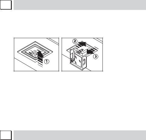
1. FILTRI METALLICI
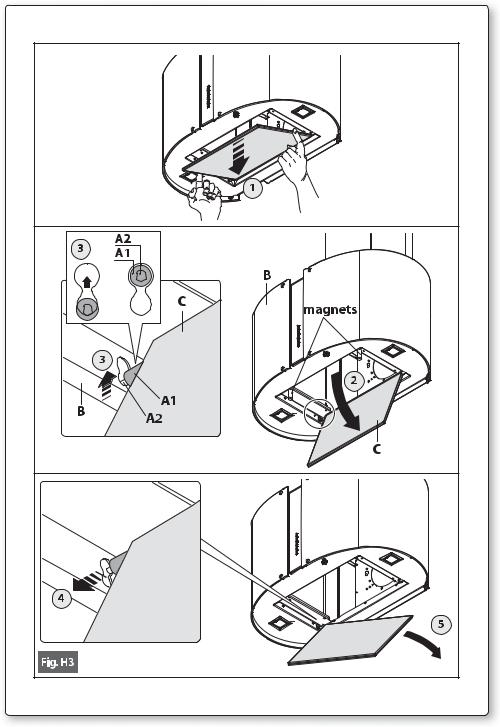
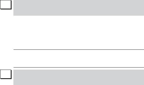
-Aprire il pannello (vedi fig. H3). Per rimuovere il filtro metallico antigrasso agire sulla maniglia A.
Italiano
9
A
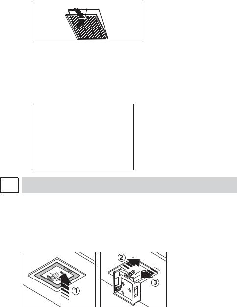
2. FILTRI AL CARBONE ATTIVO
Per la sostituzione dei filtri al carbone attivo si proceda come segue: togliere i filtri metallici come indicato sopra. A questo punto si accede facilmente ai due filtri che sono agganciati sul lato dx e sx del convogliatore.
Per il montaggio/sostituzione vedi figura.
Per ordinare i nuovi filtri carbone rivolgersi al distributore/rivenditore.
SOLO PER ITALIA: Scaricare l’apposito modulo ordine filtro sul sito: www.falmec.com (accedere sul menù a tendina assistenza).
I |
ILLUMINAZIONE MONTAGGIO E SOSTITUZIONE
1. FARETTO
Per sostituire la lampada del “Square halogen light”:
a)Accertarsi che l’apparecchio sia scollegato dalla rete elettrica.
b)Aprire completamente il pannello fino ad un angolo di 90° (vedi figura) premendo su PUSH
c)Sostituire la lampada con una analoga (alogena max 20 W, 12 Volt attacco G4).
d)Richiudere i pannello. Se il pannello non si richiude correttamente ripetere l’operazione al punto b.
2. ILLUMINAZIONE DEI VETRI
Per sostituire la lampada ad incandescenza:
1)accertarsi che la cappa sia scollegata dalla rete elettrica;
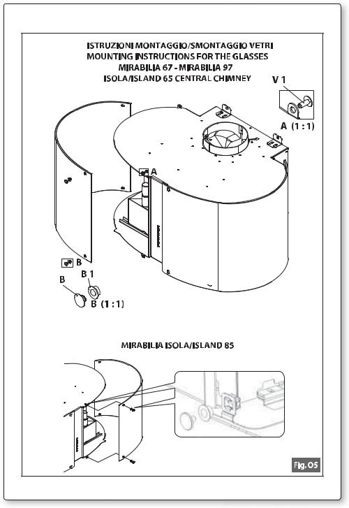
2)rimuovere i vetri decorativi (vedi sez. O);
3)sostituire la lampadina con una dello stesso modello di quella originale (max. 25W);
4)rimontare i vetri (vedi fig. O5).
10
3. ILLUMINAZIONE MIRABILIA LED
La cappa è dotata di illuminazione (luce sul piano di lavoro e luce decorativa sui vetri) a led ad alta efficienza, basso consumo e durata molto elevata in condizioni di normale utilizzo. La sostituzione del faretto led deve essere fatta solo da tecnici qualificati utilizzando solo ricambi originali.
AVVERTENZA: Non rimuovere i vetri se i led di illuminazione dei vetri sono accesi.
L |
MANUTENZIONE E PULIZIA |
Una costante manutenzione garantisce un buon funzionamento ed un buon rendimento nel tempo. Particolari attenzioni vanno rivolte ai filtri metallici antigrasso ed ai filtri al carbone attivo, infatti la pulizia frequente dei filtri e dei loro supporti garantisce che sulla cappa non si accumulino grassi che sono pericolosi per la facilità di incendio.
1. FILTRI ANTIGRASSO METALLICI
Hanno la funzione di trattenere le particelle grasse in sospensione, pertanto si consiglia di lavarli ogni mese in acqua calda e detersivo evitando di piegarli. Attendere che siano ben asciutti prima di rimontarli.
Per lo smontaggio e montaggio vedi istruzioni al punto H1. Si raccomanda costante frequenza nell’operazione.
2. FILTRI AL CARBONE ATTIVO
Hanno la funzione di trattenere gli odori presenti nel flusso d’aria che li attraversa. L’aria depurata per successivi passaggi attraverso i filtri viene rimessa nell’ambiente cucina. l filtri al carbone attivo non possono essere lavati e vanno sostituiti mediamente ogni 3-4 mesi (dipende poi dall’uso). Per la sostituzione dei filtri al carbone attivo seguire le istruzioni come al punto H2.
3. PULIZIA ESTERNA
Si raccomanda di pulire le superfici esterne delle cappe almeno ogni 15 giorni per evitare che le sostanze oleose o grasse possano intaccare le superfici in acciaio.
La pulizia della cappa va eseguita usando un panno umido con detersivo liquido neutro o con alcool denaturato.
Nel caso di materiale con trattamento antimpronta (Fasteel) eseguire la pulizia solo con acqua e sapone neutro utilizzando un panno morbido avendo cura di risciacquare e asciugare accuratamente. Non si devono utilizzare prodotti contenenti sostanza abrasive, panni con superfici ruvide o panni comunemente in commercio per la pulizia dell’acciaio. L’utilizzo di sostanze abrasive e panni ruvidi danneggerà irreparabilmente il trattamento superficiale dell’acciaio. Conseguenza diretta del non rispetto di tali avvertenze sarà il deterioramento irreversibile della superficie dell’acciaio.
Tali avvertenze dovranno essere conservate insieme al libretto istruzioni della cappa. Il produttore declina ogni responsabilità qualora non vengano rispettate tali istruzioni.
4.PULIZIA INTERNA
É vietata la pulizia di parti elettriche o parti relative al motore all’interno della cappa, con liquidi o solventi.
Non usare prodotti contenenti abrasivi.
Effettuare tutte queste operazioni scollegando preventivamente l’apparecchio dalla rete elettrica.
M
 GARANZIA
La sua nuova apparecchiatura è coperta da garanzia. Le condizioni di garanzia sono riportate per esteso sull’ultima pagina di copertina di questo libretto.
La casa costruttrice non risponde delle possibili inesattezze, imputabili ad errori di stampa
Italiano
11

o di trascrizione, contenute nel presente libretto. Si riserva di apportare ai propri prodotti quelle modifiche che ritenesse necessarie o utili, anche nell’interesse dell’utenza, senza pregiudicare le caratteristiche essenziali di funzionalità e di sicurezza.
N |
MONTAGGIO CAPPA
O1 - MONTAGGIO MIRABILIA PARETE
Fase 1
-Appoggiare alla parete la barra di sostegno (A-Fig. O1), ad un’altezza dal piano cottura determinata dalla somma delle quote X+300 mm.
-Controllare con una bolla di livello l’allineamento orizzontale e segnare alle estremità della barra n° 2 punti di foratura.
-Forare, inserire n° 2 tasselli ad espansione ø 8mm e fissare la barra con le relative viti.
Fase 2
-Agganciare la cappa alla barra di sostegno (Fig. O2).
-Regolare l’allineamento della cappa tramite le viti delle attaccaglie:
La vite superiore (B) regola la distanza dalla parete, quella inferiore (C) lo scorrimento verticale.
Fase 3
-Per evitare lo sganciamento della cappa dovuto ad una pressione sottostante, fissarla alla parete con le staffette in dotazione (fig. O3).
-Inserire sul raccordo(D) il tubo (E).
Fase 4
Inserire la prolunga (H) nel camino (G) e fissare l’assieme al corpo cappa mediante le viti (V1).
-Fare scorrere la prolunga (H) fino a raggiungere l’altezza desiderata.
-Trovata la posizione ottimale, appoggiare alla parete la staffa (L), controllare con una bolla di livello l’allineamento orizzontale e segnare alle estremità n°2 punti di foratura.
-Forare, inserire n° 2 tasselli ad espansione ø 4mm e fissare la staffa (L) con le relative viti.
-Avvitare con le viti (M) la prolunga (H) alla staffa (L).
-Alimentare elettricamente la cappa rispettando le norme vigenti (sez. D).
O2 - MONTAGGIO MIRABILIA ISOLA 85/ISOLA 65 CENTRAL CHIMNEY
Fase 1
-Individuare l’altezza desiderata per il posizionamento della cappa.
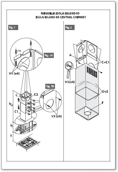
-Far scorrere i tralicci (C) e (C1) fino ad ottenere l’altezza desiderata (H2), successivamente bloccarli con 8 viti (V2) autofilettanti (Fig.1a).
-Fissare il traliccio (C) al soffitto utilizzando 4 fischer da Ø 8 e relative viti (V1) (Fig.1b).
Fase 2
-Infilare la prolunga sul camino e bloccarli tra loro con scotch di carta (Fig. 2).
-Fissare l’assieme camino-prolunga (D+E) al traliccio (C) tramite le 4 viti metriche M4 (V3) inserite nei fori esistenti senza bloccarle definitivamente (Fig. 2).
-Nel caso di versione aspirante: individuare l’altezza ottimale del tubo rigido o flessibile di scarico dei fumi (F) e collegarlo al raccordo motore.
Fase 3
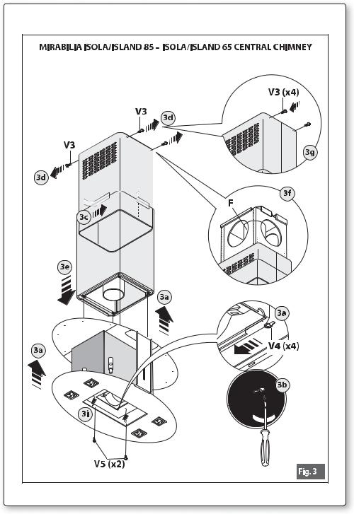
-Alzare la cappa agganciandola alle 4 viti metriche M5 (V4) pre-avvitate al traliccio (C) (centrare i fori Ø11 sull’asola dell’intercamera e traslarla lateralmente) (Fig. 3a).
-Serrare definitivamente le 4 viti M5 (V4) (Fig. 3b).
-Togliere lo scotch di carta (Fig. 3c), togliere le 4 viti metriche M4 (V3) avvitate precedentemente sul traliccio (Fig. 3d) e far scorrere verso il basso l’assieme camino-prolunga (Fig. 3e).
12

- Eseguire il collegamento del tubo al raccordo del foro di scarico del soffitto (nel caso di versione aspirante) (Fig. 3f).
- Eseguire il collegamento elettrico solo dopo aver disinserito l’alimentazione elettrica.
- Fissare la prolunga al traliccio (C) tramite le 4 viti metriche M4 (V3), senza bloccarle definitivamente (Fig. 3g).
- Bloccare definitivamente la prolunga sul traliccio (C) serrando le 4 viti metriche M4 (V3). |
Italiano |
|
- Bloccare il camino tramite 2 viti autofilettanti (V5) (Fig. 3i). |
||
|
||
- Utilizzare gli elementi supporto prolunga (A) (Fig. 2) solo nel caso non venga usato il traliccio |
|
|
superiore, oppure nel caso di un contro-soffitto. |
|
|
- Eseguire il montaggio dei vetri sulla cappa (fig. O5). |
|
13
GB INSTRUCTIONS BOOKLET
A 
 WARNINGS
This instruction booklet must be kept together with the appliance for future reference. If the appliance is sold or consigned to other parties, check that the booklet is supplied with it, to ensure that the new user has the correct information on the operation of the range hood and is aware of the warnings. These warnings have been provided for the your safety and the safety of others. As a result, please read them carefully before installing and operating the appliance.
This appliance is not intended for use by young children or infirm persons unless they have been adequately supervised by a responsible person to ensure that they can use the appliance safely. Young children should be supervised to ensure they do not play with the appliance.
The appliance must be installed by qualified personnel, in accordance with the standards in force. If the supply cord is damaged, it must be re-placed by the manufacturer, its service agent or similarly qualified persons in order to avoid a hazard. Any modifications that may be required to the electrical system for the installation of the range hood must only be made by qualified electricians.
It is dangerous to modify or attempt to modify the characteristics of this system. In the event of malfunctions or if repairs are required to the appliance, do not attempt to solve the problems directly.
Repairs performed by unqualified persons may cause damage. For all repair and other work on the appliance, contact an authorised service/spare parts centre.
Always check that all the electrical parts (lights, exhaust device), are off when the appliance is not being used. Read the entire instruction booklet before performing any operations on the range hood.
The range hood must only be used for the exhaust of cooking fumes in home kitchens. The manufacturer disclaims all liability for any other use of the appliance.
The maximum weight of any object placed above the hood, or hung to it (if possible) must not exceed 1,5 kilos. After installing the stainless steel hood, clean it in order to remove any residue of the protective glue, and stains of grease or oil. The manufacturer recommends its cleaning cloth available for purchase. The manufacturer accepts no liability in case of damage caused by the use of different detergent types.
SAFETY WARNINGS
The electrical system features an earth connection in compliance with international safety standards; furthermore, it is compliant with the European standard for electromagnetic compatibility.
Do not connect the appliance to flues (from boilers, fireplaces, etc.). Make sure the mains voltage corresponds to the values on the rating plate located inside the range hood.
Never cook on “open” flames under the range hood.
Check deep-fryers during use: superheated oil may be flammable.
-Ensure there is adequate ventilation of the room when the rangehood is used at the same time as appliances burning gas or other fuels.
-Do not flambe under the rangehood
-The exhaust air must not be discharged into a flue which is used for exhausting fumes from appliances burning gas or other fuels.
14
-Ensure that all regulations concerning the discharge of exhaust air have been fulfilled before you use the appliance.
Before performing any cleaning or maintenance operations, disconnect the appliance by unplugging it or using the main switch. The manufacturer disclaims all liability for any damage that may be directly or indirectly caused to people, things and animals due to the failure to follow all the instructions provided in this booklet and above all the warnings relating to the installation, operation and maintenance of the appliance.
-there is a fire risk if cleaning is not carried out in accordance with the instructions. CAUTION: Accessible parts may become hot when used with cooking appliances.
-Max. length screw for fixing the chimney is 10 mm (provided by the manufacturer).
WARNING: Failure to install the screws or fixing device in accordance with these instructions may result in electrical hazards.
Warning only for Australia: hood width less than 90 cm: use max. 4 hobs
B 
 TECHNICAL SPECIFICATIONS
The technical data pertaining to the electric appliance The technical specifications of the appliance are shown on the rating plates located inside the range hood.
C 
 INSTALLATION
(Section reserved for qualified installers of the range hood)
The distance between the hob and the lowest part of the rangehood is normally at least 65 cm (see figure C1). This distance is measuresd in the lowest part of the rangehood not operating at safety voltage. Based on this detail provided by European Standards, the distance may be reduced in some models as specified in the general catalogue. If the instructions for installation for the gas hob specify a greater distance, this has to be taken into account.
In the outside exhaust version, the diameter of the fume discharge duct must be no smaller than the range hood connection.
In the horizontal sections, the duct must slope slightly (around 10%) upwards, so as to better convey the air outside of the room.
Avoid using angled pipes, make sure that the pipes are at least of the minimum length. Comply with the current regulations on air discharge into the atmosphere.
If a boiler, stove, fireplace, etc. that uses gas or other fuels is being used at the same time, make sure the room where the fumes are extracted is well ventilated, in compliance with the current regulations.
Mounting instruction: see section “O” of the booklet.
D 
 ELECTRICAL CONNECTIONS
(Section reserved for qualified installers)
WARNING!
Before doing any work inside the range hood, disconnect the appliance from the mains power supply.
Check that the wires inside the range hood are not disconnected or cut; if this is the case, contact your nearest service centre. The electrical connections must be performed by qualified personnel.
The connections must be performed in compliance with the legal standards in force. Check that the relief valve and the electrical system are able to support the load of the appliance (see the technical specifications in point B).
Some types of appliance are supplied with a cable without plug; in this case, “standardised”
English
15

E |
plugs must be used, keeping in mind that:
-the yellow-green wire must be used for the earth,
-the blue wire must be used for the neutral,
-the brown wire must be used for the phase; the cable must not come into contact with hot parts (over 70°C).
-fit a plug that is suitable for the load to the power cable, and connect it to a suitable power outlet.
For appliances that come supplied with cable and plug please ensure they are plugged into a circuit suitable for this appliance.
Please refer to a qualifed person. (See technical specifications in point B).
The manufacturer declines all liability if the safety standards are not observed.
RANGE HOOD WITH OUTSIDE
DISCHARGE (exhaust)
F |
In this version, the fumes and steam from the kitchen are conveyed outside through an exhaust duct.
The exhaust conveyor that protrudes from the upper part of the range hood must be connected to a duct that carries the fumes and steam outside. In this version, the charcoal filters, if fitted, should be removed; to do this, see the instructions in point F. There must be adequate ventilation of the room when the range hood is used at the same time as appliances burning gas or other fuels, according to the standard.
Deviation for Germany:
When the range hood and appliances supplied with energy other than electricity are simultaneously in operation, the negative pressure in the room must not exceed 4 Pa (4x10 E-5 bar).
RECIRCULATING RANGE
HOOD (with filter)
G |
In this version, the air passes through charcoal filters for purification, and is then recirculated back into the kitchen.
Check that the charcoal filters are fitted to the motor, and if not, install them as described in the instructions in point H.
If the hood is of filtering type, remove the non-return valve fitted at the motor’s outlet.
For maximum efficiency, the third speed should be used when there are strong odours or a lot of steam, the second speed in normal conditions, and the first speed for keeping the air clean with minimum energy consumption. The range hood should be switched on when starting to cook, and left on until the odours disappear.
OPERATION
ELECTRONIC CONTROL PANEL
Light pushbutton 

-ON: light on (the pushbutton is lit);
-OFF: light off;
Dimmer with keyboard integrated functions: with motor off and prolonged pressing of keyboard light key (2 seconds), access is gained to the amend atmosphere light intensity (incandescent or LED lamp). By acting on the + and – keys, light intensity is adjusted. With motor started, the prolonged pressing of the key, switches the atmosphere light on or off.
16

H |
Pushbutton -
Press to reduce motor speed
Speed 1, 2 and 3 are indicated by the number of LEDs that light up (excluding the light and the timer LEDs).
Pushbutton +
Press to increase motor speed
Speed 1, 2 and 3 are indicated by the number of LEDs that light up (excluding the light and the timer LEDs). (In the 4-speed version the pushbutton + blinks. The fourth speed remains on for a set duration of time. After 15 minutes the motor returns to the third speed).
Mode pushbutton
Function: it turns hood motor on and off.
The function “desired speed” enables to start the motor at the speed that was selected before the hood was last turned off.
Timer and ‘filter clogged’ alarm pushbutton
-This function allows the automatic turning off of the hood after running for 15 minutes at the speed previously set (the pushbutton shows a flickering light).
-After about 30 hours of running the pushbutton indicates the need for washing the metal filters (the pushbutton shows a solid red light). To disable the alarm press the pushbutton for a few seconds until the red light turns off. Then turn the hood off and on again to check
that the alarm has disappeared.
FILTERS REMOVING AND REPLACING’S INSTRUCTIONS
1. METAL FILTERS
Open the panel (see fig. H3). Use handle A to remove the metal grease filter.
A
English
2. CHARCOAL FILTERS
To replace the charcoal filters, proceed as follows: remove the metal filters as described above. The two filters located at the ends of the motor can now be easily accessed.
To install the new filters see picture.
To order new charcoal filters contact the distributor/retailer.
VALID ONLY FOR ITALY: download the appropriate order form from: www.falmec.com (access the assistance drop-down menu).
17
I |
LIGHTING ASSEMBLY AND REPLACEMENT
1. SPOTLIGHT
How to replace a square halogen light:
a)Check that the equipment is disconnected from the power supply.
b)Open the panel completely till 90° (see figure) pressing the PUSH button
c)Replace the lamp with a similar one (halogen, max 20 W, 12 Volt, G4 connection).
d)Close the panel. If the panel does not close correctly repeat the operation at point b.
2. GLASS LIGHTING
To replace the incandescent lamp:
1)ensure the hood is disconnected from the electric mains;
2)remove the decorative glass (see sec. O);
3)replace the lamp with one of the same model (max. 25W);
4)re-mount the glass (see fig. O5).
3. MIRABILIA LED LIGHTING
The hood is equipped with high efficiency, low power consumption LED lighting (light on the work top and decorative light on the glass panes), with high durability under normal use conditions. The LED spotlight must only be replaced by qualified technicians using original spare parts.
WARNING: Do not remove the glass if the glass LED lighting is on.
L |
MAINTENANCE AND CLEANING
Constant maintenance ensures the correct operation and efficiency of the appliance over time. Special attention should be paid to the metal grease-trapping filters and the charcoal filters. Frequent cleaning of the filters and their supports will ensure that fats and grease do not accumulate on the range hood, with the consequent risk of fire.
1. METAL GREASE-TRAPPING FILTERS
These trap the fat and grease particles suspended in the air, and therefore should be washed every month in hot water and detergent, without bending them. Wait until they are completely dry before repositioning them. To remove and replace these filters, see the instructions in point H1. This operation should be performed at regular intervals.
2. CHARCOAL FILTERS
These trap the odours present in the stream of air that passes through them. The air is purified by passing a number of times through the filters and being recirculated into the kitchen. The charcoal filters cannot be cleaned, and should be replaced on average every 3-4 months (according to use). To replace the charcoal filters, see the instructions in point H2.
3. CLEANING THE OUTSIDE OF THE APPLIANCE
It is advised to clean the external hood surfaces at least every 15 days in order to avoid that oily or greasy substances affect the steel surfaces.
18
The ouside of the range hhod should be cleaned using a damp cloth and neutral liquid detergent or denatured alcohol.
In case of fingerprint-less finish (fasteel) clean only with water and neutral soap using clean with a soft cloth, rinse and wipe dry thoroughly. Do not use products that contain abrasive substances, rough cloths or cloths specifically designed for cleaning steel. Using abrasive substances or rough cloths will inevitably damage the finish of steel. The steel surface will be irrevocably damaged if the instructions above are not complied with.
Keep these instructions together with the instructions for use of your hood.
The manufacturer accepts no liability for any damage caused by non-compliance with the instructions above.
4. CLEANING THE INSIDE OF THE APPLIANCE
The electrical parts or parts of the motor assembly inside the range hood must not be cleaned using liquids or solvents.
Do not use abrasive products. All the above operations must be performed after having disconnected the appliance from the mains power supply.
M
 WARRANTY
The new equipment is covered by warranty.
The warranty conditions are provided by the distributor.
The manufacturer is not liable for any inaccuracies in this booklet resulting from printing or transcription errors. The manufacturer reserves the right to modify its products as it considers necessary or in the interests of the user, without compromising their essential safety and operating characteristics.
N 
 HOOD INSTALLATION
O1 - INSTRUCTIONS FOR WALL-MOUNTED MIRABILIA HOODS Phase 1
-Place the support bar next to the wall (A-Fig. O1), at a height above the cooktop which corresponds to X+300 mm.
-With a spirit level check that the bar is horizontal. Mark a point at each end of the bar.
-Drill the holes, fit 2 ø8mm expansion joints and screw in the bar.
Phase 2
-Fit the hood to the support bar (Fig. O2).
-Adjust hood alignment with the relevant screws: The top screw (B) adjusts the distance from the wall. The bottom screw (C) adjusts the vertical sliding movement.
Phase 3
-To prevent the hood from detaching if pressure is exerted from beneath, secure it to the wall with the brackets supplied (fig. O3).
-Fit pipe/hose (E) into (D).
Phase 4
Place extension (H) in the chimney (G) and fasten this assembly to the body of the hood using screws (V1).
-Slide the extension (H) until it is positioned at the desired height.
-Once you have found the best position, lean the bracket (L) on the wall, verify the horizontal alignment with a spirit level and mark 2 drilling points at the ends.
-Drill the holes, insert 2 expansion bolts of 4mm ø and fasten the bracket (L) with the relative screws.
-Tighten the extension (H) to the bracket (L) using screws (M).
English
19
- Power the hood in accordance with regulations in force (sec. D).
O2 - INSTRUCTIONS FOR MIRABILIA ISLAND 85/ISLAND 65 CENTRAL CHIMNEY
Phase 1
-Identify the desired height for the positioning of the hood.
-Slide the lattice-works (C) and (C1) to the desired height (H2), then block them with the 8 selfthreading screws (V2) (Fig.1a).
-Fasten the lattice-work (C) to the ceiling using the four Ø 8 expansion plugs and relative screws(V1) (Fig.1b).
Phase 2
-Insert the extension on the flue and fasten them to each other with masking tape (Fig. 2).
-Fasten the flue-extension assembly (D+E) to the lattice-work (C) with the 4 M4 metric screws (V3) inserted in the existing holes without tightening them completely (Fig. 2).
-For suction version: identify the optimal height for the rigid or flexible exhaust pipe (F) and connect it to the motor connection.
Phase 3
-Raise the hood, hooking it onto the 4 M5 metric screws (V4) pre-tightened to the lattice-work
(C) (center the Ø11 holes on the slot of the inner liner and move it laterally)(Fig. 3a).
-Completely tighten the 4 M5 screws (V4) (Fig. 3b).
-Remove the masking tape (Fig. 3c), remove the four M4 metric screws (V3) previously tightened onto the lattice-work (Fig. 3d) and slide the flue-extension assembly downwards. (Fig. 3e).
-Connect the pipe to the connection of the ceiling discharge hole. (Fig. 3f).
-Make electrical connections only after having removed electrical power supply.
-Fasten the extension to the lattice-work (C) by means of the 4 M4 metric screws (V3), without tightening them completely(Fig. 3g).
-Block the extension completely to the lattice-work (C) by screwing down the 4 M4 metric screws (V3).
-Block the flue with the 2 self-threading screws (V5) (Fig. 3i).
-Use the extension support elements(A) (Fig. 2) only if the upper lattice-work is not used, or in the case of a false ceiling.
-Fit the glass panels (fig. O5).
20
D BEDIENUNGSANLEITUNG
A 
 HINWEISE
Diese Bedienungsanleitung muss unbedingt zusammen mit dem Gerät aufbewahrt werden, um in Zukunft nachgeschlagen werden zu können.
Sollte das Gerät verkauft bzw. einer anderen Person übergeben werden, muss die Bedienungsanleitung unbedingt mitgeliefert werden, damit der neue Benutzer mit dem Betrieb der Dunstabzugshaube und den diesbezüglichen Hinweisen vertraut werden kann.
Diese Hinweise sind für Ihre Sicherheit und die anderer Personen abgefasst worden. Daher sollten Sie die Bedienungsanleitung vor der Installation und Verwendung des Gerätes aufmerksam durchlesen.
Das Gerät darf nicht von Kindern bzw. Behinderten benutzt werden, es sei denn diese werden von verantwortungsvollen Personen, die dafür Sorge tragen, dass das Gerät sicher verwendet wird, überwacht.
Kinder müssen von einer von verantwortungsvollen Person überwacht werden, damit sie nicht mit dem Gerät spielen.
Die Installation hat den geltenden Vorschriften gemäß von kompetenten, qualifizierten Installateuren durchgeführt zu werden.
Beschädigte Speisekabel sind vom Hersteller bzw. von dessen Kundenservice bzw. von einer Person mit ähnlicher Qualifikation auszuwechseln, um Gefahren vorzubeugen.
Eventuelle erforderliche Änderungen, die für die Installation der Dunstabzugshaube an der elektrischen Anlage durchgeführt werden müssen, dürfen ausschließlich von kompetenten Personen vorgenommen werden.
Es ist gefährlich, die Eigenschaften dieser Anlage abzuändern bzw. versuchen abzuändern. Bei Reparaturen bzw. Betriebsstörungen des Gerätes nicht versuchen, das Problem alleine zu lösen.
Die Reparaturen, die von nicht kompetenten Personen durchgeführt werden, können Schäden verursachen.
Sich für eventuelle Eingriffe an einen zugelassenen Kundenservice, der über die geeigneten Ersatzteile verfügt, wenden.
Wenn das Gerät nicht benutzt wird, müssen alle elektrischen Teile (Beleuchtung, Absaugvorrichtung) ausgeschaltet sein. Vor Durchführung von Arbeitsvorgängen an der Dunstabzugshaube die Bedienungsanleitung lesen.
Die Dunstabzugshaube darf ausschließlich zum Absaugen des Dampfes, der beim Kochen in einer Haushaltsküche entsteht, verwendet werden.
Bei anderen Einsätzen wird der Hersteller von jeder Haftung befreit.
Das Gesamtgewicht von Gegenständen, die eventuell auf die Dunstabzugshaube positioniert bzw. an diese gehängt werden (falls vorgesehen), darf höchstens 1,5 Kg betragen.
Nach der Installation von Edelstahlhauben muss man diese reinigen, um Schutzkleberreste und eventuelle Fettund Ölflecken zu entfernen.
Der Hersteller empfiehlt für doesen Arbeitsvorgang die Verwendung der mitgelieferten Reinigungstücher.
Die Verwendung anderer Reinigungsmittel befreit den Hersteller von jeder Haftung für eventuelle auf deren Benutzung zurückzuführende Schäden.
SICHERHEITSBESTIMMUNGEN
Die elektrische Anlage ist mit einer Erdung ausgestattet, die den internationalen Sicherheitsvorschriften entspricht; sie erfüllt außerdem die europäischen Entstörungsvorschriften.
21
Deutsch
 Loading...