


VALENTINA INSERT
FIVAL28B5SS-1
FIVAL34B5SS-1
EN |
INSTRUCTION BOOKLET |
FR |
MODE D'EMPLOI |
ES |
MANUAL DE INSTRUCCIONES |
IT |
LIBRETTO ISTRUZIONI |
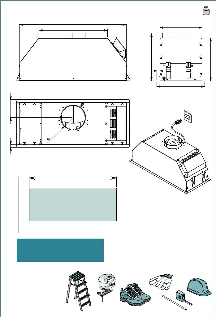
VALENTINA 28" Cod.: FIVAL28B5SS-1
25 3/4" - 654 MM |
16 7/16" - 417 MM |
4 5/16" |
109 MM |
MM |
15/16" |
MM |
5 |
||
150 |
|
|
11/16" - 17 |
|
|
|
|
CUTOUT DIMENSIONS
26 1/4" - 666 MM
10 5/16" - 262 MM
EN - MEASUREMENTS FOR INSTALLATION
FR - MESURES DU TROU POUR ENCASTREMENT
ES - MEDIDAS DEL ORIFICIO PARA EMPOTRADO
IT - MISURE FORO PER INCASSO
ENtool required
FRoutil requis
ESherramienta requerida
IT - Attrezzi necessari
12 kg
26,4 lb
|
10 1/8" - 257MM |
|
- 292MM |
MM |
|
11 1/2" |
3/8" - 293 |
|
11/16" |
10 |
|
17 MM |
||
|
||
|
11 9/16" - 293 MM |
120VAC 60Hz 280W
ENcable length 5,0ft (1,5m)
FRlongueur de câble 5,0ft (1,5m)
ESlongueur de câble 5,0ft (1,5m)
ITlunghezza cavo 5,0ft (1,5m)
2
11/16" - 17 MM
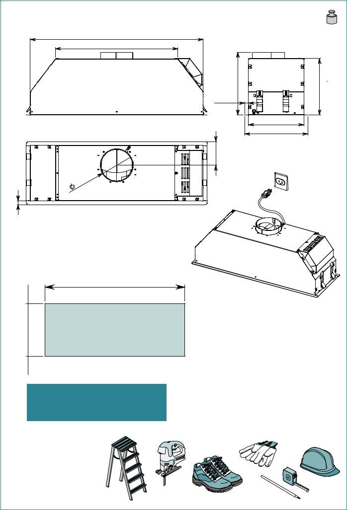
VALENTINA 34" Cod.: FIVAL34B5SS-1 |
14 kg |
|
31 lb |
31 11/16" - 804MM |
|
22 7/16" - 569 MM |
|
- 292MM |
MM |
11 1/2" |
- 293 |
17 MM |
103/8" |
11/16" |
|
|
4 5/16" |
109 MM |
15/16" |
|
|
5 |
MM |
|
150 |
|
|
|
|
|
10 1/8" - 255 MM |
11 9/16" - 293 MM |
120VAC 60Hz 280W
CUTOUT DIMENSIONS
31 15/16" - 811 MM
10 5/16" - 262 MM
EN - MEASUREMENTS FOR INSTALLATION
FR - MESURES DU TROU POUR ENCASTREMENT ES - MEDIDAS DEL ORIFICIO PARA EMPOTRADO IT - MISURE FORO PER INCASSO
ENtool required
FRoutil requis
ESherramienta requerida
IT - Attrezzi necessari
ENcable length 5,0ft (1,5m)
FRlongueur de câble 5,0ft (1,5m) ESlongueur de câble 5,0ft (1,5m) ITlunghezza cavo 5,0ft (1,5m)
3
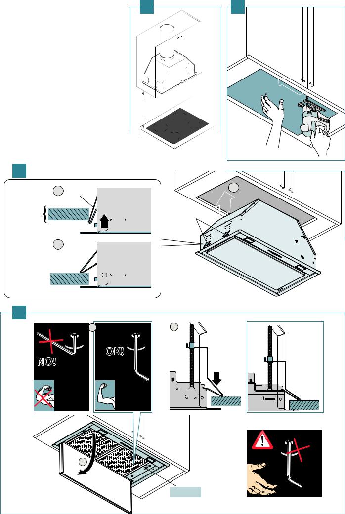
EN |
- Installation measurements (1), cabinet cutout (2), |
|
1 |
2 |
|
|
|
|
|||
|
hood installation (3), mounting to the cabinet (4) |
|
|
|
|
FR |
- Mesures pour installation (1), perçage meuble (2), |
|
|
|
|
|
mise en place de la hotte (3), |
|
|
|
|
|
ixation au meuble (4) |
|
|
|
|
ES |
- Medidas instalación (1), |
|
|
|
|
|
oriicio armario de pared (2), |
|
|
|
|
|
introducción campana (3), |
|
|
|
|
|
ijación en el armario de pared (4) |
|
|
|
|
IT |
- Misure installazione (1), foratura pensile (2), |
|
|
|
|
|
inserimento cappa (3), issaggio al pensile (4) |
|
|
|
|
|
|
|
24 |
13⁄32” |
|
|
|
|
|
|
|
|
|
|
620 |
|
|
|
|
|
MM |
|
|
|
3 |
|
|
|
|
|
2 |
|
|
|
1 |
|
MO |
|
|
|
|
|
|
|
|
|
|
|
MIN 15⁄32” |
|
|
|
|
|
MAX 25⁄32” |
|
|
|
|
|
MIN 12 MM |
|
|
|
M O |
|
|
|
|
|
|
|
MAX 20 MM |
|
|
|
|
3 |
|
|
|
4 |
|
|
|
V1 (x4) |
2 |
V1 (x4) |
3 |
|
|
||
|
|
OK! |
|
NO! |
|
|
|
|
|
|
V1 (x4) |
|
|
|
Only for |
1 |
|
|
maint. |
|
|
|
|
|
|
|
MAGNET |
|
|
|
4 |
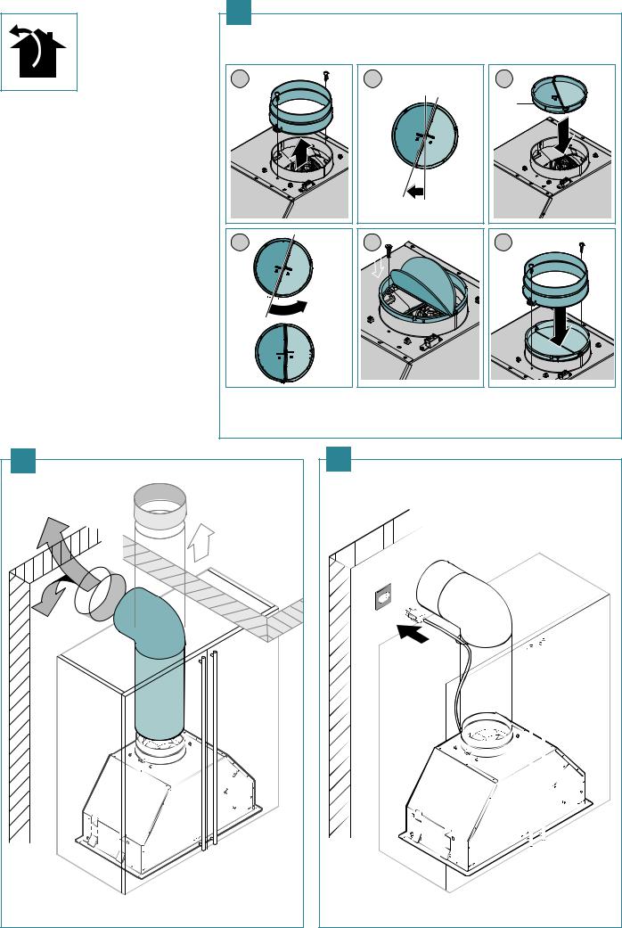
EN |
- Installation of check valve (5), suction pipe (6) |
|
and electrical connection (7) |
FR |
- Installation clapet de non retour (5), tuyau |
|
d'aspiration (6) et branchement électrique (7) |
ES |
- Instalación de la válvula de no-retorno (5), |
|
tubo de aspiración (6) y conexión eléctrica (7) |
IT |
- Installazione valvola di non ritorno (5), tubo |
|
di aspirazione (6) e collegamento elettrico (7) |
6
5 |
|
|
1 |
2 |
3 |
ERM |
|
M |
|
|
|
4 |
5 |
6 |
|
|
ERM |
|
7 |
|
5
8
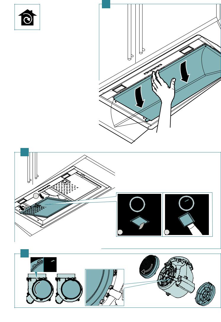
EN - Assembling standard active carbon ilter: remove panel (8), remove metal ilters (9), assemble active carbon ilters (10).
FR - Montage iltre au charbon actif standard : déposer le panneau (8), retirer les iltres métalliques (9), monter les iltres au charbon actif (20).
ES - Montaje del iltro de carbón activo de serie: quite el panel (8), quite los iltros metálicos (9), monte los iltros de carbón activo (10).
IT - Montaggio iltro carbone attivo di serie: rimuovere pannello (8), rimuovere iltri metallici (9), montare iltri carbone attivo (10).
9 |
|
3 |
|
1 |
2 |
10 |
|
6

EN |
- How to uninstall: remove panel (11), remove metal |
11 |
|
|
|
|
|
||
|
ilters (12), unscrew ixing screws (13), release built-in |
|
|
|
|
unit (14). |
|
|
|
FR |
- Procédure de désinstallation : déposer le panneau |
|
|
|
|
(11), enlever les iltres métalliques (12), dévisser les vis |
|
|
|
|
de ixation (13), extraire le groupe à encastrement (14). |
|
|
|
ES |
- Procedimiento de desmontaje: quite el panel (11), quite |
|
|
|
|
los iltros metálicos (12), destornille los tornillos de |
|
|
|
|
ijación (13), desbloquee el grupo de empotrado (14). |
|
1 |
|
IT |
- Procedura di disinstallazione: rimuovere pannello (11), |
|
|
|
|
rimuovere iltri metallici (12), svitare viti di tenuta(13), |
|
|
|
|
sbloccare gruppo incasso (14). |
|
|
|
|
|
|
|
5 |
|
|
2 |
3 |
4 |
12 |
|
14 |
|
|
|
|
1 |
|
|
EN |
- Safety bracket (Pull!) |
1 |
2 |
FR |
- Patte de sécurité (Tirer !) |
|
|
ES |
- Abrazadera de seguridad (¡Tire!) |
|
|
IT |
- Sta a di sicurezza (Tirare!) |
|
3 |
|
|
13 |
|
|
|
1 |
|
2 |
|
|
|
|
|
|
V1( X 4 |
) |
|
|
|
|
2 |
7

SAFETY INSTRUCTIONS
AND WARNINGS
Installation operations are to be carried out by skilled and qualiied installers in accordance with the instructions in this booklet and in compliance with the regulations in force.
DO NOT use the hood if the power supply cable or other components are damaged: disconnect the hood from the electrical power supply and contact the Dealer or an authorised Servicing Dealer for repairs.
Do not modify the electrical, mechanical or functional structure of the equipment.
Do not personally try to carry out repairs or replacements. Interventions carried out by incompetent and unauthorised persons can cause serious damage to the unit or physical and personal harm, not covered by the Manufacturer's warranty.
WARNINGS FOR THE INSTALLER
TECHNICAL SAFETY
Before installing the hood, check the integrity and function of each part. Should anomalies be noted, do not proceed with installation and contact the Dealer.
Do NOT install the hood if an aesthetic (or cosmetic) defect has been detected. Put it back into its original package and contact the dealer.
No claim can be made for aesthetic (or cosmetic) defects once it has been installed.
During installation, always use personal protective equipment (e.g.: Safety shoes) and adopt prudent and proper conduct.
The installation kit (screws and plugs) supplied with the hood is only to be used on masonry walls: in case of installation on walls of a di erent material, assess other installation options keeping in mind the type of wall surface and the weight of the hood (indicated on spec sheets at the beginning of this manual).
Keep in mind that installations with di erent types of fastening systems from those supplied, or which are not compliant, can cause electrical and mechanical seal danger.
Do not install the hood outdoors and do not expose it to atmospheric elements (rain, wind, etc.).
ELECTRICAL SAFETY
The electrical system to which the hood is to be connected must be in accordance with local standards and supplied with earthed connection in compliance with safety regulations in the country of use. It must also comply with local standards regarding radio antistatic properties.
Before installing the hood, check that the electrical mains power supply corresponds with what is reported on the identification plate located inside the hood.
The socket used to connect the installed equipment to the electrical power supply must be within reach: otherwise, install a mains switch to disconnect the hood when required.
Any changes to the electrical system must be carried out by a qualified electrician.
The maximum length of the flue fastening screws (supplied by the manufacturer) must be 13 mm. Use of non-compliant screws with these instructions can lead to danger of an electrical nature.
Do not try to solve the problem yourself in the event of equipment malfunction, but contact the Dealer or an authorised Servicing Department for repairs.
When installing the hood, disconnect the equipment by removing the plug or switching of the main switch.
FUMES DISCHARGE SAFETY
Do no connect the equipment to discharge pipes of fumes produced from combustion (for example boilers, ireplaces, etc.).
Before installing the hood, ensure that all standards in force regarding discharge of air out of the room have been complied with.
USER WARNINGS
These warnings have been drawn up for your personal safety and those of others. You are therefore kindly asked to read the booklet carefully in its entirety before using the or cleaning the equipment.
The Manufacturer declines all responsibility for any damage caused directly, or indirectly, to persons, things and pets as a consequence of failing to comply with the safety warnings indicated in this booklet.
It is imperative that this instructions booklet is kept together with the equipment for any future consultation.
If the equipment is sold or transferred to another person, make sure that the booklet is also supplied so that the new user can be made aware of the hood's operation and relative warnings.
After the stainless steel hood has been installed, it will need to be cleaned to remove any residues remaining from the protective coating as well as any grease and oil stains which, if not removed, can cause irreversible damage to the hood surface. To properly clean the unit, the manufacturer recommends using the supplied moist wipes, which are also available sold separately.
Insist on original spare parts.
INTENDED USE
The equipment is solely intended to be used to extract fumes generated from cooking food in non-professional domestic kitchens: any other use is improper. Improper use can cause damage to persons, things, pets and exempts the Manufacturer from any liability.
The equipment can be used by children over the age of 8 and by persons with reduced physical, sensory and mental abilities, or with no experience or knowledge, as long as they do so under supervision or after having received relative instructions regarding safe use of the equipment and understanding of the dangers connected to it.
Children are not to play with the equipment. Cleaning and maintenance by the user must not be carried out by children without supervision.
CLEANING WARNINGS
Before cleaning or carrying out maintenance operations, disconnect the equipment by removing the plug or switching of the main switch.
Do not use the hood with wet hands or bare feet.
Always check that all electrical parts (lights, extractor fan) are o when the equipment is not being used.
The maximum overall weight of any objects placed or hung (if applicable) on the hood must not exceed 3lb 5oz (1.5 Kg).
Always supervise the cooking process during the use of deep-fryers: Overheated oil can catch fire.
Do not leave open, unattended flames under the hood. Do not prepare food over an open flame under the hood.
Never use the hood without the metal anti-grease filters: in this case, grease and dirt will deposit in the equipment and compromise its operation.
Accessible parts of the hood can be hot when used at the same time as the cooking appliances.
Do not carry out any cleaning operations when parts of the hood are still hot.
There can be a risk of fire if cleaning is not carried out according to the instructions and products indicated in this booklet.
Disconnect the main switch when the equipment is not used for long periods of time.
If other appliances that use gas or other fuels are being used at the same time (boiler, stove, ireplaces, etc.), make sure the room where the fumes are discharged is well-ventilated, in compliance with the local regulations.
INSTALLATION
Intended only for qualiied personnel
Before installing the hood, carefully read the section 'SAFETY INSTRUCTIONS AND WARNINGS'.
TECHNICAL FEATURES
The technical specifications are exhibited on the labels located inside the hood.
POSITIONING
The minimum distance between the highest part of the cooking equipment and the lowest part of the hood is indicated in the installation instructions.
Should the instructions for the gas cooker specify a greater distance, this must be taken into consideration.
Do not install the hood outdoors and do not expose it to outdoor environment (rain, wind, etc.).
8
 Loading...