

Fairchild Semiconductor MMBD1205, MMBD1203, MMBD1201 Datasheet
MMBD1201 / 1203 / 1204 / 1205
3
3
24
2
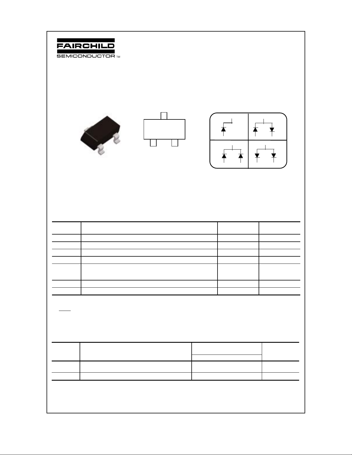
SOT-23
1
MMBD1201 24 MMBD1204A 27
MMBD1203 26 MMBD1205A 28
High Conductance Ultra Fast Diode
12
MARKING
Discrete POWER & Signal
Technologies
CONNECTION DIAGRAMS
1201
1204
3
2 NC
1
3
21
3
1203
21
3
1205
21
MMBD1201 / 1203 / 1204 / 1205
Sourced from Process 1P.
Absolute Maximum Ratings* TA = 25°C unless otherwise noted
Symbol Parameter Value Units
W
IV
I
O
I
F
i
f
i
f(surge)
T
stg
T
J
Working Inverse Voltage 50 V
Average Rectified Current 200 mA
DC Forward Current 600 mA
Recurren t Peak Forward Current 700 mA
Peak Forward Surge Current
Pulse width = 1.0 second
Pulse width = 1.0 microsecond
Storage Temperature Range -55 to +150
Operating Junction Temperature 150
1.0
2.0
A
A
°
°
C
C
*These ratings are limiting values above which the serviceability of any semiconductor device may be impaired.
NOTES:
1) These ratings are based on a maximum junction temperature of 150 degrees C.
2) These are steady state limits. The factory should be consulted on applications involving pulsed or low duty cycle operations.
Thermal Characteristics TA = 25°C unless otherwise noted
Symbol Characteristic Max Units
MMBD1201/1203/1204/1205*
P
D
R
θ
JA
*Device mounted on glass epoxy PCB 1.6" X 1.6" X 0.06"; mounting pad for the collector lead min. 0.93 in2
Total Dev ice Dissipation
Derate above 25°C
350
2.8
Thermal Resistan ce, Junction to Ambient 357
mW
mW/°C
C/W
°
ã 1997 Fairchild Semiconductor Corporation
µ
High Conductance Ultra Fast Diode
(continued)
Electrical Characteristics TA = 25°C unless otherwise noted
Symbol Parameter Test Conditions Min Max Units
B
V
I
R
V
F
C
T
T
RR
Breakdown Voltage
I
= 100 µA
R
Reverse Current VR = 20 V
V
= 50 V
R
V
= 50 V, TA = 150°C
R
Forward Voltage IF = 1.0 mA
I
= 10 mA
F
= 100 mA
I
F
I
= 200 mA
F
I
= 300 mA
F
100 V
25
50
5.0
550
660
820
0.87
600
740
920
1.0
1.1
nA
nA
mV
mV
mV
Diode Capacitance VR = 0, f = 1.0 MHz 2.0 pF
Reverse Recovery Time IRR = 1.0 mA, IF = IR = 10 mA,
R
= 100
Ω
L
4.0 nS
A
V
V
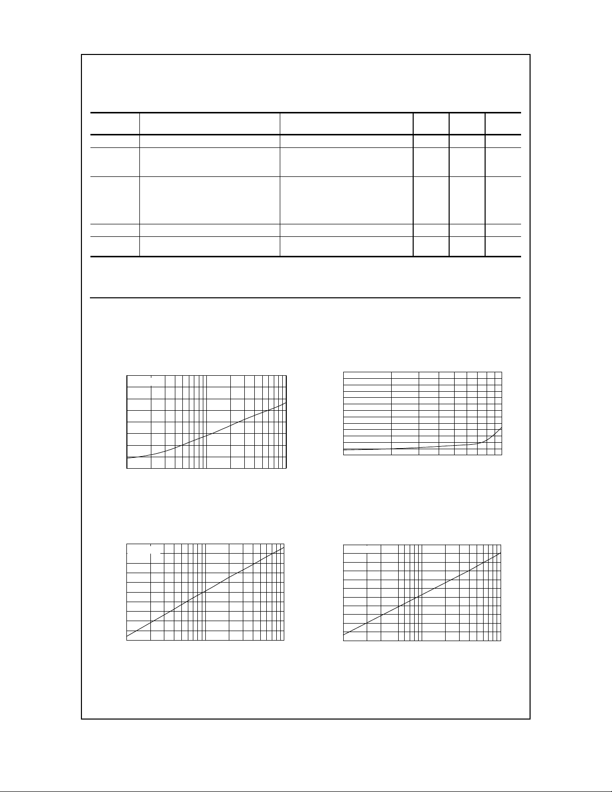
Typical Characteristics
MMBD1201 / 1203 / 1204 / 1205
REVERSE VOLTAGE vs REVERSE CURRENT
BV - 1.0 to 100 uA
150
Ta= 25°C
140
130
120
R
R
V
V - REVERSE VOLTAGE (V)
110
1 2 3 5 10 20 30 50 100
I - REVERSE CURRENT (uA)
R
FORWARD VOLTAGE vs FORWARD CURRENT
VF - 1.0 to 100 uA
485
Ta= 25°C
450
400
350
300
250
F
F
V
V - FORWARD VOLTAGE (mV)
225
1 2 3 5 10 20 30 50 100
F
I - FORWARD CURRENT (uA)
REVERSE CURRE NT vs REVERSE VOLTAGE
IR - 10 to 100 V
Ta= 25°C
300
250
200
150
100
50
R
0
I - REVERSE CURRENT (nA)
10 20 30 50 70 100
GENERAL RULE: The Reverse Current of a diode will approximately
V - REVERSE VOLTAGE (V)
R
double for every ten (10) Degree C increase in Temperature
FORWARD VOLTAGE vs FORWARD CURRENT
725
Ta= 25°C
700
650
600
550
500
F
F
V
V - FORWARD VOLTAGE (mV)
450
0.1 0.2 0.3 0.5 1 2 3 5 10
VF - 0.1 to 10 mA
F
I - FORWARD CURRENT (mA)
 Loading...