


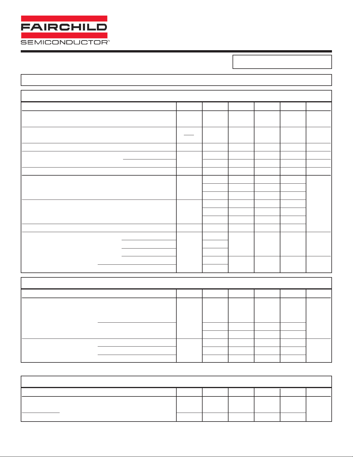
ABSOLUTE MAXIMUM RATINGS
Parameter Symbol Value Units
TOTAL DEVICE
T
STG
-55 to +150 °C
Storage Temperature
Operating Temperature T
OPR
-55 to +100 °C
Lead Solder Temperature T
SOL
260 for 10 sec °C
Total Device Power Dissipation @ TA= 25°C
P
D
260 mW
Derate above 25°C 3.5 mW/°C
Input-Output Isolation Voltage V
ISO
5300 Vac(rms)
EMITTER
I
F
60 mA
Forward Input Current
Reverse Input Voltage V
R
6.0 V
Forward Current - Peak (1µs pulse, 300pps) IF(pk) 3.0 A
LED Power Dissipation @ TA= 25°C
P
D
100 mW
Derate above 25°C 1.8 mW/°C
DETECTOR
Collector-Emitter Voltage
H11G1 V
CEO
100 V
H11G2 80
H11G3 55
Detector Power Dissipation @ TA= 25°C
P
D
200 mW
Derate above 25°C 2.67 mW/°C
FEATURES
• High BV
CEO
- Minimum 100 V for H11G1
- Minimum 80 V for H11G2
- Minimum 55 V for H11G3
• High sensitivity to low input current
Minimum 500 percent CTR at I
F
= 1 mA
• Low leakage current at elevated temperature
(maximum 100 µA at 80°C)
• Underwriters Laboratory (UL) recognized File# E90700
DESCRIPTION
The H11GX series are photodarlington-type optically coupled optocouplers. These devices have a
gallium arsenide infrared emitting diode coupled with a silicon darlington connected phototransistor
which has an integral base-emitter resistor to optimize elevated temperature characteristics.
7/21/00 200045A
HIGH VOLTAGE
PHOTODARLINGTON OPTOCOUPLERS
H11G1
H11G2
H11G3
APPLICATIONS
• CMOS logic interface
• Telephone ring detector
• Low input TTL interface
• Power supply isolation
• Replace pulse transformer
NOTE
All dimensions are in inches (millimeters)
ANODE
CATHODE
1
2
BASE
6
COLLECTOR
5
N/C
3
4
EMITTER
ELECTRICAL CHARACTERISTICS
(TA= 25°CUnless otherwise specified.)
7/21/00 200045A
Characteristic Test Conditions Symbol Device Min Typ** Max Unit
EMITTER
(I
F
= 10 mA) V
F
ALL 1.3 1.50 V
Forward Voltage
Forward Voltage Temp. V
F
ALL -1.8 mV/°C
Coefficient T
A
Reverse Breakdown Voltage (IR= 10 µA) BV
R
ALL 3.0 25 V
Junction Capacitance
(V
F
= 0 V, f = 1 MHz)
C
J
ALL 50 pF
(VF= 1 V, f = 1 MHz) ALL 65 pF
Reverse Leakage Current (VR= 3.0 V) I
R
ALL 0.001 10 µA
DETECTOR H11G1 100
Breakdown Voltage (IC= 1.0 mA, IF= 0) BV
CEO
H11G2 80
Collector to Emitter H11G3 55
H11G1 100 V
Collector to Base (IC= 100 µA)
BV
CBO
H11G2 80
H11G3 55
Emitter to Base BV
EBO
ALL 7 10
(VCE= 80 V, IF= 0) H11G1
Leakage Current
(V
CE
= 60 V, IF= 0) H11G2 100 nA
Collector to Emitter
(V
CE
= 30 V, IF= 0) I
CEO
H11G3
(VCE= 80 V, IF= 0, TA= 80°C) H11G1
100 µA
(VCE= 60 V, IF= 0, TA= 80°C) H11G2
INDIVIDUAL COMPONENT CHARACTERISTICS
DC Characteristic Test Conditions Symbol Device Min Typ** Max Unit
EMITTER
Current Transfer Ratio
(I
F
= 10 mA, VCE= 1 V) H11G1/2 100 (1000)
Collector to Emitter
CTR mA (%)
(IF= 1 mA, VCE= 5 V)
H11G1/2 5 (500)
H11G3 2 (200)
(IF= 16 mA, IC= 50 mA) H11G1/2 0.85 1.0
Saturation Voltage (IF= 1 mA, IC= 1 mA) V
CE (SAT)
H11G1/2 0.75 1.0 V
(IF= 20 mA, IC= 50 mA) H11G3 0.85 1.2
TRANSFER CHARACTERISTICS
Characteristic Test Conditions Symbol Device Min Typ** Max Unit
SWITCHING TIMES
(R
L
= 100 1, IF= 10 mA) t
on
ALL 5
Turn-on Time µs
Turn-off Time (VCE= 5 V) Pulse Width 6300 µs, f 630 Hz) t
off
ALL 100
TRANSFER CHARACTERISTICS
HIGH VOLTAGE
PHOTODARLINGTON OPTOCOUPLERS
H11G1, H11G2, H11G3
** All typical values at TA= 25°C
 Loading...