

Page 1
FTB-5230S/-OCA
Optical Spectrum and Channel Analyzers
for FTB-200 v2
User Guide
Page 2

Copyright © 2013 EXFO Inc. All rights reserved. No part of this publication
may be reproduced, stored in a retrieval system or transmitted in any form,
be it electronically, mechanically, or by any other means such as
photocopying, recording or otherwise, without the prior written permission
of EXFO Inc. (EXFO).
Information provided by EXFO is believed to be accurate and reliable.
However, no responsibility is assumed by EXFO for its use nor for any
infringements of patents or other rights of third parties that may result from
its use. No license is granted by implication or otherwise under any patent
rights of EXFO.
EXFO’s Commerce And Government Entities (CAGE) code under the North
Atlantic Treaty Organization (NATO) is 0L8C3.
The information contained in this publication is subject to change without
notice.
Trademarks
EXFO’s trademarks have been identified as such. However, the presence
or absence of such identification does not affect the legal status of any
trademark.
Units of Measurement
Units of measurement in this publication conform to SI standards and
practices.
Patents
Feature(s) of this product is/are protected by one or more of US patents
6,636,306; 8,358,930; 8,364,034 and equivalent patents pending and granted
in other countries; patent appl. US 2013/0163987 A1; and US patents
6,612,750 and 8,373,852.
Version number: 10.0.9
ii FTB-5230S/-OCA
Page 3

Contents
Certification Information ........................................................................................................v
1 Introducing the FTB-5230S/-OCA Optical Spectrum
and Channel Analyzers ................................................................................. 1
Models ....................................................................................................................................2
Typical Applications ................................................................................................................2
Optional Software Packages ...................................................................................................3
Post-Processing Application ....................................................................................................3
Conventions ............................................................................................................................4
2 Safety Information ....................................................................................... 5
3 Getting Started with Your OSA/OCA ............................................................ 7
Inserting and Removing Test Modules ....................................................................................7
Starting Module Applications ...............................................................................................13
4 Preparing Your OSA/OCA for a Test ........................................................... 17
Cleaning and Connecting Optical Fibers ...............................................................................17
Installing the EXFO Universal Interface (EUI) .........................................................................19
Selecting a Test Mode ...........................................................................................................20
Nulling Electrical Offsets .......................................................................................................22
Performing User Calibration ..................................................................................................24
Using the Autonaming Feature .............................................................................................36
5 Setting Up the Instrument in WDM Mode ................................................ 43
Defining Preferences .............................................................................................................45
Setting Up WDM Analysis Parameters ...................................................................................61
Setting Up Acquisition Parameters ........................................................................................88
6 Setting Up the Instrument in Drift Mode ................................................. 91
Defining Preferences .............................................................................................................93
Setting Up Drift Analysis Parameters ..................................................................................107
Setting Up Acquisition Parameters ......................................................................................132
Building a Custom Drift Measurement ................................................................................139
7 Setting Up Your OCA ................................................................................ 149
8 Starting a Measurement .......................................................................... 153
OSA/OCA iii
Page 4

9 Managing Files and Test Configurations .................................................155
Using the Discover Feature .................................................................................................155
Managing Measurement Files .............................................................................................158
Opening Other Test Mode Files in WDM Mode ...................................................................162
Managing Favorites ............................................................................................................163
Importing a Configuration from the Current Trace .............................................................173
Using a Restore Point ..........................................................................................................173
10 Managing Results .....................................................................................175
Managing WDM Test Results ..............................................................................................176
Managing Drift Test Results ................................................................................................185
Managing OCA Test Results ................................................................................................196
Adjusting the Display Size ...................................................................................................201
Viewing WDM Graph in Full-Screen Mode ..........................................................................203
Using Zoom Controls ..........................................................................................................204
Managing Markers .............................................................................................................206
Managing Trace Information ..............................................................................................210
Generating Reports .............................................................................................................214
11 Maintenance ..............................................................................................217
Cleaning EUI Connectors ....................................................................................................217
Recalibrating the Unit .........................................................................................................220
Recycling and Disposal (Applies to European Union Only) ..................................................221
12 Troubleshooting ........................................................................................223
Viewing Online Documentation ..........................................................................................223
Contacting the Technical Support Group ............................................................................224
Transportation ....................................................................................................................226
13 Warranty ....................................................................................................229
General Information ...........................................................................................................229
Liability ...............................................................................................................................230
Exclusions ...........................................................................................................................231
Certification ........................................................................................................................231
Service and Repairs .............................................................................................................232
EXFO Service Centers Worldwide ........................................................................................233
A Technical Specifications ............................................................................235
Index ...............................................................................................................237
iv FTB-5230S/-OCA
Page 5

Certification Information
Certification Information
North America Regulatory Statement
This unit was certified by an agency approved in both Canada and the
United States of America. It has been evaluated according to applicable
North American approved standards for product safety for use in Canada
and the United States.
Electronic test and measurement equipment is exempt from FCC part 15,
subpart B compliance in the United States of America and from ICES-003
compliance in Canada. However, EXFO Inc. makes reasonable efforts to
ensure compliance to the applicable standards.
The limits set by these standards are designed to provide reasonable
protection against harmful interference when the equipment is operated in
a commercial environment. This equipment generates, uses, and can
radiate radio frequency energy and, if not installed and used in accordance
with the user guide, may cause harmful interference to radio
communications. Operation of this equipment in a residential area is likely
to cause harmful interference in which case the user will be required to
correct the interference at his own expense.
Modifications not expressly approved by the manufacturer could void the
user's authority to operate the equipment.
European Community Declaration of Conformity
An electronic version of the declaration of conformity for your product is
available on our website at www.exfo.com. Refer to the product’s page on
the Web site for details.
OSA/OCA v
Page 6

Page 7
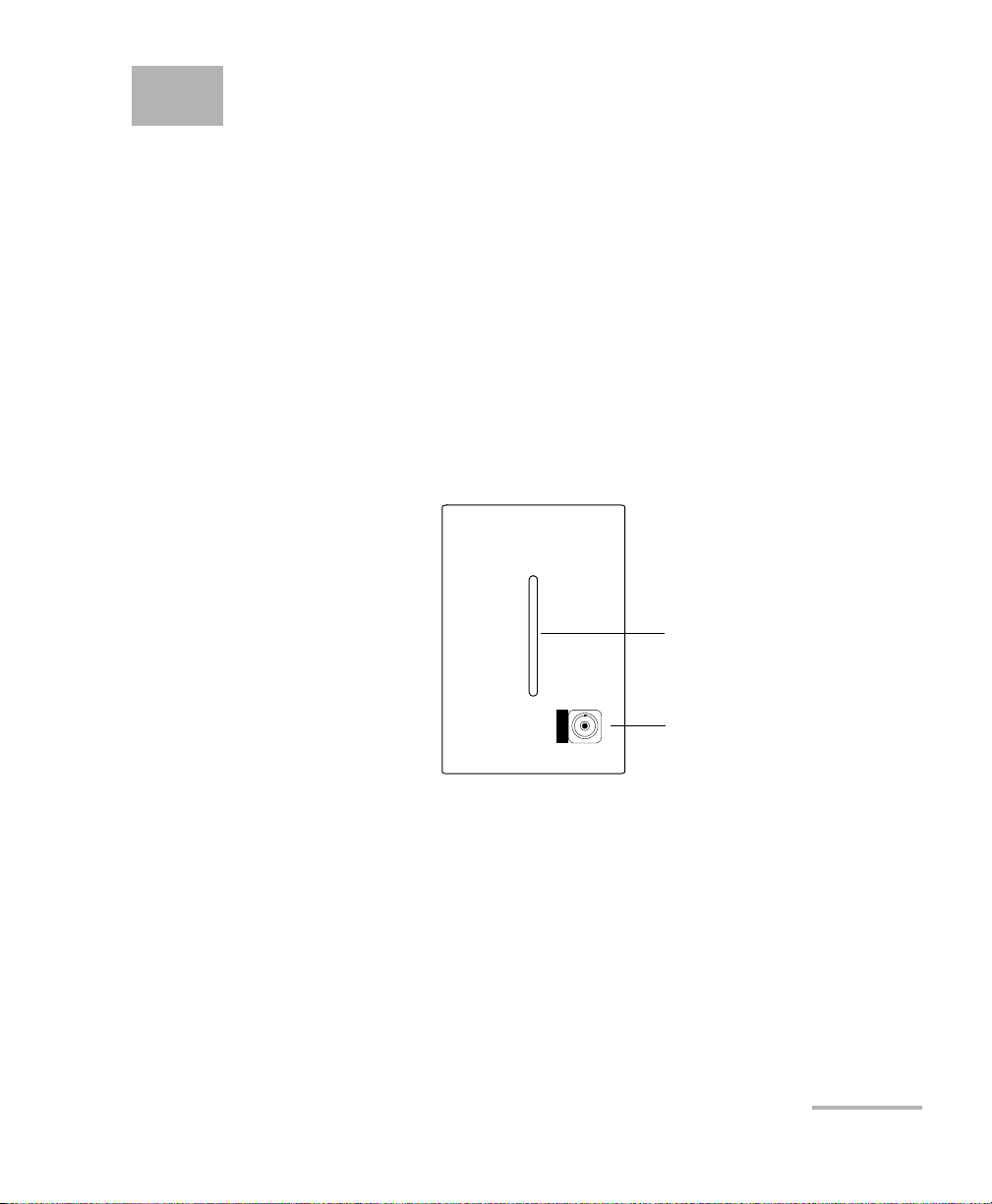
1 Introducing the
Input port
Handle
FTB-5230S/-OCA Optical
Spectrum and Channel
Analyzers
The FTB-5230S Optical Spectrum Analyzer (OSA) is designed to measure
optical power as a function of wavelength or frequency and Optical Signal
to Noise Ratio (OSNR) based on the IEC method (interpolation method).
It offers truly portable spectral characterization for DWDM network
commissioning.
The FTB-5230S-OCA Optical Channel Analyzer (OCA) is designed to
measure optical power as a function of wavelength or frequency.
OSA/OCA 1
Page 8

Introducing the FTB-5230S/-OCA Optical Spectrum and Channel Analyzers
Models
Models
The OSA/OCA comes in different models:
The FTB-5230S is an entry-level optical spectrum analyzer that is ideal
for a variety of field applications, including DWDM and CWDM network
commissioning and troubleshooting. The test modes available for your
module are WDM and Drift.
The FTB-5230S-OCA (Optical Channel Analyzer): This model is
designed to measure optical power as a function of wavelength or
frequency. It offers truly portable spectral characterization for CWDM
and DWDM network commissioning.
Typical Applications
You can use your OSA/OCA for the following tasks:
Characterizing channels in the O- to U-band spectra (OSA only)
Troubleshooting and monitoring key parameters on CWDM or DWDM
signals to check system stability
Characterizing all channel spacings, from 50 GHz DWDM to CWDM
Testing high-speed networks (beyond 40 Gbit/s)
2 FTB-5230S/-OCA
Page 9

Introducing the FTB-5230S/-OCA Optical Spectrum and Channel Analyzers
Optional Software Packages
Optional Software Packages
Optional software options are available for your OCA application.
Note: Software options are not available on the OSA.
Option Name Description
WDM This option enables you to perform full WDM analyses as
well as WDM drift measurements, just as you would with
an FTB-5230S OSA.
Post-Processing Application
A post-processing, or offline version of the application is available for you to
use on a conventional computer. This offline version has most of the
module application, but does not allow you to perform acquisitions.
Note: The post-processing application is not available for the OCA.
OSA/OCA 3
Page 10

Introducing the FTB-5230S/-OCA Optical Spectrum and Channel Analyzers
Conventions
Conventions
Before using the product described in this guide, you should understand
the following conventions:
WARNING
Indicates a potentially hazardous situation which, if not avoided,
could result in death or serious injury. Do not proceed unless you
understand and meet the required conditions.
CAUTION
Indicates a potentially hazardous situation which, if not avoided,
may result in minor or moderate injury. Do not proceed unless you
understand and meet the required conditions.
CAUTION
Indicates a potentially hazardous situation which, if not avoided,
may result in component damage. Do not proceed unless you
understand and meet the required conditions.
IMPORTANT
Refers to information about this product you should not overlook.
4 FTB-5230S/-OCA
Page 11
2 Safety Information
WARNING
Do not install or terminate fibers while a light source is active.
Never look directly into a live fiber and ensure that your eyes are
protected at all times.
WARNING
The use of controls, adjustments and procedures other than those
specified herein may result in exposure to hazardous situations or
impair the protection provided by this unit.
IMPORTANT
When you see the following symbol on your unit , make sure
that you refer to the instructions provided in your user
documentation. Ensure that you understand and meet the required
conditions before using your product.
IMPORTANT
Other safety instructions relevant for your product are located
throughout this documentation, depending on the action to
perform. Make sure to read them carefully when they apply to your
situation.
CAUTION
The following symbol indicates that your unit is equipped with a
laser source: .
OSA/OCA 5
Page 12
Safety Information
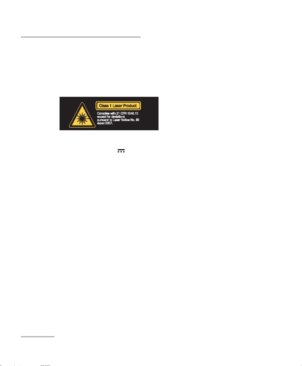
Your instrument is a Class 1 laser product in compliance with standards
IEC 60825-1: 2007 and 21 CFR 1040.10, except for deviations pursuant to
Laser Notice No. 50, dated June 24, 2007. Invisible laser radiation may be
encountered at the output port.
The following label indicates that a product contains a Class 1 source:
The maximum input power for the FTB-5230S/-OCA Optical Spectrum and
Channel Analyzers is 4 W. For more information on equipment
ratings, refer to the user documentation for your platform.
6 FTB-5230S/-OCA
Page 13

3 Getting Started with Your
OSA/OCA
Inserting and Removing Test Modules
CAUTION
Never insert or remove a module while the FTB-200 v2 is turned on.
This will result in immediate and irreparable damage to both the
module and unit.
CAUTION
To avoid damaging your unit, use it only with modules approved by
EXFO.
WARNING
When the laser safety LED is flashing, at least one of your modules
is emitting an optical signal. Please check all modules, as it might
not be the one you are currently using.
OSA/OCA 7
Page 14
Getting Started with Your OSA/OCA
Inserting and Removing Test Modules
To insert a module into the FTB-200 v2:
1. Turn off your unit.
2. Position the unit so that its front panel is facing you.
8 FTB-5230S/-OCA
Page 15
Getting Started with Your OSA/OCA
Inserting and Removing Test Modules
3. Take the module and place it vertically so that the retaining screw hole
is at the left of the connector pins.
CAUTION
Inserting a module upside down could result in permanent damage
to the module, as the connector pins might be bent.
4. Insert the protruding edges of the module into the grooves of the unit’s
module slot.
5. Push the module all the way to the bottom of the slot, until the
retaining screw makes contact with the unit casing.
6. Place the unit so that its bottom panel is facing you.
OSA/OCA 9
Page 16
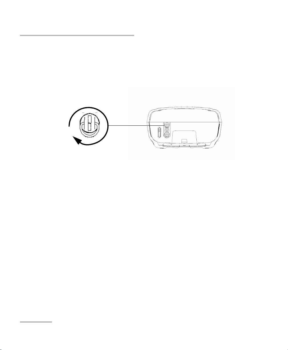
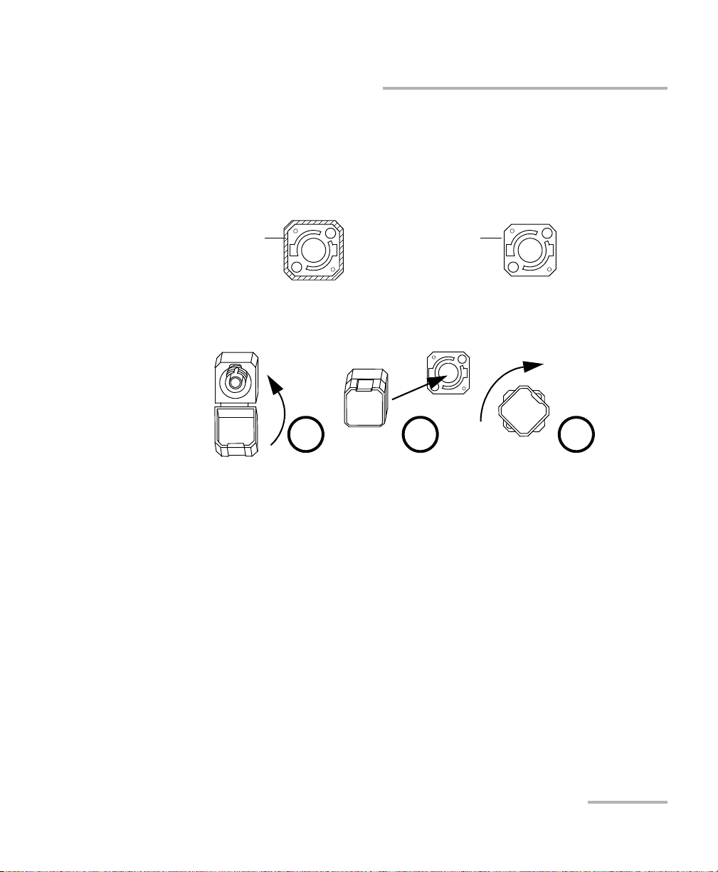
Getting Started with Your OSA/OCA
Turn retaining screws
clockwise
Bottom panel
Inserting and Removing Test Modules
7. While applying slight pressure to the module, lift the mobile part of the
retaining screw and use it to turn the retaining screw clockwise until it
is tightened.
This will secure the module into its “seated” position.
When you turn on the unit, the startup sequence will automatically detect
the module.
10 FTB-5230S/-OCA
Page 17
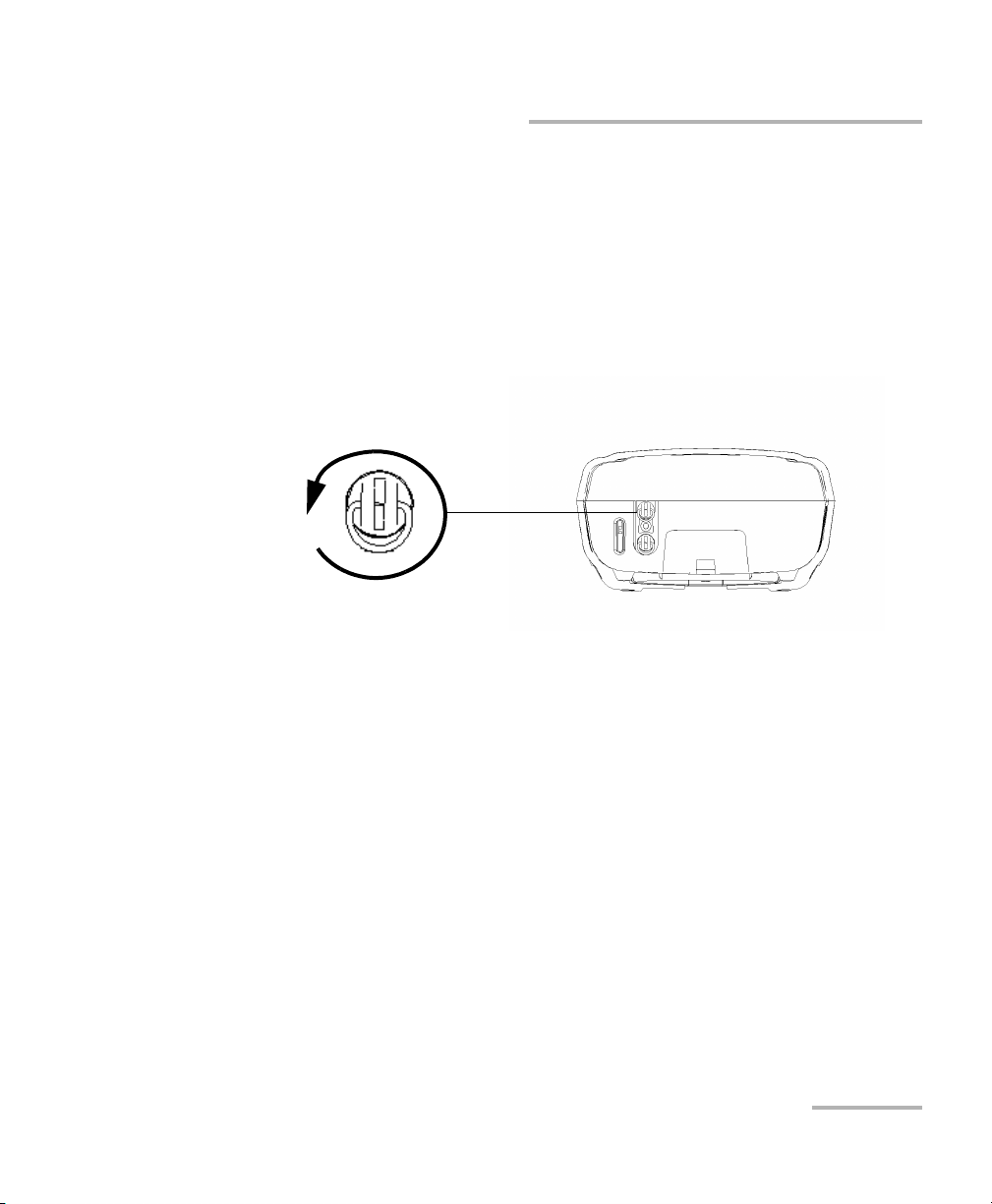
Getting Started with Your OSA/OCA
Turn retaining screws
counterclockwise
Bottom panel
Inserting and Removing Test Modules
To remove a module from the FTB-200 v2:
1. Turn off your unit.
2. Position the unit so that the bottom panel is facing you.
3. Lift the mobile part of the retaining screw and use it to turn the
retaining screw counterclockwise until it stops.
The module will be slowly released from the slot.
4. Place the unit so that the top panel is facing you.
OSA/OCA 11
Page 18
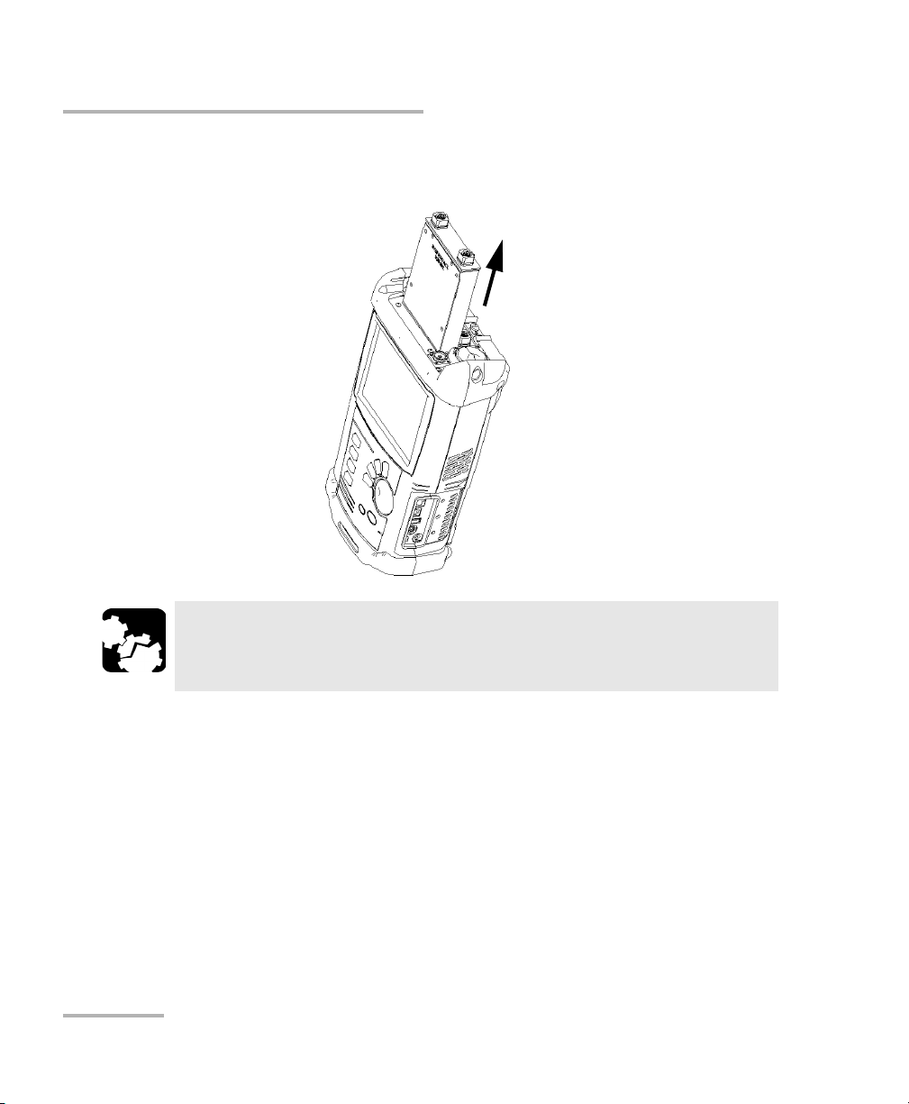
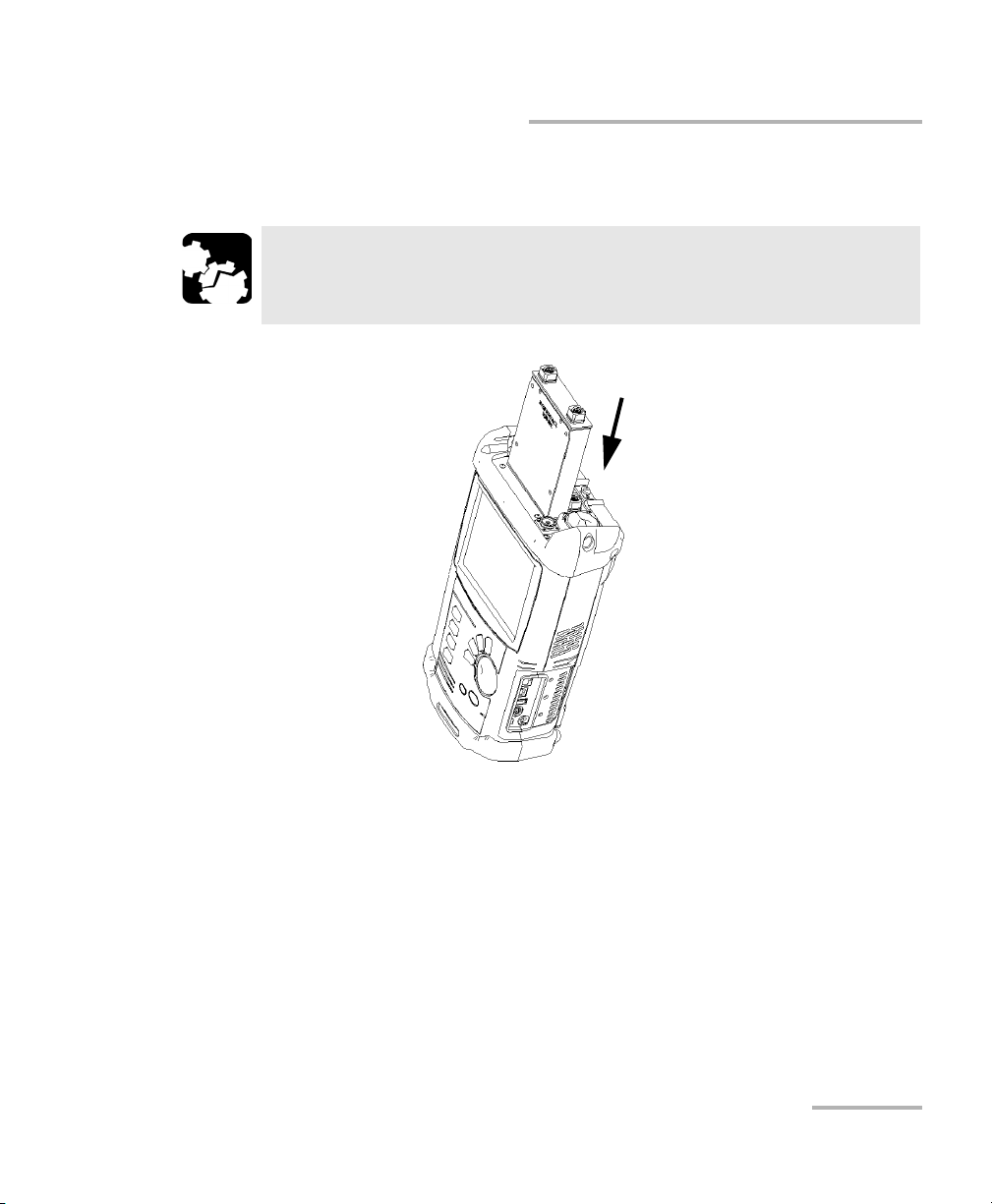
Getting Started with Your OSA/OCA
Inserting and Removing Test Modules
5. Hold the module by its sides or by the handle (NOT by the connector)
and pull it out.
CAUTION
Pulling out a module by a connector could seriously damage both
the module and connector. Always pull out a module by its casing.
6. Cover empty slots with the supplied protective covers.
12 FTB-5230S/-OCA
Page 19
Getting Started with Your OSA/OCA
Starting Module Applications
Starting Module Applications
Your modules can be configured and controlled from their dedicated
applications in Compact ToolBox.
To start a module application:
1. From Compact ToolBox, select the module to use.
It will turn blue to indicate that it is highlighted.
OSA/OCA 13
Page 20
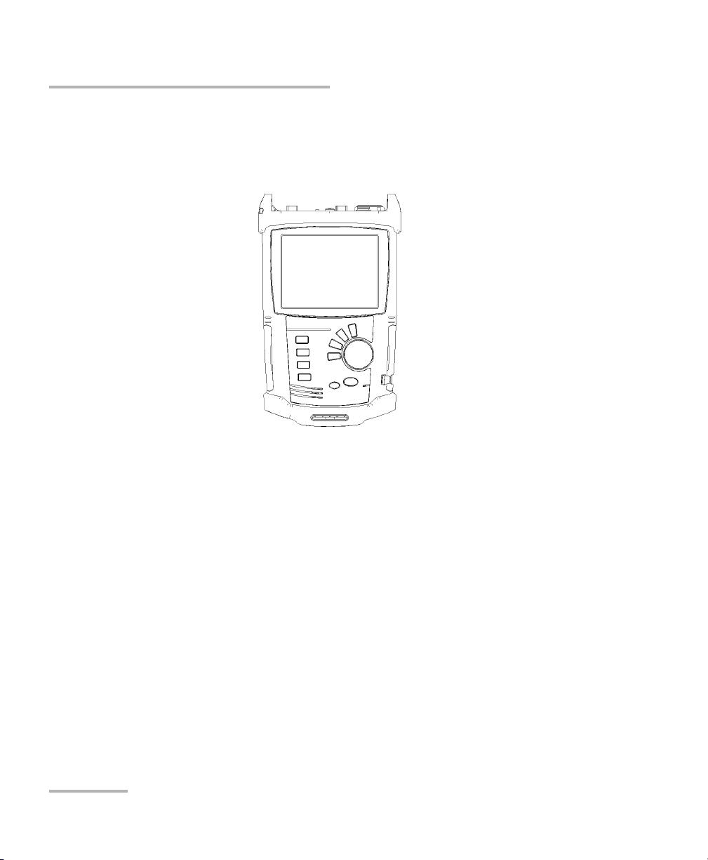
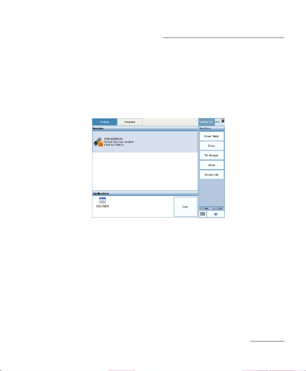
Getting Started with Your OSA/OCA
Display
panes
Result
panes
Function
buttons
FTB-5230S
Starting Module Applications
2. Under Applications, select an application, then press Start.
To start the Power Meter or Probe application:
From Main Menu, press Power Meter or Probe.
The main window (shown below) contains all the commands required to
control the OSA/OCA:
14 FTB-5230S/-OCA
Page 21
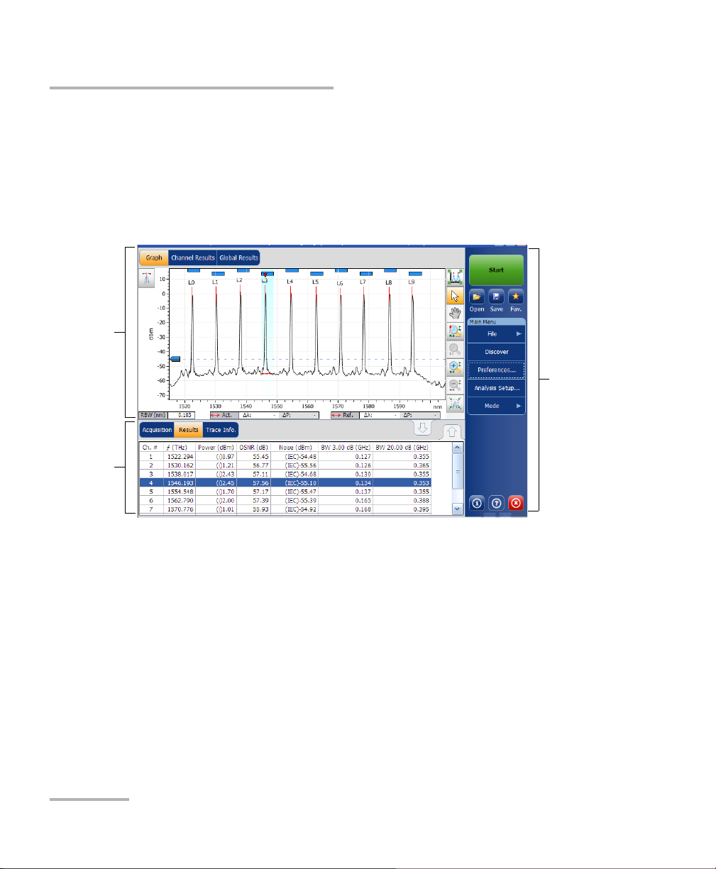
Getting Started with Your OSA/OCA
Graph
Result
panes
Function
buttons
FTB-5230S-OCA
Starting Module Applications
Note: The illustrations in this user guide may differ slightly from those on your unit
depending on the resolution, application and platform type.
OSA/OCA 15
Page 22

Page 23

4 Preparing Your OSA/OCA for a
Test
IMPORTANT
For optimal test results, you should allow a minimum warm up
period of two hours for your OSA/OCA before starting your tests.
Cleaning and Connecting Optical Fibers
IMPORTANT
To ensure maximum power and to avoid erroneous readings:
Always inspect fiber ends and make sure that they are clean as
explained below before inserting them into the port. EXFO is
not responsible for damage or errors caused by bad fiber
cleaning or handling.
Ensure that your patchcord has appropriate connectors. Joining
mismatched connectors will damage the ferrules.
To connect the fiber-optic cable to the port:
1. Inspect the fiber using a fiber inspection microscope. If the fiber is
clean, proceed to connecting it to the port. If the fiber is dirty, clean it as
explained below.
2. Clean the fiber ends as follows:
2a. Gently wipe the fiber end with a lint-free swab dipped in isopropyl
alcohol.
2b. Use compressed air to dry completely.
2c. Visually inspect the fiber end to ensure its cleanliness.
OSA/OCA 17
Page 24

Preparing Your OSA/OCA for a Test
Cleaning and Connecting Optical Fibers
3. Carefully align the connector and port to prevent the fiber end from
touching the outside of the port or rubbing against other surfaces.
If your connector features a key, ensure that it is fully fitted into the
port’s corresponding notch.
4. Push the connector in so that the fiber-optic cable is firmly in place,
thus ensuring adequate contact.
If your connector features a screwsleeve, tighten the connector
enough to firmly maintain the fiber in place. Do not overtighten, as this
will damage the fiber and the port.
Note: If your fiber-optic cable is not properly aligned and/or connected, you will
notice heavy loss and reflection.
EXFO uses good quality connectors in compliance with EIA-455-21A
standards.
To keep connectors clean and in good condition, EXFO strongly
recommends inspecting them with a fiber inspection probe before
connecting them. Failure to do so will result in permanent damage to the
connectors and degradation in measurements.
18 FTB-5230S/-OCA
Page 25
Preparing Your OSA/OCA for a Test
Bare metal
(or blue border)
indicates UPC
option
Green border
indicates APC
option
2 3 4
Installing the EXFO Universal Interface (EUI)
Installing the EXFO Universal Interface (EUI)
The EUI fixed baseplate is available for connectors with angled (APC) or
non-angled (UPC) polishing. A green border around the baseplate
indicates that it is for APC-type connectors.
To install an EUI connector adapter onto the EUI baseplate:
1. Hold the EUI connector adapter so the dust cap opens downwards.
2. Close the dust cap in order to hold the connector adapter more firmly.
3. Insert the connector adapter into the baseplate.
4. While pushing firmly, turn the connector adapter clockwise on the
baseplate to lock it in place.
OSA/OCA 19
Page 26
Preparing Your OSA/OCA for a Test
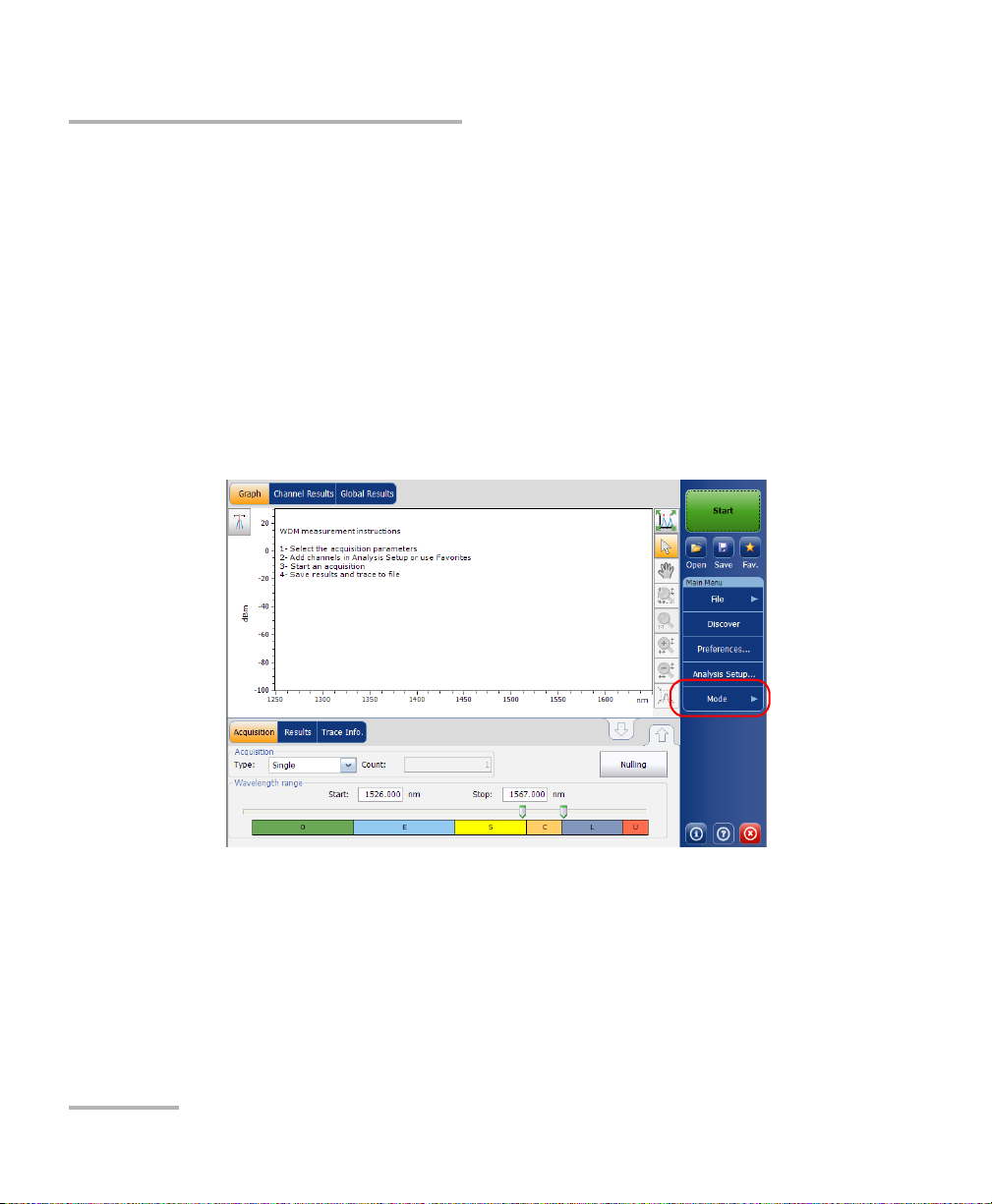
Selecting a Test Mode
Selecting a Test Mode
Your module gives you different ways to test all your DWDM systems:
WDM: Allows you to analyze an optical link. By default, the WDM test
mode is selected.
Drift: Allows you to monitor an optical link for a fixed duration.
Note: You cannot select a test mode in the OCA application.
To select a test mode:
1. From the Main Menu, press Mode.
20 FTB-5230S/-OCA
Page 27
Preparing Your OSA/OCA for a Test
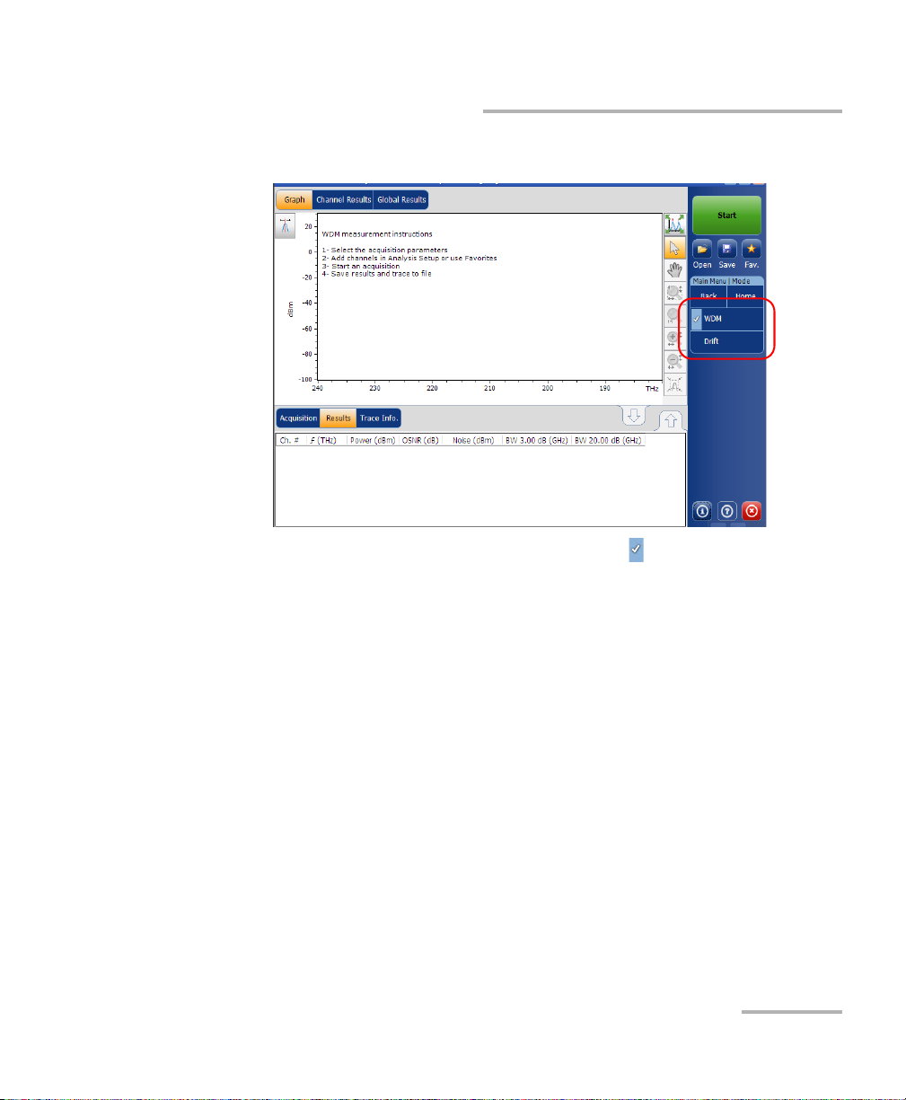
Selecting a Test Mode
2. Select the desired test mode.
Once you select the mode, you will notice a against the selected
mode and all the tabs on the main window and the main menu will
change accordingly.
After selecting the test mode, you must configure it. You will find
specific instructions for your test mode in the corresponding related
chapters.
OSA/OCA 21
Page 28
Preparing Your OSA/OCA for a Test
Nulling Electrical Offsets
Nulling Electrical Offsets
The offset nulling process provides a zero-power reference measurement,
thus eliminating the effects of electronic offsets and dark current due to
detectors.
Temperature and humidity variations affect the performance of electronic
circuits and optical detectors. For this reason, EXFO recommends
performing a nulling of the electrical offsets whenever environmental
conditions change.
Nulling can be performed for all tests modes. In addition, a nulling is
performed automatically each time you start the OSA/OCA application, and
at regular intervals afterwards.
Note: You cannot perform an offset nulling in the offline version of the
application.
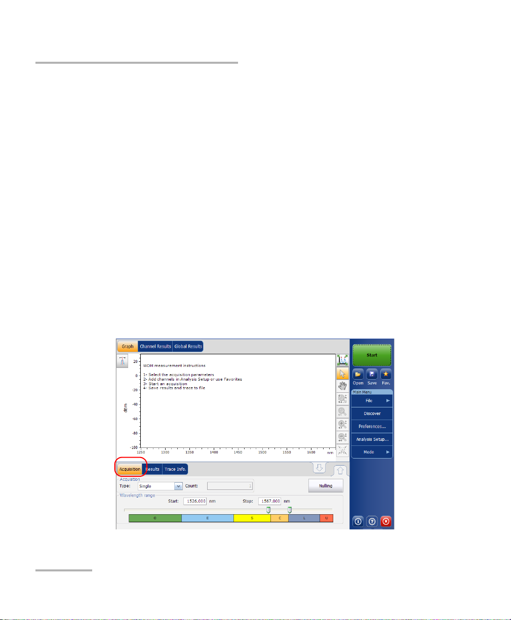
To perform an offset nulling:
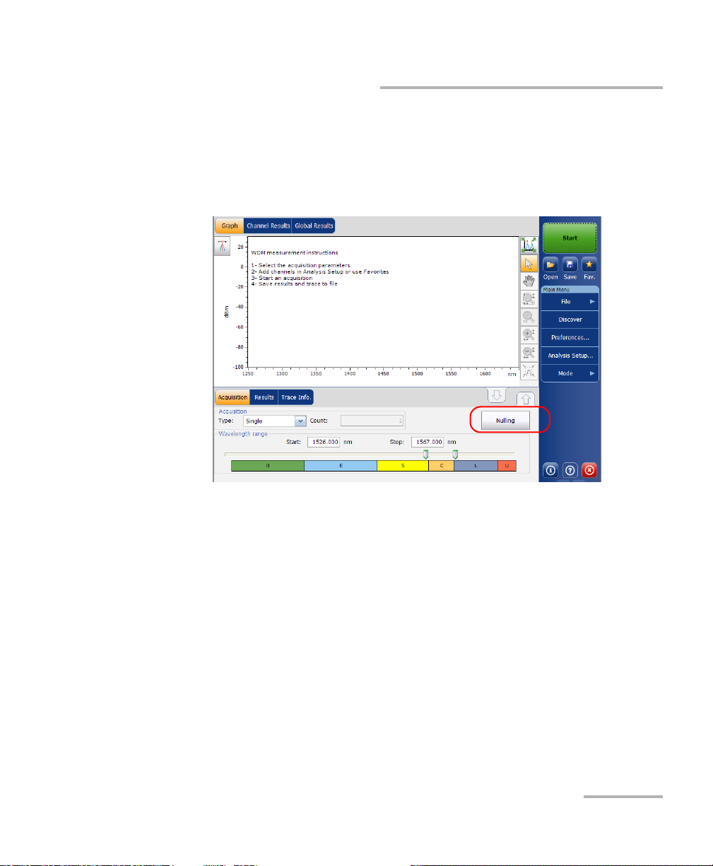
1. From the main window, select the Acquisition tab.
22 FTB-5230S/-OCA
Page 29
Preparing Your OSA/OCA for a Test
Nulling Electrical Offsets
2. Disconnect any incoming signal to obtain an optimal accuracy.
3. Press Nulling.
You are notified that the nulling is in progress in the status bar. Nulling
should be completed in a few seconds.
Note: Several features, such as the Start button and Discover, are not available
during the nulling process.
OSA/OCA 23
Page 30

Preparing Your OSA/OCA for a Test
Performing User Calibration
Performing User Calibration
Calibrating your module can help you achieve better results. It is
particularly important when the measurement accuracy is critical or when
your OSA/OCA has experienced unusual shock or vibrations. To reach the
highest possible accuracy, you can perform a wavelength or power
calibration. Your OSA/OCA allows you to modify and read the user
calibration values, revert to the factory calibration, load and save the
modified user calibration file. The user configuration file (*.txt) contains
the reference and modified wavelength and power values.
You can perform user calibration in any test mode. Select a test mode as
explained in Selecting a Test Mode on page 20, and follow the procedures
mentioned below for performing user calibration.
Note: The procedure is not available for the OCA application.
Note: The procedure for performing user calibration is the same for all test
modes. The procedure is explained with WDM mode only in this document.
IMPORTANT
For optimal results, you should allow a minimum warm up period
of two hours for your OSA/OCA before performing user calibration.
IMPORTANT
You must clear the correction factor list before making new
calibration measurements. If calibration measurements are made
when user correction factors are inside the module, the latter will
affect the measurements and the calibration results become
inapplicable.
Note: If you want to keep the correction factor list for a later use, save it under a
different name in the folder.
24 FTB-5230S/-OCA
Page 31

Preparing Your OSA/OCA for a Test
Performing User Calibration
Note: The user calibration feature is not available in the offline version of the
OSA/OCA application.
To perform a user calibration:
1. Allow your unit to warm up.
2. From the Main Menu, press Analysis Setup.
OSA/OCA 25
Page 32

Preparing Your OSA/OCA for a Test
Performing User Calibration
3. Select the Calibration tab.
Note: You cannot edit the power or wavelength values directly from the
application. The modifications in the user calibration have to be made in a
text file, and then it can be loaded in the application.
26 FTB-5230S/-OCA
Page 33

Preparing Your OSA/OCA for a Test
Performing User Calibration
4. If user correction factors are in the system, press Clear User
Correction Factors from Module, then confirm your choice.
5. Take measurements for your test mode.
OSA/OCA 27
Page 34

Preparing Your OSA/OCA for a Test
Performing User Calibration
6. Note the measurements to a .txt file using the following format:
The first column is the reference wavelengths, in nm.
The second column is the wavelength read by your module, in nm.
The third column is the reference power, in dBm.
The fourth column is the power read by your module, in dBm.
Note: The columns are separated by a semi-colon (;). You can have up to 100
calibration points.
Here is an example of a measurement file:
1310.154; 1310.167; -1.34; -1.55
1490.000; 1490.000; 1.09; 1.15
1551.334; 1551.298; -5.20; -5.45
1625.401; 1625.448; 0.00; 0.00
Note: The decimal separator is a point ( . ). This format is independent of the
regional settings.
7. Save your .txt file in a location of your choice.
28 FTB-5230S/-OCA
Page 35

Preparing Your OSA/OCA for a Test
Performing User Calibration
8. Back in the Calibration tab on your unit, load the file using Load
Fact o rs.
9. Select the modified user calibration file and press Open.
OSA/OCA 29
Page 36

Preparing Your OSA/OCA for a Test
Performing User Calibration
The calibration values will replace the Correction factors list in the
Analysis setup - Calibration window.
30 FTB-5230S/-OCA
Page 37

Preparing Your OSA/OCA for a Test
Performing User Calibration
10. Press Write to Module to apply the modified calibration values to the
module.
OSA/OCA 31
Page 38

Preparing Your OSA/OCA for a Test
Performing User Calibration
11. To verify that the calibration changes are properly applied to the
module, press Load from Module.
Note: The OK and Cancel buttons do not have any impact on the calibration
page or the correction factors inside the module.
32 FTB-5230S/-OCA
Page 39

Preparing Your OSA/OCA for a Test
To save a user calibration:
1. From the Main Menu, press Analysis Setup.
Performing User Calibration
OSA/OCA 33
Page 40

Preparing Your OSA/OCA for a Test
Performing User Calibration
2. Select the Calibration tab.
34 FTB-5230S/-OCA
Page 41

Preparing Your OSA/OCA for a Test
Performing User Calibration
3. Press Save Factors, to save the modified user calibration values.
OSA/OCA 35
Page 42

Preparing Your OSA/OCA for a Test
Using the Autonaming Feature
Using the Autonaming Feature
Defining a file autonaming format will allow you to quickly and
automatically name traces in a sequential order. The customized name
appears when the file is saved using the Save As option. You can select
which fields you want to include in the file name and the order in which
they should be displayed.
The Link ID is used by the application to suggest a file name when you
want to save the current acquisition. The link parameters are prefix and
suffix values (file names) for the link IDs.
Note: The autonaming feature is not available in the offline application.
Note: The autonaming feature is always active for the OCA application and you
can customize it using the trace identification information.
Note: The procedure below uses the WDM test mode as an example, but the
autonaming feature is available for all test modes.
36 FTB-5230S/-OCA
Page 43

Preparing Your OSA/OCA for a Test
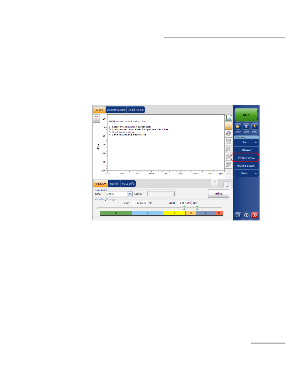
To customize the file name:
1. From the Main Menu, press Preferences.
Using the Autonaming Feature
OSA/OCA 37
Page 44

Preparing Your OSA/OCA for a Test
Using the Autonaming Feature
2. Select the File Name tab.
3. Select which parameters you want to include in the file name from the
list of available choices:
Wavelength/frequency range: current wavelength/frequency
acquisition range.
Acquisition type: current acquisition type.
Scan count: current number of scans in the acquisition tab.
Link ID: prefix value for the link ID configured in the
Preferences-Information tab.
Cable ID: prefix value for the cable ID configured in the
Preferences-General tab.
Fiber ID: prefix value for the fiber ID configured in the
Preferences-General tab.
Location description: location description provided in the
Preferences-Information tab.
38 FTB-5230S/-OCA
Page 45

Preparing Your OSA/OCA for a Test
Using the Autonaming Feature
4. Press the up or down arrows to change the order in which the field
values will appear in the file name.
Based on your selection, a preview of the file name is displayed under
File name preview. The field values are separated with an underscore
( _ ).
5. Press OK to save the changes and close the window, or press Cancel to
exit without saving.
Press Restore Defaults to remove all the changes and apply the default
settings.
The OCA default file name is “Link###”, where ### is an
auto-incrementing number starting at 1 and ending at 999 (after reaching
999, it returns to 1). You can add cable ID and fiber ID information to the
name.
OSA/OCA 39
Page 46

Preparing Your OSA/OCA for a Test
Using the Autonaming Feature
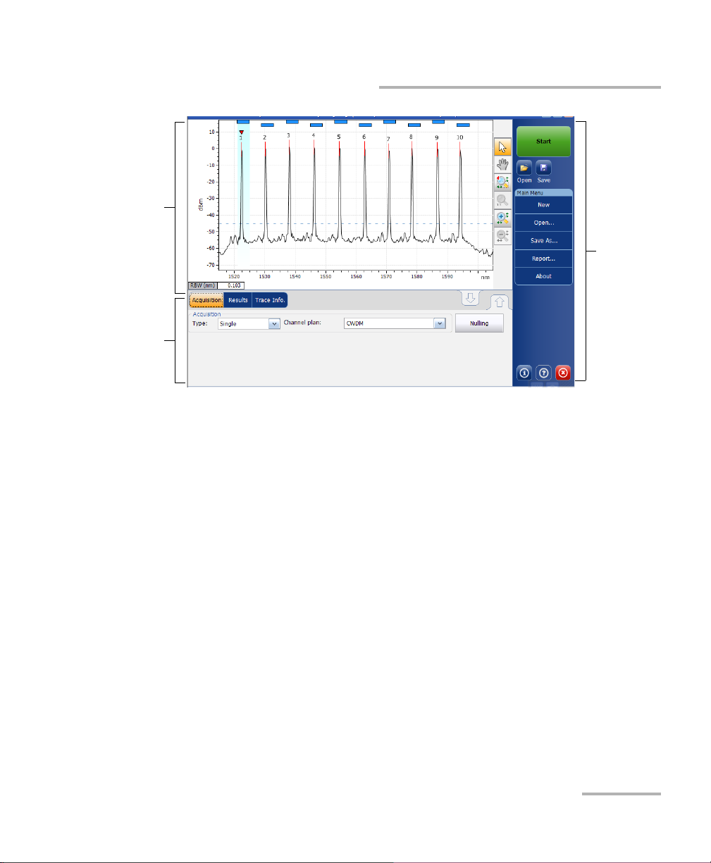
To customize the file name in the OCA application:
1. From the main window, select the Trace Info . tab.
2. Press Trace identification.
3. In the General tab, enter the cable ID and fiber ID information you
want to use.
40 FTB-5230S/-OCA
Page 47

Preparing Your OSA/OCA for a Test
Using the Autonaming Feature
4. Select the Use as template option.
5. Press OK to confirm your choice.
The new default file name will be “CableID_FiberID_Link###”. If you
want to change the word “Link” or the increment number, you can do so in
the Save As window, where the information will be kept for the next time
you save a file.
OSA/OCA 41
Page 48

Page 49

5 Setting Up the Instrument in
WDM Mode
Note: This mode is not available in the OCA application.
Before performing a spectral analysis in the WDM mode, you must set up
the test application with the appropriate parameters, as explained in this
chapter.
Select the WDM test mode as explained in Selecting a Test Mode on
page 20 before setting up the WDM test parameters.
The preferences are the result displayed in the graph and tables, as
well as the job information and related comments saved with each file.
The analysis parameters include the channel list details, pass-fail
threshold settings and allows you to select the noise and power
calculation methods.
The acquisition parameters include the type of measurement you want
to perform and the wavelength range.
See Defining Preferences on page 45, Setting Up WDM Analysis Parameters
on page 61 and Setting Up Acquisition Parameters on page 88 for more
details.
OSA/OCA 43
Page 50

Setting Up the Instrument in WDM Mode
You can set up your unit in different manners, depending on your testing
needs.
The preferred way is to use the complete analysis setup parameters
and complete the information in all tables, as explained in Setting Up
WDM Analysis Parameters on page 61. This setup will be used for the
next acquisition.
The easiest way to set up the instrument, especially when the operator
does not know in advance what to expect at the input of the module is
to use the Discover button. After the Discover button has been
pressed, a measurement and analysis will be performed according to
the best setup determined by the instrument and this setup will be
used for the next scan. This is explained in Using the Discover Feature
on page 155.
The most efficient way to set up the instrument is to use one of the
favorites configurations, uploading a pre-customized acquisition and
analysis setup configuration. The operator in the field only has to press
the button, select the appropriate configuration and press Start. As
an example, a pre-customized configuration could be: “32 channels
DWDM 50GHz”; “Toronto-Montreal CWDM” or “Vendor ABC DWDM
ROADM 40Gb”. This is explained in Managing Favorites on page 163.
You can also import the setup from the current trace. This method will
take the data and channel information from the current trace and
apply them in the corresponding tabs. For more information, see
Setting Up WDM Analysis Parameters on page 61.
44 FTB-5230S/-OCA
Page 51

Setting Up the Instrument in WDM Mode
Defining Preferences
Defining Preferences
The preferences window allows you to set general information and
comments on trace, set display parameters and customize the WDM
results table.
Note: Only the Display and WDM Results tabs are available in offline mode.
Defining Trace Information
The trace information relates to the description of the job to be done, cable
and job IDs, and any relevant information about what is being tested.
To enter general information:
1. From the Main Menu, press Preferences.
OSA/OCA 45
Page 52

Setting Up the Instrument in WDM Mode
Defining Preferences
2. Select the General tab.
3. Define the general parameters as needed.
4. Press OK to save the changes and close the window, or press Cancel to
exit without saving.
Press Clear to clear all the changes made in the General tab.
46 FTB-5230S/-OCA
Page 53

Setting Up the Instrument in WDM Mode
To enter link and location information:
1. From the Main Menu, press Preferences.
2. Select the Information tab.
Defining Preferences
OSA/OCA 47
Page 54

Setting Up the Instrument in WDM Mode
Defining Preferences
3. Under System and link information, define the following parameters
as needed:
Link ID prefix: The prefix value for the link ID. You can enter any
alphanumeric value.
Starting value: The suffix increment starting value for the link ID.
This value is incremented each time a new file is saved provided
the Auto Increment option is selected.
IMPORTANT
If the Auto Increment option is not selected, you have to manually
change the file name when saving the trace file, otherwise the
application will overwrite the previously saved file.
Orientation: The orientation of the link.
System: Information about the system under test.
48 FTB-5230S/-OCA
Page 55

Setting Up the Instrument in WDM Mode
Defining Preferences
4. Under Location Information, define the following parameters as
needed:
Network element: Sets the type of network element.
Test point: Sets the location where the test is performed on the
link.
Description: Enter the description of location if required.
5. Press OK to save the changes and close the window, or press Cancel to
exit without saving.
Press Restore Defaults to remove all the changes and apply the default
values.
OSA/OCA 49
Page 56

Setting Up the Instrument in WDM Mode
Defining Preferences
To enter comments:
1. From the Main Menu, press Preferences.
50 FTB-5230S/-OCA
Page 57

Setting Up the Instrument in WDM Mode
Defining Preferences
2. Select the Comments tab.
3. Enter your comments for the current trace.
4. Press OK to save the changes and close the window, or press Cancel to
exit without saving.
Press Clear to clear all the changes made in the Comments tab.
OSA/OCA 51
Page 58

Setting Up the Instrument in WDM Mode
Defining Preferences
Defining Display Parameters
The application allows you to set display settings for the acquisition trace.
You can set the spectral unit for the trace and the results table. You can also
select the label that should appear on the peaks of the trace.
To define display parameters:
1. From the Main Menu, press Preferences.
52 FTB-5230S/-OCA
Page 59

Setting Up the Instrument in WDM Mode
Defining Preferences
2. Select the Display tab.
3. Select the spectral unit you want to work with, either nm or THz.
OSA/OCA 53
Page 60

Setting Up the Instrument in WDM Mode
Defining Preferences
4. Select the label that will appear on the peaks in the graph, either the
channel name, its number, or nothing.
54 FTB-5230S/-OCA
Page 61

Setting Up the Instrument in WDM Mode
Channel
numbers
Defined channel
names
Defining Preferences
Note: The channel name and channel number cannot be shown at the same
time.
OSA/OCA 55
Page 62

Setting Up the Instrument in WDM Mode
Defining Preferences
5. Select whether you want to show or hide the empty channels from the
channel list in the Results tab.
Note: When selected, empty channels are shown on screen and in the report files.
56 FTB-5230S/-OCA
Page 63

Setting Up the Instrument in WDM Mode
Defining Preferences
6. Select whether you want to show the horizontal markers or the
integrated power and the trace in the marker toolbar.
OSA/OCA 57
Page 64

Setting Up the Instrument in WDM Mode
Defining Preferences
7. Select the background color scheme for the graph as desired.
8. Press OK to save the changes and close the window, or press Cancel to
exit without saving.
Press Restore Defaults to remove all the changes and apply the default
values.
58 FTB-5230S/-OCA
Page 65
Setting Up the Instrument in WDM Mode
Defining Preferences
Customizing WDM Results Table
It is possible to select which results you would like to be displayed in the
Results tab of your WDM tests.
To customize the results table:
1. From the Main Menu, press Preferences.
OSA/OCA 59
Page 66

Setting Up the Instrument in WDM Mode
Defining Preferences
2. Select the WDM Results tab.
3. Select which parameters you want to display in the Results tab from
the list of available choices:
Name: name of channel.
(Center wavelength/frequency): spectral center-of-mass for the
peak in that channel.
Signal Power: signal power for the selected channel (excludes
noise).
OSNR: optical signal to noise ratio, given by Signal power
(according to the current calculation method, in dBm), minus
Noise (according to the current calculation method, in dBm).
Noise: noise level for the selected channel. The type of noise is
indicated in front of the measurement (IEC, Fit).
BW 3.00 dB: bandwidth measured by taking the width of a signal at
50 % linear power of the peak, or -3 dB from the peak.
BW at x dB: bandwidth measured by taking the width of a signal at
x dB from the peak.
60 FTB-5230S/-OCA
Page 67

Setting Up the Instrument in WDM Mode
Setting Up WDM Analysis Parameters
/f : deviation of the spectral center of mass for the peak in that
channel.
/f Peak: spectral peak in that channel.
/f Peak: deviation of the spectral peak in that channel.
4. Press the up or down arrows to change the order in which the columns
will appear in the Results tab.
5. Press OK to save the changes and close the window, or press Cancel to
exit without saving.
Press Restore Defaults to remove all the changes and apply the default
values.
Setting Up WDM Analysis Parameters
This section presents the various analysis settings for the application,
particularly the channel list and settings. You can set the default channel
parameters, channel list, global thresholds, default channel thresholds,
manage favorite configurations and perform user calibration.
Note: When you change the analysis setup parameters, the new settings are
active as soon as you confirm your choice. The current trace is re-analyzed,
and the analysis setup parameters will be applied to the global results and
channel results for the following acquisitions.
You can either set each parameter individually, or use parameters from the
current trace and import them.
OSA/OCA 61
Page 68

Setting Up the Instrument in WDM Mode
Setting Up WDM Analysis Parameters
To import the parameters from the current trace:
1. Make sure that you have a trace on-screen.
2. From the Main Menu, press Analysis Setup.
62 FTB-5230S/-OCA
Page 69

Setting Up the Instrument in WDM Mode
Setting Up WDM Analysis Parameters
3. From any tab, press Import from Trace.
4. Press OK to confirm the changes.
OSA/OCA 63
Page 70

Setting Up the Instrument in WDM Mode
Setting Up WDM Analysis Parameters
Defining General Settings
The general analysis parameters for WDM acquisitions affect the
calculation of the results. Any change you make to the settings affect future
traces, or you can apply them to the active trace when reanalyzing it.
IMPORTANT
In the General tab, you can set the default channel parameters. Any
channel found during an acquisition that is not defined in the
channel list will be analyzed according to the default channel
settings.
To define general settings:
1. From the Main Menu, press Analysis Setup.
64 FTB-5230S/-OCA
Page 71

2. Select the General tab.
Setting Up the Instrument in WDM Mode
Setting Up WDM Analysis Parameters
OSA/OCA 65
Page 72

Setting Up the Instrument in WDM Mode
Setting Up WDM Analysis Parameters
3. Under Default channel settings, define the following parameters as
needed:
Clear the Activate default channel option to use the currently
defined channel list for analysis. This reduces the analysis time by
eliminating the peak detection over the complete spectral range.
The peaks outside the defined channel list will not be analyzed.
66 FTB-5230S/-OCA
Page 73

Setting Up the Instrument in WDM Mode
Setting Up WDM Analysis Parameters
Channel width (GHz or nm): indicates the limit inside which the
power values will be considered in the channel.
For default channels, the channel width that sets the limits of the
channel, should be the same as the channel distance or smaller
(channel distance is defined while creating a channel list). If the
channel width is not compatible with the channel spacing, either a
single peak may be found for two distinct channels and two
analysis would be performed and displayed for that peak, or, it is
possible that two peaks may be found within the same channel
and be considered as one multi-peak signal. With this result, you
can use markers to find the spacing between adjacent channels or
to find the channel width.
Snap to ITU Grid: When selected, each detected peak will be
defined by the nearest ITU channel. The ITU grid is based on the
selected channel width.
Signal power calculation: indicates which calculation method to
apply for signal power value.
Integrated signal power: The integrated signal power represents
the sum of the power values included between the channel limits
of this channel, minus the estimated noise contribution between
the same boundaries. In some cases, for instance CATV signals,
signals with high-frequency modulation, or signals with an
inherent line width similar or larger than the OSA/OCA's resolution
bandwidth, this calculation becomes a better estimation of the
true signal power.
OSA/OCA 67
Page 74

Setting Up the Instrument in WDM Mode
Setting Up WDM Analysis Parameters
Peak signal power: The peak signal power represents the
maximum power value inside the channel. Note that it differs a
little from the peak measurement on the spectrum due to the fact
that the estimated noise is subtracted to get the peak signal power.
Total channel power: The total channel power represents the sum
of the integrated signal power and of the noise within the channel.
The OSNR calculation is not performed when the signal power
calculation type is the total channel power.
Noise for OSNR: indicates which calculation method to use for
OSNR value (InBand and InBand narrow filter are available for
viewing or reanalysis purposes only when opening files from other
OSA models).
Fixed range IEC based (IEC): The IEC method uses the
interpolation of noise measured on both sides of the signal to
estimate the noise level. The position at which the noise is
estimated from the center wavelength is given by the OSNR
distance.
InBand (InB): The InBand method uses a series of scans having
different polarization states to calculate the noise level under the
peak (InBand).
InBand narrow filter (InB nf): The InBand narrow filter method
uses additional processing to provide an accurate OSNR value for
the narrow carved noise. This is because with narrow filters, the
noise level under the peak is not uniform and the OSNR value
depends on the processing width selected.
Fifth order polynomial fit (Fit): The fifth order polyfit method
calculates the noise curve and thus the signal to noise ratio. The
OSA will approximate the noise curve using a fifth order
polynomial fit. This fit definition relies on fit and exclusion zones.
Only the points in the fit zones are used to calculate the fifth order
polynomial fit. If you select the fifth order polyfit method, you have
68 FTB-5230S/-OCA
Page 75

Setting Up the Instrument in WDM Mode
Channel width
Noise
region
OSNR
distance
Exclusion
zone
OSNR
distance
Noise
region
Channel center
Setting Up WDM Analysis Parameters
to define the fit and exclusion zones for your tests using the OSNR
distance and noise region fields. The exclusion zone is indirectly
obtained from the OSNR distance.
OSNR distance (GHz or nm): Except for the fifth order polyfit
selection, the OSNR distance is automatically set at the channel
edge, that is, at half of the channel width from the center
wavelength.
For the fifth order polyfit, the OSNR distance corresponds to the
distance from the channel peak to the center of the fit zone. It is
independent of the channel width.
Noise region: The noise region, or fit zone, defines the region
where the polynomial fit applies. Two identical regions are
centered at the OSNR distance.
OSA/OCA 69
Page 76

Setting Up the Instrument in WDM Mode
Setting Up WDM Analysis Parameters
4. Under Global analysis parameters, define the following parameters
as needed:
Peak detection level (dBm): indicates the minimum power level
from where the peak can be considered as a signal.
RBW for OSNR (nm): indicates the resolution bandwidth selected
for the OSNR calculation. This parameter is generally set to 0.1 nm
to allow for a common basis of comparison between different
OSA/OCAs having different effective resolutions. The instrument’s
RBW value is written below the graph. This parameter does not
actually have an effect on the acquisition, but is only a
normalization factor used to provide the OSNR value in a
standardized manner.
70 FTB-5230S/-OCA
Page 77

Setting Up the Instrument in WDM Mode
Setting Up WDM Analysis Parameters
Wavelength offset (nm): indicates the offset value applied on the
wavelength. This does not replace a calibration performed at
EXFO, but it can help you temporarily sharpen the specifications if
you have determined that, for example, your modules are used
beyond the normal allowed use. Entering a value in THz is not
possible. When an offset is applied, it is indicated at the bottom of
the graph ( ).
Power offset (dB): indicates the offset value applied on the power.
This does not replace a calibration performed at EXFO, but it can
help you achieve the specifications if you have determined that, for
example, your modules are used beyond the normal allowed use.
When an offset is applied, it is indicated at the bottom of the graph
(P ).
To edit the power offset as a tap percentage, press the Edit %
button.
The percentage value entered in Edit percentage will be
converted to a corresponding equivalent value in dB.
Bandwidth at (dB): Set the power level used, relative to the
channel peak power, to compute the second bandwidth result.
5. Press OK to save the changes and close the window, or press Cancel to
exit without saving.
Press Restore Defaults to remove all the changes and apply the default
values.
OSA/OCA 71
Page 78

Setting Up the Instrument in WDM Mode
Setting Up WDM Analysis Parameters
Defining Global Thresholds
Any change you make to the global threshold settings affect future traces,
or you can apply them to the active trace when reanalyzing it.
The application allows you to activate and deactivate the threshold
functionality with a single control. When thresholds are globally enabled,
the results are displayed with the Pass/Fail status based on various settings
(global results, channel results). In addition, a global pass/fail status is also
displayed in the Global Results tab (See Global Results Tab on page 184).
When thresholds are globally disabled, results are displayed without a
Pass/Fail status and the Global pass/fail status will not be active in the
Global Results tab. The P/F column under the results table will not be
displayed.
72 FTB-5230S/-OCA
Page 79

Setting Up the Instrument in WDM Mode
Setting Up WDM Analysis Parameters
You can set your pass/fail threshold limits in different ways depending on
the type of test you are performing.
Threshold Limit Definition
None No threshold limit is set. The results will be displayed without a
Pass/Fail verdict.
Min. only The threshold limit is set for a minimum value only. The
Pass/Fail verdict is declared as Pass (in green), when the value
is equal to or greater than the minimum threshold set. The
verdict is declared as Fail (in red), when the value is below the
minimum threshold set.
Max. only The threshold limit is set for a maximum value only. The
Pass/Fail verdict is declared as Pass (in green), when the value
is equal to or less than the maximum threshold set. The verdict
is declared as Fail (in red), when the value is above the
maximum threshold set.
Min. and Max. The threshold limit is set for the minimum and maximum value.
The Pass/Fail verdict is declared as Pass (in green), when the
value is equal to or within the minimum and maximum
thresholds set. The Pass/Fail verdict is declared as Fail (in red),
when the value is beyond the minimum or maximum
thresholds set.
Use Default When this limit is set, the corresponding threshold set for the
default channels in the Analysis Setup tab will be applied to
the channel.
Max. Deviation The threshold limit is set for the deviation value. The Pass/Fail
verdict is declared as Pass (in green), when the value is equal
to or within the deviation threshold set. The Pass/Fail verdict is
declared as Fail (in red), when the value is beyond deviation
threshold set.
OSA/OCA 73
Page 80

Setting Up the Instrument in WDM Mode
Setting Up WDM Analysis Parameters
To define global thresholds:
1. From the Main Menu, press Analysis Setup.
2. Select the Global Thresholds tab.
74 FTB-5230S/-OCA
Page 81

Setting Up the Instrument in WDM Mode
Setting Up WDM Analysis Parameters
3. Select the Activate all thresholds option to manually set the global
threshold values. If this option is not selected, all the thresholds will be
deactivated, results are displayed without a Pass/Fail status and Global
pass/fail status are not active in the Global Results tab.
4. Enter values in the boxes as explained below:
Average signal power (dBm): the sum of the signal powers of all
the peaks detected in the current acquisition, divided by the total
number of peaks.
Signal power flatness (dB): the difference between the maximum
and minimum signal power values of the detected peaks, in dB.
Average OSNR (dB): the sum of the entire OSNR of the peaks
detected in the current acquisition, divided by the total number of
peaks.
OSNR flatness (dB): the difference between the maximum and
minimum OSNR values of the detected peaks, in dB.
Empty channel count: The number of empty channels from the
channel list.
OSA/OCA 75
Page 82

Setting Up the Instrument in WDM Mode
Setting Up WDM Analysis Parameters
5. Press OK to save the changes and close the window, or press Cancel to
exit without saving.
Press Restore Defaults to remove all the changes and apply the default
values.
Defining Default Thresholds
Default thresholds will be applied to any channel found outside the
channel list during the acquisition or re-analysis.
Note: The default thresholds settings are enabled only when the Activate all
thresholds option is selected in the Global Thresholds tab. For more
information, see Defining Global Thresholds on page 72.
76 FTB-5230S/-OCA
Page 83

Setting Up the Instrument in WDM Mode
Setting Up WDM Analysis Parameters
You can set your pass/fail threshold limits in different ways depending on
the type of test you are performing.
Threshold Limit Definition
None No threshold limit is set. The results will be displayed without a
Pass/Fail verdict.
Min. only The threshold limit is set for a minimum value only. The
Pass/Fail verdict is declared as Pass (in green), when the value
is equal to or greater than the minimum threshold set. The
verdict is declared as Fail (in red), when the value is below the
minimum threshold set.
Max. only The threshold limit is set for a maximum value only. The
Pass/Fail verdict is declared as Pass (in green), when the value
is equal to or less than the maximum threshold set. The verdict
is declared as Fail (in red), when the value is above the
maximum threshold set.
Min. and Max. The threshold limit is set for the minimum and maximum value.
The Pass/Fail verdict is declared as Pass (in green), when the
value is equal to or within the minimum and maximum
thresholds set. The Pass/Fail verdict is declared as Fail (in red),
when the value is beyond the minimum or maximum
thresholds set.
Max. Deviation The threshold limit is set for the deviation value. The Pass/Fail
verdict is declared as Pass (in green), when the value is equal
to or within the deviation threshold set. The Pass/Fail verdict is
declared as Fail (in red), when the value is beyond deviation
threshold set.
OSA/OCA 77
Page 84

Setting Up the Instrument in WDM Mode
Setting Up WDM Analysis Parameters
To define default Thresholds:
1. From the Main Menu, press Analysis Setup.
78 FTB-5230S/-OCA
Page 85

Setting Up the Instrument in WDM Mode
Setting Up WDM Analysis Parameters
2. Select the Default Thresholds tab.
3. Enter values in the boxes as explained below:
Wavelength/Frequency (nm/GHz): the channel’s central
wavelength/frequency.
Signal power (dBm): the signal power for the default channel
(excludes noise).
Noise (dBm): the level of the noise for the selected channel.
OSNR (dB): the optical signal to noise ratio, given by Signal power
(according to the current calculation method, in dBm) minus
Noise (according to the current calculation method, in dBm).
4. Press OK to save the changes and close the window, or press Cancel to
exit without saving.
Press Restore Defaults to remove all the changes and apply the default
values.
OSA/OCA 79
Page 86

Setting Up the Instrument in WDM Mode
Setting Up WDM Analysis Parameters
Managing Channels
Testing DWDM systems involves characterizing multiple signals in a link.
The application allows you to define channels using a channel editor or
quickly generate them from the current data. You can also rapidly create a
list of equally spaced channels. Once a channel list is created, you can
modify it as needed. You can edit the analysis parameters for one channel
or multiple channels.
While creating the channel list, some channels may overlap. When the
channel widths are specified in nm, two channels are considered to be
overlapping when more than 1.2 GHz (approximately) of frequency range
is common between the two channels.
To add a channel list:
1. From the Main Menu, press Analysis Setup.
80 FTB-5230S/-OCA
Page 87
Setting Up the Instrument in WDM Mode
Setting Up WDM Analysis Parameters
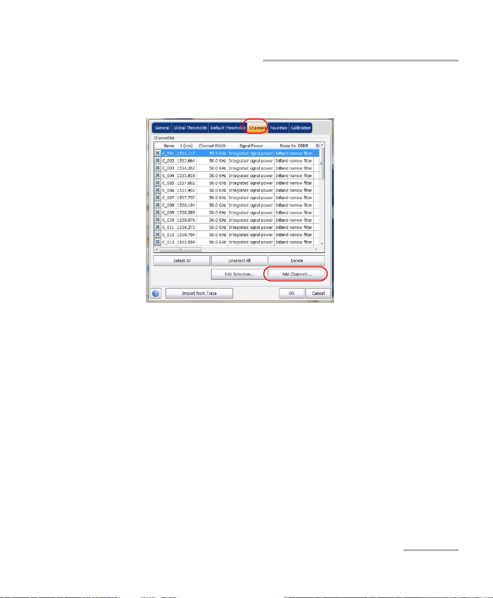
2. Select the Channels tab.
3. By default, the channel list is empty. Press Add Channels.
OSA/OCA 81
Page 88

Setting Up the Instrument in WDM Mode
Setting Up WDM Analysis Parameters
4. Enter values in the boxes as explained below:
Start range (nm or THz): starting range of the channel list.
Stop range (nm or THz): ending range of the channel list.
Channel center wavelength/frequency: spectral center-of-mass for
the peak in that channel.
Note: When using the custom channel center wavelength option, the first channel
will be centered at the Start Range, and the list will be created using
channel distance and channel width.
Channel distance (nm or GHz): distance between channels. The
value of channel distance will be set depending on the selection
made for the channel center wavelength option. The channel
distance box will be enabled only when the channel center
wavelength option is set to custom.
Channel width (nm or GHz): limit inside which the power values
will be considered in the channel. Integrated power is calculated
on channel width.
Name prefix: adds a prefix to the channel names.
82 FTB-5230S/-OCA
Page 89

Setting Up the Instrument in WDM Mode
Setting Up WDM Analysis Parameters
Starting value: sets the increment starting value for the channel
name in the channel list.
Increment value: sets the increment value for the channel name in
the channel list.
5. Press OK to return to the Channels window, which now lists the added
channels.
Note: When new channels are added, the Use Default thresholds selection will
be applied to the channel parameters.
Note: A warning message will be displayed if channels are overlapping, but the
analysis can still be performed on overlapping channels. If any duplicate
channels are added, a confirmation message will be displayed to overwrite
the existing channels with the duplicate channels.
6. Press OK to save the changes and close the window, or press Cancel to
exit without saving.
Note: The application displays a message if more than 1000 channels are added.
You ca n exi t t he Analysis Setup window only after deleting the extra
channels from the channel list. You can delete the channels manually as
required.
OSA/OCA 83
Page 90

Setting Up the Instrument in WDM Mode
Setting Up WDM Analysis Parameters
To edit the parameters of a specific channel:
1. From the Main Menu, press Analysis Setup.
84 FTB-5230S/-OCA
Page 91

Setting Up the Instrument in WDM Mode
Setting Up WDM Analysis Parameters
2. Select the Channels tab.
3. Select the channel or channels to be modified in the channel list.
If you want the changes to be applied to all of your channels, press
Select All. Channels can be selected one by one or all together. You
can press Unselect All to clear all channel selections. To delete the
selected channels, press Delete.
OSA/OCA 85
Page 92

Setting Up the Instrument in WDM Mode
Setting Up WDM Analysis Parameters
4. Press Edit Selection.
86 FTB-5230S/-OCA
Page 93

Setting Up the Instrument in WDM Mode
Setting Up WDM Analysis Parameters
5. Modify the settings as needed. For more information about the settings,
see Defining General Settings on page 64 and Defining Default
Thresholds on page 76. If you leave a box empty, it will remain as it was
before your changes. Modify appropriate settings.
6. Press OK to return to the Channels tab, which now contains the
modified settings.
7. Press OK to save the changes and close the window, or press Cancel to
exit without saving.
OSA/OCA 87
Page 94

Setting Up the Instrument in WDM Mode
Setting Up Acquisition Parameters
Setting Up Acquisition Parameters
Before performing your test, you must set the acquisition type and
parameters.
There are three types of acquisitions in WDM mode:
Single: Spectral measurement is performed once. The results are
displayed according to this measurement.
Averaging: Spectral measurements are performed based on the
number of scans that you have entered for this parameter. The trace
will be displayed after each acquisition and averaged with the previous
traces.
Real-Time: In real-time acquisition, spectral measurements are
performed continuously until you press Stop. No averaging is done for
spectral measurements. The graph and results are refreshed after each
acquisition.
Before performing measurements on an optical spectrum, you must select
the wavelength/frequency range to use. You can perform the scan on the
full range, on spectral bands, or select a custom range.
Note: The shorter the wavelength or frequency range, the faster the acquisition.
88 FTB-5230S/-OCA
Page 95

Setting Up the Instrument in WDM Mode
Setting Up Acquisition Parameters
To set parameters in the Acquisition tab:
1. From the main window, select the Acquisition tab.
2. Select the acquisition type.
OSA/OCA 89
Page 96

Setting Up the Instrument in WDM Mode
Setting Up Acquisition Parameters
3. If you are performing an averaging type acquisition, enter the number
of scans the unit will perform.
4. Select the wavelength range for your acquisition.
You can select the wavelength range by entering the start and stop values
or by selecting a range on the double slider.
To select the wavelength range using the double slider, move the left and
right handles on the double slider or simply click on any band.
Note: You can select more than one adjoining ranges to include in your range, for
example, S + C.
The wavelength range covered within these bands of the spectra are listed
below.
O band (original): 1255 to 1365 nm
E band (extended): 1355 to 1465 nm
S band (short wavelengths): 1455 to 1535 nm
C band (conventional “erbium window”): 1525 to 1570 nm
L band (long wavelengths): 1560 to 1630 nm
U band (ultralong wavelengths): 1620 to 1650 nm.
90 FTB-5230S/-OCA
Page 97

6 Setting Up the Instrument in
Drift Mode
Note: This mode is not available in the OCA application.
Before performing a spectral analysis in the Drift mode, you must set up
the test application with the appropriate parameters, as explained in this
chapter.
Select the Drift test mode as explained in Selecting a Test Mode on page 20
before setting up the Drift test parameters.
The preferences are the result displayed in the graph and tables, as
well as the job information and related comments saved with each file.
The analysis parameters include the channel list details, pass-fail
threshold settings and allows you to select the noise and power
calculation methods.
The acquisition parameters include the type of measurement you want
to perform and the wavelength range.
See Defining Preferences on page 93, Setting Up Drift Analysis Parameters
on page 107 and Setting Up Acquisition Parameters on page 132 for more
details.
OSA/OCA 91
Page 98

Setting Up the Instrument in Drift Mode
You can set up your unit in different manners, depending on your testing
needs.
The preferred way is to use the complete analysis setup parameters
and complete the information in all tables, as explained in Setting Up
Drift Analysis Parameters on page 107. This setup will be used for the
next acquisition.
The easiest way to set up the instrument, especially when the operator
does not know in advance what to expect at the input of the module is
to use the Discover button. After the Discover button has been
pressed, a measurement and analysis will be performed according to
the best setup determined by the instrument and this setup will be
used for the next scan. This is explained in Using the Discover Feature
on page 155.
The most efficient way to setup the instrument is to use one of the
favorites configurations, uploading a pre-customized acquisition and
analysis setup configuration. The operator in the field only has to press
the button, select the appropriate configuration and press Start. As
an example, a pre-customized configuration could be: “32 channels
DWDM 50GHz”; “Toronto-Montreal CWDM” or “Vendor ABC DWDM
ROADM 40Gb”. This is explained in Managing Favorites on page 163.
You can also import the setup from the current trace. This method will
take the data and channel information from the current trace and
apply them in the corresponding tabs. For more information, see
Setting Up Drift Analysis Parameters on page 107.
92 FTB-5230S/-OCA
Page 99

Setting Up the Instrument in Drift Mode
Defining Preferences
Defining Preferences
The preferences window allows you to set general information and
comments on trace, set display parameters and customize the drift results
table.
Note: Only the Display and Drift Results tabs are available in offline mode.
Defining Trace Information
The trace information relates to the description of the job to be done, cable
and job IDs, and any relevant information about what is being tested.
To enter general information:
1. From the Main Menu, press Preferences.
OSA/OCA 93
Page 100

Setting Up the Instrument in Drift Mode
Defining Preferences
2. Select the General tab.
3. Define the general parameters as needed.
4. Press OK to save the changes and close the window, or press Cancel to
exit without saving.
Press Clear to clear all the changes made in the General tab.
94 FTB-5230S/-OCA
 Loading...