

Page 1
FTB-500
User Guide
Page 2

Copyright © 2009–2014 EXFO Inc. All rights reserved. No part of this
publication may be reproduced, stored in a retrieval system or transmitted
in any form, be it electronically, mechanically, or by any other means such
as photocopying, recording or otherwise, without the prior written
permission of EXFO Inc. (EXFO).
Information provided by EXFO is believed to be accurate and reliable.
However, no responsibility is assumed by EXFO for its use nor for any
infringements of patents or other rights of third parties that may result from
its use. No license is granted by implication or otherwise under any patent
rights of EXFO.
EXFO’s Commerce And Government Entities (CAGE) code under the North
Atlantic Treaty Organization (NATO) is 0L8C3.
The information contained in this publication is subject to change without
notice.
Trademarks
EXFO’s trademarks have been identified as such. However, the presence
or absence of such identification does not affect the legal status of any
trademark.
Units of Measurement
Units of measurement in this publication conform to SI standards and
practices.
Version number: 8.0.1.1
ii FTB-500
Page 3

Contents
Certification Information ..................................................................................................... viii
1 Introducing the FTB-500 .............................................................................. 1
Main Features .........................................................................................................................2
LED Indicators Description ......................................................................................................8
Function Buttons Description ................................................................................................11
Power Sources ......................................................................................................................12
Automatic Fan Speed Management ......................................................................................13
Conventions ..........................................................................................................................14
2 Safety Information ..................................................................................... 15
Other Safety Symbols on Your Unit .......................................................................................16
Laser Safety Information .......................................................................................................17
Electrical Safety Information .................................................................................................18
3 Getting Started with Your Unit ................................................................. 23
Grounding Your Unit ............................................................................................................23
Positioning Your Unit ............................................................................................................25
Inserting and Removing Test Modules .................................................................................26
Turning On Your Unit ............................................................................................................32
Turning Off Your Unit .........................................................................................................32
Configuring Your Unit At First Startup ..................................................................................38
Accessing and Exiting ToolBox ..............................................................................................40
Starting Module Applications ...............................................................................................41
Using the On-Screen (Virtual) Keyboard ................................................................................42
Working with Windows 8.1 Pro ............................................................................................42
Right-Clicking with the Touchscreen .....................................................................................44
Installing or Upgrading the Applications ..............................................................................45
Installing EXFO LabVIEW Drivers ...........................................................................................48
Activating Software Options .................................................................................................51
Installing Third-Party Software on Your Unit .........................................................................56
Protecting your Unit with an Antivirus Software ...................................................................56
Securing your Unit Using the Kensington Lock .....................................................................57
Using a Keyboard, Mouse or Other USB Devices ...................................................................58
Configuring an External Monitor ..........................................................................................60
FTB-500 iii
Page 4

4 Setting Up Your FTB-500 .............................................................................63
Adjusting Brightness .............................................................................................................63
Adjusting Microphone and Speaker Volume .........................................................................64
Recalibrating the Touchscreen ..............................................................................................69
Customizing the Right-Click Feature .....................................................................................73
Enabling or Disabling the Automatic Logon .........................................................................77
Selecting the Startup Applications ........................................................................................81
Configuring Network Printers ...............................................................................................83
Selecting the Language of Operation ...................................................................................85
Setting Date and Time Formats .............................................................................................94
Adjusting the Date, Time and Time Zone ..............................................................................96
Configuring the Power Management Options ......................................................................97
Setting ToolBox Behavior ....................................................................................................107
Configuring the Internet Options .......................................................................................109
Configuring Parameters via Windows Mobility Center ........................................................111
Setting Communication Parameters ...................................................................................112
Setting Other Parameters ....................................................................................................112
5 Working with Your Unit ............................................................................113
Printing Documents ............................................................................................................113
Viewing PDF Files ................................................................................................................114
Taking Screen Captures ......................................................................................................115
Browsing the Web ..............................................................................................................117
Accessing the Internet with a 3G USB Modem Key .............................................................118
Retrieving the GPS Location of Your Unit ............................................................................122
Managing Favorites ............................................................................................................124
Using the Calculator ...........................................................................................................132
Using the Text Editor ...........................................................................................................132
Accessing Other Tools .........................................................................................................133
6 Using the Optional Built-In Power Meter and VFL ..................................135
7 Inspecting Fibers with a Probe ................................................................137
8 Managing Data .........................................................................................141
Viewing Disk Space and Managing Files .............................................................................142
Transferring Data via Bluetooth ..........................................................................................143
Connecting to a Wireless Network ......................................................................................150
Using the USB to RS-232 Adapter .......................................................................................152
Freeing Up Disk Space with the Disk Cleanup Utility ...........................................................158
Connecting to a VPN from Your Unit ..................................................................................162
Using Your Unit as an FTP Server ........................................................................................168
iv FTB-500
Page 5

9 Accessing Your Unit Remotely ................................................................. 171
Working with Remote Desktop ...........................................................................................172
Working With TightVNC .....................................................................................................182
Adding Exceptions to the Firewall ......................................................................................188
10 Preparing for Automation ....................................................................... 193
Linking Units with the Ethernet Port ...................................................................................195
Linking Units with the Serial Port ........................................................................................196
Getting Optimum Performance from Your Unit ..................................................................197
Changing Communication Settings ....................................................................................199
Configuring DCOM Access to Your Unit ..............................................................................203
Preparing to Control Modules with a Dedicated Application ..............................................227
11 Using FTB Products in an Automated Test Environment ....................... 231
Standard Status Data Structure ..........................................................................................232
SCPI Command Structure ....................................................................................................236
Consulting Data Types ........................................................................................................239
Writing Remote Control Code .............................................................................................240
Error Message Format .........................................................................................................242
Working with EXFO COM Objects .......................................................................................243
Working with EXFO LabVIEW Drivers ..................................................................................244
Using the EXFO Getting Started Applications .....................................................................246
Building and Using Custom VIs ...........................................................................................251
Monitoring Remote Commands ..........................................................................................258
12 Maintenance ............................................................................................. 263
Cleaning Detector Ports ......................................................................................................264
Cleaning VFL-Type Connectors ............................................................................................265
Cleaning the Touchscreen ...................................................................................................266
Recharging the Batteries .....................................................................................................267
Replacing Batteries .............................................................................................................270
Viewing Battery Status ........................................................................................................276
Recalibrating the Batteries ..................................................................................................278
Installing or Removing the Power Meter and VFL ...............................................................280
Managing Windows Updates .............................................................................................287
Replacing Fuses (Eight-Slot Model Only) .............................................................................289
Recalibrating the Unit .........................................................................................................290
Recycling and Disposal (Applies to European Union Only) ..................................................291
FTB-500 v
Page 6

13 Troubleshooting ........................................................................................293
Solving Common Problems .................................................................................................293
Restoring Your Unit to Normal Operation ...........................................................................299
Accessing the Online Documentation .................................................................................314
Contacting the Technical Support Group ............................................................................315
Viewing System Information ...............................................................................................316
Retrieving Network Interfaces Information .........................................................................319
Transportation ....................................................................................................................322
14 Warranty ....................................................................................................323
General Information ...........................................................................................................323
Liability ...............................................................................................................................324
Exclusions ...........................................................................................................................324
Certification ........................................................................................................................324
Service and Repairs .............................................................................................................325
EXFO Service Centers Worldwide ........................................................................................326
A Technical Specifications ............................................................................327
B Data Types .................................................................................................329
Applicable Data Types for Input—IEEE 488.2 ......................................................................330
Applicable Data Types for Output —IEEE 488.2 ..................................................................339
Applicable Data Types for Input—SCPI ................................................................................349
Special Numeric Values Received on Output .......................................................................350
C IEEE 488.2 and Specific Command Reference .........................................351
IEEE 488.2 Commands–Quick Reference .............................................................................351
IEEE 488.2 Required Commands .........................................................................................352
Specific Commands—Quick Reference ................................................................................372
Specific Commands ............................................................................................................373
D SCPI-Based Errors ......................................................................................391
E COM Properties and Events ......................................................................407
ActiveX (COM/DCOM)—Quick Reference ............................................................................408
Properties ...........................................................................................................................409
Events .................................................................................................................................416
vi FTB-500
Page 7

F Communicating Through TCP/IP over Telnet .......................................... 417
Introducing TCP/IP over Telnet ............................................................................................417
Features ..............................................................................................................................418
Activating TCP/IP over Telnet ...............................................................................................419
Executing SCPI Commands Over Telnet ...............................................................................420
Releasing Modules ..............................................................................................................426
Internal Commands of the TCP/IP over Telnet Protocol .......................................................427
FTB-500 vii
Page 8

Certification Information
Certification Information
North America Regulatory Statement
This unit was certified by an agency approved in both Canada and the
United States of America. It has been evaluated according to applicable
North American approved standards for product safety for use in Canada
and the United States.
Electronic test and measurement equipment is exempt from FCC part 15,
subpart B compliance in the United States of America and from ICES-003
compliance in Canada. However, EXFO Inc. makes reasonable efforts to
ensure compliance to the applicable standards.
The limits set by these standards are designed to provide reasonable
protection against harmful interference when the equipment is operated in
a commercial environment. This equipment generates, uses, and can
radiate radio frequency energy and, if not installed and used in accordance
with the user guide, may cause harmful interference to radio
communications. Operation of this equipment in a residential area is likely
to cause harmful interference in which case the user will be required to
correct the interference at his own expense.
Modifications not expressly approved by the manufacturer could void the
user's authority to operate the equipment.
European Community Declaration of Conformity
An electronic version of the declaration of conformity for your product is
available on our website at www.exfo.com. Refer to the product’s page on
the Web site for details.
viii FTB-500
Page 9

1 Introducing the FTB-500
Today’s network technology is more complex than ever. Thousands of
components have to work in harmony and deployment specialists are
responsible for tuning entire systems for optimal network performance and
for ensuring records updates. In addition, fiber counts are skyrocketing.
DWDM is well entrenched in long-haul applications and is moving into
metro. You know that you need more efficiency.
You will find it with the FTB-500. Benefit from advanced test operations in
outside plant installation, maintenance, and troubleshooting. The FTB-500
streamlines field-based test and measurement operations into a single,
powerful, revolutionary package. Welcome to multi-tasking in the field.
FTB-500 1
Page 10
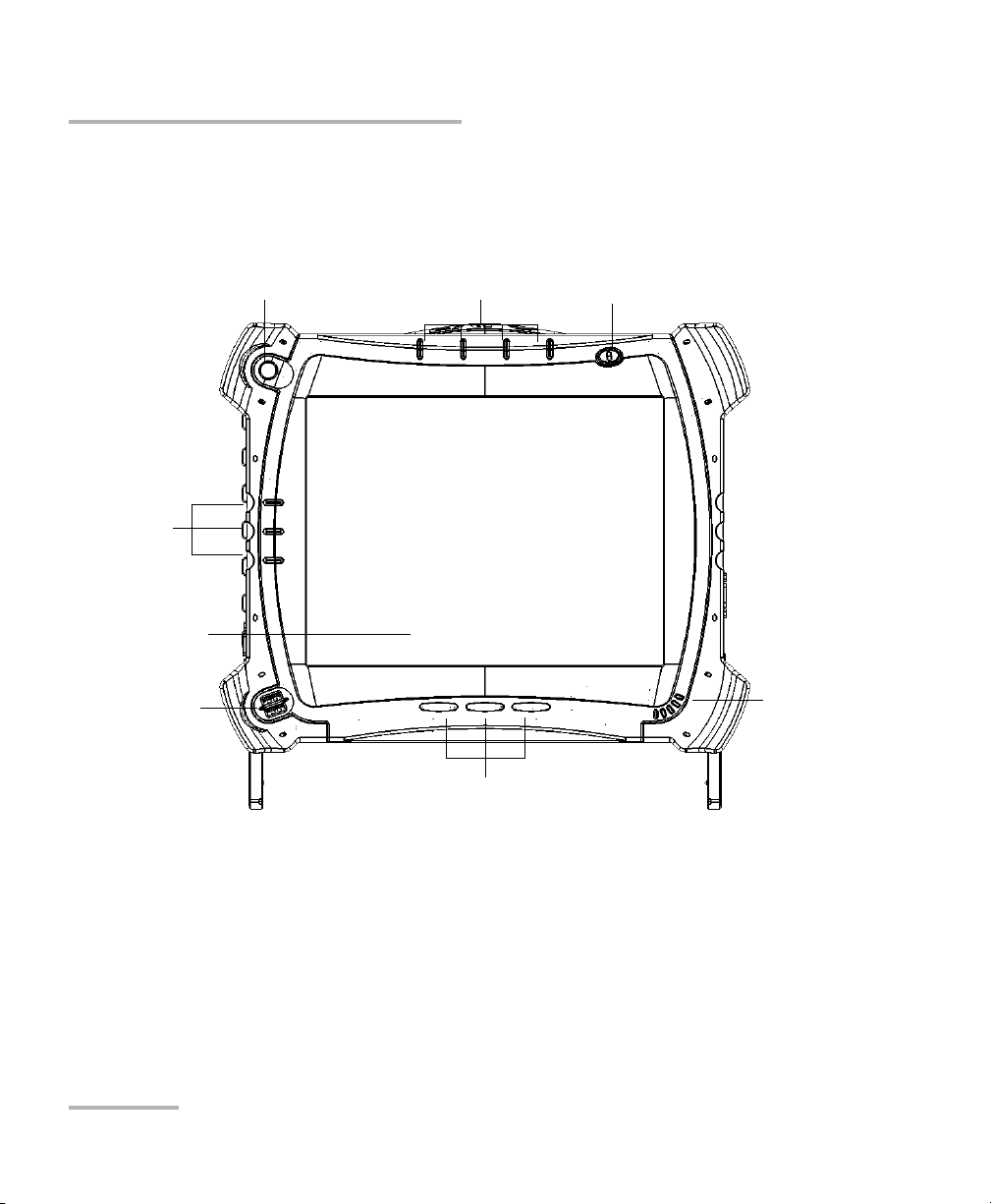
Function buttons
Speaker
Stylus
Power button
LCD/Touchscreen
Module-related LED panel
Unit-related
LED panel
USB ports (2)
Front
Introducing the FTB-500
Main Features
Main Features
2 FTB-500
Page 11
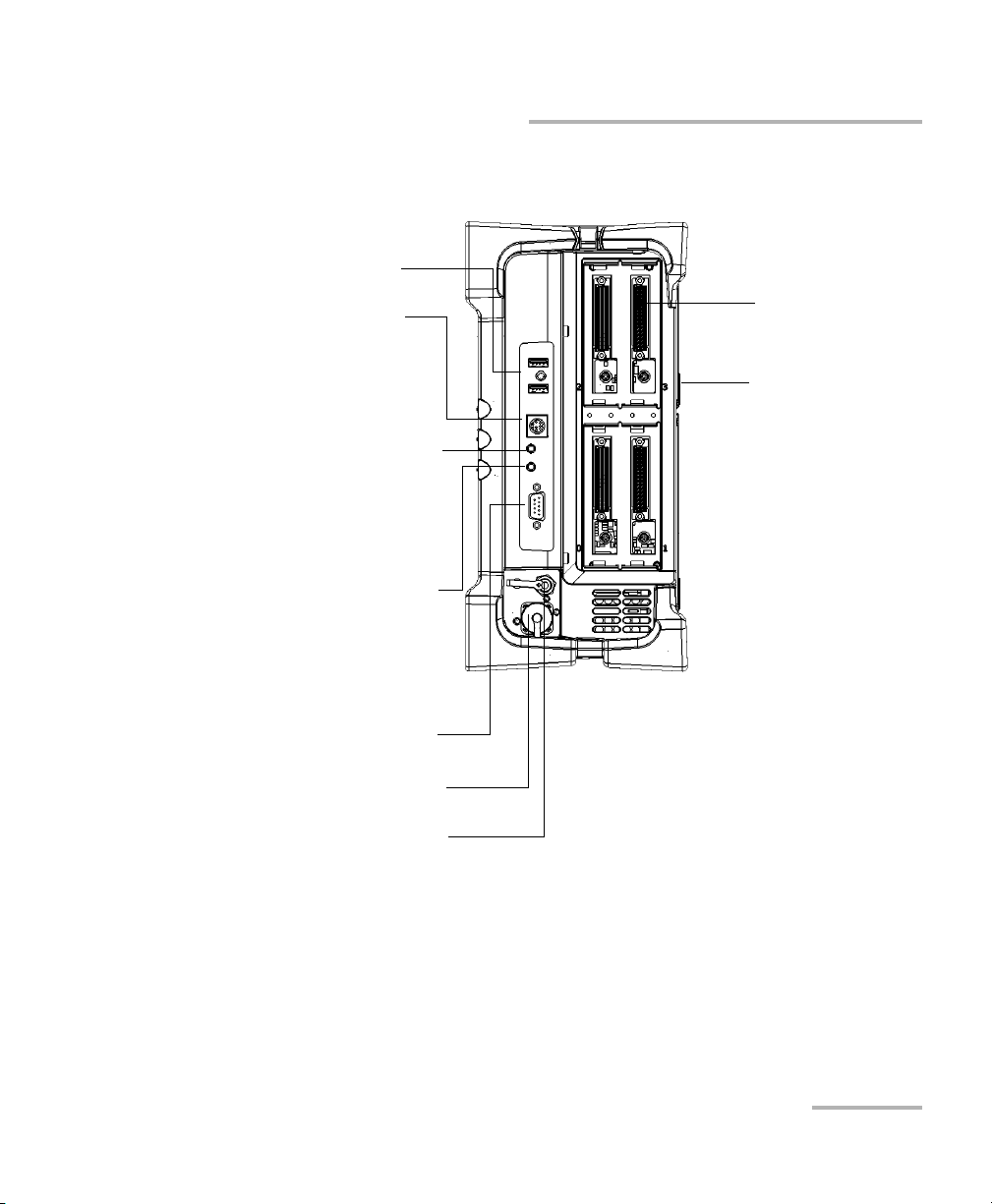
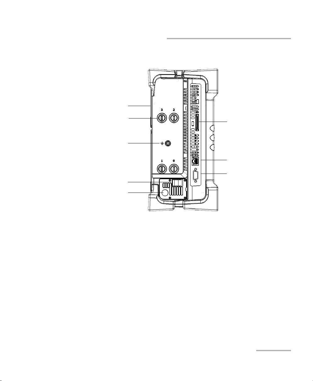
USB ports (2)
Fiber inspection probe connector
Back supports
Right side
(four-slot model)
Module slots
Serial port (male DB-9)
Audio in port
(for any commercially available
microphone and having a 3.5 mm
connector)
Audio out port
(for any commercially available speaker
or headset, and having a 3.5 mm
connector)
Power meter (optional)
VFL port (optional);
laser radiation emitted at this port
when VFL is active
Introducing the FTB-500
Main Features
FTB-500 3
Page 12
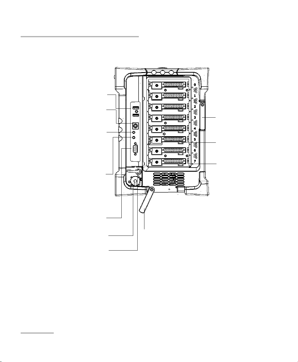
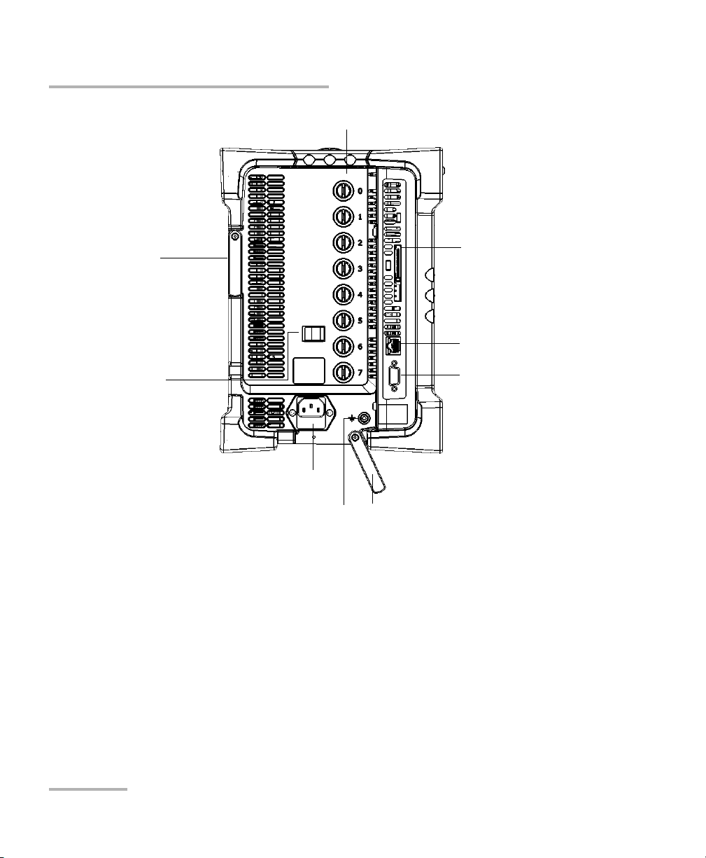
Introducing the FTB-500
Back support
Right side
(eight-slot model)
Module slots
Bottom support
Front module lock
USB ports (2)
Serial port (male DB-9)
Fiber inspection probe connector
Audio in port
(for any commercially available
microphone and having a 3.5 mm
connector)
Audio out port
(for any commercially available speaker
or headset, and having a 3.5 mm
connector)
Power meter (optional)
VFL port (optional);
laser radiation emitted at this port
when VFL is active
Main Features
4 FTB-500
Page 13
Back supports
DC input connector
(for AC adapter/charger)
Ethernet (RJ-45) port
Video out port (for any
commercially available
monitor supporting a
minimum resolution of
1024 x 768 (Extend
displays setting))
Module retaining screws
Left side
(Four-slot model)
ExpressCard slot (for Wi-Fi
or memory cards having a
34-mm format)
Telecom grounding
terminal
Cable strain relief
Introducing the FTB-500
Main Features
FTB-500 5
Page 14
Introducing the FTB-500
Back support
AC connector
Bottom support
Ethernet (RJ-45) port
Video out port (for any
commercially available
monitor supporting a
minimum resolution of
1024 x 768 (Extend displays
settings))
Module retaining screws
Left side
(Eight-slot model)
ExpressCard slot (for any
commercially available Wi-Fi
or memory cards having a
34-mm format)
Cable strain relief
Telecom grounding terminal
Main Features
6 FTB-500
Page 15
Introducing the FTB-500
Main Features
The FTB-500 runs Microsoft Windows 8.1 Pro, and the ToolBox software
provides you with a graphical, user-friendly interface for your testing
applications.
The interface is easy to access, whether you are using the touchscreen or a
mouse and a keyboard.
ToolBox brings multitasking to field testing. You can perform different tests
and work on tests results all at the same time, switching between
applications easily.
The FTB-500 supports local control (via the ToolBox software) and remote
control (through RS-232 or Ethernet TCP/IP—using SCPI commands or the
provided LabVIEW drivers).
Note: LabVIEW drivers may not be available for some modules.
Note: In this documentation, the words “tap” and “double-tap” (related to the
use of a touchscreen) replace the words “click” and “double-click”.
FTB-500 7
Page 16
Introducing the FTB-500
LED Indicators Description
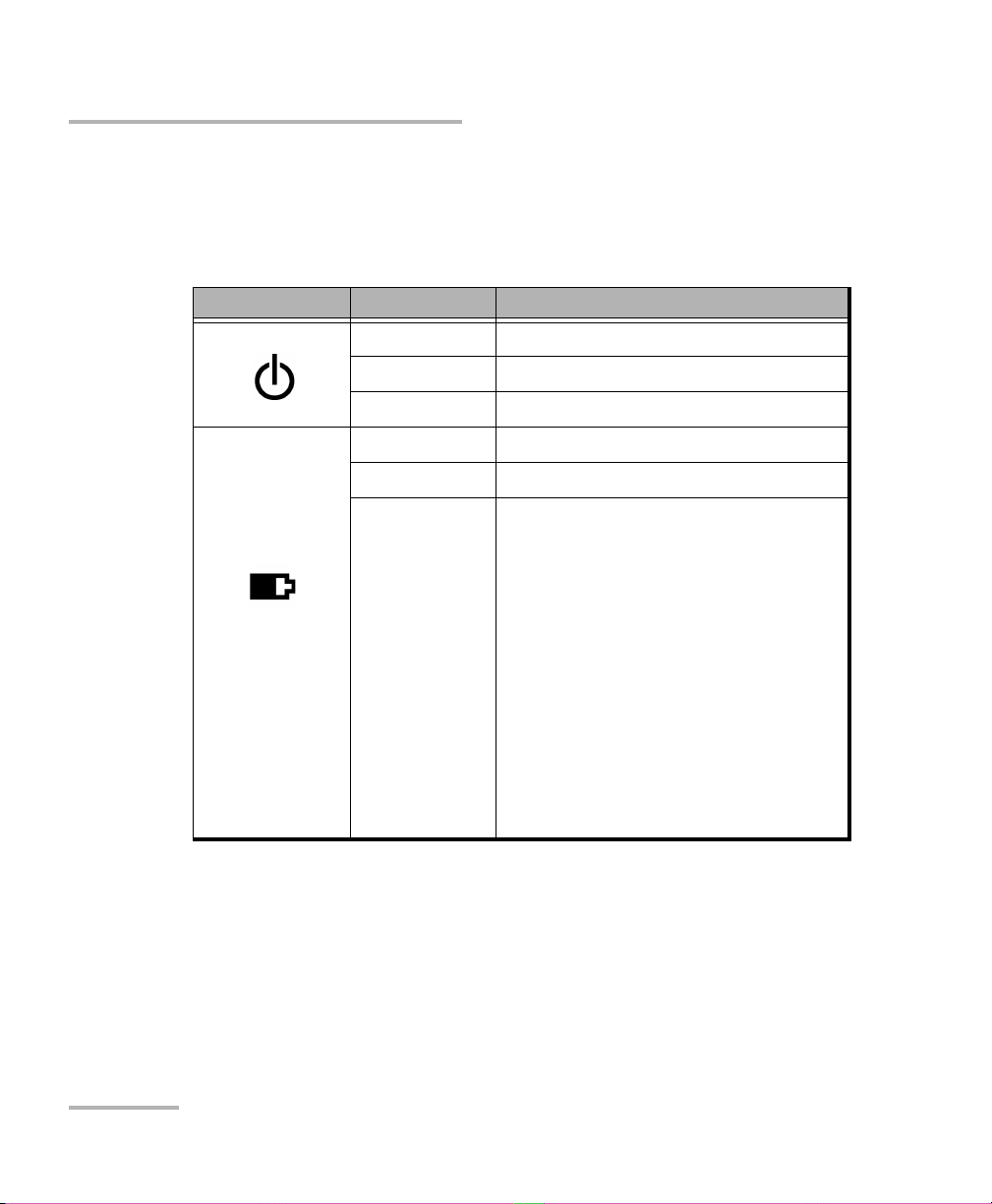
LED Indicators Description
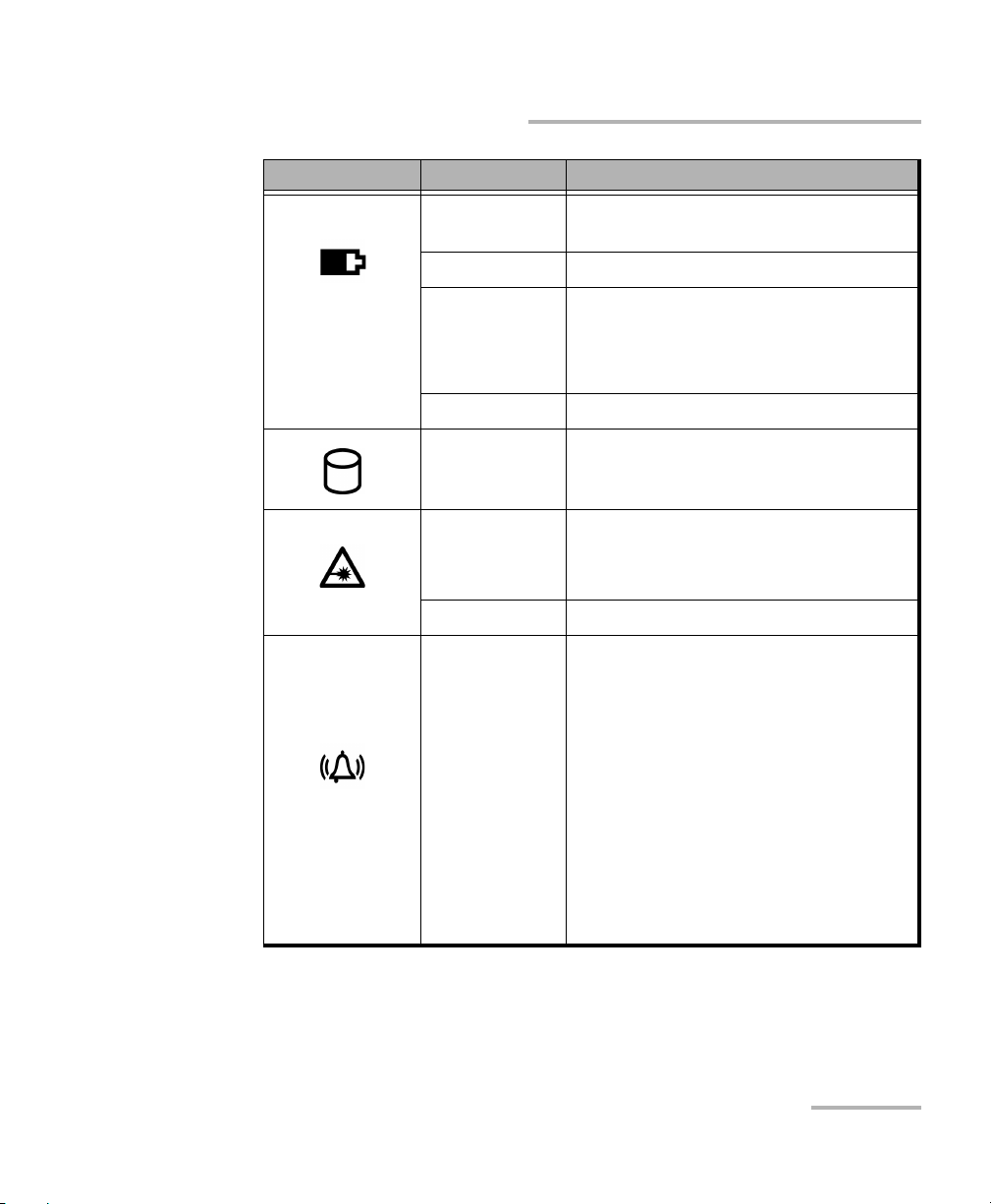
The LED panel on the front of the unit provides you with the status of the
FTB-500.
LED Status Meaning
Green Unit is on.
(when unit is
connected to an
external power
source)
Green, blinking Unit is in Sleep mode.
Off Unit is off or in Hibernation mode.
Green All batteries are fully charged.
Green, blinking At least one battery is charging.
Yellow, blinking No battery present in the unit.
OR
The unit and its modules would be
using more power than what is
available from batteries. Do not
disconnect AC power while this
module is in use.
A blinking yellow LED takes
precedence over a blinking green one,
so when AC power is connected, even
if the LED is blinking yellow, batteries
are probably charging (depending on
conditions).
8 FTB-500
Page 17
LED Status Meaning
Off The global level of the batteries is
above the “low-battery threshold”.
Yellow The global level of batteries is low.
(when unit is not
connected to an
external power
source)
Yellow, blinking The unit and its modules would be
using more power than what is
available from batteries. Connect AC
power as soon as possible.
Red Battery error. Contact EXFO.
Lit Hard disk read or write operations
Red, blinking Laser status LED.
At least one module emits an optical
signal.
Off No modules emit signal.
Introducing the FTB-500
LED Indicators Description
Va r i ed
Each application using the alarm
LED provides its alarm level to the
platform when needed
(Red/Yellow/Green/OFF).
If more than one application uses
the alarm LED, the LED is displayed
using the color of the most severe
alarm with red as the most severe,
followed by yellow and finally
green.
If more than one application uses
the alarm LED, the LED is blinking.
FTB-500 9
Page 18
Introducing the FTB-500
LED Indicators Description
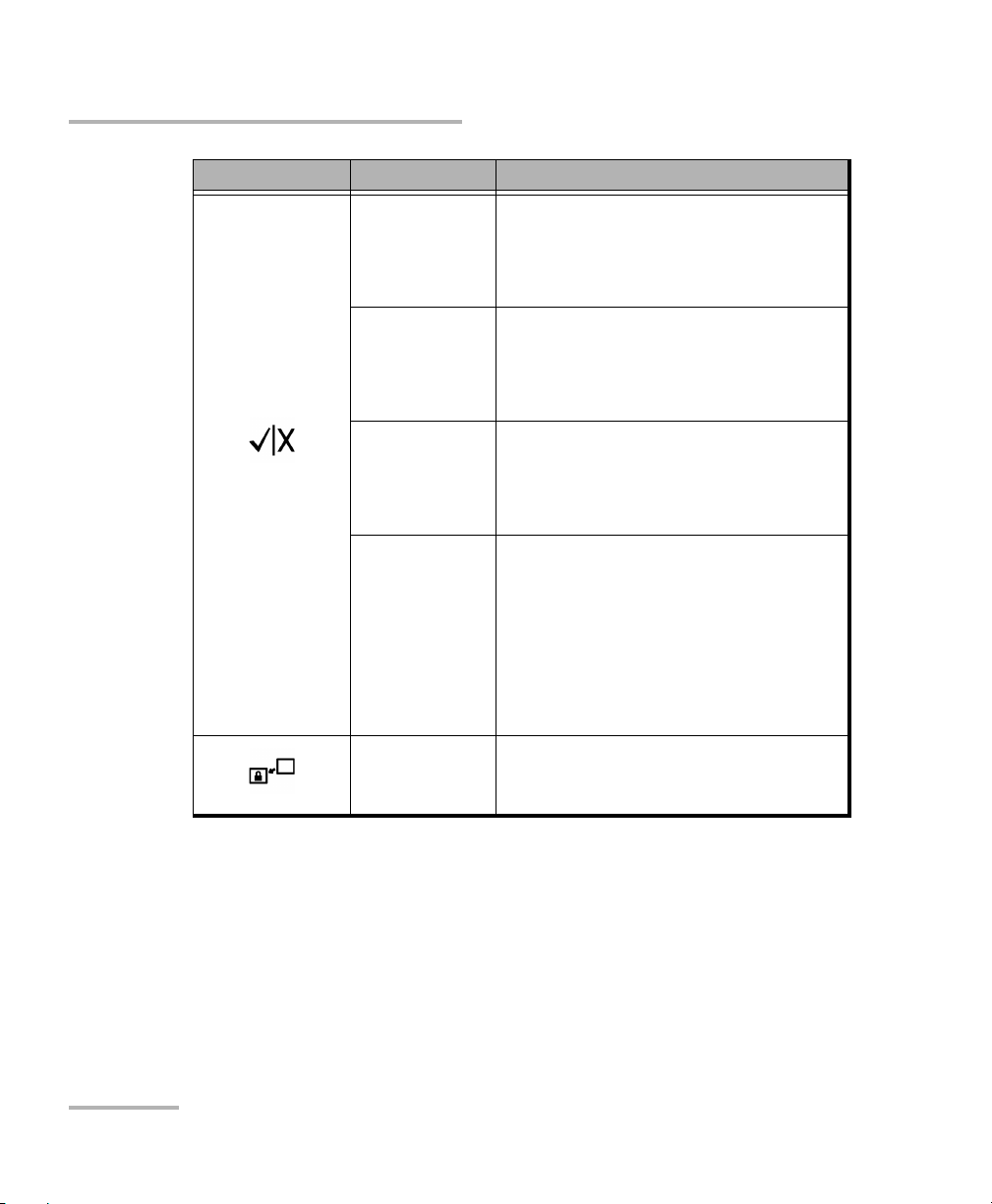
LED Status Meaning
Green Result status from application currently
displayed.
Pass (result does not exceed the
defined threshold).
Green, blinking Result statuses from two or more
applications.
Pass (no results exceed the defined
threshold).
Red Result status from application currently
displayed.
Fail (result exceeds the defined
threshold).
Red, blinking Result statuses from two or more
applications.
Fail (all results exceed the defined
threshold).
OR
Mixed statuses (some are Pass and
some are Fail).
Green Unit is controlled remotely.
10 FTB-500
Page 19
Introducing the FTB-500
Function Buttons Description
Function Buttons Description
The FTB-500 is equipped with function buttons that give you access to
features at all times.
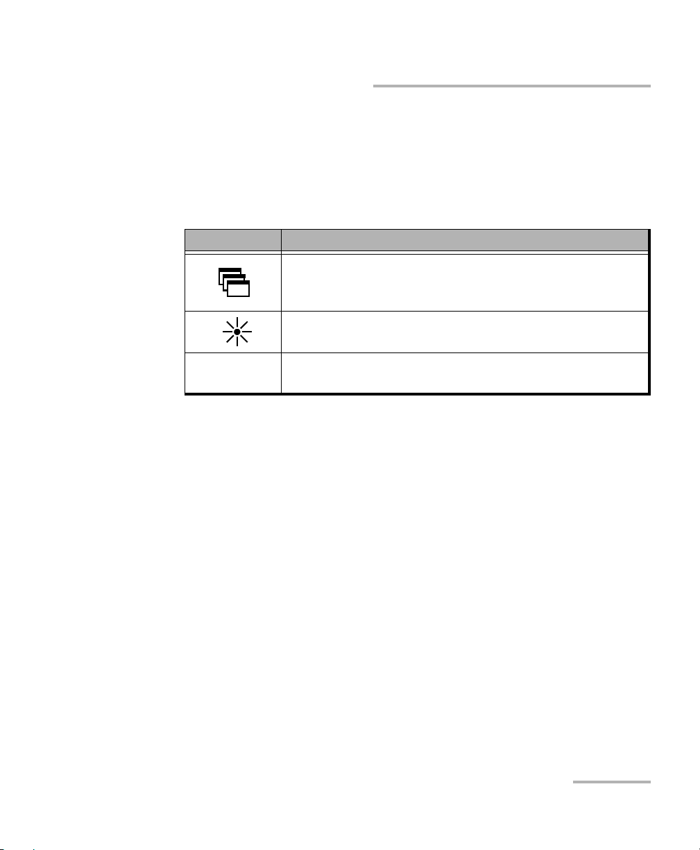
The table below shows an overview of their purpose.
Button Purpose
To show the taskbar, from which you can switch among
running applications, select a keyboard, view battery
information, view the time and date, etc.
To set the display brightness level. For more information,
see Adjusting Brightness on page 63.
LOCAL
When you are working in remote control mode, to return
to local control and settings.
FTB-500 11
Page 20

Introducing the FTB-500
Pow er So urces
Power Sources
Your unit operates with the following power sources:
Indoor use only: AC adapter/charger (four-slot model) or standard
three-wire power cord (eight-slot model) connected to standard
power outlet.
When it is connected to an external power source, the unit will
function even if the batteries are not present.
Indoor and outdoor use: Lithium-ion rechargeable batteries
(automatically take over if you disconnect the unit from its external
power source). The number of batteries that power your unit and that
come with it depends on the model that you have purchased. There
are two batteries for the four-slot model, and three batteries for the
eight-slot model.
Possible to switch from an external power source to battery power
or vice versa without affecting operation.
The battery recharges automatically when the unit is connected to
an external power source (with the AC adapter/charger or the
three-wire power cord).
For more information, see Electrical Safety Information on page 18.
12 FTB-500
Page 21

Introducing the FTB-500
Automatic Fan Speed Management
Automatic Fan Speed Management
The FTB-500 will determine the most appropriate fan speed, depending on
the power requirements and the type of modules you are using.
IMPORTANT
Fan speed is always determined to cool down the most
heat-generating modules.
If the temperature keeps rising and reaches the limit: your FTB-500 will
turn off to protect both the modules and the platform itself.
CAUTION
Make sure to use protective covers over empty slots in your
four-slot model to avoid overheating.
FTB-500 13
Page 22

Introducing the FTB-500
Conventions
Conventions
Before using the product described in this guide, you should understand
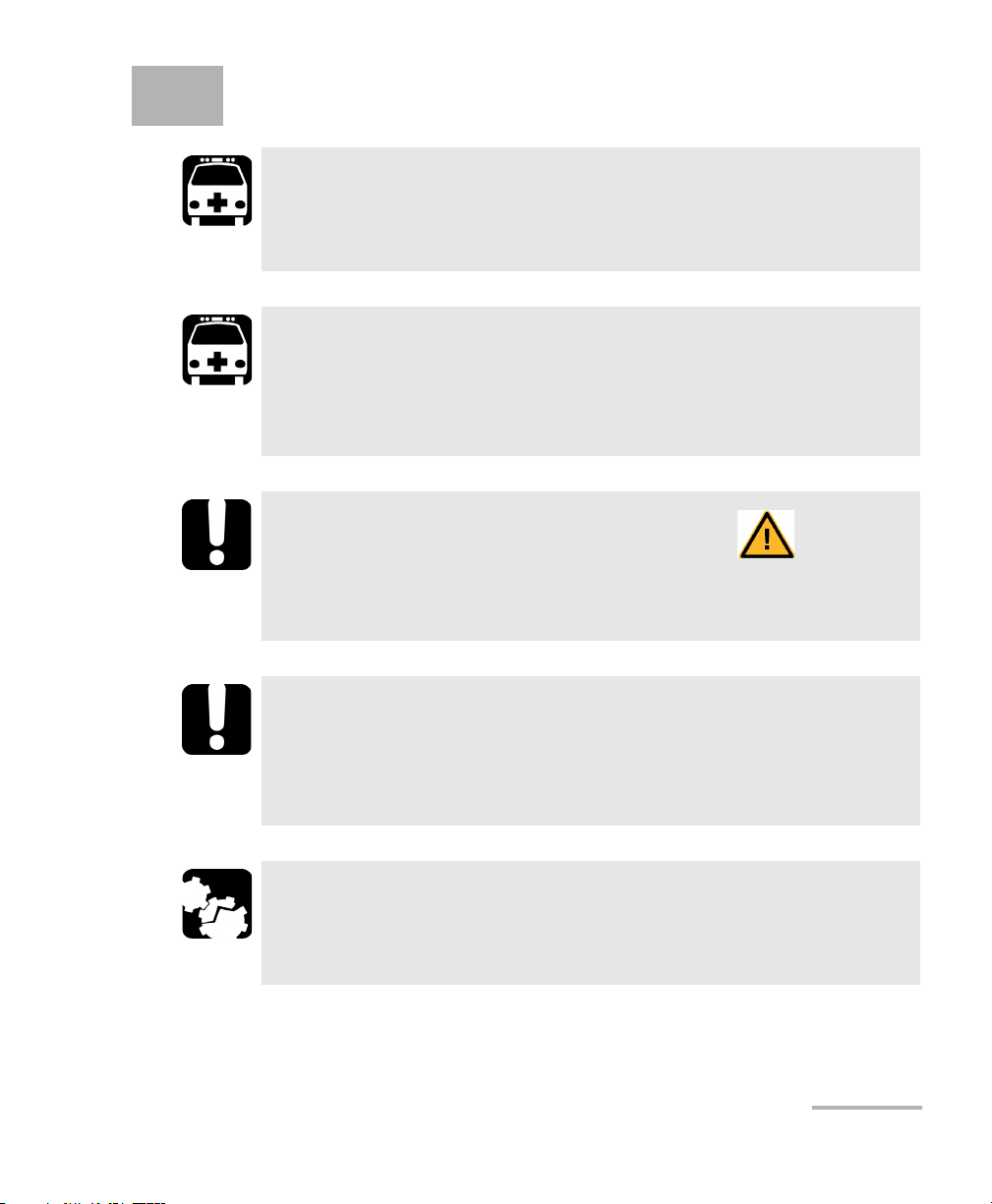
the following conventions:
Indicates a potentially hazardous situation which, if not avoided,
could result in death or serious injury. Do not proceed unless you
understand and meet the required conditions.
Indicates a potentially hazardous situation which, if not avoided,
may result in minor or moderate injury. Do not proceed unless you
understand and meet the required conditions.
Indicates a potentially hazardous situation which, if not avoided,
may result in component damage. Do not proceed unless you
understand and meet the required conditions.
WARNING
CAUTION
CAUTION
IMPORTANT
Refers to information about this product you should not overlook.
14 FTB-500
Page 23
2 Safety Information
WARNING
Do not install or terminate fibers while a light source is active.
Never look directly into a live fiber and ensure that your eyes are
protected at all times.
WARNING
The use of controls, adjustments and procedures, namely for
operation and maintenance, other than those specified herein may
result in hazardous radiation exposure or impair the protection
provided by this unit.
IMPORTANT
When you see the following symbol on your unit , make sure
that you refer to the instructions provided in your user
documentation. Ensure that you understand and meet the required
conditions before using your product.
IMPORTANT
Other safety instructions relevant for your product are located
throughout this documentation, depending on the action to
perform. Make sure to read them carefully when they apply to your
situation.
CAUTION
When the laser safety light is flashing, at least one module is
emitting an optical signal. Please check all modules, as it might not
be the one you are currently using.
FTB-500 15
Page 24
Safety Information
Other Safety Symbols on Your Unit
Other Safety Symbols on Your Unit
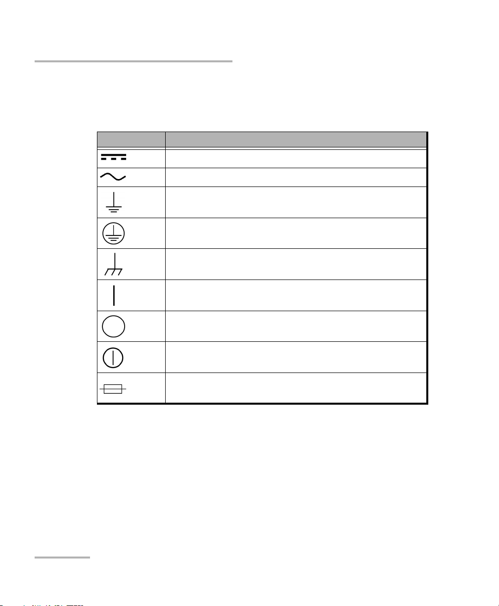
One or more of the following symbols may also appear on your unit.
Symbol Meaning
Direct current
Alternating current
The unit is equipped with an earth (ground) terminal.
The unit is equipped with a protective conductor terminal.
The unit is equipped with a frame or chassis terminal.
On (Power)
Off (Power)
On/Off (Power)
Fuse
16 FTB-500
Page 25
Safety Information
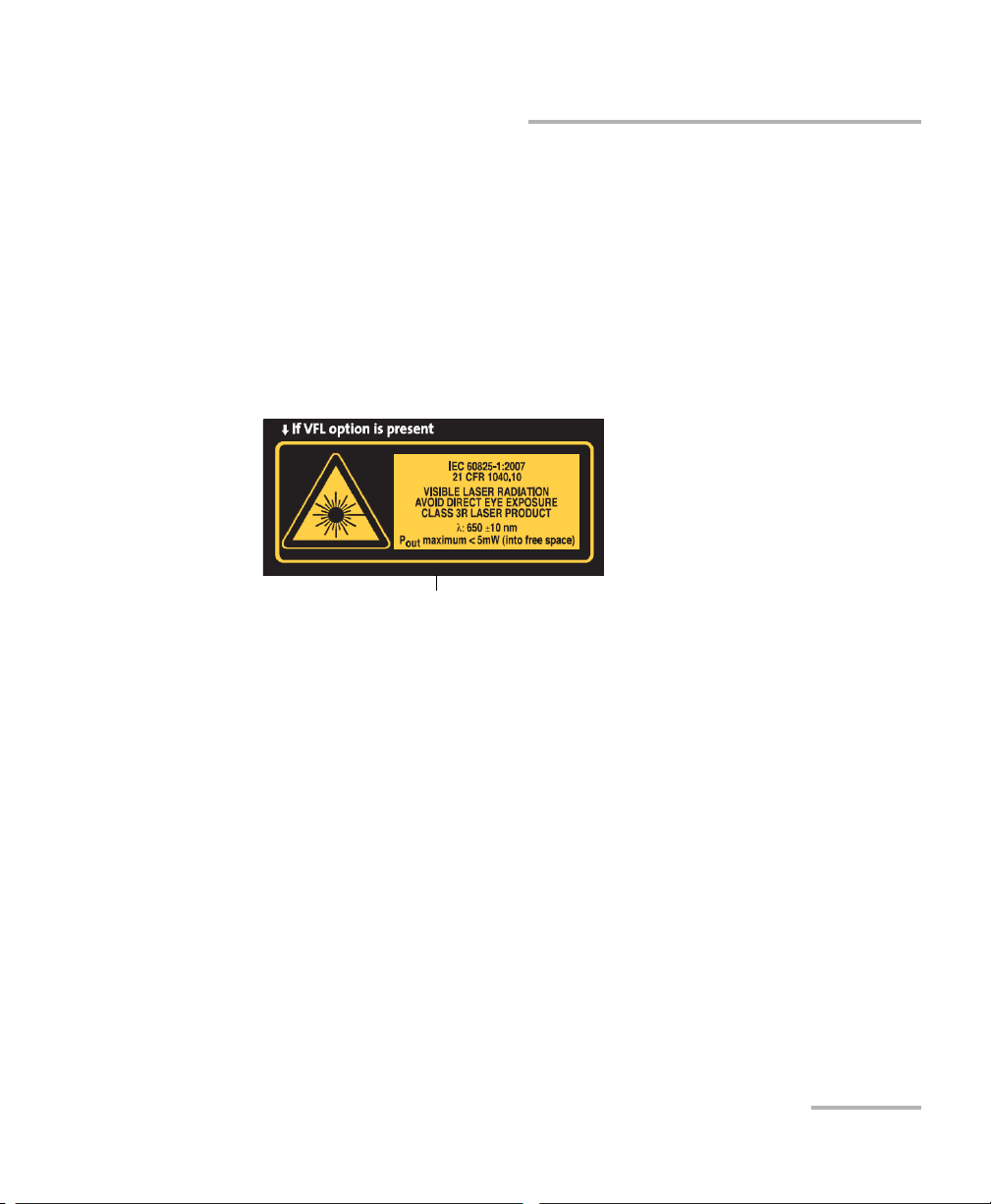
Affixed to back panel of unit.
Laser Safety Information
Laser Safety Information
Units with Built-In VFL
Your instrument is a Class 3R laser product in compliance with standards
IEC 60825-1: 2007 and 21 CFR 1040.10, except for deviations pursuant to
Laser Notice No. 50, dated June 24, 2007. Laser radiation is emitted at the
output port. It is potentially harmful in direct intrabeam viewing.
The following label(s) indicate that the product contains a Class 3R source:
The modules that you use with your unit may have different laser classes.
Refer to the user guide or the online help of the different modules for the
exact information.
Units without Built-In VFL
If your unit is not equipped with a VFL, the laser class of your unit depends
on the modules that you use. Refer to the user guide or the online help of
the different modules for the exact information.
FTB-500 17
Page 26

Safety Information
Electrical Safety Information
Electrical Safety Information
The four-slot model uses an external AC/DC adapter connected to an
international safety standard three-wire power cable.
The eight-slot model uses an international safety standard three-wire
power cable. This cable serves as a ground when connected to an
appropriate AC power outlet.
Note: If you need to ensure that the unit is completely turned off, disconnect the
power cable and remove the batteries.
WARNING
Insert the power cable plug into a power outlet with a
protective ground contact. Do not use an extension cord
without a protective conductor.
Before turning on the unit, connect all grounding terminals and
extension cords to a protective ground via a ground socket. Any
interruption of the protective grounding is a potential shock
hazard and may cause personal injury. Whenever the ground
protection is impaired, do not use the unit and secure it against
any accidental operation.
Do not tamper with the protective ground terminal.
18 FTB-500
Page 27

Safety Information
Electrical Safety Information
The color coding used in the electric cable depends on the cable. New
plugs should meet the local safety requirements and include:
adequate load-carrying capacity
ground connection
cable clamp
WARNING
Never connect the unit to the AC mains (with the
adapter/charger, or directly with a power cord) when it is used
outdoors.
Position the unit so that the air can circulate freely around it.
Operation of any electrical instrument around flammable gases
or fumes constitutes a major safety hazard.
To avoid electrical shock, do not operate the unit if any part of
the outer surface (covers, panels, etc.) is damaged.
Only authorized personnel should carry out adjustments,
maintenance or repair of opened units under voltage. A person
qualified in first aid must also be present. Do not replace any
components while the power cable and batteries are connected.
(Eight-slot model only) Use only fuses with the required rated
current and specified type (F6.3A L, 5 mm x 20 mm (0.197 in x
0.787 in), fast-acting, low-breaking capacity, 250 V). Do not use
repaired fuses or short-circuited fuse holders.
Unless otherwise specified, all interfaces are intended for
connection to Safety Extra Low Voltage (SELV) circuits only.
Capacitors inside the unit may be charged even if the unit has
been disconnected from its electrical supply.
FTB-500 19
Page 28

Safety Information
Electrical Safety Information
WARNING
Use only the listed and certified AC adapter/charger provided by
EXFO with your unit (four-slot model). It provides reinforced
insulation between primary and secondary, and is suitably rated
for the country where the unit is sold.
Use only accessories (such as the batteries, and fiber inspection
probe) designed for your unit and approved by EXFO. For a
complete list of accessories available for your unit, refer to its
technical specifications.
When you use the unit outdoors, ensure that it is protected
from liquids, dust, direct sunlight, precipitation, and full wind
pressure.
Equipment Ratings
Tem pe rat ur e
Operation unit powered by batteries: 0 °C to 50 °C
122 °F)
(total max. of 50 W for modules in four-slot model)
(total max. of 85 W for modules in eight-slot model)
unit connected to AC power:
0 °C to 40 °C (32 °F to 104 °F)
(total max. of 100 W for modules
in four-slot model)
a
(32 °F to
0 °C to 50 °C (32 °F to 122 °F)
(total max. of 200 W for modules
in eight-slot model)
Storage unit: –40 °C to 70 °C (–40 °F to 158 °F)
Relative humidity
20 FTB-500
b
unit: 95 % non-condensing
AC adapter: 10 % to 80 % non-condensing
Page 29
Safety Information
Electrical Safety Information
Equipment Ratings
Maximum operation altitude 2000 m (6562 ft) (unit connected to external power
supply)
5000 m (16405 ft) (unit operated from batteries)
Pollution degree
2 (unit connected to external power supply)
3 (unit operated from batteries)
c
Overvoltage category unit: I
AC adapter: II
Measurement category Not rated for measurement categories II, III, or IV
Input power
d
unit (four slots): 24 V; 8 A
AC adapter (four slots):
100 - 240 V; 50/60 Hz; 4.8 A
unit (eight slots): 100 - 240 V; 50/60 Hz; 4.8 A
a. With some modules, the maximum operation temperature is 40 °C (104 °F).
b. Measured in 0 °C to 31 °C (32 °F to 87.8 °F) range, decreasing linearly to 50 % at 40 °C (104 °F).
c. Equipment must be normally protected against exposure to direct sunlight, precipitation and full wind
pressure.
d. Not exceeding ± 10 % of the nominal voltage.
CAUTION
The use of voltages higher than those indicated on the label affixed
to your unit may damage the unit.
IMPORTANT
The operation and storage temperatures of some modules may
differ from the temperatures specified for your platform. In this
case, always ensure that you comply with the most restrictive
conditions (either module or platform).
FTB-500 21
Page 30

Page 31

3 Getting Started with Your Unit
Grounding Your Unit
When you perform outside plant tests with certain modules, you may want
to ground your unit because it can be exposed to overvoltages from the
telecommunication network. Refer to the user documentation that comes
with your modules to know if you need to ground your unit.
WARNING
Not grounding your unit when it is recommended may cause
serious injuries to communication network staff or other users.
Ensure to ground the unit using a grounding method that
complies with your local regulations. If you are not sure on how
to proceed, consult a certified electrician.
Note: To ground your unit, you need a grounding wire (18 AWG minimum) with a
U-shaped terminal.
FTB-500 23
Page 32

Getting Started with Your Unit
Eight-slot modelFour-slot model
Grounding Your Unit
To ground your unit:
1. Position the unit so that you can see its left panel.
2. Place the U-shaped terminal under the grounding stud’s screw head.
3. Turn the grounding stud clockwise to screw it tight.
4. Ground the other end of the wire as per your local regulation.
Your unit is now grounded properly.
24 FTB-500
Page 33

Getting Started with Your Unit
Four-slot model
There are two sets of stands on the
back of the unit with different
lengths. Select the one that provides
you with the best angle.
Back
support
Bottom support
Eight-slot model
Positioning Your Unit
Positioning Your Unit
You can change the orientation of your unit with the bottom or back
supports.
To position the unit using the supports:
Pull out the support pair that will provide you with the best viewing angle
according to your situation.
IMPORTANT
The supports should always be used in order to ensure that the unit
is stable during your tests and will not fall down to cause damage
to the test components or injure you.
FTB-500 25
Page 34

Getting Started with Your Unit
Inserting and Removing Test Modules
Inserting and Removing Test Modules
Never insert or remove a module while the FTB-500 is turned on.
This will result in immediate and irreparable damage to both the
module and unit.
To avoid damaging your unit, use it only with modules approved by
EXFO.
When the laser safety LED ( ) is flashing on the FTB-500, at least
one of your modules is emitting an optical signal. Please check all
modules, as it might not be the one you are currently using.
CAUTION
CAUTION
WARNING
To insert a module into the FTB-500:
1. Exit ToolBox and turn off your unit (shut down, not hibernate or sleep).
2. Position the FTB-500 so that its right panel is facing you.
3. Take the module and place it so that the connector pins are at the
back, as explained and shown below.
CAUTION
Inserting a module upside down could result in permanent damage
to the module, as the connector pins might be bent.
26 FTB-500
Page 35

Getting Started with Your Unit
Protruding edges
on right side
Identification sticker
on left side
Connector pins
at the back
Retaining
screw hole
at the back
FTB-500 right panel
Protruding edges
on bottom
Identification sticker
facing up
Connector
pins at the
back
Retaining screw
hole at the
back
FTB-500 right panel
Inserting and Removing Test Modules
(4-slot model) identification sticker must be on left side and
retaining screw hole under connector pins.
(eight-slot model) identification sticker must be facing up and
connector pins at the right of the retaining screw hole.
FTB-500 27
Page 36

Getting Started with Your Unit
Turn retaining screw knob
clockwise
FTB-500 left panel
Inserting and Removing Test Modules
Note: If you are using larger or heavier modules, place them near the bottom of
the unit as much as possible.
4. Insert the protruding edges of the module into the grooves of the
receptacle’s module slot.
5. Push the module all the way to the back of the slot, until the retaining
screw makes contact with the receptacle casing.
6. Place the unit so that its left panel is facing you.
7. While applying slight pressure to the module, turn the retaining screw
clockwise until it is tightened.
This will secure the module into its “seated” position.
28 FTB-500
Page 37

Getting Started with Your Unit
Inserting and Removing Test Modules
8. If you are using a larger or heavier module, use a front module lock to
hold them securely in place. Simply place the retaining part against the
module, then screw in the holding pin.
When you turn on the unit, the startup sequence will automatically detect
the module.
FTB-500 29
Page 38

Getting Started with Your Unit
Turn retaining screw knob(s)
counterclockwise
FTB-500 left panel
Inserting and Removing Test Modules
To remove a module from the FTB-500:
1. Exit ToolBox and turn off your unit (shut down, not hibernate or sleep).
2. Position the unit so that the left panel is facing you.
3. Turn the retaining screw counterclockwise until it stops.
The module will be slowly released from the slot.
4. Place the unit so that the right panel is facing you.
30 FTB-500
Page 39

Getting Started with Your Unit
Inserting and Removing Test Modules
5. Hold the module by its sides or by the handle (NOT by the connector)
and pull it out.
6. Cover empty slots with the supplied protective covers.
CAUTION
Failure to reinstall protective covers over empty slots will result in
ventilation problems.
FTB-500 31
Page 40

Getting Started with Your Unit
Turning On Your Unit
Turning On Your Unit
When you turn on the unit for the very first time, a wizard for license
agreements and safety instructions is displayed (see the corresponding
section for more information).
Once you have accepted all the license agreements and confirmed the
reading of safety instructions, the main window is displayed.
To turn on the unit:
Press the On/Off button. The unit will beep once.
Turning Off Your Unit
There are several ways to turn off the unit, including the following:
Sleep: keeps the unit’s status information in memory (RAM). The next
time you turn your unit on, you will quickly return to your work
environment (running applications will still be running).This mode will
take more battery power while the unit is off.
Hibernation: saves the unit’s status information that was in memory
(RAM) to a special file on the disk. The next time you turn your unit on,
this file will be used to ensure that you return to your work
environment (running applications will still be running). The unit will
take longer to start up than in Sleep mode, but it requires less battery
power when the unit is off.
Shutdown: the unit will perform a complete restart routine the next
time you use it. You should perform a shutdown if you do not intend to
use your unit for a week or more.
After a shutdown, the unit will start in Toolbox or in the application you
defined as the startup application.
Note: Should the unit ever stop responding, you can force a hardware reset by
pressing and holding down the power button for more than 10 seconds.
32 FTB-500
Page 41

Getting Started with Your Unit
Turning Off Your Unit
By default, your unit will shut down when you press the power button.
However, you can configure your unit to perform a different action when
the power button is pressed.
You can also configure your unit to automatically restart when AC power
comes back after the unit has turned off (power outage, emergency
shutdown, sleep, or hibernation modes) when battery level is too low.
To exit the sleep mode (or hibernation mode) and resume your
work:
Press the On/Off button.
To turn off the unit completely from the unit itself:
Press and hold the On/Off button a few seconds until the unit beeps once.
To turn off the unit completely from Windows:
1. If necessary, from the front panel of the unit, press the button to
show the taskbar.
2. From the lower left corner of the screen, tap the Start button ( ).
3. On the upper right corner of the screen, tap .
4. Ta p Shut down.
FTB-500 33
Page 42
Getting Started with Your Unit
Turning Off Your Unit
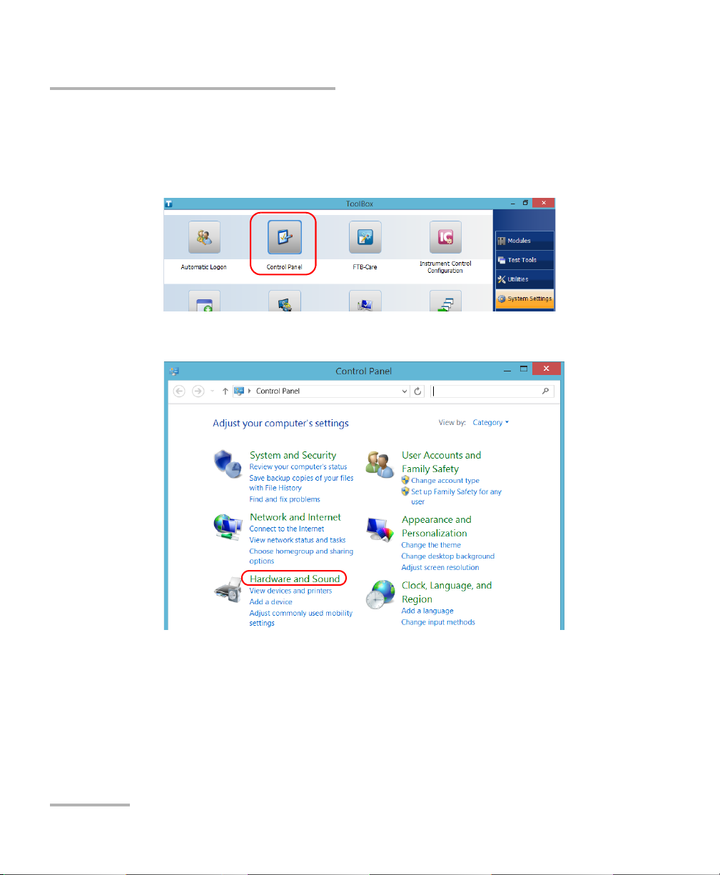
To define the behavior of the power button:
1. From the main window, tap the System Settings button.
2. Ta p Control Panel.
3. Ta p Hardware and Sound.
34 FTB-500
Page 43

Getting Started with Your Unit
Turning Off Your Unit
4. Under Power Options, tap Change what the power buttons do.
5. Ta p Changes settings that are currently unavailable.
FTB-500 35
Page 44

Getting Started with Your Unit
Turning Off Your Unit
6. From the When I press the power button lists, select the desired
behavior when the unit is powered by batteries, or by AC current (Shut
down option is selected by default in both cases).
7. Ta p Save changes to confirm the changes and return to the Power
Options window.
36 FTB-500
Page 45

Getting Started with Your Unit
Turning Off Your Unit
To configure your unit to automatically restart after AC power
comes back:
1. From the main window, tap the System Settings button.
2. Ta p Too l B ox Set u p .
3. Select the Power on the unit when AC outlet is connected or after
power outage box to enable the corresponding option.
OR
Clear the box if you prefer that your unit does not restart automatically
after AC power comes back.
4. Ta p OK to confirm the changes and return to the System Settings
window.
FTB-500 37
Page 46

Getting Started with Your Unit
Configuring Your Unit At First Startup
Configuring Your Unit At First Startup
The first time you turn on the unit, a Windows configuration wizard is
displayed, enabling you to set all the regional and language settings such as
the country and operation language.
The operation language that you select at the first startup (labelled
“App language”) becomes the default system language, that is the
language that will be available at logon.
During the configuration process, you will also be asked to read and accept
the Microsoft end-user license agreement (EULA).
Once the configuration is complete in Windows, an EXFO wizard will be
displayed, allowing you to read the user documentation for important
safety information, and to read and accept the EULA related to your unit
and instruments.
IMPORTANT
Note: To be able to work with the unit, you must accept all the EULA (from
Microsoft and EXFO), and confirm that you have read the security
information.
To configure your unit at first startup:
1. If it is not already done, turn on the unit (see Turning Off Your Unit on
page 32).
2. When the Windows wizard is displayed, set the parameters according
to your needs.
3. Read and accept the Microsoft EULA.
The configuration of Windows parameters may take several minutes.
38 FTB-500
Page 47

Getting Started with Your Unit
Configuring Your Unit At First Startup
4. When the EXFO wizard is displayed, follow the on-screen instructions.
5. Ta p Finish to close the wizard and start working.
FTB-500 39
Page 48

Getting Started with Your Unit
Accessing and Exiting ToolBox
Accessing and Exiting ToolBox
By default, ToolBox is displayed automatically when you turn on the unit.
However, you can configure your unit to send ToolBox to the notification
area (see Setting ToolBox Behavior on page 107). This could be useful, for
example, if you prefer to start working in Windows. You can also configure
your unit to start any of the available applications as soon as ToolBox is
started (see Selecting the Startup Applications on page 81).
To a cc e ss Too l Bo x f r om the Windows environment:
Tap the icon on your desktop.
Note: If ToolBox has been sent to the notification area, from this location,
right-click the icon, and then select Restore ToolBox.
To e xi t Too lB o x:
Tap .
40 FTB-500
Page 49

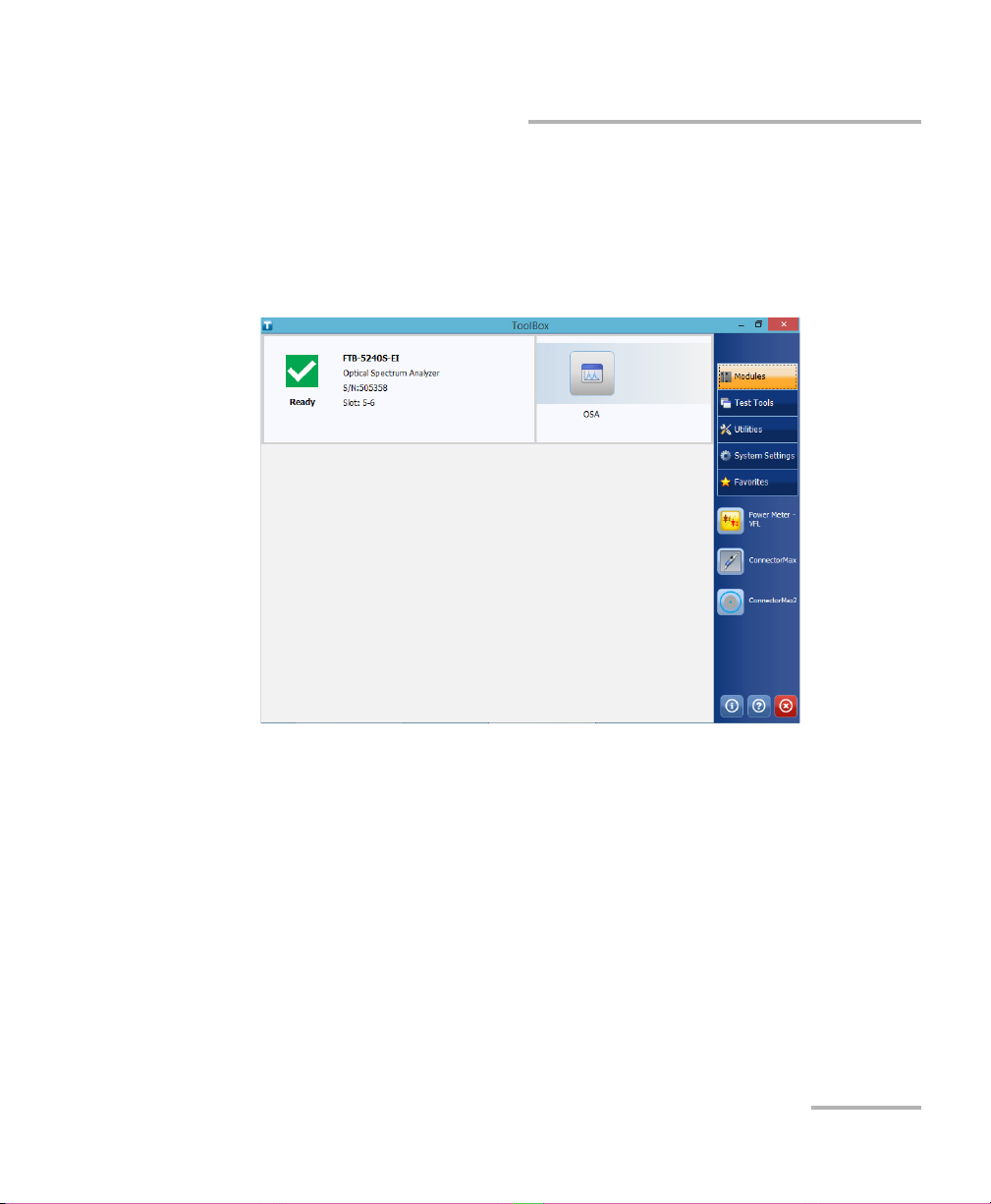
Getting Started with Your Unit
Inserted module
Applications specific to the
module
Starting Module Applications
Starting Module Applications
Your modules can be configured and controlled from their dedicated
applications in Toolbox.
To start a module application:
1. If necessary, tap the Modules button to display the modules window.
Note: The slot numbers are 0-3 for the four-slot model and 0-7 for the eight-slot
model. The slots are identified on both sides of the unit.
2. On the row corresponding to the desired module, tap the icon of the
application with which you want to work.
FTB-500 41
Page 50

Getting Started with Your Unit
Using the On-Screen (Virtual) Keyboard
Using the On-Screen (Virtual) Keyboard
Whenever you need to enter alphanumeric data, you can use the
on-screen keyboard. This keyboard supports multilingual features, and
functions according to the keyboard settings set in Windows.
To use the on-screen keyboard:
1. Select the location where you want to enter text.
2. From the taskbar, tap the on-screen keyboard icon (located to the left
of the clock).
3. Enter the data as required.
4. Close the keyboard when you are done entering data.
Working with Windows 8.1 Pro
If you are not familiar with Windows 8.1 Pro, you may want to visit
Microsoft Web site for tutorials as well as detailed information on the
features and concepts brought by this operating system.
One of the new features is the use of touchscreen gestures to perform
certain tasks. In this documentation, all the necessary gestures are
explained throughout the procedures.
Note: For an optimal accuracy with the touchscreen, use the stylus provided with
your unit.
Note: To show the taskbar, press the button from the front panel of the unit.
42 FTB-500
Page 51

Getting Started with Your Unit
Working with Windows 8.1 Pro
Here is an overview of the gestures that you may use the most with your
unit.
Tap and double-tap: Equivalent of a click and double-click with a
mouse.
Swipe right: To return to the last used application.
From the left edge of the screen, swipe towards the right.
Swipe left: To display the Charm bar, which is a special toolbar that
gives you access to many tools and settings.
From the right edge of the screen, swipe towards the left.
FTB-500 43
Page 52

Getting Started with Your Unit
Right-Clicking with the Touchscreen
Right-Clicking with the Touchscreen
If you are used to work with a mouse, you may find it useful to be able to
perform a right-click on your touchscreen.
This feature is enabled by default, but you can disable it if you prefer. You
can also modify the right-click behavior. For more information,
see Customizing the Right-Click Feature on page 73.
To right-click with the touchscreen:
From the location where you want to right-click, using the stylus or any
blunt pointing device, press the screen for a few seconds until the shortcut
menu appears.
If you want to hide the shortcut menu without performing any action,
simply tap anywhere outside the menu.
44 FTB-500
Page 53

Getting Started with Your Unit
Installing or Upgrading the Applications
Installing or Upgrading the Applications
All the necessary applications have been preinstalled and configured at the
factory. However, you may have to upgrade some applications when new
versions become available or to reinstall them.
Note: Only administrator-level users can install software under Windows.
Each time you purchase a new module, it could be a good idea to verify
that the most recent Update Manager application is installed on your unit.
When updates are available for an application, you will need to download
them from Internet, either directly on your unit or on a computer. The
update files must be copied to the location that has been specified for the
deployment packages in Update Manager.
For the installation or upgrade, you will need:
your unit
a computer equipped with a USB port; Windows must be installed on
the computer
a USB memory key
Note: The computer and USB key are only necessary if you do not wish to
download the files directly on your unit.
Note: For more information on the installation, refer to the Update Manager
online help.
FTB-500 45
Page 54

Getting Started with Your Unit
Installing or Upgrading the Applications
To update or reinstall Update Manager:
1. If necessary, retrieve the desired installation files from the Internet.
If you do not intend to download files directly on your unit, connect a
USB memory key to one of the USB ports of the computer and copy the
installation files to this USB key.
2. If it is not already done, turn on your unit.
3. Exit Toolbox and the modules’ applications.
4. If you want to install Update Manager using the USB key, disconnect it
from the computer and connect it to one of the USB ports of your unit.
5. On your unit, create a folder on the Windows desktop.
6. Copy the installation files (from the USB key) to the newly created
folder.
7. From the newly created folder, tap the Setup.exe file to start the
installation.
8. Follow the on-screen instructions.
9. When the installation is complete, simply disconnect the USB memory
key.
46 FTB-500
Page 55

Getting Started with Your Unit
Installing or Upgrading the Applications
To install or upgrade the applications:
1. If necessary, retrieve the desired installation files from the Internet.
If you do not intend to download files directly on your unit, connect a
USB memory key to one of the USB ports of the computer and copy the
installation files to this USB key.
2. If it is not already done, turn on your unit.
3. Exit Toolbox and the modules’ applications.
4. If you want to install or update applications using the USB key,
disconnect it from the computer and connect it to one of the USB ports
of your unit.
5. Copy the installation files (from the USB key) to the folder containing
the update and installation packages on your unit. By default, Update
Manager will search for files in the default folder, which is
C:\Users\Public\Documents\SoftwareUpdate. For more information,
refer to the Update Manager online help.
6. On your unit, from Windows desktop, tap the Update Manager icon to
start the corresponding application. For more information on how to
install or upgrade applications, refer to the Update Manager online
help.
7. When the installation is complete, simply disconnect the USB memory
key.
FTB-500 47
Page 56

Getting Started with Your Unit
Installing EXFO LabVIEW Drivers
Installing EXFO LabVIEW Drivers
Before being able to work with EXFO LabVIEW drivers, you must install the
following elements on your computer or on your FTB-500:
National Instruments LabVIEW software and the corresponding
patches.
EXFO LabVIEW drivers (including demo applications to help you get
started with the drivers).
You can find the LabVIEW drivers on the DVD that came with your unit, on
the EXFO Web site at www.exfo.com, or on the National Instrument Web
Site at www.ni.com.
For more information, see Working with EXFO LabVIEW Drivers on
page 244.
Note: Only administrator-level users can install software under Windows.
Note: You cannot install LabVIEW software or drivers on your unit directly from a
CD. You must use a computer to transfer the required files to a USB key first.
To install the LabVIEW software:
1. If you intend to install the LabVIEW software on your unit, transfer the
required files from the LabVIEW CD to a USB key using a computer. If
the CD also contains patches, retrieve them on the USB key as well.
2. From your computer, insert the LabVIEW CD in the CD-ROM drive.
OR
From your unit, connect the USB key containing the required files.
48 FTB-500
Page 57

Getting Started with Your Unit
Installing EXFO LabVIEW Drivers
3. If necessary, start the installation process manually as follows:
3a. Open the File Explorer ( icon in the taskbar under Windows
8.1 Pro).
Note: To access the File Explorer on your unit, from the front panel, press the
button to show the taskbar. From the lower left corner of the screen, tap the
Start button ( ),and then tap the File Explorer tile.
3b. Locate the autorun.exe file, then double-click on it to start the
installation procedure and follow the on-screen instructions.
You should keep the default names and paths suggested by the
installation program.
4. Once the software installation is complete, install the patches available
for your LabVIEW version.
If the patches are not included on your LabVIEW CD (or USB key), you
may download them from National Instruments’ Web site at
www.ni.com.
4a. Open the File Explorer ( icon in the taskbar under Windows
8.1 Pro).
Note: To access the File Explorer on your unit, from the front panel, press the
button to show the taskbar. From the lower left corner of the screen, tap the
Start button ( ),and then tap the File Explorer tile.
4b. Locate the Updates\setup.exe file, then double-click on it to start
the installation procedure, and follow the on-screen instructions.
FTB-500 49
Page 58

Getting Started with Your Unit
Installing EXFO LabVIEW Drivers
To install the EXFO LabVIEW drivers:
1. If you intend to install the LabVIEW drivers on your unit, you can either
transfer the required files from the installation CD to a USB key using a
computer or download them from the National Instruments’ Web site.
2. From your computer, insert the installation CD in the CD-ROM drive if
needed, unless you have downloaded the drivers from the National
Instruments Web site.
OR
From your unit, connect the USB key containing the required files.
3. Start the installation process as follows:
3a. Open the File Explorer ( icon in the taskbar under Windows
8.1 Pro).
Note: To access the File Explorer on your unit, from the front panel, press the
button to show the taskbar. From the lower left corner of the screen, tap the
Start button ( ),and then tap the File Explorer tile.
3b. Locate the Labview Drivers\setup.exe file, then double-click on it
to start the installation procedure and follow the on-screen
instructions.
For easier use, the drivers will be installed in LabVIEW’s default
instrument library folder:
C:\Program Files\National Instruments\LabVIEW 2012\instr.lib.
50 FTB-500
Page 59

Getting Started with Your Unit
Activating Software Options
Activating Software Options
The software options purchased at the same time as your unit have been
activated for you already. However, if you purchase options afterwards, you
will have to activate them yourself.
IMPORTANT
If you want to activate software options for modules of the
FTB-81xx Series or the FTB-85xx Series, refer to the user guide of
your product for the specific activation instructions.
In all other cases, you can follow the instructions presented in this
section.
Before being able to activate options, you need to contact EXFO with the
following information:
Purchase order number of the newly purchased options
Module or platform serial number (depending on whether the sof tware
options were purchased for a module or the platform)
Customer's name
Customer’s company name
Customer’s phone number
Customer’s e-mail address
Module or platform on which the option will be installed
You will receive a single key (.key) file with which you will be able to
unlock all the new options that you have purchased.
FTB-500 51
Page 60

Getting Started with Your Unit
Activating Software Options
To activate the options for your unit:
1. Connect a USB memory key to one of the USB ports of your computer.
2. Copy the key file to the USB memory key.
3. Disconnect the USB key from the computer and connect it to your unit.
4. From the main window, tap the System Settings button, and then tap
Options Activation.
5. When the application prompts you to authorize the changes to your
unit (identified as “computer”), tap Ye s.
52 FTB-500
Page 61

Getting Started with Your Unit
Activating Software Options
6. In the Platform Options tab, use the Browse button to locate the key
file that you want to use.
7. Ta p Activate.
The option indicator will turn into a green check mark to confirm that
the option is now active.
8. Ta p OK to close the confirmation message, and then Close to exit.
Note: At this point, if you have used a USB key to copy your key file, you can
remove it as it is not required to use your new options.
FTB-500 53
Page 62

Getting Started with Your Unit
Activating Software Options
To activate software options for your module:
1. Connect a USB memory key to one of the USB ports of your computer.
2. Copy the key file to the USB memory key.
3. Disconnect the USB key from the computer and connect it to your unit.
4. From the main window, tap the System Settings button, and then tap
Options Activation.
5. When the application prompts you to authorize the changes to your
unit (identified as “computer”), tap Ye s.
54 FTB-500
Page 63

Getting Started with Your Unit
Activating Software Options
6. In the Module Options tab, use the Browse button to locate the key
file that you want to use.
7. Ta p Activate.
The option indicator will turn into a green check mark to confirm that
the option is now active.
Note: You can see the supported options for the module in the Options list.
8. Ta p OK to close the confirmation message, and then Close to exit.
Note: At this point, if you have used a USB key to copy your key file, you can
remove it as it is not required to use your new options.
FTB-500 55
Page 64

Getting Started with Your Unit
Installing Third-Party Software on Your Unit
Installing Third-Party Software on Your Unit
Since your unit is equipped as a conventional computer would be, you can
install third-party software on it, as long as it is compatible with Microsoft
Windows 8.1 Pro.
EXFO does not provide any support for the installation, use or
troubleshooting of third-party software. Should you need help,
refer to the corresponding third-party software documentation or
technical support.
Protecting your Unit with an Antivirus Software
By default, your unit is protected with the Windows Defender antivirus
software. However, you can apply your own security standards and
antivirus strategy.
IMPORTANT
56 FTB-500
Page 65

Getting Started with Your Unit
Four-slot model Eight-slot model
Securing your Unit Using the Kensington Lock
Securing your Unit Using the Kensington Lock
Your unit is equipped with a security slot to which you can connect an
optional Kensington lock (security cable) to help prevent theft.
To secure your unit:
Connect your lock to the security slot located at the back of your unit.
FTB-500 57
Page 66

Getting Started with Your Unit
Using a Keyboard, Mouse or Other USB Devices
Using a Keyboard, Mouse or Other USB Devices
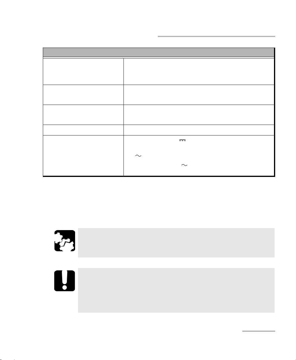
Your unit supports many USB devices. The table below gives an overview
of the supported USB devices.
Device Details
Memory key For data transfer between your unit and a computer
when you do not have access to a network. If you
need information on how to transfer data using a
memory key, see Managing Data on page 141.
Keyboard When you are required to enter alphanumeric data,
an on-screen (virtual) keyboard is displayed. However,
if you prefer, you can use a hardware keyboard.
Mouse If your prefer to use a mouse instead of the
touchscreen, you can connect one.
Composite device You can use composite devices, that is devices that
input information to your unit using more than one
mean (for example, combinations of keyboard and
mouse).
Hub This device will be particularly useful to you if you
need extra USB ports.
Printer To print documents such as reports directly from you
unit. If you prefer to use a network printer, you can
also configure one. For more information,
see Configuring Network Printers on page 83.
58 FTB-500
Page 67

Getting Started with Your Unit
Using a Keyboard, Mouse or Other USB Devices
Device Details
3G USB modem
key (purchased
from EXFO)
To access the Internet without having to connect to a
Wi-Fi or an Ethernet network. For more information,
see Accessing the Internet with a 3G USB Modem Key
on page 118.
USB to RS-232
adapter
(purchased from
EXFO)
GPS USB key
(purchased from
EXFO)
To be able to transfer data between your unit and a
device only equipped with RS-232 (serial) ports. For
more information, see Using the USB to RS-232
Adapter on page 152.
To be able to know the position of your unit (latitude
and longitude coordinates). For more information,
see Retrieving the GPS Location of Your Unit on
page 122.
You can connect several devices at the same time.
To use a USB device with your unit:
Connect the USB device to any of the USB ports located on the right panel
or on the front of the unit (see Main Features on page 2).
Note: It is not necessary to turn off the unit before connecting the USB device. The
software will automatically detect its presence.
You r dev ice i s a u tom ati cally recognized and immediately usable (provided
that it uses the drivers already available on your unit).
FTB-500 59
Page 68

Getting Started with Your Unit
Configuring an External Monitor
Configuring an External Monitor
Although your unit is equipped with a touchscreen, you might want to
connect an external monitor.
You can configure the external monitor in the Windows Control Panel. In
Control Panel, when you select the duplicate displays feature, the
resolution of the external monitor is set to 800 x 600 automatically, which
corresponds to the default resolution of the touchscreen.
Although the maximum resolution of the touchscreen is 800 x 600, you can
select a higher resolution for the external monitor with the extend displays
feature. The smallest resolution that you will then be able to select for the
external monitor is 1024 x 768.
To configure an external monitor:
1. Connect the external monitor to the Video Out port, located on the left
side of the unit.
2. From the main window, tap the System Settings button.
60 FTB-500
Page 69

3. Ta p Control Panel.
4. Ta p Hardware and Sound.
Getting Started with Your Unit
Configuring an External Monitor
FTB-500 61
Page 70

Getting Started with Your Unit
Configuring an External Monitor
5. Under Display, tap Adjust screen resolution.
6. Set the parameters according to your needs, and then tap OK to
confirm.
62 FTB-500
Page 71

4 Setting Up Your FTB-500
Adjusting Brightness
You may want to adjust the screen brightness yourself to better fit your
work environment or preferences. Values are kept in memory even when
you turn the unit off.
If you want to set the delay after which the display is turned off to save
power, see Configuring the Power Management Options on page 97.
To adjust the display brightness:
From the unit’s front panel, press the button repeatedly to switch
between the available levels.
OR
1. From the right side of the screen, swipe left to display the Charm bar.
2. Ta p Settings, and then the icon.
3. Move the slider until the screen appearance is to your liking.
The new brightness value is taken into account immediately.
FTB-500 63
Page 72

Setting Up Your FTB-500
Audio in port
(for 3.5 mm connector)
Adjusting Microphone and Speaker Volume
Adjusting Microphone and Speaker Volume
Your unit is equipped with a built-in speaker, but you can connect an
external speaker if you prefer. You can also connect a microphone or a
headset to your unit.
To fit your work environment, you may adjust the microphone as well as
the speaker (built-in or external) or headphones volume. Values are kept in
memory even when you turn the unit off.
Note: When you use a headset, ensure that both the microphone and
headphones jacks are connected properly to the appropriate audio ports.
The control of the volume for the microphone and the headphones of the
headset are independent of each other.
To adjust microphone volume:
1. Ensure that your microphone (or microphone jack if you are using a
headset) is connected to the audio in port located on the right panel of
the unit.
2. From the main window, tap the System Settings button.
64 FTB-500
Page 73

3. Ta p Control Panel.
4. Ta p Hardware and Sound.
Setting Up Your FTB-500
Adjusting Microphone and Speaker Volume
FTB-500 65
Page 74

Setting Up Your FTB-500
Adjusting Microphone and Speaker Volume
5. Under Sound, tap Manage audio devices.
6. Select the Recording tab.
7. Ensure that your microphone is selected, and then tap Properties.
66 FTB-500
Page 75

Setting Up Your FTB-500
Adjusting Microphone and Speaker Volume
8. If you are using a headset and want to hear your voice through the
headphones when you speak in the microphone, from the Listen tab,
select the Listen to this device check box.
9. From the Levels tab, move the sliders until the settings are to your
liking. If the sound coming from your microphone is too low, you may
want to adjust the boost level as well.
10. Tap OK to confirm your new settings and close the window.
11. Tap OK to close the window and return to Control Panel.
FTB-500 67
Page 76

Setting Up Your FTB-500
Audio out port
(for 3.5 mm connector)
Adjusting Microphone and Speaker Volume
To adjust speaker (or headphones) volume:
1. If necessary, ensure that the external speaker (or headphone jack if
you are using a headset) is connected to the audio out port located on
the right panel of the unit.
2. From the right side of the screen, swipe left to display the Charm bar.
3. Ta p Settings, and then the icon.
4. Move the slider until the sound level is to your liking.
Note: You can also access the sound level slider by tapping the icon from the
taskbar.
The new value is taken into account immediately.
68 FTB-500
Page 77

Setting Up Your FTB-500
Recalibrating the Touchscreen
Recalibrating the Touchscreen
If you notice the touchscreen does not behave in the way it used to
(for example, it is now difficult to select items) it probably needs a
recalibration. You can perform a 4-point, 9-point (linearization), 16-point
(linearization), or even a 25-point (linearization) calibration. You can
perform a 25-point linearization when you need more accuracy on screen
edges and corners.
You can stop the calibration process at any time, but the touchscreen will
still need calibration. The parameters are taken into account only when the
process is complete.
Note: If you have trouble accessing the touchscreen calibration feature because
the touchscreen is not behaving as expected, you can connect a USB
mouse.
IMPORTANT
To get the optimum performance out of your touchscreen:
Always use the calibration tool provided with ToolBox (not the
tool provided with Windows).
Be as accurate as possible when you press the center of the
targets that appear during touchscreen calibration. This will
ensure a greater accuracy of the touchscreen, especially along
the edges and in corners.
Do not change the default resolution of the touchscreen
(800 x 600). Doing so will affect its performance and accuracy.
FTB-500 69
Page 78

Setting Up Your FTB-500
Recalibrating the Touchscreen
To recalibrate the touchscreen:
1. From the main window, tap the System Settings button.
2. Ta p Touch Screen Calibration.
70 FTB-500
Page 79

Setting Up Your FTB-500
Select if you do not want the
calibration parameters to be
kept in memory
Recalibrating the Touchscreen
3. From the Device tab, select PenMount 6000 USB, and then tap
Configure.
4. For a 4-point calibration, tap the Standard Calibration button.
OR
For a linearization, select the number of points, and then tap Advanced
Calibration.
Note: For the advanced calibration, if you wish to view a grid showing the
FTB-500 71
difference in linearity before and after the operation, select the
Plot calibration data check box. The previous values are represented with
navy blue lines and the new ones with black lines.
Page 80

Setting Up Your FTB-500
Operation is underway
New parameters taken into account
Recalibrating the Touchscreen
5. Using the stylus (or any blunt pointing device), simply press the center
of the different targets that appear on the screen. Keep pressing until
the application displays Lift off to proceed to indicate that the new
parameters have been taken into account.
Note: If you want to stop the calibration process, stop pressing the screen. The
application will close automatically after a few seconds and you will return
to the touchscreen calibration tool window.
When the number of calibration points is reached, the application will
display a message indicating that the calibration is in progress.
6. When the application prompts you, press the center of a last target to
complete the calibration operation. Once it is done, you return to the
touchscreen calibration tool window automatically.
7. Ta p OK to close the window. Tap OK again to return to the System
Settings window.
72 FTB-500
Page 81

Setting Up Your FTB-500
Customizing the Right-Click Feature
Customizing the Right-Click Feature
By default, you can perform a “press and hold” action which corresponds
to right-clicking with your touchscreen (see Right-Clicking with the
Touchscreen on page 44). However, you can disable this feature if you
prefer.
You can also modify the delay before the unit considers that you are
right-clicking, as well as the amount of time before displaying the shortcut
menu once you have right-clicked.
To customize the right-click feature:
1. From the main window, tap the System Settings button.
2. Ta p Control Panel.
FTB-500 73
Page 82

Setting Up Your FTB-500
Customizing the Right-Click Feature
3. Ta p Hardware and Sound.
4. Ta p Pen and Touch.
74 FTB-500
Page 83

Setting Up Your FTB-500
Customizing the Right-Click Feature
5. From the list, select Press and hold.
6. Ta p Settings.
7. If you want to use the right-click feature with your unit, select the
Enable press and hold for right-clicking check box. Clear the check
box if you prefer not to use this feature.
FTB-500 75
Page 84

Setting Up Your FTB-500
Customizing the Right-Click Feature
8. If you want to modify the response time of the right-click, move the
Speed or Duration sliders to adjust the configuration to your needs.
9. Ta p OK to confirm your changes.
76 FTB-500
Page 85

Setting Up Your FTB-500
Enabling or Disabling the Automatic Logon
Enabling or Disabling the Automatic Logon
Note: Only administrator-level users can enable or disable the automatic logon
feature.
You can configure your unit to automatically log on to Windows at startup
(no need to select a user and enter a password). You can also disable this
feature if you prefer to define separate user accounts with different user
access rights and passwords.
Note: For security reasons, when the unit comes back from sleep mode, the
application will prompt you to select a user and enter a password (if you
have defined one), even if you have enabled the automatic logon feature.
Also for security reasons, by default, the automatic logon is not enabled.
Once it is enabled, if you want to modify the password of the user account
for which the automatic logon is enabled, you will have to disable the
feature first, and then enable it again once the new password is defined.
If you want to modify the account used for the automatic logon, you will
also have to disable the feature first, and then enable it again for the new
account.
IMPORTANT
The user name and password that you specify for the automatic
logon must correspond to those of an existing user account.
You can create user accounts or modify passwords from the
Accounts window (Charm bar > Settings > Change PC settings >
Accounts).
FTB-500 77
Page 86

Setting Up Your FTB-500
Enabling or Disabling the Automatic Logon
To enable the automatic logon:
1. From the main window, tap the System Settings button.
2. Ta p Automatic Logon.
3. From the User Accounts window, clear the Users must enter a user
name and password to use this computer check box.
4. Ta p OK to confirm.
78 FTB-500
Page 87

Setting Up Your FTB-500
Enabling or Disabling the Automatic Logon
5. Enter the desired user name (account) and the corresponding
password.
6. Ta p OK to confirm and to return the System Settings window.
At next startup, you will no longer need to specify a user name and
password (except if the unit comes back from sleep mode).
To disable the automatic logon:
1. From the main window, tap the System Settings button.
2. Ta p Automatic Logon.
FTB-500 79
Page 88
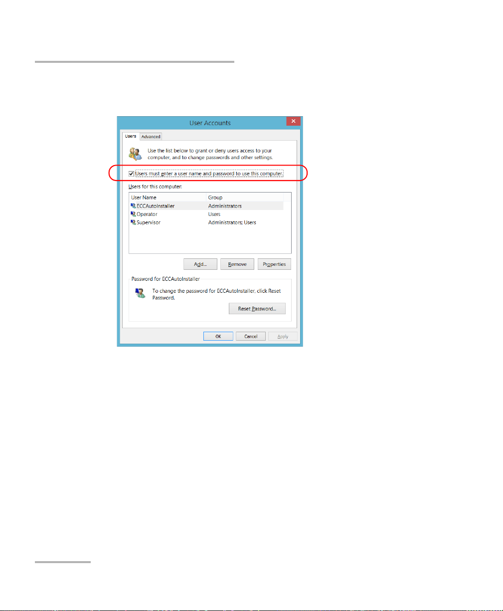
Setting Up Your FTB-500
Enabling or Disabling the Automatic Logon
3. From the User Accounts window, select the Users must enter a user
name and password to use this computer check box.
4. Ta p OK to confirm and to return the System Settings window.
At next startup, you will have to specify the user name and password.
80 FTB-500
Page 89

Setting Up Your FTB-500
Selecting the Startup Applications
Selecting the Startup Applications
The first time you start your unit, Toolbox is displayed. You can configure
your unit to automatically start any of the available applications as soon as
Toolbox is started. This can save you time, as you do not need to ensure
that they are already running before starting your tests.
If the required module is not present in the unit, the specified applications
will simply not be started. In some cases, you may have to select the
applications again the next time the module is inserted into the unit.
To set applications to start automatically at Toolbox startup:
1. From the main window, tap the System Settings button.
2. Ta p Startup Applications.
FTB-500 81
Page 90

Setting Up Your FTB-500
Selecting the Startup Applications
3. Under Module Applications or Other Applications, select the
applications you want to start automatically by selecting the
corresponding check boxes.
4. Ta p OK to use the new settings. Tap Cancel to exit without using the
new settings.
Note: The new settings will be taken into account the next time Toolbox is started.
82 FTB-500
Page 91

Setting Up Your FTB-500
Configuring Network Printers
Configuring Network Printers
Your unit supports both (local) USB and network printers (you may have to
install specific drivers on your unit).
For more information on USB printers connection, see Using a Keyboard,
Mouse or Other USB Devices on page 58.
To print documents and images on a network printer, you must configure
the printer first. You must know the IP address of the network printer that
you want to configure, and ensure that your unit is connected to the same
network as the printer (either wireless or Ethernet connection). Contact
your network administrator for more information on your specific network
configuration.
For more information on printing, see Printing Documents on page 113.
To configure the printer:
1. From the main window, tap the System Settings button.
2. Ta p Control Panel.
FTB-500 83
Page 92

Setting Up Your FTB-500
Configuring Network Printers
3. Under Hardware and Sound, tap View devices and printers.
4. Ta p Add a printer.
5. Follow the on-screen instructions.
84 FTB-500
Page 93

Setting Up Your FTB-500
Selecting the Language of Operation
Selecting the Language of Operation
You may display the user interface in one of the available languages.
The availability of the languages is function of the language group that was
installed on your unit at time of purchase. It is possible to download
language packs from the Microsoft Website to add extra languages if
necessary.
The ToolBox application is offered in several languages. This means that if
ToolBox supports the language currently selected in Windows, it will
automatically be displayed in this language. If the selected language is not
supported, the English version will be used.
When you change the interface language, the corresponding keyboard is
automatically added to the list of available keyboards. You can then enter
text in a specific language (both on-screen or “real” keyboards). Once the
keyboards are added, you can switch easily from one input language to
another.
Values are kept in memory even when you turn the unit off.
FTB-500 85
Page 94

Setting Up Your FTB-500
Selecting the Language of Operation
To select a new interface language:
1. From the main window, tap the System Settings button.
2. Ta p Control Panel.
3. Under Clock, Language, and Region, tap Add a language.
86 FTB-500
Page 95

Selecting the Language of Operation
4. Select the desired language from the list.
5. Ta p Options.
Setting Up Your FTB-500
FTB-500 87
Page 96

Setting Up Your FTB-500
Selecting the Language of Operation
6. If you want to select another keyboard layout than the one that has
been added by default, proceed as follows.
6a. Under Input method, tap Add an input method.
6b. Select the desired keyboard layout, and then tap Add.
88 FTB-500
Page 97

Setting Up Your FTB-500
Selecting the Language of Operation
7. Under Windows display language, tap Make this the primary
language.
8. When the application prompts you to log off, tap Log off now.
9. Once you see the lock screen, swipe it down to reveal the user
accounts.
10. Log to your user account.
The new language is now selected and you are able to switch from one
input language to another.
FTB-500 89
Page 98

Setting Up Your FTB-500
Language code
Selecting the Language of Operation
To switch from one of the available input languages to another:
1. If necessary, from the front panel of the unit, press the button to
show the taskbar.
2. From the taskbar, tap the language code to display the list of available
input languages.
3. From the list of languages, select the desired one.
You are now ready to start entering text in the selected input language.
Note: Modifying the input language does not modify the language of the
interface.
To download language packs:
1. Ensure that your unit has access to the Internet.
2. From the main window, tap the System Settings button.
90 FTB-500
Page 99

Setting Up Your FTB-500
Selecting the Language of Operation
3. Ta p Control Panel.
4. Under Clock, Language, and Region, tap Add a language.
FTB-500 91
Page 100

Setting Up Your FTB-500
Selecting the Language of Operation
5. Ta p Add a language.
6. Browse the list of languages, and then select the one that you want to
use.
7. Ta p Open to access the list of sub-languages.
92 FTB-500
 Loading...