

Page 1
FTB-3930
Multifunction Loss Tester
User Guide
Page 2

Copyright © 2004–2014 EXFO Inc. All rights reserved. No part of this
publication may be reproduced, stored in a retrieval system or transmitted
in any form, be it electronically, mechanically, or by any other means such
as photocopying, recording or otherwise, without the prior written
permission of EXFO Inc. (EXFO).
Information provided by EXFO is believed to be accurate and reliable.
However, no responsibility is assumed by EXFO for its use nor for any
infringements of patents or other rights of third parties that may result from
its use. No license is granted by implication or otherwise under any patent
rights of EXFO.
EXFO’s Commerce And Government Entities (CAGE) code under the North
Atlantic Treaty Organization (NATO) is 0L8C3.
The information contained in this publication is subject to change without
notice.
Trademarks
EXFO’s trademarks have been identified as such. However, the presence
or absence of such identification does not affect the legal status of any
trademark.
Units of Measurement
Units of measurement in this publication conform to SI standards and
practices.
Version number: 9.0.2
ii FTB-3930
Page 3

Contents
Contents
Certification Information ........................................................................................................v
1 Introducing the FTB-3930 Multifunction Loss Tester ................................. 1
Main Features .........................................................................................................................1
Typical Applications ................................................................................................................3
Conventions ............................................................................................................................4
2 Safety Information ....................................................................................... 5
Other Safety Symbols on Your Unit .........................................................................................6
Laser Safety Information (Units without VFL) ..........................................................................7
Laser Safety Information (Units with VFL) ...............................................................................7
Electrical Safety Information ...................................................................................................8
3 Customizing Your Multifunction Loss Tester .............................................. 9
4 Setting Up Your Multifunction Loss Tester ............................................... 11
Installing the EXFO Universal Interface (EUI) .........................................................................11
Cleaning and Connecting Optical Fibers ...............................................................................12
Setting Autonaming Scheme ................................................................................................14
Setting Pass/Fail Thresholds ..................................................................................................16
5 Measuring Power or Loss .......................................................................... 19
Defining the List of Favorite Wavelengths .............................................................................20
Nulling Electrical Offsets .......................................................................................................22
Referencing Your Power Meter to a Source ...........................................................................23
Measuring Power or Loss ......................................................................................................26
6 Measuring Optical Return Loss ................................................................. 29
Performing ORL Reference and Setting ORL Zero Value ........................................................30
Performing and Saving ORL Measurements ..........................................................................32
7 Performing Automated IL/ORL/Length Measurements (FasTesT) ............ 35
Setting Up the FasTest ...........................................................................................................36
Referencing Units for FasTesT ................................................................................................38
Performing the FasTesT .........................................................................................................43
8 Managing Test Results ............................................................................... 49
Viewing and Deleting Results ...............................................................................................49
Customizing Result Display ...................................................................................................52
Customizing and Printing Reports (FTB-500) ........................................................................54
9 Using a Light Source .................................................................................. 57
Multifunction Loss Tester iii
Page 4

Contents
10 Identifying Fiber Faults Visually ................................................................61
11 Communicating with Other Users .............................................................63
Sending and Receiving Text Messages ..................................................................................63
Communicating by Voice ......................................................................................................66
12 Maintenance ................................................................................................69
Cleaning EUI Connectors ......................................................................................................69
Cleaning Detector Ports ........................................................................................................72
Cleaning VFL-Type Connectors ..............................................................................................73
Recalibrating the Unit ...........................................................................................................74
Recycling and Disposal (Applies to European Union Only) ....................................................75
13 Troubleshooting ..........................................................................................77
Solving Common Problems ...................................................................................................77
Obtaining Online Help ..........................................................................................................80
Contacting the Technical Support Group ..............................................................................81
Transportation ......................................................................................................................82
14 Warranty ......................................................................................................83
General Information .............................................................................................................83
Liability .................................................................................................................................84
Exclusions .............................................................................................................................84
Certification ..........................................................................................................................84
Service and Repairs ...............................................................................................................85
EXFO Service Centers Worldwide ..........................................................................................86
A Technical Specifications ..............................................................................87
Index .................................................................................................................89
iv FTB-3930
Page 5

Certification Information
Certification Information
North America Regulatory Statement
This unit was certified by an agency approved in both Canada and the
United States of America. It has been evaluated according to applicable
North American approved standards for product safety for use in Canada
and the United States.
Electronic test and measurement equipment is exempt from FCC part 15,
subpart B compliance in the United States of America and from ICES-003
compliance in Canada. However, EXFO Inc. makes reasonable efforts to
ensure compliance to the applicable standards.
The limits set by these standards are designed to provide reasonable
protection against harmful interference when the equipment is operated in
a commercial environment. This equipment generates, uses, and can
radiate radio frequency energy and, if not installed and used in accordance
with the user guide, may cause harmful interference to radio
communications. Operation of this equipment in a residential area is likely
to cause harmful interference in which case the user will be required to
correct the interference at his own expense.
Modifications not expressly approved by the manufacturer could void the
user's authority to operate the equipment.
European Community Declaration of Conformity
An electronic version of the declaration of conformity for your product is
available on our website at www.exfo.com. Refer to the product’s page on
the Web site for details.
Multifunction Loss Tester v
Page 6

Page 7
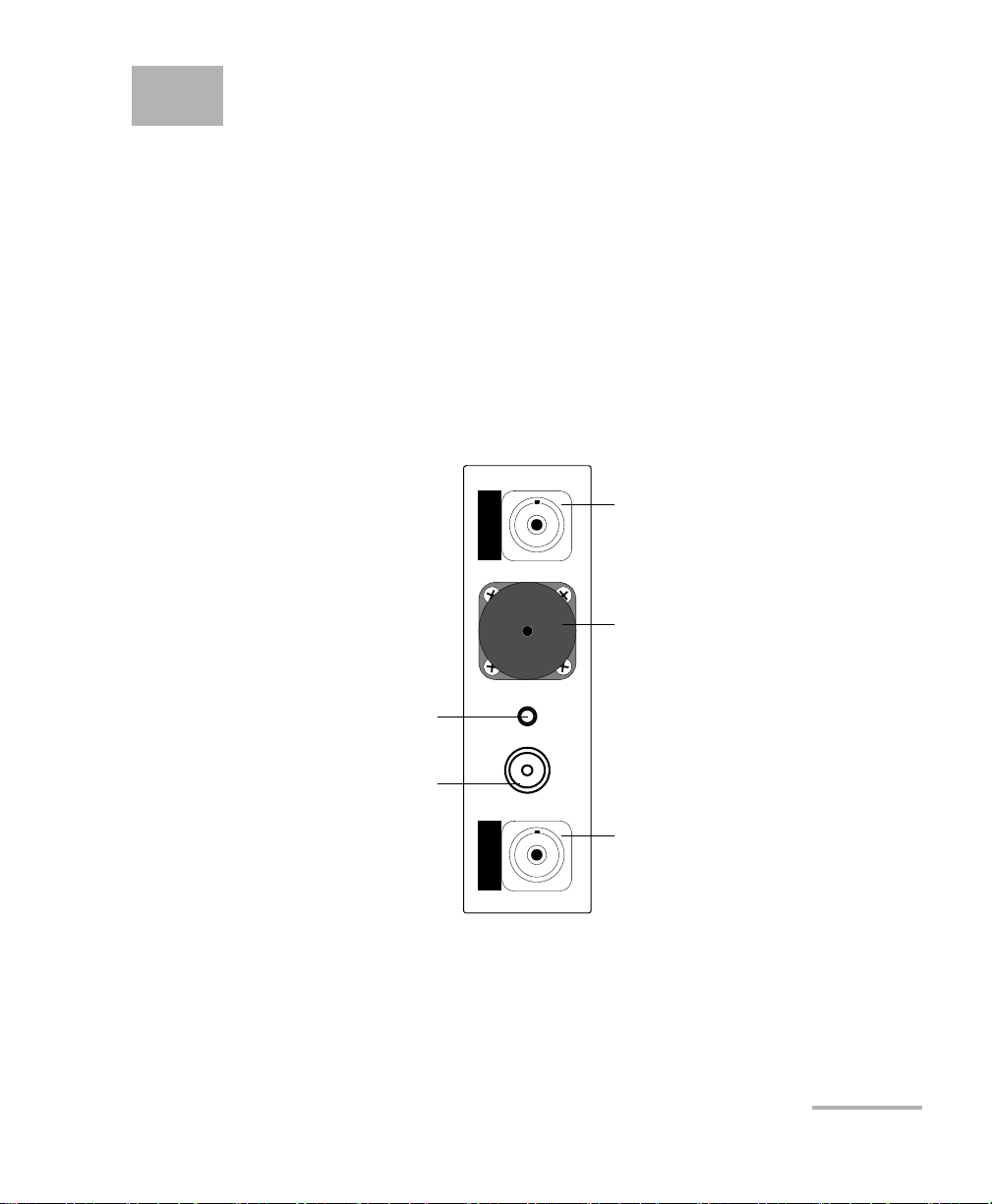
1 Introducing the FTB-3930
FTB-3930
MULTITEST
Headset connector (for any
commercially available
headset equipped with a
microphone, and having a
2.5 mm connector)
Power meter detector port
Visual fault locator port
Multimode port
(F
ASTEST and light source)
or talk set port
Singlemode port (F
ASTEST,
light source and ORL meter)
Multifunction Loss Tester
The FTB-3930 Multifunction Loss Tester integrates a power meter and light
sources with an optical return loss meter, optional talk set and visual fault
locator.
Main Features
The unit features FASTEST™, EXFO’s one-touch automated measurement.
In 10 seconds, you can simultaneously test IL and ORL at up to four
wavelengths, in both directions. During the same test, the unit also
determines fiber length.
Note: Optical ports and connectors may differ from the illustration.
Multifunction Loss Tester 1
Page 8

Introducing the FTB-3930 Multifunction Loss Tester
Main Features
The power meter has the following characteristics:
Ge, GeX or InGaAs detector with 40 calibrated wavelengths to measure
absolute power or link loss
Editable list of favorite wavelengths for easy access
Modulated signal detection
No offset nulling required in normal operation
The light source has the following characteristics:
Singlemode port (two or three wavelengths), also used for FASTEST and
ORL.
AND/OR
Multimode port (two wavelengths), also used for F
Modulated or high-power signal compatible with other EXFO units
ASTEST only.
2 FTB-3930
Page 9

Introducing the FTB-3930 Multifunction Loss Tester
Typical Applications
Other test utilities:
Text messaging
Full-duplex digital talk set (optional)
Visual fault locator to inspect or identify fibers (optional)
Result processing and analysis features (also available in the FastReporter
application):
Analyze data acquired on the field using a tabular format
Customizable test thresholds with visual pass/fail analysis
Transfer data from the FOT-930 Multifunction Loss Tester (using the
Handheld Data Transfer application) for easier management and
greater storage capacity
Save your OLTS data in popular text formats (XML, ASCII, etc.) or
convert older result files to the new format for analysis
Customize user settings and cable identification parameters
Generate and print reports about OLTS data, including user and test
location information and operator comments
FASTEST results displayed according to FTTx usage and terminology
Typical Applications
You can use the Multifunction Loss Tester for several applications, such as:
Fiber installation and maintenance applications
FTTx: testing of passive optical networks (PONs)
Absolute power or link loss measurements
Bidirectional loss and ORL testing
Length measurement
All-in-one tool for contractors
Multifunction Loss Tester 3
Page 10

Introducing the FTB-3930 Multifunction Loss Tester
Conventions
Conventions
Before using the product described in this guide, you should understand
the following conventions:
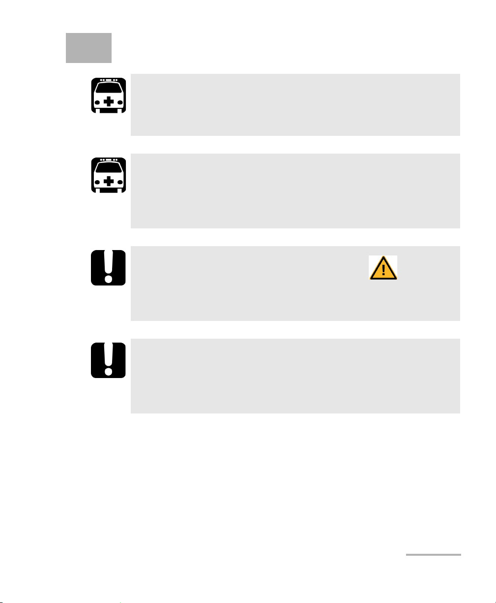
WARNING
Indicates a potentially hazardous situation which, if not avoided,
could result in death or serious injury. Do not proceed unless you
understand and meet the required conditions.
CAUTION
Indicates a potentially hazardous situation which, if not avoided,
may result in minor or moderate injury. Do not proceed unless you
understand and meet the required conditions.
CAUTION
Indicates a potentially hazardous situation which, if not avoided,
may result in component damage. Do not proceed unless you
understand and meet the required conditions.
IMPORTANT
Refers to information about this product you should not overlook.
4 FTB-3930
Page 11
2 Safety Information
WARNING
Do not install or terminate fibers while a light source is active.
Never look directly into a live fiber and ensure that your eyes are
protected at all times.
WARNING
The use of controls, adjustments and procedures, namely for
operation and maintenance, other than those specified herein may
result in hazardous radiation exposure or impair the protection
provided by this unit.
IMPORTANT
When you see the following symbol on your unit , make sure
that you refer to the instructions provided in your user
documentation. Ensure that you understand and meet the required
conditions before using your product.
IMPORTANT
Other safety instructions relevant for your product are located
throughout this documentation, depending on the action to
perform. Make sure to read them carefully when they apply to your
situation.
Multifunction Loss Tester 5
Page 12
Safety Information
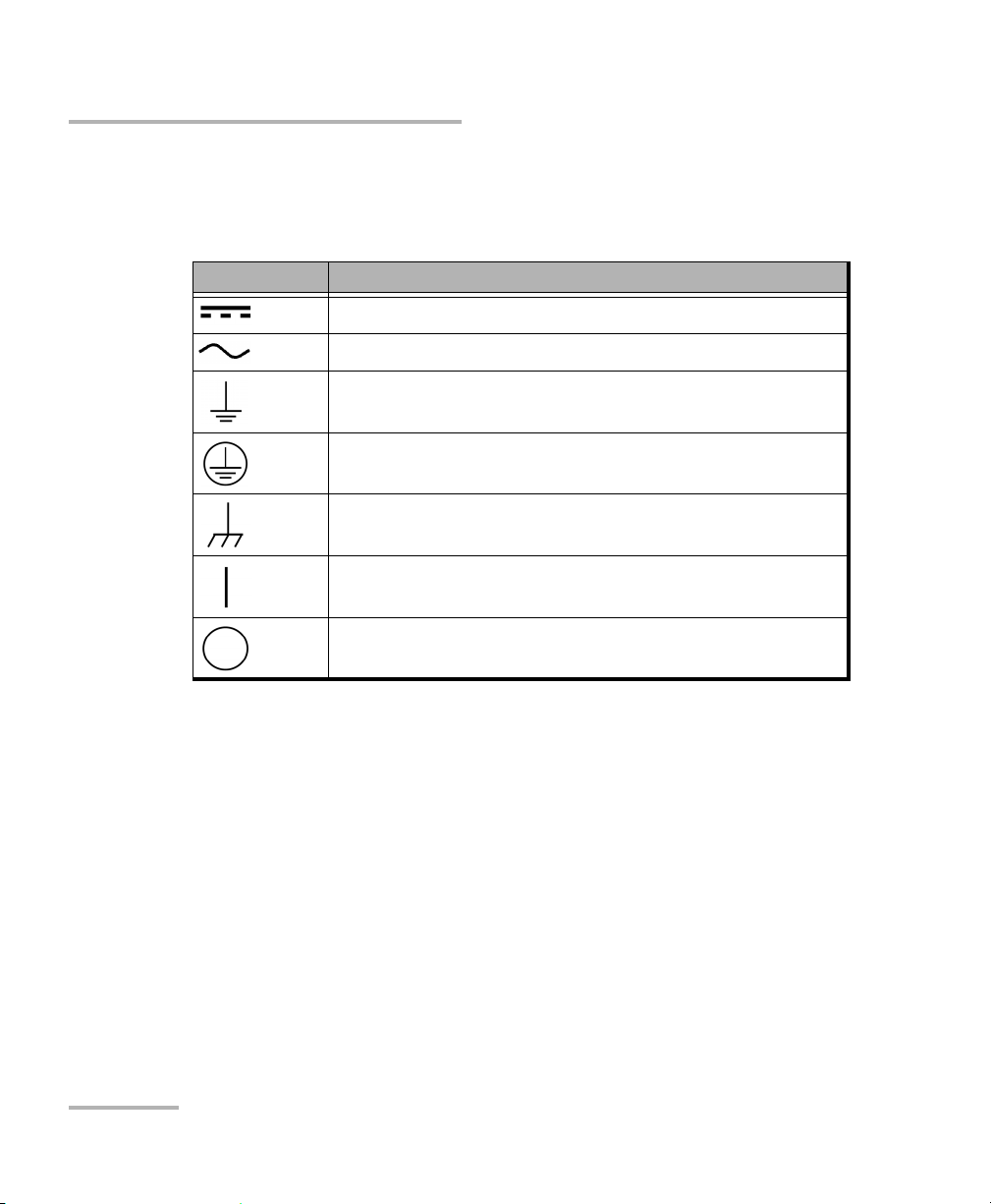
Other Safety Symbols on Your Unit
Other Safety Symbols on Your Unit
One or more of the following symbols may also appear on your unit.
Symbol Meaning
Direct current
Alternating current
The unit is equipped with an earth (ground) terminal.
The unit is equipped with a protective conductor terminal.
The unit is equipped with a frame or chassis terminal.
On (Power)
Off (Power)
6 FTB-3930
Page 13
Safety Information
Affixed to
side of module
Indicated on
front panel
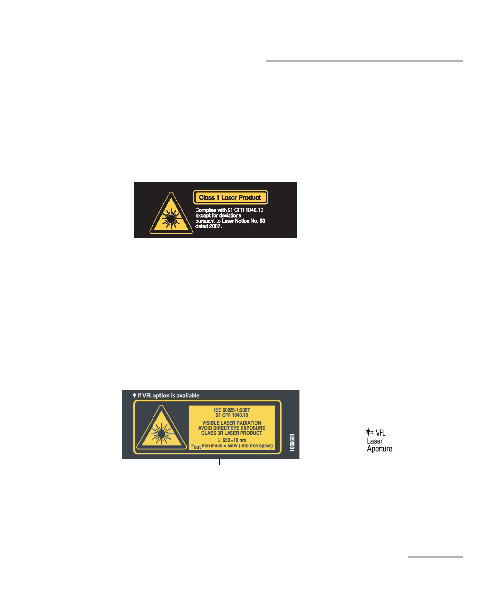
Laser Safety Information (Units without VFL)
Laser Safety Information (Units without VFL)
Your instrument is a Class 1 laser product in compliance with standards
IEC 60825-1: 2007 and 21 CFR 1040.10, except for deviations pursuant to
Laser Notice No. 50, dated June 24, 2007. Invisible laser radiation may be
encountered at the output port.
The following label indicates that a product contains a Class 1 source:
Note: The label is shown for information purposes only and are not necessarily
applied on your module.
Laser Safety Information (Units with VFL)
Your instrument is a Class 3R laser product in compliance with standards
IEC 60825-1: 2007 and 21 CFR 1040.10, except for deviations pursuant to
Laser Notice No. 50, dated June 24, 2007. Laser radiation is emitted at the
output port. It is potentially harmful in direct intrabeam viewing.
The following label(s) indicate that the product contains a Class 3R source:
The maximum input power for the FTB-3930 Multifunction Loss Tester
is 1.48 W. For more information on equipment ratings, refer to the user
documentation for your platform.
Multifunction Loss Tester 7
Page 14

Safety Information
Electrical Safety Information
Electrical Safety Information
When you use the unit outdoors, ensure that it is protected from
liquids, dust, direct sunlight, precipitation, and full wind pressure.
CAUTION
8 FTB-3930
Page 15
3 Customizing Your
Multifunction Loss Tester
Note: Your screen display may differ slightly from the figures in this user
documentation depending on the platform you are using.
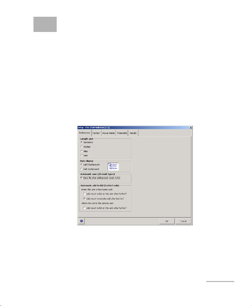
To set a length/distance unit and data display color (for the
FTB-500):
1. From the main window, press Setup, then select the Preferences tab.
2. Select the desired unit. In the case of the FTB-500 platform, you can
also select the background color.
Note: The length unit affects thresholds and fiber length only.
Multifunction Loss Tester 9
Page 16

Customizing Your Multifunction Loss Tester
To automate adding and saving results:
1. From the main window, press Setup, then select the Preferences tab.
2. Select one or more of the following options:
Save file after adding each result to list: if you select this option,
you will not need to manually save your file (with Save or Save As)
after adding your result to the Te s te d fibe r s list. The asterisk will
never appear in the title bar. In the case of the FTB-200 v2 platform,
the file is saved after adding 10 results to the list.
Add result to list on this unit after FASTEST: if you select this
option, you will not need to press Add to add your result to the
Test e d fi b ers list. When your Multifunction Loss Tester is the
remote unit, it consequently ignores automatic save settings from
the master unit.
Add result to remote unit after FASTEST: if you select this option
and your Multifunction Loss Tester is the master unit, the result will
automatically be sent and stored on the remote unit.
Note: For details about naming settings, see Setting Autonaming Scheme on
page 14.
10 FTB-3930
Page 17
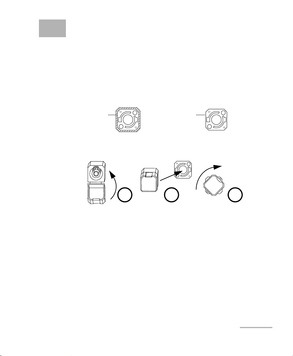
4 Setting Up Your Multifunction
Bare metal
(or blue border)
indicates UPC
option
Green border
indicates APC
option
2 3 4
Loss Tester
Installing the EXFO Universal Interface (EUI)
The EUI fixed baseplate is available for connectors with angled (APC) or
non-angled (UPC) polishing. A green border around the baseplate
indicates that it is for APC-type connectors.
To install an EUI connector adapter onto the EUI baseplate:
1. Hold the EUI connector adapter so the dust cap opens downwards.
2. Close the dust cap in order to hold the connector adapter more firmly.
3. Insert the connector adapter into the baseplate.
4. While pushing firmly, turn the connector adapter clockwise on the
baseplate to lock it in place.
Multifunction Loss Tester 11
Page 18

Setting Up Your Multifunction Loss Tester
Cleaning and Connecting Optical Fibers
Cleaning and Connecting Optical Fibers
IMPORTANT
To ensure maximum power and to avoid erroneous readings:
Always inspect fiber ends and make sure that they are clean as
explained below before inserting them into the port. EXFO is
not responsible for damage or errors caused by bad fiber
cleaning or handling.
Ensure that your patchcord has appropriate connectors. Joining
mismatched connectors will damage the ferrules.
To connect the fiber-optic cable to the port:
1. Inspect the fiber using a fiber inspection microscope. If the fiber is
clean, proceed to connecting it to the port. If the fiber is dirty, clean it as
explained below.
2. Clean the fiber ends as follows:
2a. Gently wipe the fiber end with a lint-free swab dipped in isopropyl
alcohol.
2b. Use compressed air to dry completely.
2c. Visually inspect the fiber end to ensure its cleanliness.
12 FTB-3930
Page 19

Setting Up Your Multifunction Loss Tester
Cleaning and Connecting Optical Fibers
3. Carefully align the connector and port to prevent the fiber end from
touching the outside of the port or rubbing against other surfaces.
If your connector features a key, ensure that it is fully fitted into the
port’s corresponding notch.
4. Push the connector in so that the fiber-optic cable is firmly in place,
thus ensuring adequate contact.
If your connector features a screwsleeve, tighten the connector
enough to firmly maintain the fiber in place. Do not overtighten, as this
will damage the fiber and the port.
Note: If your fiber-optic cable is not properly aligned and/or connected, you will
notice heavy loss and reflection.
EXFO uses good quality connectors in compliance with EIA-455-21A
standards.
To keep connectors clean and in good condition, EXFO strongly
recommends inspecting them with a fiber inspection probe before
connecting them. Failure to do so will result in permanent damage to the
connectors and degradation in measurements.
Multifunction Loss Tester 13
Page 20

Setting Up Your Multifunction Loss Tester
Setting Autonaming Scheme
Setting Autonaming Scheme
When starting a new file, the unit suggests an initial fiber name. After
adding a result to the Tes t ed fi be rs list, the unit prepares the next fiber
name by incrementing the suffix.
When you manually change the name for the first time (in Power Meter,
ORL Meter or F
ASTEST), the unit then ignores autonaming settings.
IMPORTANT
To start using new autonaming settings, you must close the current
file.
Cable names: maximum 60 characters for prefix, plus 3-digit suffix
(or Microsoft Windows limitations when name is manually set)
Fiber names: maximum 11 characters for prefix, plus 3-digit suffix
(duplicate names allowed when name is manually set)
Note: If you manually change a fiber name, then turn the unit off without saving
at least one result, this name will be discarded.
14 FTB-3930
Page 21

Setting Up Your Multifunction Loss Tester
Setting Autonaming Scheme
To set the autonaming scheme:
1. From the main window, press Setup, then select the Results tab.
2. Set the names/values, then press OK.
Note: The cable name you set here will be the suggested file name when saving.
Multifunction Loss Tester 15
Page 22

Setting Up Your Multifunction Loss Tester
Setting Pass/Fail Thresholds
Setting Pass/Fail Thresholds
You can define groups of thresholds to specify acceptable power (in W or
dBm), power reference (in dB), F
unit) and ORL values (in dB) for each wavelength.
Thresholds are supplied by system manufacturers and depend on the
system deployed.
Measurements exceeding a threshold are shown with an exclamation
mark. In the test tabs, these measurements also have a red background.
ASTEST loss (in dB and dB per distance
IMPORTANT
Thresholds are not saved with measurements. Results are compared
to the threshold group currently associated to the file (for F
results, not necessarily the master unit).
Note: When transferring results from handheld unit to computer, thresholds are
not transferred along with results.
ASTEST
16 FTB-3930
Page 23
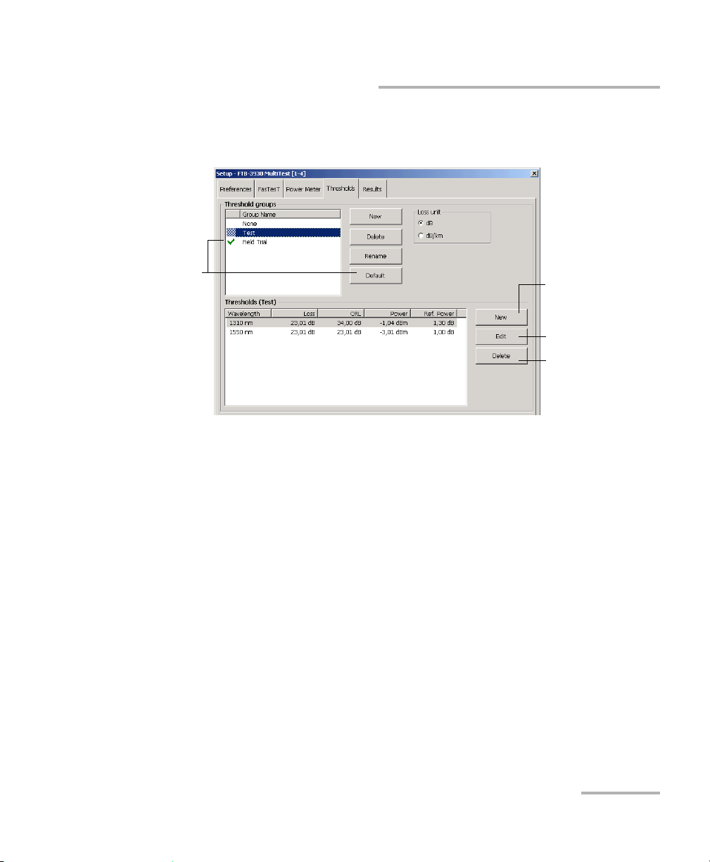
Setting Up Your Multifunction Loss Tester
Delete thresholds for
selected wavelength
Default
threshold group
(applies to FasTesT,
Power Meter and
ORL Meter tabs)
Edit thresholds for
selected wavelength
Add wavelength and
its thresholds
Setting Pass/Fail Thresholds
To set power, loss or ORL thresholds:
1. From the button bar, press Setup, then select the Thresholds tab.
2. In the Threshold groups list, select a group to modify.
OR
Create a new group by pressing New. Duplicate names are allowed,
but you should always use distinct names to avoid confusion.
3. Select loss units (dB or dB/distance; distance units are selected in the
Preferences tab). In the case of the FTB-200 v2, you can select also the
power units.
Multifunction Loss Tester 17
Page 24
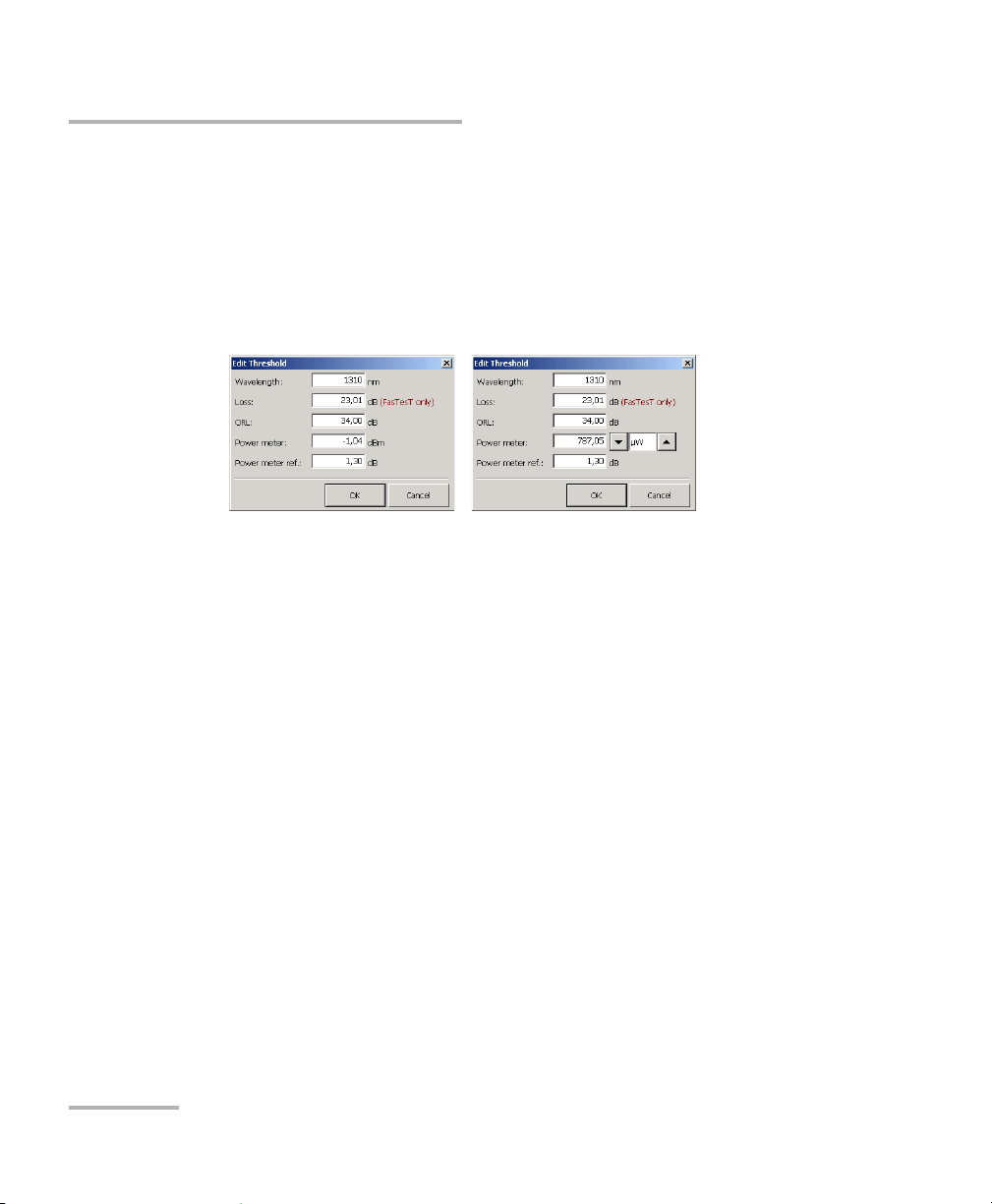
Setting Up Your Multifunction Loss Tester
dBm power units
selected in Results tab
Watt power units
selected in Results tab
Setting Pass/Fail Thresholds
4. In the Thresholds list, select a wavelength for which you want to set
thresholds, then press Edit.
OR
Add a new wavelength to the list by pressing New. Wavelengths that
are not supported by F
ASTEST are simply ignored in FASTEST result
tables.
5. In the text boxes, modify threshold values for the selected wavelength,
then press OK to confirm the new thresholds (or Cancel to return to
previous values).
You s ele ct F
ASTEST loss units (dB or dB/distance) on the Thresholds
tab (and distance units on the Preferences tab).
Note: For the FTB-500, you select power units on the Results tab.
6. Press OK to return to the main window.
To rename a threshold group:
1. From the Thresholds tab, select a group in the Threshold groups list.
2. Press Rename, then set the new name (maximum 64 characters) and
press OK.
18 FTB-3930
Page 25
5 Measuring Power or Loss
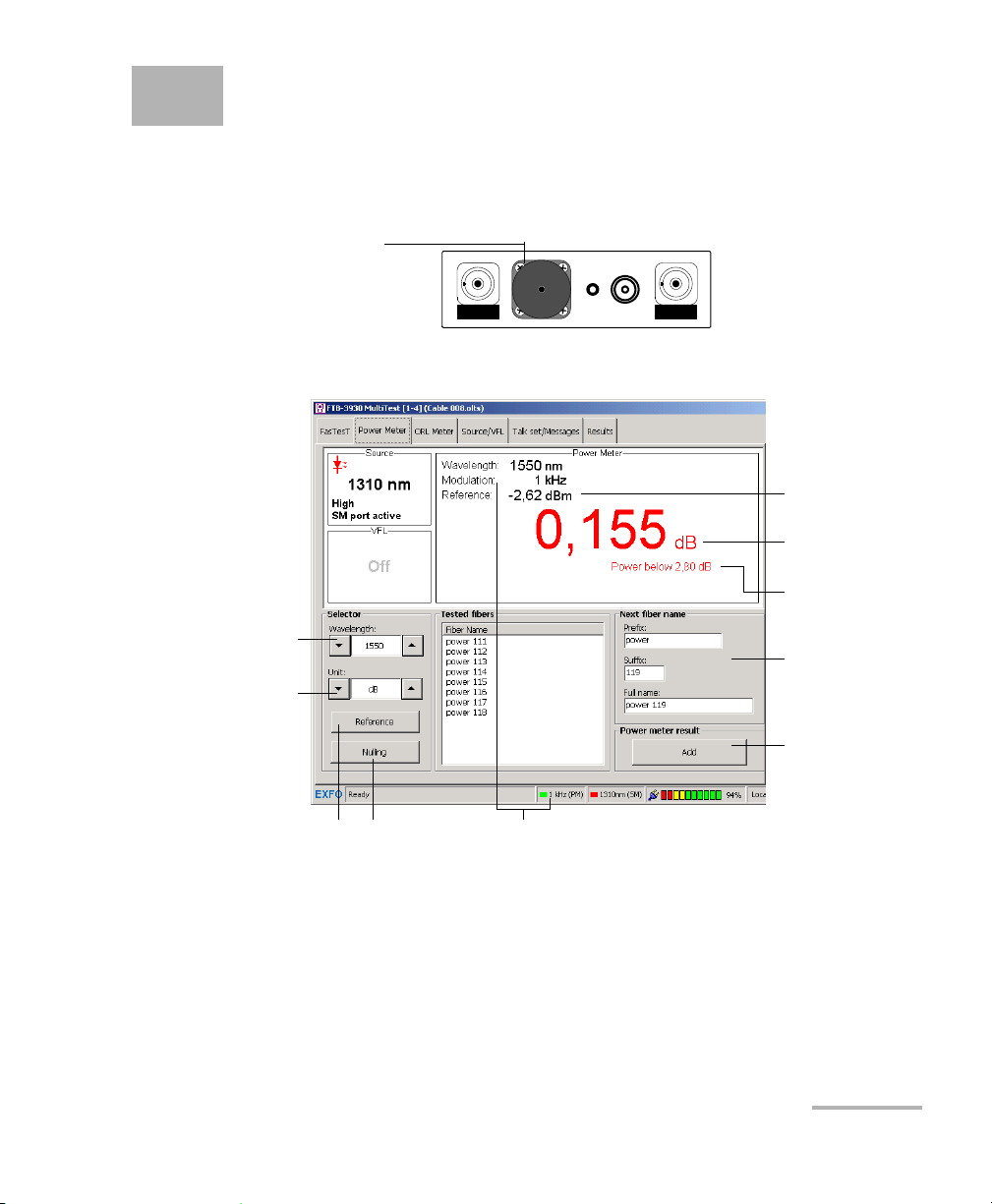
FTB-3930
MULTITEST
Power meter port
Power meter port
Measured
power/loss
Modulation
detected
Reference
power
Value under
threshold
Add current value
to Te s t ed f ib e r s
(to actually save
data, press Save
on function bar)
Perform offset
nulling
Set reference for
loss measurement
Display power
(W or dBm)
or loss (dB)
Change name of
next saved fiber
Switch between
favorite wavelengths
The FTB-3930 Multifunction Loss Tester is equipped with an optical power
meter to measure absolute power (in dBm or W) or insertion loss (in dB).
The power meter port is independent of the F
The following functions are available on your power meter:
ASTEST port.
Multifunction Loss Tester 19
Page 26

Measuring Power or Loss
Defining the List of Favorite Wavelengths
Defining the List of Favorite Wavelengths
You must put the wavelengths you want to use on a list of favorite
wavelengths. Only wavelengths selected from this list are available for
measurements.
By default, the list contains 22 of the 40 calibrated wavelengths. It can
contain a maximum of 30 wavelengths.
Specifications are guaranteed for calibrated wavelengths only. For other
wavelengths, the unit will determine values based on the calibrated
wavelengths (3-point interpolation).
Detector
Type
InGaAs
Ge
800, 820, 830, 840, 850, 860, 870,
880, 910, 980, 1270, 1280, 1290,
1300, 1310, 1320, 1330, 1340, 1390,
1450, 1460, 1470, 1480, 1490, 1500,
1510, 1520, 1530, 1540, 1550, 1560,
1570, 1580, 1590, 1600, 1610, 1620,
1630, 1640, 1650.
GeX All the above, plus 1370 and 1060. Same as above.
Calibrated
Wavelengths (nm)
Default Favorite
Wavelengths (nm)
800, 840, 850,
860, 910, 980,
1280, 1300, 1310,
1320, 1450,
1470, 1480, 1490,
1510, 1520, 1530, 1540,
1550, 1560,1570, 1625.
Note: The list must always contain at least one selected wavelength.
20 FTB-3930
Page 27
Measuring Power or Loss
Defining the List of Favorite Wavelengths
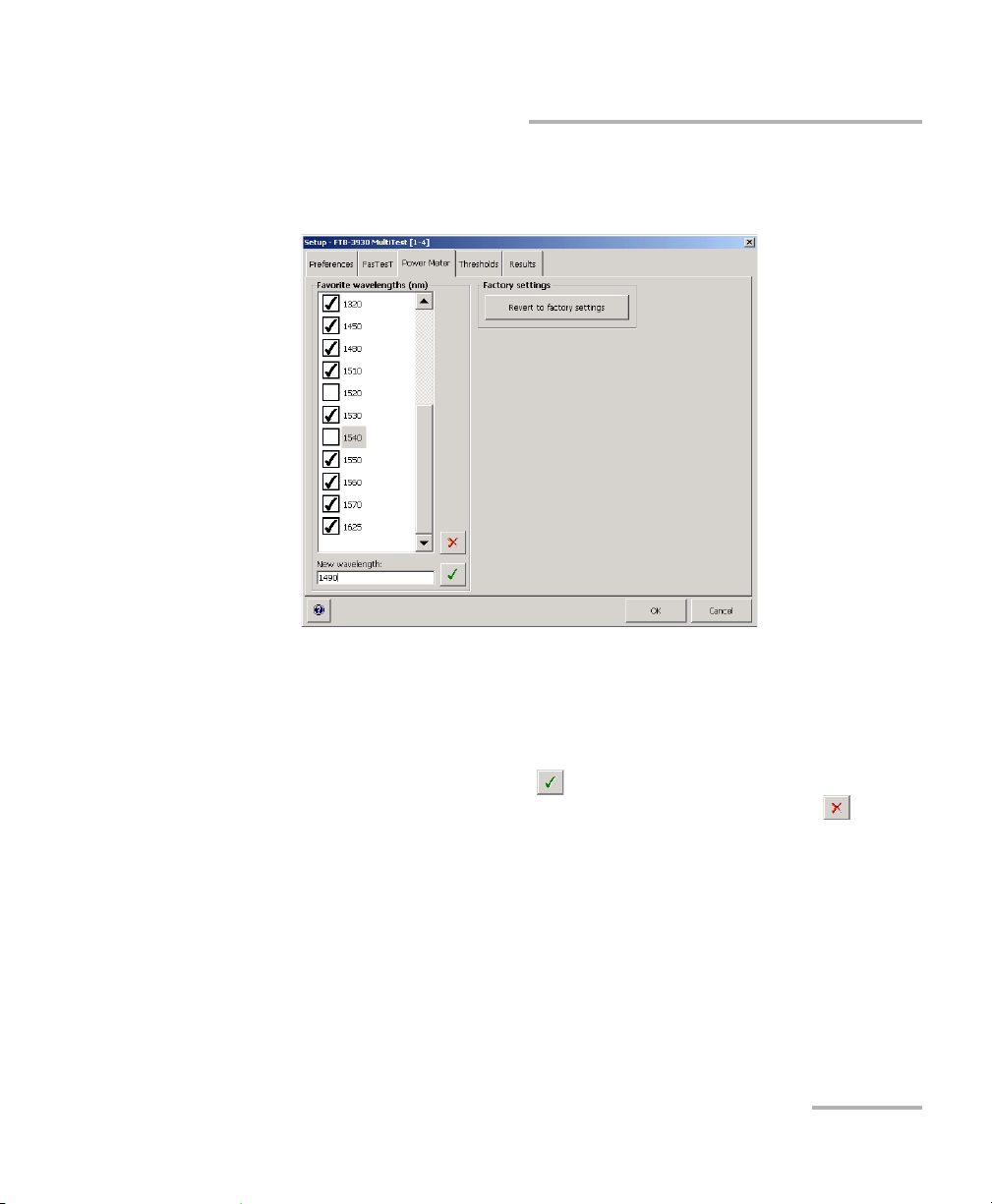
To customize the list of favorite and selected wavelengths:
1. From the button bar, press Setup, then select the Power Meter tab.
2. Scroll through the list.
3. Press on the highlighted wavelength to select/deselect it. An X appears
beside selected wavelengths.
4. If a wavelength does not appear on the list, enter its value in the New
wavelength box and press (or Add in the case of the FTB-200 v2).
You can also remove a wavelength from the list by pressing (or
Delete in the case of the FTB-200 v2).
5. Repeat these steps for other wavelengths as necessary.
6. Press OK to return to the main window.
To revert to the factory-default list:
1. From the button bar, press Setup, then select the Power Meter tab.
2. Press Revert to factory settings.
Multifunction Loss Tester 21
Page 28

Measuring Power or Loss
Nulling Electrical Offsets
Nulling Electrical Offsets
Temperature and humidity variations affect the performance of electronic
circuits and optical detectors. Nulling the electrical offsets eliminate these
effects.
Your unit has been designed not to require offset nulling under normal
operation, but you should perform it whenever environmental conditions
change significantly or when measuring very low power values.
IMPORTANT
Light must not reach detectors when nulling offsets. Always use an
EUI or protective screw cap. Do not use a soft rubber cover.
Note: Starting a nulling automatically deactivates all light sources on the unit.
To perform an offset nulling:
1. From the main window, select the Power Meter tab.
2. Press Nulling.
3. Tighten the protective caps on the power meter and F
press OK.
The nulling process takes approximately 10 seconds. Nulling status is
indicated in the data display. If light is still detected, you will need to
place the caps properly and restart.
22 FTB-3930
ASTEST ports, then
Page 29
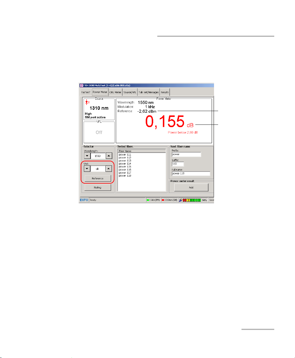
Measuring Power or Loss
Reference
power
Measured loss
Referencing Your Power Meter to a Source
Referencing Your Power Meter to a Source
In reference mode, your unit displays the loss created by the fiber under
test only, since it subtracts a reference value from the measured power.
In the illustration, the reference value (-2.62 dBm) is subtracted from the
actual power measured (-2.465 dBm).
Note: The reference value you set for each wavelength remains in memory until a
new one is set for the same wavelength, even when you turn the unit off.
Multifunction Loss Tester 23
Page 30
Measuring Power or Loss
FTB-3930
MULTITEST
Light
source
Power
meter
Adapter
Reference
patchcord
FTB-3930
MULTITEST
Light
source
Power
meter
Adapter
Reference
patchcord
Bulkhead
adapter
Reference
patchcord
Referencing Your Power Meter to a Source
To reference the power meter to a source:
1. From the main window, select the Power Meter tab.
2. Check your fibers and clean them properly for optimum performance
(see Cleaning and Connecting Optical Fibers on page 12).
3. Using one of the following methods, connect a light source to the
power meter port of your unit.
One single reference patchcord
Two reference patchcords and a bulkhead adapter
4. Activate the source at the desired wavelength.
24 FTB-3930
Page 31

Measuring Power or Loss
Referencing Your Power Meter to a Source
5. Match the power meter wavelength with the source wavelength as
follows:
Scroll through the Wavelength list to switch between favorite
wavelengths of your power meter (see Defining the List of Favorite
Wavelengths on page 20).
6. Scroll through the Unit list until you get dB units to retrieve the last
saved reference.
OR
Press Reference to save the current power as the new reference.
Reference power appears (in dBm) and current loss is automatically
switched to dB.
7. Repeat the procedure for each wavelength you want to reference.
Multifunction Loss Tester 25
Page 32

Measuring Power or Loss
Measuring Power or Loss
Measuring Power or Loss
Measuring absolute power or link loss is done the same way, except for the
referencing step. You can take power or loss measurements and save them
for further analysis.
Connect high-power live fiber to the power meter port only.
To perform power or loss measurements:
1. If necessary, perform an offset nulling (see Nulling Electrical Offsets on
page 22).
2. From the main window, select the Power Meter tab.
CAUTION
3. Check your fibers and clean them properly (see Cleaning and
Connecting Optical Fibers on page 12).
4. For loss measurements, reference your power meter to a light source
(see Referencing Your Power Meter to a Source on page 23), then
deactivate the light source.
5. If you have used a single reference patchcord, disconnect it from the
power meter port only, then attach a second reference patchcord to
the power meter.
OR
If you have used two reference patchcords, disconnect both of them at
the bulkhead.
26 FTB-3930
Page 33

Measuring Power or Loss
Reference
patchcord
Reference
patchcord
FTB-3930
MULTITEST
Light
source
Power
meter
Adapter
Fiber
under test
Bulkhead
adapter
Bulkhead
adapter
Measuring Power or Loss
6. Using bulkhead adapters or the system patch panels, connect a fiber
under test to reference patchcords attached to the light source and
power meter.
7. Activate the source at the desired wavelength.
8. Match the power meter wavelength with the source wavelength as
follows:
Scroll through the Wavelength list to switch between favorite
wavelengths of your power meter (see Defining the List of Favorite
Wavelengths on page 20).
If the unit detects a modulated signal, it beeps and the signal frequency
is indicated in the status bar.
9. Scroll through the Unit list to select the desired power (W or dBm) or
loss (dB) unit.
Multifunction Loss Tester 27
Page 34

Measuring Power or Loss
Measuring Power or Loss
10. Add the displayed values to the Teste d fib e rs list if you want. If
auto-save is activated (see Customizing Your Multifunction Loss Tester
on page 9), results are automatically saved after adding them to the list.
10a.Change the displayed cable and fiber names as needed.
10b.Press Add to save the value along with wavelength, reference
power, date and time. The fiber name will increment
automatically, ready to save the next value.
For details about viewing results, see Managing Test Results on
page 49.
11. Repeat the procedure for other wavelengths.
28 FTB-3930
Page 35

6 Measuring Optical Return Loss
FTB-3930
MULTITEST
ORL meter port
Measured ORL
(positive value)
Current ORL
wavelength
ORL meter
sensitivity
Value under
threshold
Add current value
to Te s t ed f ib e r s
(to actually save
data, press Save
on function bar)
Set reference using
ORL calibrated patchcord (best)
Set reference using
any patchcord
Change name of
next saved fiber
Switch between
singlemode
wavelengths
Calibrate ORL meter
sensitivity
Optical return loss (ORL) is the total effect of multiple reflections and
scattering events within a fiber-optic system.
The FTB-3930 Multifunction Loss Tester is equipped with an ORL meter to
measure ORL for singlemode fibers. The ORL meter uses the F
(singlemode) port only.
The following functions are available on your ORL meter:
ASTEST SM
Multifunction Loss Tester 29
Page 36
Measuring Optical Return Loss
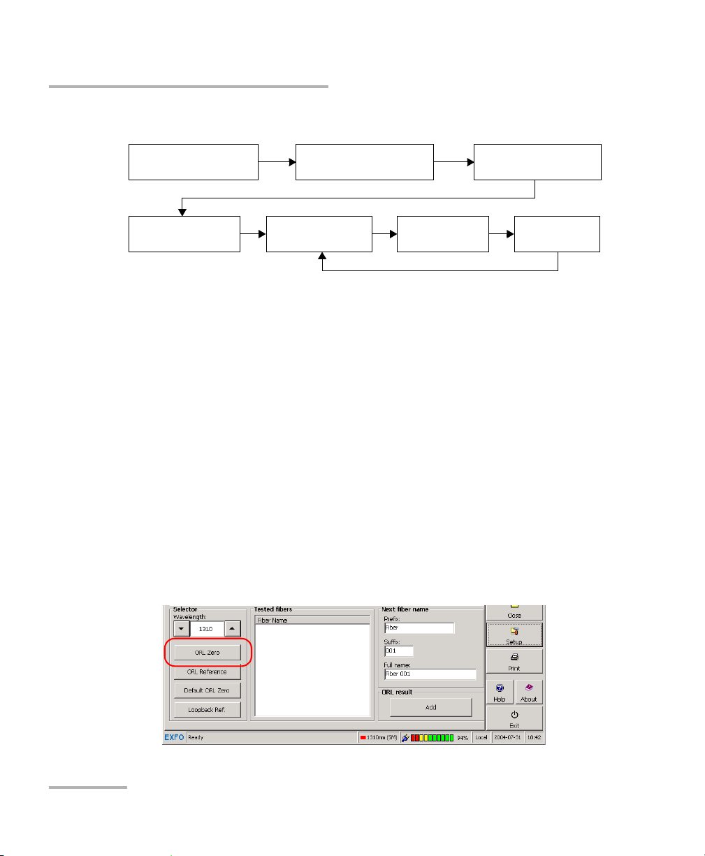
Set
ORL zero
Measure
ORL
Save
results
Perform
ORL reference
Set up thresholds
(see page 16)
Null offsets
(see page 22)
Select
wavelength
Performing ORL Reference and Setting ORL Zero Value
The ORL measurement procedure is outlined below:
Performing ORL Reference and Setting ORL
Zero Value
The ORL zero measurement eliminates the effects of backreflection on the
link before the component under test, so your unit displays only the
backreflection of this component.
You should set a new ORL zero:
when you change the measurement patchcord (the one connected to
the DUT, not the reference patchcord)
when you remove a connection between the unit and mandrel
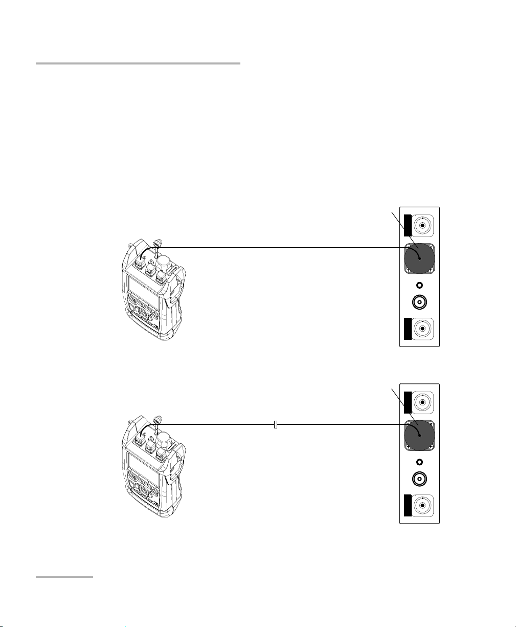
To set the ORL zero value (all wavelengths at once):
1. From the main window, select the ORL Meter tab.
2. Press ORL Zero.
30 FTB-3930
Page 37

Measuring Optical Return Loss
Termination Component
under test
FTB-3930
MULTITEST
Performing ORL Reference and Setting ORL Zero Value
3. Connect a patchcord to the FASTEST SM port.
4. Terminate the fiber as close as possible before the component under
test. Wrap it at least 10 turns around a mandrel or small diameter tool,
adding turns until the reading stabilizes.
5. Press OK to save the ORL zero value, then remove the termination.
To revert to the factory-default ORL zero value:
1. From the main window, select the ORL Meter tab.
2. Press Default ORL Zero.
Multifunction Loss Tester 31
Page 38

Measuring Optical Return Loss
Performing and Saving ORL Measurements
Performing and Saving ORL Measurements
You can define ORL thresholds (see Setting Pass/Fail Thresholds on
page 16) before or after measuring ORL. ORL values below thresholds are
displayed in red.
To m ea s ur e O R L:
1. If necessary, perform an offset nulling (see Nulling Electrical Offsets on
page 22).
2. From the main window, select the ORL Meter tab.
3. Scroll through the Wa v e length list to select a singlemode wavelength.
4. Verify your patchcords and clean them properly (see Cleaning and
Connecting Optical Fibers on page 12).
Note: If the F
EXFO’s optional ORL calibrated patchcord.
32 FTB-3930
ASTEST SM port of your unit is equipped with an APC connector, use
Page 39

Measuring Optical Return Loss
Per f orming and S aving ORL Measurements
5. Connect one end of a patchcord to the FASTEST SM port of your unit
leaving the other end unconnected.
6. Perform an ORL reference as follows:
Note: During the reference, the patchcord end should remain in the air;
reflections occurring at a fiber-to-air interface correspond to a constant of
14.7 dB.
Press ORL Reference.
Multifunction Loss Tester 33
Page 40

Measuring Optical Return Loss
FTB-3930
MULTITEST
Te rm i n at i o nComponent
under test
Performing and Saving ORL Measurements
7. Pe rfor m an ORL zero measurement (see Performing ORL Reference
and Setting ORL Zero Value on page 30).
8. Terminate the fiber as close as possible after the component under
test. Wrap it at least 10 turns around a mandrel or small diameter tool,
adding turns until the reading stabilizes.
Note: Avoid bending the fiber between the unit and the termination point.
The displayed value represents the ORL of the component under test.
9. Add the displayed values to the Test e d fi b ers list if you want. If
auto-save is activated (see Customizing Your Multifunction Loss Tester
on page 9), results are automatically saved (along with wavelength,
date and time) after adding them to the list.
9a. Change the displayed cable and fiber names as needed.
9b. Press Add. The fiber name will increment automatically, ready to
save the next value.
For details about viewing results, see Managing Test Results on
page 49.
10. Repeat procedure for other wavelengths if necessary.
34 FTB-3930
Page 41

7 Performing Automated
FTB-3930
MULTITEST
FASTEST singlemode (SM) and
multimode (MM) ports
Perform
F
ASTEST
Perform
reference
Save
results
Set ORL zero
(see page 30)
Null offsets
(see page 22)
Set up
F
ASTEST
Set up thresholds
(see page 16)
IL/ORL/Length Measurements
(FasTesT)
FASTEST allows you to perform 2- or 3-wavelength bidirectional loss and
ORL tests for singlemode fibers, or 2-wavelength loss tests for multimode
fibers, in 10 seconds (including fiber length measurement).
F
ASTEST is useful in high-fiber-count installations. Activated at the touch of a
button, F
ASTEST cuts down on training time and provides error-free results.
To use F
ASTEST, you need a compatible unit (such as FTB-3930, FOT-930,
FOT-920 or FTB-3920, but not the FOT-910). The unit at the remote end is
only used to establish references. It then waits for commands from the unit
initiating F
The F
ASTEST (master).
ASTEST procedure is outlined below:
Multifunction Loss Tester 35
Page 42

Performing Automated IL/ORL/Length Measurements (FasTesT)
Setting Up the FasTest
Setting Up the FasTest
You can configure the FASTEST on the master unit only. The remote unit will
automatically adapt to these parameters (F
unit are ignored).
Setup includes the following elements:
Port and DUT (fiber) type: multimode FASTEST will not include ORL.
Compatibility: select FOT-930 / FTB-3930 for fast, two- or
three-wavelength testing including ORL (it requires two
FOT-930/FTB-3930). Use FOT-920 / FTB-3920 when other unit is an
FOT-920 or FTB-3920.
Mode/wavelengths: select one or more wavelengths for the FASTEST.
Depending on your choice, the F
measurements. Selecting FTTx Custom or FTTx All allows you to
define upstream and downstream wavelengths.
Unit location: in FTTx mode, you specify if the master unit is closer to
the CO (or to the premises) than the remote unit.
ASTEST parameters on remote
ASTEST will include loss and/or ORL
36 FTB-3930
Page 43

Performing Automated IL/ORL/Length Measurements (FasTesT)
Setting Up the FasTest
To set up the FasTesT:
1. From the button bar, press Setup, then select the F
ASTEST tab.
2. Select the F
ASTEST parameters.
To revert to factory-default FasTesT settings:
1. From the button bar, press Setup, then select the F
ASTEST tab.
2. Press Revert to factory settings.
Multifunction Loss Tester 37
Page 44
Performing Automated IL/ORL/Length Measurements (FasTesT)
System
under test
Connector
mating
Connector
mating
System
under test
Connector
mating
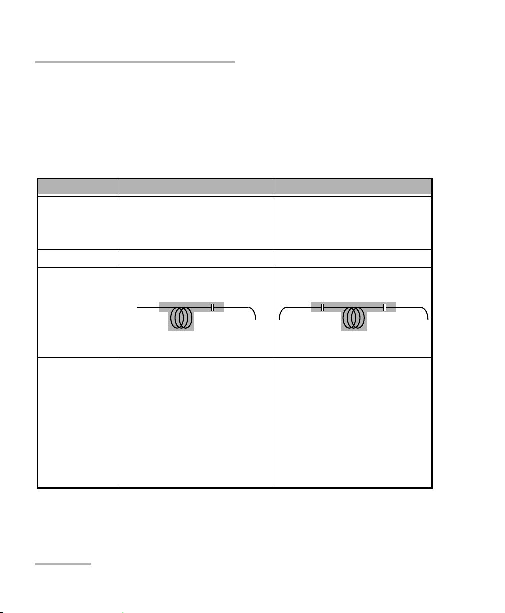
Referencing Units for FasTesT
Referencing Units for FasTesT
Referencing subtracts the loss caused by the test setup components from
the overall loss measured during F
loss inserted by the system under test alone.
Two referencing methods are available:
Side-by-Side Method (Best) Loopback Method
ASTEST. The final result represents the
Description Reference taken with both units
together using their F
ASTEST ports.
Slightly more accurate value than
Reference taken separately on
each unit (F
ASTEST port connected
to power meter port).
loopback method.
Location of units Must be at same location. Can be at different locations.
Loss included in
F
ASTEST result
Elements to
consider
Loss due to system under test and
one connector mating.
Includes neither an ORL
reference nor an ORL zero
measurement. To obtain them,
use the ORL Meter pane (see
Performing ORL Reference and
Loss due to system under test and
the two connector matings.
When measuring ORL (F
ASTEST or
ORL meter), accounts for
connector loss and adjusts ORL
calibration accordingly.
Not recommended for short links.
Setting ORL Zero Value on
page 30).
With multiple referencing, you
may coordinate an FTB-3930 with
up to 10 FOT-930 units.
38 FTB-3930
Page 45

Performing Automated IL/ORL/Length Measurements (FasTesT)
Reference
patchcord
Bulkhead
adapter
Reference
patchcord
FTB-3930
MULTITEST
FTB-3930
MULTITEST
Referencing Units for FasTesT
To perform a side-by-side reference:
1. On the master unit (the one initiating the test), select the F
ASTEST tab.
2. In the Reference pane, select the Side-by-side reference type. The
data display shows previous reference values (if any) for the currently
connected remote unit.
IMPORTANT
With its multiple referencing feature, your unit saves the last 10
side-by-side references for each DUT type and compatibility mode.
3. Connect both units through their F
ASTEST ports, using two reference
patchcords and a bulkhead adapter.
Multifunction Loss Tester 39
Page 46

Performing Automated IL/ORL/Length Measurements (FasTesT)
Serial number of
unit on other side
Referencing Units for FasTesT
4. Press Take Reference. After a few seconds, the unit displays new
reference values for each wavelength on both units. If values are not
acceptable, try to clean connectors and repeat this step.
5. Disconnect the two patchcords from the bulkhead only and connect
them to the fiber under test (using bulkhead adapters or the system
patch panels).
IMPORTANT
You can turn off the unit without losing the reference.
If you disconnect the patchcords from the FASTEST ports, you
must take a new reference.
40 FTB-3930
Page 47

Performing Automated IL/ORL/Length Measurements (FasTesT)
FTB-3930
MULTITEST
Reference
patchcord
Adapter
Referencing Units for FasTesT
To perform a loopback reference:
1. On the master unit (the one initiating the test), select the F
ASTEST tab.
2. In the Reference pane, select the Loopback reference type. The data
display shows previous reference values (if any).
3. Connect a reference patchcord from the F
meter adapter.
ASTEST port to the power
Multifunction Loss Tester 41
Page 48

Performing Automated IL/ORL/Length Measurements (FasTesT)
Referencing Units for FasTesT
4. Press Take Reference. After a few seconds, the unit displays new
reference values for each wavelength. If values are not acceptable, try
to clean connectors and repeat this step.
5. Disconnect the reference patchcord from the power meter adapter
only and connect it to the fiber under test.
IMPORTANT
You can turn off the unit without losing the reference.
If you disconnect the patchcord from the FASTEST port, you must
take a new reference.
6. Repeat the procedure with the second unit.
42 FTB-3930
Page 49

Performing Automated IL/ORL/Length Measurements (FasTesT)
Performing the FasTesT
Performing the FasTesT
Although FASTEST requires two units (one at each end of the fiber under
test), you initiate it from only one (the master). Both units use F
settings from the master unit.
To perform a FasTesT:
Unit A (Master) Unit B
ASTEST
1. If necessary, null the offsets (see
Nulling Electrical Offsets on page 22).
2. Clean your fibers properly (see
Cleaning and Connecting Optical
Fibers on page 12).
3. Set up the F
ASTEST (see Setting Up the
FasTest on page 36).
4. If you are testing ORL, perform an
ORL zero measurement from the ORL
Meter pane (see Performing ORL
Reference and Setting ORL Zero Value
on page 30).
5. Reference your unit (see Referencing
Units for FasTesT on page 38).
1. If necessary, null the offsets.
2. Clean your fibers properly.
3. If you are testing ORL, perform an
ORL zero measurement from the ORL
Meter pane.
4. Reference your unit.
Multifunction Loss Tester 43
Page 50

Performing Automated IL/ORL/Length Measurements (FasTesT)
Reference
patchcord
Fiber
under test
Reference
patchcord
Bulkhead
adapter
Bulkhead
adapter
FTB-3930
MULTITEST
FTB-3930
MULTITEST
Performing the FasTesT
Unit A (Master) Unit B
6. Connect reference patchcord to fiber
under test (as shown):
5. Connect reference patchcord to fiber
under test (as shown):
44 FTB-3930
Page 51

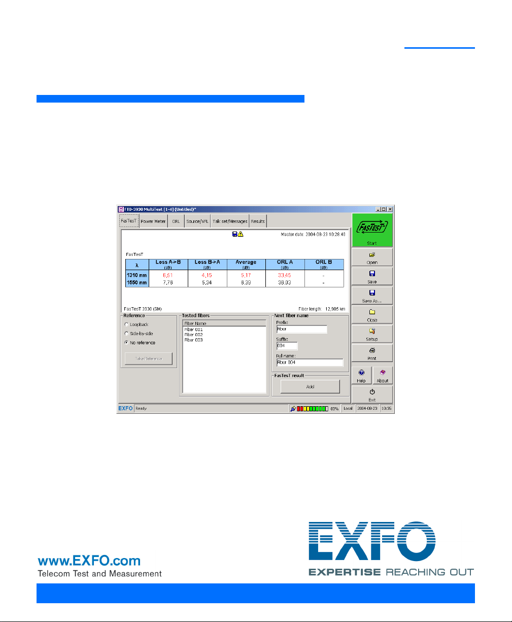
Performing Automated IL/ORL/Length Measurements (FasTesT)
Measured values
Calculated fiber length
Add current value to Te s te d
fibers (to actually save data,
press Save on function bar)
Change name of
next added fiber
Indicates
unsaved results
Value unde r
threshold (in red)
Indicates results not added
to Tes t e d f i b er s list
Standard View
Measured values
Value unde r
threshold (in red)
FTTx View
Performing the FasTesT
Unit A (Master) Unit B
7. From the button bar, press FASTEST (large green button).
The units establish communication and automated tests begin. Measurements
appear on both units as they are taken.
Multifunction Loss Tester 45
Page 52

Performing Automated IL/ORL/Length Measurements (FasTesT)
Performing the FasTesT
Unit A (Master) Unit B
8. Add the displayed values to the
Test e d fi b ers list if you want. If
automatic save was activated for one
or both units (see Customizing Your
Multifunction Loss Tester on page 9),
results are already added to the list.
8a. Change the displayed cable and
fiber names as needed.
8b. Press Add. The fiber name
increments automatically, ready
to save the next value.
If you are not satisfied with the results,
press F
ASTEST and redo the test.
46 FTB-3930
Page 53

Performing Automated IL/ORL/Length Measurements (FasTesT)
Measured
values
Calculated fiber
length
Add current value to Te st ed
fibers (to actually save data,
press Save on function bar)
Change
name of
next added
fiber
Performing the FasTesT
For details about viewing FASTEST results, see Managing Test Results on
page 49.
Multifunction Loss Tester 47
Page 54

Page 55

8 Managing Test Results
Viewing and Deleting Results
You can save all your results (FASTEST, power/loss and ORL) on your
platform, along with references and date/time of tests. You will save and
recall this data according to cable names (or any Windows file name).
IMPORTANT
The date and time of FASTEST references are not saved. They are
displayed with the results immediately after the test only.
Before or after saving the current file, you can view and edit results at any
time (as long as a result was added to a Tes t ed fi b ers list).
To view and process test results:
From the Multifunction Loss Tester application’s main window, select the
Results tab. The following functions are available when viewing results:
Multifunction Loss Tester 49
Page 56

Managing Test Results
Shortcut to
result sections
Result sections
To copy all results to
Windows clipboard (for
pasting as plain text)
To select current
threshold group (you can
also click on section title)
To modify job or cable
information (you can also
click on section title)
FTB-500
To mark fiber for deletion
Click on link to edit
fiber ID or comments
To delete results for
selected (checked) fibers
Result
exceeding
threshold
Viewing and Deleting Results
50 FTB-3930
Page 57

Managing Test Results
To modify job or cable
information
To select current
threshold group
To mark fiber for
deletion
FTB-200 v2
Viewing and Deleting Results
IMPORTANT
The threshold group you select will remain associated with the file,
even if you change the default group. However, if you change
values in the selected group, they will apply to your results.
Note: For more accuracy, the loss average is always calculated from loss values
in W and then converted to dB.
Multifunction Loss Tester 51
Page 58

Managing Test Results
FTB-500
Customizing Result Display
Customizing Result Display
For the FTB-500, you can customize the following elements:
Power unit: will affect the Results tab and the printed report, but not
the different test tabs.
Display FASTEST reference: when selected, the FASTEST references will
be shown on the Results tab.
Custom boxes: sets the names of fields in the Edit Job Information
and Edit Cable Information windows. When you change the field
name, data in this field is kept.
For the FTB-200 v2, in the results display, you can customize the custom
boxes, that set the names of fields in the Edit Job Information and Edit
Cable Information windows. When you change the field name, data in
this field is kept.
You can also define default initial cable and fiber names. For details, see
Setting Autonaming Scheme on page 14.
To customize the display of results:
1. From the main window, press Setup, then select the Results tab.
52 FTB-3930
Page 59

2. Set parameters and press OK.
From Edit Job
Information
From Edit Cable
Information
FTB-200 v2
Managing Test Results
Customizing Result Display
Multifunction Loss Tester 53
Page 60

Managing Test Results
Change default
report title
Current logo name
and preview
Select logo
(GIF or JPEG only)
Select information
to include
in report
Display report
preview
Obtain help
about reports
Customizing and Printing Reports (FTB-500)
Customizing and Printing Reports (FTB-500)
The FTB-3930 Multifunction Loss Tester application allows you to print
detailed reports including your custom selection of OLTS data (F
ORL and power results with cable and job information).
ASTEST,
Note: Saving a report including all items, a default title and no logo is equivalent
54 FTB-3930
You can also save the report as an HTML or XML file to view or print it later
using any HTML or XML browser.
to using the Save As button to save as HTML in the main window.
When you select information to include, consider the following:
System Information and Job Information contain details from the
Job Information section.
FasTesT includes values from the Loss pane (except for references)
and ORL pane (except for manual ORL values).
Results exceeding thresholds are indicated with a “!”.
Page 61

Managing Test Results
Customizing and Printing Reports (FTB-500)
To print a report:
1. From the main window, press Print.
2. Enter a report title and press Browse to select a logo if desired.
3. Select items to include in the report, as follows:
To add or remove an item, check or clear the corresponding box.
To add all items, press Select All.
To remove all items, press Clear All.
4. If desired, press Preview to view the report before printing.
5. Press Print. For information about printer parameters, refer to your
printer’s user guide or to the Microsoft Windows documentation.
To save a report to a file:
1. Perform steps 1 to 4 in the above procedure.
2. Press Save Report, then select a name and file format (HTML or XML).
Multifunction Loss Tester 55
Page 62

Page 63

9 Using a Light Source
FTB-3930
MULTITEST
Source singlemode (SM) and
multimode (MM) ports
Your unit may contain two source ports: a 2- or 3-wavelength singlemode
port and a 2-wavelength multimode port, depending on the configuration.
The source signal can be continuous (CW or high-power) or modulated
(270 Hz, 1 kHz or 2 kHz) and uses the F
CW signal (the default): constant power over the temperature range,
but about 3 dB lower than maximum.
High-power signal: reaches maximum power, but its power slightly
varies over the temperature range.
WARNING
When a source is active, its port emits invisible laser radiation.
Avoid exposure and do not stare directly into the beam. Ensure that
any unused port is properly protected with a cap.
ASTEST ports.
If you switch to power meter or ORL meter, a Source status pane is
always displayed.
When you switch sources, the modulation remains the same. It is
indicated in the data display.
Only one source/wavelength may be active at a time. The active port
(SM or MM) is indicated in the data display.
The source status is indicated with a LED in the status bar and on the
platform front panel.
Note: The platform front panel always shows the source, VFL, ORL meter or talk
set port status (even when you use other applications).
Multifunction Loss Tester 57
Page 64

Using a Light Source
Data display
Status LED
Power switch
To activate a light source:
1. Connect the fiber under test to the source port (see Cleaning and
Connecting Optical Fibers on page 12).
2. From the main window, select the Source/VFL tab (units with a VFL)
or the Source tab (units with no VFL).
58 FTB-3930
Page 65

Using a Light Source
Power button
Data display
Status LED
FTB-200 v2
3. In the Source pane, select a wavelength using the Wa v e l e n gth dial
(Use the + and - buttons in the case of the FTB-200 v2 platform).
4. Slide the Power switch to On (or press the On/Off button in the case of
the FTB-200 v2 platform).
To deactivate a light source:
Slide the Power switch to Off (or press the On/Off button in the case of the
FTB-200 v2 platform).
To change the signal modulation:
1. Activate the source if you want.
2. Select a modulation using the Modulation dial (Use the + and -
buttons in the case of the FTB-200 v2 platform).
Multifunction Loss Tester 59
Page 66

Page 67

10 Identifying Fiber Faults
FTB-3930
MULTITEST
Visual fault locator (VFL) port
Visually
The visual fault locator (VFL) helps you identify bends, faulty connectors,
splices and other causes of signal loss.
From its dedicated port, the VFL emits a red signal which becomes visible
at the location of a fault on the fiber. This signal can be continuous
(CW, the default) or blinking (1 Hz).
WARNING
When the VFL is active, the VFL port emits visible laser radiation.
Avoid exposure and do not stare directly into the beam. Ensure that
any unused port is properly protected with a cap.
If you switch to power meter or ORL meter, a VFL status pane is always
displayed.
The VFL status is indicated with a LED in the status bar and on the
platform front panel.
Note: The platform front panel always shows the source, VFL, ORL meter or talk
set port status (even when you use other applications).
Multifunction Loss Tester 61
Page 68

Identifying Fiber Faults Visually
Data display
Status LED
Power switch
To activate the VFL and inspect a fiber:
1. Connect the fiber under test to the VFL port (see Cleaning and
Connecting Optical Fibers on page 12).
2. From the main window, select the Source/VFL tab.
3. In the VFL pane, slide the Power switch to On.
4. To switch between blinking (1 Hz) and continuous (CW) signals, use
the Modulation dial.
5. Without looking directly into the beam, examine the fiber. If light is
coming out of the rubber jacket or on the side of the ferrule, the fiber is
defective.
6. Deactivate the VFL by sliding the Power switch to Off.
62 FTB-3930
Page 69

11 Communicating with Other
Users
Your Multifunction Loss Tester offers two ways to communicate:
text messages
voice (via the optional talk set)
Sending and Receiving Text Messages
To facilitate communication between opposite ends of a fiber (especially
on models with no talk set), you may send text messages to compatible
units (such as FOT-930, FTB-3930, FOT-920 or FTB-3920) through their
F
ASTEST ports.
It is possible to send a predefined message or to write one of your own
(maximum 30 characters). However, custom messages are not kept in
memory.
IMPORTANT
The messaging feature does not work with the talk set port.
The messaging feature will not work if both units try to send a
message at the same time.
You cannot use other features while sending or receiving a
message.
You cannot cancel the operation.
To send a text message:
1. Connect the units at each end of the same fiber via their F
Multifunction Loss Tester 63
ASTEST ports.
Page 70

Communicating with Other Users
FTB-3930
MULTITEST
List of sent
and received
messages
Status display
(with port)
Sending and Receiving Text Messages
2. From the main window, select the Talk set/Messages tab (units with a
talk set) or the Messages tab (units with no talk set and FTB-200 v2
units).
64 FTB-3930
Page 71

Communicating with Other Users
Sending and Receiving Text Messages
3. Ensure that the port indicated (SM or MM) is the one you use.
Otherwise, do as follows:
3a. In the function bar, press Setup, then select the F
3b. Change the F
ASTEST port, then return to the Messages pane.
ASTEST tab.
4. Scroll through the Predefined messages list and select a message.
OR
Enter a custom message in the New message text box.
5. Press the Send button next to your type of message (predefined or
new).
After a few seconds, your message will automatically appear on the
receiving unit (if its Multifunction Loss Tester application runs) and on the
Message log pane. If an incompatible unit (or no unit) is detected at the
other end, or if the F
ASTEST port of the receiving unit is in use, an error
message will appear.
When you receive a message:
Your unit emits a short beep and displays the received message.
Press Close to clear the display and return to your previous function.
Press Reply to access the Messages tab and reply to the message. You
will then need to return to your previous function manually. However,
your last readings will be lost.
Note: If the message was written with a language not supported by your unit, you
will see unreadable characters only.
Multifunction Loss Tester 65
Page 72

Communicating with Other Users
FTB-3930
MULTITEST
Tal k s et p o rt
Communicating by Voice
Communicating by Voice
With the optional talk set, you can establish full-duplex digital voice
communication over a dedicated fiber, even while other functions are in
use.
The talk set provides adjustable headset volume and uses a dedicated port.
It is not compatible with the FOT-920 or FTB-3920 talk sets.
Note: You may use any commercially available headset equipped with a
microphone. It is also compatible with the GP-92B speakerphone.
While communication is established, the actions and displays of
each unit may differ as follows:
You can send or receive a call at any time, except during a FASTEST. To
receive a call, you must be running the Multifunction Loss Tester
application.
Once communication is established, it will be maintained even if you
use the unit’s other test tools (including F
If communication is lost, calling unit will automatically try to
ASTEST).
reestablish communication.
66 FTB-3930
Page 73

Communicating with Other Users
FTB-3930
MULTITEST
Headset
volume
Status
display
Communicating by Voice
To communicate between units:
Calling Unit Receiving Unit
1. Connect the calling unit to one end of
the fiber via its talk set port, and plug
in your headset.
2. From the main window, select the
Talk set/Messages tab (Messages tab
for the FTB-200 v2 unit).
1. Connect the receiving unit to the
other end of the fiber via its talk set
port, and plug in your headset.
Multifunction Loss Tester 67
Page 74

Communicating with Other Users
Communicating by Voice
Calling Unit Receiving Unit
3. Press Talk . Your unit establishes
communication with receiving unit.
When receiving the call, the unit
beeps. A phone icon appears to
indicate that communication is
established.
If no compatible unit is detected at
the other end, a message appears.
4. Talk to the receiving unit. 2. Simply answer (no need to press a
key).
5. To end the communication, press
End from the Talk set pane.
3. To end the communication, press
End from the Talk se t pane.
To adjust the headset volume (calling or receiving unit):
From the Ta lk set pane, move the Headset volume slider to the top
(volume increase) or to the bottom (volume decrease).
You cannot adjust or mute the ring sound.
68 FTB-3930
Page 75

12 Maintenance
To help ensure long, trouble-free operation:
Always inspect fiber-optic connectors before using them and clean
them if necessary.
Keep the unit free of dust.
Clean the unit casing and front panel with a cloth slightly dampened
with water.
Store unit at room temperature in a clean and dry area. Keep the unit
out of direct sunlight.
Avoid high humidity or significant temperature fluctuations.
Avoid unnecessary shocks and vibrations.
If any liquids are spilled on or into the unit, turn off the power
immediately, disconnect from any external power source, remove the
batteries and let the unit dry completely.
The use of controls, adjustments and procedures, namely for
operation and maintenance, other than those specified herein may
result in hazardous radiation exposure or impair the protection
provided by this unit.
WARNING
Cleaning EUI Connectors
Regular cleaning of EUI connectors will help maintain optimum
performance. There is no need to disassemble the unit.
IMPORTANT
If any damage occurs to internal connectors, the module casing will
have to be opened and a new calibration will be required.
Multifunction Loss Tester 69
Page 76

Maintenance
Push
Tur n
Pull
3
4
5
Cleaning EUI Connectors
Looking into the optical connector while the light source is active
WILL result in permanent eye damage. EXFO strongly recommends
to TURN OFF the unit before proceeding with the cleaning
procedure.
To clean EUI connectors:
1. Remove the EUI from the instrument to expose the connector
baseplate and ferrule.
2. Moisten a 2.5 mm cleaning tip with one drop of isopropyl alcohol
(alcohol may leave traces if used abundantly).
WARNING
3. Slowly insert the cleaning tip into the EUI adapter until it comes out on
the other side (a slow clockwise rotating movement may help).
4. Gently turn the cleaning tip one full turn, then continue to turn as you
withdraw it.
5. Repeat steps 3 to 4 with a dry cleaning tip.
Note: Make sure you don’t touch the soft end of the cleaning tip.
70 FTB-3930
Page 77

Maintenance
Cleaning EUI Connectors
6. Clean the ferrule in the connector port as follows:
6a. Deposit one drop of isopropyl alcohol on a lint-free wiping cloth.
IMPORTANT
Isopropyl alcohol may leave residues if used abundantly or left to
evaporate (about 10 seconds).
Avoid contact between the tip of the bottle and the wiping cloth,
and dry the surface quickly.
6b. Gently wipe the connector and ferrule.
6c. With a dry lint-free wiping cloth, gently wipe the same surfaces to
ensure that the connector and ferrule are perfectly dry.
6d. Verify connector surface with a portable fiber-optic microscope
(for example, EXFO’s FOMS) or fiber inspection probe (for
example, EXFO’s FIP).
7. Put the EUI back onto the instrument (push and turn clockwise).
8. Throw out cleaning tips and wiping cloths after one use.
Multifunction Loss Tester 71
Page 78

Maintenance
Cleaning Detector Ports
Cleaning Detector Ports
Regular cleaning of detectors will help maintain measurement accuracy.
Always cover detectors with protective caps when unit is not in use.
To clean detector ports:
1. Remove the protective cap and adapter (FOA) from the detector.
2. If the detector is dusty, blow dry with compressed air.
3. Being careful not to touch the soft end of the swab, moisten a cleaning
tip with only one drop of isopropyl alcohol.
Alcohol may leave traces if used abundantly. Do not use bottles that
distribute too much alcohol at a time.
IMPORTANT
IMPORTANT
4. While applying light pressure (to avoid breaking the detector window),
gently rotate the cleaning tip on the detector window.
5. Repeat step 4 with a dry cleaning tip or blow dry with compressed air.
6. Discard the cleaning tips after one use.
72 FTB-3930
Page 79

Maintenance
Cleaning VFL-Type Connectors
Cleaning VFL-Type Connectors
VFL-type connectors are fixed on your unit and can be cleaned using a
mechanical cleaner.
WARNING
Verifying the surface of the connector with a fiber-optic microscope
WHILE THE UNIT IS ACTIVE WILL result in permanent eye damage.
To clean a connector using a mechanical cleaner:
1. Insert the mechanical into the optical adapter, and push the outer shell
into the cleaner.
Note: The cleaner makes a clicking sound to indicate that the cleaning is done.
2. Verify connector surface with a portable fiber-optic microscope (for
example, EXFO’s FOMS) or fiber inspection probe (for
example, EXFO’s FIP).
WARNING
Only use an EXFO battery. Batteries from other suppliers could
result in serious damage to your unit, or personal injuries. Contact
EXFO for more information.
Multifunction Loss Tester 73
Page 80

Maintenance
Recalibrating the Unit
Do not throw batteries into fire or water and do not short-circuit
the batteries’ electrical contacts. Do not disassemble.
Recalibrating the Unit
EXFO manufacturing and service center calibrations are based on the
ISO/IEC 17025 standard (General Requirements for the Competence of
Testing and Calibration Laboratories). This standard states that calibration
documents must not contain a calibration interval and that the user is
responsible for determining the re-calibration date according to the actual
use of the instrument.
The validity of specifications depends on operating conditions. For
example, the calibration validity period can be longer or shorter depending
on the intensity of use, environmental conditions and unit maintenance, as
well as the specific requirements for your application. All of these elements
must be taken into consideration when determining the appropriate
calibration interval of this particular EXFO unit.
WARNING
Under normal use, the recommended interval for your FTB-3930
Multifunction Loss Tester is: one year.
For newly delivered units, EXFO has determined that the storage of this
product for up to six months between calibration and shipment does not
affect its performance (EXFO Policy PL-03).
74 FTB-3930
Page 81

Maintenance
Recycling and Disposal (Applies to European Union Only)
To help you with calibration follow-up, EXFO provides a special calibration
label that complies with the ISO/IEC 17025 standard and indicates the unit
calibration date and provides space to indicate the due date. Unless you
have already established a specific calibration interval based on your own
empirical data and requirements, EXFO would recommend that the next
calibration date be established according to the following equation:
Next calibration date = Date of first usage (if less than six months
after the calibration date) + Recommended calibration period (one
year)
To ensure that your unit conforms to the published specifications,
calibration may be carried out at an EXFO service center or, depending on
the product, at one of EXFO’s certified service centers. Calibrations at
EXFO are performed using standards traceable to national metrology
institutes.
Note: You may have purchased a FlexCare plan that covers calibrations. See the
Service and Repairs section of this user documentation for more
information on how to contact the service centers and to see if your plan
qualifies.
Note: The FlexCare warranty program includes Calibration/Verification packages
(see Service and Repairs on page 85).
Recycling and Disposal
(Applies to European Union Only)
For complete recycling/disposal information as per European Directive
WEEE 2012/19/UE, visit the EXFO Web site at www.exfo.com/recycle.
Multifunction Loss Tester 75
Page 82

Page 83

13 Troubleshooting
Solving Common Problems
Problem Possible Cause Solution
During offset nulling, you
get the following message:
“Light detected during
nulling.”
When using the power
meter, you get Power Too
Low or Power Too High.
When measuring ORL, you
get Too M u c h Po wer.
When measuring ORL, you
get ORL exceeds.
Light reaches at least one
detector (power meter or
F
ASTEST).
Power of the signal
received at the power
meter port is outside its
measurement range.
Measured reflected power
is higher than emitted
power. The ORL reference
is incorrect.
Reflection is below
sensitivity of ORL meter.
Ensure protective caps are
tightly screwed on F
and power meter ports and
perform the nulling again.
Do not use rubber cover.
Check the connections.
Ensure you use the proper
fiber and connector type and
that you use your power
meter within specifications.
Always perform ORL
reference before each ORL
measurement.
Perfo r m an ORL z e r o
measurement to increase the
sensitivity of the detector.
Ensure mandrel is correct and
that patchcord and
connectors are in good
condition.
ASTEST
Multifunction Loss Tester 77
Page 84

Troubleshooting
Solving Common Problems
Problem Possible Cause Solution
Unable to establish FASTEST
communication.
During F
ASTEST, you get a
message saying that
loopback reference was
not performed.
ORL values are inaccurate
for short fibers at 1310 nm
during a F
ASTEST.
Remote unit’s FASTEST
port is in use.
Remote unit is not
compatible.
Selected port on master
unit differs from actual
port to which fiber is
connected.
Compatibility set to
FOT-930 / FTB-3930
but remote unit is not
an FOT-930 or
FTB-3930.
Loopback reference was
selected, but not performed
(or reference is outdated).
— Measure ORL manually.
Wait until FASTEST
completes, turn source
and ORL meter off or exit
Probe mode (FOT-930).
Make sure remote unit
isan FOT-930, FTB-3930,
FOT-920 or FTB-3920.
Set the port (SM or MM)
correctlyin Setup (F
ASTEST
tab) on master unit.
Set the compatibility to
FOT-920 / FTB-3920 in
Setup (F
ASTEST tab) on
master unit.
Perform a loopback reference
before F
ASTEST measurement.
Unable to communicate
with an FOT-920 using the
talk set.
Unable to establish
connection with
Talk sets of the FOT-920 and
FOT-930/FTB-3930 are not
compatible.
Probe mode is activated on
remote unit(FOT-930 only).
Use text messaging instead.
Deactivate Probe mode.
compatible talk set.
78 FTB-3930
Page 85

Troubleshooting
Solving Common Problems
Problem Possible Cause Solution
Unable to send a text
message.
On Results tab, a box
indicates “Invld” instead of
a numerical value.
On Results tab, a box
indicates “- - - -” instead of
a numerical value.
When printing a report,
rightmost columns are not
printed.
Selected port differs
from actual port to
which fiber is
connected.
Receiving unit’s port is
in use.
Remote unit is not
compatible.
The application is unable to
calculate the F
ASTEST ORL
value (e.g., at 1310 nm for
short fibers).
The calculated value makes
no sense (e.g., negative
ORL value).
The Fiber ID column is too
wide. The width of this
column is determined with
the widest name.
On the sending unit, set
the correct port (SM or
MM) in Setup (F
ASTEST
tab).
Wait until FASTEST
completes, turn source
and ORL meter off or exit
Probe mode (FOT-930).
Make sure remote unit is
an FOT-930, FTB-3930,
FOT-920 or FTB-3920.
Perform the measurements
again.
Perform the measurements
again. Note that the
calculated value is usually
shown on the printed report.
Rename fiber IDs that have a
long name.
When saving data in text
formats, some ORL values
are higher than the
indicated sensitivity.
Multifunction Loss Tester 79
Saved text files containing
symbols such as “>” may
not open properly in some
applications.
The actual measured value is
used instead, even if it is not
accurate.
Page 86

Troubleshooting
Obtaining Online Help
Obtaining Online Help
Context-sensitive and interactive help is conveniently available at all times
to guide you through the use of your application.
Note: You will also find a printable PDF version of the FTB-3930 Multifunction
Loss Tester user guide on your installation CD.
To access online help:
Anywhere in the application, press the button (or F1 on a keyboard) to
get help about the current function.
OR
Press About in the button bar, then press User Guide.
80 FTB-3930
Page 87

Troubleshooting
Contacting the Technical Support Group
Contacting the Technical Support Group
To obtain after-sales service or technical support for this product, contact
EXFO at one of the following numbers. The Technical Support Group is
available to take your calls from Monday to Friday, 8:00 a.m. to 7:00 p.m.
(Eastern Time in North America).
Technical Support Group
400 Godin Avenue
Quebec (Quebec) G1M 2K2
CANADA
For detailed information about technical support, and for a list of other
worldwide locations, visit the EXFO Web site at www.exfo.com.
If you have comments or suggestions about this user documentation, you
can send them to customer.feedback.manual@exfo.com.
To accelerate the process, please have information such as the name and
the serial number (see the product identification label), as well as a
description of your problem, close at hand.
1 866 683-0155 (USA and Canada)
Tel.: 1 418 683-5498
Fax: 1 418 683-9224
support@exfo.com
You may also be requested to provide software and module version
numbers.This information, as well as technical support contact
information, can be found by clicking About in the function bar
Multifunction Loss Tester 81
Page 88

Troubleshooting
Transportation
Transportation
Maintain a temperature range within specifications when transporting the
unit. Transportation damage can occur from improper handling. The
following steps are recommended to minimize the possibility of damage:
Pack the unit in its original packing material when shipping.
Avoid high humidity or large temperature fluctuations.
Keep the unit out of direct sunlight.
Avoid unnecessary shocks and vibrations.
82 FTB-3930
Page 89

14 Warranty
General Information
EXFO Inc. (EXFO) warrants this equipment against defects in material and
workmanship for a period of three years from the date of original
shipment. EXFO also warrants that this equipment will meet applicable
specifications under normal use.
During the warranty period, EXFO will, at its discretion, repair, replace,
or issue credit for any defective product, as well as verify and adjust the
product free of charge should the equipment need to be repaired or if the
original calibration is erroneous. If the equipment is sent back for
verification of calibration during the warranty period and found to meet all
published specifications, EXFO will charge standard calibration fees.
The warranty can become null and void if:
unit has been tampered with, repaired, or worked upon by
unauthorized individuals or non-EXFO personnel.
warranty sticker has been removed.
IMPORTANT
case screws, other than those specified in this guide, have been
removed.
case has been opened, other than as explained in this guide.
unit serial number has been altered, erased, or removed.
unit has been misused, neglected, or damaged by accident.
THIS WARRANTY IS IN LIEU OF ALL OTHER WARRANTIES EXPRESSED,
IMPLIED, OR STATUTORY, INCLUDING, BUT NOT LIMITED TO, THE
IMPLIED WARRANTIES OF MERCHANTABILITY AND FITNESS FOR A
PARTICULAR PURPOSE. IN NO EVENT SHALL EXFO BE LIABLE FOR
SPECIAL, INCIDENTAL, OR CONSEQUENTIAL DAMAGES.
Multifunction Loss Tester 83
Page 90

Warranty
Liability
Liability
EXFO shall not be liable for damages resulting from the use of the product,
nor shall be responsible for any failure in the performance of other items to
which the product is connected or the operation of any system of which
the product may be a part.
EXFO shall not be liable for damages resulting from improper usage or
unauthorized modification of the product, its accompanying accessories
and software.
Exclusions
EXFO reserves the right to make changes in the design or construction of
any of its products at any time without incurring obligation to make any
changes whatsoever on units purchased. Accessories, including but not
limited to fuses, pilot lamps, batteries and universal interfaces (EUI) used
with EXFO products are not covered by this warranty.
This warranty excludes failure resulting from: improper use or installation,
normal wear and tear, accident, abuse, neglect, fire, water, lightning or
other acts of nature, causes external to the product or other factors beyond
the control of EXFO.
IMPORTANT
In the case of products equipped with optical connectors, EXFO will
charge a fee for replacing connectors that were damaged due to
misuse or bad cleaning.
Certification
EXFO certifies that this equipment met its published specifications at the
time of shipment from the factory.
84 FTB-3930
Page 91

Warranty
Service and Repairs
Service and Repairs
EXFO commits to providing product service and repair for five years
following the date of purchase.
To send any equipment for service or repair:
1. Call one of EXFO’s authorized service centers (see EXFO Service
Centers Worldwide on page 86). Support personnel will determine if
the equipment requires service, repair, or calibration.
2. If equipment must be returned to EXFO or an authorized service
center, support personnel will issue a Return Merchandise
Authorization (RMA) number and provide an address for return.
3. If possible, back up your data before sending the unit for repair.
4. Pack the equipment in its original shipping material. Be sure to include
a statement or report fully detailing the defect and the conditions under
which it was observed.
5. Return the equipment, prepaid, to the address given to you by support
personnel. Be sure to write the RMA number on the shipping slip. EXFO
will refuse and return any package that does not bear an RMA number.
Note: A test setup fee will apply to any returned unit that, after test, is found to
meet the applicable specifications.
After repair, the equipment will be returned with a repair report. If the
equipment is not under warranty, you will be invoiced for the cost
appearing on this report. EXFO will pay return-to-customer shipping costs
for equipment under warranty. Shipping insurance is at your expense.
Routine recalibration is not included in any of the warranty plans. Since
calibrations/verifications are not covered by the basic or extended
warranties, you may elect to purchase FlexCare Calibration/Verification
Packages for a definite period of time. Contact an authorized service center
(see EXFO Service Centers Worldwide on page 86).
Multifunction Loss Tester 85
Page 92

Warranty
EXFO Service Centers Worldwide
EXFO Service Centers Worldwide
If your product requires servicing, contact your nearest authorized service
center.
EXFO Headquarters Service Center
400 Godin Avenue
Quebec (Quebec) G1M 2K2
CANADA
EXFO Europe Service Center
Winchester House, School Lane
Chandlers Ford, Hampshire S053 4DG
ENGLAND
EXFO Telecom Equipment
(Shenzhen) Ltd.
3rd Floor, Building 10,
Yu Sheng Industrial Park (Gu Shu
Crossing), No. 467,
National Highway 107,
Xixiang, Bao An District,
Shenzhen, China, 518126
1 866 683-0155 (USA and Canada)
Tel.: 1 418 683-5498
Fax: 1 418 683-9224
support@exfo.com
Tel.: +44 2380 246800
Fax: +44 2380 246801
support.europe@exfo.com
Tel: +86 (755) 2955 3100
Fax: +86 (755) 2955 3101
support.asia@exfo.com
86 FTB-3930
Page 93

A Technical Specifications
TECHNICAL SPECIFICATIONS
External Power Meter FTB-3932 FTB-3932X FTB-3933
Detector type Ge GeX InGaAs
Measurement range (dBm) 10 to –70 26 to –55 6 to –73
Uncertainty
b, c
± 5 % ± 0.1 nW ± 5 % ± 3 nW ± 5 % ± 0.05 nW
Wavelength range (nm) 800 to 1650 800 to 1650 800 to 1650
Display resolution
b
(dB) 0.01 0.01 0.01
Calibrated wavelengths 40 42 40
Recommended recalibration
period (years)
333
Automatic offset nulling
d
Yes Yes Yes
Measurement-distance units kilometers, meters, kilofeet, feet, miles
Sources Standard –4 –5 –12C (second port) –12D (second port)
Wavelengths
e
(nm) 1310 ± 20
1550 ± 20
1310 ± 20
1550 ± 20
1625 ± 10
1310 ± 20
1490 ± 10
1550 ± 20
850 ± 25
1300 +50/–20
850 ± 25
1300 +50/–20
Emitter type Laser Laser Laser LED LED
Minimum output power
e
(dBm) –1/–1 –1/–4/–7 –1/–7/–4
–27/–27 (50/125 μm) i–21/–21 (62.5/125 μm)
i
Spectral width f (nm) ) 5/) 5 ) 5/) 5/) 5 ) 5/) 5/) 5 50/135 50/135
Stability
g
(8 hours) (dB) ± 0.05 ± 0.05 ± 0.05 ± 0.05 ± 0.05
FasTesT Standard –4 –5 –12C (second port) –12D (second port)
Wavelengths (nm) 1310
1550
1310
1550
1625
1310
1490
1550
850
1300
850
1300
Loss range
h
(dB) 60 56 56 40 46
Loss precision
i
(repeatability) (dB)
side-by-side
loopback
0.15
0.25
0.15
0.25
0.15
0.25
0.15
0.25
0.15
0.25
Length measurement
range (km)
200 200 200 5 5
Length measurement
uncertainty (typical)
j
± (10 m + 1 % x length)
IMPORTANT
The following technical specifications can change without notice.
The information presented in this section is provided as a reference
only. To obtain this product’s most recent technical specifications,
visit the EXFO Web site at www.exfo.com.
Multifunction Loss Tester 87
Page 94

Technical Specifications
Notes
a. At 23 °C ± 1 °C and 1550 nm with FC connector and on batteries, unless otherwise specified.
b. Resolution, uncertainty and linearity are functions of input power; uncertainty is valid at calibration conditions.
c. Up to 20 dBm for GeX.
d. Power of > –45 dBm for Ge, > –30 dBm for GeX and > –47 dBm for InGaAs.
e. In High source mode.
f. As defined by Telcordia TR-TSY-000887, rms for lasers and at –3 dB for LEDs; typical values for LEDs.
g. After a warmup time of 6 minutes, in CW source mode.
h. Typical value, at 1550 nm for SM and 850 nm for MM.
i. Typical value.
j. For fiber length ) 120 km.
k. For graded-index MM fibers; typical.
SPECIFICATIONS
Dedicated ORL Wavelengths All SM Talk Set VFL
i
ORL range (APC / UPC) (dB) 65/55 Emitter type Laser Emitter type Laser
ORL uncertainty
i
(dB) ± 0.5 Wavelength (nm) 1550 ± 20 Wavelength (nm) 650
Resolution
b
(dB) 0.01 Dynamic range at 1550 nm (dB)
45
Output power (dBm)
3
Dynamic range MM k (dB)
40
GENERAL SPECIFICATIONS
Size (H x W x D) 96 mm x 25 mm x 260 mm (3 3/4 in x 1 in x 10 1/4 in)
Weight 0.5 kg (1.1 lb)
Temperature
Operating
Storage
l
0 °C to 50 °C (32 °F to 122 °F)
–40 °C to 70 °C (–40 °F to 158 °F)
Relative humidity 0% to 95% non-condensing
Warranty (years) 3
88 FTB-3930
Page 95

Index
! .................................................................. 16
A
About button .............................................. 81
after-sales service ........................................ 81
analyzing results............................................ 3
applications, typical ...................................... 3
autonaming, MultiTest.......................... 10, 14
B
backreflection measurement ....................... 32
C
cable and fiber names ................................. 14
calibrated wavelengths ................................. 2
cancelling dark current effects .................... 22
caution
of personal hazard................................... 4
of product hazard.................................... 4
certification information ................................v
circuit performance ..................................... 22
cleaning
detector ports........................................ 72
EUI connectors....................................... 69
fiber ends .............................................. 12
front panel............................................. 69
VFL connectors ...................................... 73
color, data display......................................... 9
communication
talk set................................................... 66
text messages ........................................ 63
component under test. see DUT
configuring
application..........................................9–17
printer ................................................... 55
connector cleaner........................................ 73
Index
connectors, cleaning.................................... 69
connectors, illustration of.......................... 1–3
conventions, safety........................................ 4
creating test report...................................... 54
customer service.......................................... 85
customizing test report ...............................54
D
dark current effects, eliminating.................. 22
data
printing.................................................. 54
transferring.............................................. 3
description
ORL meter.............................................. 29
power meter .......................................... 19
detection, modulation................................... 2
detector
types ........................................................ 2
see also power meter
detector port, cleaning ................................ 72
device under test. see DUT
display color .................................................. 9
distance unit.................................................. 9
DUT .....................................23, 26, 30, 36, 39
E
electronic offsets, eliminating...................... 22
ending talk set communication ...................68
equipment returns....................................... 85
establishing talk set communication ........... 66
EUI
connector adapter ................................. 11
dust cap................................................. 11
EUI connectors, cleaning .............................69
exclamation mark ........................................ 16
Multifunction Loss Tester 89
Page 96

Index
F
FasTesT
description............................................... 1
port ......................................................... 1
thresholds.............................................. 16
wavelengths, selecting .......................... 36
favorite wavelengths..................................... 2
features......................................................... 1
fiber and cable names ................................. 14
fiber ends, cleaning..................................... 12
fiber length measurement........... 1, 35, 45, 47
fiber under test. see DUT
file formats.................................................... 3
front panel, cleaning................................... 69
FTTx
mode ..................................................... 45
mode/wavelengths ................................ 36
results...................................................... 3
H
hazard, laser radiation................................... 7
headset
connector ................................................ 1
using ..................................................... 67
help. see online help
high-power source ........................................ 2
I
identification label ...................................... 81
insertion loss (IL). see loss
intermittent signal....................................... 62
list of favorite wavelengths ..................... 2, 20
loopback referencing method ..................... 38
loss measurement
description........................................... 1, 2
performing............................................. 26
reference.......................................... 23, 38
saving results ......................................... 28
thresholds.............................................. 16
see also power meter
M
mail feature. see text messages
maintenance
detector ports ........................................ 72
EUI connectors....................................... 69
front panel............................................. 69
general information ............................... 69
measurement units........................................ 9
measuring
loss ........................................................ 26
ORL ........................................................ 29
power .................................................... 26
mechanical connector cleaning ...................73
message feature. see text messages
modulation
detection of ....................................... 2, 27
source ................................................ 2, 57
VFL......................................................... 61
mounting EUI connector adapter ................ 11
multimode port ................................. 1, 35, 57
multiple referencing .................................... 38
L
label, identification ..................................... 81
laser safety information ................................ 7
laser source. see source
length
fiber....................................... 1, 35, 45, 47
unit.......................................................... 9
light source. see source
90 FTB-3930
naming results automatically................. 10, 14
nulling offsets. see offset nulling
O
offset nulling ........................................... 2, 22
online help .................................................. 80
optical detector performance ...................... 22
N
Page 97

Index
optical return loss. see ORL measurement
ORL
measurement description .................. 1, 29
measurement thresholds ....................... 16
meter port ............................................... 1
performing measurement...................... 32
zero measurement................................. 30
P
pass/fail thresholds. see thresholds
PDF. see online help
performing
null measurement.................................. 22
ORL measurement ................................. 32
ORL zero measurement.......................... 30
power or loss measurement .................. 26
PON testing................................................... 3
ports, illustration of ...................................1–3
power measurement. see loss
power meter
description......................................... 2, 19
detector types.......................................... 2
display ................................................... 19
modulated signal detection ................... 27
port ......................................................... 1
setting wavelength ................................ 19
wavelength list ...................................... 20
power reference, setting ............................. 23
prefix, naming............................................. 14
printer configuration................................... 55
printing test reports ................................ 3, 54
product
features ................................................... 1
identification label................................. 81
specifications......................................... 87
protective cap ............................................. 72
R
radiation hazard, laser................................... 7
receiving text message ................................ 65
red, value in ................................................ 16
reference measurement
loopback method................................... 38
multiple .................................................38
power meter .......................................... 23
side-by-side method .............................. 38
reference, zero power.................................. 22
report printing......................................... 3, 54
results
autonaming ........................................... 14
ORL measurement.................................. 34
processing features.................................. 3
saving ....................................................10
return loss. see ORL measurement
return merchandise authorization (RMA) .... 85
ring volume ................................................. 68
S
safety
caution..................................................... 4
conventions .............................................4
information.............................................. 7
warning ...................................................4
saving
power/loss results ..................................28
results automatically .............................. 10
sending text message .................................. 63
service and repairs....................................... 85
service centers ............................................. 86
setting
power meter wavelength....................... 19
power reference..................................... 23
source wavelength................................. 58
thresholds .............................................. 16
shipping to EXFO......................................... 85
side-by-side referencing method .................38
signal, modulating .................... 57, 59, 61, 62
singlemode port ................................ 1, 35, 57
source
activating ............................................... 58
high-power .............................................. 2
modulating signal........................ 2, 57, 59
Multifunction Loss Tester 91
Page 98

Index
multimode............................................... 2
operation and display............................ 57
port ......................................................... 1
setting wavelength ................................ 58
singlemode.............................................. 2
status..................................................... 57
specifications, product ................................ 87
storage requirements .................................. 69
stored data, printing ................................... 54
suffix, naming ............................................. 14
symbols, safety.............................................. 4
system under test. see DUT
T
talk set
compatibility.......................................... 66
description............................................. 66
ending communication.......................... 68
establishing communication.................. 66
placing a call.......................................... 67
port ................................................... 1, 66
receiving a call ....................................... 68
voice and ring volumes.......................... 68
technical specifications ............................... 87
technical support ........................................ 81
temperature for storage.............................. 69
test report. see report
test tools
light source............................................ 57
ORL meter.............................................. 29
power meter.......................................... 19
text messages
compatibility.......................................... 63
description......................................... 3, 63
modifying .............................................. 63
receiving ................................................ 65
sending.................................................. 63
thresholds ............................................... 3, 16
tools
talk set................................................... 66
visual fault locator ................................. 61
see also test tools
transferring data ........................................... 3
transportation requirements ................. 69, 82
typical applications........................................ 3
U
units of measurement ................................... 9
user guide. see online help
V
VFL
modulating signal............................ 61, 62
operation and display ............................ 62
performing a test................................... 62
port.......................................................... 1
status..................................................... 61
VFL, cleaning ............................................... 73
visual fault locator. see VFL
voice volume ...............................................68
volumes (ring and voice) ............................. 68
W
warranty
certification............................................ 84
exclusions .............................................. 84
general................................................... 83
liability ................................................... 84
null and void.......................................... 83
wavelengths
calibrated................................................. 2
FasTesT................................................... 36
list of favorite..................................... 2, 20
power meter .......................................... 19
source .................................................... 58
Z
zero measurement, ORL .............................. 30
zero-power reference .................................. 22
92 FTB-3930
Page 99

NOTICE
抩⛙
CHINESE REGULATION ON RESTRICTION OF HAZARDOUS SUBSTANCES
₼⦌␂ℝ☀⹂䓸德棟Ⓟ䤓屓⸩
NAMES AND CONTENTS OF THE TOXIC OR HAZARDOUS SUBSTANCES OR ELEMENTS
CONTAINED IN THIS EXFO PRODUCT
▔⚺⦷㦻 EXFO ℶ❐₼䤓㦘㹡㦘⹂䓸德㒥⏒侯䤓⚜䱿✛⚺摞
O
Indicates that this toxic or hazardous substance contained in all of the homogeneous
materials for this part is below the limit requirement in SJ/T11363-2006
嫷䯉年㦘㹡㦘⹂䓸德⦷年捷ↅ㓏㦘⧖德㧟㠨₼䤓⚺摞⧖⦷ SJ/T11363-2006 㪖屓⸩䤓
棟摞尐㻑ⅴₚᇭ
X
Indicates that this toxic or hazardous substance contained in at least one of the homogeneous
materials used for this part is above the limit requirement in SJ/T11363-2006
嫷䯉年㦘㹡㦘⹂䓸德咂⺠⦷年捷ↅ䤓㩟⧖德㧟㠨₼䤓⚺摞怔⒉ SJ/T11363-2006 㪖
屓⸩䤓棟摞尐㻑ᇭ
Part N a m e
捷ↅ⚜䱿
Toxic or hazardous Substances and Elements
㦘㹡㦘⹂䓸德✛⏒侯
Lead
杔
(Pb)
Mercury
㻭
(Hg)
Cadmium
椣
(Cd)
Hexavalent
Chromium
⏼ↆ杻
(Cr VI)
Polybrominated
biphenyls
⮩䅃勣啾
(PBB)
Polybrominated
diphenyl ethers
⮩䅃ℛ啾搩
(PBDE)
Enclosure
⮥⮂
OO O O O O
Electronic and
electrical
sub-assembly
䟄✛䟄兓ↅ
XO X O X X
Optical
sub-assembly
a
⏘ⷵ兓ↅ
a
a. If applicable.
Ⱁ㨫抑䞷ᇭ
XO O O O O
Mechanical
sub-assembly
a
㧉㬿兓ↅ
a
OO O O O O
Page 100

MARKING REQUIREMENTS
㪖㽷尐㻑
Product
ℶ❐
Environmental protection use period (years)
䘾⬒≬㔳∎䞷㦮棟 ( )
Logo
㪖㉦
This E;)2 product
㦻 EXFO ℶ❐
10
Battery
a
䟄㻯
a
a. If applicable.
Ⱁ㨫抑䞷ᇭ
5
 Loading...