

Page 1
FTB-2200
Broadband Source for FTB-200 v2
User Guide
Page 2

Copyright © 2011–2014 EXFO Inc. All rights reserved. No part of this
publication may be reproduced, stored in a retrieval system or transmitted
in any form, be it electronically, mechanically, or by any other means such
as photocopying, recording or otherwise, without the prior written
permission of EXFO Inc. (EXFO).
Information provided by EXFO is believed to be accurate and reliable.
However, no responsibility is assumed by EXFO for its use nor for any
infringements of patents or other rights of third parties that may result from
its use. No license is granted by implication or otherwise under any patent
rights of EXFO.
EXFO’s Commerce And Government Entities (CAGE) code under the North
Atlantic Treaty Organization (NATO) is 0L8C3.
The information contained in this publication is subject to change without
notice.
Trademarks
EXFO’s trademarks have been identified as such. However, the presence
or absence of such identification does not affect the legal status of any
trademark.
Units of Measurement
Units of measurement in this publication conform to SI standards and
practices.
Patents
Feature(s) of this product is/are protected by one or more of US patents
6,612,750 and 8,373,852.
Version number: 2.0.1
ii FTB-2200
Page 3

Contents
Certification Information ....................................................................................................... iv
1 Introducing the FTB-2200 Broadband Source ............................................ 1
Typical Applications ................................................................................................................1
Conventions ............................................................................................................................2
2 Safety Information ....................................................................................... 3
3 Setting Up and Operating the Broadband Source ..................................... 5
Inserting and Removing Test Modules ....................................................................................5
Starting Module Applications ...............................................................................................11
Cleaning and Connecting Optical Fibers ...............................................................................13
Installing the EXFO Universal Interface (EUI) .........................................................................15
Activating or Deactivating Light Emission .............................................................................16
4 Maintenance ............................................................................................... 17
Cleaning Fixed Connectors ....................................................................................................18
Cleaning EUI Connectors ......................................................................................................20
Recalibrating the Unit ...........................................................................................................22
Recycling and Disposal (Applies to European Union Only) ....................................................23
5 Troubleshooting ......................................................................................... 25
Solving Common Problems ...................................................................................................25
Obtaining Online Help ..........................................................................................................26
Contacting the Technical Support Group ..............................................................................27
Transportation ......................................................................................................................28
6 Warranty ..................................................................................................... 29
General Information .............................................................................................................29
Liability .................................................................................................................................30
Exclusions .............................................................................................................................30
Certification ..........................................................................................................................30
Service and Repairs ...............................................................................................................31
EXFO Service Centers Worldwide ..........................................................................................32
Index ................................................................................................................ 33
Broadband Source iii
Page 4

Certification Information
Certification Information
North America Regulatory Statement
This unit was certified by an agency approved in both Canada and the
United States of America. It has been evaluated according to applicable
North American approved standards for product safety for use in Canada
and the United States.
Electronic test and measurement equipment is exempt from FCC part 15,
subpart B compliance in the United States of America and from ICES-003
compliance in Canada. However, EXFO Inc. makes reasonable efforts to
ensure compliance to the applicable standards.
The limits set by these standards are designed to provide reasonable
protection against harmful interference when the equipment is operated in
a commercial environment. This equipment generates, uses, and can
radiate radio frequency energy and, if not installed and used in accordance
with the user guide, may cause harmful interference to radio
communications. Operation of this equipment in a residential area is likely
to cause harmful interference in which case the user will be required to
correct the interference at his own expense.
Modifications not expressly approved by the manufacturer could void the
user's authority to operate the equipment.
iv FTB-2200
Page 5
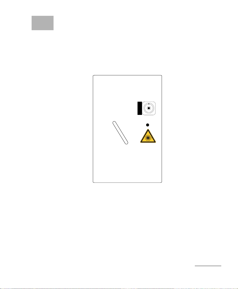
1 Introducing the FTB-2200
FTB-2200
BROADBAND SOURCE
OUT
ACTIVE
Broadband Source
The FTB-2200 Broadband Source is a polarization scrambled broadband
LED source covering the C + L bands. It is ideal for high-accuracy
polarization mode dispersion (PMD) measurement and has been
specifically designed to be used with EXFO’s FTB-5500B PMD Analyzer.
Typical Applications
This light source is suitable for high-accuracy PMD measurement, quality
control, calibration, acceptance testing and loss and return loss testing.
Broadband Source 1
Page 6
Introducing the FTB-2200 Broadband Source
Conventions
Conventions
Before using the product described in this guide, you should understand
the following conventions:
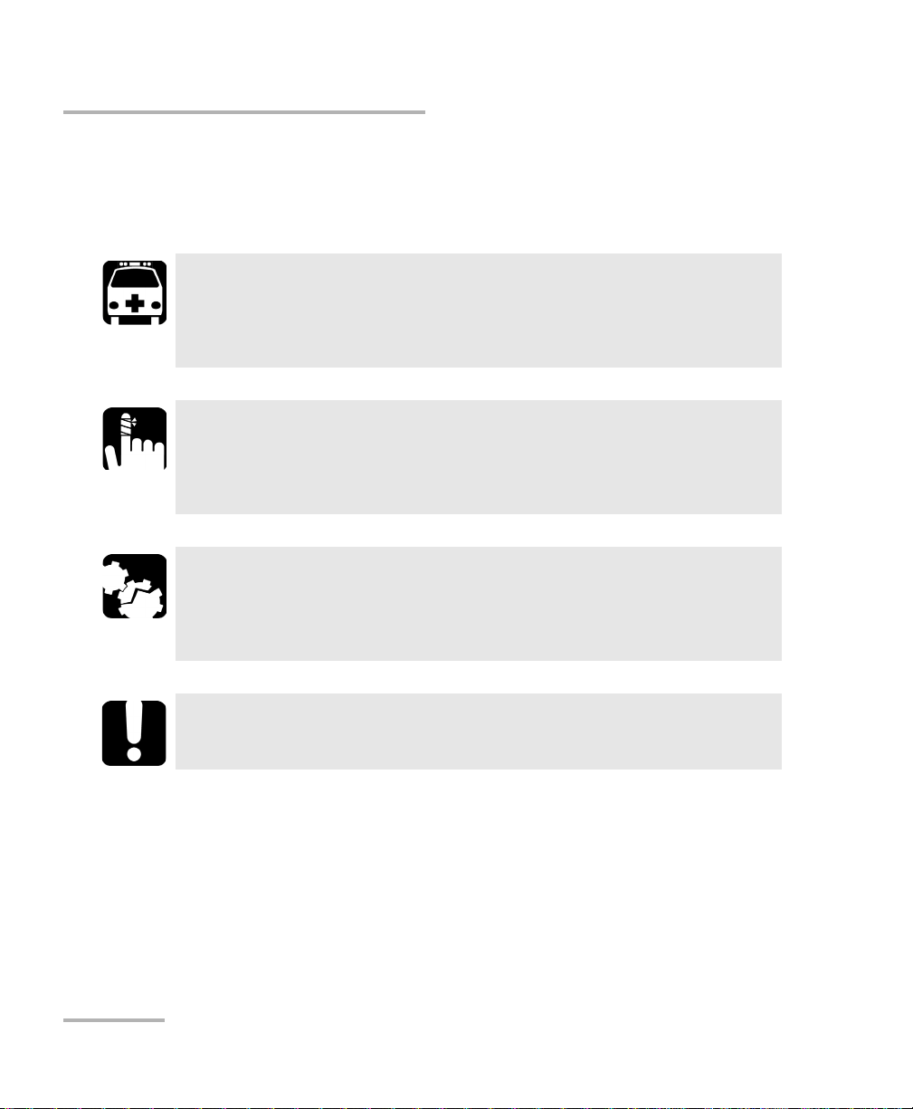
WARNING
Indicates a potentially hazardous situation which, if not avoided,
could result in death or serious injury. Do not proceed unless you
understand and meet the required conditions.
CAUTION
Indicates a potentially hazardous situation which, if not avoided,
may result in minor or moderate injury. Do not proceed unless you
understand and meet the required conditions.
CAUTION
Indicates a potentially hazardous situation which, if not avoided,
may result in component damage. Do not proceed unless you
understand and meet the required conditions.
IMPORTANT
Refers to information about this product you should not overlook.
For more information on equipment ratings, refer to the FTB-200 v2
Compact Modular Platform user guide
2 FTB-2200
Page 7
2 Safety Information
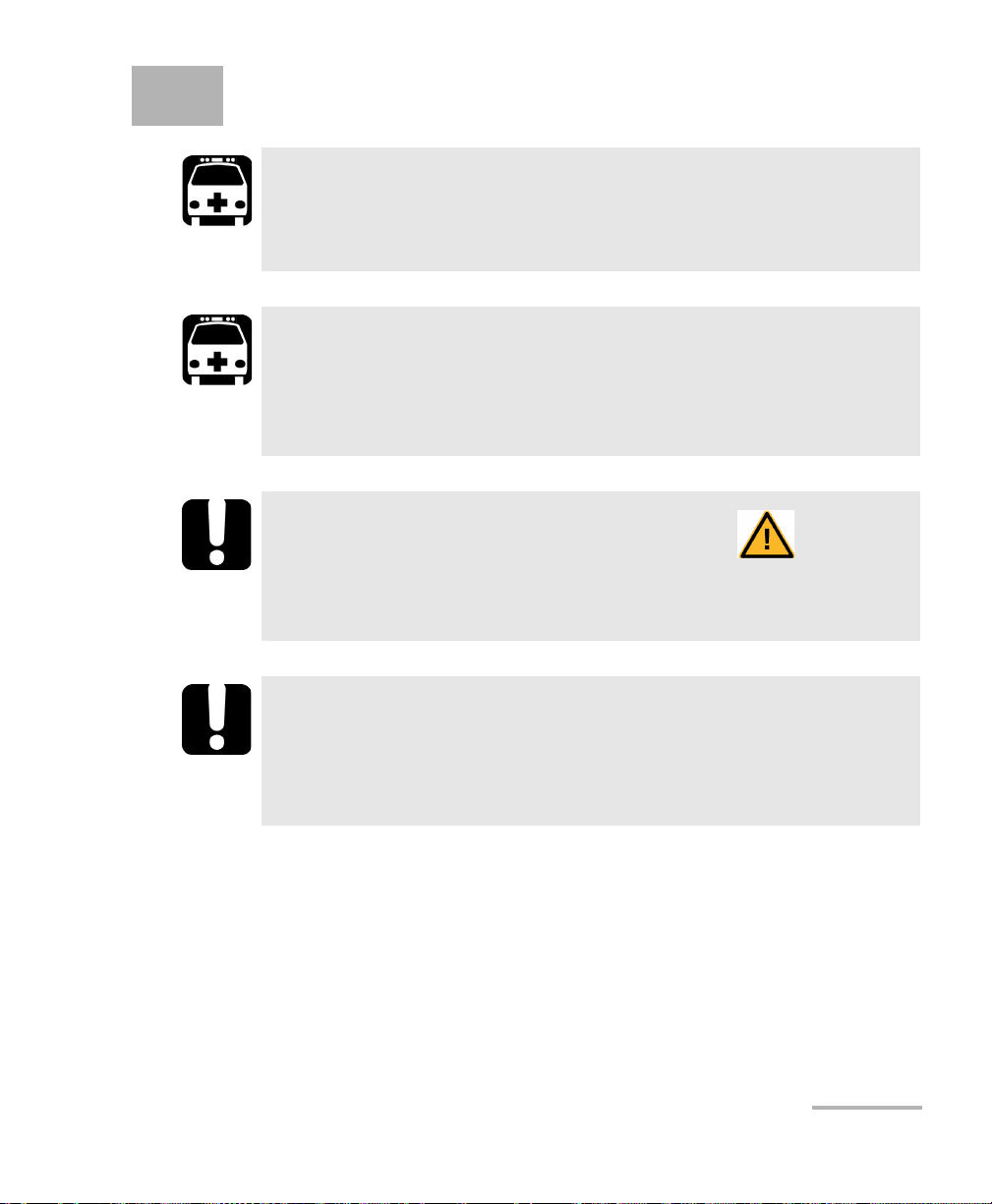
WARNING
Do not install or terminate fibers while a light source is active.
Never look directly into a live fiber and ensure that your eyes are
protected at all times.
WARNING
The use of controls, adjustments and procedures, namely for
operation and maintenance, other than those specified herein may
result in hazardous radiation exposure or impair the protection
provided by this unit.
IMPORTANT
When you see the following symbol on your unit , make sure
that you refer to the instructions provided in your user
documentation. Ensure that you understand and meet the required
conditions before using your product.
IMPORTANT
Other safety instructions relevant for your product are located
throughout this documentation, depending on the action to
perform. Make sure to read them carefully when they apply to your
situation.
Broadband Source 3
Page 8
Safety Information
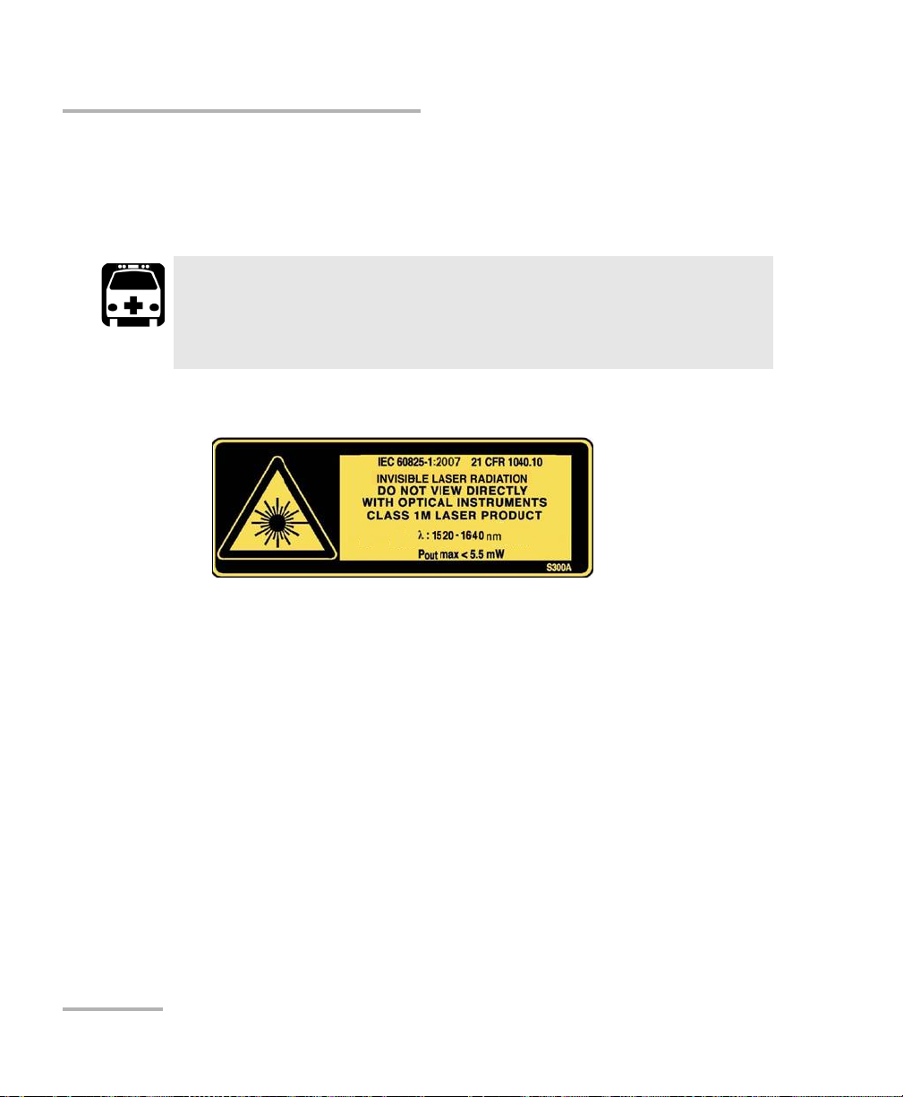
Your instrument is a Class 1M laser product in compliance with standards
IEC 60825-1: 2007 and 21 CFR 1040.10, except for deviations pursuant to
Laser Notice No. 50, dated June 24, 2007. Invisible laser radiation may be
encountered at the output port.
Viewing the laser output with certain optical instruments (for
example, eye loupes, magnifiers, and microscopes) within a
distance of 100 mm may pose an eye hazard.
The following label(s) indicate that the product contains a Class 1M source:
WARNING
4 FTB-2200
Page 9

3 Setting Up and Operating the
Broadband Source
Inserting and Removing Test Modules
CAUTION
Never insert or remove a module while the FTB-200 v2 Compact
Modular Platform is turned on. This will result in immediate and
irreparable damage to both the module and unit.
CAUTION
To avoid damaging your unit, use it only with modules approved by
EXFO.
WARNING
When the laser safety LED is flashing, at least one of your modules
is emitting an optical signal. Please check all modules, as it might
not be the one you are currently using.
Broadband Source 5
Page 10
Setting Up and Operating the Broadband Source
Inserting and Removing Test Modules
To insert a module into the FTB-200 v2 Compact Modular
Platform:
1. Turn off your unit.
2. Position the unit so that its front panel is facing you.
6 FTB-2200
Page 11
Setting Up and Operating the Broadband Source
Inserting and Removing Test Modules
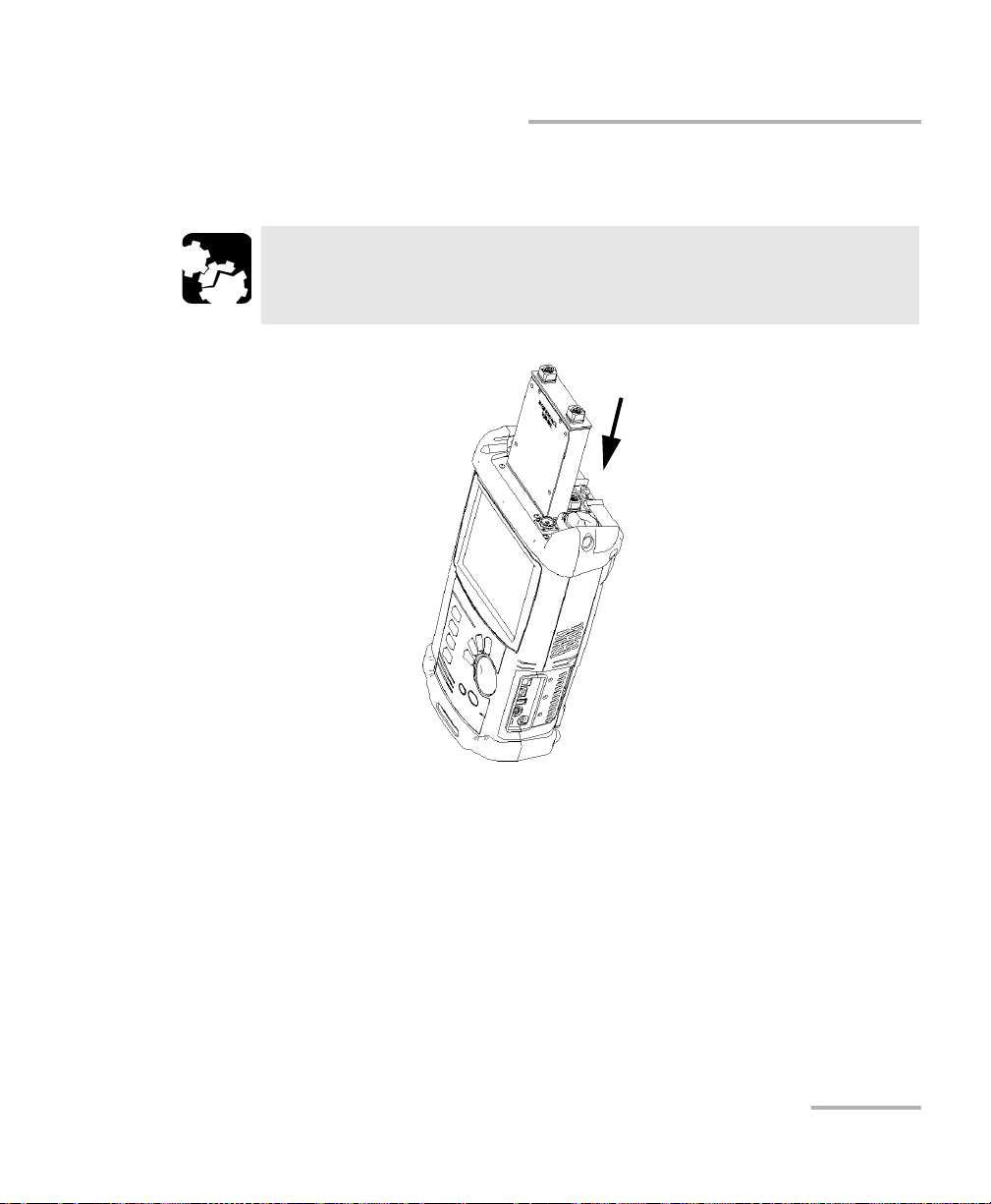
3. Take the module and place it vertically so that the retaining screw hole
is at the left of the connector pins.
CAUTION
Inserting a module upside down could result in permanent damage
to the module, as the connector pins might be bent.
4. Insert the protruding edges of the module into the grooves of the unit’s
module slot.
5. Push the module all the way to the bottom of the slot, until the
retaining screw makes contact with the unit casing.
6. Place the unit so that its bottom panel is facing you.
Broadband Source 7
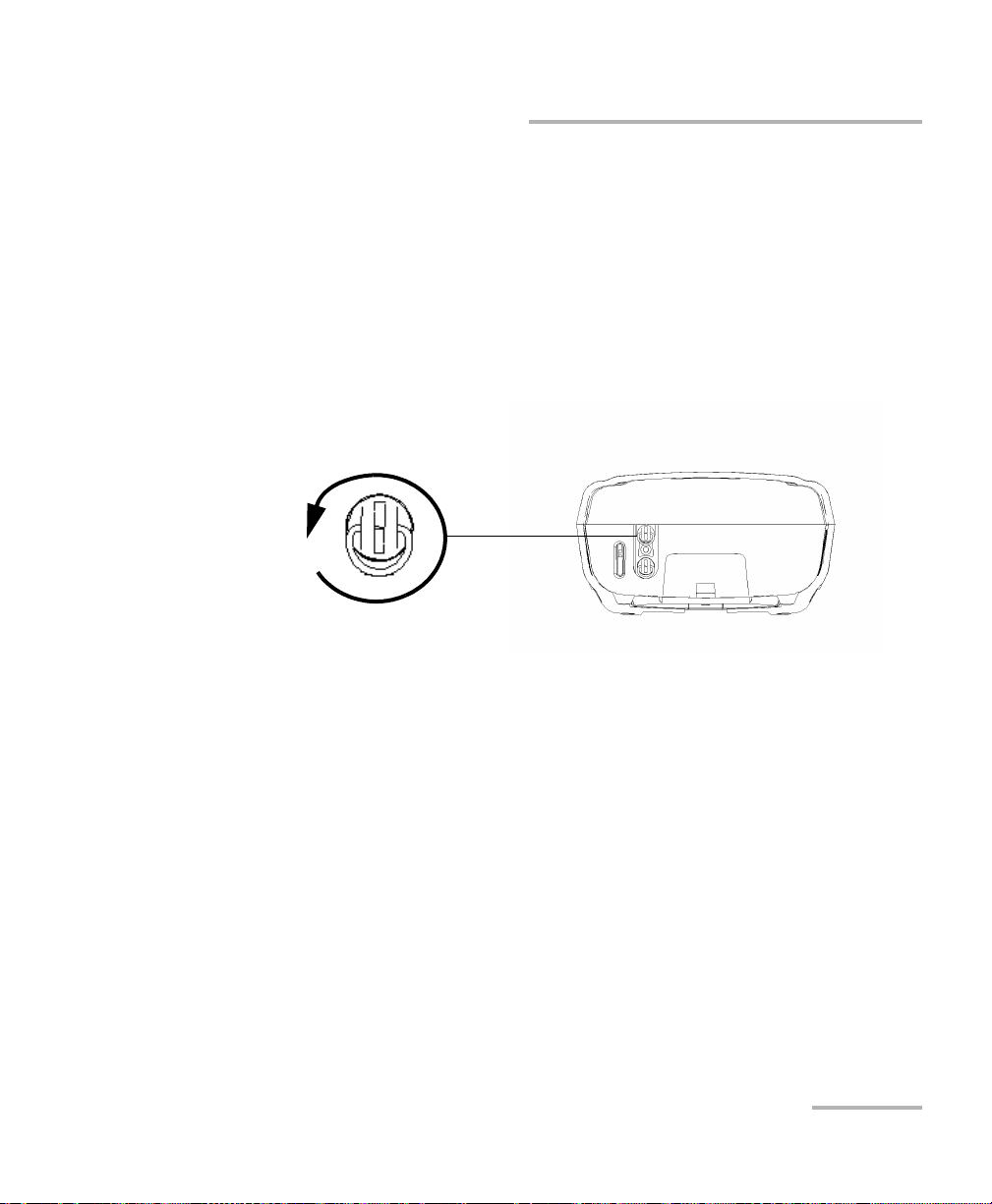
Page 12
Setting Up and Operating the Broadband Source
Turn retaining screws
clockwise
Bottom panel
Inserting and Removing Test Modules
7. While applying slight pressure to the module, lift the mobile part of the
retaining screw and use it to turn the retaining screw clockwise until it
is tightened.
This will secure the module into its “seated” position.
When you turn on the unit, the startup sequence will automatically detect
the module.
8 FTB-2200
Page 13
Setting Up and Operating the Broadband Source
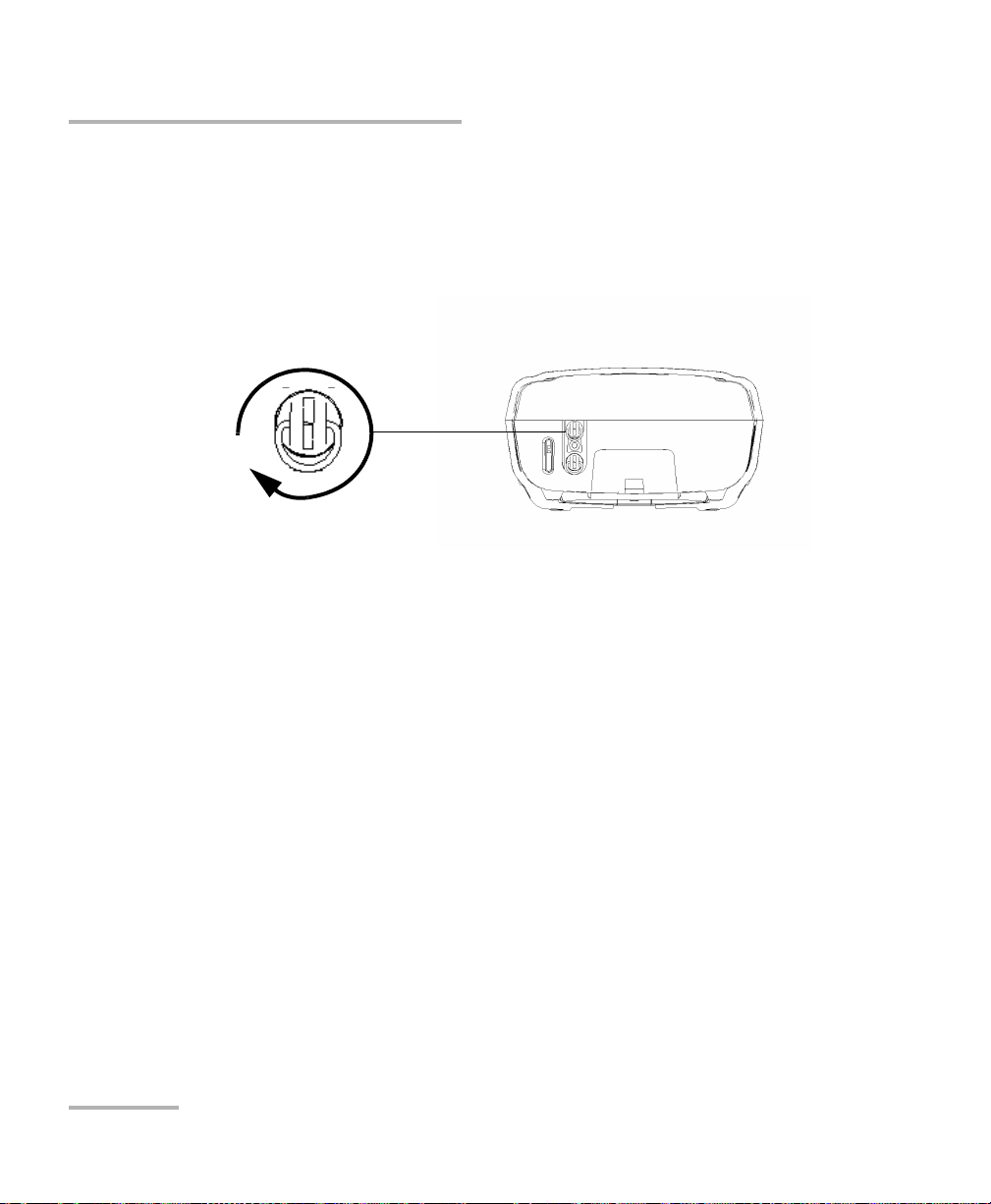
Turn retaining screws
counterclockwise
Bottom panel
Inserting and Removing Test Modules
To remove a module from the FTB-200 v2 Compact Modular
Platform:
1. Turn off your unit.
2. Position the unit so that the bottom panel is facing you.
3. Lift the mobile part of the retaining screw and use it to turn the
retaining screw counterclockwise until it stops.
The module will be slowly released from the slot.
4. Place the unit so that the top panel is facing you.
Broadband Source 9
Page 14

Setting Up and Operating the Broadband Source
Inserting and Removing Test Modules
5. Hold the module by its sides or by the handle (NOT by the connector)
and pull it out.
CAUTION
Pulling out a module by a connector could seriously damage both
the module and connector. Always pull out a module by its casing.
6. Cover empty slots with the supplied protective covers.
10 FTB-2200
Page 15

Setting Up and Operating the Broadband Source
Starting Module Applications
Starting Module Applications
Your modules can be configured and controlled from their dedicated
applications in Compact ToolBox.
To start a module application:
1. From Compact ToolBox, select the module to use.
It will turn blue to indicate that it is highlighted.
2. Under Applications, select an application, then press Start.
To start the Power Meter or Probe application:
From Main Menu, press Power Meter or Probe.
Broadband Source 11
Page 16

Setting Up and Operating the Broadband Source
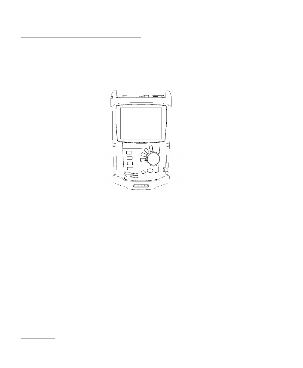
Display
pane
Control
Center
Function
Ta bs
Starting Module Applications
The main window (shown below) contains all the commands required to
control the Broadband Source:
12 FTB-2200
Page 17

Setting Up and Operating the Broadband Source
Cleaning and Connecting Optical Fibers
Cleaning and Connecting Optical Fibers
IMPORTANT
To ensure maximum power and to avoid erroneous readings:
Always inspect fiber ends and make sure that they are clean as
explained below before inserting them into the port. EXFO is
not responsible for damage or errors caused by bad fiber
cleaning or handling.
Ensure that your patchcord has appropriate connectors. Joining
mismatched connectors will damage the ferrules.
To connect the fiber-optic cable to the port:
1. Inspect the fiber using a fiber inspection microscope. If the fiber is
clean, proceed to connecting it to the port. If the fiber is dirty, clean it as
explained below.
2. Clean the fiber ends as follows:
2a. Gently wipe the fiber end with a lint-free swab dipped in isopropyl
alcohol.
2b. Use compressed air to dry completely.
2c. Visually inspect the fiber end to ensure its cleanliness.
Broadband Source 13
Page 18

Setting Up and Operating the Broadband Source
Cleaning and Connecting Optical Fibers
3. Carefully align the connector and port to prevent the fiber end from
touching the outside of the port or rubbing against other surfaces.
If your connector features a key, ensure that it is fully fitted into the
port’s corresponding notch.
4. Push the connector in so that the fiber-optic cable is firmly in place,
thus ensuring adequate contact.
If your connector features a screwsleeve, tighten the connector
enough to firmly maintain the fiber in place. Do not overtighten, as this
will damage the fiber and the port.
Note: If your fiber-optic cable is not properly aligned and/or connected, you will
notice heavy loss and reflection.
EXFO uses good quality connectors in compliance with EIA-455-21A
standards.
To keep connectors clean and in good condition, EXFO strongly
recommends inspecting them with a fiber inspection probe before
connecting them. Failure to do so will result in permanent damage to the
connectors and degradation in measurements.
14 FTB-2200
Page 19

Setting Up and Operating the Broadband Source
Bare metal
(or blue border)
indicates UPC
option
Green border
indicates APC
option
2 3 4
Installing the EXFO Universal Interface (EUI)
Installing the EXFO Universal Interface (EUI)
The EUI fixed baseplate is available for connectors with angled (APC) or
non-angled (UPC) polishing. A green border around the baseplate
indicates that it is for APC-type connectors.
To install an EUI connector adapter onto the EUI baseplate:
1. Hold the EUI connector adapter so the dust cap opens downwards.
2. Close the dust cap in order to hold the connector adapter more firmly.
3. Insert the connector adapter into the baseplate.
4. While pushing firmly, turn the connector adapter clockwise on the
baseplate to lock it in place.
Broadband Source 15
Page 20

Setting Up and Operating the Broadband Source
Activating or Deactivating Light Emission
Activating or Deactivating Light Emission
Before activating the source, read the Safety Information on page 3.
Note: You should let the source warm up for 30 minutes to obtain optimum
wavelength stability.
To activate or deactivate light emission:
Select ON to activate the light emission. The ACTIVE LED on the
module’s front panel lights up, indicating that the source is active. The
data display lights up and two red arrows appear beside the status
indicator on the data display, indicating that the source is on.
Select OFF to deactivate the light emission. The ACTIVE LED on the
module’s front panel turns off, indicating that the source is off. The
status indicator on the data display is dimmed and the two red arrows
disappear from the data display.
16 FTB-2200
Page 21

4 Maintenance
To help ensure long, trouble-free operation:
Always inspect fiber-optic connectors before using them and clean
them if necessary.
Keep the unit free of dust.
Clean the unit casing and front panel with a cloth slightly dampened
with water.
Store unit at room temperature in a clean and dry area. Keep the unit
out of direct sunlight.
Avoid high humidity or significant temperature fluctuations.
Avoid unnecessary shocks and vibrations.
If any liquids are spilled on or into the unit, turn off the power
immediately, disconnect from any external power source, remove the
batteries and let the unit dry completely.
The use of controls, adjustments and procedures, namely for
operation and maintenance, other than those specified herein may
result in hazardous radiation exposure or impair the protection
provided by this unit.
WARNING
Broadband Source 17
Page 22

Maintenance
Cleaning Fixed Connectors
Cleaning Fixed Connectors
Regular cleaning of connectors will help maintain optimum performance.
Do not try to disassemble the unit. Doing so would break the connector.
Looking into the optical connector while the light source is active
WILL result in permanent eye damage. EXFO strongly recommends
to TURN OFF the unit before proceeding with the cleaning
procedure.
To clean fixed connectors:
1. Fold a lint-free wiping cloth in four to form a square.
2. Moisten the center of the lint-free wiping cloth with only one drop of
isopropyl alcohol.
Alcohol may leave traces if used abundantly. Avoid contact between
the tip of the bottle and the wiping cloth, and do not use bottles
that distribute too much alcohol at a time.
WARNING
IMPORTANT
3. Gently wipe the connector threads three times with the folded and
moistened section of the wiping cloth.
IMPORTANT
Isopropyl alcohol takes approximately ten seconds to evaporate.
Since isopropyl alcohol is not absolutely pure, evaporation will
leave microscopic residue. Make sure you dry the surfaces before
evaporation occurs.
4. With a dry lint-free wiping cloth, gently wipe the same surfaces three
times with a rotating movement.
18 FTB-2200
Page 23

Maintenance
7
8
9
Cleaning Fixed Connectors
5. Throw out the wiping cloths after one use.
6. Moisten a cleaning tip (2.5 mm tip) with only one drop of isopropyl
alcohol.
IMPORTANT
Alcohol may leave traces if used abundantly. Avoid contact between
the tip of the bottle and the cleaning tip, and do not use bottles
that distribute too much alcohol at a time.
7. Slowly insert the cleaning tip into the connector until it reaches the
ferrule inside (a slow clockwise rotating movement may help).
8. Gently turn the cleaning tip one full turn.
9. Continue to turn as you withdraw the cleaning tip.
10. Repeat steps 7 to 9, but this time with a dry cleaning tip (2.5 mm tip
provided by EXFO).
Note: Make sure you don’t touch the soft end of the cleaning tip and verify the
cleanliness of the cotton tip.
11. Throw out the cleaning tips after one use.
Broadband Source 19
Page 24

Maintenance
Push
Tur n
Pull
Cleaning EUI Connectors
Cleaning EUI Connectors
Regular cleaning of EUI connectors will help maintain optimum
performance. There is no need to disassemble the unit.
If any damage occurs to internal connectors, the module casing will
have to be opened and a new calibration will be required.
Looking into the optical connector while the light source is active
WILL result in permanent eye damage. EXFO strongly recommends
to TURN OFF the unit before proceeding with the cleaning
procedure.
To clean EUI connectors:
1. Remove the EUI from the instrument to expose the connector
baseplate and ferrule.
IMPORTANT
WARNING
2. Moisten a 2.5 mm cleaning tip with one drop of isopropyl alcohol
(alcohol may leave traces if used abundantly).
3. Slowly insert the cleaning tip into the EUI adapter until it comes out on
the other side (a slow clockwise rotating movement may help).
20 FTB-2200
Page 25

Cleaning EUI Connectors
3
4
5
4. Gently turn the cleaning tip one full turn, then continue to turn as you
withdraw it.
5. Repeat steps 3 to 4 with a dry cleaning tip.
Note: Make sure you don’t touch the soft end of the cleaning tip.
6. Clean the ferrule in the connector port as follows:
6a. Deposit one drop of isopropyl alcohol on a lint-free wiping cloth.
IMPORTANT
Isopropyl alcohol may leave residues if used abundantly or left to
evaporate (about 10 seconds).
Maintenance
Avoid contact between the tip of the bottle and the wiping cloth,
and dry the surface quickly.
6b. Gently wipe the connector and ferrule.
6c. With a dry lint-free wiping cloth, gently wipe the same surfaces to
ensure that the connector and ferrule are perfectly dry.
6d. Verify connector surface with a portable fiber-optic microscope
(for example, EXFO’s FOMS) or fiber inspection probe (for
example, EXFO’s FIP).
7. Put the EUI back onto the instrument (push and turn clockwise).
8. Throw out cleaning tips and wiping cloths after one use.
Broadband Source 21
Page 26

Maintenance
Recalibrating the Unit
Recalibrating the Unit
EXFO manufacturing and service center calibrations are based on the
ISO/IEC 17025 standard (General Requirements for the Competence of
Testing and Calibration Laboratories). This standard states that calibration
documents must not contain a calibration interval and that the user is
responsible for determining the re-calibration date according to the actual
use of the instrument.
The validity of specifications depends on operating conditions. For
example, the calibration validity period can be longer or shorter depending
on the intensity of use, environmental conditions and unit maintenance, as
well as the specific requirements for your application. All of these elements
must be taken into consideration when determining the appropriate
calibration interval of this particular EXFO unit.
Under normal use, the recommended interval for your FTB-2200
Broadband Source is: one year.
For newly delivered units, EXFO has determined that the storage of this
product for up to six months between calibration and shipment does not
affect its performance (EXFO Policy PL-03).
22 FTB-2200
Page 27

Maintenance
Recycling and Disposal (Applies to European Union Only)
To help you with calibration follow-up, EXFO provides a special calibration
label that complies with the ISO/IEC 17025 standard and indicates the unit
calibration date and provides space to indicate the due date. Unless you
have already established a specific calibration interval based on your own
empirical data and requirements, EXFO would recommend that the next
calibration date be established according to the following equation:
Next calibration date = Date of first usage (if less than six months
after the calibration date) + Recommended calibration period (one
year)
To ensure that your unit conforms to the published specifications,
calibration may be carried out at an EXFO service center or, depending on
the product, at one of EXFO’s certified service centers. Calibrations at
EXFO are performed using standards traceable to national metrology
institutes.
Note: You may have purchased a FlexCare plan that covers calibrations. See the
Service and Repairs section of this user documentation for more
information on how to contact the service centers and to see if your plan
qualifies.
Recycling and Disposal
(Applies to European Union Only)
For complete recycling/disposal information as per European Directive
WEEE 2012/19/UE, visit the EXFO Web site at www.exfo.com/recycle.
Broadband Source 23
Page 28

Page 29

5 Troubleshooting
Solving Common Problems
Problem Possible Cause Solution
Source appears unstable. Insufficient
stabilization time.
Reflection
destabilizing the
source.
Ambient
temperature is
varying.
Wait a minimum
of 30 minutes for
optimum
stabilization.
Connect the
source using an
optical isolator.
Control ambient
temperature.
Broadband Source 25
Page 30

Troubleshooting
Obtaining Online Help
Obtaining Online Help
An online version of the FTB-2200 Broadband Source user guide is
conveniently available at all times from the application.
Note: You will also find a printable PDF version on your installation DVD.
To access online help:
Click the Help button on the function bar.
26 FTB-2200
Page 31

Troubleshooting
Contacting the Technical Support Group
Contacting the Technical Support Group
To obtain after-sales service or technical support for this product, contact
EXFO at one of the following numbers. The Technical Support Group is
available to take your calls from Monday to Friday, 8:00 a.m. to 7:00 p.m.
(Eastern Time in North America).
Technical Support Group
400 Godin Avenue
Quebec (Quebec) G1M 2K2
CANADA
For detailed information about technical support, and for a list of other
worldwide locations, visit the EXFO Web site at www.exfo.com.
If you have comments or suggestions about this user documentation, you
can send them to customer.feedback.manual@exfo.com.
To accelerate the process, please have information such as the name and
the serial number (see the product identification label), as well as a
description of your problem, close at hand.
1 866 683-0155 (USA and Canada)
Tel.: 1 418 683-5498
Fax: 1 418 683-9224
support@exfo.com
Broadband Source 27
Page 32

Troubleshooting
Transportation
You may also be requested to provide software and module version
numbers. This information, as well as technical support contact
information, can be found in the About function tab.
Select the Technical Support tab to view phone numbers and active
Select the Module Information tab to view the module identification,
Internet links to EXFO’s Technical Support Group. Use these links to
send an information request by e-mail or to access EXFO’s web site.
serial number and firmware version.
Transportation
Maintain a temperature range within specifications when transporting the
unit. Transportation damage can occur from improper handling. The
following steps are recommended to minimize the possibility of damage:
Pack the unit in its original packing material when shipping.
Avoid high humidity or large temperature fluctuations.
Keep the unit out of direct sunlight.
Avoid unnecessary shocks and vibrations.
28 FTB-2200
Page 33

6 Warranty
General Information
EXFO Inc. (EXFO) warrants this equipment against defects in material and
workmanship for a period of one year from the date of original shipment.
EXFO also warrants that this equipment will meet applicable specifications
under normal use.
During the warranty period, EXFO will, at its discretion, repair, replace,
or issue credit for any defective product, as well as verify and adjust the
product free of charge should the equipment need to be repaired or if the
original calibration is erroneous. If the equipment is sent back for
verification of calibration during the warranty period and found to meet all
published specifications, EXFO will charge standard calibration fees.
The warranty can become null and void if:
unit has been tampered with, repaired, or worked upon by
unauthorized individuals or non-EXFO personnel.
warranty sticker has been removed.
IMPORTANT
case screws, other than those specified in this guide, have been
removed.
case has been opened, other than as explained in this guide.
unit serial number has been altered, erased, or removed.
unit has been misused, neglected, or damaged by accident.
THIS WARRANTY IS IN LIEU OF ALL OTHER WARRANTIES EXPRESSED,
IMPLIED, OR STATUTORY, INCLUDING, BUT NOT LIMITED TO, THE
IMPLIED WARRANTIES OF MERCHANTABILITY AND FITNESS FOR A
PARTICULAR PURPOSE. IN NO EVENT SHALL EXFO BE LIABLE FOR
SPECIAL, INCIDENTAL, OR CONSEQUENTIAL DAMAGES.
Broadband Source 29
Page 34

Warranty
Liability
Liability
EXFO shall not be liable for damages resulting from the use of the product,
nor shall be responsible for any failure in the performance of other items to
which the product is connected or the operation of any system of which
the product may be a part.
EXFO shall not be liable for damages resulting from improper usage or
unauthorized modification of the product, its accompanying accessories
and software.
Exclusions
EXFO reserves the right to make changes in the design or construction of
any of its products at any time without incurring obligation to make any
changes whatsoever on units purchased. Accessories, including but not
limited to fuses, pilot lamps, batteries and universal interfaces (EUI) used
with EXFO products are not covered by this warranty.
This warranty excludes failure resulting from: improper use or installation,
normal wear and tear, accident, abuse, neglect, fire, water, lightning or
other acts of nature, causes external to the product or other factors beyond
the control of EXFO.
IMPORTANT
In the case of products equipped with optical connectors, EXFO will
charge a fee for replacing connectors that were damaged due to
misuse or bad cleaning.
Certification
EXFO certifies that this equipment met its published specifications at the
time of shipment from the factory.
30 FTB-2200
Page 35

Warranty
Service and Repairs
Service and Repairs
EXFO commits to providing product service and repair for five years
following the date of purchase.
To send any equipment for service or repair:
1. Call one of EXFO’s authorized service centers (see EXFO Service
Centers Worldwide on page 32). Support personnel will determine if
the equipment requires service, repair, or calibration.
2. If equipment must be returned to EXFO or an authorized service
center, support personnel will issue a Return Merchandise
Authorization (RMA) number and provide an address for return.
3. If possible, back up your data before sending the unit for repair.
4. Pack the equipment in its original shipping material. Be sure to include
a statement or report fully detailing the defect and the conditions under
which it was observed.
5. Return the equipment, prepaid, to the address given to you by support
personnel. Be sure to write the RMA number on the shipping slip. EXFO
will refuse and return any package that does not bear an RMA number.
Note: A test setup fee will apply to any returned unit that, after test, is found to
meet the applicable specifications.
After repair, the equipment will be returned with a repair report. If the
equipment is not under warranty, you will be invoiced for the cost
appearing on this report. EXFO will pay return-to-customer shipping costs
for equipment under warranty. Shipping insurance is at your expense.
Routine recalibration is not included in any of the warranty plans. Since
calibrations/verifications are not covered by the basic or extended
warranties, you may elect to purchase FlexCare Calibration/Verification
Packages for a definite period of time. Contact an authorized service center
(see EXFO Service Centers Worldwide on page 32).
Broadband Source 31
Page 36

Warranty
EXFO Service Centers Worldwide
EXFO Service Centers Worldwide
If your product requires servicing, contact your nearest authorized service
center.
EXFO Headquarters Service Center
400 Godin Avenue
Quebec (Quebec) G1M 2K2
CANADA
EXFO Europe Service Center
Winchester House, School Lane
Chandlers Ford, Hampshire S053 4DG
ENGLAND
EXFO Telecom Equipment
(Shenzhen) Ltd.
3rd Floor, Building 10,
Yu Sheng Industrial Park (Gu Shu
Crossing), No. 467,
National Highway 107,
Xixiang, Bao An District,
Shenzhen, China, 518126
1 866 683-0155 (USA and Canada)
Tel.: 1 418 683-5498
Fax: 1 418 683-9224
support@exfo.com
Tel.: +44 2380 246800
Fax: +44 2380 246801
support.europe@exfo.com
Tel: +86 (755) 2955 3100
Fax: +86 (755) 2955 3101
support.asia@exfo.com
32 FTB-2200
Page 37

Index
Index
A
About function tab ..................................... 28
activating source ......................................... 16
after-sales service ........................................ 27
application
contacting EXFO support from .............. 28
application, starting .................................... 11
C
caution
of personal hazard................................... 2
of product hazard.................................... 2
certification information ...............................iv
cleaning
EUI connectors....................................... 20
fiber ends .............................................. 13
fixed connectors .................................... 18
front panel............................................. 17
connectors, cleaning ............................. 18, 20
contact information, EXFO .......................... 28
conventions, safety ....................................... 2
customer service.................................... 28, 31
D
deactivating source ..................................... 16
detecting module.......................................... 8
E
equipment returns ...................................... 31
EUI
baseplate ............................................... 15
connector adapter ................................. 15
dust cap................................................. 15
EUI connectors, cleaning ............................. 20
EXFO support e-mail ................................... 28
EXFO universal interface. see EUI
EXFO Web site............................................. 28
F
fiber ends, cleaning ..................................... 13
firmware version, module............................ 28
front panel, cleaning ................................... 17
H
help. see online user guide
I
identification label....................................... 27
inserting a module ........................................ 5
L
label, identification...................................... 27
M
maintenance
EUI connectors....................................... 20
fixed connectors .................................... 18
front panel............................................. 17
general information ............................... 17
module
detection ................................................. 8
insertion................................................... 5
removal.................................................... 5
module information
firmware version number....................... 28
module identification number ...............28
serial number......................................... 28
mounting EUI connector adapter ................ 15
O
online user guide......................................... 26
Broadband Source 33
Page 38

Index
P
PDF. see online user guide
product
identification label................................. 27
R
removing a module ....................................... 5
return merchandise authorization (RMA) .... 31
S
safety
caution .................................................... 2
conventions ............................................. 2
warning ................................................... 2
serial number, module ................................ 28
service and repairs....................................... 31
service centers............................................. 32
shipping to EXFO ........................................ 31
software. see application
source
turning off............................................. 16
turning on ............................................. 16
storage requirements .................................. 17
symbols, safety.............................................. 2
W
warranty
certification............................................ 30
exclusions .............................................. 30
general................................................... 29
liability ................................................... 30
null and void.......................................... 29
T
technical support .................................. 27, 28
temperature for storage.............................. 17
transportation requirements ................. 17, 28
turning off source ....................................... 16
turning on source........................................ 16
U
user guide. see online user guide
34 FTB-2200
Page 39

NOTICE
抩⛙
CHINESE REGULATION ON RESTRICTION OF HAZARDOUS SUBSTANCES
₼⦌␂ℝ☀⹂䓸德棟Ⓟ䤓屓⸩
NAMES AND CONTENTS OF THE TOXIC OR HAZARDOUS SUBSTANCES OR ELEMENTS
CONTAINED IN THIS EXFO PRODUCT
▔⚺⦷㦻 EXFO ℶ❐₼䤓㦘㹡㦘⹂䓸德㒥⏒侯䤓⚜䱿✛⚺摞
O
Indicates that this toxic or hazardous substance contained in all of the homogeneous
materials for this part is below the limit requirement in SJ/T11363-2006
嫷䯉年㦘㹡㦘⹂䓸德⦷年捷ↅ㓏㦘⧖德㧟㠨₼䤓⚺摞⧖⦷ SJ/T11363-2006 㪖屓⸩䤓
棟摞尐㻑ⅴₚᇭ
X
Indicates that this toxic or hazardous substance contained in at least one of the homogeneous
materials used for this part is above the limit requirement in SJ/T11363-2006
嫷䯉年㦘㹡㦘⹂䓸德咂⺠⦷年捷ↅ䤓㩟⧖德㧟㠨₼䤓⚺摞怔⒉ SJ/T11363-2006 㪖
屓⸩䤓棟摞尐㻑ᇭ
Part Name
捷ↅ⚜䱿
Toxic or hazardous Substances and Elements
㦘㹡㦘⹂䓸德✛⏒侯
Lead
杔
(Pb)
Mercury
㻭
(Hg)
Cadmium
椣
(Cd)
Hexavalent
Chromium
⏼ↆ杻
(Cr VI)
Pol yb ro mi na te d
biphenyls
⮩䅃勣啾
(PBB)
Polybrominated
diphenyl ethers
⮩䅃ℛ啾搩
(PBDE)
Enclosure
⮥⮂
OO O O O O
Electronic and
electrical
sub-assembly
䟄✛䟄兓ↅ
XO X O X X
Optical
sub-assembly
a
⏘ⷵ兓ↅ
a
a. If applicable.
Ⱁ㨫抑䞷ᇭ
XO O O O O
Mechanical
sub-assembly
a
㧉㬿兓ↅ
a
OO O O O O
Page 40

MARKING REQUIREMENTS
㪖㽷尐㻑
Product
ℶ❐
Environmental protection use period (years)
䘾⬒≬㔳∎䞷㦮棟 ( )
Logo
㪖㉦
This Exfo product
㦻 EXFO ℶ❐
10
Battery
a
䟄㻯
a
a. If applicable.
Ⱁ㨫抑䞷ᇭ
5
Page 41

P/N: 1064485
www.EXFO.com · info@exfo.com
CORPORATE HEADQUARTERS 400 Godin Avenue Quebec (Quebec) G1M 2K2 CANADA
Tel.: 1 418 683-0211 · Fax: 1 418 683-2170
EXFO AMERICA 3400 Waterview Parkway Suite 100 Richardson, TX 75080 USA
EXFO EUROPE Winchester House,
EXFO ASIA-PACIFIC 100 Beach Road,
EXFO CHINA Beijing Global Trade Center, Tower C,
EXFO SERVICE ASSURANCE 270 Billerica Road Chelmsford MA, 01824 USA
EXFO FINLAND Elektroniikkatie 2 FI-90590 Oulu, FINLAND
TOLL-FREE (USA and Canada) 1 800 663-3936
© 2014 EXFO Inc. All rights reserved.
Printed in Canada (2014-01)
School Lane
#25-01/03 Shaw Tower
Room 1207, 36 North Third Ring Road
East, Dongcheng District
Tel.: 1 972-761-927 · Fax: 1 972-761-9067
Chandlers Ford, Hampshire S053 4DG ENGLAND
Tel.: +44 2380 246 800 · Fax: +44 2380 246 801
SINGAPORE 189702
Tel.: +6563338241 · Fax: +6563338242
Beijing 100013 P. R. CHINA
Tel.: +86 (10) 5825 7755 · Fax: +86 (10) 5825 7722
Tel.: 1 978 367-5600 · Fax: 1 978 367-5700
Tel.: +358 (0) 403 010 300 · Fax: +358 (0) 8 564 5203
 Loading...