

Page 1
FIP-400B
Fiber Inspection Probe and ConnectorMax2
User Guide
Page 2

Copyright © 2013–2014 EXFO Inc. All rights reserved. No part of this
publication may be reproduced, stored in a retrieval system or transmitted
in any form, be it electronically, mechanically, or by any other means such
as photocopying, recording or otherwise, without the prior written
permission of EXFO Inc. (EXFO).
Information provided by EXFO is believed to be accurate and reliable.
However, no responsibility is assumed by EXFO for its use nor for any
infringements of patents or other rights of third parties that may result from
its use. No license is granted by implication or otherwise under any patent
rights of EXFO.
EXFO’s Commerce And Government Entities (CAGE) code under the North
Atlantic Treaty Organization (NATO) is 0L8C3.
The information contained in this publication is subject to change without
notice.
Trademarks
EXFO’s trademarks have been identified as such. However, the presence
or absence of such identification does not affect the legal status of any
trademark.
Units of Measurement
Units of measurement in this publication conform to SI standards and
practices.
Patents
The design patent is pending for this product.
Version number: 5.0.2
ii FIP-400B
Page 3

Contents
Certification Information ........................................................................................................v
1 Introducing the FIP-400B Fiber Inspection Probe and ConnectorMax2 .... 1
Probe ......................................................................................................................................1
Available Models ....................................................................................................................2
Probe Tips ...............................................................................................................................3
LED Indicator ..........................................................................................................................4
ConnectorMax2 Software .......................................................................................................5
Conventions ............................................................................................................................6
2 Safety Information ....................................................................................... 7
3 Setting up Your Fiber Inspection Probe and ConnectorMax2 ................... 9
Changing the Fiber Inspection Probe Tip ................................................................................9
Adjusting Brightness .............................................................................................................10
Setting up Autonaming ........................................................................................................12
Managing and Selecting Test Configurations ........................................................................20
Editing the Power Meter Test Configurations ........................................................................40
Reverting to Factory Settings ................................................................................................42
Changing Fiber Information of Existing Captures .................................................................43
4 Inspecting Fiber Ends ................................................................................. 45
Inspecting Fiber Ends (Single Fiber and Transceiver - Fiber Receptacles) ...............................45
Setting Up Multifiber Inspection ...........................................................................................49
Displaying Multifiber Connector Overlay ..............................................................................50
Inspecting Fiber Ends (Multifiber) .........................................................................................51
Retesting a Fiber (Multifiber) ................................................................................................58
Saving Files ...........................................................................................................................60
Opening and Closing Files ....................................................................................................63
Analyzing Captures ...............................................................................................................64
Displaying or Hiding the Power Meter and VFL Controls .......................................................69
Clearing Power Meter Measurements Automatically .............................................................70
Measuring Power or Insertion Loss .......................................................................................71
Viewing Power Meter Results ...............................................................................................72
Identifying Fiber Faults Visually with the VFL ........................................................................73
Creating Reports ...................................................................................................................74
Updating the Firmware and Software ...................................................................................77
Fiber Inspection Probe iii
Page 4

5 Maintenance ................................................................................................81
General Maintenance ............................................................................................................81
Recycling and Disposal (Applies to European Union Only) ....................................................81
6 Troubleshooting ..........................................................................................83
Solving Common Problems ...................................................................................................83
Contacting the Technical Support Group ..............................................................................86
Viewing Information about ConnectorMax2 ........................................................................87
Viewing Online Help .............................................................................................................87
Transportation ......................................................................................................................87
7 Warranty ......................................................................................................89
General Information .............................................................................................................89
Liability .................................................................................................................................90
Exclusions .............................................................................................................................90
Certification ..........................................................................................................................90
Service and Repairs ...............................................................................................................91
EXFO Service Centers Worldwide ..........................................................................................92
A Technical Specifications ..............................................................................93
B Fiber Inspection Probe Tip Compatibility Chart .......................................95
Index .................................................................................................................99
iv FIP-400B
Page 5

Certification Information
Certification Information
North America Regulatory Statement
This unit was certified by an agency approved in both Canada and the
United States of America. It has been evaluated according to applicable
North American approved standards for product safety for use in Canada
and the United States.
Electronic test and measurement equipment is exempt from FCC part 15,
subpart B compliance in the United States of America and from ICES-003
compliance in Canada. However, EXFO Inc. makes reasonable efforts to
ensure compliance to the applicable standards.
The limits set by these standards are designed to provide reasonable
protection against harmful interference when the equipment is operated in
a commercial environment. This equipment generates, uses, and can
radiate radio frequency energy and, if not installed and used in accordance
with the user guide, may cause harmful interference to radio
communications. Operation of this equipment in a residential area is likely
to cause harmful interference in which case the user will be required to
correct the interference at his own expense.
Modifications not expressly approved by the manufacturer could void the
user's authority to operate the equipment.
European Community Declaration of Conformity
An electronic version of the declaration of conformity for your product is
available on our website at www.exfo.com. Refer to the product’s page on
the Web site for details.
Fiber Inspection Probe v
Page 6

Page 7
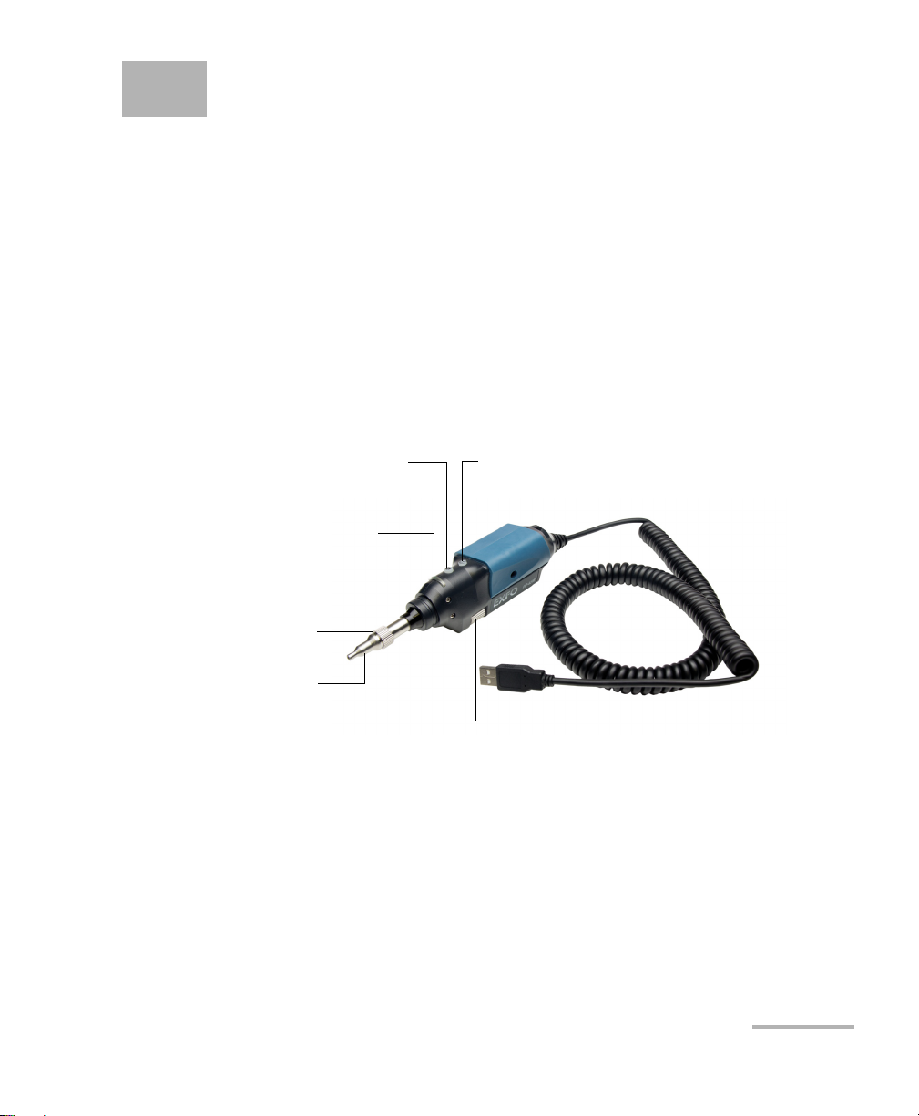
1 Introducing the FIP-400B Fiber
Status LED
Retaining nut
Focus
Magnification control
Capture control
Interchangeable
adapter tips
Inspection Probe and
ConnectorMax2
The FIP-400B Fiber Inspection Probe is a portable video microscope used
to inspect fiber ends. Unlike traditional microscopes, the FIP-400B
facilitates the examination of patchcord connectors and also hard-to-reach
connectors on the back of patch panels and bulkhead adapters.
Probe
The FIP-400B is designed to be an intuitive, easy-to-use piece of
equipment. This video microscope is used for inspecting fiber ends.
The focus knob can be turned in either direction to focus the image.
Fiber Inspection Probe 1
The magnification control button allows you to shift between three
levels of magnification. When pressed for one second, it activates the
auto focus.
The capture control button allows you to capture an image, perform an
analysis, or return to the Live video mode.
Page 8
Introducing the FIP-400B Fiber Inspection Probe and ConnectorMax2
Available Models
The retaining nut holds tips securely in place, ensuring they are always
fastened in the correct position.
The status LED gives you information about the probe or the analysis
results.
The interchangeable adapter tips give you the possibility to use various
tips depending on the type of connector you are inspecting.
The probe comes equipped with a protective cap that fits over basic tips;
therefore, you do not need to remove the tip before putting the cap on.
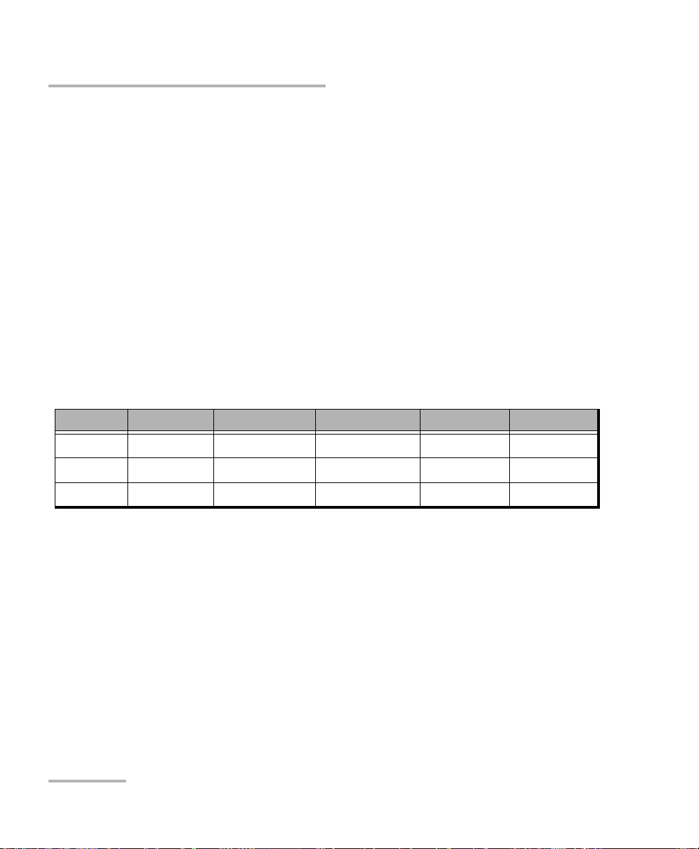
Available Models
The features available for your probe are automatically detected when you
connect it to your unit. The table below shows which feature is available
for each model.
Models Inspection Auto analysis Auto centering Auto focus Auto capture
FIP-410B X - - - -
FIP-420B X X X - -
FIP-430B X X X X X
Note: The auto capture is not available in multifiber mode.
Note: When the internal temperature of the FIP-430B is too low, the probe
performs a warm-up that can last up to a minute.
2 FIP-400B
Page 9

Introducing the FIP-400B Fiber Inspection Probe and ConnectorMax2
Probe Tips
Probe Tips
The FIP-400B comes with two interchangeable tips included in two
different packages (UPC or APC). Additional models are also available.
UPC package:
FIPT-400-FC-SC: FC-SC Bulkhead tip
FIPT-400-U25M: Universal patchcord tip (2.5 mm ferrule)
APC package:
FIPT-400-SC-APC: SC APC tip for bulkhead adapter
FIPT-400-U25MA: Universal patchcord tip for 2.5 mm ferrules
Other tip models are available for various bulkhead adapters and
patchcord connectors. For more information about tips and their use, see
the Fiber Inspection Probe Tip Compatibility Chart on page 95, or visit the
EXFO Web site.
Fiber Inspection Probe 3
Page 10
Introducing the FIP-400B Fiber Inspection Probe and ConnectorMax2
LED Indicator
LED Indicator
The LED located on the probe gives you information about the probe or the
analysis results.
LED Status
Flashing blue Detection of the probe in progress
Analysis in progress
Waiting mode. The auto focus
process starts automatically when
you insert an optical fiber
connector (FIP-430B only)
Auto focus in progress (FIP-430B
only)
Probe is initializing
Flashing red There is a major problem preventing
the probe from functioning properly
Blue
Probe detected and ready
On a computer, the USB port is in
suspend mode
Red In Capture mode, current FIP result
status is Fail (FIP-420B and FIP-430B)
Green In Capture mode, current FIP result
status is Pass (FIP-420B and FIP-430B)
4 FIP-400B
Page 11
Introducing the FIP-400B Fiber Inspection Probe and ConnectorMax2
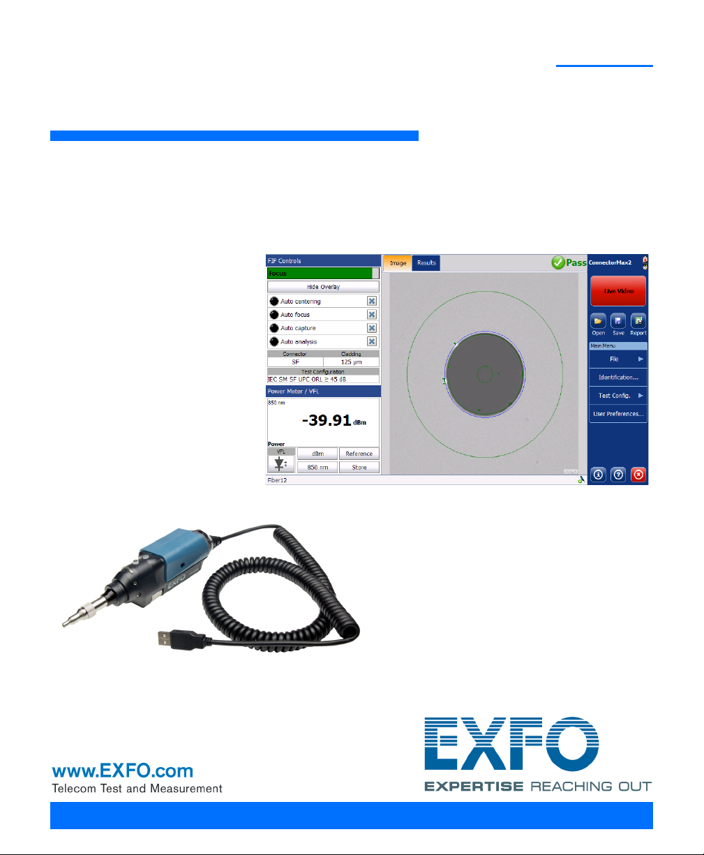
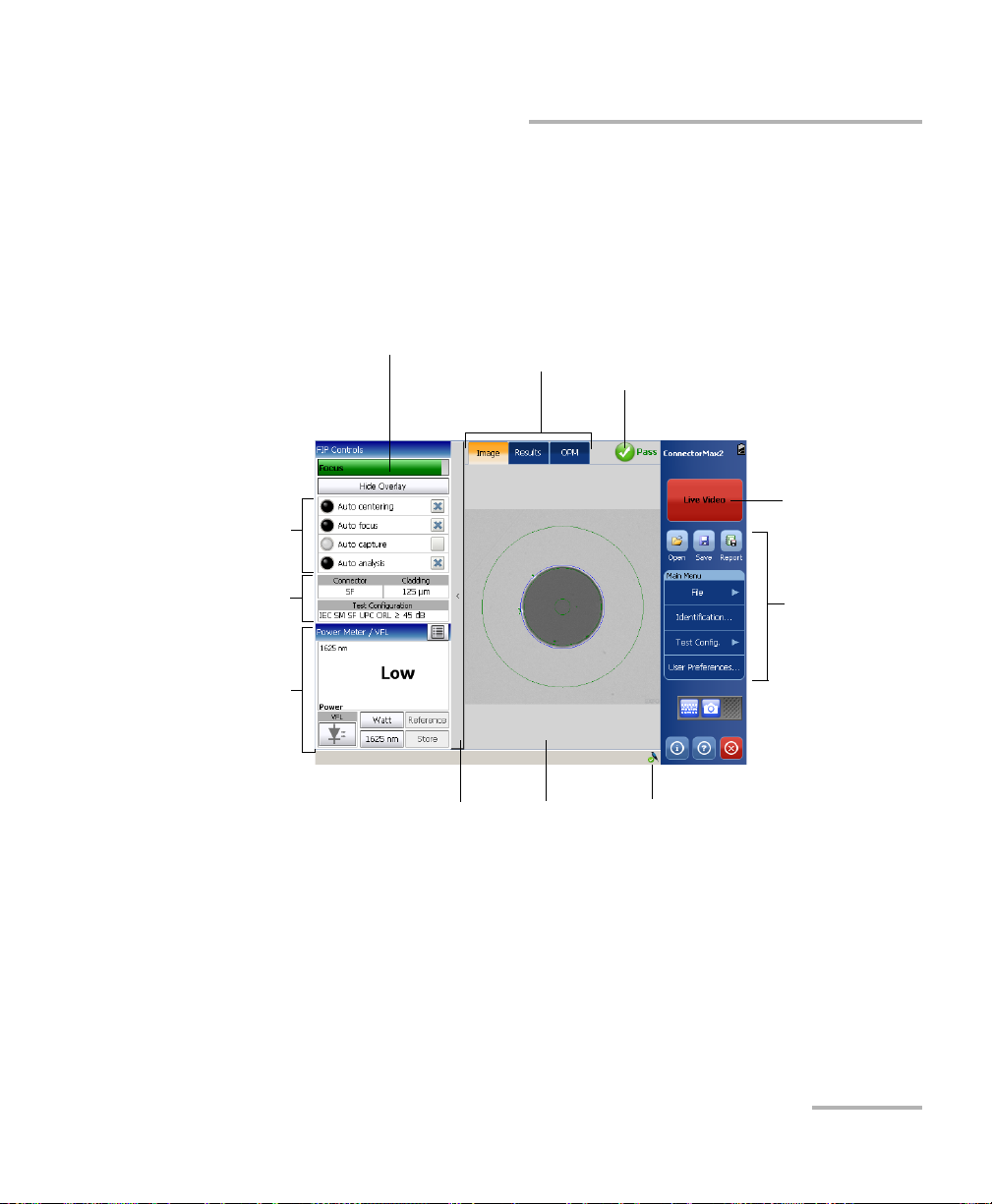
Button bar
Viewing
area
Probe connection
status
Image, Results, and
Power Meter tabs
Capture/Live
mode
button
Focus indicator Global status
(Power meter and current connector
(SF) or all fibers (MF))
Te st
configuration
Shows or hides the FIP
control panel (FTB-200v2
only)
Power meter
controls and
results/VFL
Features
ConnectorMax2 Software
ConnectorMax2 Software
ConnectorMax2 is the application used to view the fiber inspections. You
can also use specific test configurations and analyze the fibers
automatically upon capturing a picture. This application is available on the
MAX-FIP Viewer.
Fiber Inspection Probe 5
Page 12

Introducing the FIP-400B Fiber Inspection Probe and ConnectorMax2
Conventions
Conventions
Before using the product described in this guide, you should understand
the following conventions:
WARNING
Indicates a potentially hazardous situation which, if not avoided,
could result in death or serious injury. Do not proceed unless you
understand and meet the required conditions.
CAUTION
Indicates a potentially hazardous situation which, if not avoided,
may result in minor or moderate injury. Do not proceed unless you
understand and meet the required conditions.
CAUTION
Indicates a potentially hazardous situation which, if not avoided,
may result in component damage. Do not proceed unless you
understand and meet the required conditions.
IMPORTANT
Refers to information about this product you should not overlook.
Note: The appearance of the application may vary for other operating systems
and units.
Note: In this documentation, the words “tap” and “double-tap” (related to the
use of a touchscreen) replace the words “click” and “double-click”.
6 FIP-400B
Page 13
2 Safety Information
WARNING
Do not install or terminate fibers while a light source is active.
Never look directly into a live fiber and ensure that your eyes are
protected at all times.
WARNING
The use of controls, adjustments and procedures, namely for
operation and maintenance, other than those specified herein may
result in hazardous radiation exposure or impair the protection
provided by this unit.
IMPORTANT
When you see the following symbol on your unit , make sure
that you refer to the instructions provided in your user
documentation. Ensure that you understand and meet the required
conditions before using your product.
IMPORTANT
Other safety instructions relevant for your product are located
throughout this documentation, depending on the action to
perform. Make sure to read them carefully when they apply to your
situation.
CAUTION
Do not use the fiber probe outdoors in wet locations.
Fiber Inspection Probe 7
Page 14
Safety Information
Equipment Ratings
Tem pe ra tu re
Operation
Storage
-10 °C to 50 °C (14 °F to 122 °F)
-40 °C to 70 °C (-40 °F to 158 °F)
Relative humidity 0 % to 95 % non-condensing
Maximum operation
2000 m (6562 ft)
altitude
Pollution degree 3
a
Overvoltage category I
a. Equipment should be normally protected against exposure to direct sunlight, precipitations and full wind
pressure.
8 FIP-400B
Page 15
3 Setting up Your Fiber
Inspection Probe and
ConnectorMax2
You can change various settings in ConnectorMax2 such as the default
storage location or the automated file name. These settings are stored for
each user and kept for future work sessions.
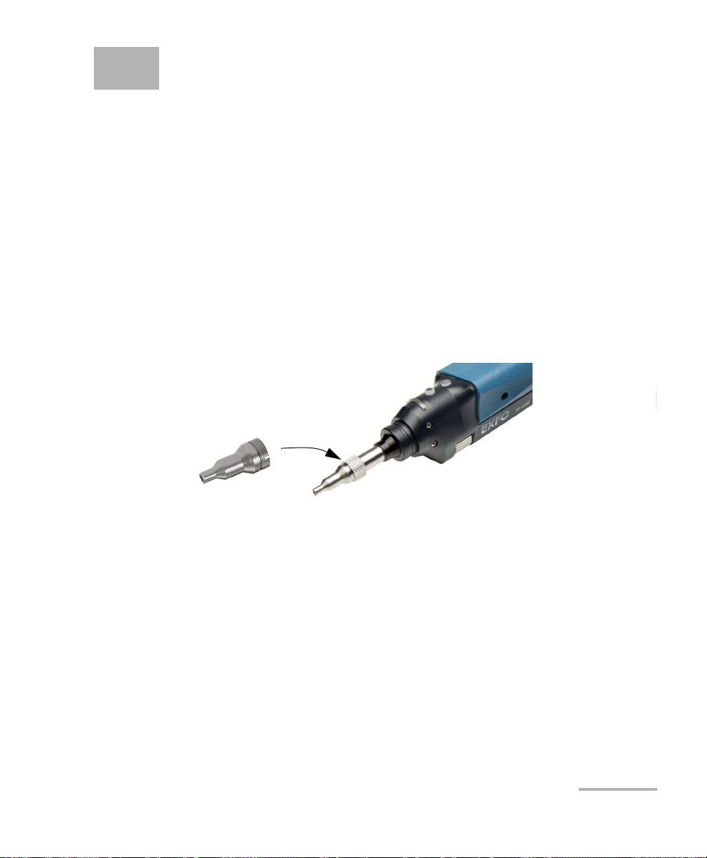
Changing the Fiber Inspection Probe Tip
You can use various tips depending on the type of connector you are
inspecting. For more information about tips you can use, see the Fiber
Inspection Probe Tip Compatibility Chart on page 95, or contact your
vendor for additional information.
To change a tip:
1. Untighten the tip’s retaining nut.
2. Remove the tip.
3. Insert a new tip.
4. Adjust the tip to the notch.
5. Retighten the retaining nut.
Fiber Inspection Probe 9
Page 16
Setting up Your Fiber Inspection Probe and ConnectorMax2
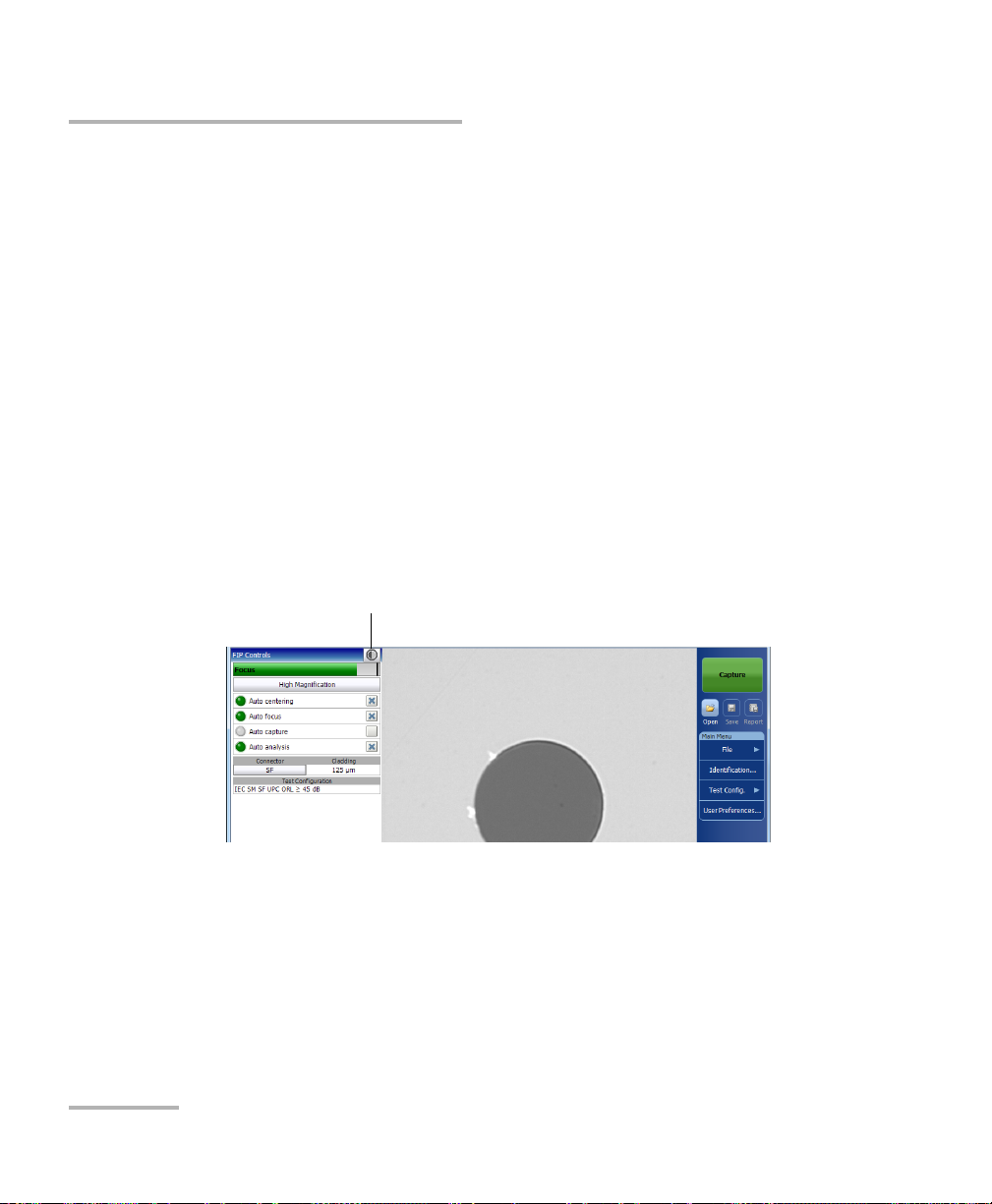
Brightness button
Adjusting Brightness
Adjusting Brightness
Once the probe is connected to a fiber, you can adjust brightness in order
to better view the fiber under inspection.
The default brightness value is 50 %. This corresponds to the automatic
brightness mode. The brightness automatically returns to 50 %:
when you exit the application and the probe is still connected
when the application is open and you plug and unplug the probe
when the platform is in suspend or resume mode
when you lock or unlock a session (except on a MAX-700B)
when you log in or log out of a session (except on a MAX-700B)
To adjust brightness:
1. In Live video mode, tap the button to switch to video settings mode.
10 FIP-400B
Page 17
Setting up Your Fiber Inspection Probe and ConnectorMax2
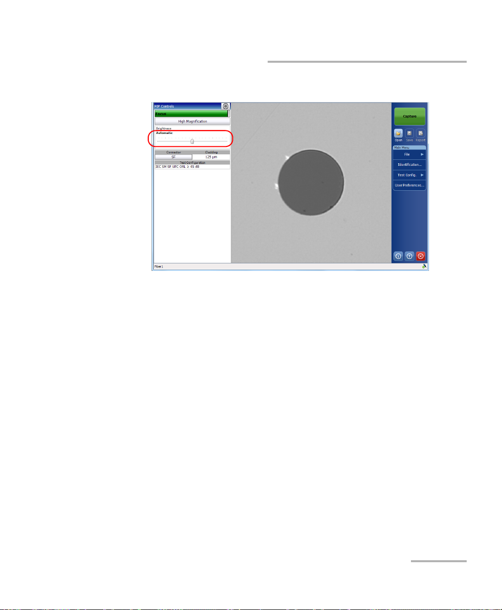
Adjusting Brightness
2. Use the brightness slider to set the levels to suit your needs.
Note: The application returns to the FIP controls default mode after 10 seconds of
inactivity.
Note: To optimize the analysis of the connector, EXFO recommends to set the
brightness to Auto most of the time.
When the brightness level is different than 50 %, the Automatic button
appears. Tapping on the Automatic button resets the brightness value to
50 %. The Automatic button disappears when the brightness level equals
50 %.
Fiber Inspection Probe 11
Page 18
Setting up Your Fiber Inspection Probe and ConnectorMax2
Setting up Autonaming
Setting up Autonaming
The autonaming feature is useful to make a relevant naming scheme for
your tests. This also ensures that you do not overwrite files by mistake. You
can select which item goes in the file name (appears at the bottom of the
window), as well as the type of separator you want to use in between.
A preview is available to show you the final output of the file name.
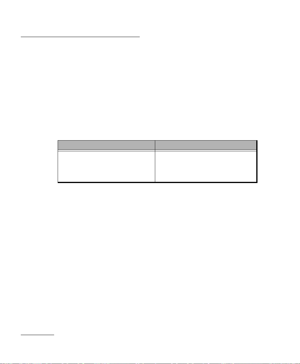
The file name is made of one or more static parts (alphanumeric) and one
or more variable parts (numeric) that will be incremented or
decremented, according to your selection, as follows:
If you choose incrementation... If you choose decrementation...
Variable part increases until it
reaches the highest possible value
with the selected number of digits,
then restarts at 1.
Note: To decrement values, the start number must be higher than the stop
number.
The file name can be incremented using one or more identifiers. Selecting
a single identifier will follow the incrementation (or decrementation) value
you have set.
For single fibers (SF or Transceivers), when selecting more than one
identifier, the latter appear sequentially in the order that you have set, and
the incrementation will start with the last item in the list (the one with the
farthest indentation). For example, if you have a file name with the
Location, Cable and Fiber identifiers, in that order, the first item to be
incremented is the Fiber identifier, then Cable, then Location:
Location 1, Cable 1, Fiber 1
Location 1, Cable 1, Fiber 2
Variable part decreases until it
reaches 1, then restarts at the highest
possible value with the selected
number of digits.
12 FIP-400B
Page 19

Setting up Your Fiber Inspection Probe and ConnectorMax2
Setting up Autonaming
Location 1, Cable 2, Fiber 1
Location 1, Cable 2, Fiber 2
and so forth.
For multifibers, when several identifiers for the filename are selected, they
appear sequentially in the order you have set. However, only one
increment can be used to create a multifiber set of captures. If several
increments are selected, only the most indented identifier will be used as
the increment. If no auto increment is defined, the identifier Frame is used
(whether or not it is selected for the file name).
After a result is saved, you have to return to the Live video mode so that the
application prepares the next file name by incrementing (or decrementing)
the suffix.
Note: If you choose not to save a particular file, the suggested file name remains
available for the next capture. This applies to all type of connectors.
If you deactivate the automatic file naming function, the application
displays a Save As window and no default file name is suggested.
The autonaming parameters can be set only for files that have not been
saved yet. You will only see the parameters for the current and next capture
(when the test is done but not saved yet), or for the next capture only (test
is not done yet). Otherwise, the parameters will not be displayed.
It is also possible to revert the settings to their default values.
Fiber Inspection Probe 13
Page 20

Setting up Your Fiber Inspection Probe and ConnectorMax2
Setting up Autonaming
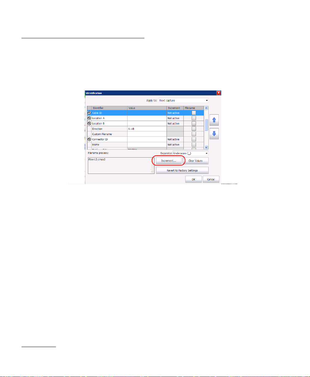
To configure the automatic file naming:
1. From the Main Menu, tap Identification.
2. From the Apply to list, ensure that Next capture or Current and Next
capture is selected.
14 FIP-400B
Page 21

Setting up Your Fiber Inspection Probe and ConnectorMax2
Setting up Autonaming
3. Enter all the information as follows:
3a. Locate the row corresponding to the identifier that you want to
modify.
If an identifier is marked with an icon, a predefined list with
choices is available. If you select None, it disables the field from
the list (Next capture and Current and Next capture).
Note: When in Current capture, the identifiers set to None disappear from the list.
Note: The identifiers marked with an icon are fields that can be customized and
edited. The name of the identifier and its value can be modified.
3b. Tap t h e Value column corresponding to the desired identifier.
3c. Enter the information.
Note: You cannot edit the information in the dark gray boxes.
Fiber Inspection Probe 15
Page 22
Setting up Your Fiber Inspection Probe and ConnectorMax2
Setting up Autonaming
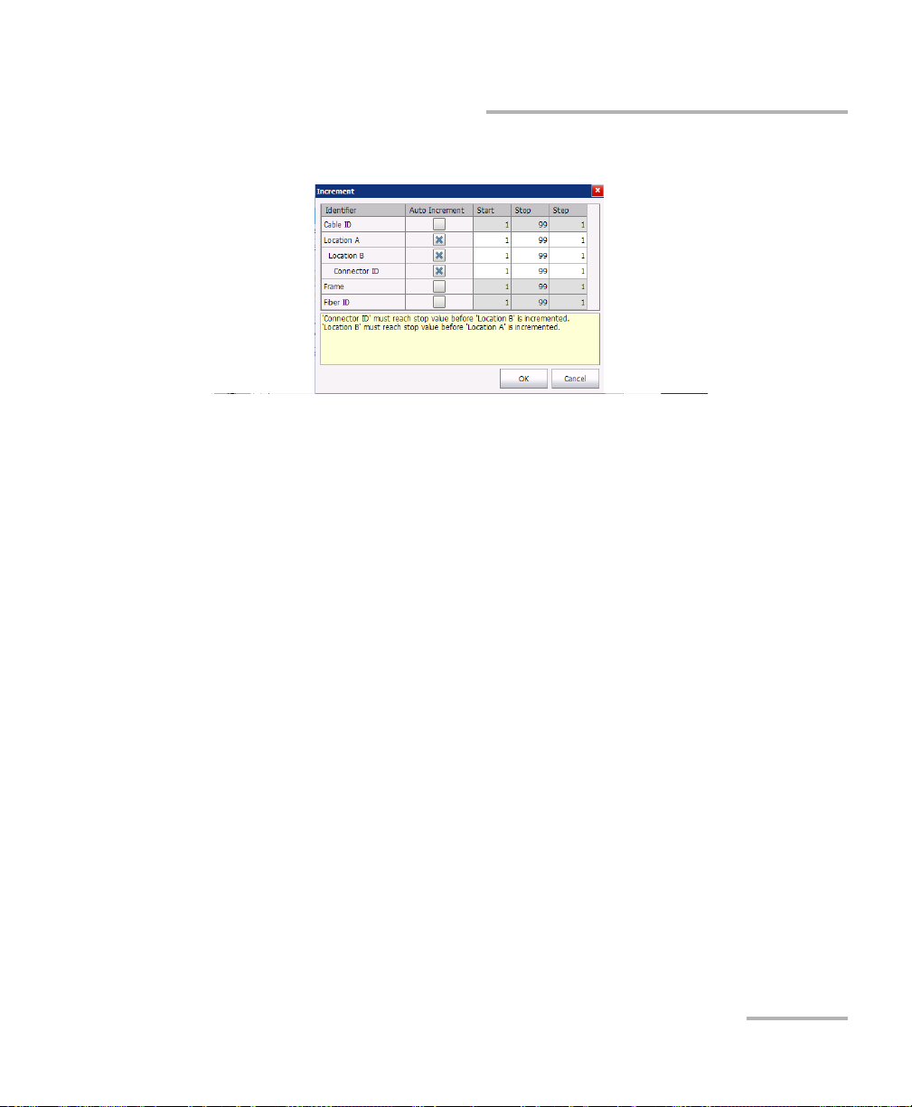
4. If you want to increment automatically the cable ID, the fiber ID, the
location (A and/or B), the Connector ID, or the Frame, proceed as
follows:
4a. Tap the Increment button.
4b. In the Increment window, select the Auto Increment check box
corresponding to the identifier you want to increment.
16 FIP-400B
Page 23
Setting up Your Fiber Inspection Probe and ConnectorMax2
Setting up Autonaming
4c. Enter the start, stop and increment values as desired.
Note: The identifiers are processed in order, from the one with the largest
indentation to the one with the smallest. For a given identifier, when the
increment value reaches the stop value, the incrementation automatically
switches to the next identifier. The order of the identifiers in the increment
window (and thereby the order of increment) follows the order of the
identification window.
Note: An identifier set to None will not appear in the increment window.
Note: To decrement values, the start number must be higher than the stop
number.
4d. Tap OK to return to the Identification window.
Fiber Inspection Probe 17
Page 24
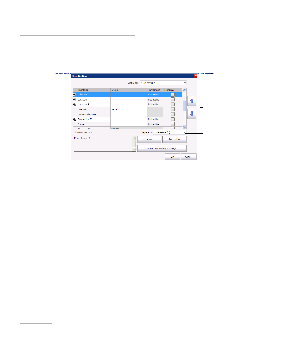
Setting up Your Fiber Inspection Probe and ConnectorMax2
Items that can be
included in the file
name
This preview is
updated
automatically as you
make your selections
To modify the order
of appearance of
the selected
identifiers in the
file name
To s e l e ct t h e
separator in the
automatic
numbering section
Setting up Autonaming
5. Select the desired identifiers to include in the file name. You can
change the order of appearance of the highlighted component with the
up and down arrow buttons.
6. Ta p OK to confirm your new settings and to return to the main window.
The new settings will apply the next time you perform a capture.
18 FIP-400B
Page 25
Setting up Your Fiber Inspection Probe and ConnectorMax2
Setting up Autonaming
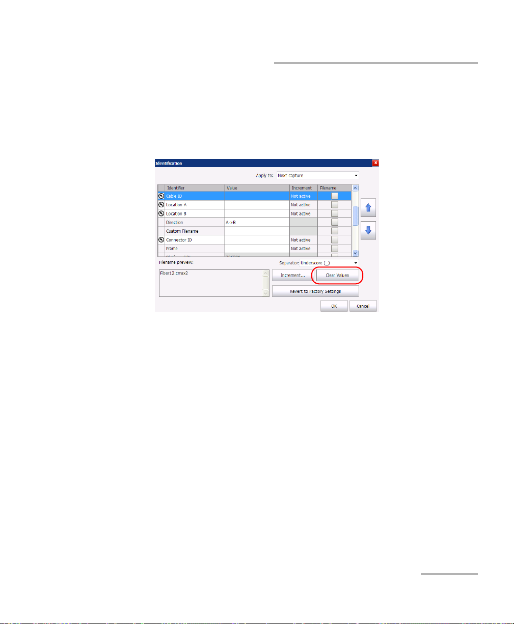
To clear the values:
1. From the Main Menu, tap Identification.
2. In the Apply to list, select Next capture.
3. Ta p the Clear Values button.
4. Ta p OK to return to the main window.
All values in the Value column are erased from the white boxes.
Fiber Inspection Probe 19
Page 26

Setting up Your Fiber Inspection Probe and ConnectorMax2
Managing and Selecting Test Configurations
Managing and Selecting Test Configurations
You can create and select specific test configurations according to the type
of fiber you are analyzing, the connector type or the type of anomaly you
are looking for.
Note: If you have the FIP-420B or FIP-430B probe, some test configurations as per
IEC 61300-3-35 and IPC 8497-1 standards, and other configurations with an
enlarged adhesive C zone are available by default.
Creating custom test configurations is done through duplicating an existing
configuration, and then modifying the desired criteria.
If you create configurations on one unit or computer, and want to transfer
them to another unit or computer, you can do so.
20 FIP-400B
Page 27
Setting up Your Fiber Inspection Probe and ConnectorMax2
Managing and Selecting Test Configurations
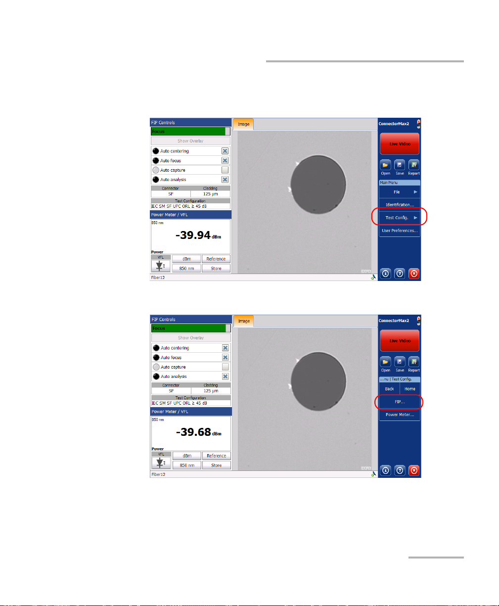
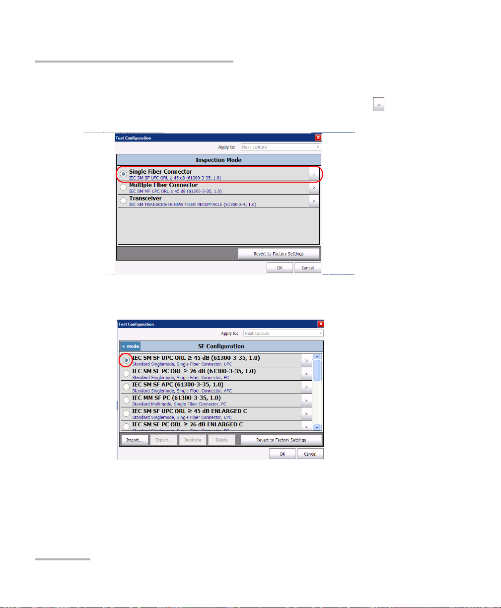
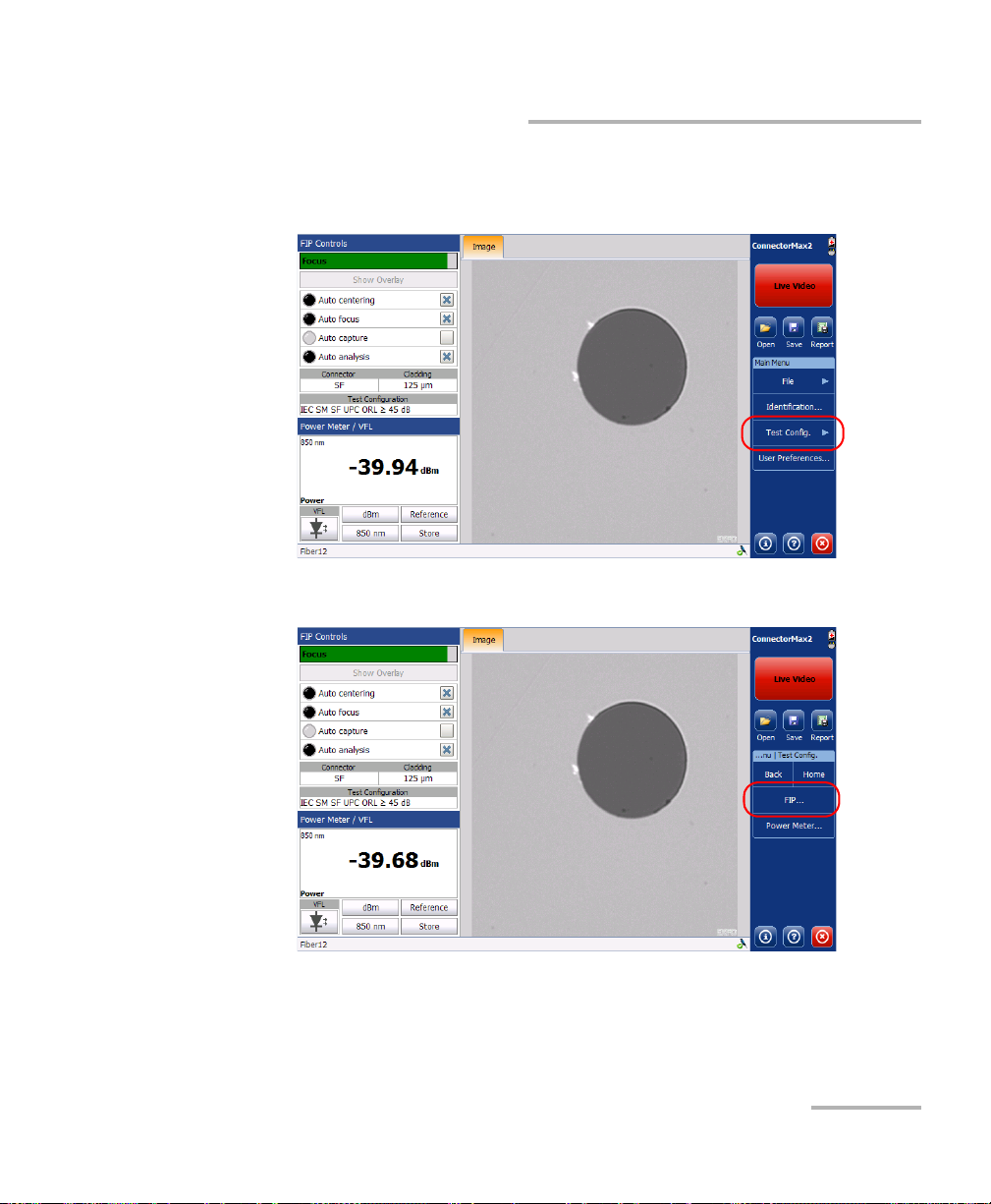
To select a test configuration:
1. From the Main Menu, select Te s t Con f ig.
2. Select FIP.
Fiber Inspection Probe 21
Page 28
Setting up Your Fiber Inspection Probe and ConnectorMax2
Managing and Selecting Test Configurations
3. If necessary, in the Apply to list, select Next capture.
4. Choose the type of connector you want to use and tap the button at
the end of the row.
5. In the list of available test configurations, select the configuration you
want to use and tap OK.
22 FIP-400B
Page 29
Setting up Your Fiber Inspection Probe and ConnectorMax2
Managing and Selecting Test Configurations
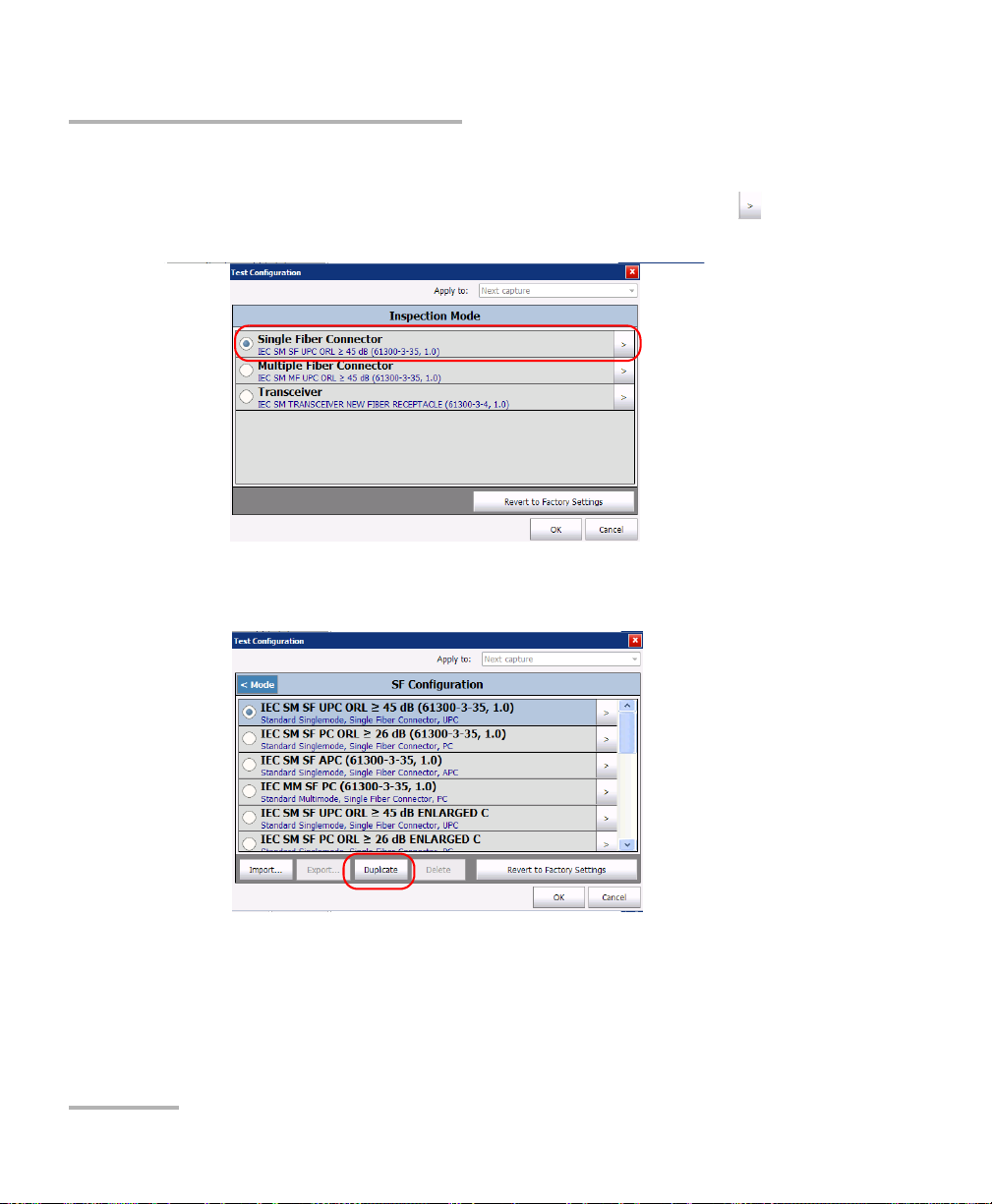
To create a test configuration:
1. From the Main Menu, select Te s t Con f ig.
2. Select FIP.
Fiber Inspection Probe 23
Page 30
Setting up Your Fiber Inspection Probe and ConnectorMax2
Managing and Selecting Test Configurations
3. If necessary, in the Apply to list, select Next capture.
4. Choose the type of connector you want to use and tap the button at
the end of the row.
5. Select the row corresponding to the configuration that is the closest to
the one you want to create, then tap Duplicate.
24 FIP-400B
Page 31

Setting up Your Fiber Inspection Probe and ConnectorMax2
Managing and Selecting Test Configurations
6. If you want to modify the general information, proceed as follows:
6a. In the Configuration Details window, tap the button at the
end of the Properties row.
6b. Modify the parameters as needed.
Configuration name: the application suggests a name for the
configuration. You can change it as needed (maximum 256
characters), but if you select a name that already exists, a suffix will
automatically be added so as not to overwrite files.
Connector type: Select which type of connector you are using for
your inspection.
Fiber type: Select whether you are inspecting singlemode or
multimode fibers.
Pol i shing typ e: Select the type of polishing for the fibers between
APC, PC or UPC.
Fiber Inspection Probe 25
Page 32

Setting up Your Fiber Inspection Probe and ConnectorMax2
Managing and Selecting Test Configurations
Analysis mode: Select the type of analysis between Outside plant
(selected by default) and Manufacturing. The manufacturing mode
is more sensitive for scratches and defects detection.
Cladding diameter: This value is set at 125 μm by default.
Zone diameters: You can change the zone dimension for single
fiber connectors and Transceiver fiber receptacles.
Note: Zone C (adhesive) cannot be removed and the superior diameter of zone D
cannot exceed 280 μm.
Note: When a multifiber connector is selected, zone D is not available.
Note: When you duplicate and edit a test configuration, you cannot change the
connector type field.
6c. Tap OK to confirm your choice and close the window.
OR
Use the Config. Details arrow to go back to the Configuration
Details window and configure other parameters.
26 FIP-400B
Page 33

Setting up Your Fiber Inspection Probe and ConnectorMax2
Managing and Selecting Test Configurations
7. If you want to modify the information about the inspection zones,
proceed as follows:
7a. Tap the button corresponding to the desired inspection zones.
7b. Modify the parameters as needed to indicate whether you want to
be notified of scratches, defects or both for each zone in the fiber,
then set thresholds for each item you select.
You can set up to 3 criteria per zone, and per anomaly type
(scratches or defects). The thresholds are divided into three
categories:
Any: this enables the next criterion, which requires a specific
value.
1 to 10: the next criterion is automatically filled out to show the
infinity symbol ( ) and 0 as a threshold.
0: the criterion definition is complete.
Fiber Inspection Probe 27
Page 34

Setting up Your Fiber Inspection Probe and ConnectorMax2
Managing and Selecting Test Configurations
7c. Tap OK to confirm your choice and close the window.
OR
Use the Config. Details arrow to go back to the Configuration
Details window and configure other parameters.
8. If necessary, use the Config. Details arrow to go back to the
Configuration Details window and tap OK to close the window.
OR
Use the FIP Config. arrow to go back to the FIP configuration list.
28 FIP-400B
Page 35

Setting up Your Fiber Inspection Probe and ConnectorMax2
Managing and Selecting Test Configurations
To edit a test configuration:
1. From the Main Menu, select Te s t Con f ig.
2. Select FIP.
Fiber Inspection Probe 29
Page 36

Setting up Your Fiber Inspection Probe and ConnectorMax2
Managing and Selecting Test Configurations
3. If necessary, in the Apply to list, select Next capture.
4. Choose the type of connector you want to use and tap the button at
the end of the row.
5. Select the configuration you want to edit and tap the button at the
end of the row.
Note: You cannot edit standard test configurations.
6. Change the criteria as required. For details, see the section on creating
a test configuration.
30 FIP-400B
Page 37

Setting up Your Fiber Inspection Probe and ConnectorMax2
Managing and Selecting Test Configurations
To delete a test configuration:
1. From the Main Menu, select Te s t Con f ig.
2. Select FIP.
Fiber Inspection Probe 31
Page 38

Setting up Your Fiber Inspection Probe and ConnectorMax2
Managing and Selecting Test Configurations
3. If necessary, in the Apply to list, select Next capture.
4. Choose the type of connector you want to use and tap the button at
the end of the row.
IMPORTANT
The application will not prompt you for confirmation before
deleting a configuration.
32 FIP-400B
Page 39

Setting up Your Fiber Inspection Probe and ConnectorMax2
Managing and Selecting Test Configurations
5. Select the row corresponding to the configuration you want to remove,
then tap Delete.
Note: You cannot delete standard test configurations.
Fiber Inspection Probe 33
Page 40

Setting up Your Fiber Inspection Probe and ConnectorMax2
Managing and Selecting Test Configurations
To import test configurations:
1. From the Main Menu, select Te s t Con f ig.
2. Select FIP.
34 FIP-400B
Page 41

Setting up Your Fiber Inspection Probe and ConnectorMax2
Managing and Selecting Test Configurations
3. Choose the type of connector you want to use and tap the button at
the end of the row.
4. From the FIP Configuration window, tap Import.
Fiber Inspection Probe 35
Page 42

Setting up Your Fiber Inspection Probe and ConnectorMax2
Managing and Selecting Test Configurations
5. From the Open dialog box, select the file you want to import.
6. Ta p OK to close the window.
36 FIP-400B
Page 43

Setting up Your Fiber Inspection Probe and ConnectorMax2
Managing and Selecting Test Configurations
To export test configurations:
1. From the Main Menu, select Te s t Con f ig.
2. Select FIP.
Fiber Inspection Probe 37
Page 44

Setting up Your Fiber Inspection Probe and ConnectorMax2
Managing and Selecting Test Configurations
3. Choose the type of connector you want to use and tap the button at
the end of the row.
4. From the FIP Configuration window, select the row corresponding to
the test configuration you want to export.
Note: You cannot export standard test configurations.
5. Ta p Export.
38 FIP-400B
Page 45

Setting up Your Fiber Inspection Probe and ConnectorMax2
Managing and Selecting Test Configurations
6. From the Save As dialog box, select the folder where you want to
export your file.
7. If desired, modify the file name.
8. Ta p OK to close the window.
Fiber Inspection Probe 39
Page 46

Setting up Your Fiber Inspection Probe and ConnectorMax2
Editing the Power Meter Test Configurations
Editing the Power Meter Test Configurations
You can activate and set pass/fail threshold parameters for your power
meter measurements. You can set thresholds for absolute power and
insertion loss. You can set different pass/fail thresholds for each available
test wavelength, or apply the same thresholds to all wavelengths. Values
that are greater than the predefined thresholds are displayed in white on a
red background. Values that are pass are displayed in green.
To edit the power meter test configurations:
1. From the Main Menu, select Te s t Con f ig.
40 FIP-400B
Page 47

Setting up Your Fiber Inspection Probe and ConnectorMax2
Editing the Power Meter Test Configurations
2. Select Power Meter.
3. In the Apply to list, select Next capture.
4. Select the desired wavelength.
5. Set the pass/fail thresholds for the selected wavelength.
Note: You can apply the settings to all wavelengths.
Fiber Inspection Probe 41
Page 48

Setting up Your Fiber Inspection Probe and ConnectorMax2
Reverting to Factory Settings
6. Choose the absolute power units.
7. If you want to see the pass/fail status, check the Apply thresholds
(Pass/Fail status) option.
Reverting to Factory Settings
At any time in the application, you can revert to factory settings in your
menus. However, the Restore to Factory Settings button is valid only for
the window or tab where you use it.
42 FIP-400B
Page 49

Setting up Your Fiber Inspection Probe and ConnectorMax2
Changing Fiber Information of Existing Captures
Changing Fiber Information of Existing
Captures
It is possible to modify the information for an existing capture. This
information is provided by the automatic file naming. The procedure is
almost the same as the one for autonaming but the changes apply to the
current capture only.
To change fiber information:
1. From the Main Menu, tap Identification.
2. From the Apply to list, ensure that Current capture is selected.
3. Set the parameters as needed. For more information, see Setting up
Autonaming on page 12.
Fiber Inspection Probe 43
Page 50

Page 51

4 Inspecting Fiber Ends
Viewing the fiber inspection is done using ConnectorMax2. You can start
the application before or after connecting the probe, and the view
on-screen will be automatically updated.
WARNING
Never look directly into a live fiber. It could cause serious eye
damage. Always use your FIP-400B Fiber Inspection Probe.
Inspecting Fiber Ends (Single Fiber and Transceiver - Fiber Receptacles)
When you connect the FIP-400B Fiber Inspection Probe to your unit, you
can view and inspect fiber ends right away. This direct viewing mode is
known as the Live mode.
Since the available controls depend on the probe that is connected, if you
disconnect the probe, the application will show an empty window. The
controls become available again as soon as you reconnect the probe (no
need to restart the application).
Note: When the internal temperature of the FIP-430B is too low, the probe
performs a warm-up that can take up to a minute.
You can also capture images of your inspections to include in reports, or
save them for future analyses. This is known as the Capture mode.
A digital watermark is added to the images generated by the application.
This also applies to ConnectorMax1 files converted to the ConnectorMax2
format.
Fiber Inspection Probe 45
Page 52

Inspecting Fiber Ends
Inspecting Fiber Ends (Single Fiber and Transceiver - Fiber Receptacles)
The focus indicator, which is displayed in the upper left part of the main
window, indicates whether the current view is optimized for a capture. A
green indicator shows a picture that can be captured and analyzed.
Analysis will be more difficult with a yellow indicator, and impossible with
a red indicator. A vertical black bar displays the peak focus level.
Note: The peak focus level is shown only when the auto focus sequence is
complete.
For more information on analysis, see Analyzing Captures on page 64.
To inspect fiber ends (single fiber) in Live mode:
1. Install a probe tip (see Changing the Fiber Inspection Probe Tip on
page 9).
2. Insert the fiber into the probe tip.
3. Connect your Fiber Inspection Probe to your unit. On an FTB-500,
connect the probe to the lower USB port located on the front of the
unit.
46 FIP-400B
Page 53

Inspecting Fiber Ends
Inspecting Fiber Ends (Single Fiber and Transceiver - Fiber Receptacles)
4. Start ConnectorMax2 if it is not already started.
5. Ensure to configure the automatic file naming (see Setting up
Autonaming on page 12).
6. Choose the type of connector you want to use (SF or Transceiver).
Fiber Inspection Probe 47
Page 54

Inspecting Fiber Ends
Inspecting Fiber Ends (Single Fiber and Transceiver - Fiber Receptacles)
7. Depending on the probe you are using, proceed as follows:
If you have an FIP-420B, activate the auto centering, then adjust the
magnification level and the image focus to have the best view of
the fiber end.
If you have an FIP-430B, activate the auto centering and the auto
focus.
For more information, see Analyzing Captures on page 64.
8. If the fiber end is dirty, remove it from the probe, clean it and
reinspect it.
9. Once you are satisfied with the inspection, when in high magnification
level, press Capture.
OR
Press the Fiber Inspection Probe handset button.
10. Go to the next connector or close the application.
48 FIP-400B
Page 55

Inspecting Fiber Ends
Setting Up Multifiber Inspection
Setting Up Multifiber Inspection
Inspecting and analyzing multifiber connectors can be done separately for
each fiber, or as a batch.
When the inspection and the analysis are done separately, there is a
transition between the Live Video mode and the Capture mode after an
image is captured.
To speed up the process of inspecting and analyzing connectors and fibers,
you can use the batch inspection feature. With this feature, all fibers are
captured and previewed one after the other for a configured period of
time. Then the analysis is launched when all fibers are inspected.
To use the batch inspection and analysis process:
1. From the main window, select User Preferences.
2. Select the MF Connector tab.
3. Choose Use batch inspection or analysis process (applies to the
next capture).
This enables the preview duration time box.
4. Enter the time you want the preview to last.
5. Ta p OK to confirm your choice and close the window.
Fiber Inspection Probe 49
Page 56

Inspecting Fiber Ends
Displaying Multifiber Connector Overlay
Displaying Multifiber Connector Overlay
By default, ConnectorMax2 displays the multifiber overlay only in high
magnification. The overlay is used to see which of the connectors in a
multifiber connector is being inspected. It is possible to see four fibers at a
time when the overlay is displayed.
Note: The FIP-410B probe does not display the overlay in multifiber.
To display the multifiber connector overlay:
1. From the main window, select User Preferences.
2. Select the MF Connector tab.
3. Choose Include multifiber connector overlay.
4. Ta p OK to confirm your choice and close the window.
50 FIP-400B
Page 57

Inspecting Fiber Ends
Inspecting Fiber Ends (Multifiber)
In the main window, a blue arrow now indicates the fiber under test.
Inspecting Fiber Ends (Multifiber)
The multifiber inspection with a FIP-430B probe allows you to see multiple
fibers at a time.
You can capture images of your inspections to include in reports, or save
them for future analyses. This is known as the Capture mode.
A digital watermark is added to the images generated by the application.
This also applies to ConnectorMax1 files converted to the ConnectorMax2
format.
Fiber Inspection Probe 51
Page 58

Inspecting Fiber Ends
Inspecting Fiber Ends (Multifiber)
The focus indicator, which is displayed in the upper left part of the main
window, indicates whether the current view is optimized for a capture. A
green indicator shows a picture that can be captured and analyzed.
Analysis will be more difficult with a yellow indicator, and impossible with
a red indicator. A vertical black bar displays the peak focus level.
Note: The peak focus level is shown only when the auto focus sequence is
complete.
To speed up the process of inspecting and analyzing connectors and fibers,
you can use the batch inspection feature. With this feature, all fibers are
captured and previewed one after another for a configured period of time.
Then the analysis is launched when all fibers are inspected.
For more information on analysis, see Analyzing Captures on page 64.
52 FIP-400B
Page 59

Inspecting Fiber Ends
Inspecting Fiber Ends (Multifiber)
To inspect fiber ends (multifiber) in Live mode:
1. Install a probe tip (see Changing the Fiber Inspection Probe Tip on
page 9).
2. Insert the fiber into the probe tip.
3. Insert replaceable APC or UPC nozzle in and tighten it (turn
clockwise).
4. For patchcord inspection, insert a mating tip.
5. Connect your Fiber Inspection Probe to your unit. On an FTB-500,
connect the probe to the lower USB port located on the front of the
unit.
Fiber Inspection Probe 53
Page 60

Inspecting Fiber Ends
Inspecting Fiber Ends (Multifiber)
6. Start ConnectorMax2 if it is not already started.
7. Ensure to configure the automatic file naming (see Setting up
Autonaming on page 12).
8. Choose the type of connector you want to use (MF).
OR
Tap File, then New.
54 FIP-400B
Page 61

Inspecting Fiber Ends
Inspecting Fiber Ends (Multifiber)
9. Choose the type of connector you want to use between MTP/MPO
(selected by default) or Optitap.
10. Depending on the probe you are using, proceed as follows:
If you have an FIP-420B, activate the auto centering.
If you have an FIP-430B, activate the auto centering and the auto
focus.
For more information, see Analyzing Captures on page 64.
11. Set the probe to Low Magnification and locate the first fiber.
Fiber Inspection Probe 55
Page 62

Inspecting Fiber Ends
Y wheel
X wheel
Inspecting Fiber Ends (Multifiber)
12. Set the probe to High Magnification.
Note: The FIP-420B and FIP-430B probes show a low magnification connector
image in the overlay.
13. Center the appropriate connector in the array:
For multi-row tips, use the Y wheel to select the required fiber row.
For multi-row and single-row tips, use the X wheel to select the
required fiber.
56 FIP-400B
Page 63

Inspecting Fiber Ends
Inspecting Fiber Ends (Multifiber)
14. View results on screen.
Note: The auto-focus starts automatically only for the first fiber (FIP-430B only).
Hold the magnification control button located on the probe for
one second to reactivate the auto-focus process (FIP-430B only).
OR
Adjust focus manually.
15. If the fiber end is dirty, remove it from the probe, clean it and
reinspect it.
16. When in high magnification level, press Capture.
OR
Press the Fiber Inspection Probe handset button.
17. If you are not using the batch inspection feature, return to Live Video
mode. Repeat steps 13 to 17 until you reach the end of the connector.
18. If you are using the batch inspection feature, press Process.
OR
To continue the current connector inspection, return to Live Video
mode.
19. To inspect a new connector, tap File, then New.
Fiber Inspection Probe 57
Page 64

Inspecting Fiber Ends
Retesting a Fiber (Multifiber)
Retesting a Fiber (Multifiber)
Sometimes, a capture will show a fail status, but it could only be because
the fiber is dirty and you want to clean it and test it again. However, if you
have saved the file, the next capture you take will be incremented instead
of replacing the current file.
In order to avoid this incrementation and end up with unwanted files, you
can test a fiber again.
To retest a fiber in Live Video mode:
1. Use the list to navigate between the captured fibers.
2. Ta p Capture.
58 FIP-400B
Page 65

Inspecting Fiber Ends
To v i e w n e x t fi b e r
To view previous fiber
To r e t es t a f i b er
To minimize or maximize
the navigation toolbar
Pass/Fail status for current SF
Retesting a Fiber (Multifiber)
To retest a fiber in Capture mode:
1. Use the list to navigate between the captured fibers.
2. Ta p Reset.
Fiber Inspection Probe 59
Page 66

Inspecting Fiber Ends
Saving Files
Saving Files
In Capture mode, you can save the acquisition files manually for future
reference.
You can also set ConnectorMax2 so that it saves the capture automatically
regardless of the result, or automatically when the result is Pass only.
Note: Saving a file automatically after a capture is not possible in multifiber
mode.
Note: When you return to the Live mode, your file name structure will be
automatically incremented or decremented so that you do not overwrite
your work.
To save files automatically, or automatically only when the status
is set to Pass:
1. From the main window, select User Preferences.
60 FIP-400B
Page 67

Inspecting Fiber Ends
Saving Files
2. Select the General tab.
3. Select whether you want the capture to be automatically saved
regardless of the result (all models), saved if the result of the analysis is
pass (only available with the FIP-420B and FIP-430B models), or select
the manual save option if you only want to save specific files.
4. If you want to change the default location where the files will be saved,
you can do so by using the button.
5. Ta p OK to confirm your choice.
Fiber Inspection Probe 61
Page 68

Inspecting Fiber Ends
Saving Files
To s av e a f il e:
From the main window, tap the button.
OR
Select the File menu, then Save to overwrite an existing file.
OR
Select the File menu, then Save As to change the file name or location.
Note: If you change the location for saving the files, this location will remain as
the default location for the remainder of the work session, or until you
change the location again.
IMPORTANT
If you have enabled the Generate report on save option, the new
report file will automatically overwrite the old one without
notifying you.
62 FIP-400B
Page 69

Inspecting Fiber Ends
Opening and Closing Files
Opening and Closing Files
You can open captured files directly from the application to view them.
You can either open current .cmax2 files, .cmax files (not supported by
MAX-700B and MAX-FIP), or a legacy image file taken from a previous fiber
inspection.
The .cmax files, when saved with the ConnectorMax 2 application, are
compatible with ConnectorMax2 files. However, the .cmax2 files can be
opened with the ConnectorMax 2 application only.
Note: The accepted image formats for legacy files are .bmp, .jpg and .gif.
Note: Sample files are available on the platform.
To o pe n a f il e:
1. From the main window, select File, and then Open.
2. Select the desired file, and then tap OK.
Fiber Inspection Probe 63
Page 70

Inspecting Fiber Ends
Analyzing Captures
Analyzing Captures
With the capture analysis option (FIP-420B and FIP-430B), you can perform
automated pass/fail analyses according to the criteria you have set.
Note: Analysis is not available for the FIP-410B.
Depending on the fiber probe that you have, you may have access to the
following features:
auto centering: The auto centering displays the fiber in the middle of
the image. It is compatible with all connector types and fiber with a
cladding of 125 μm. The auto centering is enabled only in high
magnification. Working with the auto centering feature can be useful
with standard connectors. When inspecting special connectors, it is
also possible to uncheck the auto centering check box.
auto focus: The auto focus focuses on the connector image. It is
enabled if the auto centering is activated and only in high
magnification. The auto focus is only possible in Live video mode and if
the focus is not done manually. It starts automatically when you insert
an optical fiber connector. For more information, see Fiber Inspection
Probe Tip Compatibility Chart on page 95.
auto capture: The auto capture is possible with an acceptable focus
level. It is enabled if the auto centering and auto focus are activated.
The auto capture is possible only in high magnification. For the
FIP-430B probe, the auto capture is not displayed when a multifiber
connector is selected.
auto analysis: The auto analysis displays 4 inspection zones: core,
cladding, adhesive, and contact. It is enabled only in high
magnification. When a multifiber connector is selected, the auto
analysis is available for zone A and B only.
64 FIP-400B
Page 71

Inspecting Fiber Ends
Analyzing Captures
An indicator is located at the left of the available features. The color of this
indicator shows the status of the feature:
Color Meaning
Grey The item is not selected
Green The item is selected and the
conditions allow the analysis.
Black
The item is selected but the
conditions do not allow the
analysis.
The auto focus process was
aborted by the user.
Red The application is in timeout state
because it is unable to complete the
auto focus process. There are three
ways to reapply the auto focus:
Clear the auto focus check box
and select it again
Press the FIP-400B magnification
button for 1 second
From Capture mode, return to
Live video mode
Fiber Inspection Probe 65
Page 72

Inspecting Fiber Ends
Analyzing Captures
To select the analysis features:
Select the features you need for the capture.
The analysis results are available as soon as you tap Process. Fibers are
analyzed sequentially. The process time depends on the number of fibers
to be analyzed.
The global status is displayed in the upper right part of the window after an
analysis. The Image and Results tabs are displayed when a capture is
made (using the button from the button bar or on the probe). When you
are ready to inspect another fiber, you have to return to the Live video
mode first.
To disable the analysis features:
Clear the check box next to the corresponding features.
66 FIP-400B
Page 73

Inspecting Fiber Ends
Analyzing Captures
The Image tab shows the snapshot of the fiber when you captured it.
You can see all the anomalies that have been detected.
The overlay shows the status of the analysis, the status per zone, the
analysis zones, any anomaly (defects, scratches) found on the fiber
endface, and the global status in the upper right part of the main
window. The color of the circles shows the status of the analysis zone:
Green: pass
Blue: no analysis was performed or the function is disabled
Red: fail
Note: You can change the diameter of the analysis zones. For more information,
see Managing and Selecting Test Configurations on page 20.
Fiber Inspection Probe 67
Page 74

Inspecting Fiber Ends
Analyzing Captures
By default, the overlay is shown after an analysis, but you can hide it
using the Hide Overlay button.
The Results tab shows detailed information for scratches and defects
detected in each test zone and the corresponding test status.
Note: When there is no analysis, the Results tab does not appear.
68 FIP-400B
Page 75

Inspecting Fiber Ends
Displaying or Hiding the Power Meter and VFL Controls
Displaying or Hiding the Power Meter and VFL
Controls
By default, the power meter and VFL controls are displayed in the left side
bar of the main window. However, you can hide them. This option is
present on all platforms even if no power meter or VFL is available, except
on computers.
To display or hide the power meter and VFL controls:
1. From the main window, select User Preferences.
2. Select the General tab.
3. Under Display, select Display power meter/VFL controls.
4. Ta p OK to confirm your choice and close the window.
Fiber Inspection Probe 69
Page 76

Inspecting Fiber Ends
Clearing Power Meter Measurements Automatically
Clearing Power Meter Measurements
Automatically
Measurements can be automatically erased from memory upon returning
to the Live video mode. This option is present on all platforms even if no
power meter is available, except on computers.
To clear power meter measurements automatically:
1. From the main window, select User Preferences.
2. Select the General tab.
3. Under Stored Measurements, select Clear power meter
measurements upon switching to live video.
4. Ta p OK to confirm your choice and close the window.
70 FIP-400B
Page 77
Inspecting Fiber Ends
Measuring Power or Insertion Loss
Measuring Power or Insertion Loss
If your unit is equipped with a power meter, ConnectorMax2 provides
power meter measurements. The power meter view displays current
power and loss measurements. This view is available either in Live mode
or Capture mode.
For the MAX-700B platform, you can either perform measurements
manually and select each wavelength yourself, or you can use the
auto-wavelength and auto-switching modes of your source.
Note: When there is a selected wavelength and the source is in Auto mode, the
power meter switches automatically to Auto mode.
The correction factors and the offset nulling are not supported by
ConnectorMax2. For more information on your power meter, refer to the
corresponding user guide.
Fiber Inspection Probe 71
Page 78

Inspecting Fiber Ends
Switches
between
current
measurement
and stored
measurement
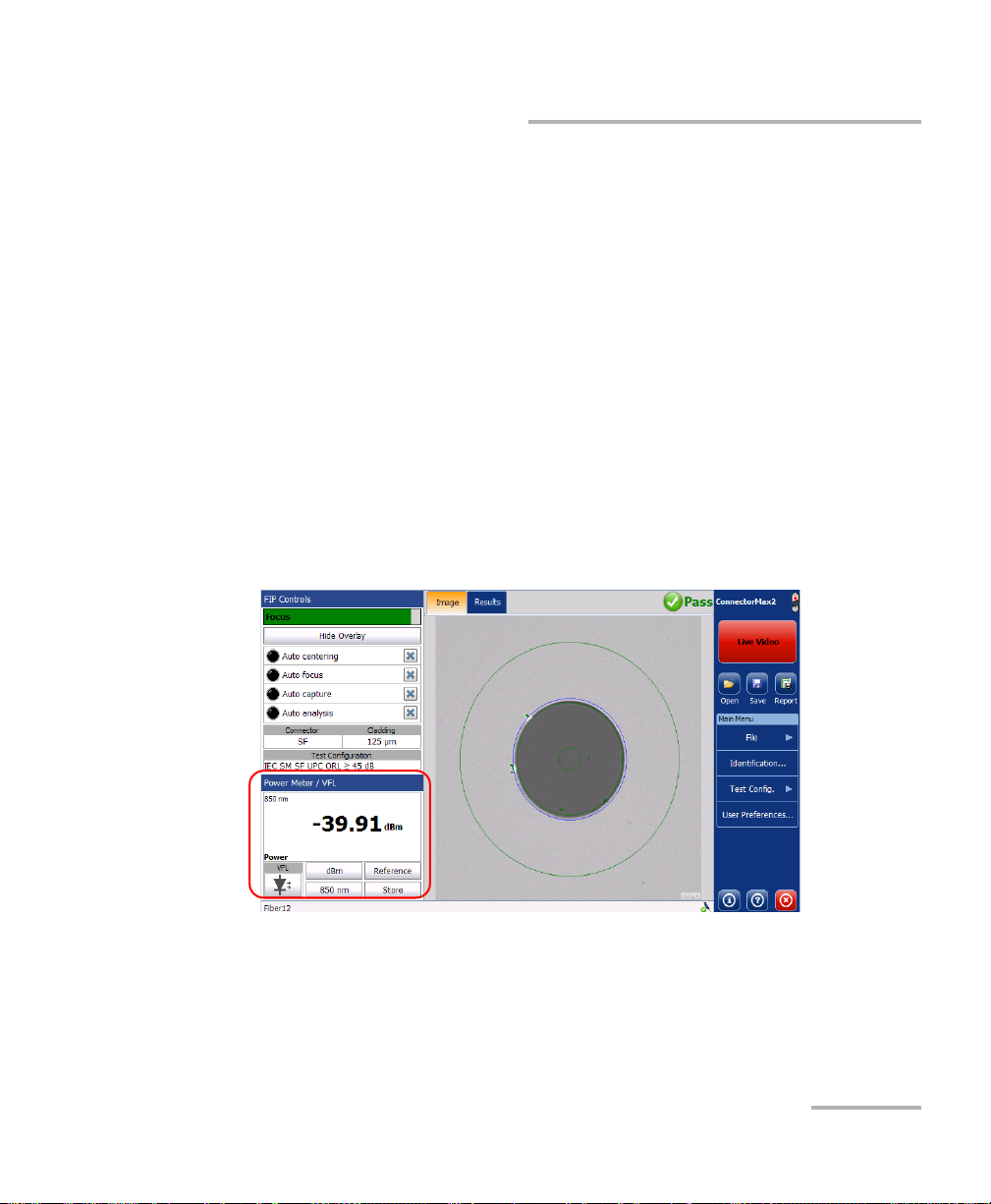
Viewing Power Meter Results
Viewing Power Meter Results
You can view the power meter results stored in memory in a separate tab
(see Measuring Power or Insertion Loss on page 71). The global pass/fail
status also takes the power meter measurements into account.
To view power or insertion loss measurements:
Select the Power Meter tab. All your measurements are displayed in the
order they were performed.
72 FIP-400B
Page 79

Inspecting Fiber Ends
Identifying Fiber Faults Visually with the VFL
Identifying Fiber Faults Visually with the VFL
Your unit can be equipped with an optional visual fault locator (VFL) to
help you identify bends, faulty connectors, splices and other causes of
signal loss. It can also help the person at the other end of the link to identify
the fiber under test, which could be particularly useful when working with
cables containing many fibers.
From its dedicated port, the VFL emits a red signal which becomes visible
at the location of a fault on the fiber. This signal can be continuous (CW) or
blinking (1 Hz).
The VFL is available either in Live mode or Capture mode. It can be
switched from one state to another (on, off or blink).
WARNING
When the VFL is active, the VFL port emits visible laser radiation.
Avoid exposure and do not stare directly into the beam. Protect any
unused port with a cap.
Fiber Inspection Probe 73
Page 80

Inspecting Fiber Ends
Creating Reports
Creating Reports
You can create a report based on the current inspection and analysis
results. This report can be saved in the following formats: PDF, HTML and
MHTML.
However, HTML and MHTML reports are not supported on the MAX-700B
and MAX-FIP platforms.
Note: The report creation is available only in Capture mode.
Note: The report may include the OPM results or not. Even if there are no OPM
results, the report title still mentions OPM results and the global pass/fail
includes both FIP and OPM results.
If you have selected the Generate report on save option, a report is
automatically created when you save your capture.
IMPORTANT
Your application has been designed for optimal viewing of the fonts
shown in reports in all supported languages. Ensure the language
settings for Non-Unicode applications remains to English (United
States).
74 FIP-400B
Page 81

Inspecting Fiber Ends
Creating Reports
To activate automated report creation:
1. From the main window, select User Preferences.
2. Select the General tab.
3. Under File Functionalities, select Generate report on save.
4. Ta p OK to confirm your choice and close the window.
Fiber Inspection Probe 75
Page 82

Inspecting Fiber Ends
Creating Reports
To create a report manually:
1. From the main window, tap .
OR
Select the File menu, then Report.
2. From the Save As dialog box, select a folder or create one to save your
file.
76 FIP-400B
Page 83

Inspecting Fiber Ends
Updating the Firmware and Software
3. If desired, modify the file name.
4. Ta p OK to close the window.
You can now open the report with PDF reader from the location where the
file was saved. The HTML and MHTML reports are compatible with Internet
Explorer (IE 7 and latest), and the latest software release of FireFox and
Google Chrome.
Updating the Firmware and Software
The FIP-400B is designed to provide automatic software update
notifications and firmware updates whenever necessary. This allows you to
benefit from the updates of your unit each time you use it. The firmware
and software updates can be recommended or required.
To notify you, a message box appears each time a firmware or software
update is recommended.
When a firmware update is required, the application shows an error if you
choose not to update the FIP-400B. If a firmware update fails,
ConnectorMax2 performs a fault recovery procedure the next time the
FIP-400B is connected.
The FIP-400B becomes unavailable if a software update is required or
when a firmware update is in progress. The Live video button becomes
disabled in capture view and in video view, the capture button becomes
disabled as well.
CAUTION
Do not disconnect the probe or turn off the unit when an update is
in progress.
Fiber Inspection Probe 77
Page 84

Inspecting Fiber Ends
Updating the Firmware and Software
Once an update is started, follow the indications to complete the process.
During the automatic upgrade of the firmware of your FIP-400B
probe, you may be prompted to install USB drivers for your
instrument. In that case, you need to map your fiber inspection
probe with the necessary driver.
To be notified of the firmware or software updates
automatically:
1. From the main window, select User Preferences.
2. Select the General tab.
3. Under Display, choose the appropriate option.
IMPORTANT
4. Ta p OK to confirm your choice and close the window.
Note: By default, both check boxes are selected.
78 FIP-400B
Page 85

Inspecting Fiber Ends
Updating the Firmware and Software
To configure the USB driver for your fiber inspection probe:
1. Confirm the firmware upgrade when ConnectorMax2 prompts you.
2. During the upgrade process, the Found New Hardware wizard can be
displayed. In this case, if the application prompts you to connect to
Windows Update to search for software, select No, not this time, and
then click Next.
3. Make sure that the Install the software automatically
(Recommended) option is selected, and click Next.
Fiber Inspection Probe 79
Page 86

Inspecting Fiber Ends
Updating the Firmware and Software
4. The wizard may display a warning message indicating that the
hardware has not passed Windows Logo testing. In this case, since it
has been verified that the drivers work with Windows, click Continue
Anyway.
5. Follow the on-screen instructions, and then click Finish when the
installation is complete.
6. When the application displays an error message indicating that the FIP
firmware update has failed, click OK to close the message.
The automatic upgrade process will continue normally since the driver
has been associated with your fiber inspection probe already.
Note: If the application continues to display the firmware update error message
even after the driver has been associated correctly with your fiber
inspection probe, contact technical support.
80 FIP-400B
Page 87

5 Maintenance
General Maintenance
To help ensure long, trouble-free operation:
Keep the unit free of dust.
Clean the unit casing and front panel with a cloth slightly dampened
with water.
Store unit at room temperature in a clean and dry area. Keep the unit
out of direct sunlight.
Avoid high humidity or significant temperature fluctuations.
Avoid unnecessary shocks and vibrations.
If any liquids are spilled on or into the unit, turn off the power
immediately and let the unit dry completely.
The use of controls, adjustments and procedures other than those
specified herein may result in exposure to hazardous situations or
impair the protection provided by this unit.
WARNING
Recycling and Disposal (Applies to European Union Only)
For complete recycling/disposal information as per European Directive
WEEE 2012/19/UE, visit the EXFO Web site at www.exfo.com/recycle.
Fiber Inspection Probe 81
Page 88

Page 89

6 Troubleshooting
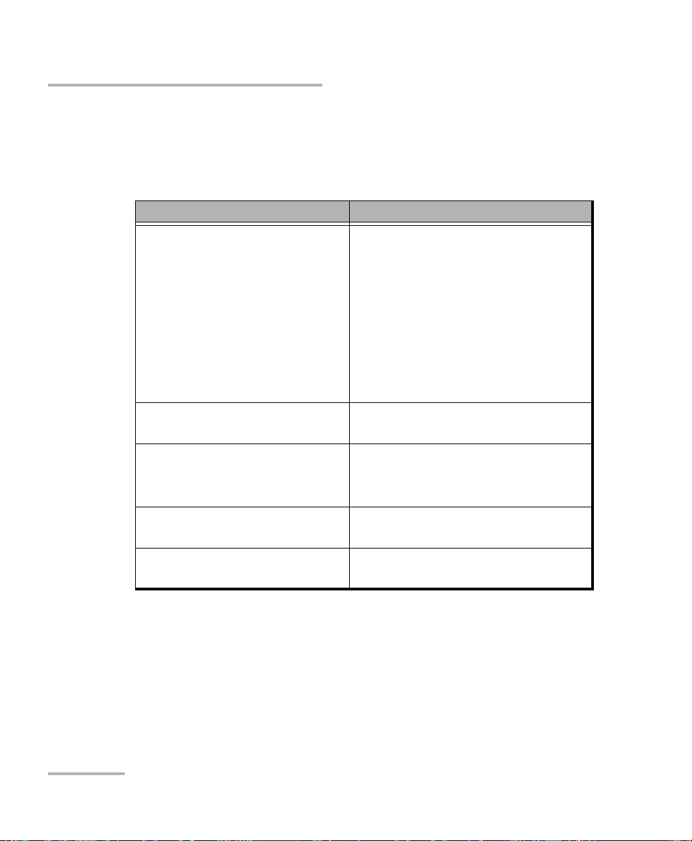
Solving Common Problems
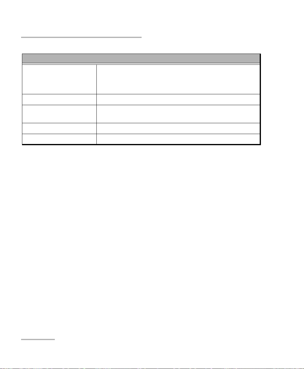
The table below presents common problems and their solutions.
Problem Solution
I cannot analyze an
image
I cannot see the fiber
on-screen
The FIP internal
temperature is too high
The FIP has encountered
a critical internal error
The image is not focused properly; use the focus knob on
the probe until the focus indicator displays the best value
available. Yellow indicates an acceptable range, and
green shows the preferred range.
Ensure that the probe is connected properly.
Ensure that the connector is aligned properly.
Ensure that the focus value is sufficient to perform the
analysis.
Ensure that you are using a high magnitude level.
Connect the probe to the USB port of the unit.
Verify the probe connection status to see if
ConnectorMax2 is detecting the probe properly. If the
probe is connected properly, close ConnectorMax2 and
open it again.
If you are working with a FTB-500, ensure that the probe
is connected to the lower USB port located in front of the
unit.
Let the FIP cool down.
Contact EXFO for technical support.
Violation of EXFO
embedded software
copyright
The auto centering does
not function properly
Fiber Inspection Probe 83
Contact EXFO for technical support.
Clean the connector.
Adjust the image focus.
Page 90

Troubleshooting
Solving Common Problems
Problem Solution
The analysis was
interrupted before it was
complete
FIP_ERROR_CODE_101
A connection error
occurred
An APC fiber is
connected to an
FIP-430B probe, the blue
LED is blinking and the
motor is not running
Refresh rate is very low
On a computer, in Live
video mode, the probe
no longer works when it
loses its focus
Ensure that the Live video mode is selected.
Adjust the image settings.
Ensure that the probe is not currently in use by another
application.
Try to connect the probe again.
When the fiber connector is detected, this will then initiate
the auto-focus sequence.
Ensure that the CPU throttling is not in degrade mode.
Choose another power scheme which is not Max Battery.
For more information about power scheme, refer to the
power management options section in your platform user
guide.
Tap anywhere in the application window to bring it back to
the front.
The firmware update
Disconnect the probe and try to connect it again.
fails when the driver
installation process is too
long.
84 FIP-400B
Page 91

Problem Solution
Troubleshooting
Solving Common Problems
On a Dell computer, the
same image is displayed
twice, one on top of the
other, when the Dell
Webcam Central
software is installed and
the Show Original Video
option is enabled.
An error message
regarding the
initialization of the
application may appear
when starting the
ConnectorMax2
application.
Ensure to disable the Show Original Video option.
You must install .NET Framework 3.5 SP1 or higher on your
unit.
Fiber Inspection Probe 85
Page 92

Troubleshooting
Contacting the Technical Support Group
Contacting the Technical Support Group
To obtain after-sales service or technical support for this product, contact
EXFO at one of the following numbers. The Technical Support Group is
available to take your calls from Monday to Friday, 8:00 a.m. to 7:00 p.m.
(Eastern Time in North America).
Technical Support Group
400 Godin Avenue
Quebec (Quebec) G1M 2K2
CANADA
For detailed information about technical support, and for a list of other
worldwide locations, visit the EXFO Web site at www.exfo.com.
If you have comments or suggestions about this user documentation, you
can send them to customer.feedback.manual@exfo.com.
To accelerate the process, please have information such as the name and
the serial number (see the product identification label), as well as a
description of your problem, close at hand.
1 866 683-0155 (USA and Canada)
Tel.: 1 418 683-5498
Fax: 1 418 683-9224
support@exfo.com
86 FIP-400B
Page 93

Troubleshooting
Viewing Information about ConnectorMax2
Viewing Information about ConnectorMax2
You can view information about ConnectorMax2 such as the version
number and contact information for technical support in the About
window.
To view ConnectorMax2 information:
From the main window, tap .
Viewing Online Help
You can view the online help for ConnectorMax2 at any time.
To view the online help:
From the main window, tap .
Transportation
Maintain a temperature range within specifications when transporting the
unit. Transportation damage can occur from improper handling. The
following steps are recommended to minimize the possibility of damage:
Pack the unit in its original packing material when shipping.
Avoid high humidity or large temperature fluctuations.
Keep the unit out of direct sunlight.
Avoid unnecessary shocks and vibrations.
Fiber Inspection Probe 87
Page 94

Page 95

7 Warranty
General Information
EXFO Inc. (EXFO) warrants this equipment against defects in material and
workmanship for a period of one year from the date of original shipment.
EXFO also warrants that this equipment will meet applicable specifications
under normal use.
During the warranty period, EXFO will, at its discretion, repair, replace,
or issue credit for any defective product, as well as verify and adjust the
product free of charge should the equipment need to be repaired or if the
original calibration is erroneous. If the equipment is sent back for
verification of calibration during the warranty period and found to meet all
published specifications, EXFO will charge standard calibration fees.
The warranty can become null and void if:
unit has been tampered with, repaired, or worked upon by
unauthorized individuals or non-EXFO personnel.
warranty sticker has been removed.
IMPORTANT
case screws, other than those specified in this guide, have been
removed.
case has been opened, other than as explained in this guide.
unit serial number has been altered, erased, or removed.
unit has been misused, neglected, or damaged by accident.
THIS WARRANTY IS IN LIEU OF ALL OTHER WARRANTIES EXPRESSED,
IMPLIED, OR STATUTORY, INCLUDING, BUT NOT LIMITED TO, THE
IMPLIED WARRANTIES OF MERCHANTABILITY AND FITNESS FOR A
PARTICULAR PURPOSE. IN NO EVENT SHALL EXFO BE LIABLE FOR
SPECIAL, INCIDENTAL, OR CONSEQUENTIAL DAMAGES.
Fiber Inspection Probe 89
Page 96

Warranty
Liability
Liability
EXFO shall not be liable for damages resulting from the use of the product,
nor shall be responsible for any failure in the performance of other items to
which the product is connected or the operation of any system of which
the product may be a part.
EXFO shall not be liable for damages resulting from improper usage or
unauthorized modification of the product, its accompanying accessories
and software.
Exclusions
EXFO reserves the right to make changes in the design or construction of
any of its products at any time without incurring obligation to make any
changes whatsoever on units purchased. Accessories, including but not
limited to fuses, pilot lamps, batteries and universal interfaces (EUI) used
with EXFO products are not covered by this warranty.
This warranty excludes failure resulting from: improper use or installation,
normal wear and tear, accident, abuse, neglect, fire, water, lightning or
other acts of nature, causes external to the product or other factors beyond
the control of EXFO.
IMPORTANT
In the case of products equipped with optical connectors, EXFO will
charge a fee for replacing connectors that were damaged due to
misuse or bad cleaning.
Certification
EXFO certifies that this equipment met its published specifications at the
time of shipment from the factory.
90 FIP-400B
Page 97

Warranty
Service and Repairs
Service and Repairs
EXFO commits to providing product service and repair for five years
following the date of purchase.
To send any equipment for service or repair:
1. Call one of EXFO’s authorized service centers (see EXFO Service
Centers Worldwide on page 92). Support personnel will determine if
the equipment requires service, repair, or calibration.
2. If equipment must be returned to EXFO or an authorized service
center, support personnel will issue a Return Merchandise
Authorization (RMA) number and provide an address for return.
3. If possible, back up your data before sending the unit for repair.
4. Pack the equipment in its original shipping material. Be sure to include
a statement or report fully detailing the defect and the conditions under
which it was observed.
5. Return the equipment, prepaid, to the address given to you by support
personnel. Be sure to write the RMA number on the shipping slip. EXFO
will refuse and return any package that does not bear an RMA number.
Note: A test setup fee will apply to any returned unit that, after test, is found to
meet the applicable specifications.
After repair, the equipment will be returned with a repair report. If the
equipment is not under warranty, you will be invoiced for the cost
appearing on this report. EXFO will pay return-to-customer shipping costs
for equipment under warranty. Shipping insurance is at your expense.
Routine recalibration is not included in any of the warranty plans. Since
calibrations/verifications are not covered by the basic or extended
warranties, you may elect to purchase FlexCare Calibration/Verification
Packages for a definite period of time. Contact an authorized service center
(see EXFO Service Centers Worldwide on page 92).
Fiber Inspection Probe 91
Page 98

Warranty
EXFO Service Centers Worldwide
EXFO Service Centers Worldwide
If your product requires servicing, contact your nearest authorized service
center.
EXFO Headquarters Service Center
400 Godin Avenue
Quebec (Quebec) G1M 2K2
CANADA
EXFO Europe Service Center
Winchester House, School Lane
Chandlers Ford, Hampshire S053 4DG
ENGLAND
EXFO Telecom Equipment
(Shenzhen) Ltd.
3rd Floor, Building 10,
Yu Sheng Industrial Park (Gu Shu
Crossing), No. 467,
National Highway 107,
Xixiang, Bao An District,
Shenzhen, China, 518126
1 866 683-0155 (USA and Canada)
Tel.: 1 418 683-5498
Fax: 1 418 683-9224
support@exfo.com
Tel.: +44 2380 246800
Fax: +44 2380 246801
support.europe@exfo.com
Tel: +86 (755) 2955 3100
Fax: +86 (755) 2955 3101
support.asia@exfo.com
92 FIP-400B
Page 99

A Technical Specifications
SPECIFICATIONS
a
Size (H x W x D) 47 mm x 42 mm x 162 mm (1 7/8 in x 1 5/8 in x 6 3/8 in)
b
Weight 0.3 kg (0.66 lb)
Resolution 0.55 μm
Camera sensor Five-megapixel CMOS
Visual detection capability <1 μm
Field of view
304 μm x 304 μm (high mag)
608 μm x 608 μm (mid mag)
912 μm x 912 μm (low mag)
Light source Blue LED
Lighting technique Coaxial
Capture button Available on all models
Magnification button Available on all models
Digital magnification Three levels
Connector USB 2
GENERAL SPECIFICATIONS
Temperature operating
storage
–10 oC to 50 oC
–40 oC to 70 oC
Relative humidity 0 % to 95 % non-condensing
ACCESSORIES
Standard Optional
Video inspection probe (FIP-410B/420B) FIPT-BOX Plastic case divided into various compartments for tips
FC-SC tip for bulkhead GP-10-2175 Protective cap and cord assembly for FIP-400/400B
U25M universal patch cord tip for 2.5 mm ferrule GP-10-094 Soft pouch for FIP-400 and FIP-400B
Plastic case with various compartments for tips
Note
a. Typical.
b. Measurement excluding tip and including strain relief.
IMPORTANT
The following technical specifications can change without notice.
The information presented in this section is provided as a reference
only. To obtain this product’s most recent technical specifications,
visit the EXFO Web site at www.exfo.com.
Fiber Inspection Probe 93
Page 100

 Loading...