

Page 1
FIP-400
Fiber Inspection Probe and ConnectorMax
User Guide
Page 2

Copyright © 2008–2014 EXFO Inc. All rights reserved. No part of this
publication may be reproduced, stored in a retrieval system or transmitted
in any form, be it electronically, mechanically, or by any other means such
as photocopying, recording or otherwise, without the prior written
permission of EXFO Inc. (EXFO).
Information provided by EXFO is believed to be accurate and reliable.
However, no responsibility is assumed by EXFO for its use nor for any
infringements of patents or other rights of third parties that may result from
its use. No license is granted by implication or otherwise under any patent
rights of EXFO.
EXFO’s Commerce And Government Entities (CAGE) code under the North
Atlantic Treaty Organization (NATO) is 0L8C3.
The information contained in this publication is subject to change without
notice.
Trademarks
EXFO’s trademarks have been identified as such. However, the presence
or absence of such identification does not affect the legal status of any
trademark.
Units of Measurement
Units of measurement in this publication conform to SI standards and
practices.
Version number: 6.0.0
ii FIP-400
Page 3

Contents
Certification Information ........................................................................................................v
1 Introducing the FIP-400 Fiber Inspection Probe and ConnectorMax ........ 1
Probe ......................................................................................................................................1
Probe Tips ...............................................................................................................................2
FIP Viewer (Optional) ..............................................................................................................3
USB Adapter (Optional) ..........................................................................................................5
ConnectorMax Software .........................................................................................................6
Conventions ............................................................................................................................7
2 Safety Information ....................................................................................... 9
Other Safety Symbols on Your Unit .......................................................................................11
Electrical Safety Information .................................................................................................11
3 Setting up Your Fiber Inspection Probe and ConnectorMax ................... 13
Changing the Fiber Inspection Probe Tip ..............................................................................13
Adjusting Brightness and Contrast .......................................................................................14
Selecting the Mode of Operation ..........................................................................................15
Setting up Autonaming ........................................................................................................16
Identifying Fibers ..................................................................................................................19
Managing and Selecting Test Configurations (Optional) .......................................................24
Reverting to Factory Settings ................................................................................................31
4 Inspecting Fiber Ends ................................................................................. 33
Inspecting Fiber Ends with the FIP Viewer ............................................................................34
Inspecting Fiber Ends with ConnectorMax ............................................................................35
Capturing Images .................................................................................................................36
Retesting a Fiber ...................................................................................................................38
Saving Files ...........................................................................................................................39
Opening and Closing Files ....................................................................................................41
Analyzing Captures (Optional, Single-Fiber Connector Mode Only) ......................................42
Creating Reports ...................................................................................................................48
5 Maintenance ............................................................................................... 51
General Maintenance ............................................................................................................51
Charging the Battery in The FIP Viewer .................................................................................52
Replacing Batteries ...............................................................................................................52
Recycling and Disposal (Applies to European Union Only) ....................................................53
Fiber Inspection Probe iii
Page 4

6 Troubleshooting ..........................................................................................55
Contacting the Technical Support Group ..............................................................................56
Viewing Information about ConnectorMax ..........................................................................57
Viewing Online Help .............................................................................................................57
Transportation ......................................................................................................................58
7 Warranty ......................................................................................................59
General Information .............................................................................................................59
Liability .................................................................................................................................60
Exclusions .............................................................................................................................60
Certification ..........................................................................................................................60
Service and Repairs ...............................................................................................................61
EXFO Service Centers Worldwide ..........................................................................................62
A Technical Specifications ..............................................................................63
Software ...............................................................................................................................63
Video Inspection Probe .........................................................................................................64
Fiber Probe Viewer ................................................................................................................64
USB Converter ......................................................................................................................64
B Fiber Inspection Probe Tip Compatibility Chart .......................................65
Index .................................................................................................................67
iv FIP-400
Page 5

Certification Information
Certification Information
North America Regulatory Statement
This unit was certified by an agency approved in both Canada and the
United States of America. It has been evaluated according to applicable
North American approved standards for product safety for use in Canada
and the United States.
Electronic test and measurement equipment is exempt from FCC part 15,
subpart B compliance in the United States of America and from ICES-003
compliance in Canada. However, EXFO Inc. makes reasonable efforts to
ensure compliance to the applicable standards.
The limits set by these standards are designed to provide reasonable
protection against harmful interference when the equipment is operated in
a commercial environment. This equipment generates, uses, and can
radiate radio frequency energy and, if not installed and used in accordance
with the user guide, may cause harmful interference to radio
communications. Operation of this equipment in a residential area is likely
to cause harmful interference in which case the user will be required to
correct the interference at his own expense.
Modifications not expressly approved by the manufacturer could void the
user's authority to operate the equipment.
European Community Declaration of Conformity
An electronic version of the declaration of conformity for your product is
available on our website at www.exfo.com. Refer to the product’s page on
the Web site for details.
Fiber Inspection Probe v
Page 6

Page 7
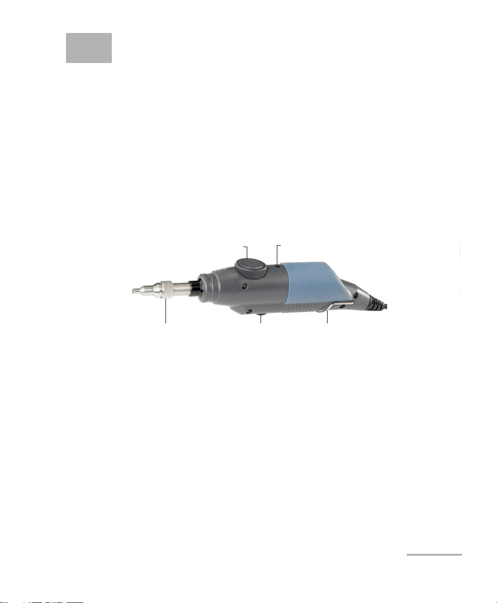
1 Introducing the FIP-400 Fiber
Focus knob
Retaining nut
Magnification button
(optional)
Fold out clip
Freeze/capture button
Inspection Probe and
ConnectorMax
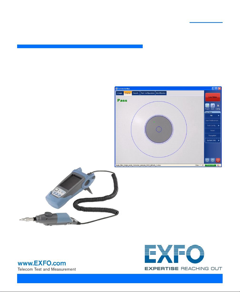
The FIP-400 Fiber Inspection Probe is a portable video microscope used to
inspect fiber ends. Unlike traditional microscopes, the FIP-400 facilitates
the examination of patchcord connectors and also hard-to-reach
connectors on the back of patch panels and bulkhead adapters.
Probe
The FIP-400 is designed to be an intuitive, easy-to-use piece of equipment.
This video microscope is used for inspecting fiber ends.
The focus knob can be turned in either direction to focus the image.
The magnification button allows you to shift between two levels of
magnification.
The freeze/capture button is used together with the EXFO USB adapter
and your unit or computer. It allows you to capture an image, perform
an analysis, save a file or return to the Live video mode.
The retaining nut holds tips securely in place, ensuring they are always
fastened in the correct position.
The fold out clip at the back of the probe allows you to hang the probe
when you are not using it.
The probe comes equipped with a protective cap that fits over basic tips;
therefore, you do not need to remove the tip before putting the cap on.
Fiber Inspection Probe 1
Page 8

Introducing the FIP-400 Fiber Inspection Probe and ConnectorMax
Probe Tips
Probe Tips
The FIP-400 comes with two interchangeable tips but other models are
also available.
The tips included with the Fiber Inspection Probe are used to inspect flat
polish (PC) 2.5 mm connectors. One tip is for inspecting patchcords
(pigtails, male connectors) for SC, FC, and ST connectors. The other tip is
for examining SC and FC bulkhead adapters or patch panel adapters
(female).
Other tip models are available for various bulkhead adapters and
patchcord connectors including multifiber types. For more information
about tips and their use, see Fiber Inspection Probe Tip Compatibility Chart
on page 65, or visit the EXFO Web site.
2 FIP-400
Page 9
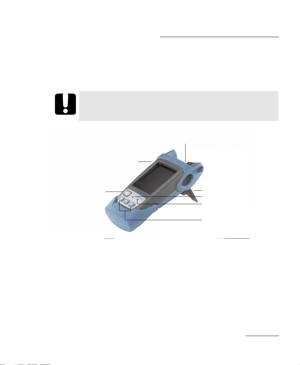
Introducing the FIP-400 Fiber Inspection Probe and ConnectorMax
On/Off button
AC charger/adapter connector
(indoor use only)
Probe connector
Contrast and
brightness keys
Battery status LED
Operation status LED
Stand
FIP Viewer (Optional)
FIP Viewer (Optional)
You can use the FIP Viewer with your Fiber Inspection Probe to inspect a
fiber end. The unit operates with an AC charger/adapter or a
lithium-ion battery.
IMPORTANT
The FIP Viewer is a standalone unit and does not work with
ConnectorMax.
Fiber Inspection Probe 3
Page 10
Introducing the FIP-400 Fiber Inspection Probe and ConnectorMax
FIP Viewer (Optional)
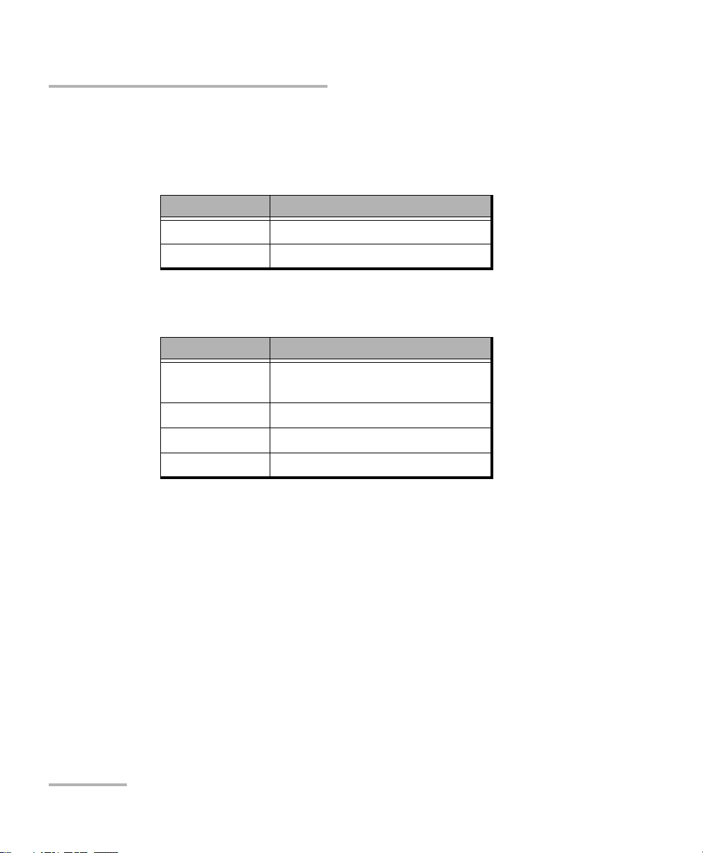
The two LEDs located on the front of the FIP Viewer provides you with the
status of your unit.
Operation status LED
LED Status
Green Probe connected
Flashing red Probe not connected
Battery status LED
LED Status
Green Full battery and AC
charger/adapter connected
Flashing green Charging battery
Yellow Low battery
Red Battery error
Note: If the battery is not full, the AC charger/adapter can support the operation
and charge the battery at the same time.
4 FIP-400
Page 11
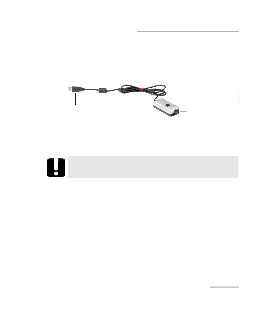
Introducing the FIP-400 Fiber Inspection Probe and ConnectorMax
Probe connector
USB connector
Capture button
Operation status LED
USB Adapter (Optional)
USB Adapter (Optional)
The USB adapter is used to connect the probe to a computer not equipped
with a 8-pin connector. It allows you to view probe images on your
computer screen. You can also capture and store these images on your
computer to document your work.
The Capture button on the USB adapter serves the same function as
the capture button on the probe.
The Status LED on the USB adapter will be green when the probe, USB
adapter, and computer are connected and the software is running.
IMPORTANT
The product supports USB 2.0 only. You cannot use it with USB 1.1.
Fiber Inspection Probe 5
Page 12
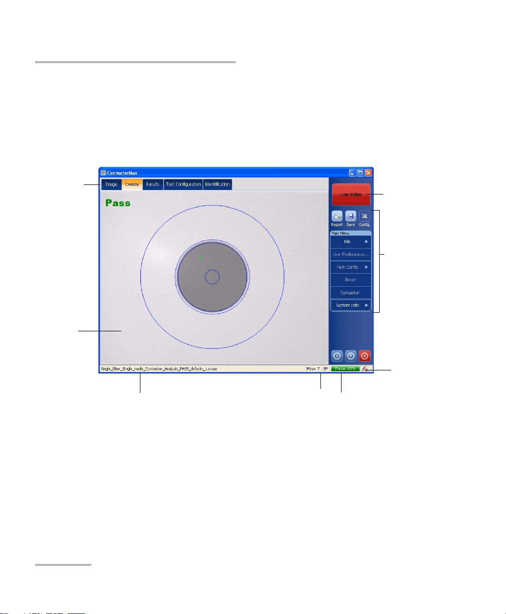
Introducing the FIP-400 Fiber Inspection Probe and ConnectorMax
Button bar
Viewing
area
File name preview (Capture
mode) or current test
configuration (Live mode)
Current (Capture
mode) or next (Live
mode) fiber index
Focus indicator
Probe
connection
status
Inspection
and analysis
tabs
Capture/Live
mode
button
ConnectorMax Software
ConnectorMax Software
ConnectorMax is the application used to view the fiber inspections. If you
have purchased the corresponding option, you can also use specific test
configurations and analyze the fibers automatically upon capturing a
picture.
6 FIP-400
Page 13
Introducing the FIP-400 Fiber Inspection Probe and ConnectorMax
Conventions
Conventions
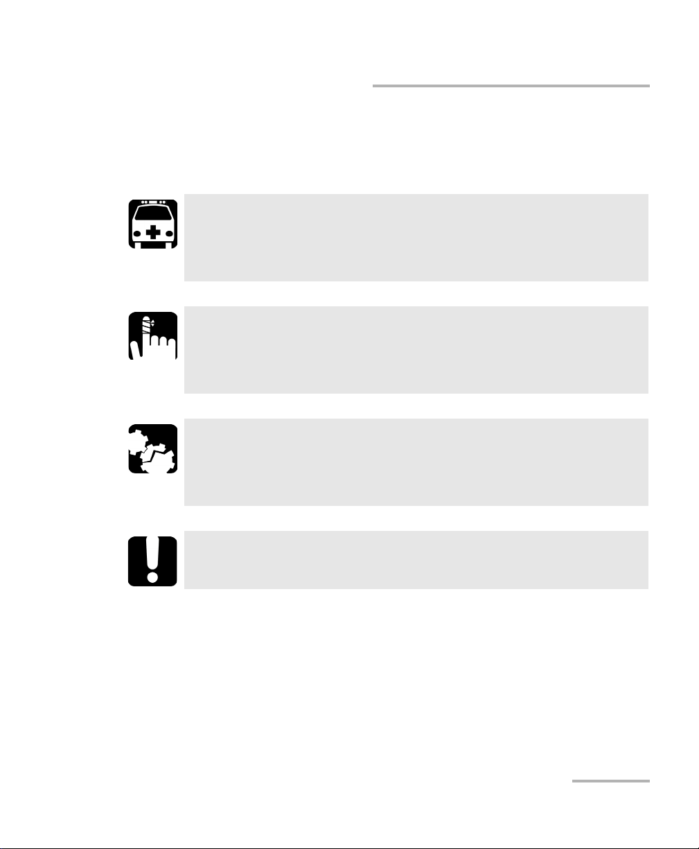
Before using the product described in this guide, you should understand
the following conventions:
WARNING
Indicates a potentially hazardous situation which, if not avoided,
could result in death or serious injury. Do not proceed unless you
understand and meet the required conditions.
CAUTION
Indicates a potentially hazardous situation which, if not avoided,
may result in minor or moderate injury. Do not proceed unless you
understand and meet the required conditions.
CAUTION
Indicates a potentially hazardous situation which, if not avoided,
may result in component damage. Do not proceed unless you
understand and meet the required conditions.
IMPORTANT
Refers to information about this product you should not overlook.
Note: The screen shots found in this user guide were made on a computer
running Microsoft Windows XP. The appearance of the application may
vary for other operating systems and platforms.
Fiber Inspection Probe 7
Page 14

Page 15
2 Safety Information
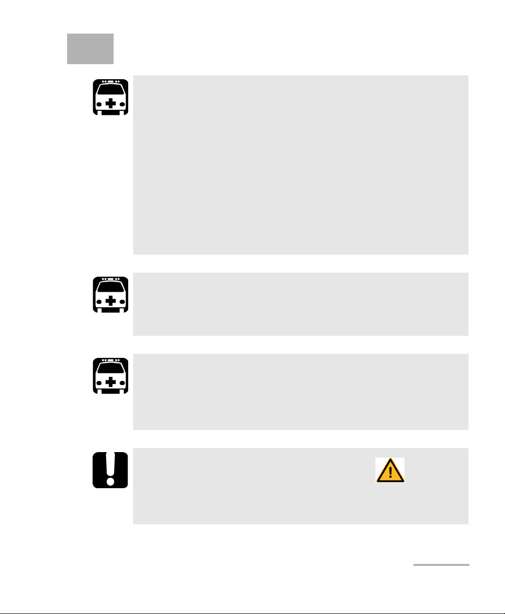
WARNING
Use only the listed and certified AC adapter/charger provided by
EXFO with your unit. It provides reinforced insulation between
primary and secondary, and is suitably rated for the country
where the unit is sold.
Use only accessories (such as the car outlet adapter, batteries,
and fiber inspection probe) designed for your unit and
approved by EXFO. For a complete list of accessories available
for your unit, refer to its technical specifications.
When you use the unit outdoors, ensure that it is protected
from liquids, dust, direct sunlight, precipitation, and full wind
pressure.
WARNING
Do not install or terminate fibers while a light source is active.
Never look directly into a live fiber and ensure that your eyes are
protected at all times.
WARNING
The use of controls, adjustments and procedures, namely for
operation and maintenance, other than those specified herein may
result in hazardous radiation exposure or impair the protection
provided by this unit.
IMPORTANT
When you see the following symbol on your unit , make sure
that you refer to the instructions provided in your user
documentation. Ensure that you understand and meet the required
conditions before using your product.
Fiber Inspection Probe 9
Page 16

Safety Information
Other safety instructions relevant for your product are located
throughout this documentation, depending on the action to
perform. Make sure to read them carefully when they apply to your
situation.
EXFO guarantees the specifications and viability of the products
ONLY if they are used with chargers and batteries provided by
EXFO.
IMPORTANT
CAUTION
10 FIP-400
Page 17
Safety Information
Other Safety Symbols on Your Unit
Other Safety Symbols on Your Unit
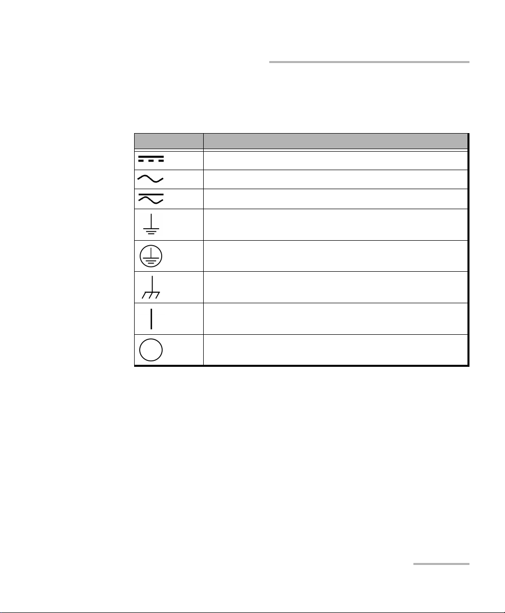
One or more of the following symbols may also appear on your unit.
Symbol Meaning
Direct current
Alternating current
Both direct and alternating current
The unit is equipped with an earth (ground) terminal.
The unit is equipped with a protective conductor terminal.
The unit is equipped with a frame or chassis terminal.
On (Power)
Off (Power)
Electrical Safety Information
If you need to ensure that the unit is completely turned off, disconnect the
power cable and remove the battery.
Fiber Inspection Probe 11
Page 18
Safety Information
Electrical Safety Information
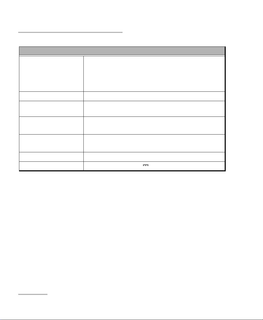
Equipment Ratings
Tem pe ra tu re
Operation
Storage
Battery operated: -10 °C to 50 °C (14 °F to 122 °F)
Charge mode: -10 °C to 40 °C (14 °F to 120 °F)
-40 °C to 70 °C (-40 °F to 158 °F)
Relative humidity unit: 95 % non-condensing
Maximum operation
2000 m (6562 ft)
altitude
Pollution degree
2 (unit connected to external power supply)
3 (unit operated from batteries)
b
a
Overvoltage category unit: I
AC adapter: II
Measurement category Not rated for measurement categories II, III or IV
Power supply rating 9V; 1A
a. Use the external power supply indoors only.
b. Equipment should be normally protected against exposure to direct sunlight, precipitations and full wind
pressure.
12 FIP-400
Page 19
3 Setting up Your Fiber
Inspection Probe and
ConnectorMax
You can change various settings in ConnectorMax such as the brightness
and contrast levels, default storage location, or automated file name. These
settings are stored for each user and kept for future work sessions.
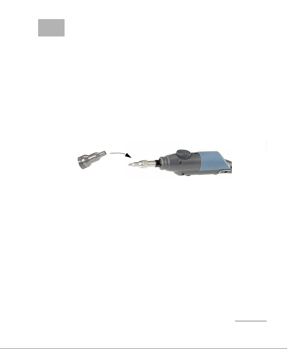
Changing the Fiber Inspection Probe Tip
You can use various tips depending on the type of connector you are
inspecting. For more information about tips you can use, visit the EXFO
Web site at www.exfo.com.
To change a tip:
1. Untighten the tip’s retaining nut.
2. Remove the tip.
3. Insert a new tip.
4. Adjust the tip to the notch.
5. Retighten the retaining nut.
Fiber Inspection Probe 13
Page 20
Setting up Your Fiber Inspection Probe and ConnectorMax
Adjusting Brightness and Contrast
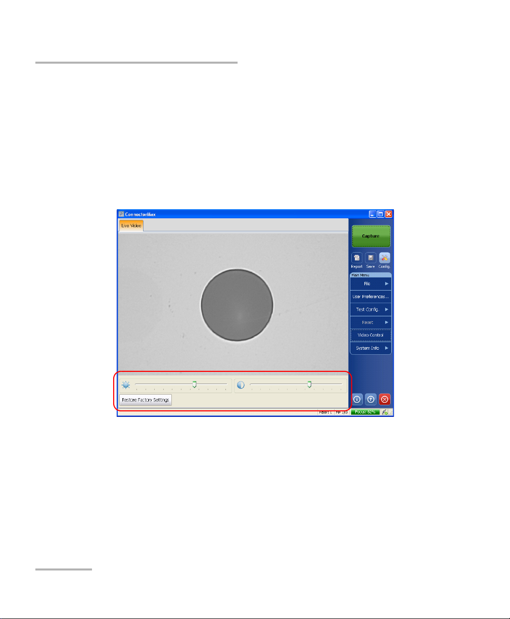
Adjusting Brightness and Contrast
Once the probe is connected to a fiber, you can adjust brightness and
contrast in order to better view the fiber under inspection.
To adjust brightness or contrast:
1. From the main window, click Video Control.
2. Use the contrast and brightness sliders at the bottom of the viewing
area to set the levels to suit your needs.
3. Click Video Control again to exit the menu. The menu will close by
itself after 10 seconds of inactivity.
14 FIP-400
Page 21
Setting up Your Fiber Inspection Probe and ConnectorMax
Selecting the Mode of Operation
Selecting the Mode of Operation
ConnectorMax can be used to inspect single-fiber (SF) and multiple-fiber
(MF) connectors. Depending on which mode of operation you select,
different options will be available.
Note: The multiple-fiber connector option is only available if you have purchased
this option.
Note: The mode of operation is kept in memory when you exit the application.
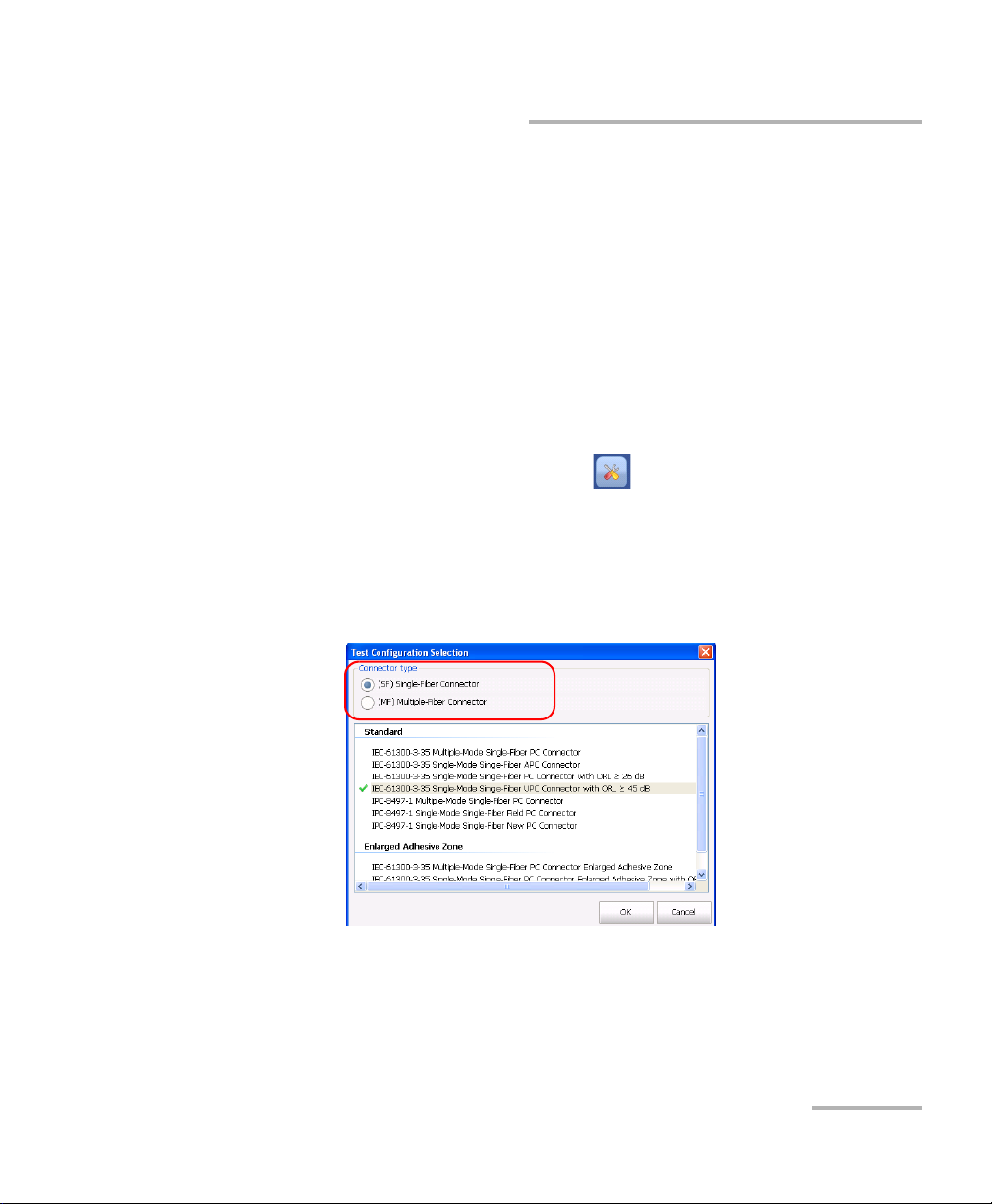
To select the mode of operation:
1. From the main window, click the button.
OR
Select the Test C onf i g . tab, then Select.
2. Select the connector type that suits your needs. The test configuration
selection window is automatically updated accordingly.
Fiber Inspection Probe 15
Page 22
Setting up Your Fiber Inspection Probe and ConnectorMax
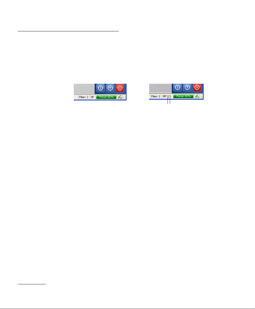
Single-Fiber Connector
Current fiber in
connector
Multiple-Fiber Connector
Number of fiber results
presently included in
connector result
Setting up Autonaming
3. If you are testing single-fiber connectors and have purchased the
analysis option, you can also select a test configuration at this point.
4. Click OK to close the window.
At the bottom of the main window, you can see what mode is currently
active.
Setting up Autonaming
The autonaming feature is useful to make a relevant naming scheme for
your tests. This also ensures that you do not overwrite files by mistake. You
can select which item goes in the file name, as well as the type of separator
you want to use in between.
A preview is available to show you the final output of the file name.
Note: When in multiple-fiber mode, the scheme is only editable prior to the first
acquisition; afterwards, it is available as read-only until you have
completed the inspection for the set number of fibers. If the Fiber ID item is
selected for the autonaming scheme, the file name will display both the
start and end fiber number values.
16 FIP-400
Page 23
Setting up Your Fiber Inspection Probe and ConnectorMax
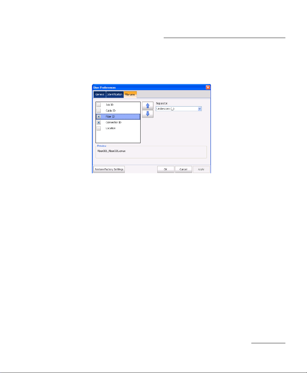
To set the autonaming scheme:
1. From the main window, select User Preferences.
2. Select the Filename tab.
Setting up Autonaming
Fiber Inspection Probe 17
Page 24
Setting up Your Fiber Inspection Probe and ConnectorMax
Setting up Autonaming
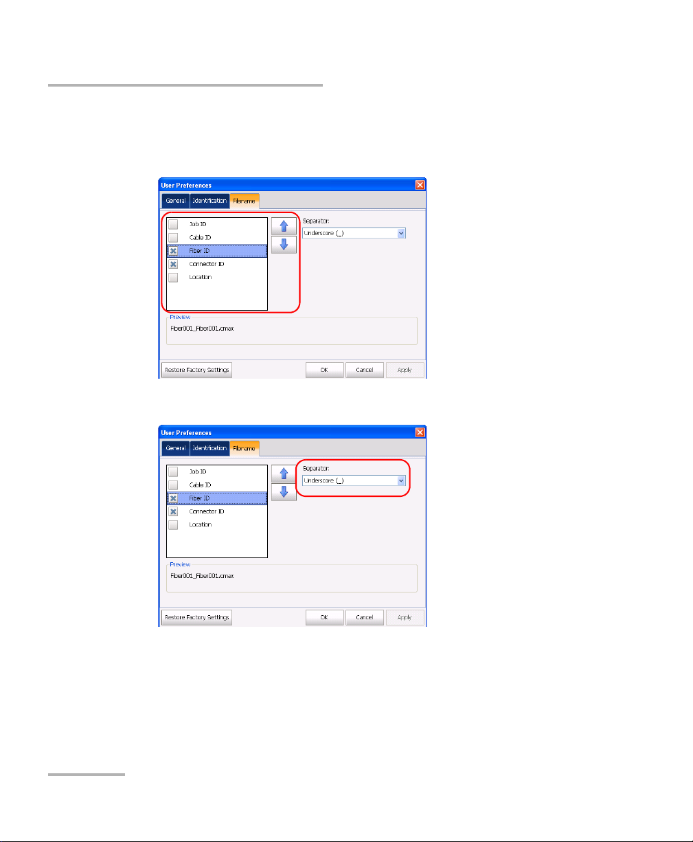
3. Select which items you want to include in the file name. The order of
the items in the name goes from top to bottom; use the up- and
down-arrow buttons to change the order.
4. Select a separator for the items in the list.
5. Click Apply to confirm your choice and continue working in the User
Preference window, or OK to confirm your choice and close the
window.
The new settings will apply the next time you perform a capture.
18 FIP-400
Page 25

Setting up Your Fiber Inspection Probe and ConnectorMax
Identifying Fibers
Identifying Fibers
ConnectorMax allows you to add information to your fiber inspection so
that your analysis is relevant and complete. Such information can be either
preset so that all of the analyses bear the same, or you can edit or add it
after the capture for a specific file.
Some of the items in the identification page can be customized to better
reflect your testing needs. However, as this is not directly part of the
application, you must change it manually. The items you can customize are
the following:
Cable ID.
Fiber ID.
Connector ID.
Location.
Note: Should you change the user interface language after modifying the items,
the latter will not be automatically translated; you will have to change the
items yourself into the new language.
Note: When in multiple-fiber mode, the information is only editable prior to the
first acquisition; afterwards, it is available as read-only until you have
completed the inspection for the set number of fibers. The information will
be the same for all of the fibers in the connector, except for the Fiber ID,
which will follow the connector currently tested.
Fiber Inspection Probe 19
Page 26

Setting up Your Fiber Inspection Probe and ConnectorMax
Identifying Fibers
To add information to the fibers:
1. From the main window, select User Preferences.
20 FIP-400
Page 27

Setting up Your Fiber Inspection Probe and ConnectorMax
Identifying Fibers
2. Select the Identification tab.
3. Fill out the boxes with the desired information. The identification will
increment the file name automatically using the step size you select.
In multiple-fiber connector mode, the start and stop values can be
used to indicate the number of fibers in the connector. The application
will prompt you to save the acquisition after you have reached the stop
number value.
4. Click Apply to confirm your choice and continue working in the User
Preference window, or OK to confirm your choice and close the
window.
Fiber Inspection Probe 21
Page 28

Setting up Your Fiber Inspection Probe and ConnectorMax
Identifying Fibers
To change fiber information once you have made a capture:
From the main window, select the Identification tab and enter the
information. The details that you have added from the User Preferences
window will already appear on-screen.
Note: In single-fiber connector mode, if you change items in the file name
identification, you will notice that the name at the bottom of the window is
automatically updated. This automated update is active until you save the
file and set the few file ID info.
Note: The analysis version and the capture platform are indicated at the bottom
of the tab.
22 FIP-400
Page 29

Setting up Your Fiber Inspection Probe and ConnectorMax
Identifying Fibers
To customize the identification items:
1. Depending on the unit onto which you are working, locate the
configuration file:
In Windows XP on a computer or on an FTB-500 platform:
C:\Documents and Settings\All Users\Application
Data\EXFO\ConnectorMax\Custom Fields.
On an FTB-1 or FTB-200 v2 unit: D:\Documents and Settings\All
Users\Application Data\EXFO\ConnectorMax\Custom Fields.
In Windows Vista and 7 on a computer:
C:\ProgramData\Exfo\ConnectorMax\Custom Fields
2. Open the file using a text editor that supports Unicode UTF-16
encoding.
3. Modify the four identifiers to reflect the desired changes. You can set
them to be visible or not as well.
The identifiers are limited to 15 characters. Special characters
(? / < > " : * | \) are not supported.
The identification item Fiber ID is set to have auto-increment attributes.
You can change the start, step and stop values as well. The start and
stop values must be a number between 1 and 999, and the step value
must be a number between -2 and 2.
Note: The text is case-sensitive and will appear as you write it on-screen.
4. Save and close the configuration file.
IMPORTANT
Make sure that the file is saved using a unicode UTF-16 encoding.
Otherwise, it will be considered as damaged or corrupt if it contains
accents or culture-specific characters.
The changes will be effective the next time you open ConnectorMax.
Fiber Inspection Probe 23
Page 30

Setting up Your Fiber Inspection Probe and ConnectorMax
Managing and Selecting Test Configurations (Optional)
To revert to the factory identification settings:
Delete the .xml configuration file.
Note: A new .xml file with the default settings will be created the next time you
start the application.
Managing and Selecting Test Configurations
(Optional)
If you have purchased the analysis portion of ConnectorMax, you can
create and select specific test configurations according to the type of fiber
you are analyzing, the connector type or the type of defect you are looking
for.
Note: If you have purchased the analysis option, some test configurations as per
IEC 61300-3-35 and IPC 8497-1 standards, and other configurations with an
enlarged C zone are available by default.
Creating custom test configurations is done through duplicating an existing
configuration, and then modifying the desired criteria.
If you create configurations on one unit or computer, and want to transfer
them to another unit or computer, you can do so. However, this feature is
not included directly in ConnectorMax, and you must proceed outside the
application.
24 FIP-400
Page 31

Setting up Your Fiber Inspection Probe and ConnectorMax
Managing and Selecting Test Configurations (Optional)
To select a test configuration:
1. From the main window, select Test C o nfi g , then Select.
OR
Click .
2. In the list of available test configurations, select the one you want to
use and click OK.
Fiber Inspection Probe 25
Page 32

Setting up Your Fiber Inspection Probe and ConnectorMax
Managing and Selecting Test Configurations (Optional)
To create a test configuration:
1. From the main window, select Test C o nfi g , then Manage.
2. Select the configuration that is the closest to the one you want to
create, then click Duplicate.
26 FIP-400
Page 33

Setting up Your Fiber Inspection Probe and ConnectorMax
Managing and Selecting Test Configurations (Optional)
3. In the General tab, modify the criteria as needed.
Configuration name: the application suggests a name for the
configuration. You can change it as needed (maximum 100
characters), but if you select a name that already exists, a suffix will
automatically be added so as not to overwrite files.
Connector type: select which type of connector you are using for
your inspection.
Fiber type: Select whether you are inspecting singlemode or
multimode fibers.
Pol i shing typ e: Select the type of polishing for the fibers between
APC, PC or UPC.
Analysis mode: Select the type of analysis between Outside plant
(selected by default) and Manufacturing. The manufacturing mode
is more sensitive for scratches and defects detection.
Cladding diameter: This value is set at 125 μm and cannot be
modified.
Fiber Inspection Probe 27
Page 34

Setting up Your Fiber Inspection Probe and ConnectorMax
Managing and Selecting Test Configurations (Optional)
4. Under the various layer tabs, indicate whether you want to be notified
of scratches, defects or both for each zone in the fiber, then set
thresholds for each item you select.
You can set up to 3 criteria per zone, and per anomaly type (scratches
or defects). The thresholds are divided into three categories:
Any: this enables the next criterion, which requires a specific
value.
1 to 10: the next criterion is automatically filled out to show the
infinity symbol ( ) and 0 as a threshold.
0: the criterion definition is complete.
Note: Zone C, as well as zone dimensions cannot be modified, as they are set as
per IEC and IPC recommendations.
5. Click Apply to confirm your choice and continue working in window,
or OK to confirm your choice and close the window.
28 FIP-400
Page 35

Setting up Your Fiber Inspection Probe and ConnectorMax
Managing and Selecting Test Configurations (Optional)
To edit a test configuration:
1. From the main window, select Test C o nfi g , then Manage.
2. Select the configuration you want to edit, then click Modify.
Note: You cannot edit standard or enlarged adhesive zone configurations.
3. Change the criteria as required. For details, see the section on creating
a test configuration.
Fiber Inspection Probe 29
Page 36

Setting up Your Fiber Inspection Probe and ConnectorMax
Managing and Selecting Test Configurations (Optional)
To delete a test configuration:
1. From the main window, select Test C o nfi g , then Manage.
2. Select the configuration you want to remove, then click Delete.
Note: You cannot delete standard or enlarged adhesive zone configurations.
30 FIP-400
Page 37

Setting up Your Fiber Inspection Probe and ConnectorMax
Reverting to Factory Settings
To transfer test configurations from one unit or computer to
another:
1. Using Windows Explorer, on the unit where the custom configurations
are located, select which files you want to transfer. The files are
located in different folders depending on the unit you are using.
In Windows XP on a computer, or on an FTB-500 platform:
C:\Documents and Settings\All Users\Application
Data\EXFO\ConnectorMax\Test configuration files\Custom.
In Windows Vista or 7 on a computer: C:\ProgramData\Exfo\
ConnectorMax\Test configuration files\Custom.
On an FTB-1 or FTB-200 v2 unit: D:\Documents and Settings\All
Users\Application Data\EXFO\ConnectorMax\Test configuration
files\Custom.
2. If the two units are linked through a network and that you have access,
you can paste the files directly into the corresponding folder of the
destination unit. Otherwise, copy the files onto a USB key, then paste
the files in the destination folder once you have.
Reverting to Factory Settings
At any time in the application, you can revert to factory settings in your
menus. However, the Restore Factory Settings button is valid only for the
window or tab where you use it.
Fiber Inspection Probe 31
Page 38

Page 39

4 Inspecting Fiber Ends
Viewing the fiber inspection is done using ConnectorMax. You can start the
application before or after connecting the probe, and the view on-screen
will be automatically updated.
To start the application:
On a computer, double-click the ConnectorMax icon on your desktop
or select Start > Programs > EXFO > ConnectorMax.
On an FTB-500, from the main window, select the Fiber Inspection
Probe function tab, or under the Applications tab, select
ConnectorMax. You can also use the direct Windows shortcut
Start > Programs > EXFO > Programs > ConnectorMax.
On an FTB-200 v2, select the Probe button in the Compact ToolBox
main window.
On an FTB-1, from the main window, select the Probe button, or under
the Utilities tab, select ConnectorMax. You can also use the direct
Windows shortcut
Start > Programs > EXFO > Programs > ConnectorMax.
The fiber under test appears on-screen.
Note: The screen size will adapt automatically to the unit you are using.
To exit the application:
1. Click .
OR
2. From the File menu, select Exit.
WARNING
Never look directly into a live fiber. It could cause serious eye
damage. Always use your FIP-400 Fiber Inspection Probe.
Fiber Inspection Probe 33
Page 40

Inspecting Fiber Ends
Inspecting Fiber Ends with the FIP Viewer
Inspecting Fiber Ends with the FIP Viewer
You can connect the Fiber Inspection Probe to the FIP Viewer to view and
inspect fiber ends.
Never look directly into a live fiber. It could cause serious eye
damage. Always use your FIP-400 Fiber Inspection Probe.
The battery in the FIP Viewer must be fully charged before the first
use. For more information, see Charging the Battery in The FIP
Viewer on page 52.
To inspect fiber ends:
1. Install a probe tip (see Changing the Fiber Inspection Probe Tip on
page 13).
WARNING
IMPORTANT
2. Insert the fiber into the probe tip.
3. Connect the probe to the FIP Viewer.
4. Press the On/Off button for approximately 2 seconds to turn on the FIP
Viewer.
5. Adjust the image to have the best view of the fiber end.
6. If the fiber end is dirty, remove it from the probe, clean it and
reinspect it.
7. Once you are satisfied with the inspection, go to the next fiber or turn
off the FIP Viewer.
34 FIP-400
Page 41

Inspecting Fiber Ends
Inspecting Fiber Ends with ConnectorMax
Inspecting Fiber Ends with ConnectorMax
When you connect the Fiber Inspection Probe to your unit (or computer via
a USB adapter) you can view and inspect fiber ends right away. This direct
viewing mode is known as the Live mode.
To inspect fiber ends in live mode:
1. Install a probe tip (see Changing the Fiber Inspection Probe Tip on
page 13).
2. Insert the fiber into the probe tip.
3. Connect your Fiber Inspection Probe to the USB video adapter, and
then connect the USB video adapter to your unit.
4. Start ConnectorMax if it is not already started.
5. Adjust the image focus to have the best view of the fiber end.
6. If the fiber end is dirty, remove it from the probe, clean it and
reinspect it.
7. Once you are satisfied with the inspection, go to the next fiber or turn
off the unit.
Fiber Inspection Probe 35
Page 42
Inspecting Fiber Ends
Capturing Images
Capturing Images
You can capture images of your inspections to include in reports, or save
them for future analyses. This is known as the Capture mode.
Note: Capturing an image with the dongle or the probe handset button
automatically brings ConnectorMax at the front of the screen if you have
more than one application running on your unit or computer.
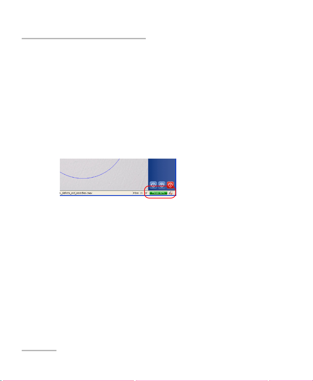
The focus indicator in the status bar indicates whether the current view is
optimized for a capture. A green indicator shows a picture that can be
captured and analyzed. Analysis will be more difficult with a yellow
indicator, and impossible with a red indicator.
To capture an image of the fiber under inspection:
From the main window, when in high magnification level, press Capture.
OR
Press the Fiber Inspection Probe handset button
OR
If you are capturing the acquisition from a computer, press the button on
the dongle located between the probe and the computer.
In single-fiber connector mode, if the autosaving features are enabled, your
capture is stored in the default folder. If not, you will be prompted to save
the acquisition before you go to the next one.
36 FIP-400
Page 43

Inspecting Fiber Ends
Capturing Images
In multiple-fiber connector mode, continue capturing files until you have
reached the number set in the user preferences. At the end of the capture,
you will be prompted to save your file. You can also save the file at any
time, even if you have not reached the maximum incremental value set.
While capturing the files, you can browse through the acquisitions you
have made. You will notice that the Video Control button becomes a
Navigation button.
To browse through the multiple-fiber connector acquisitions:
1. From the main window, click the Navigation button.
2. Use the arrow buttons to browse through the acquired files, or use the
drop-down menu to go directly to a specific acquisition.
Fiber Inspection Probe 37
Page 44

Inspecting Fiber Ends
Retesting a Fiber
Retesting a Fiber
Sometimes, a capture will show a fail status, but it could only be because
the fiber is dirty and you want to clean it and test it again. However, if you
have saved the file, the next capture you take will be incremented instead
of replacing the current file.
In order to avoid this incrementation and end up with unwanted files, you
can test a fiber again.
In single-fiber connector mode, retesting a fiber is only possible on the
most recent capture. In multiple-fiber connector mode, you can reset a
specific fiber within the capture, or reset the whole connector.
To retest a fiber:
1. After the capture, return to the Live mode.
2. From the main window, click Reset.
3. If you are in multiple-fiber mode, select whether you want to reset a
specific fiber, or the whole connector. If you reset a specific fiber,
select it in the provided list.
4. Capture the file again.
Note: The reset function will only become available again in the main window
once you save your file (single-fiber test mode only).
38 FIP-400
Page 45

Inspecting Fiber Ends
Saving Files
Saving Files
In capture mode, you can save the acquisition files manually for future
reference.
If you have purchased the analysis option you can also set ConnectorMax
so that it saves the capture automatically regardless of the result, or
automatically when the result is Pass only.
Note: When you return to the live mode, your file name structure will be
automatically incremented so that you do not overwrite your work.
Note: In multiple-fiber connector mode, the option is set automatically to Manual
and you cannot change it.
To save files automatically or automatically when the status is set
to Pass:
1. From the main window, select User Preferences.
2. Select the General tab.
3. Select whether you want the capture to be automatically saved
regardless of the result, saved if the result of the analysis is pass, or
select the manual save option if you only want to save specific files.
4. If you want to change the default location where the files will be saved,
you can do so by using the button.
5. Click Apply to confirm your choice and continue working in the
window, or OK to confirm your choice and close the window.
Fiber Inspection Probe 39
Page 46
Inspecting Fiber Ends
Saving Files
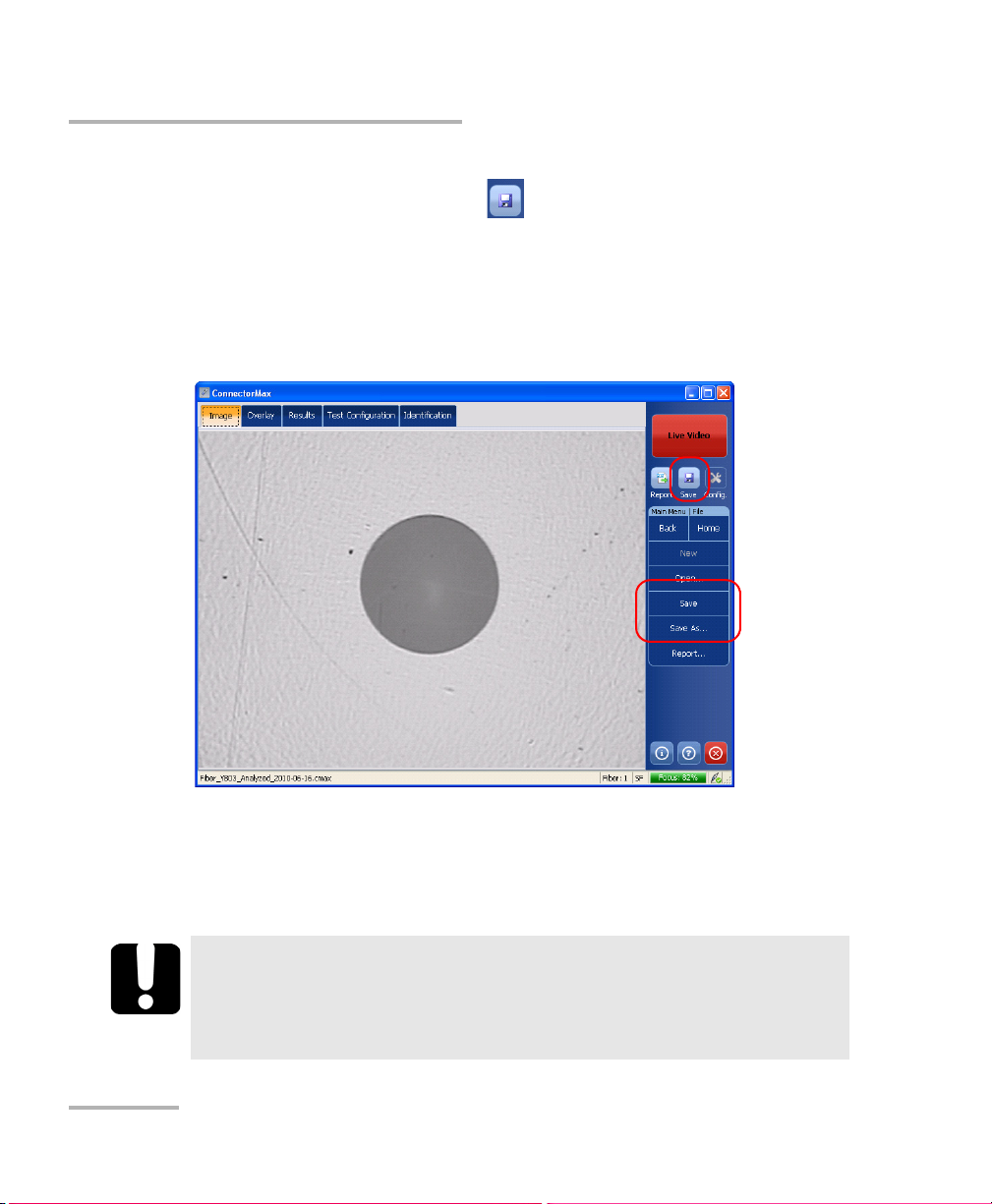
To s av e a f il e:
From the main window, click the button.
OR
Select the File menu, then Save to overwrite an existing file.
OR
Select the File menu, then Save As to change the file name or location.
Note: If you change the location for saving the files, this location will remain as
the default location for the remainder of the work session, or until you
change the location again.
IMPORTANT
If you have enabled the Generate report on save option, the new
report file will automatically overwrite the old one without
notifying you.
40 FIP-400
Page 47

Inspecting Fiber Ends
Opening and Closing Files
Opening and Closing Files
You can open captured files directly from the application to view them.
You can either open current .cmax files, or a legacy image file taken from a
previous fiber inspection.
Note: The accepted image formats for legacy files are .bmp, .jpg and .gif.
Note: Sample files for both single-fiber and multiple-fiber test modes are
available under the folder where ConnectorMax was installed, under a
folder named UserSamples.
To o pe n a f il e:
1. From the main window, select File, and then Open.
2. Select the desired file, and then click Open.
If you are opening a multiple-fiber connector file, you can browse through
the individual files using the Navigation button.
Note: If you are in a file browser, you can also double-click on the file to open it in
ConnectorMax. Double-clicking on a legacy file will open the application
currently associated with this file format.
Fiber Inspection Probe 41
Page 48

Inspecting Fiber Ends
Analyzing Captures (Optional, Single-Fiber Connector Mode Only)
Analyzing Captures (Optional, Single-Fiber
Connector Mode Only)
If you have acquired the capture analysis tool, it will be available in
ConnectorMax for you to perform automated pass/fail analyses according
to the criteria you have set.
The analysis option enables all of the tabs in the viewing area, whereas the
inspection-only option only enables the Image and Identification tabs.
Note: On units that allow it (FTB-500, FTB-200 v2), you will notice that the
Pass/Fail LED will indicate the analysis result as you capture files.
To enable the analysis tool:
1. From the main window, select User Preferences.
2. Under the General tab, select Analyze on capture.
42 FIP-400
Page 49

Inspecting Fiber Ends
Analyzing Captures (Optional, Single-Fiber Connector Mode Only)
3. Select whether you want the analysis to be automatically saved if the
result of the analysis is pass, or select the manual save option if you
only want to save specific analyses.
Note: The automated save option is only available if you have purchased the
analysis option. If you only have the inspection option, the save option is
automatically set to manual.
4. Click Apply to confirm your choice and continue working in the
window, or OK to confirm your choice and close the window.
Fiber Inspection Probe 43
Page 50

Inspecting Fiber Ends
Analyzing Captures (Optional, Single-Fiber Connector Mode Only)
Once the analysis option is activated, you will notice that when you capture
a fiber image, all of the tabs in the viewing area will be available with
information about the results. This information is read-only, except for the
Information tab, and shows you the details you would see in the
corresponding report, if you choose to make one.
The Image tab shows the snapshot of the fiber when you captured it.
You can see some anomalies right away, but no analysis is performed.
44 FIP-400
Page 51

Inspecting Fiber Ends
Analyzing Captures (Optional, Single-Fiber Connector Mode Only)
The Overlay tab shows the status of the analysis, the analysis zones,
and any anomalies (defects, scratches) found on the fiber endface.
Fiber Inspection Probe 45
Page 52

Inspecting Fiber Ends
Analyzing Captures (Optional, Single-Fiber Connector Mode Only)
The Results tab shows detailed information for scratches and defects
detected in each test zone and the corresponding test status.
46 FIP-400
Page 53

Inspecting Fiber Ends
Analyzing Captures (Optional, Single-Fiber Connector Mode Only)
The Test Configuration tab shows the detail of the test configuration
you had selected to perform this analysis.
Fiber Inspection Probe 47
Page 54

Inspecting Fiber Ends
Creating Reports
Creating Reports
You can create a report based on the current inspection and analysis
results (single fiber mode only). This report is saved as an html, or mhtml
file, depending on the format you select.
The html report separates the text from the graphical elements and
puts them in the folder separately.
The mhtml report gathers all of the graphical elements and report
text into one file.
Note: The mhtml format is automatically supported in Microsoft Internet Explorer
version 6 and later. You could need to install a plugin to view this format in
other types of browsers.
Note: The report creation is available only in Capture mode.
If you have selected the Generate report on save option, a report is
automatically created when you save your capture.
48 FIP-400
Page 55

Inspecting Fiber Ends
Creating Reports
To activate automated report creation:
1. From the main window, select User Preferences.
2. Under the General tab, select Generate report on save.
3. Select the type of report you want.
4. If you want to change the default location where the reports will be
saved, you can do so by using the button.
5. Click Apply to confirm your choice and continue working in the
window, or OK to confirm your choice and close the window.
Fiber Inspection Probe 49
Page 56

Inspecting Fiber Ends
Creating Reports
To create a report manually:
1. From the main window, click .
OR
Select the File menu, then Report.
2. Select the type of report you want to create, and the location for the
report.
3. Click Save to close the window.
You can now open the report in any Internet browser from the location
where the file was saved.
50 FIP-400
Page 57

5 Maintenance
General Maintenance
To help ensure long, trouble-free operation:
Keep the unit free of dust.
Clean the unit casing and front panel with a cloth slightly dampened
with water.
Store unit at room temperature in a clean and dry area. Keep the unit
out of direct sunlight.
Avoid high humidity or significant temperature fluctuations.
Avoid unnecessary shocks and vibrations.
If any liquids are spilled on or into the unit, turn off the power
immediately and let the unit dry completely.
The use of controls, adjustments and procedures other than those
specified herein may result in exposure to hazardous situations or
impair the protection provided by this unit.
WARNING
Fiber Inspection Probe 51
Page 58

Maintenance
Charging the Battery in The FIP Viewer
Charging the Battery in The FIP Viewer
The new battery in the FIP Viewer must be fully charged before first use.
To charge the battery:
Connect the AC charger/adapter to the FIP Viewer.
Normal charging time is about 4 hours.
Note: The FIP Viewer may be used on AC charger/adapter while the batteries are
charging.
Replacing Batteries
Your unit uses batteries with built-in protection that have been especially
designed for EXFO. For this reason, you can only replace the main battery
with a battery designed for your FIP-400.
You can purchase new batteries and empty battery compartments (also
known as “battery covers”) from EXFO.
WARNING
There is a risk of explosion if you do not use the appropriate
battery.
CAUTION
Use Li-Ion batteries of the same type and model only. Use of other
batteries may damage the unit and compromise your safety.
52 FIP-400
Page 59

Maintenance
Recycling and Disposal (Applies to European Union Only)
To replace the battery:
1. Acquire a new battery from EXFO.
2. Turn off the unit (if the AC adapter is plugged in, you may replace the
battery while unit is on).
3. Open the battery compartment door located at the back of the unit.
4. Replace the battery, respecting the polarity.
5. Close the battery compartment door.
WARNING
Do not throw batteries into fire or water and do not short-circuit
the batteries’ electrical contacts. Do not disassemble.
Recycling and Disposal
(Applies to European Union Only)
For complete recycling/disposal information as per European Directive
WEEE 2012/19/UE, visit the EXFO Web site at www.exfo.com/recycle.
Fiber Inspection Probe 53
Page 60

Page 61

6 Troubleshooting
Solving Common Problems
The table below presents common problems and their solutions.
Problem Solution
I cannot analyze an
image
The analysis was
interrupted before it
was complete
I cannot see the fiber
on-screen
The image is not focused properly; use the focus knob on
the probe until the focus indicator displays the best value
available. Yellow indicates an acceptable range, and green
shows the preferred range.
Ensure that the probe is connected properly.
Ensure that the connector is aligned properly.
Ensure that the focus value is sufficient to perform the
analysis.
Ensure that the contrast and brightness values are
appropriate in the capture.
Ensure that you are using a high magnitude level.
Turn the probe on
Verify the probe connection status to see if ConnectorMax
is detecting the probe properly. If the probe is connected
properly, close ConnectorMax and open it again.
If you are using a USB adapter and the probe status is
green, ensure that the probe is connected properly to the
adapter. ConnectorMax will only function with the USB 2.0
dongle.
Fiber Inspection Probe 55
Page 62

Troubleshooting
Contacting the Technical Support Group
Contacting the Technical Support Group
To obtain after-sales service or technical support for this product, contact
EXFO at one of the following numbers. The Technical Support Group is
available to take your calls from Monday to Friday, 8:00 a.m. to 7:00 p.m.
(Eastern Time in North America).
Technical Support Group
400 Godin Avenue
Quebec (Quebec) G1M 2K2
CANADA
For detailed information about technical support, and for a list of other
worldwide locations, visit the EXFO Web site at www.exfo.com.
If you have comments or suggestions about this user documentation, you
can send them to customer.feedback.manual@exfo.com.
To accelerate the process, please have information such as the name and
the serial number (see the product identification label), as well as a
description of your problem, close at hand.
1 866 683-0155 (USA and Canada)
Tel.: 1 418 683-5498
Fax: 1 418 683-9224
support@exfo.com
56 FIP-400
Page 63

Troubleshooting
Viewing Information about ConnectorMax
Viewing Information about ConnectorMax
You can view information about ConnectorMax such as the version
number and contact information for technical support in the About
window.
To view ConnectorMax information:
On a computer, an FTB-500 or an FTB-1, from the main window, click
.
On an FTB-200 v2 Compact Modular Platform, select the System Info,
then About.
Viewing Online Help
You can view the online help for ConnectorMax at any time.
To view the online help:
From the main window, click .
OR
From the main window, select System Info, then Help.
Fiber Inspection Probe 57
Page 64

Troubleshooting
Transportation
Transportation
Maintain a temperature range within specifications when transporting the
unit. Transportation damage can occur from improper handling. The
following steps are recommended to minimize the possibility of damage:
Pack the unit in its original packing material when shipping.
Avoid high humidity or large temperature fluctuations.
Keep the unit out of direct sunlight.
Avoid unnecessary shocks and vibrations.
58 FIP-400
Page 65

7 Warranty
General Information
EXFO Inc. (EXFO) warrants this equipment against defects in material and
workmanship for a period of one year from the date of original shipment.
EXFO also warrants that this equipment will meet applicable specifications
under normal use.
During the warranty period, EXFO will, at its discretion, repair, replace,
or issue credit for any defective product, as well as verify and adjust the
product free of charge should the equipment need to be repaired or if the
original calibration is erroneous. If the equipment is sent back for
verification of calibration during the warranty period and found to meet all
published specifications, EXFO will charge standard calibration fees.
The warranty can become null and void if:
unit has been tampered with, repaired, or worked upon by
unauthorized individuals or non-EXFO personnel.
warranty sticker has been removed.
IMPORTANT
case screws, other than those specified in this guide, have been
removed.
case has been opened, other than as explained in this guide.
unit serial number has been altered, erased, or removed.
unit has been misused, neglected, or damaged by accident.
THIS WARRANTY IS IN LIEU OF ALL OTHER WARRANTIES EXPRESSED,
IMPLIED, OR STATUTORY, INCLUDING, BUT NOT LIMITED TO, THE
IMPLIED WARRANTIES OF MERCHANTABILITY AND FITNESS FOR A
PARTICULAR PURPOSE. IN NO EVENT SHALL EXFO BE LIABLE FOR
SPECIAL, INCIDENTAL, OR CONSEQUENTIAL DAMAGES.
Fiber Inspection Probe 59
Page 66

Warranty
Liability
Liability
EXFO shall not be liable for damages resulting from the use of the product,
nor shall be responsible for any failure in the performance of other items to
which the product is connected or the operation of any system of which
the product may be a part.
EXFO shall not be liable for damages resulting from improper usage or
unauthorized modification of the product, its accompanying accessories
and software.
Exclusions
EXFO reserves the right to make changes in the design or construction of
any of its products at any time without incurring obligation to make any
changes whatsoever on units purchased. Accessories, including but not
limited to fuses, pilot lamps, batteries and universal interfaces (EUI) used
with EXFO products are not covered by this warranty.
This warranty excludes failure resulting from: improper use or installation,
normal wear and tear, accident, abuse, neglect, fire, water, lightning or
other acts of nature, causes external to the product or other factors beyond
the control of EXFO.
IMPORTANT
In the case of products equipped with optical connectors, EXFO will
charge a fee for replacing connectors that were damaged due to
misuse or bad cleaning.
Certification
EXFO certifies that this equipment met its published specifications at the
time of shipment from the factory.
60 FIP-400
Page 67

Warranty
Service and Repairs
Service and Repairs
EXFO commits to providing product service and repair for five years
following the date of purchase.
To send any equipment for service or repair:
1. Call one of EXFO’s authorized service centers (see EXFO Service
Centers Worldwide on page 62). Support personnel will determine if
the equipment requires service, repair, or calibration.
2. If equipment must be returned to EXFO or an authorized service
center, support personnel will issue a Return Merchandise
Authorization (RMA) number and provide an address for return.
3. If possible, back up your data before sending the unit for repair.
4. Pack the equipment in its original shipping material. Be sure to include
a statement or report fully detailing the defect and the conditions under
which it was observed.
5. Return the equipment, prepaid, to the address given to you by support
personnel. Be sure to write the RMA number on the shipping slip. EXFO
will refuse and return any package that does not bear an RMA number.
Note: A test setup fee will apply to any returned unit that, after test, is found to
meet the applicable specifications.
After repair, the equipment will be returned with a repair report. If the
equipment is not under warranty, you will be invoiced for the cost
appearing on this report. EXFO will pay return-to-customer shipping costs
for equipment under warranty. Shipping insurance is at your expense.
Routine recalibration is not included in any of the warranty plans. Since
calibrations/verifications are not covered by the basic or extended
warranties, you may elect to purchase FlexCare Calibration/Verification
Packages for a definite period of time. Contact an authorized service center
(see EXFO Service Centers Worldwide on page 62).
Fiber Inspection Probe 61
Page 68

Warranty
EXFO Service Centers Worldwide
EXFO Service Centers Worldwide
If your product requires servicing, contact your nearest authorized service
center.
EXFO Headquarters Service Center
400 Godin Avenue
Quebec (Quebec) G1M 2K2
CANADA
EXFO Europe Service Center
Winchester House, School Lane
Chandlers Ford, Hampshire S053 4DG
ENGLAND
EXFO Telecom Equipment
(Shenzhen) Ltd.
3rd Floor, Building 10,
Yu Sheng Industrial Park (Gu Shu
Crossing), No. 467,
National Highway 107,
Xixiang, Bao An District,
Shenzhen, China, 518126
1 866 683-0155 (USA and Canada)
Tel.: 1 418 683-5498
Fax: 1 418 683-9224
support@exfo.com
Tel.: +44 2380 246800
Fax: +44 2380 246801
support.europe@exfo.com
Tel: +86 (755) 2955 3100
Fax: +86 (755) 2955 3101
support.asia@exfo.com
62 FIP-400
Page 69

A Technical Specifications
IMPORTANT
The following technical specifications can change without notice.
The information presented in this section is provided as a reference
only. To obtain this product’s most recent technical specifications,
visit the EXFO Web site at www.exfo.com.
Software
Fiber Inspection Probe 63
Page 70

Technical Specifications
Video Inspection Probe
Video Inspection Probe
Fiber Probe Viewer
USB Converter
64 FIP-400
Page 71

B Fiber Inspection Probe Tip
Compatibility Chart
The table below establishes the Fiber Inspection Probe tip compatibility
with the different fiber inspection and the analysis (option) modules
provided with the ConnectorMax application:
Tip Description Tip Code Inspection Analysis
Uni.1.25 mm tip for PC connector FIPT-400-U12M X X
LC tip for PC bulkhead adapter FIPT-400-LC X X
FC and SC APC tip for bulkhead adapter FIPT-400-FC-SC-APC X X
Uni.2.5 mm tip for APC connector FIPT-400-U25MA X X
Uni.1.25 mm tip for APC connector FIPT-400-U12MA X X
ST tip for UPC bulkhead adapter FIPT-400-ST X X
FC and SC tip for bulkhead adapter FIPT-400-FC-SC X X
Uni.2.5 mm tip for PC connector FIPT-400-U25M X X
Extended SC tip for PC bulkhead
adapter
MU tip for UPC bulkhead adapter FIPT-400-MU X X
E-2000 tip for PC bulkhead FIPT-400-E2000 X X
MU-L tip for UPC bulkhead adapter FIPT-400-MU-L X X
Tip for D4 bulkhead adapter FIPT-400-D4 X X
U20M2 tip for male ferule connector FIPT-400-U20M2 X X
LEMO tip for bulkhead adapter FIPT-400-LEMO X X
E-2000 tip for APC bulkhead adapter FIPT-400-E2000-APC X
OPTITAP tip for APC bulkhead adapter FIPT-400-OTAP-APC X
OPTITIP MT tip kit for APC bulkhead
adapter
Fiber Inspection Probe 65
FIPT-400-SC-L X X
FIPT-400-OTIP-MT-APC X
Page 72

Fiber Inspection Probe Tip Compatibility Chart
Tip Description Tip Code Inspection Analysis
OPTITIP MT tip for APC bulkhead
FIPT-400-OTIP-MT-APC/M X
adapter - male end
LC tip for APC bulkhead adapter TIP LC for APC bulkhead X
LC tip for bulkhead adapter 60 Degree
FIPT-400-LC-A6 X
Angled
LX5 tip for UPC bulkhead adapter FIPT-400-LX5 X
LX5 tip for APC bulkhead adapter FIPT-400-LX5-APC X
MTP/APC tip for bulkhead adapter -
FIPT-400-MTPA2 X
Extended & Improved
MTP2 tip for bulkhead adapter FIPT-400-MTP2 X
MTP2 component used with
FIPT-400-MTP2-TIP X
FIPT-400-MTP2 tip
MTPA component used with MTP2 tip FIPT-400-MTPA-TIP X
Bulkhead adapter FIPT-400-ADAPTER X
Tip for SMA bulkhead adapter FIPT-400-SMA X
Tip for SMA male connector FIPT-400-SMAM X
Tip for MTRJ bulkhead adapter FIPT-400-MTRJ X
Contact your vendor for additional information regarding the most recent
Fiber Inspection Probe tips that are not listed above.
66 FIP-400
Page 73

Index
Index
A
about window............................................. 57
after-sales service ........................................ 56
analysis tool ................................................ 42
application
exiting ................................................... 33
starting.................................................. 33
autonaming ................................................ 16
B
battery
charging ................................................ 52
status LED................................................ 4
brightness ................................................... 14
browsing, multiple-fiber acquisition............ 37
buttons, description ...................................... 6
C
capture mode.............................................. 36
caution
of personal hazard................................... 7
of product hazard.................................... 7
certification information ................................v
charging the battery ................................... 52
cleaning
front panel............................................. 51
closing application. ..................................... 33
configurations, test ..................................... 24
ConnectorMax
exiting ................................................... 33
introduction............................................. 6
starting.................................................. 33
contrast....................................................... 14
conventions, safety ....................................... 7
copying configuration to another unit ........ 31
creating reports........................................... 48
custom configurations, transferring ............ 31
customer service.......................................... 61
D
documentation............................................ 57
E
equipment returns....................................... 61
exiting application....................................... 33
F
factory settings............................................ 31
fiber to test.................................................. 15
fibers, identification .................................... 19
file naming .................................................. 16
files
legacy .................................................... 41
opening .................................................41
saving ....................................................39
FIP Viewer
buttons .................................................... 3
connector................................................. 3
LEDs ......................................................... 3
focus indicator............................................. 36
front panel, cleaning ................................... 51
H
help ............................................................. 57
html report.................................................. 48
I
identification label....................................... 56
identifying fibers .........................................19
image file
closing ...................................................41
opening .................................................41
Fiber Inspection Probe 67
Page 74

Index
information about ConnectorMax............... 57
inspecting fiber ends............................. 34, 35
inspection mode
capture .................................................. 36
live......................................................... 35
L
label, identification ..................................... 56
LED, battery status
flashing green.......................................... 3
flashing red ............................................. 3
green ....................................................... 3
yellow...................................................... 3
legacy picture files....................................... 41
live mode .................................................... 35
M
maintenance
front panel ............................................ 51
general information............................... 51
mhtml report .............................................. 48
mode of operation ...................................... 15
multifiber test ............................................. 15
N
naming files ................................................ 16
navigating, multiple-fiber acquisition.......... 37
O
online help .................................................. 57
opening files ............................................... 41
operation mode .......................................... 15
overlay tab .................................................. 45
P
probe
capture button ........................................ 1
focus knob............................................... 1
fold out clip ............................................. 1
magnification control button................... 1
protective cap .......................................... 1
retaining nut............................................ 1
product
identification label ................................. 56
specifications ......................................... 63
R
reports......................................................... 48
results tab ................................................... 46
return merchandise authorization (RMA) .... 61
S
safety
caution .................................................... 7
conventions .............................................7
warning ...................................................7
saving files................................................... 39
service and repairs....................................... 61
service centers ............................................. 62
setting
brightness.............................................. 14
contrast ................................................. 14
settings, factory........................................... 31
shipping to EXFO......................................... 61
single fiber test............................................ 15
specifications, product ................................63
starting application .....................................33
storage requirements ..................................51
storage, files................................................ 39
symbols, safety.............................................. 7
T
tabs
overlay ................................................... 45
results .................................................... 46
test configuration .................................. 47
technical specifications................................ 63
technical support......................................... 56
temperature for storage .............................. 51
68 FIP-400
Page 75

test configuration
tab......................................................... 47
transferring............................................ 31
test configurations, managing .................... 24
tips
changing ............................................... 13
types........................................................ 2
tool for analysis........................................... 42
transferring test configurations................... 31
transportation requirements ................. 51, 58
type of fiber ................................................ 15
U
USB
adapter.................................................... 5
connector ................................................ 5
V
video, image adjustment............................. 14
viewing fiber ends................................. 34, 35
Index
W
warranty
certification ........................................... 60
exclusions .............................................. 60
general .................................................. 59
liability................................................... 60
null and void.......................................... 59
Fiber Inspection Probe 69
Page 76

NOTICE
抩⛙
CHINESE REGULATION ON RESTRICTION OF HAZARDOUS SUBSTANCES
₼⦌␂ℝ☀⹂䓸德棟Ⓟ䤓屓⸩
NAMES AND CONTENTS OF THE TOXIC OR HAZARDOUS SUBSTANCES OR ELEMENTS
CONTAINED IN THIS EXFO PRODUCT
▔⚺⦷㦻 EXFO ℶ❐₼䤓㦘㹡㦘⹂䓸德㒥⏒侯䤓⚜䱿✛⚺摞
O
Indicates that this toxic or hazardous substance contained in all of the homogeneous
materials for this part is below the limit requirement in SJ/T11363-2006
嫷䯉年㦘㹡㦘⹂䓸德⦷年捷ↅ㓏㦘⧖德㧟㠨₼䤓⚺摞⧖⦷ SJ/T11363-2006 㪖屓⸩䤓
棟摞尐㻑ⅴₚᇭ
X
Indicates that this toxic or hazardous substance contained in at least one of the homogeneous
materials used for this part is above the limit requirement in SJ/T11363-2006
嫷䯉年㦘㹡㦘⹂䓸德咂⺠⦷年捷ↅ䤓㩟⧖德㧟㠨₼䤓⚺摞怔⒉ SJ/T11363-2006 㪖
屓⸩䤓棟摞尐㻑ᇭ
Part Name
捷ↅ⚜䱿
Toxic or hazardous Substances and Elements
㦘㹡㦘⹂䓸德✛⏒侯
Lead
杔
(Pb)
Mercury
㻭
(Hg)
Cadmium
椣
(Cd)
Hexavalent
Chromium
⏼ↆ杻
(Cr VI)
Pol yb ro mi na te d
biphenyls
⮩䅃勣啾
(PBB)
Polybrominated
diphenyl ethers
⮩䅃ℛ啾搩
(PBDE)
Enclosure
⮥⮂
OO O O O O
Electronic and
electrical
sub-assembly
䟄✛䟄兓ↅ
XO X O X X
Optical
sub-assembly
a
⏘ⷵ兓ↅ
a
a. If applicable.
Ⱁ㨫抑䞷ᇭ
XO O O O O
Mechanical
sub-assembly
a
㧉㬿兓ↅ
a
OO O O O O
Page 77

MARKING REQUIREMENTS
㪖㽷尐㻑
Product
ℶ❐
Environmental protection use period (years)
䘾⬒≬㔳∎䞷㦮棟 ( )
Logo
㪖㉦
This Exfo product
㦻 EXFO ℶ❐
10
Battery
a
䟄㻯
a
a. If applicable.
Ⱁ㨫抑䞷ᇭ
5
Page 78

P/N: 1065930
www.EXFO.com · info@exfo.com
CORPORATE HEADQUARTERS 400 Godin Avenue Quebec (Quebec) G1M 2K2 CANADA
Tel.: 1 418 683-0211 · Fax: 1 418 683-2170
EXFO AMERICA 3400 Waterview Parkway Suite 100 Richardson, TX 75080 USA
EXFO EUROPE Winchester House,
EXFO ASIA-PACIFIC 62 Ubi Road 1,
EXFO CHINA Beijing Global Trade Center, Tower C,
EXFO SERVICE ASSURANCE 270 Billerica Road Chelmsford MA, 01824 USA
EXFO FINLAND Elektroniikkatie 2 FI-90590 Oulu, FINLAND
TOLL-FREE (USA and Canada) 1 800 663-3936
© 2014 EXFO Inc. All rights reserved.
Printed in Canada (2014-01)
School Lane
#09-01/02 Oxley Bizhub 2
Room 1207, 36 North Third Ring Road
East, Dongcheng District
Tel.: 1 972-761-927 · Fax: 1 972-761-9067
Chandlers Ford, Hampshire S053 4DG ENGLAND
Tel.: +44 2380 246 800 · Fax: +44 2380 246 801
SINGAPORE 408734
Tel.: +6563338241 · Fax: +6563338242
Beijing 100013 P. R. CHINA
Tel.: +86 (10) 5825 7755 · Fax: +86 (10) 5825 7722
Tel.: 1 978 367-5600 · Fax: 1 978 367-5700
Tel.: +358 (0) 403 010 300 · Fax: +358 (0) 8 564 5203
 Loading...