

Page 1
FG-750
Fiber Guardian
User Guide
Page 2

Copyright Information
Copyright Information
Copyright © 2012–2015 EXFO Inc. All rights reserved. No part of this
publication may be reproduced, stored in a retrieval system or transmitted
in any form, be it electronically, mechanically, or by any other means such
as photocopying, recording or otherwise, without the prior written
permission of EXFO Inc. (EXFO).
Information provided by EXFO is believed to be accurate and reliable.
However, no responsibility is assumed by EXFO for its use nor for any
infringements of patents or other rights of third parties that may result from
its use. No license is granted by implication or otherwise under any patent
rights of EXFO.
EXFO’s Commerce And Government Entities (CAGE) code under the North
Atlantic Treaty Organization (NATO) is 0L8C3.
The information contained in this publication is subject to change without
notice.
Trademarks
EXFO’s trademarks have been identified as such. However, the presence
or absence of such identification does not affect the legal status of any
trademark.
Units of Measurement
Units of measurement in this publication conform to SI standards and
practices.
Patents
This product incorporates the proprietary EXFO Link-Aware™ technology,
employing spectrally-selective high-reflectance demarcation (HRD) filters
to enable the attenuation of a specific branch of a P2MP
(point-to-multipoint) network to be measured/monitored. The
Link-Aware™ technology is protected by Canadian patent no. 2,737,974, by
pending US patent application no. 13/124,455, and by corresponding
pending patent applications in Australia, China, the EC, India, Japan, and
Korea.
ii FG-750
Page 3

Version number: 2.0.1
Copyright Information
Fiber Guardian iii
Page 4

Copyright Information
Microsoft End-User License Agreement
You have acquired a device ("DEVICE") that includes software licensed by EXFO Inc. (EXFO) from an affiliate of Microsoft
Corporation ("MS"). Those installed software products of MS origin, as well as associated media, printed materials, and
"online" or electronic documentation ("SOFTWARE") are protected by international intellectual property laws and treaties.
Manufacturer, MS and its suppliers (including Microsoft Corporation) own the title, copyright, and other intellectual property
rights in the SOFTWARE. The SOFTWARE is licensed, not sold. All rights reserved. The Microsoft EULA for the SOFTWARE can
be found at: http://www.microsoft.com/en-us/legal/intellectualproperty/useterms/default.aspx, by entering “Windows” as the
Product Name, and “8” as the Version Number.
This EULA is valid and grants the end-user rights ONLY if the SOFTWARE is genuine and a genuine Certificate of Authenticity
for the SOFTWARE is included. For more information on identifying whether your software is genuine, please see
http://www.microsoft.com/piracy/howtotell.
IF YOU DO NOT AGREE TO THIS END USER LICENSE AGREEMENT ("EULA"), DO NOT USE THE DEVICE OR COPY THE
SOFTWARE. INSTEAD, PROMPTLY CONTACT EXFO FOR INSTRUCTIONS ON RETURN OF THE UNUSED DEVICE(S) FOR A
REFUND. ANY USE OF THE SOFTWARE, INCLUDING BUT NOT LIMITED TO USE ON THE DEVICE, WILL CONSTITUTE
YOUR AGREEMENT TO THIS EULA (OR RATIFICATION OF ANY PREVIOUS CONSENT).
EXFO End-User License Agreement
Software License Agreement (V.2015-03)
This Software License Agreement (“Agreement”) shall apply to any Customer request for quotation and purchase order,
EXFO order acknowledgement and invoice and any delivery of Software by EXFO, for which there is no separate license
agreement between you and the manufacturer or owner of the software, together with EXFO’s Sales Terms and Conditions,
available at www.exfo.com/SalesTC or on request, which are an integral part of this Agreement.
IMPORTANT: BY ORDERING, INSTALLING, DOWNLOADING, OR USING THE SOFTWARE OR OTHERWISE PROCEEDING
WITH ANY TRANSACTION AFTER RECEIPT OF THE AGREEMENT, OR BY CLICKING ON THE ACCEPT BUTTON OR SIMILAR
BUTTON, YOU, AS THE INDIVIDUAL OR SINGLE ENTITY ACQUIRING THE SOFTWARE (THE “CUSTOMER”), OR AS THE USER
(AS HEREINAFTER DEFINED) SIGNIFY THAT YOU HAVE READ AND ACCEPTED THE TERMS AND CONDITIONS OF THIS
AGREEMENT AS OF THE DATE ON WHICH YOU FIRST ORDER THE SOFTWARE, INSTALL, DOWNLOAD, USE OR CLICK THE
ACCEPT BUTTON (THE “EFFECTIVE DATE”). IF YOU DO NOT ACCEPT THIS AGREEMENT, YOU SHOULD NOT ORDER,
INSTALL, DOWNLOAD, NOR USE THE SOFTWARE AND CONTACT EXFO FOR A REFUND, IF APPLICABLE.
Terms and Conditions
1. DEFINITIONS
1.1 "Documentation" means EXFO’s online or electronic information manual or other printed materials that (i) contain
operating instructions and performance specifications for the Software and; (ii) EXFO delivers with the Software; and (iii)
EXFO generally makes available to all users of its Software.
1.2 “Open Source Software” means individual software components that are provided with the Software, for which the
source code is made generally available, and that are licensed under the terms of various published open source
software license agreements or copyright notices accompanying such software components which include without
limitation any software licenses approved as open source licenses by the Open Source Initiative or any substantially
similar licenses.
1.3 “Product” means any hardware product developed by or on behalf of EXFO designed for use with the Software, as the
case may be.
1.4 "Software" means the software programs and software components in object code, source code or other format and
all modifications, updates, upgrades and enhancements that EXFO agrees to deliver or make available to Customer from
time to time.
1.5 “Third Party” means any individual, corporation, partnership, association or other entity, other than the parties to this
Agreement.
1.6 “Third Party Software” means the software programs distributed by EXFO as part of the Software which have been
developed by Third Parties or their licensors and may include Open Source Software.
1.7 “Users” means Customer’s officers, employees, and independent agents and contractors, who are bound by
enforceable obligations to use the Software only on behalf of the Customer and only in accordance with this Agreement.
iv FG-750
Page 5

Copyright Information
2. PROPRIETARY RIGHTS
2.1 The Customer acquiring a license to the Software is granted only those rights expressly conferred by the license grant
set forth in Section 3 of this Agreement. The Software is licensed, not sold. Title to the Software and the Documentation
shall not be passed to Customer, Users or to any other party. EXFO shall retain ownership of all rights, titles and interests,
in and to the intellectual property rights related to the Software and the Documentation, including but not limited to,
patent, trademark, copyrights, trade names, trade secrets, other similar rights, and intellectual property rights that could
result from any alterations, attachments and improvements made by either party. Title in the Third Party Software or the
Open Source Software remains with the Third Party licensors, as applicable. Customer and Users shall not, remove or
modify any Software and Documentation markings or any notices of EXFO’s or its Third Party licensors’ proprietary rights.
3. LICENSE GRANT
3.1 License Grant. Subject to the terms and conditions of this Agreement, EXFO grants to Customer a personal,
non-sublicensable, non-transferable and non-exclusive license to have Users install and use the Software in accordance
with the Documentation and solely within Customer's own personal or business operations, as the case may be. EXFO’s
license grant is conditioned on Customer continuous compliance with all limitations and license restrictions described
herein and in the Documentation and if Customer violates any of these limitations and restrictions or any other terms of
this Agreement, the license grant will automatically and immediately terminate without notice from EXFO. Any usage of
the Software outside one of the following scopes constitutes an infringement of EXFO’s and/or its Third Party licensor’s
intellectual property and/or proprietary rights as well as a material breach of this Agreement.
3.1.1 Standard. The license grant of section 3.1 is granted solely to install the Software on either (i) one (1) EXFO
designated Product; (ii) one (1) stand-alone computer; or (iii) one (1) mobile device, neither of which may be connected
to a network in a manner that allows more than one (1) User to upload, access, run or generally use the Software
concurrently.
3.1.2 Simulator Multi-User. In the case of Simulator Products, the license grant of section 3.1 is granted solely to use the
Software in connection with one (1) EXFO designated Simulator Product and multiple Users may upload, access, run or
generally use the Software concurrently subject to the hardware capabilities of the Simulator Product purchased by the
Customer.
Notwithstanding anything to the contrary herein, Users may customize or modify the Software standard package to meet
Customer’s specific needs as allowed by the script environment.
3.1.3 Server Access. For any Software that allows access to a server (namely but not limited to EXFO Connect Software)
the license grant of section 3.1 is granted solely for the purpose of accessing the server that enables administration of
User accounts and performs services as specified in the Documentation, such as data storage. Customer shall use the
Software only with one (1) stand-alone EXFO Product and shall be responsible for the administration of the Users
accounts and the Users’ use of the Software. The Users may use the Software on behalf of the Customer for Customer’s
internal business activities as described in section 3.1 above, subject to the terms of this Agreement. The Customer shall
purchase the number of subscription licenses necessary for each User accessing the server at any one time. Unless
otherwise agreed in writing, the license grant is limited to a period of 1 year.
3.1.4 Service Assurance Licensed Hardware. In the case of Service Assurance Products, the license grant of section 3.1 is
granted solely to use the BrixWorx system (including where applicable other Service Assurance applications) in
connection with the maximum number of verifier agents purchased by the Customer and identified by a verifier key
provided by EXFO.
3.2 Copies. Unless otherwise agreed in writing, Customer may, when applicable with the type of Software, only make one
(1) copy of the Software for backup and disaster recovery purposes provided that any copy or portion thereof must bear
the same proprietary and/or copyright notices contained in or on the original copy.
4. LICENSE RESTRICTIONS
4.1 No right is granted (i) for the use of the Software for or in the interest of any Third Party, including, but not limited to,
use for timesharing, service bureau, subscription service, hosting, outsourcing or other similar services; (ii) to sell,
transfer, export, license or sublicense any of the Software; or (iii) to transmit the Software to any person outside
Customer's own business organization or personal use, as the case may be.
4.2 Customer shall not translate or create any derivative works based on the Software or Documentation or reverse
engineer, decompile, disassemble or decode in whole or in part the Software or the Product or derive any source code or
algorithms from the Software nor modify or alter the Software, the Product or the Documentation in any other manner
whatsoever.
4.3 Customer shall not copy or use the Software or Documentation for any purpose or in any manner not expressly
permitted in this Agreement.
4.4 Customer shall not remove or modify any program markings or any notice of EXFO’s or its Third Party licensors’
proprietary rights.
4.5 The validity of this Agreement is subject to the payment of all applicable license fees by Customer to EXFO indicated
in the applicable EXFO invoice, if any.
Fiber Guardian v
Page 6

Copyright Information
4.6 The Third Party Software provided to Customer is distributed under the terms of the license agreements associated
with that Third Party Software. Copies of these terms are included in the Documentation otherwise this Agreement shall
govern the use of any Third Party Software by Customer. EXFO may designate any Third Party licensors as a third party
beneficiary of this Agreement (the “ Third Party Beneficiary”) solely with regards to the distribution of such Third Party
Software but this Agreement shall not be enforceable by the Third Party Beneficiary without a prior written agreement
duly executed with EXFO. NOTWITHSTANDING ANYTHING ELSE TO THE CONTRARY IN THIS AGREEMENT, EXFO
EXPRESSLY DISCLAIMS ANY WARRANTY, RESPONSIBILITY OR LIABILITY WITH REGARD TO THE THIRD PARTY
SOFTWARE, INCLUDING THE DOWNLOADING AND INSTALLATION, IF APPLICABLE.
4.7 Software may contain Open Source Software. Open Source Software is composed of a variety of individual software
components, each of which has its own copyright and its own applicable license conditions. Customer must review the
licenses within the individual packages to understand its rights under them. The licenses can be found in each Software
and/or the Documentation. NOTWITHSTANDING ANYTHING ELSE TO THE CONTRARY IN THIS AGREEMENT, EXFO
EXPRESSLY DISCLAIMS ANY WARRANTY, RESPONSIBILITY OR LIABILITY WITH REGARD TO OPEN SOURCE SOFTWARE.
4.8 The Software may use Google Analytics, an analytics service provided by Google, Inc. (“Google”) or any other similar
analytics services. Anonymous information may be collected about Customer’s use of the Software and such information
will be transmitted to and stored on Google or third party servers. This information will be used for the purpose of
compiling reports on the Software’s activity. This information may also be transferred to other parties where required to
do so by law, or where such parties process the information collected by the analytics services.
5. RESERVED RIGHTS
5.1 Title in the Software remains with EXFO. Title in the Third Party Software and Open Source Software remains with the
Third Party providers.
5.2 EXFO reserves any rights not expressly granted in Section 3 and nothing in this Agreement constitutes a waiver of
EXFO’s rights under copyright laws or any other federal or state law or treaty. Without limiting the foregoing, EXFO
reserves the right to license the Software to others on such terms as EXFO may establish in its sole discretion.
5.3 EXFO reserves the right, in any way and without notice, to revise, not to revise, update or modify the Software, or the
information upon which the Software was based. Except as otherwise expressly
set forth in this Agreement, EXFO assumes no responsibility, for (i) protecting the Software against obsolescence; (ii)
providing any improvements to the Software; (iii) maintaining the Software; or (iv) providing other services with respect
to the Software.
6. COOKIE AND PRIVACY POLICY
If the use of the Software allows connection to an EXFO Server, Customer and Users consent to EXFO’s collection, use
and disclosure of information associated with the Software solely in accordance with EXFO’s Cookie and Privacy Policy,
currently available at http://www.exfo.com/en/Cookie-and-Privacy-Policy/, as it may be updated by EXFO from time to
time.
7. AUDIT
When applicable, EXFO reserves its right to verify, upon reasonable notice, Customer’s use of the Software in compliance
with the terms of this Agreement and audit all books and financial records related to such use. Customer agrees to pay
within 30 days of written notification any underpaid fees. If the Customer does not pay, EXFO can end Customer’s
support, licenses and this Agreement. EXFO shall have the right to disclose the result of such audit to its Third Party
Software licensors to the extent that such audit results in findings concerning such Third Party Software licensor.
8. SUPPORT
EXFO shall only provide support for the Software to the extent set forth in a separate maintenance agreement or support
program, if any, between EXFO and Customer.
9. CONFIDENTIAL INFORMATION
9.1 Customer shall hold the Software and the Documentation in strict confidence for the benefit of EXFO as confidential
information.
9.2 Customer shall not make any disclosure of the Software (including methods or concepts utilized in the Software) to
anyone other than its Users who have a need to know provided that Customer shall be responsible for the use of the
Software by its Users. Customer shall notify its Users of their confidentiality obligations with respect to the Software and
the Documentation and shall require its Users to comply with these obligations. The confidentiality obligations of
Customer and its Users shall survive the termination of Customer's licenses and rights granted under this Agreement.
9.3 Customer shall not disclose results of any Software or Product benchmark tests without EXFO’s prior written consent.
9.4 EXFO shall have the right to disclose, without Customer’s consent, the terms of this Agreement to EXFO’s Third Party
Software licensors.
vi FG-750
Page 7

Copyright Information
10. LIMITED WARRANTY AND EXCLUSIVE REMEDY
EXFO warrants that for a period of sixty (60) days from the date of delivery ("Warranty Period"), that the Software will
operate and perform materially in conformance with the Documentation. If a breach of the warranty set forth in this
Section 10 occurs, Customer's sole and exclusive remedy is that EXFO will provide reasonable efforts to correct
non-conformances which are reproducible by EXFO during the Warranty Period. If the use of the Software allows
connection to an EXFO Server, during any subscription term, EXFO will use commercially reasonable efforts to make the
EXFO server generally available except for planned downtime or downtime caused by circumstances beyond EXFO’s
reasonable control.
11. DISCLAIMER
EXFO makes no representations and extends no warranties of any kind (other than those set forth in Section 9) with
respect to (i) the use, sufficiency or accuracy of the Software; (ii) the sufficiency or accuracy of the reports or tests
performed utilizing the Software; (iii) any Third Party Software and Open Source Software; (iv) any Third Party websites
or links (including hyperlinks) thereto; or (v) the availability of the Software, the EXFO server or that the Software and the
EXFO server performance will be uninterrupted. TO THE EXTENT PERMITTED BY APPLICABLE LAW, THE FOREGOING
WARRANTIES ARE IN LIEU OF ALL OTHER WARRANTIES, EITHER EXPRESSED OR IMPLIED, INCLUDING, BUT NOT
LIMITED TO, THE IMPLIED WARRANTIES OF MERCHANTABILITY, FITNESS FOR ANY PARTICULAR PURPOSE (EVEN IF
EXFO KNOWS OR HAS BEEN MADE AWARE OF SUCH PURPOSE), AND THE WARRANTY AGAINST INFRINGEMENT OF
PATENTS OR OTHER INTELLECTUAL PROPERTY RIGHTS. THE SOFTWARE IS NOT FAULT-TOLERANT AND IS NOT
DESIGNED, MANUFACTURED, OR INTENDED FOR USE IN HAZARDOUS ENVIRONMENTS THAT REQUIRE FAILS-SAFE
PERFORMANCE SUCH AS IN THE OPERATION OF NUCLEAR FACILITIES, AIRCRAFT NAVIGATION OR COMMUNICATIONS
SYSTEMS, AIR TRAFFIC CONTROL, EMERGENCY RESPONSE, TERRORISM PREVENTION OR RESPONSE, LIFE SUPPORT
OR WEAPONS SYSTEMS (“HIGH RISK ACTIVITIES”) THE FAILURE OF WHICH COULD LEAD TO DEATH, PERSONAL
INJURY, OR SEVERE PHYSICAL OR ENVIRONMENTAL DAMAGE. EXFO EXPRESSLY DISCLAIMS ANY WARRANTY OF
FITNESS FOR HIGH RISKS ACTIVITIES.
12. LIMITATION OF LIABILITY
EXFO IS NOT LIABLE FOR ANY INDIRECT DAMAGES, LOST PROFITS, INCIDENTAL OR CONSEQUENTIAL DAMAGES,
ARISING OUT OF THIS AGREEMENT OR THE FURNISHING OF THE SOFTWARE OR THIRD PARTY SOFTWARE, WEBSITES
OR LINKS (INCLUDING HYPERLINKS) THERETO, INCLUDING THE USE OR INABILITY TO USE THE SOFTWARE OR THE
THIRD PARTY SOFTWARE, WEBSITES OR LINKS (INCLUDING HYPERLINKS) THERETO, EVEN IF EXFO KNOWS OR HAS
BEEN MADE AWARE OF THE POSSIBILITY OR LIKELIHOOD OF SUCH DAMAGES. EXFO IS NOT RESPONSIBLE FOR ANY
COMPENSATION, REIMBURSEMENT, OR DAMAGES ARISING IN CONNECTION WITH: USERS INABILITY TO USE THE
SOFTWARE AS A RESULT OF ANY UNANTICIPATED OR UNSCHEDULED DOWNTIME OF ALL OR A PORTION OF THE
EXFO SERVER FOR ANY REASON, INCLUDING AS A RESULT OF POWER OUTAGES, SYSTEM FAILURES OR OTHER
INTERRUPTIONS. EXFO'S LIABILITY UNDER THIS AGREEMENT, IF ANY, IS LIMITED TO I) THE ANNUAL LICENSE FEES
FOR SUBSCRIPTION LICENSE OR (II) THE TOTAL LICENSE FEES ACTUALLY RECEIVED BY EXFO FOR THE SOFTWARE. IF
ANY REMEDY HEREUNDER IS DETERMINED TO HAVE FAILED OF ITS ESSENTIAL
PURPOSE, ALL LIMITATIONS OF LIABILITY, DISCLAIMERS AND EXCLUSIONS OF WARRANTY AND DAMAGES SET FORTH
IN THIS AGREEMENT SHALL REMAIN IN EFFECT.
13. TERM AND TERMINATION
13.1 The term of this Agreement will commence on the Effective Date and will remain in effect until expiration of
Customer’s subscription licenses, if applicable, or until termination in accordance with Section 13.2.
13.2 This Agreement and the license and rights granted to Customer under this Agreement will automatically terminate
without notice to Customer if (i) Customer assigns the license for the benefit of creditors; (ii) Customer admits in writing
its inability to pay debts as they mature; (iii) a trustee or receiver is appointed for a substantial part of Customer's assets;
(iv) a bankruptcy proceeding is instituted against Customer which is acquiesced in and is not dismissed within sixty (60)
days, or results in an adjudication of bankruptcy; or (v) Customer breaches the license granted in Section 3 or breaches
any of the restrictions of Section 4.
13.3 Without prejudice to any other rights, EXFO may ter minate this Agreement if Customer fails to comply with any term
or condition of this Agreement.
13.4 Upon termination of this Agreement, Customer shall return the Software and the Documentation, including all
copies and, if requested, certify in writing to EXFO the return. Customer is bound by all obligations incurred prior to the
termination; however, all of EXFO's obligations will automatically terminate upon termination. EXFO is under no
obligation to refund any monies because of termination. These termination rights are in addition to all other rights and
remedies available to EXFO.
Fiber Guardian vii
Page 8

Copyright Information
14. GENERAL
14.1 Neither the execution of this Agreement or anything in it, or the Software, shall be construed as providing nor
implying any arrangement or understanding that EXFO will make any purchase, lease, examination or test of, or give any
approval with respect to, any product or service.
14.2 Customer may not assign, in whole or in part, this Agreement, or any license, rights or obligations granted, to any
Third Party, including without limitation, any subsidiar y, affiliate or entity owned or controlled by Customer, or pursuant to
any merger, consolidation or other Customer reorganization, without the prior written consent of EXFO.
14.3 The failure of either party at any time to enforce any of the provisions of this Agreement or any right under this
Agreement, or to exercise any option provided, will in no way be construed to be a waiver of the provisions, rights, or
options, or in any way to affect the validity of this Agreement. The failure of either party to exercise any rights or options
under the terms or conditions of this Agreement shall not preclude or prejudice the exercising of the same or any other
right or option under this Agreement.
14.4 This Agreement must be construed and enforced according to the laws applicable in the province of Quebec,
Canada, without regards to its conflict of laws provisions. The parties specifically exclude the application of the Unites
Nations Convention on Contracts for the International Sale of Goods and the Uniform Computer Information Transactions
Act.
14.5 If any provision or portion of a provision of this Agreement is held invalid or unenforceable, the remainder of the
Agreement shall not be affected, and the remaining terms will continue in effect and be binding on the parties, provided
that such holding of invalidity or unenforceability does not materially affect the essence of the Agreement.
14.6 EXFO and Customer agree to comply with all applicable laws. Specifically, Customer will comply with all applicable
export and import control laws and regulations of the United States and any foreign jurisdiction in which the Software is
used and, in particular, Customer will not export or re-export the Software without all required United States and foreign
government licenses. Customer acknowledges and understands that the Software contains encr yption technology that
may require an export license from the U.S. State Department when exported or re-exported to government end-users,
Internet or telecommunications service providers providing services specific to government end-users. Export of the
Software to certain countries is prohibited. Customer will defend, indemnify, and hold harmless EXFO from and against
any violation of such laws or regulations by Customer or any of its agents, officers, directors, or employees.
14.7 The provisions of this Agreement constitute the entire agreement between the parties with respect to the licensing of
the Software and supersede (i) all prior agreements, oral or written; (ii) any conflicting terms in Customer’s purchase
order or EXFO’s invoice; and (iii) all other communications relating thereto. All Sections that by their sense and context
are intended to survive the execution, delivery, performance and termination of this Agreement, will survive and
continue in effect.
14.8 Any references to inf ormation contained in a n URL form an integral pa rt of thi s Agreement and t he Customer here by
confirms that it has access to the Internet and confirms that prior to entering into this Agreement has read and agrees
with the terms and conditions set out in those documents.
14.9 U.S. GOVERNMENT END USERS. The Software and any other software covered under this Agreement is a
"commercial item" as that term is defined at 48 C.F.R. 2.101, consisting of "commercial computer software" and
"commercial computer software documentation" as such terms are used in 48 C.F.R. 12.212. Consistent with 48 C.F.R.
12.212 and 48 C.F.R. 227.7202-1 through 227.7202-4, all U.S. Government End User Customers acquire the Software with
only those rights set forth therein.
END OF TERMS AND CONDITIONS
CONTACT INFORMATION: If you have any questions about this Agreement, please direct all correspondence to: EXFO Inc.,
400 Godin Avenue, Quebec City, Quebec, G1M 2K2, Canada. Legal notice shall be sent to the attention of the EXFO Legal
Department.
viii FG-750
Page 9

Contents
Copyright Information ............................................................................................................ii
Certification Information ..................................................................................................... xiii
1 Introducing the FG-750 Fiber Guardian ...................................................... 1
Main Features .........................................................................................................................2
OTDR or Link-Aware™ Mode of Operation .............................................................................3
Available Models ....................................................................................................................3
Available Optical Switch Cassette Configurations ...................................................................8
Power Sources ......................................................................................................................12
Supported Web Browsers .....................................................................................................12
Developing Your Own Test Applications ................................................................................12
Conventions ..........................................................................................................................13
2 Safety Information ..................................................................................... 15
General Safety Information ...................................................................................................15
Laser Safety Information (Units with an OTDR) .....................................................................16
Laser Safety Information (Units without an OTDR) ...............................................................18
Electrical Safety Information .................................................................................................19
3 Getting Started with Your Fiber Guardian ................................................ 23
Preventing Electrostatic Discharge Damage ..........................................................................23
Preparing for Installation ......................................................................................................24
Installing Your Unit in a Rack ................................................................................................25
Grounding Your Unit ............................................................................................................28
Inserting or Removing Optical Switch Cassettes (Certain Models Only) ................................30
Installing FC Connectors .......................................................................................................35
Working with the Fiber (Patchcord) Management Tray .........................................................36
Connecting the Power and the Network Cables ....................................................................45
Turning On or Off the Unit ....................................................................................................48
Connecting a Monitoring Device to the Dry Contact Relays ..................................................50
Connecting an External Switch .............................................................................................52
Retrieving the IP Address of the Rear Ethernet Port (Host) ....................................................55
Preparing Your Unit for 3G/4G Access ...................................................................................59
Preparing to Access Your Unit via a WAN or the Internet ......................................................64
Connecting to the VPN .........................................................................................................74
Cleaning and Connecting Optical Fibers ...............................................................................77
Working with the REST Commands (Certain Models Only) ...................................................79
Installing the Notification Agent on Your Computer .............................................................80
Understanding the Applications, User Accounts and Passwords ...........................................82
Fiber Guardian ix
Page 10

4 Using the Host Web User Interface ............................................................87
Accessing and Exiting the Host Web UI ................................................................................87
Viewing Host and Companion Information ..........................................................................90
Configuring Network Settings ..............................................................................................91
Configuring the 3G/4G Settings ............................................................................................94
Connecting as an NQMSfiber EMS Client (OTDR Mode Only) ................................................96
Configuring the E-Mail Server Settings .................................................................................98
Configuring SNMP ................................................................................................................99
Configuring LDAP ...............................................................................................................102
Configuring the Time Server Settings .................................................................................103
Modifying the Passwords ....................................................................................................104
Changing the Language of Operation ................................................................................105
Managing Users ..................................................................................................................106
5 Setting Up Your RTU ..................................................................................111
Detecting the Fibers Connected to the Optical Ports ..........................................................111
Configuring Alerts ..............................................................................................................120
Managing Alert Types .........................................................................................................121
Managing System Setting Values ........................................................................................127
Editing Test On Demand Default Parameters ......................................................................137
6 Operating Your RTU in OTDR Measuring Mode .......................................139
Managing Optical Routes ...................................................................................................139
Creating the Reference Traces .............................................................................................160
Managing Threshold Sets ...................................................................................................162
Performing an Ad Hoc Test .................................................................................................166
Performing a Test ................................................................................................................173
Managing Degraded Fibers .................................................................................................175
Viewing Current and Scheduled Jobs ..................................................................................181
Configuring the Notification Agent ....................................................................................182
Managing Cable Templates .................................................................................................187
7 Analyzing Results ......................................................................................199
Viewing the Current Fault List .............................................................................................199
Searching and Displaying OTDR Results ..............................................................................206
Search Results for Test On Demand ....................................................................................210
8 Using the Line Configuration Web User Interface ..................................215
Accessing the Line Configuration Web UI ...........................................................................215
Managing Remote OTAUs ...................................................................................................219
Managing Ports and Lines ..................................................................................................224
Performing an Injection Loss Test ........................................................................................228
Managing Configurations ...................................................................................................230
x FG-750
Page 11

9 Working With the Event Log .................................................................... 233
Viewing the Event Log ........................................................................................................233
Customizing the Log View ..................................................................................................234
Applying and Clearing Filters ..............................................................................................235
Exporting Log Reports ........................................................................................................237
10 Maintenance ............................................................................................. 239
Cleaning Switchable Connectors .........................................................................................240
Cleaning EUI Connectors ....................................................................................................242
Cleaning Other Types of Connectors ...................................................................................245
Replacing the Air Filter ........................................................................................................246
Replacing the Fan ...............................................................................................................249
Replacing the Power Supply Modules .................................................................................257
Replacing the OTDR ............................................................................................................261
Replacing an RTU (managed by EMS) .................................................................................265
Backing Up the Database ....................................................................................................269
Viewing the Installed Applications ......................................................................................271
Viewing the Firmware Version of the Companion ...............................................................272
Managing Applications (Software Packages) ......................................................................273
Recalibrating the Unit .........................................................................................................280
Recycling and Disposal (Applies to European Union Only) ..................................................281
11 Troubleshooting ....................................................................................... 283
Solving Common Problems .................................................................................................283
LED Indicators Description ..................................................................................................286
Viewing System Status ........................................................................................................290
Testing the Status of the Relays ..........................................................................................291
Refreshing the Status of the LEDs .......................................................................................293
Connecting to Your Unit Using the KMV Remote Console ..................................................295
Resetting Configuration (Parameters) .................................................................................299
Restoring Your Unit to Normal Operation ...........................................................................300
Viewing Online Documentation ..........................................................................................304
Viewing EXFO Contact Information ....................................................................................305
Contacting the Technical Support Group ............................................................................305
Transportation ....................................................................................................................306
12 Warranty ................................................................................................... 307
General Information ...........................................................................................................307
Liability ...............................................................................................................................308
Exclusions ...........................................................................................................................309
Certification ........................................................................................................................309
Service and Repairs .............................................................................................................310
EXFO Service Centers Worldwide ........................................................................................311
Fiber Guardian xi
Page 12

A Technical Specifications ............................................................................313
xii FG-750
Page 13

Certification Information
Certification Information
North America Regulatory Statement
This unit was certified by an agency approved in both Canada and the
United States of America. It has been evaluated according to applicable
North American approved standards for product safety for use in Canada
and the United States.
Electronic test and measurement equipment is exempt from FCC part 15,
subpart B compliance in the United States of America and from ICES-003
compliance in Canada. However, EXFO Inc. makes reasonable efforts to
ensure compliance to the applicable standards.
The limits set by these standards are designed to provide reasonable
protection against harmful interference when the equipment is operated in
a commercial environment. This equipment generates, uses, and can
radiate radio frequency energy and, if not installed and used in accordance
with the user guide, may cause harmful interference to radio
communications. Operation of this equipment in a residential area is likely
to cause harmful interference in which case the user will be required to
correct the interference at his own expense.
Modifications not expressly approved by the manufacturer could void the
user's authority to operate the equipment.
If you purchased the 3G/4G option, your unit comes with an internal
wireless modem and an external antenna.
To comply with the regulations regarding radio frequency (human
exposition to radiation and maximum output power), you must ensure that
all people remain at a distance of at least 20 cm (8 in) from the antenna
when the unit is working.
Fiber Guardian xiii
Page 14

Page 15

1 Introducing the FG-750 Fiber
Guardian
The FG-750 Fiber Guardian is a stand-alone RTU (remote test unit) based
on the Link-Aware™ technology which allows dense, scalable, and
meaningful testing from the node or central office. Placed at an installation
site, the RTU directly controls the measurements. This product can operate
in the Link-Aware™ mode and in the OTDR monitoring mode.
The FG-750 is capable of standard iOLM (intelligent optical link mapper)
testing through an API (REST services) fully documented and available
standard with the product. EXFO Link-Aware™ technology was enhanced
with this product to test through splitters with the help of HRD
(high-reflectance demarkation) filters, that provide the discrimination
required to be able to measure and monitor attenuation of a specific
branch of a P2MP (point-to-multipoint) line.
Various applications are possible:
On-demand troubleshooting of P2P (point-to-point) and P2MP fiber
lines
Attenuation testing with HRD (termination filters) mainly in PON
(passive optical network)
Pass-fail testing on the transport fiber at time of installation
Certification testing up to the customer port or drop terminal port
Preventive maintenance testing and detection/localization of water
intrusion or other slow varying phenomenon.
Fiber Guardian 1
Page 16

Introducing the FG-750 Fiber Guardian
Main Features
Main Features
Your unit includes the following:
Stand-alone capabilities
A main CPU (host), and a BMC (baseboard management controller) as
a secondary controller unit (companion)
OTDR measurement
One node OTDR module (not present in Fiber Guardian remote OTAUs
[optical test access units])
Optional built-in (first stage) or cassette switches (second stage)
Possibility to connect external switches (remote OTAUs) for second
and third stage switching capability
Two USB 2.0 ports (host)
Two Ethernet ports - local access and LAN/WAN connection
Optional integrated communication module and external antenna for
3G/4G access (to take over automatically when the wired network is
down, or to be used as primary network)
Installation in a rack (rack mounting brackets, front drawer for access
to key parts and modules, and optional fiber management tray)
Optional TAM (test access module) kits to couple transmit/receive OLT
(optical line termination) port and test port to the line under test
Optional patch panels to switch from multifiber cabling to single-fiber
cabling without the WDMs (wavelength division multiplexers)
Access to configure settings via the Fiber Guardian Host Web UI
Ability to create a logical line based on the port numbers used, giving
them a unique name or ID through the Line Configuration Web UI
Open and fully documented API (REST interface) that enables you to
develop your own system-level network test and management solution
2 FG-750
Page 17

Introducing the FG-750 Fiber Guardian
OTDR or Link-Aware™ Mode of Operation
Can be managed from EMS (Element Management System)
Multiple OTDR module choice.
OTDR or Link-Aware™ Mode of Operation
Available Models
To better suit your testing needs, the following models are available:
Fiber Guardian unit with an OTDR and no switch ports (built-in or
cassettes)
Fiber Guardian unit with an OTDR and switch ports; switch ports can
be built-in (first stage) or available as cassettes (second stage)
Fiber Guardian remote OTAU (switch) with no OTDR, but only switch
ports (cassettes). It is intended to be used as an optical switching unit,
remotely controlled through Ethernet.
Fiber Guardian 3
Page 18
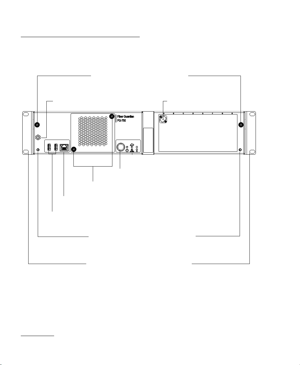
Banana plug connector for antistatic strap
USB host ports
Ethernet local access port
(to connect a portable computer to the unit)
Retaining screws/handles to slide the unit in
or out of its case (OTDR replacement)
Retaining screws/handles to access the fan and air filter
OTDR port
On/Off button
LEDs
Mounting brackets for installation in a rack
(not assembled on the unit at time of shipment)
Front
To install the optional fiber management tray
Introducing the FG-750 Fiber Guardian
Available Models
Fiber Guardian without Switch Ports
4 FG-750
Page 19
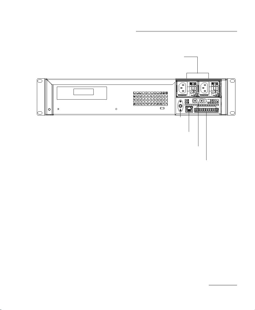
Introducing the FG-750 Fiber Guardian
Replaceable power supply modules
(AC model shown)
Port for 3G/4G antenna
Ethernet port
(for LAN/WAN connection)
Dry contact relays
Grounding lug
Back
Available Models
Fiber Guardian 5
Page 20
Introducing the FG-750 Fiber Guardian
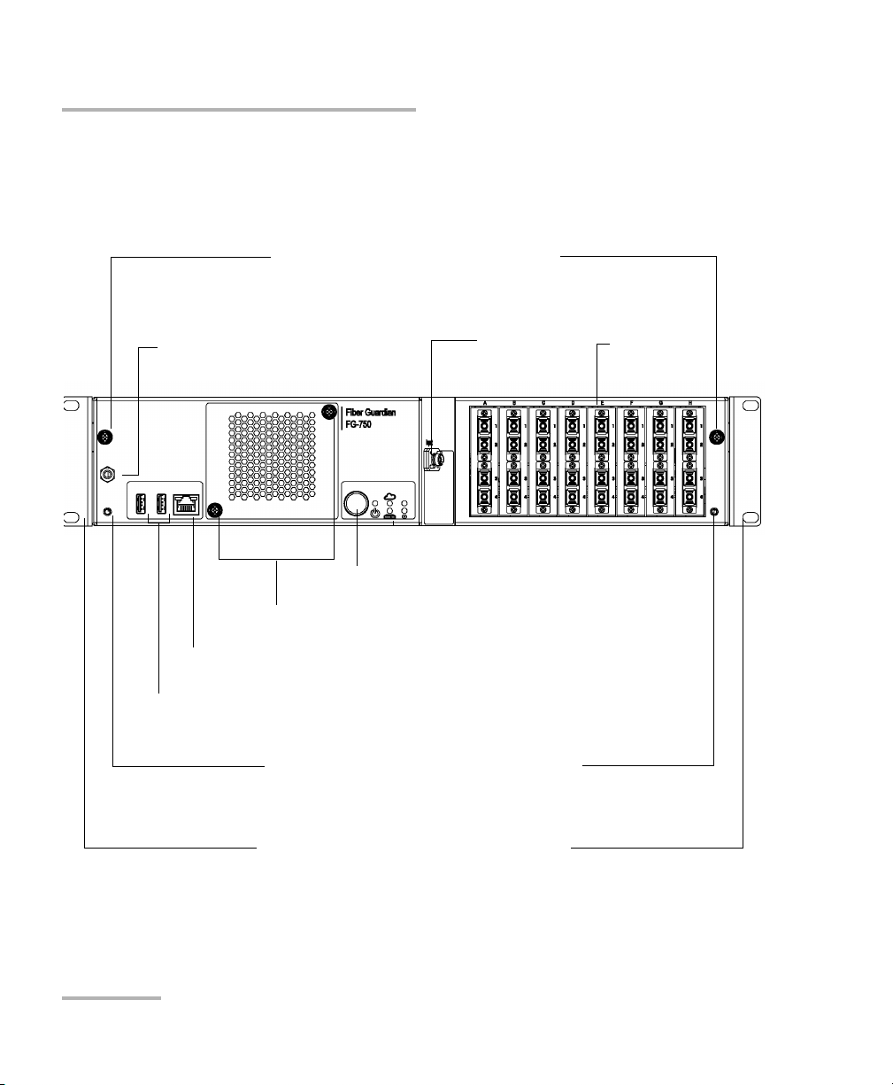
Banana plug connector for
antistatic strap
USB host ports
Ethernet local access port
(to connect a portable computer to the unit)
Retaining screws/handles to slide the unit in
or out of its case (OTDR replacement, except
for the remote OTAU units; switch cassettes
insertion and removal)
Retaining screws/handles to access the fan and air filter
Input port
(remote OTAU
only)
On/Off button
LEDs
Front
Switch
ports
Mounting brackets for installation in a rack
(not assembled on the unit at time of shipment)
To install the optional fiber management tray
Available Models
Fiber Guardian with Switch Ports and
Remote OTAU
6 FG-750
Page 21

Introducing the FG-750 Fiber Guardian
Replaceable power supply modules
(AC model shown)
Port for 3G/4G antenna
Ethernet port
(for LAN/WAN connection)
Dry contact relays
Grounding lug
Back
Available Models
Fiber Guardian 7
Page 22
Introducing the FG-750 Fiber Guardian
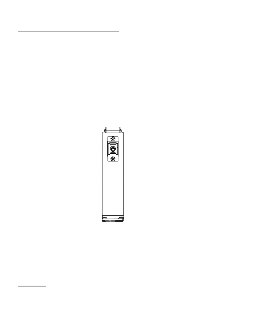
SC-Type Cassette (small jumper, no optical switch)
Available Optical Switch Cassette Configurations
Available Optical Switch Cassette
Configurations
When delivered with an optical switch, the minimum configuration for the
FG-750 is 1x4. The maximum is 1x96 with L1 (integrated first stage called
L1) being a 1x8 connected to MTP 12-port cassettes at the second stage.
Several possible configurations are available according to your needs.
Cassettes have various connector configurations to provide desirable port
density or preferred connection standards. When the cassettes do not fill
all the slots, you can use empty (short jumper) cassettes to avoid dust or
other elements that could interfere with your testing.
8 FG-750
Page 23
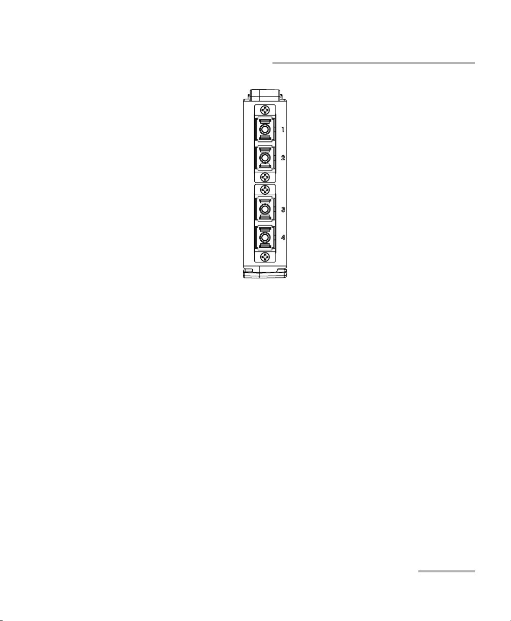
Introducing the FG-750 Fiber Guardian
SC-type cassette (4-port optical switch)
Available Optical Switch Cassette Configurations
Fiber Guardian 9
Page 24
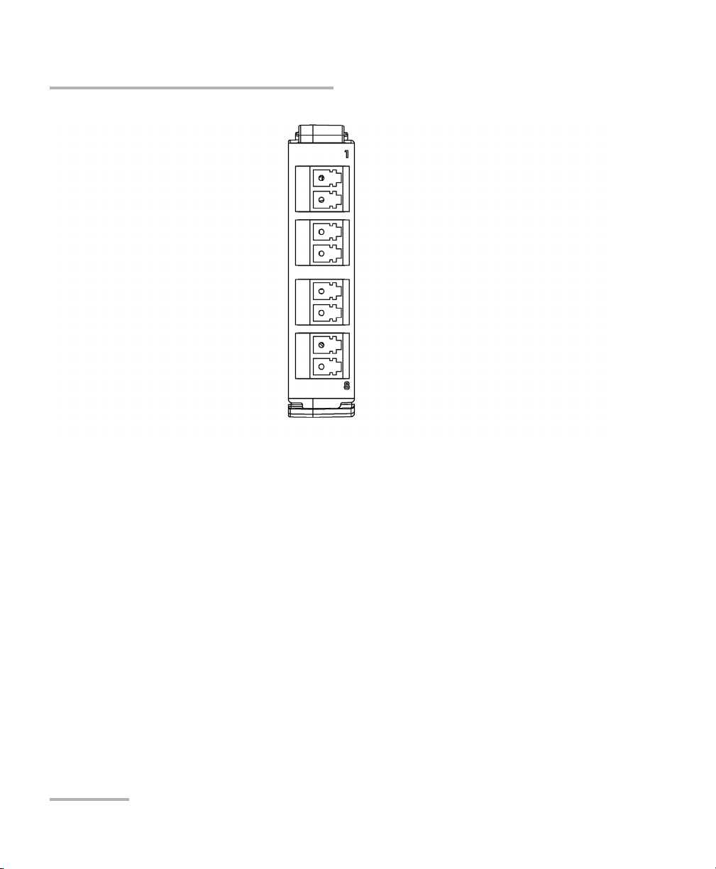
Introducing the FG-750 Fiber Guardian
LC-type cassette (8-port optical switch)
Available Optical Switch Cassette Configurations
10 FG-750
Page 25
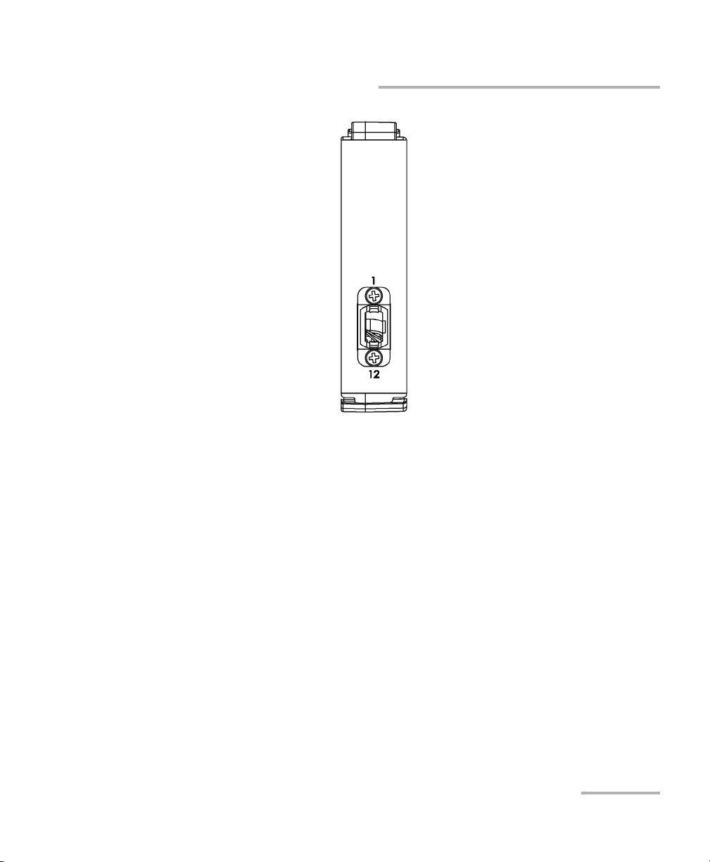
Introducing the FG-750 Fiber Guardian
MTP-type cassette (12-port MTP optical switch)
Available Optical Switch Cassette Configurations
Fiber Guardian 11
Page 26

Introducing the FG-750 Fiber Guardian
Pow er So urces
Power Sources
Your unit operates with the following power sources:
Replaceable power supply module (either AC or DC). Your unit needs
only one power supply module to work, but it can house two of them.
The second power supply provides redundancy. Your unit has been
certified with two power supplies of the same type (two AC or two DC).
The power supply modules are hot-swappable, which means that you
do not have to turn off your system to replace one of them. There is no
need to disassemble the unit to replace such a power supply. For more
information, see Replacing the Power Supply Modules on page 257.
Rechargeable battery (for clock). This battery can keep the date and
time for a very long time even if power is not connected to the unit.
Supported Web Browsers
The Host Web UI, the Line Configuration Web UI, the KVM remote console,
and NQMS Web App support the following Web browsers:
Internet Explorer 9 (IE9 mode only; compatibility mode not supported)
or later
Google Chrome, version 22.0 or later
Mozilla Firefox, version 16.0 or later
Note: If you want to work with the KVM remote console, you should ensure that
Java 6 or later is installed on the computer that you will use to connect to
this application.
Developing Your Own Test Applications
In Link-Aware™ mode, you can build your own network test and
management solution with the provided REST commands. For more
information, see Working with the REST Commands (Certain Models Only)
on page 79.
12 FG-750
Page 27

Introducing the FG-750 Fiber Guardian
Conventions
Before using the product described in this guide, you should understand
the following conventions:
WARNING
Indicates a potentially hazardous situation which, if not avoided,
could result in death or serious injury. Do not proceed unless you
understand and meet the required conditions.
CAUTION
Indicates a potentially hazardous situation which, if not avoided,
may result in minor or moderate injury. Do not proceed unless you
understand and meet the required conditions.
Conventions
CAUTION
Indicates a potentially hazardous situation which, if not avoided,
may result in component damage. Do not proceed unless you
understand and meet the required conditions.
IMPORTANT
Refers to information about this product you should not overlook.
Fiber Guardian 13
Page 28

Page 29

2 Safety Information
General Safety Information
WARNING
Do not install or terminate fibers while a light source is active.
Never look directly into a live fiber and ensure that your eyes are
protected at all times.
WARNING
The use of controls, adjustments and procedures, namely for
operation and maintenance, other than those specified herein may
result in hazardous radiation exposure or impair the protection
provided by this unit.
IMPORTANT
When you see the following symbol on your unit , make sure
that you refer to the instructions provided in your user
documentation. Ensure that you understand and meet the required
conditions before using your product.
IMPORTANT
Other safety instructions relevant for your product are located
throughout this documentation, depending on the action to
perform. Make sure to read them carefully when they apply to your
situation.
Fiber Guardian 15
Page 30

Safety Information
Laser Safety Information (Units with an OTDR)
Laser Safety Information (Units with an OTDR)
Your instrument is a Class 1M laser product in compliance with standards
IEC 60825-1: 2007 and 21 CFR 1040.10, except for deviations pursuant to
Laser Notice No. 50, dated June 24, 2007. Invisible laser radiation may be
encountered at the output port.
Viewing the laser output with certain optical instruments (for
example, eye loupes, magnifiers, and microscopes) within a
distance of 100 mm may pose an eye hazard.
The product is safe under reasonably foreseeable conditions of
operation but it may be hazardous if you use optics within a
diverging or collimated beam.
WARNING
IMPORTANT
16 FG-750
Page 31

Safety Information
Affix this label to the front panel of the unit.
Laser Safety Information (Units with an OTDR)
The following labels indicate that the product contains a laser source:
Your unit contains a replaceable OTDR module.
To avoid damaging your FG-750 Fiber Guardian, use only EXFO
OTDR modules of the OTM-7xx Series with it.
Fiber Guardian 17
CAUTION
Page 32

Safety Information
Laser Safety Information (Units without an OTDR)
Laser Safety Information (Units without an
OTDR)
The Fiber Guardian remote OTAU (switch) does not include laser
components in itself. However, it is used in conjunction with the FG-750
which contains an OTDR. See the content related to the models with OTDR
for further laser safety details and instructions.
18 FG-750
Page 33

Safety Information
Electrical Safety Information
Electrical Safety Information
WARNING
A readily accessible disconnect device must be installed on the
mains. The power cord of the AC unit can be considered the
disconnect device to the main power.
To avoid serious injuries as well as irreparable damages to your
unit, ALWAYS TURN OFF BOTH DISCONNECT DEVICES BEFORE
OPENING OR SERVICING THE UNIT.
Consideration should be given to the connection of the unit to
the supply circuit and the effect that overloading of the circuits
might have on over-current protection and supply wiring.
Appropriate consideration of equipment nameplate ratings
should be used when addressing this concern.
Ensure that your power supply is properly grounded and that
the power cable and power supply are compatible with the
unit.
The power supply in this product contains no user-serviceable
parts. There is more than one supply in this product. Refer
servicing only to qualified personnel.
Do not attempt to modify or use the supplied AC power cord if
it is not the exact type required. A product with more than one
power supply will have a separate AC power cord for each
supply.
Note: The AC power supply is not covered by the NEBS
certification.
Fiber Guardian 19
Page 34

Safety Information
Electrical Safety Information
Use this unit indoors only.
Position the unit so that air can circulate freely around it.
Operation of any electrical instrument around flammable gases
or fumes constitutes a major safety hazard.
To avoid electrical shock, do not operate the unit if any part of
the outer surface (covers, panels, etc.) is damaged.
Capacitors inside the unit may be charged even if the unit has
been disconnected from its electrical supply.
DO NOT connect the unit interfaces metallically to OSP (Outside
Plant) wiring. The unit interfaces are designed for use as intra
building surfaces only (Type 2 or Type 4 ports as described in
GR- 1089-CORE) and require isolation from the exposed OSP
cabling. The addition of Primary Protectors is not sufficient
protection in order to connect these interfaces metallically to
IOSP wiring.
WARNING
20 FG-750
Page 35

Safety Information
Electrical Safety Information
Equipment Ratings
Tem pe ra tu re
Operation
Storage
–5 °C to 50 °C (23 °F to 122 °F)
–40 °C to 70 °C (–40 °F to 158 °F)
Heat release 300 W/m2
Relative humidity 95 % non-condensing
Maximum operation
3000 m (9843 ft)
altitude
Pollution degree 2
Overvoltage category II
Input power
AC model
DC model
a. Not exceeding ± 10 % of the nominal voltage.
b. Range: –40 - –72 V
a
b
100 - 240 V; 50/60 Hz; 2 A/1 A
–48 V; 3 A
Fiber Guardian 21
Page 36

Page 37

3 Getting Started with Your
Fiber Guardian
The installation process can be divided into the following main steps:
Preparing for installation
Installing the unit in a rack
Connecting the devices
Turning on the unit
Connecting cables to the optical ports
WARNING
To avoid personal injuries and damages to the unit, you must
perform the procedures detailed in this section in the order they are
presented.
Preventing Electrostatic Discharge Damage
Electrostatic discharge (ESD) damage can cause complete or intermittent
equipment failures. Always use an ESD-preventive wrist or ankle strap and
ensure that it makes good skin contact. Connect the equipment end of the
connection cord into the ESD connector located on the front of your unit
(see Available Models on page 3).
All procedures for which the use of an antistatic strap is recommended will
be identified as such throughout this documentation.
Fiber Guardian 23
Page 38

Getting Started with Your Fiber Guardian
Preparing for Installation
Preparing for Installation
WARNING
The unit is designed to be installed in a limited access area, for
example, Central Offices, Telecommunication Centers, computer
rooms, wiring closet and similar type locations and in
accordance with local codes.
Only trained personnel can perform the unit installation and
configuration tasks. These people have appropriate technical
training and experience to be aware of the hazards to which a
person can be exposed when performing these installation
tasks.
IMPORTANT
Use only shielded cables for Ethernet connections to the unit. The
shielded cables must be grounded at both ends.
Before installing your unit, you should take the following into
consideration:
The chosen location provides adequate clearance for maintenance
procedures.
The location is an environmentally-controlled area that meets the
minimum operating parameters.
The location is isolated from strong electromagnetic fields produced by
electrical devices.
The power cable and power supply are compatible with your power
service.
The power source is properly grounded and falls within the internal
power supply rating.
The location is in an ESD-safe work area.
24 FG-750
Page 39

Getting Started with Your Fiber Guardian
Installing Your Unit in a Rack
Installing Your Unit in a Rack
The rack (which is not included with the unit) should provide sufficient
vertical clearance to insert the unit. The height of the unit is two rack
units (2U) high or about 3 1/2 inches.
All electrical cabling can be connected only through the back panel.
WARNING
The equipment rack must be anchored to an unmovable
support to prevent it from falling over when one or more
servers are extended in front of the rack on slides. You must also
consider the weight of any other device installed in the rack. A
crush hazard exists should the rack tilt forward which could
cause serious injury.
Mounting of the unit in a rack or cabinet should be such that a
hazardous condition is not achieved due to uneven mechanical
loading. The fully-configured unit is heavy. Use caution when
manipulating the unit. A lifting mechanism may be required for
installation.
There mounting brackets are available in three formats:
For 19-inch racks
For 21-inch (ETSI) racks
For 23-inch racks.
IMPORTANT
Ensure that you use the type of mounting brackets that
corresponds to the width of your rack.
The brackets have several rows of holes for more installation versatility. You
can install the unit with its front panel flush with the front of the rack, install
it forward, or even recessed in the rack.
Fiber Guardian 25
Page 40

Getting Started with Your Fiber Guardian
Bracket in standard position
Installing Your Unit in a Rack
To install the mounting brackets on your unit:
1. If necessary, turn off the unit and disconnect all optical fibers and
electrical cables.
2. Position the unit so that its bottom panel rests on a flat surface such as
a table.
3. Align the holes of the first bracket with the holes of the unit casing at
the position that best suits your installation needs. You can even invert
position of the mounting bracket if necessary.
26 FG-750
Page 41

Getting Started with Your Fiber Guardian
Bracket in inverted position
Installing Your Unit in a Rack
4. Fix the first bracket on the unit with the supplied screws (four screws
per bracket).
5. Repeat steps 3 and 4 with the other bracket, ensuring that you place
the bracket at the exact same position (orientation of the bracket, set
of holes on the bracket and on the unit’s casing).
6. Place the unit in the rack at the desired height.
7. Fix the unit in place using four 10-32 x 1/2 in. screws (four M6 screws
for the ETSI racks).
8. For NEBs installation, use thread-forming type unit mounting screws
that remove any paint or non-conductive coatings to establish a
metal-to-metal contact.
Fiber Guardian 27
Page 42

Getting Started with Your Fiber Guardian
Grounding Your Unit
Grounding Your Unit
To avoid the potential for an electrical shock hazard, you must reliably
connect an earth grounding conductor to the unit (AC and DC models).
Note: The DC units are intended for installation with an isolated DC return (DC-I)
and are to be installed in a Common Bonding Network (CBN) per NEBS
GR-1089.
IMPORTANT
Ensure to ground the unit using a grounding method that complies
with your local regulations.
If you are not sure on how to proceed, consult a certified
electrician.
To ground your unit:
1. Remove the two Phillips screws, and remove the grounding lug from
the rear panel of the unit.
2. Prepare the ground wire (minimum 14 AWG), and attach one of its
ends to the unit’s grounding lug using a crimping tool.
3. Use the two Phillips screws to attach the grounding lug and wire
assembly to the rear panel of the unit.
28 FG-750
Page 43

Getting Started with Your Fiber Guardian
Grounding Your Unit
4. Ground the other end of the wire as per your local regulation.
5. If a DC power supply is used, it needs to be grounded to the unit by
using 2 green wires.
Your unit is now grounded properly.
Fiber Guardian 29
Page 44

Getting Started with Your Fiber Guardian
Inserting or Removing Optical Switch Cassettes (Certain Models Only)
Inserting or Removing Optical Switch
Cassettes (Certain Models Only)
If your unit features optical switch cassettes, you can change the
configuration according to your test needs.
CAUTION
When removing a cassette, make sure to replace it with another
one so that the front opening of the unit is always filled. Leaving
empty spaces into the opening could allow dust and particles into
the unit, and compromise its optimal operation.
To insert a cassette into the unit:
1. If you are using a fiber management tray, remove the protective
window. For more information, see Working with the Fiber (Patchcord)
Management Tray on page 36.
2. Turn off the unit and disconnect it completely from the power sources
(turn off both disconnect devices).
3. Put on an antistatic strap and connect it to the connector provided for
that purpose on the front panel of the unit.
4. Loosen the retaining screws on each side of the unit.
5. Pull the unit out of its casing.
30 FG-750
Page 45

Getting Started with Your Fiber Guardian
Inserting or Removing Optical Switch Cassettes (Certain Models Only)
6. If you have not done so already, clean the optical fiber connector
located at the back of the cassette. For more information, see Cleaning
and Connecting Optical Fibers on page 77.
7. Insert the cassette through the top opening.
8. Connect the cassette to the unit using the optical connector at the back
of the cassette and the corresponding optical fiber.
Fiber Guardian 31
Page 46

Getting Started with Your Fiber Guardian
Inserting or Removing Optical Switch Cassettes (Certain Models Only)
9. Align the connector at the bottom of the cassette with the one inside
the unit, and push down. The cassette will snap into place.
10. Push the unit back into its casing and retighten the retaining screws.
11. If you are using a fiber management tray, put the protective window
back into place. For more information, see Working with the Fiber
(Patchcord) Management Tray on page 36.
To remove a cassette from the unit:
1. If you are using a fiber management tray, remove the protective
window. For more information, see Working with the Fiber (Patchcord)
Management Tray on page 36.
2. Turn off the unit and disconnect it completely from the power sources
(turn off both disconnect devices).
3. Put on an antistatic strap and connect it to the connector provided for
that purpose on the front panel of the unit.
4. If you have not done so already, disconnect any fiber from the front of
the cassette.
32 FG-750
Page 47

Getting Started with Your Fiber Guardian
Inserting or Removing Optical Switch Cassettes (Certain Models Only)
5. Loosen the retaining screws on each side of the unit.
6. Pull the unit out of its casing.
7. Disconnect the optical fiber from the cassette and put the fiber back on
the holder at the back of the unit.
8. Pull the module up using the tab located under the connector at the
back of the cassette.
Fiber Guardian 33
Page 48

Getting Started with Your Fiber Guardian
Inserting or Removing Optical Switch Cassettes (Certain Models Only)
9. Pull the module out.
10. Push the unit back into its casing and retighten the retaining screws.
11. If you are using a fiber management tray, put the protective window
back into place. For more information, see Working with the Fiber
(Patchcord) Management Tray on page 36.
34 FG-750
Page 49

Getting Started with Your Fiber Guardian
Installing FC Connectors
Installing FC Connectors
The 1x4 and 1x1 switch cassettes and FG750-ST model are equipped with
SC connectors by default. However, if you prefer, you can purchase FC
connectors as an accessory to replace the SC connectors.
CAUTION
To avoid damaging your unit, do not attempt to replace the
connectors on built-in switches.
To install FC connectors on switch cassettes:
1. Use a small Phillips screwdriver to remove the two screws on the SC
connector and expose the connector baseplate and ferrule.
2. Clean the new FC connector (see Cleaning Switchable Connectors on
page 240).
3. Fix the FC connector onto the connector baseplate with the two
screws.
When you have finished installing the connectors and have reconnected
the optical fibers, you can resume all optical route testing.
Fiber Guardian 35
Page 50

Getting Started with Your Fiber Guardian
Working with the Fiber (Patchcord) Management Tray
Working with the Fiber (Patchcord)
Management Tray
You can install an optional fiber management tray on your unit.
Note: The fiber tray is not covered by the NEBS certification.
The tray comprises a fixed part that you screw in place on your unit, and a
mobile part (protective window). The protective window can be either
folded down (access to the fan block or filter) or removed completely
(insertion or removal of switch cassettes). As for the fiber management
clips (into which you slide the fibers), there are five possible positions for
more installation versatility.
To install the fiber management tray:
1. Carefully align the screws of the fiber management tray with the holes
on the front of your unit.
36 FG-750
Page 51

Getting Started with Your Fiber Guardian
Working with the Fiber (Patchcord) Management Tray
2. Slide the tray toward the unit until it makes contact with the casing of
the unit.
Fiber Guardian 37
Page 52

Getting Started with Your Fiber Guardian
Turn screws clockwise
Working with the Fiber (Patchcord) Management Tray
3. Using a Phillips screwdriver, turn the retaining screws clockwise until
the tray is secured in place.
38 FG-750
Page 53

Getting Started with Your Fiber Guardian
Clip holes
(two on the left
and three on the
right)
Plastic fiber clip
Working with the Fiber (Patchcord) Management Tray
4. Position a plastic fiber clip as shown below, and snap it into the desired
clip hole, depending on the configuration that you want to use.
5. Repeat the previous step with all the fiber management clips that you
Fiber Guardian 39
want to install (maximum of five clips in all).
Page 54

Getting Started with Your Fiber Guardian
Pin located on the
protective window
Slot located on the
fixed part of the tray
Pin located on the
protective window
Slot located on the
fixed part of the tray
Working with the Fiber (Patchcord) Management Tray
6. Install the protective window as follows:
6a. Hold the protective window so that you see its flat side.
6b. Carefully align the pins of the protective window with the slots on
the fixed part of the tray.
6c. Slide the pins of the protective window all the way down into the
slots.
40 FG-750
Page 55

Getting Started with Your Fiber Guardian
Pin located on the fixed
part of the tray
Slot located on the side
of the protective window
Working with the Fiber (Patchcord) Management Tray
6d. Position the protective window vertically, and push it slightly so
that the slot on each side of the window rests on the
corresponding pin on the tray.
Your fiber management tray is now installed properly. You will simply need
to slide the fibers into the fiber management clips when you are ready to
use the tray.
Fiber Guardian 41
Page 56

Getting Started with Your Fiber Guardian
Pin located on the fixed
part of the tray
Slot located on the side
of the protective window
Working with the Fiber (Patchcord) Management Tray
To fold down the protective window:
1. Slightly pull the protective window upwards to release it from its
seated position.
2. Once the protective window can move freely, fold it all the way down
until it stops.
42 FG-750
Page 57

Getting Started with Your Fiber Guardian
Pin located on the fixed
part of the tray
Slot located on the side
of the protective window
Working with the Fiber (Patchcord) Management Tray
To remove the protective window:
1. Slightly pull the protective window upwards to release it from its
seated position.
Fiber Guardian 43
Page 58

Getting Started with Your Fiber Guardian
Pin located on the
protective window
Slot located on the
fixed part of the tray
Pin located on the
protective window
Slot located on the
fixed part of the tray
Working with the Fiber (Patchcord) Management Tray
2. Once the protective window can move freely, position the window so
that you can slide the pins of the protective window all the way out of
their slots.
44 FG-750
Page 59

Getting Started with Your Fiber Guardian
Connecting the Power and the Network Cables
Connecting the Power and the Network
Cables
Before starting to work with your unit, you must connect the power. You
may also wish to connect the LAN/WAN network cable, especially if you
intend to install your unit in a rack. You can also connect a network cable
for local access to the unit (front port).
The Fiber Guardian is available with either AC or DC power supplies. The
unit has redundant AC or redundant DC power modules. To benefit from
this redundancy, be sure to connect both power supplies, each to a
separate circuit.
WARNING
A certified over-current protecting device that is suitably rated
must be installed at the source.
All electrical installation and accessories must be done and
selected as per local electrical code and regulation.
As soon as you connect the unit to a power source, the Baseboard
Management Controller (BMC) starts its initialization. During this
operation, the LEDs on the front panel will be lit in the following
sequence:
All LEDs will turn to yellow for about 40 seconds.
All the LEDs will turn off for about 5 seconds.
Finally, the power LED ( ) will turn to blinking green, indicating
that the BMC is now ready (unit is in standby).
Note: Your unit has been designed to restart automatically when the power
comes back after a power outage. However, in this case, the initialization
sequence will differ from the usual initialization sequence explained above.
For detailed information about the LEDs, see LED Indicators Description on
page 286.
Fiber Guardian 45
Page 60

Getting Started with Your Fiber Guardian
Connecting the Power and the Network Cables
To connect the network cables:
1. To be able to operate the NQMS and REST commands via the
LAN/WAN, connect one end of a network cable to the Ethernet port
located at the back of your unit. Connect the other end of the cable to
the network itself.
2. If you need a local access to the unit, connect one end of a network
cable to the Ethernet port located at the front of your unit. Leave the
other end of the cable free for future connections with a portable
computer.
To connect the power to AC power supplies:
1. Connect the cords to the main power inlets located at the back of the
unit.
2. Connect the other end of the cords to the power sources.
As soon as the initialization sequence is complete (power LED is blinking
green), you are ready to turn on the unit (see Turning On or Off the Unit on
page 48).
46 FG-750
Page 61

Getting Started with Your Fiber Guardian
Connecting the Power and the Network Cables
To connect the power to DC power supplies:
1. Ensure all power is off or disconnected at the source.
Note: A certified over-current protection of 5 A must be installed at the power
secondary distribution.
2. Ensure that the unit is grounded properly. For more information,
see Grounding Your Unit on page 28.
3. Crimp each power lead (minimum 14 AWG) with a UL-listed pressure
terminal connector (ring type). The connector must be suitable for 14
AWG wires.
4. Pair the power leads with the appropriate power terminal (located at
the back of the unit), respecting the polarity as indicated just below the
terminal block.
5. Tighten the screws to attach the power leads to the unit.
6. Turn on the disconnect devices that are connected to the unit.
As soon as the initialization sequence is complete (power LED is blinking
green), you are ready to turn on the unit (see Turning On or Off the Unit on
page 48).
Fiber Guardian 47
Page 62

Getting Started with Your Fiber Guardian
Turning On or Off the Unit
Turning On or Off the Unit
As soon as you connect the unit to a power source, the companion starts
its initialization. Once the initialization is complete, you can turn on the
host. Once the host is on, the operating system will be started
automatically. Several components must be initialized before you can
actually send commands or connect to the unit.
For detailed information about the LEDs, see LED Indicators Description on
page 286.
Note: You can restart and turn off the host directly from the Host Web UI.
Note: Your unit has been designed to restart automatically when the power
comes back after a power outage.
48 FG-750
Page 63

Getting Started with Your Fiber Guardian
LEDs
Turning On or Off the Unit
To turn on the host:
Press the power button until the power LED turns to green (non-blinking)
and release it.
IMPORTANT
When the host is ready, the system LED turns to green
(non-blinking).
When network cables are connected to the unit (front and rear
ports), you must wait that the connection be established before the
system can be accessed.
Front port (Static-APIPA): about 60 seconds after the network
cable is connected.
Rear port (DHCP): a few seconds after the operating system is
loaded.
There is no visual or audible sign that the connection on the front
port is established.
To turn off the host “locally”:
When the unit is on, press the power button for one second and release it.
First, the system LED will turn to blinking green, and then turn off. Finally,
the power LED will turn back to blinking green (standby mode), indicating
that the host has been shut down properly.
Fiber Guardian 49
Page 64

Getting Started with Your Fiber Guardian
Connecting a Monitoring Device to the Dry Contact Relays
To restart the host from the Host Web UI:
1. Connect to the Host Web UI. For more information, see Accessing and
Exiting the Host Web UI on page 87.
2. From the main menu, select Actions > Restart Host.
3. When the application prompts you to confirm the action, click Yes.
To turn off the host from the Host Web UI:
1. Connect to the Host Web UI. For more information, see Accessing and
Exiting the Host Web UI on page 87.
2. From the main menu, select Actions > Turn Off Host.
3. When the application prompts you to confirm the action, click Yes.
Note: Once the unit has been shut down, you will have to turn it on manually (by
pressing the button on the front panel) to be able to use it.
Connecting a Monitoring Device to the Dry
Contact Relays
Your unit is equipped with dry contact relays that enable you to connect
your own monitoring device if you wish to do so.
There are three dry contact relays ( 65 V; 0.46 A) on the back panel of
the unit:
Power relay: Activated when all components related to the host are
powered on (the power LED is green and does not blink).
System relay: Activated when the software and hardware (power, fan
speed, temperature) are working normally.
User-defined relay: Used for NQMS Optical Route monitoring and is
activated when a fault is detected on an optical route.
50 FG-750
Page 65

Getting Started with Your Fiber Guardian
System relay
Pin 4 - NC = Normally Closed
Pin 5 - C = Common
Pin 6 - NO = Normally Open
User-defined relay
Pin 7 - NC = Normally Closed
Pin 8 - C = Common
Pin 9 - NO = Normally Open
Power relay
Pin 1 - NC = Normally Closed
Pin 2 - C = Common
Pin 3 - NO = Normally Open
Connecting a Monitoring Device to the Dry Contact Relays
To connect a monitoring device to the dry contact relays:
See the diagram below to determine where you should connect the wires.
Fiber Guardian 51
Page 66

Getting Started with Your Fiber Guardian
Connecting an External Switch
Connecting an External Switch
When you need extra switch ports, you can purchase an external switch
that you will connect to your FG-750 unit.
WARNING
To avoid serious injuries, always follow all the connection and
safety instructions provided with your external switch.
If you are working with a Fiber Guardian remote OTAU, see Safety
Information on page 15 and Getting Started with Your Fiber
Guardian on page 23.
CAUTION
To avoid damaging your unit, use only external switches approved
by EXFO with it.
If you are working with a Fiber Guardian remote OTAU, all the information
regarding this switch is available in this documentation. However, for other
models of external switches, if you need information on the connection
procedures, the location of the various ports, or the configuration of the IP
address, refer to the documentation that came with your switch.
52 FG-750
Page 67

Getting Started with Your Fiber Guardian
Network (RJ-45) cable - Ethernet
Network (RJ-45) cable - Ethernet
Fiber Guardian unit External switch
Connecting an External Switch
To connect an external switch to your unit:
1. Connect one network cable to the rear Ethernet port of your unit, and
one network cable to the LAN Ethernet port of the external switch.
Note: If you are not sure which port to use, refer to the documentation that came
with your external switch for the exact location of the LAN Ethernet port.
2. Connect both network cables to the same network (LAN).
Fiber Guardian 53
Page 68

Getting Started with Your Fiber Guardian
Jumper cable or
long feeder fiber
Fiber Guardian unit External switch
Connecting an External Switch
3. Connect one end of a jumper cable (or of a long feeder fiber) to the
OTDR port (units without switch ports), or to any switch port of your
choice on your Fiber Guardian unit.
4. Connect the other end of the jumper cable (or of the long feeder fiber)
to the input port of the external switch.
Note: Depending on the external switch that you have, the input port may be
labelled differently (master port, common port, etc.) or located at the back
of the unit. Refer to the user documentation that came with your external
switch for more information.
Note: Using a long feeder fiber will incur more attenuation, which will have to be
taken into account when calculating the maximum OTDR reach.
Note: It is possible to cascade external switches. You would simply need to
connect one port of an already connected switch to the input port of the
external switch to add.
54 FG-750
Page 69

Getting Started with Your Fiber Guardian
Retrieving the IP Address of the Rear Ethernet Port (Host)
Retrieving the IP Address of the Rear Ethernet
Port (Host)
Before starting to work with the Web user interfaces or the provided REST
commands, you need to retrieve the IP address of the Ethernet port located
on the back panel of the unit.
IMPORTANT
Keep the IP address of the rear Ethernet port to a safe location. You
will need it later for most of the operations on your unit.
You will need to:
Connect a portable computer to your unit via the Ethernet port located
on its front panel.
Enter the IP address of the front Ethernet port of the unit and provide it
in the connection settings on the computer.
The (static) IP address is 169.254.10.10.
Enter the appropriate user name when the Host Web UI prompts you.
The user name that you should enter is Admin.
The password is Admin.
The procedure below will guide you through the necessary steps.
Fiber Guardian 55
Page 70

Getting Started with Your Fiber Guardian
Retrieving the IP Address of the Rear Ethernet Port (Host)
To retrieve the IP address of the rear Ethernet port:
1. If necessary, turn on your unit. If the unit was not powered on yet,
see Turning On or Off the Unit on page 48 for more information on the
startup sequence and waiting time.
Note: It may take a few minutes before your unit and the computer could “see”
each other.
2. Connect your portable computer to the front Ethernet port of the unit.
If you have already connected a network cable to your unit, simply
connect the free end of the cable to your computer.
Otherwise, connect a network cable between the unit (front port)
and your computer. You will have to wait about 60 seconds that the
detection of the port is complete once the operating system is
started.
3. Tu rn o n yo u r co mput er.
56 FG-750
Page 71

Getting Started with Your Fiber Guardian
Retrieving the IP Address of the Rear Ethernet Port (Host)
4. Connect to the Host Web UI as follows:
4a. From your computer, open a Web browser.
4b. In the address bar, type http://169.254.10.10/HostWebUI.
4c. When the application prompts you, enter Admin as the user name
and Admin as the password.
4d. Click OK to open the session.
5. In the Host Web UI, from the main menu, select Status > System
Information.
6. From the tree view, select Host Information.
Fiber Guardian 57
Page 72

Getting Started with Your Fiber Guardian
Retrieving the IP Address of the Rear Ethernet Port (Host)
7. Go to the Rear Adapter column and write down the IP address of the
rear port.
8. Once it is done, click the Logout button to log off from the Web UI.
9. Close the Web browser.
10. Disconnect the network cable from your computer.
You now know the IP address of the host rear port.
58 FG-750
Page 73

Getting Started with Your Fiber Guardian
Preparing Your Unit for 3G/4G Access
Preparing Your Unit for 3G/4G Access
If your unit is equipped with the optional 3G/4G feature, it can switch to the
wireless network automatically when the wired network is down.This
optional package consists of an internal wireless communication module
and an external antenna.
By default, your unit is configured to connect automatically to the wireless
network, but you can deactivate this feature if you prefer. You can also
specify a maximum number of minutes during which the unit can remain
connected to the wireless network.
When you receive your unit, it contains no Subscriber Identity Module
(SIM) card and the antenna is not connected. This means that you will
need to:
Purchase a compatible and unlocked SIM card from a provider offering
3G/4G services. If you need more information on the 3G/4G coverage
in your area, contact your regional EXFO sales representative.
Have the card activated (you must subscribe to a package of mobile
services).
Connect the antenna to your unit.
Insert the SIM card in your unit.
Configure the 3G/4G parameters via the Web UI.
Note: The 3G card is not covered by the NEBS certification.
Fiber Guardian 59
Page 74

Getting Started with Your Fiber Guardian
Preparing Your Unit for 3G/4G Access
To connect the antenna to your unit:
1. Carefully align the connector of the antenna with the 3G/4G port on
your unit and push the antenna gently towards the unit until it stops.
2. Gently screw the antenna’s connector to the 3G/4G port.
3. Position the antenna as needed for a maximum reception of the signal.
The antenna is ready to use.
Note: If the 3G/4G signal is not strong enough where your unit is installed, you
may have to use a 3G/4G antenna with cable (can be purchased from
EXFO as an accessory) instead of the provided antenna.
WARNING
To avoid serious injuries as well as irreparable damages to your unit,
ALWAYS TURN OFF BOTH DISCONNECT DEVICES BEFORE OPENING
OR SERVICING THE UNIT.
CAUTION
To avoid damaging your unit or its components, you should wear
an antistatic band during this maintenance operation. For more
information, see Preventing Electrostatic Discharge Damage on
page 23.
CAUTION
If you are using a 3G/4G antenna with cable, depending on your
setup, you may have to install a lightning protection system
between your Fiber Guardian unit and the cable’s antenna. Failure
to provide adequate lightning protection may lead to irreparable
damage to your unit.
60 FG-750
Page 75

Getting Started with Your Fiber Guardian
Fan compartment
Turn screws
counterclockwise
Preparing Your Unit for 3G/4G Access
To insert the SIM card in your unit:
1. Turn off the unit and disconnect it completely from the power sources
(turn off both disconnect devices).
2. Put on an antistatic strap and connect it to the connector provided for
that purpose on the front panel of the unit.
3. Turn the fan compartment screws counterclockwise until the
compartment is loose. Since the screws are captive screws, you
cannot remove them completely.
CAUTION
To avoid dropping the fan compartment and damaging the unit,
the fan, or the fan cord, hold the fan compartment firmly. Do not
allow the fan compartment to hang over the edge of a rack or a
table.
Fiber Guardian 61
Page 76

Getting Started with Your Fiber Guardian
Preparing Your Unit for 3G/4G Access
4. Using the screws as handles, gently pull away the fan compartment.
CAUTION
To prevent damage to your SIM card, avoid touching its gold area.
5. Hold the SIM card so that the gold area is facing down and that the
beveled corner is on the right.
62 FG-750
Page 77

Getting Started with Your Fiber Guardian
Beveled corner
Preparing Your Unit for 3G/4G Access
6. Slide the SIM card into the unit’s SIM card slot, and push it all the way to
the back of the card slot.
7. Put the fan compartment back in its bay (it should be flush with the
unit’s front panel).
8. Turn the fan compartment screws clockwise until the compartment is
secured into place.
9. Remove your antistatic strap.
10. Reconnect the unit to its power sources (turn on both disconnect
devices) and turn on your unit.
Note: Restarting your unit ensures that the SIM card is properly detected. You will
then be ready to configure the 3G/4G parameters.
Fiber Guardian 63
Page 78

Getting Started with Your Fiber Guardian
Preparing to Access Your Unit via a WAN or the Internet
To configure the 3G/4G parameters:
Log on to the Web UI and configure the 3G/4G parameters. For more
information on the configuration of these parameters, see Configuring the
3G/4G Settings on page 94.
Your unit is now ready to switch to the wireless network whenever the
wired network is down.
Preparing to Access Your Unit via a WAN or the
Internet
When your computer and your unit are connected to a same WAN or to the
Internet, you can access your unit remotely with your computer. The
connection is made possible by the use of a Virtual Private Network (VPN).
If you have purchased the 3G/4G option, the unit will also use a VPN to
connect to the wireless network when the wired network is down.
IMPORTANT
EXFO does not provide licenses for any VPN client or server
applications. You can use any VPN application supporting data
transfer over a 3G/4G wireless network.
The information hereafter is for guidance purposes only. The
installation and use may differ for VPN applications other than
LogMeIn Hamachi. If you are not sure how to proceed, contact your
network administrator.
Contact Hamachi to ensure that you can use a free version of the
LogMeIn Hamachi application or to purchase a license.
Before being able to work with a VPN, you must:
Install the LogMeIn Hamachi VPN client application on your computer.
Create your own VPN on the Hamachi server.
Install the LogMeIn Hamachi client on your unit.
64 FG-750
Page 79

Getting Started with Your Fiber Guardian
Preparing to Access Your Unit via a WAN or the Internet
The VPN that you will create will serve as a “connection” point between
your computer and your unit. You will need to use the Hamachi VPN client
application to connect to this new VPN.
Your unit must have access to the Internet to be able to configure it on the
Hamachi server.
IMPORTANT
You cannot install the VPN client on the unit via a WAN or the
Internet. You must either connect a portable computer (DHCP
adapter) to the front port of the unit, or connect both the unit and
a computer to a same LAN.
To install the LogMeIn Hamachi VPN client on your computer:
1. On your computer, open a Web browser and go to
https://secure.logmein.com/products/hamachi/download.aspx.
2. Download (save) the LogMeIn Hamachi VPN client application
(installation file) to your computer.
3. Double-click the installation file that you have just downloaded to start
the installation.
4. From the first window, select the desired language and click Next.
Follow the on-screen instructions.
Fiber Guardian 65
Page 80

Getting Started with Your Fiber Guardian
Preparing to Access Your Unit via a WAN or the Internet
5. When the installation is complete, from the LogMeIn Hamachi
window, click the Power on button to establish a connection with the
Hamachi server.
6. Under Client name, enter a name that will enable you to easily identify
your computer later.
66 FG-750
Page 81

Getting Started with Your Fiber Guardian
Preparing to Access Your Unit via a WAN or the Internet
7. Click Create to confirm the name and send a request for an address on
the Hamachi server.
8. Since no VPN has been created yet, create one as follows:
8a. Click Create a new network.
8b. Enter a network ID and a password for your VPN.
Fiber Guardian 67
Page 82

Getting Started with Your Fiber Guardian
Number of connections made at
least one time to this VPN /
Maximum number of
connections allowed in total
ID of the VPN (acts as the
address to the server)
Computer name
Hamachi Address
Preparing to Access Your Unit via a WAN or the Internet
8c. Click Create to complete the process.
8d. Once the VPN is created, click the Power off button and close the
window.
Note: Even though the VPN has been created from your computer, it is hosted on
the Hamachi server, not on your computer directly.
68 FG-750
Page 83

Getting Started with Your Fiber Guardian
Preparing to Access Your Unit via a WAN or the Internet
To install the LogMeIn Hamachi VPN client on your unit:
1. Transfer the installation file to your unit either as explained below, or by
using an FTP client (such as FileZilla FTP client) from your computer.
Note: Once the transfer is complete, you can go to step 2.
1a. Connect a USB key to your computer and copy the LogMeIn
Hamachi installation file to your key.
1b. From your computer, connect to your unit using the KVM remote
console. For more information, see Connecting to Your Unit Using
the KMV Remote Console on page 295.
1c. In the Remote Console, from the main menu, select Media >
Virtual Media Wizard.
Fiber Guardian 69
Page 84

Getting Started with Your Fiber Guardian
Drive letter
associated to
your USB key
Preparing to Access Your Unit via a WAN or the Internet
1d. Under Hard disk/USB Key Media 1, select your USB key from the
list. The drive letter associated with your USB key in this
application should be exactly the same as you could see under
Windows if you would open a file explorer on your computer.
1e. Click Connect Hard disk/USB Key.
1f. Click Close.
70 FG-750
Page 85

Getting Started with Your Fiber Guardian
Preparing to Access Your Unit via a WAN or the Internet
1g. In the Remote Console, from Computer, double-click the USB key
to view its content.
1h. Copy the LogMeIn Hamachi installation file and paste it to the
desktop (or the folder of your choice) of your unit.
2. Double-click the installation file that you have just copied to start the
installation.
3. From the first window, select the desired language and click Next.
Follow the on-screen instructions.
Fiber Guardian 71
Page 86

Getting Started with Your Fiber Guardian
Preparing to Access Your Unit via a WAN or the Internet
4. When the installation is complete, from the LogMeIn Hamachi
window, click the Power on button to establish a connection with the
Hamachi server.
5. Under Client name, enter a name that will enable you to easily identify
your unit later.
6. Click Create to confirm the name and send a request for an address on
the Hamachi server.
72 FG-750
Page 87

Getting Started with Your Fiber Guardian
Preparing to Access Your Unit via a WAN or the Internet
7. Once the connection is established, from the LogMeIn Hamachi
window, connect to the VPN that you have created earlier.
7a. Click the Join an existing network button.
7b. Enter the ID of your VPN and the corresponding password.
7c. Confirm with Join.
IMPORTANT
Do not leave the VPN (network) and do not log off from the
Hamachi server from your unit.
Do not close the LogMeIn Hamachi window with the Power off
button. Otherwise, you will not be able to access your unit from a
WAN or the Internet later.
7d. Close the window with the button (not the Power off button).
You are now able to access your unit from your computer via a WAN or the
Internet.
Fiber Guardian 73
Page 88

Getting Started with Your Fiber Guardian
Connecting to the VPN
Connecting to the VPN
When your computer and unit are both connected to a WAN or the
Internet, you need to join the VPN from your computer and to retrieve the
LogMeIn address of your unit before being able to connect to the Host Web
UI or the Line Configuration Web UI.
The VPN client must be installed on both your computer and your unit
already. For more information on how to install the VPN client,
see Preparing to Access Your Unit via a WAN or the Internet on page 64.
To connect to the VPN:
1. From your computer, start the LogMeIn Hamachi client application.
2. Click the Power on button to establish a connection with the Hamachi
server.
74 FG-750
Page 89

Getting Started with Your Fiber Guardian
Connecting to the VPN
3. Click the Join an existing network button.
4. Enter the ID of your VPN and the corresponding password
.
5. Confirm with Join.
Fiber Guardian 75
Page 90

Getting Started with Your Fiber Guardian
Connecting to the VPN
6. Write down the Hamachi address (which begins with 5.x) that has
been assigned to the unit.
You are now ready to connect to the desired application.
76 FG-750
Page 91

Getting Started with Your Fiber Guardian
Cleaning and Connecting Optical Fibers
Cleaning and Connecting Optical Fibers
IMPORTANT
To ensure maximum power and to avoid erroneous readings:
Always inspect fiber ends and make sure that they are clean as
explained below before inserting them into the port. EXFO is
not responsible for damage or errors caused by bad fiber
cleaning or handling.
Ensure that your patchcord has appropriate connectors. Joining
mismatched connectors will damage the ferrules.
To connect the fiber-optic cable to the port:
1. Inspect the fiber using a fiber inspection microscope. If the fiber is
clean, proceed to connecting it to the port. If the fiber is dirty, clean it as
explained below.
2. Clean the fiber ends as follows:
2a. Gently wipe the fiber end with a lint-free swab dipped in isopropyl
alcohol.
2b. Use compressed air to dry completely.
2c. Visually inspect the fiber end to ensure its cleanliness.
Fiber Guardian 77
Page 92

Getting Started with Your Fiber Guardian
Cleaning and Connecting Optical Fibers
3. Carefully align the connector and port to prevent the fiber end from
touching the outside of the port or rubbing against other surfaces.
If your connector features a key, ensure that it is fully fitted into the
port’s corresponding notch.
4. Push the connector in so that the fiber-optic cable is firmly in place,
thus ensuring adequate contact.
If your connector features a screwsleeve, tighten the connector
enough to firmly maintain the fiber in place. Do not overtighten, as this
will damage the fiber and the port.
Note: If your fiber-optic cable is not properly aligned and/or connected, you will
notice heavy loss and reflection.
EXFO uses good quality connectors in compliance with EIA-455-21A
standards.
To keep connectors clean and in good condition, EXFO strongly
recommends inspecting them with a fiber inspection probe before
connecting them. Failure to do so will result in permanent damage to the
connectors and degradation in measurements.
78 FG-750
Page 93

Getting Started with Your Fiber Guardian
Working with the REST Commands (Certain Models Only)
Working with the REST Commands (Certain
Models Only)
You can build your own test applications with the provided REST
commands. You can refer to the Using iOLM Measurement Services and
Using FG-700 Series REST Services documentation for detailed information.
IMPORTANT
The computer that you intend to use to send commands must
be connected to the same network as the unit.
You must know the IP address of the rear Ethernet port. If you
do not know the IP address of the port, see Retrieving the IP
Address of the Rear Ethernet Port (Host) on page 55.
It is possible to test the link to the rear Ethernet port by trying to access the
REST documentation on the unit.
To access the REST documentation:
1. Connect to the Host Web UI. For more information, see Accessing and
Exiting the Host Web UI on page 87.
2. From the main menu, select Actions > Applications.
3. Click the link corresponding to the document that you want to view.
Fiber Guardian 79
Page 94

Getting Started with Your Fiber Guardian
Installing the Notification Agent on Your Computer
Installing the Notification Agent on Your
Computer
The Notification Agent is an application that you can install on any
computer that can “view” the RTUs, which usually means that the
computer and RTUs are connected to the same network. It monitors one or
several RTUs and warns you whenever faults are detected.
To install the Notification Agent on your computer:
1. Verify if you need to install the .NET Framework 4.0 or higher on your
computer as follows:
1a. From your computer, go to the Control Panel.
1b. Start Add/Remove Programs.
1c. From the list of programs that are already installed on your
computer, try to locate Microsoft .NET Framework 4.0 or higher.
If this item is on the list, you do not need to install .NET
Framework 4.0 or higher; otherwise, you will need to install it.
2. Start the RTU application (see Setting Up Your RTU on page 111).
3. Install the Notification Agent as follows:
3a. From the main menu of the NqmsWebOtdr2 application, select
About > Tool s.
3b. Under EXFO Software, click the hyperlink to retrieve the
necessary file.
80 FG-750
Page 95

Getting Started with Your Fiber Guardian
Installing the Notification Agent on Your Computer
3c. Save the file to a location of your choice on your computer.
3d. Double-click the .msi file to start the installation and follow the
instructions on the screen.
You are now ready to use the Notification Agent. For more information,
see Configuring the Notification Agent on page 142.
Fiber Guardian 81
Page 96

Getting Started with Your Fiber Guardian
Understanding the Applications, User Accounts and Passwords
Understanding the Applications, User
Accounts and Passwords
There are several ways to interact with your Fiber Guardian unit.
The table below summarizes the information about the different
applications as well as the corresponding user names and passwords.
Application Connection
HostWebUI:
To configure the
host and
companion
settings
To m onit o r the
system (event log)
Computer connected directly to the
unit (front port):
From your computer, in a Web
browser, type:
http://Front_Port_IP_
Address/HostWebUI
LAN connection:
From your computer, in a Web
browser, type:
http://Rear_Port_IP_
Address/HostWebUI
WAN or Internet connection:
From your computer (already
connected to the VPN), in a Web
browser, type: http://LogMeIn_
Hamachi_ Address/HostWebUI
User Name and
Default Password
User name: Admin
Password: Admin
82 FG-750
Page 97

Getting Started with Your Fiber Guardian
Understanding the Applications, User Accounts and Passwords
Application Connection
Fiber Guardian (OTDR
mode)
Computer connected directly to the
unit (front port):
From your computer, in a Web
browser, type:
http://Front_Port_IP_ Address
LAN connection:
From your computer, in a Web
browser, type:
http://Rear_Port_IP_ Address
WAN or Internet connection:
From your computer (already
connected to the VPN), in a Web
browser, type: http://LogMeIn_
Hamachi_ Address
User Name and
Default Password
User name: Admin
Pass w o r d : A dm i n
Fiber Guardian 83
Page 98

Getting Started with Your Fiber Guardian
Understanding the Applications, User Accounts and Passwords
Application Connection
Optical lines test Web
UI: To link your lines
and switch ports
according to your
tests.
In the Host Web UI, from the main
menu, select Actions > Applications.
Click the link corresponding to the Line
Configuration Web UI.
OR
Computer connected directly to the
unit (front port):
From your computer, in a Web
browser, type:
http://Front_Port_IP_
Address/LineConfiguration
LAN connection:
From your computer, in a Web
browser, type:
http://Rear_Port_IP_ Address/
LineConfiguration
WAN or Internet connection:
From your computer (already
connected to the VPN), in a Web
browser, type: http://LogMeIn_
Hamachi_ Address/
LineConfiguration
User Name and
Default Password
User name: Admin
Password: Admin
List of the REST
commands
In the Host Web UI, from the main
menu, select Actions > Applications.
User name: Admin
Password: Admin
Click the link corresponding to the list
that you want to view.
REST documentation In the Host Web UI, from the main
menu, select About > Help.
User name: Admin
Password: Admin
Click the link corresponding to the
document that you want to view.
84 FG-750
Page 99

Getting Started with Your Fiber Guardian
Understanding the Applications, User Accounts and Passwords
Application Connection
Your own application
using the REST
commands
Your favorite FTP
client application: To
transfer software
packages to your unit
if you do not wish to
use the provided
upload feature.
The user name and password must be
sent with each command as a “basic
authentication” header.
Via an FTP client application from your
computer.
Computer connected directly to the
unit (front port):
The FTP server address will
correspond to the
Front_Port_IP_ Address
LAN connection:
The FTP server address will
correspond to the
Rear_Port_IP_ Address
WAN or Internet connection:
The FTP server address will
correspond to the
LogMeIn_ Hamachi_ Address
User Name and
Default Password
User name:
WebServicesUser
Pas sword:
WebServicesUser
User name: Admin
Pass w o r d : A dm i n
Direct connection to
the unit (in Windows)
for troubleshooting
and installation of VPN
client application.
Fiber Guardian 85
Via the KVM application
(see Connecting to Your Unit Using the
KMV Remote Console on page 295).
User name:
Administrator
Pas sword:
RTUEXFO123
Page 100

Getting Started with Your Fiber Guardian
Understanding the Applications, User Accounts and Passwords
Note: If you do not know the IP address of the rear Ethernet port, see Retrieving
the IP Address of the Rear Ethernet Port (Host) on page 55.
Note: If you do not know the LogMeIn Hamachi address of your unit, or how to
connect to the VPN, see Preparing to Access Your Unit via a WAN or the
Internet on page 64 and Connecting to the VPN on page 74. If you are using
a VPN client application other than LogMeIn Hamachi, see with your
network administrator for the specific connection procedure.
86 FG-750
 Loading...