

Page 1
ETS-1000L
Ethernet Tester Analyzer
User Guide
Page 2

Copyright © 2010–2014 EXFO Inc. All rights reserved. No part of this
publication may be reproduced, stored in a retrieval system or transmitted
in any form, be it electronically, mechanically, or by any other means such
as photocopying, recording or otherwise, without the prior written
permission of EXFO Inc. (EXFO).
Information provided by EXFO is believed to be accurate and reliable.
However, no responsibility is assumed by EXFO for its use nor for any
infringements of patents or other rights of third parties that may result from
its use. No license is granted by implication or otherwise under any patent
rights of EXFO.
EXFO’s Commerce And Government Entities (CAGE) code under the North
Atlantic Treaty Organization (NATO) is 0L8C3.
The information contained in this publication is subject to change without
notice.
Trademarks
EXFO’s trademarks have been identified as such. However, the presence
or absence of such identification does not affect the legal status of any
trademark.
Units of Measurement
Units of measurement in this publication conform to SI standards and
practices.
April 10, 2014
Version number: 2.0.0
ii ETS-1000L
Page 3

Certification Information
Certification Information
Federal Communications Commission (FCC) and
Industry Canada (IC) Information
Electronic test and measurement equipment is exempt from FCC Part 15
compliance in the United States and from IC ICES 003 compliance in
Canada. However, EXFO Electro-Optical Engineering Inc. (EXFO) makes
reasonable efforts to ensure compliance to the applicable standards.
The limits set by these standards are designed to provide reasonable
protection against harmful interference when the equipment is operated in
a commercial environment. This equipment generates, uses, and can
radiate radio frequency energy and, if not installed and used in accordance
with the user guide, may cause harmful interference to radio
communications. Operation of this equipment in a residential area is likely
to cause harmful interference in which case the user will be required to
correct the interference at his own expense.
European Union (CE) Information
Electronic test and measurement equipment is subject to the EMC
Directive in the European Union. The EN61326 standard prescribes both
emission and immunity requirements for laboratory, measurement, and
control equipment. This unit has been tested and found to comply with the
limits for a Class A digital device. Please refer to the CE Declaration of
Conformity on page iv.
Note: If the equipment described herein bears the CE symbol, the said equipment
complies with the applicable European Union Directive and Standards
mentioned in the Declaration of Conformity.
Ethernet Tester Analyzer iii
Page 4
Certification Information
Application of Council Directives: 2006/95/EC - The Low Voltage Directive
2004/108/EC - The EMC Directive
2006/66/EC - The Battery Directive
93/68/EEC - CE Marking
And their amendments
Manufacturer’s Name: EXFO Inc.
Manufacturer’s Address: 400 Godin Avenue
Quebec, Quebec
Canada, G1M 2K2
Equipment Type: Information Technology Equipment (ITE)
Trade Name/Model No.: Ethernet Loopback Device / ETS-1000L
Standard(s) to which Conformity is Declared:
EN 55022: 2006 Information technology equipment Radio disturbance
characteristics Limits and methods of measurement
EN 55024 :1998 + A1: 2001 +
A2: 2003
Information Technology Equipment - Immunity
Characteristics - Limits and Methods of Measurements
EN 61010-1:2001 Edition 2.0 Safety Requirements for Electrical Equipment for Measurement,
Control, and Laboratory Use Part 1: General Requirements.
EN 60825-1:2007 Edition 2.0 Safety of laser products Part 1: Equipment classification and
requirements
EN 61000-3-2:2006 Electromagnetic compatibility (EMC).
Limits for harmonic current emissions (equipment input current
< 16 A per phase)
EN 61000-3-3:1995 + A1: 2001
+ A2: 2005
Electromagnetic compatibility (EMC).
Limits. Limitation of voltage changes, voltage fluctuations and
flicker in public low-voltage supply systems, for equipment with
rated current 16 A per phase and not subject to conditional
connection
I, the undersigned, hereby declare that the equipment specified above conforms to the above Directives and Standards.
Manufacturer
Signature:
Full Name: Stephen Bull, E. Eng
Position: Vice-President Research and
Development
Address: 400 Godin Avenue, Quebec (Quebec),
Canada, G1M 2K2
Date: February 08, 2010
DECLARATION OF CONFORMIT
Y
CE Declaration of Conformity
iv ETS-1000L
Page 5

Contents
Contents
Certification Information ....................................................................................................... iii
1 Introducing the ETS-1000L ........................................................................... 1
Overview .................................................................................................................................1
External Connectors ................................................................................................................4
Conventions ............................................................................................................................5
2 Safety Information ....................................................................................... 7
Laser Safety Warnings .............................................................................................................7
Installation Instructions Warnings ..........................................................................................8
3 Getting Started ............................................................................................ 9
4 Loopback .................................................................................................... 11
Loopback Adjustment ...........................................................................................................13
5 Remote Management ................................................................................ 15
OAM .....................................................................................................................................18
Upgrading Versions of the Software .....................................................................................19
6 Maintenance ............................................................................................... 21
Recycling and Disposal (Applies to European Union Only) ....................................................22
7 Troubleshooting ......................................................................................... 23
Solving Common Problems ...................................................................................................23
Contacting the Technical Support Group ..............................................................................24
Transportation ......................................................................................................................25
8 Warranty ..................................................................................................... 27
General Information .............................................................................................................27
Liability .................................................................................................................................28
Exclusions .............................................................................................................................29
Certification ..........................................................................................................................29
Service and Repairs ...............................................................................................................30
EXFO Service Centers Worldwide ..........................................................................................31
A Specifications ............................................................................................. 33
B Bibliography ............................................................................................... 35
Index ................................................................................................................ 37
Ethernet Tester Analyzer v
Page 6

Page 7
1 Introducing the ETS-1000L
Ethernet/Gigabit Ethernet loopback unit ETS-1000L (referred to as unit,
analyzer) is intended for performing loopback at the physical, data link,
network and transport layers of the OSI model.
The unit allows to carry out loopback control via OAM protocol and remote
control via TELNET protocol.
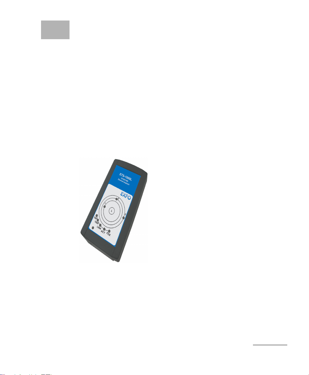
Overview
This section describes all connectors (ports) and LEDs available on the
ETS-1000L.
Front Panel
Ethernet Tester Analyzer 1
Page 8
Introducing the ETS-1000L
Overview
LEDs
The green color of LEDs corresponds to a loopback layer.
1 — physical layer (1)
2 — data link layer (2)
3 — network layer (3)
1+3 — transport layer (4)
Loopback Control (L)
This button is available for loopback mode control. To switch between
layers 1, 2, 3, 4 or turn loopback off, press this button till required selection
is made.
Link Speed LED Indicators
LED indicators represents link speed.
Speed LED LED Colors
10 Mbit/s 100 and 1000 green
100 Mbit/s 100 green
1000 Mbit/s 1000 green
Link
LED indicators represents link state.
Link State LED Colors
Connection is established green
No connection established off
2 ETS-1000L
Page 9
ACT
LED shows the data transmission state:
Data Transmission State LED Colors
Introducing the ETS-1000L
Overview
Data is being transmitted or received
currently
No data is being transmitted or
received currently
green
off
FDX
LED shows Ethernet interface state:
Ethernet Interface State LED Colors
Full-duplex connection green
Half-duplex connection off
Power
LED lights up when the power supply unit is connected.
Ethernet Tester Analyzer 3
Page 10
Introducing the ETS-1000L
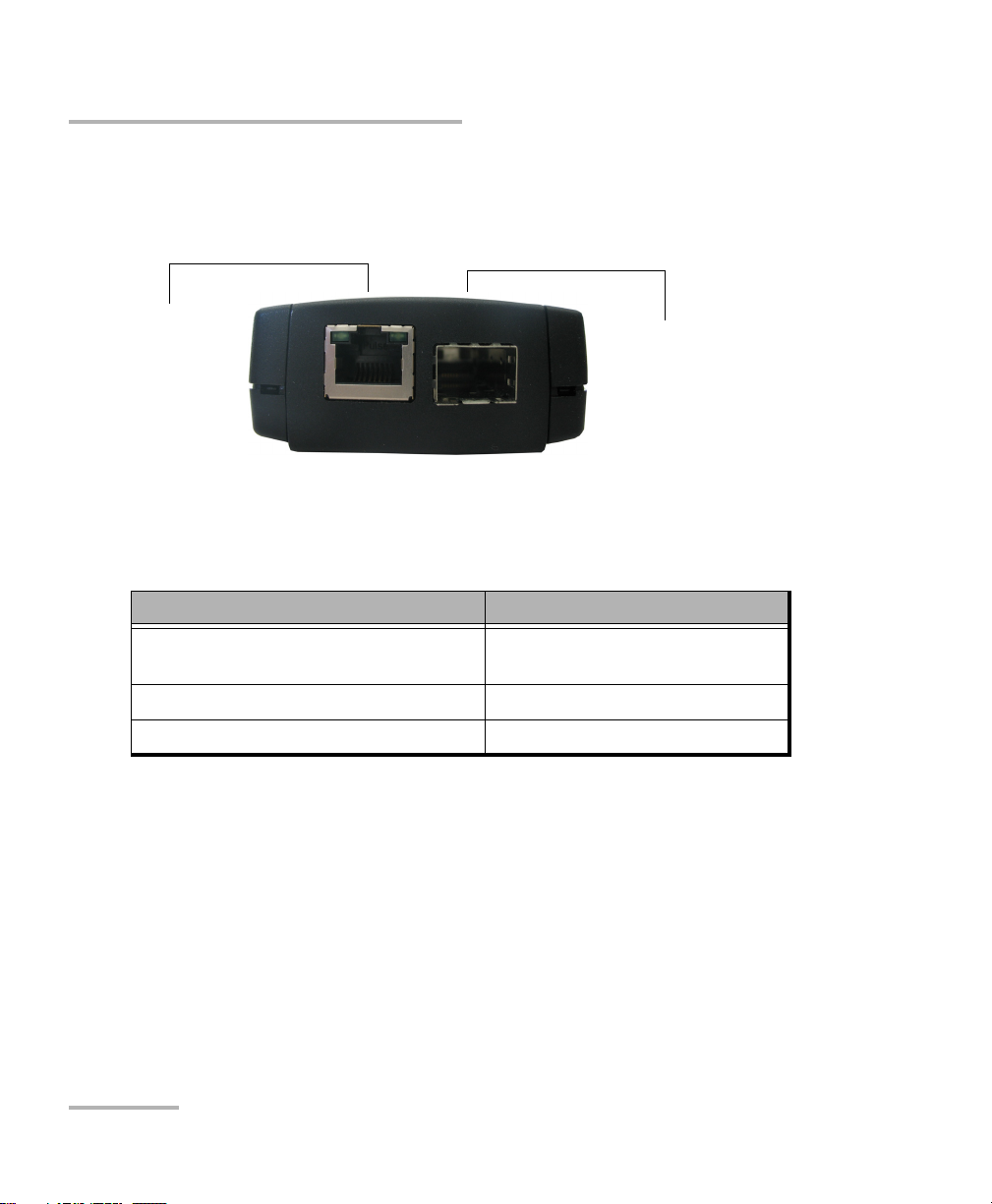
10/100/1000 Mbps
Electrical with RJ-45
connector
1000 Mbps Optical with
SFP connector
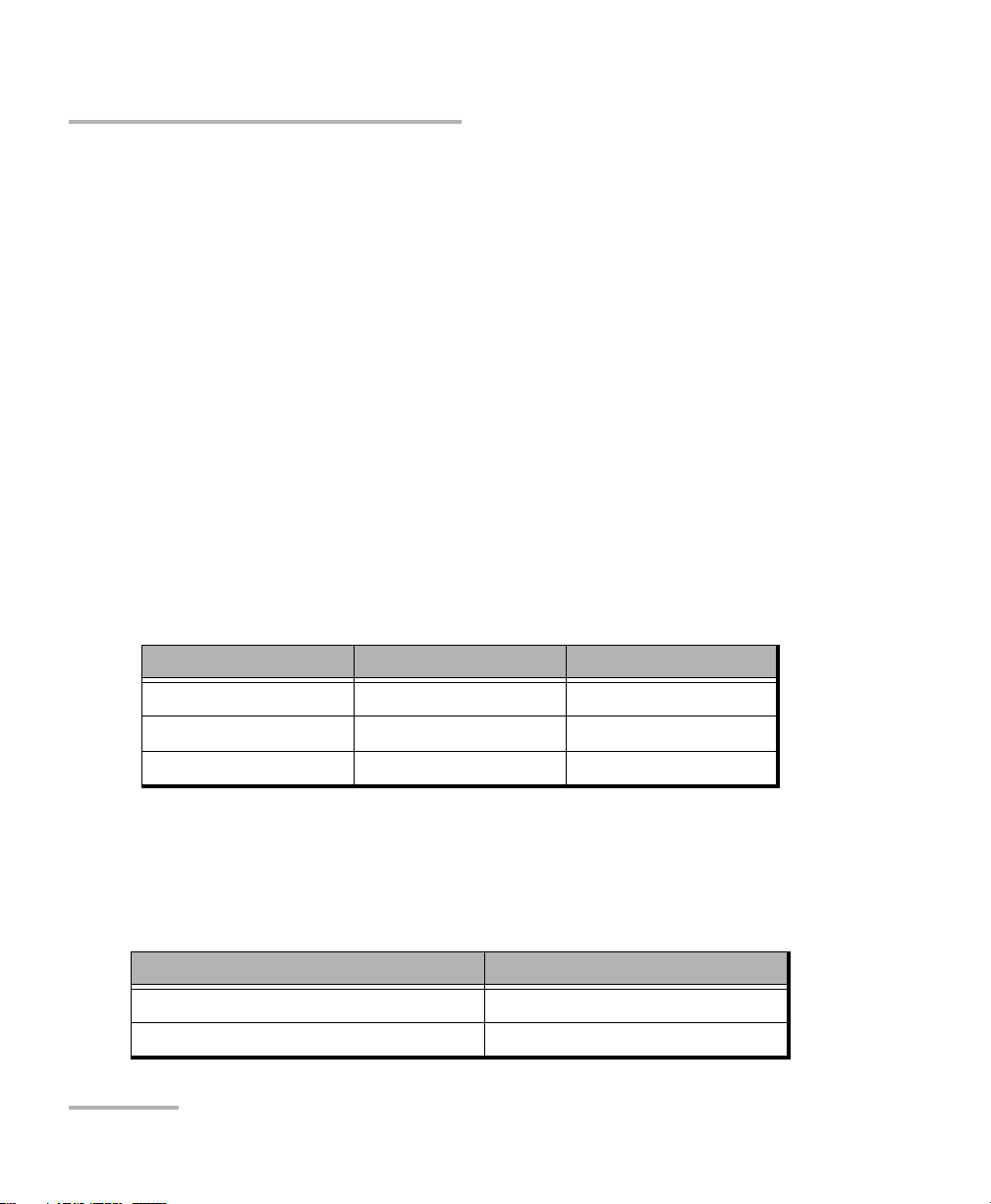
External Connectors
External Connectors
You unit is equipped with the communication ports shown below:
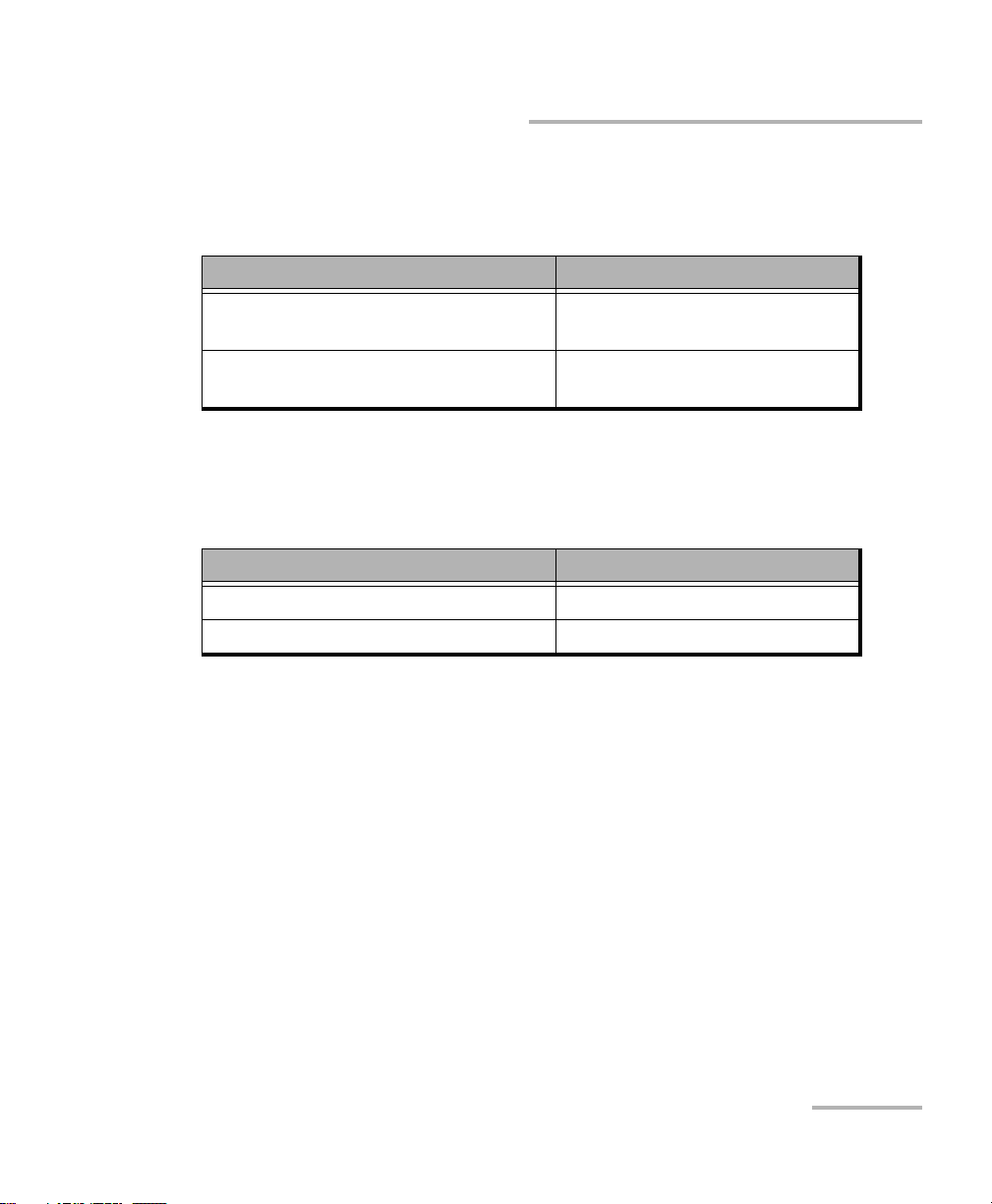
Unit connectors and equipment to be connected are described in the table
below.
Description Connected Equipment
RJ-45 connector to connect to the
Ethernet cable
tested network or equipment
SFP-module connectors SFP-module
External power unit connector Power supply unit
4 ETS-1000L
Page 11
Introducing the ETS-1000L
Conventions
Before using the product described in this guide, you should understand
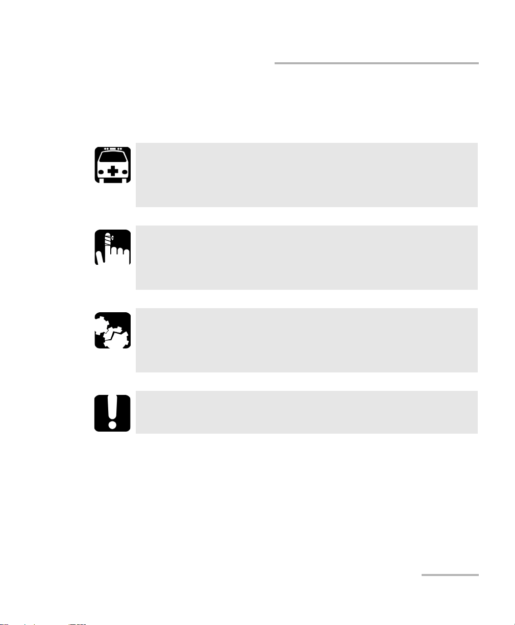
the following conventions:
WARNING
Indicates a potentially hazardous situation which, if not avoided,
could result in death or serious injury. Do not proceed unless you
understand and meet the required conditions.
CAUTION
Indicates a potentially hazardous situation which, if not avoided,
may result in minor or moderate injury. Do not proceed unless you
understand and meet the required conditions.
CAUTION
Indicates a potentially hazardous situation which, if not avoided,
may result in component damage. Do not proceed unless you
understand and meet the required conditions.
Conventions
IMPORTANT
Refers to information about this product you should not overlook.
Ethernet Tester Analyzer 5
Page 12

Page 13
2 Safety Information
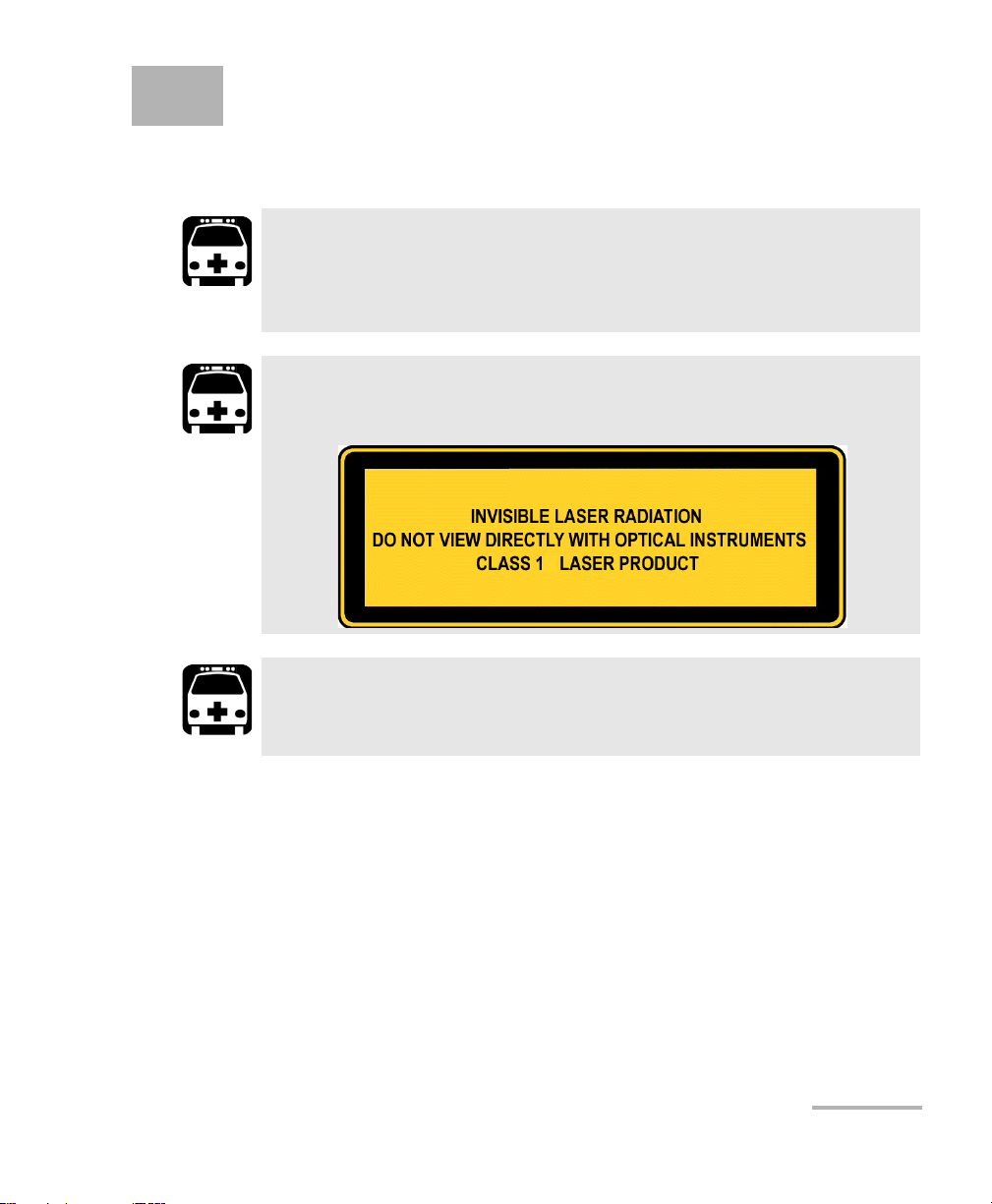
Laser Safety Warnings
WARNING
Do not install or terminate fibers while a laser source is active.
Never look directly into a live fiber, and ensure that your eyes are
protected at all times.
WARNING
This product may employ pluggable SFP lasers.a Class 1.
WARNING
When the LASER LED is on, the ETS-1000L is receiving/emitting an
optical signal.
Ethernet Tester Analyzer 7
Page 14

Safety Information
Installation Instructions Warnings
Installation Instructions Warnings
No user serviceable parts are contained inside. Contact the
manufacturer regarding service of this equipment.
All wiring and installation must be in accordance with local building
and electrical codes acceptable to the authorities in the countries
where the equipment is installed and used.
Electrostatic Discharge (ESD) Sensitive Equipment:
To minimize the risk of damage, dissipate static electricity by
touching a grounded unpainted metal object
CAUTION
IMPORTANT
CAUTION
before connecting or disconnecting cables to/from the module.
before inserting or removing SFPs to/from the analyzer.
IMPORTANT
Unauthorized modifications to this equipment shall void the user’s
authority to operated this equipment.
Laser
Class 1 laser product.
This product complies with IEC 60825-1 and 21 CFR 1040.10 except for
deviations pursuant to Laser Notice No. 50, dated July 26, 2001.
8 ETS-1000L
Page 15

3 Getting Started
Before configuring and performing tests on the ETS-1000L analyzer, turn
the unit on.
To turn the unit on:
1. Get the unit from the box and make the external inspection.
2. Connect the power supply unit to the electric network (if you use
mains voltage 110-240 V with 50/60 Hz frequency) and to the
ETS-1000L.
The unit is ready in 15 second.
3. To turn off the unit switch off the power supply unit.
Note: if you want to restore default settings of the unit hold the button of a loop’s
level choice (L) for 5 seconds. Three LEDs will flash once for a second to
inform you.
Ethernet Tester Analyzer 9
Page 16

Page 17
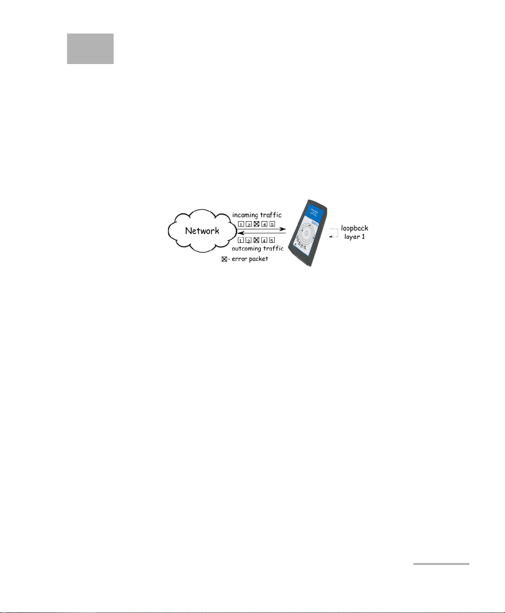
4 Loopback
The Loopback function is necessary for networks testing in compliance
with the RFC 2544, as well as for a number of other tasks. This function
allows to test the network without changing it’s settings.
Network testing with the Loopback function can be performed at the four
OSI layers, jumbo frames are supported (up to 9600 bytes).
At the Physical layer (L1) all the incoming traffic is being retransmitted
backward without changing.
All the connection schemes use the following notation:
MAC Src: indicates the source MAC address
MAC Dst: indicates the destination MAC address
IP Src: indicates the source IP address
IP Dst: indicates the destination IP address
TCP/UDP Dst: indicates the destination TCP/UDP port number
TCP/UDP Src: indicates the source TCP/UDP port number
Ethernet Tester Analyzer 11
Page 18

Loopback
At the Data link layer (L2), the incoming traffic (frames without errors)
is being retransmitted backward with swapping destination and source
MAC addresses.
Note: Frames with destination MAC address different than MAC address of
ETS-1000L are not retransmitted.
Note: Frames with equal destination and source MAC address are not
retransmitted at the data link, network and transport layers.
At the Network layer (L3) the incoming traffic (packets without errors)
is being retransmitted backward with source and destination IP and
MAC addresses swapping.
Note: Only frames with destination MAC address and destination IP address
corresponding to MAC and IP addresses of the ETS-1000L are retransmitted.
12 ETS-1000L
Page 19
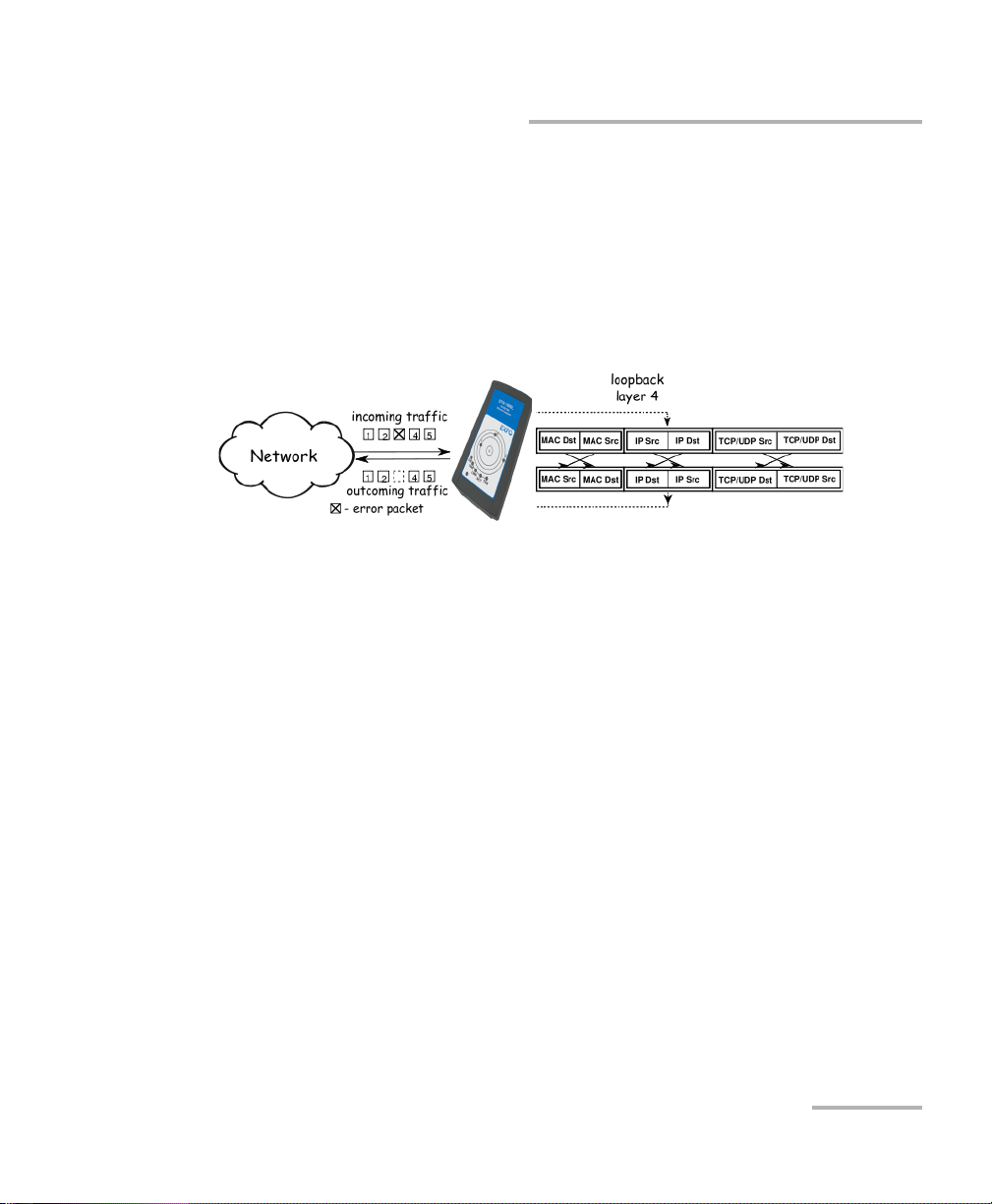
Loopback
Loopback Adjustment
At the Transport layer (L4) the incoming traffic (packets without errors)
is being retransmitted backward with source and destination IP and
MAC addresses swapping and source and destination TCP/UDP
addresses swapping.
Note: Only frames with destination MAC address and destination IP address
corresponding to MAC and IP addresses of the ETS-1000L are retransmitted.
Loopback Adjustment
Connect the ETS-1000L to the Ethernet network and select Loopback layer
by pressing L button. Additional parameters (IP address, MAC address,
etc.) are being configured using the remote management (see Remote
Management on page 15).
Ethernet Tester Analyzer 13
Page 20

Page 21

5 Remote Management
Telnet (Telecommunication Network) is a network protocol used to access
a remote unit through a personal computer. By means of the commands
presented in the tables below, it is possible to configure the ETS-1000L and
view its current settings.
To manage unit over Telnet protocol connect ETS-1000L to personal
computer through the Ethernet interface. Loopback must be turned off.
Default IP address of the loopback unit is 192.168.1.1.
Username — admin
Default password — admin.
Ethernet Tester Analyzer 15
Page 22

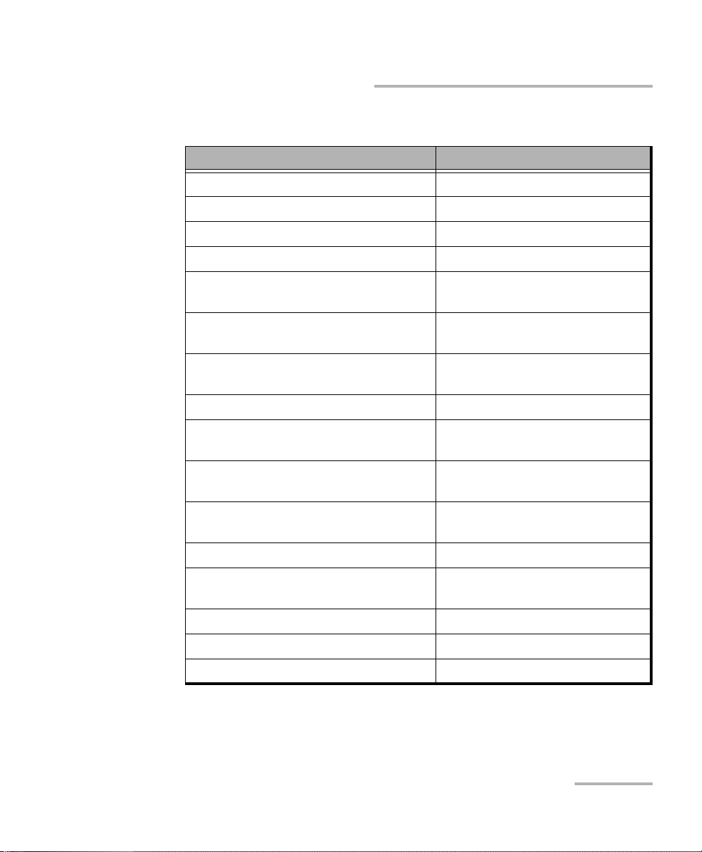
Remote Management
Remote management commands - show mode
Command Information shown in the
show version software versions
show link the state of the interface
show ip address interface IP address
show ip netmask interface subnet mask
show ip gateway gateway IP address
show mac interface MAC address
show gbe speed interface speed
show gbe autonegotiation interface autonegotiation state
show gbe mac interface MAC address
show oam mode OAM mode: off/active/passive
console or action
performed
show oam discovery state of OAM discovery process
show tftp state of a TFTP server: on/off
show vlan mode vlan state: on/off
show vlan id vlan identifier
show vlan priority vlan priority
reboot reboot unit
configure switch to configuration mode
exit finish session
help list of available commands
16 ETS-1000L
Page 23
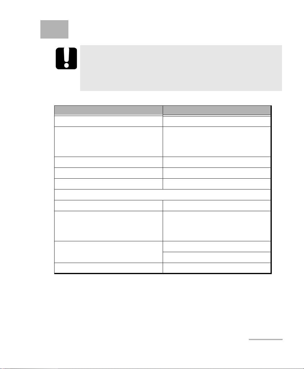
Remote Management
Remote management commands (Telnet) - configuration mode
Command Operation
ip address set interface IP address
ip netmask set interface subnet mask
ip gateway set gateway IP address
gbe mac set interface MAC address
gbe speed set interface speed:
10/100/1000/automatic
gbe autonegotiation set autonegotiation mode:
on/off
oam set OAM mode:
off/active/passive
vlan mode set vlan mode: on/off
vlan id set vlan identifier (a number in
the 0–4095 range)
vlan priority set vlan priority (a number in
the 0–7 range)
tftp enable or disable TFTP server:
on/off
password change admin’s password
save save settings; settings will be
applied after unit reboot
reboot reboot unit
exit leave configuration mode
help list of accessible commands
Note: Configuration mode commands become effective after save and reboot
commands.
Ethernet Tester Analyzer 17
Page 24

Remote Management
OAM
OAM
OAM (Operations, Administration, and Maintenance) is a protocol of the
link state monitoring. The protocol operates at the Data Link Layer of OSI
model. To transmit data between two Ethernet-units, OAM protocol data
units (OAMPDU) are used.
An important feature of the OAM protocol is to provide the ability to use
Loopback mode for the remote end. Both units should support the IEEE
802.3ah standard.
ETS-1000L and remote unit should be connected directly. Possible OAM
states are described below.
Passive: In passive mode, the port can only response to Ethernet OAM
commands from the remote unit, but cannot initiate the Loopback
mode.
Off: OAM is disabled.
18 ETS-1000L
Page 25

Remote Management
Upgrading Versions of the Software
Upgrading Versions of the Software
To upgrade to the latest versions of software:
1. Establish connection with the unit over Telnet protocol. Provide user
name and password.
2. Enable TFTP server (tftp on command in configure mode).
If you use Linux operating system:
1. Configure TFTP client for a work in binary mode (mode binary
command).
2. Connect to the unit by means of TFTP client (connect IP-address of
unit command).
3. Upload software package file with the new version of software (put
path-to-file/image X.X.X.fs).
If you use Windows operating system:
1. Install tftp client on yor PC (WinAgents TFTP Client for example).
2. Enter in console terminal.
tftp.exe -i 192.168.1.1 put C:\work\image_X.X.X.fs
When the software package file is uploaded ETS-1000L will automatically
reboot.
Note: If current and new versions of the software are too different, default
settings are restored.
Note: If current and new versions of the software are too different, default
settings are restored. In case of unsuccessful upgrade, the functionality of
the unit may be restored. Hold the L button for 5 seconds while turning on
the power. Normal operation will be restored within 1 minute.
Ethernet Tester Analyzer 19
Page 26

Page 27

6 Maintenance
To help ensure long, trouble-free operation:
Always inspect fiber-optic connectors before using them and clean
them if necessary.
Keep the unit free of dust.
Clean the unit casing and front panel with a cloth slightly dampened
with water.
Store unit at room temperature in a clean and dry area. Keep the unit
out of direct sunlight.
Avoid high humidity or significant temperature fluctuations.
Avoid unnecessary shocks and vibrations.
If any liquids are spilled on or into the unit, turn off the power
immediately, disconnect from any external power source, remove the
batteries and let the unit dry completely.
The use of controls, adjustments and procedures, namely for
operation and maintenance, other than those specified herein may
result in hazardous radiation exposure or impair the protection
provided by this unit.
WARNING
Ethernet Tester Analyzer 21
Page 28

Maintenance
Recycling and Disposal (Applies to European Union Only)
Recycling and Disposal
(Applies to European Union Only)
For complete recycling/disposal information as per European Directive
WEEE 2012/19/UE, visit the EXFO Web site at www.exfo.com/recycle.
22 ETS-1000L
Page 29

7 Troubleshooting
Solving Common Problems
Before calling EXFO’s technical support, please read the following
common problems that can occur and their respective solution.
Problem Possible Cause Solution
Connection is lost Incorrect cable
connection
Two active connections
at the same time
No Connection
No Telnet Connection
Internet connection
settings
Loopback mode is on,
incorrect cable
connection
Check cable connection
state
Use only one active
connection
Check autonegotiation
mode state and
interface settings
Turn off Loopback mode
and check cable
connection state
Ethernet Tester Analyzer 23
Page 30

Troubleshooting
Contacting the Technical Support Group
Contacting the Technical Support Group
To obtain after-sales service or technical support for this product, contact
EXFO at one of the following numbers. The Technical Support Group is
available to take your calls from Monday to Friday, 8:00 a.m. to 7:00 p.m.
(Eastern Time in North America).
Technical Support Group
400 Godin Avenue
Quebec (Quebec) G1M 2K2
CANADA
For detailed information about technical support, and for a list of other
worldwide locations, visit the EXFO Web site at www.exfo.com.
If you have comments or suggestions about this user documentation, you
can send them to customer.feedback.manual@exfo.com.
To accelerate the process, please have information such as the name and
the serial number (see the product identification label), as well as a
description of your problem, close at hand.
1 866 683-0155 (USA and Canada)
Tel.: 1 418 683-5498
Fax: 1 418 683-9224
support@exfo.com
24 ETS-1000L
Page 31

Troubleshooting
Transportation
Transportation
Maintain a temperature range within specifications when transporting the
unit. Transportation damage can occur from improper handling. The
following steps are recommended to minimize the possibility of damage:
Pack the unit in its original packing material when shipping.
Avoid high humidity or large temperature fluctuations.
Keep the unit out of direct sunlight.
Avoid unnecessary shocks and vibrations.
Ethernet Tester Analyzer 25
Page 32

Page 33

8 Warranty
General Information
EXFO Inc. (EXFO) warrants this equipment against defects in material and
workmanship for a period of one year from the date of original shipment.
EXFO also warrants that this equipment will meet applicable specifications
under normal use.
During the warranty period, EXFO will, at its discretion, repair, replace,
or issue credit for any defective product, as well as verify and adjust the
product free of charge should the equipment need to be repaired or if the
original calibration is erroneous. If the equipment is sent back for
verification of calibration during the warranty period and found to meet all
published specifications, EXFO will charge standard calibration fees.
The warranty can become null and void if:
unit has been tampered with, repaired, or worked upon by
unauthorized individuals or non-EXFO personnel.
warranty sticker has been removed.
IMPORTANT
case screws, other than those specified in this guide, have been
removed.
case has been opened, other than as explained in this guide.
unit serial number has been altered, erased, or removed.
unit has been misused, neglected, or damaged by accident.
THIS WARRANTY IS IN LIEU OF ALL OTHER WARRANTIES EXPRESSED,
IMPLIED, OR STATUTORY, INCLUDING, BUT NOT LIMITED TO, THE
IMPLIED WARRANTIES OF MERCHANTABILITY AND FITNESS FOR A
PARTICULAR PURPOSE. IN NO EVENT SHALL EXFO BE LIABLE FOR
SPECIAL, INCIDENTAL, OR CONSEQUENTIAL DAMAGES.
Ethernet Tester Analyzer 27
Page 34

Warranty
Liability
Liability
EXFO shall not be liable for damages resulting from the use of the product,
nor shall be responsible for any failure in the performance of other items to
which the product is connected or the operation of any system of which
the product may be a part.
EXFO shall not be liable for damages resulting from improper usage or
unauthorized modification of the product, its accompanying accessories
and software.
28 ETS-1000L
Page 35

Warranty
Exclusions
EXFO reserves the right to make changes in the design or construction of
any of its products at any time without incurring obligation to make any
changes whatsoever on units purchased. Accessories, including but not
limited to fuses, pilot lamps, batteries and universal interfaces (EUI) used
with EXFO products are not covered by this warranty.
This warranty excludes failure resulting from: improper use or installation,
normal wear and tear, accident, abuse, neglect, fire, water, lightning or
other acts of nature, causes external to the product or other factors beyond
the control of EXFO.
IMPORTANT
In the case of products equipped with optical connectors, EXFO will
charge a fee for replacing connectors that were damaged due to
misuse or bad cleaning.
Certification
Exclusions
EXFO certifies that this equipment met its published specifications at the
time of shipment from the factory.
Ethernet Tester Analyzer 29
Page 36

Warranty
Service and Repairs
Service and Repairs
EXFO commits to providing product service and repair for five years
following the date of purchase.
To send any equipment for service or repair:
1. Call one of EXFO’s authorized service centers (see EXFO Service
2. If equipment must be returned to EXFO or an authorized service
3. If possible, back up your data before sending the unit for repair.
4. Pack the equipment in its original shipping material. Be sure to include
5. Return the equipment, prepaid, to the address given to you by support
Centers Worldwide on page 31). Support personnel will determine if
the equipment requires service, repair, or calibration.
center, support personnel will issue a Return Merchandise
Authorization (RMA) number and provide an address for return.
a statement or report fully detailing the defect and the conditions under
which it was observed.
personnel. Be sure to write the RMA number on the shipping slip. EXFO
will refuse and return any package that does not bear an RMA number.
Note: A test setup fee will apply to any returned unit that, after test, is found to
meet the applicable specifications.
After repair, the equipment will be returned with a repair report. If the
equipment is not under warranty, you will be invoiced for the cost
appearing on this report. EXFO will pay return-to-customer shipping costs
for equipment under warranty. Shipping insurance is at your expense.
Routine recalibration is not included in any of the warranty plans. Since
calibrations/verifications are not covered by the basic or extended
warranties, you may elect to purchase FlexCare Calibration/Verification
Packages for a definite period of time. Contact an authorized service center
(see EXFO Service Centers Worldwide on page 31).
30 ETS-1000L
Page 37

Warranty
EXFO Service Centers Worldwide
EXFO Service Centers Worldwide
If your product requires servicing, contact your nearest authorized service
center.
EXFO Headquarters Service Center
400 Godin Avenue
Quebec (Quebec) G1M 2K2
CANADA
EXFO Europe Service Center
Winchester House, School Lane
Chandlers Ford, Hampshire S053 4DG
ENGLAND
EXFO Telecom Equipment
(Shenzhen) Ltd.
3rd Floor, Building 10,
Yu Sheng Industrial Park (Gu Shu
Crossing), No. 467,
National Highway 107,
Xixiang, Bao An District,
Shenzhen, China, 518126
1 866 683-0155 (USA and Canada)
Tel.: 1 418 683-5498
Fax: 1 418 683-9224
support@exfo.com
Tel.: +44 2380 246800
Fax: +44 2380 246801
support.europe@exfo.com
Tel: +86 (755) 2955 3100
Fax: +86 (755) 2955 3101
support.asia@exfo.com
Ethernet Tester Analyzer 31
Page 38

Page 39
ASpecifications
IMPORTANT
The following technical specifications can change without notice.
The information presented in this section is provided as a reference
only. To obtain this product’s most recent technical specifications,
visit the EXFO Web site at www.exfo.com.
Specifications Values
Ingress protection IPX0
Weight of Equipment:
Analyzer
AC adapter
Operational Temp 5C to 40C (according to safety report)
Humidity 90 % max
Storage -20 to 35
Internal Battery (qty 4) specs (Refer spec sheet below)
Storage -20 to 30
0.64 kg
0.2 kg
o
C
o
C
AC adapter:
Input
Output
Pollution Degree 2 (when plugged to AC mains)
Max operating altitude 2000 m
a. Not exceeding +/- 10 % of the nominal voltage.
b. For indoor use only
c. Equipment normally protected against exposure to direct sunlight, precipitations and full wind
pressure.
Ethernet Tester Analyzer 33
100-240VAC
DC 11-13V 1.63-1.38A
3 (when operated from batteries)
a
50/60Hz 0.5A
b
c
Page 40

Page 41

B Bibliography
[1] IEEE Std 802.1Q, IEEE Standard for Local and metropolitan area
net-works — Virtual Bridged Local Area Networks.
RFC 791, Postel, J., Internet Protocol, DARPA, September 1981.
RFC 826, Plummer, D., Ethernet Address Resolution Protocol or converting
network protocol addresses to 48.bit Ethernet address for transmission on
Ethernet hardware, November 1982.
RFC 1349, Almquist, P., Type of Service in the Internet Protocol Suite, July
1992.
RFC 2544, Benchmarking Methodology for Network Interconnect Devices,
S. Bradner and J. McQuaid, March 1999.
RFC 4689, Terminology for Benchmarking Network-layer Traffic Control
Mechanisms, S. Poretsky, October 2006.
ITU-T O.150 (05/96), General requirements for instrumentation for
perfomance measurements on digital transmission equipment.
IEEE 802.3ah, Ethernet in the First Mile Task Force.
Ethernet Tester Analyzer 35
Page 42

Page 43

Index
Index
A
ACT ............................................................... 3
after-sales service ........................................ 24
C
caution
of personal hazard................................... 5
of product hazard.................................... 5
CE............................................................. iii, iv
class 1 ........................................................... 7
cleaning
front panel............................................. 21
configuration mode .................................... 17
conventions, safety ....................................... 5
customer service.......................................... 30
D
data link layer.............................................. 12
E
equipment returns ...................................... 30
ESD................................................................ 8
Ethernet ........................................................ 1
External connectors....................................... 4
F
FCC................................................................iii
FDX ............................................................... 3
Front ............................................................. 1
front panel, cleaning ................................... 21
I
IC.................................................................. iii
identification label....................................... 24
IP Dst ........................................................... 11
IP Src ........................................................... 11
L
label, identification...................................... 24
laser........................................................... 7, 8
LED
laser ......................................................... 7
LEDs............................................................... 2
Link
................................................................ 2
Speed....................................................... 2
Loopback................................................. 1, 11
loopback...................................................... 11
Loopback Adjustment.................................. 13
Loopback Control .......................................... 2
loopback layer ............................................... 2
M
MAC Dst ...................................................... 11
MAC Src....................................................... 11
maintenance................................................ 21
front panel............................................. 21
general information ............................... 21
N
Network ...................................................... 12
O
OAM............................................................ 18
Ethernet Tester Analyzer 37
Page 44

Index
P
Physical layer ............................................... 11
Power............................................................ 3
power supply ................................................ 9
product
identification label................................. 24
specifications......................................... 33
R
return merchandise authorization (RMA) .... 30
S
safety
caution .................................................... 5
conventions ............................................. 5
laser......................................................... 7
warning ................................................... 5
service and repairs....................................... 30
service centers............................................. 31
shipping to EXFO ........................................ 30
show mode ................................................. 16
specifications, product ................................ 33
storage requirements .................................. 21
symbols, safety.............................................. 5
W
warranty...................................................... 27
certification............................................ 29
exclusions .............................................. 29
general................................................... 27
liability ................................................... 28
null and void.......................................... 27
T
TCP/UDP Dst ................................................ 11
TCP/UDP Src ................................................ 11
technical specifications ............................... 33
technical support ........................................ 24
temperature for storage.............................. 21
Transport..................................................... 13
transportation requirements ................. 21, 25
troubleshooting .......................................... 23
38 ETS-1000L
Page 45

抩⛙
CHINESE REGULATION ON RESTRICTION OF HAZARDOUS SUBSTANCES
₼⦌␂ℝ☀⹂䓸德棟Ⓟ䤓屓⸩
NAMES AND CONTENTS OF THE TOXIC OR HAZARDOUS SUBSTANCES OR ELEMENTS
CONTAINED IN THIS EXFO PRODUCT
▔⚺⦷㦻 EXFO ℶ❐₼䤓㦘㹡㦘⹂䓸德㒥⏒侯䤓⚜䱿✛⚺摞
O
Indicates that this toxic or hazardous substance contained in all of the homogeneous
materials for this part is below the limit requirement in SJ/T11363-2006
嫷䯉年㦘㹡㦘⹂䓸德⦷年捷ↅ㓏㦘⧖德㧟㠨₼䤓⚺摞⧖⦷ SJ/T11363-2006 㪖屓⸩䤓
棟摞尐㻑ⅴₚᇭ
X
Indicates that this toxic or hazardous substance contained in at least one of the homogeneous
materials used for this part is above the limit requirement in SJ/T11363-2006
嫷䯉年㦘㹡㦘⹂䓸德咂⺠⦷年捷ↅ䤓㩟⧖德㧟㠨₼䤓⚺摞怔⒉ SJ/T11363-2006 㪖
屓⸩䤓棟摞尐㻑ᇭ
Part Name
捷ↅ⚜䱿
Toxic or hazardous Substances and Elements
㦘㹡㦘⹂䓸德✛⏒侯
Lead
杔
(Pb)
Mercury
㻭
(Hg)
Cadmium
椣
(Cd)
Hexavalent
Chromium
⏼ↆ杻
(Cr VI)
Pol yb ro mi na te d
biphenyls
⮩䅃勣啾
(PBB)
Polybrominated
diphenyl ethers
⮩䅃ℛ啾搩
(PBDE)
Enclosure
⮥⮂
OO O O O O
Electronic and
electrical
sub-assembly
䟄✛䟄兓ↅ
XO X O X X
Optical
sub-assembly
a
⏘ⷵ兓ↅ
a
a. If applicable.
Ⱁ㨫抑䞷ᇭ
XO O O O O
Mechanical
sub-assembly
a
㧉㬿兓ↅ
a
OO O O O O
NOTICE
抩⛙
CHINESE REGULATION ON RESTRICTION OF HAZARDOUS SUBSTANCES
₼⦌␂ℝ☀⹂䓸德棟Ⓟ䤓屓⸩
NAMES AND CONTENTS OF THE TOXIC OR HAZARDOUS SUBSTANCES OR ELEMENTS
CONTAINED IN THIS EXFO PRODUCT
▔⚺⦷㦻 EXFO ℶ❐₼䤓㦘㹡㦘⹂䓸德㒥⏒侯䤓⚜䱿✛⚺摞
O
Indicates that this toxic or hazardous substance contained in all of the homogeneous
materials for this part is below the limit requirement in SJ/T11363-2006
嫷䯉年㦘㹡㦘⹂䓸德⦷年捷ↅ㓏㦘⧖德㧟㠨₼䤓⚺摞⧖⦷ SJ/T11363-2006 㪖屓⸩䤓
棟摞尐㻑ⅴₚᇭ
X
Indicates that this toxic or hazardous substance contained in at least one of the homogeneous
materials used for this part is above the limit requirement in SJ/T11363-2006
嫷䯉年㦘㹡㦘⹂䓸德咂⺠⦷年捷ↅ䤓㩟⧖德㧟㠨₼䤓⚺摞怔⒉ SJ/T11363-2006 㪖
屓⸩䤓棟摞尐㻑ᇭ
Part Name
捷ↅ⚜䱿
Toxic or hazardous Substances and Elements
㦘㹡㦘⹂䓸德✛⏒侯
Lead
杔
(Pb)
Mercury
㻭
(Hg)
Cadmium
椣
(Cd)
Hexavalent
Chromium
⏼ↆ杻
(Cr VI)
Pol yb ro mi na te d
biphenyls
⮩䅃勣啾
(PBB)
Polybrominated
diphenyl ethers
⮩䅃ℛ啾搩
(PBDE)
Enclosure
⮥⮂
OO O O O O
Electronic and
electrical
sub-assembly
䟄✛䟄兓ↅ
XO X O X X
Optical
sub-assembly
a
⏘ⷵ兓ↅ
a
a. If applicable.
Ⱁ㨫抑䞷ᇭ
XO O O O O
Mechanical
sub-assembly
a
㧉㬿兓ↅ
a
OO O O O O
Page 46

MARKING REQUIREMENTS
㪖㽷尐㻑
Product
ℶ❐
Environmental protection use period (years)
䘾⬒≬㔳∎䞷㦮棟 ( )
Logo
㪖㉦
This Exfo product
㦻 EXFO ℶ❐
10
Battery
a
䟄㻯
a
If applicable.
Ⱁ㨫抑䞷ᇭ
5
MARKING REQUIREMENTS
㪖㽷尐㻑
Product
ℶ❐
Environmental protection use period (years)
䘾⬒≬㔳∎䞷㦮棟 ( )
Logo
㪖㉦
This Exfo product
㦻 EXFO ℶ❐
10
Battery
a
䟄㻯
a
a. If applicable.
Ⱁ㨫抑䞷ᇭ
5
Page 47

P/N: 1066206
www.EXFO.com · info@exfo.com
CORPORATE HEADQUARTERS 400 Godin Avenue Quebec (Quebec) G1M 2K2 CANADA
Tel.: 1 418 683-0211 · Fax: 1 418 683-2170
EXFO AMERICA 3400 Waterview Parkway Suite 100 Richardson, TX 75080 USA
EXFO EUROPE Winchester House,
EXFO ASIA-PACIFIC 62 Ubi Road 1,
EXFO CHINA Beijing Global Trade Center, Tower C,
EXFO SERVICE ASSURANCE 270 Billerica Road Chelmsford MA, 01824 USA
EXFO FINLAND Elektroniikkatie 2 FI-90590 Oulu, FINLAND
TOLL-FREE (USA and Canada) 1 800 663-3936
© 2014 EXFO Electro-Optical Engineering Inc. All rights reserved.
Printed in Canada (2014-04)
School Lane
#09-01/02 Oxley Bizhub 2
Room 1207, 36 North Third Ring Road
East, Dongcheng District
Tel.: 1 972-761-927 · Fax: 1 972-761-9067
Chandlers Ford, Hampshire S053 4DG ENGLAND
Tel.: +44 2380 246 800 · Fax: +44 2380 246 801
SINGAPORE 408734
Tel.: +6563338241 · Fax: +6563338242
Beijing 100013 P. R. CHINA
Tel.: +86 (10) 5825 7755 · Fax: +86 (10) 5825 7722
Tel.: 1 978 367-5600 · Fax: 1 978 367-5700
Tel.: +358 (0) 403 010 300 · Fax: +358 (0) 8 564 5203
 Loading...