


Speed Dome
EPTZ3000/EPTZ3000I
USER MANUAL
Date: Nov 2008
Table of Contents
1. EPTZ3000/EPTZ3000I OVERVIEW.................................................... |
1-3 |
||
1.1. |
Introduction ............................................................................................. |
1-3 |
|
1.2. |
Specifications .......................................................................................... |
1-5 |
|
1.3. |
Feature ..................................................................................................... |
1-7 |
|
|
1.3.1. |
Profile of EPTZ3000/EPTZ3000I........................................................ |
1-7 |
|
1.3.2. |
EPTZ3000/EPTZ3000I Base Board ................................................... |
1-8 |
|
1.3.3. |
EPTZ3000/EPTZ3000I Control Board................................................ |
1-9 |
1.4. |
EPTZ3000/EPTZ3000I Connection ....................................................... |
1-10 |
|
1.5.EPTZ3000/EPTZ3000I Quick Operation Guide (Work with EKB500) .1-11
2. EPTZ3000/EPTZ3000I INSTALLATION ........................................... |
2-12 |
||
2.1. |
Packing List ........................................................................................... |
2-12 |
|
2.2. |
Cable Needed......................................................................................... |
2-12 |
|
2.3. |
Initial Setup ............................................................................................ |
2-13 |
|
|
2.3.1. |
Address Setting................................................................................ |
2-14 |
|
2.3.2. |
Communication Protocol Setting ...................................................... |
2-17 |
|
2.3.3. Transmission Speed Setting (Baud Rate Setting) ............................ |
2-17 |
|
2.4. |
Rack and Speed Dome Installation ...................................................... |
2-19 |
|
|
2.4.1. |
Installation Requirements................................................................. |
2-19 |
|
2.4.2. EPTZ3000 Dome Camera Wall Mount Installation ........................... |
2-19 |
|
|
2.4.3. EPTZ3000I Dome Camera Installation............................................. |
2-22 |
|
2.5. |
Accessories ........................................................................................... |
2-25 |
|
|
2.5.1. EPTZ-CPMA: Ceiling Pendant Mount Adapter ................................. |
2-25 |
|
|
2.5.2. |
EPTZ-PMA: Pole Mount Adapter...................................................... |
2-25 |
|
2.5.3. |
EPTZCMA: Corner Mount Adapter................................................. |
2-25 |
1-1
3. EPTZ3000/EPTZ3000I CAMERA SETUP MENU ............................. |
3-27 |
|
3.1. |
Structure of the Setup Menu ................................................................ |
3-27 |
|
3.1.1. Camera Setup Menu ........................................................................ |
3-28 |
4. EPTZ3000/3000I FUNCTION SETUP AND OPERATION ................ |
4-36 |
|
4.1. |
Manual Control Mode ............................................................................ |
4-36 |
4.2. |
Auto Pan Mode ...................................................................................... |
4-36 |
4.3. |
Position Setting ..................................................................................... |
4-37 |
4.4. |
Tour Mode .............................................................................................. |
4-38 |
4.5. |
Alarm Link to a Position/Tour............................................................... |
4-39 |
4.6. |
Other operations ................................................................................... |
4-40 |
APPENDIX : The Alarm I/O Connection ............................................... |
4-41 |
|
1-2
1. EPTZ3000/EPTZ3000I OVERVIEW
1.1. Introduction
EPTZ3000/EPTZ3000I, an intelligent high-speed dome camera is ready to secure your property with its omni-directional and exact monitoring. A 30X optical and 8X digital zoom combining with a high-performance chip makes captured images clear and vivid. The other powerful camera functions EPTZ3000/EPTZ3000I equips with:
Wide Dynamic makes objects clear in a high illumination background.
Vertical double density interline CCD with a slower shutter and true Day/Night function.
Electronics flip, no mechanical flip is necessary.
520 color/570 B&W TVL; PAL/NTSC image formats support.
Auto and fast focus increases the searching speed and precision.
Auto Iris adjusts the monitoring image to the best brightness.
White Balance function makes the shades of color more natural in different light conditions.
Color / B&W images auto switching to enhance the sensitivity in a low light condition or at night.
Private zone protects your privacy.
1-3
Furthermore, the micro control unit enables camera a nimble and exact movement
from minimal 0.01°/sec to maximal 360°/sec. It can go to every preset position in 1
second. It also has other advantages such as:
192 preset positions are available.
16 cruise tours can be set, and each tour contains up to 16 positions.
Up to 256 speed domes can be supported on a RS-485 bus when all speed domes are controlled by keyboard EKB500.
Auto heater and fan to fit all kinds of temperature (outdoor models).
Built-in 4 alarm inputs and 1 alarm output.
All of the features make the intelligent high-speed dome camera works for a wide range and demanding application such as banks, airports, stations, casinos, streets of cities, intelligent buildings, and etc.
1-4
1.2. Specifications
Model |
EPTZ3000 (outdoor) |
|
|
EPTZ3000I (indoor) |
|
|
|
||
Pickup Device |
1/4'' Vertical double density interline CCD |
|||
|
|
|
||
Video Format |
NTSC or PAL |
|
||
|
|
|||
Scanning System |
NTSC: 525 TV lines, 60 fields/sec |
|||
|
PAL: 625 TV lines, 50 fields/sec |
|||
|
|
|||
Picture Elements |
768 x 494 ( NTSC ) , 752 x 582 ( PAL ) |
|||
|
|
|||
Horizontal Resolution |
520 TVL:Color ; 570TVL:B/W |
|||
|
|
|||
Sensitivity |
0.3 Lux/F=1.6 Color ; 0.05 Lux/F=1.6 B/W |
|||
|
|
|
||
S/N Ratio |
Over 52dB |
|
||
|
|
|||
Electronic Shutter |
128x (Slow Shutter ON)~1/60~1/120,000 sec (NTSC) |
|||
|
128x (Slow Shutter ON)~1/50~1/120,000 sec (PAL) |
|||
|
|
|||
Digital Slow Shutter |
OFF/4x/8x/12x/16x/32x/64x/128x selectable |
|||
|
|
|||
Shutter Selection |
AUTO/A.FLK/Manual (x8~1/120000) selectable |
|||
|
|
|||
Lens Type |
30x optical zoom , f=3.3 mm (wide) to 99mm (tele) , F1.6 to F3.2 |
|||
|
|
|||
Zoom Ratio |
240x max ( 30x Optical and 8x Digital Zoom ) |
|||
|
|
|||
True Day/Night |
Auto/Manual ICR |
|||
|
|
|
|
|
Black Light Comp. |
|
No |
|
|
|
|
|
||
Auto Gain Control |
Auto/Manual |
|
||
|
|
|||
White Balance |
Auto Indoor/Auto Outdoor/One push/Man 2000K,3200K,5100K |
|||
|
|
selectable |
|
|
|
|
|||
Video Output |
BNC 1.0Vp-p , 75ohm |
|||
|
|
|||
Sync. Mode |
Line Lock/Internal Sync |
|||
|
|
|
|
|
Power Source |
|
24VAC |
|
|
|
|
|
||
Power Consumption |
24VAC 18W Max. ( without |
|
24VAC 18W Max. |
|
|
heater ) 18W |
|
|
|
|
24VAC 66W Max. ( with heater ) |
|
|
|
|
70W |
|
|
|
|
|
|
|
|
Operating Temperature |
-40°C~50°C ; -40°F~122°F |
|
0°C~ |
50°C ; 32°F~122°F |
|
|
|
||
Focus Control |
One push/Auto/Manual |
|||
|
|
|||
Horizontal Rotation Speed |
0.1°/s~360°/s (1-239 grade shift gears) |
|||
|
|
|||
Horizontal Rotation Range |
360° unlimited rotation |
|||
|
|
|||
Tilt Rotation Range |
180° pendulum motion |
|||
|
|
|||
Auto Zoom Speed Control |
Control speed auto-adjusted according to zoom length changing |
|||
|
|
|||
Auto Pan, 2 Points |
Can set freely |
|||
Scanning |
|
|
|
|
|
|
|||
Auto Pan Speed |
1~239 grades available |
|||
|
|
|
|
|
1-5
Dwell Time (2 points) |
1~127 seconds available |
||
|
|
|
|
Preset Positions |
128 positions |
||
|
|
|
|
Running to Position Speed |
1~239 grades available |
||
|
|
|
|
Dwell Time at Preset |
1~239 seconds available |
||
Position |
|
|
|
|
|
|
|
Tour |
16 groups |
||
|
|
|
|
Tour Point per Group |
16 preset positions |
||
|
|
|
|
Fan & Heater |
Fan & Heater auto starts |
|
No |
|
|
|
|
Position Accuracy |
±0.1° |
||
|
|
|
|
Alarm |
4 in 1 out with tour/position auto triggering |
||
|
|
|
|
Built-in Menu for |
Yes |
||
Functions |
|
|
|
|
|
|
|
Communication |
RS-485 |
||
|
|
|
|
Communication Speed |
1200/2400/4800/9600 bps |
||
|
|
|
|
Built-in Protocols |
EVF-1 ; Pelco-P ; Pelco-D ; A –type ; Plus-D |
||
|
|
|
|
Address Editable |
Yes (through DIP switch) |
||
|
|
|
|
Speed Dome Address |
0-255 |
||
|
|
|
|
Manual Pan/Tilt Speed |
Pan: 0.01º ~ 360º/s ; Tilt: 0 .01º ~ 360º/s |
||
|
|
|
|
Weatherproof Ratings |
IP66 |
|
Indoor |
|
|
|
|
Safety |
CE ; FCC |
||
|
|
|
|
Dimensions |
330mm(W) x 365mm(H) x |
|
208mm(W) x 215mm(H) x |
|
220mm(O.D) / |
|
208mm(O.D) / |
|
13"(W) x 14.4" (H) x 8.7"(O.D) |
|
8.7"(W) x 12.2" (H) x 8.7"(O.D) |
|
|
|
|
Weight |
4.2kg/9.25lbs |
|
2.15kg/4.8lbs |
|
|
|
|
1-6

1.3. Feature
1.3.1. Profile of EPTZ3000/EPTZ3000I
M5 Bolt (Hex) x3
Base PCB board
Control board
Housing
Inner Housing
M3 Bolt x3


Bulb
EPTZ3000
Wall Mount Bracket
 Connection Bus
Mechanical Part |
Camera Module |
Power Cable


 BNC Cable
RS485 Cable
EPTZ3000I
|
Power Cable |
|
Base PCB board |
BNC Cable |
|
Control board |
RS485 Cable |
|
Housing |
||
|
||
Clip |
Connection Bus |
|
Ceiling |
Mechanical Part |
|
|
Button |
Camera Module |
|
|
Bulb |
|
1-7
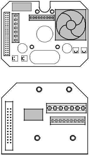
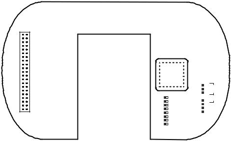
1.3.2. EPTZ3000/EPTZ3000I Base Board
The base board that is on the bottom of the housing connects to power cable, video cable, control cable, alarm cable, fan and heater. In order to connect to cables, the board needs to be taken off, and put back after finishing connecting to all cables. The connectors of cable names are marked on the board in white text. The details of the alarm connector (JP5) are shown on the APPENDIX A.
For EPTZ3000 outdoor model, JP1, JP3 and JP6 that are two-pin connectors need to be taken off during installing. JP1 and JP3 are connectors for heater, and they can be switched. JP6 is a fan controller connector that turns on/off of the fan. The 3 cables are too short to be connected to a wrong connector when putting them back.
RELAY
JP5
Video +
Video -
RS485 +
RS485 -
AC24
AC24
JP6 |
JP4 |
JP3 JP1
EPTZ3000 Baseboard
Video + |
Video - |
RS485 + |
RS485 - |
AC24 |
AC24 |
RELAY JP5
EPTZ3000I Baseboard
1-8
1.3.3. EPTZ3000/EPTZ3000I Control Board
The PCB board with two dipswitches is the control board of EPTZ3000/EPTZ3000I. The two switches are used to set address, protocol, Baud Rate, video format and terminal resistance.
CPU
1 |
ON |
ID1 |
|
||
2 |
|
ID2 |
3 |
|
ID3 |
4 |
|
ID4 |
5 |
|
ID5 |
6 |
|
ID6 |
7 |
|
ID7 |
8 |
|
ID8 |
|
|
|
SW1
SW2
1 |
|
|
ON |
2 |
|
|
|
3 |
|
|
|
4 |
|
|
|
5 |
|
|
|
6 |
|
|
|
7 |
|
|
|
8 |
|
|
|
|
|
|
|
BAUD Protocol
1-9
1.4. EPTZ3000/EPTZ3000I Connection |
||
110V AC |
24V AC |
POWER |
|
|
24V AC / 3.5 A |
|
Adapter |
|
Video Out |
|
BNC |
|
1.0Vpp ± 0.2V, 75 Ω |
|
|
|
|
RS485 Tx(+) |
|
|
|
|
RS485 Control Line |
RS485 Tx(-) |
|
|
|
Alarm 1 |
EPTZ3000/ |
|
EPTZ3000I |
|
|
|
|
|
Alarm 2 |
|
|
Alarm 3 |
4 ALARM INPUTS |
|
|
|
|
Alarm 4 |
|
|
GROUND |
|
|
|
ALARM OUTPUTS |
N.C. |
|
|
N.O. |
|
|
COM |
|
|
1-10
1.5. EPTZ3000/EPTZ3000I Quick Operation Guide (Work with EKB500)
EPTZ3000/EPTZ3000I and EKB500 (Keyboard) can work together by using factory
default setting. You just need to connect cables by the following steps:
1.Connect the RS-485 cable to EPTZ3000/EPTZ3000I and a keyboard (EKB500).
2.Connect a video cable from EPTZ3000/EPTZ3000I to a monitor.
3.Connect the power to the EPTZ3000/EPTZ3000I and a keyboard (EKB500).
After the EPTZ3000/EPTZ3000I finishes the self-test mode, you can start to operate the EPTZ3000/EPTZ3000I via the keyboard.
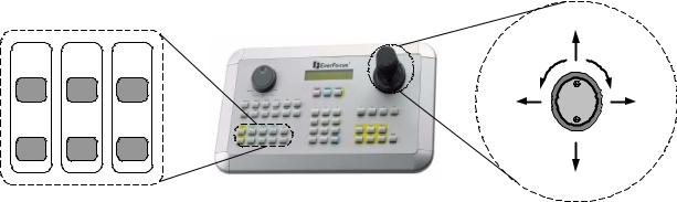
To operate the EPTZ3000/EPTZ3000I:
|
|
|
|
UP |
IRIS |
Focus |
Zoom |
Zoom OUT |
Zoom IN |
+ |
F. |
In |
|
|
|
|
LEFT |
|
RIGHT |
- |
N. |
Out |
|
|
|
|
|
|
DOWN |
1.Shift the Joystick up/down or right/left to view from camera.
2.Turn the top of the Joystick to zoom in/out.
3.Press Zoom In/Out, Focus F. /N. and IRIS +/- function keys to operate the
EPTZ3000/EPTZ3000I.
1-11
2. EPTZ3000/EPTZ3000I INSTALLATION
2.1. Packing List
There are 3 boxes that are housing, bulb and mechanical part with a camera module, one wall mount bracket, one power adapter and one tool packet in the package. The detail accessories list below:
Housing x1
Bulb x1
Mechanical part with a camera module x1
Wall mount bracket x1
Adapter x1
Tool packet
Glove x2
M5 Hex Allen wrench x1
Pin connector x1
M5 screw (Hex) x3 for wall mount bracket fixing
M3 screw x3 for bulb fixing
2.2.Cable Needed
Power Cable
An adapter with 24V AC/3.5A output provides the power to the EPTZ3000/EPTZ3000I. An extension power line may be needed.
Note: The input AC voltage range of an adapter depends on different area. Please make sure the voltage range before installing.
2-12
 Loading...