

Page 1

P-03
Super Audio CD Transport
Owner’s Manual
Page 2
2
CAUTION
<
DO NOT REMOVE THE EXTERNAL CASES OR CABINETS TO
EXPOSE THE ELECTRONICS. NO USER SERVICEABLE PARTS
ARE WITHIN!
<
IF YOU ARE EXPERIENCING PROBLEMS WITH THIS PRODUCT,
CONTACT TEAC FOR A SERVICE REFERRAL. DO NOT USE THE
PRODUCT UNTIL IT HAS BEEN REPAIRED.
<
USE OF CONTROLS OR ADJUSTMENTS OR PERFORMANCE OF
PROCEDURES OTHER THAN THOSE SPECIFIED HEREIN MAY
RESULT IN HAZARDOUS RADIATION EXPOSURE.
IMPORTANT SAFETY INSTRUCTIONS
1) Read these instructions.
2) Keep these instructions.
3) Heed all warnings.
4) Follow all instructions.
5) Do not use this apparatus near water.
6) Clean only with dry cloth.
7) Do not block any ventilation openings. Install in accordance with
the manufacturer’s instructions.
8) Do not install near any heat sources such as radiators, heat
registers, stoves, or other apparatus (including amplifiers) that
produce heat.
9) Do not defeat the safety purpose of the polarized or groundingtype plug. A polarized plug has two blades with one wider than
the other. A grounding type plug has two blades and a third
grounding prong. The wide blade or the third prong are provided
for your safety. If the provided plug does not fit into your outlet,
consult an electrician for replacement of the obsolete outlet.
10) Protect the power cord from being walked on or pinched
particularly at plugs, convenience receptacles, and the point
where they exit from the apparatus.
11) Only use attachments/accessories specified by the manufacturer.
12)Use only with the cart, stand, tripod,
bracket, or table specified by the
manufacturer, or sold with the apparatus.
When a cart is used, use caution when
moving the cart/apparatus combination to
avoid injury from tip-over.
13) Unplug this apparatus during lightning storms or when unused
for long periods of time.
14) Refer all servicing to qualified service personnel. Servicing is
required when the apparatus has been damaged in any way,
such as power-supply cord or plug is damaged, liquid has been
spilled or objects have fallen into the apparatus, the apparatus
has been exposed to rain or moisture, does not operate normally,
or has been dropped.
<
Do not expose this apparatus to drips or splashes.
< Do not place any objects filled with liquids, such as vases, on the
apparatus.
<
Do not install this apparatus in a confined space such as a book
case or similar unit.
<
The apparatus draws nominal non-operating power from the AC
outlet with its POWER switch in the off position.
<
The apparatus should be located close enough to the AC outlet
so that you can easily grasp the power cord plug at any time.
<
An apparatus with Class !construction shall be connected to an
AC outlet with a protective grounding connection.
CAUTION: TO REDUCE THE RISK OF ELECTRIC SHOCK,
DO NOT REMOVE COVER (OR BACK). NO USERSERVICEABLE PARTS INSIDE. REFER SERVICING TO
QUALIFIED SERVICE PERSONNEL.
The lightning flash with arrowhead symbol, within an
equilateral triangle, is intended to alert the user to the
presence of uninsulated “dangerous voltage” within the
product’s enclosure that may be of sufficient magnitude
to constitute a risk of electric shock to persons.
The exclamation point within an equilateral triangle is
intended to alert the user to the presence of important
operating and maintenance (servicing) instructions in the
literature accompanying the appliance.
WARNING: TO PREVENT FIRE OR SHOCK
HAZARD, DO NOT EXPOSE THIS APPLIANCE
TO RAIN OR MOISTURE.
This equipment has been tested and found to comply with the
limits for a Class B digital device, pursuant to Part 15 of the
FCC Rules. These limits are designed to provide reasonable
protection against harmful interference in a residential
installation. This equipment generates, uses, and can radiate
radio frequency energy and, if not installed and used in
accordance with the instructions, may cause harmful
interference to radio communications. However, there is no
guarantee that interference will not occur in a particular
installation. If this equipment does cause harmful interference
to radio or television reception, which can be determined by
turning the equipment off and on, the user is encouraged to
try to correct the interference by one or more of the following
measures:
• Reorient or relocate the equipment and/or the receiving
antenna.
• Increase the separation between the equipment and
receiver.
• Connect the equipment into an outlet on a circuit different
from that to which the receiver is connected.
• Consult the dealer or an experienced radio/TV technician
for help.
CAUTION
Changes or modifications to this equipments not expressly
approved by TEAC CORPORATION for compliance will void the
user’s warranty.
For U.S.A.
Page 3
3
Optical pickup :
Type : GH20707A2A
Manufacturer : SHARP CORPORATION
Laser output : Less than 1mW on the objective lens
Wavelength : 788±5 nm (CD)
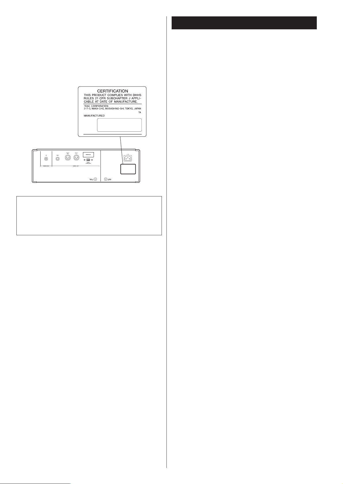
This product has been designed and manufactured according to
FDA regulations “title 21, CFR, chapter 1, subchapter J, based on
the Radiation Control for Health and Safety Act of 1968“, and is
classified as class 1 laser product. There is not hazardous invisible
laser radiation during operation because invisible laser radiation
emitted inside of this product is completely confined in the
protective housings.
The label required in this regulation is shown
①.
For U.S.A.
①
Contents
Thank you for choosing Esoteric. Read this manual
carefully to get the best performance from this unit.
VARING: APPARATEN INNEHÅLLER LASER KOMPONENT MED
STRÅLNING ÖVERSTIGANDE KLASS 1.
“ADVARSEL: USYNLIG LASERSTRÅLING VED ÅBNING NAR
SIKKERHEDSAFBRYDERE ER UDE AF FUNKTION. UNDGÅ
UDSAETTELSE FOR STRÅLING”
“VAROITUS! SUOJAKOTELOA EI SAA AVATA. LAITE SISÄLTÄÄ
LASERDIODIN. JOKA LÄHETTÄ (NÄKYMÄTÖNTÄ) SILMILLE
VAARALLISTA LASERSÄTEILYÄ”.
ADVARSEL: USYNLIG LASERBESTRÅLING NÅR DENNE DELEN ER
ÅPEN OG SIKKERHETSSPERREN ER UTKOBLET UNNGÅ
UTSETTELSE FOR STRÅLING.
Features . . . . . . . . . . . . . . . . . . . . . . . . . . . . . . . . . . . . . . . . . . 4
Before Use . . . . . . . . . . . . . . . . . . . . . . . . . . . . . . . . . . . . . . . . 6
Discs. . . . . . . . . . . . . . . . . . . . . . . . . . . . . . . . . . . . . . . . . . . . . 7
Connections . . . . . . . . . . . . . . . . . . . . . . . . . . . . . . . . . . . . . . . 8
Connection examples (connecting three D-03) . . . . . . . . . . . . 10
i.LINK (IEEE 1394) . . . . . . . . . . . . . . . . . . . . . . . . . . . . . . . . . . 11
Front panel features . . . . . . . . . . . . . . . . . . . . . . . . . . . . . . . . 12
Understanding the remote control unit . . . . . . . . . . . . . . . . . . 14
Remote Control Unit. . . . . . . . . . . . . . . . . . . . . . . . . . . . . . . . 15
Using the P-03 for the first time . . . . . . . . . . . . . . . . . . . . . . . 16
Digital output and selecting priority playback area . . . . . . . . . 17
Playback . . . . . . . . . . . . . . . . . . . . . . . . . . . . . . . . . . . . . . . . . 18
Selecting a track . . . . . . . . . . . . . . . . . . . . . . . . . . . . . . . . . . . 20
2ch/Multi ch . . . . . . . . . . . . . . . . . . . . . . . . . . . . . . . . . . . . . . 21
Programmed playback . . . . . . . . . . . . . . . . . . . . . . . . . . . . . . 22
Changing display mode . . . . . . . . . . . . . . . . . . . . . . . . . . . . . 23
Repeat mode . . . . . . . . . . . . . . . . . . . . . . . . . . . . . . . . . . . . . 23
Word sync . . . . . . . . . . . . . . . . . . . . . . . . . . . . . . . . . . . . . . . 24
Display dimming . . . . . . . . . . . . . . . . . . . . . . . . . . . . . . . . . . . 24
Up convert . . . . . . . . . . . . . . . . . . . . . . . . . . . . . . . . . . . . . . . 25
Settings (introduction). . . . . . . . . . . . . . . . . . . . . . . . . . . . . . . 26
Settings (Speaker). . . . . . . . . . . . . . . . . . . . . . . . . . . . . . . . 28
Settings (Audio) . . . . . . . . . . . . . . . . . . . . . . . . . . . . . . . . . 28
Troubleshooting . . . . . . . . . . . . . . . . . . . . . . . . . . . . . . . . . . . 30
Specifications . . . . . . . . . . . . . . . . . . . . . . . . . . . . . . . . . . . . . 31
Block Diagram . . . . . . . . . . . . . . . . . . . . . . . . . . . . . . . . . . . . 32
Page 4

4
The latest VRDS mechanism for Super Audio CD
(Specially developed ball bearings for the optimum VRDS mechanism.)
The VRDS mechanism securely clamps the disc to the turntable whose diameter is exactly the same
as that of the disc. This system completely eliminates vibration inherent to removable media and
unwanted vibrations generated by the mechanical systems. Also, this mechanism clamps the disc at
a slight inclination so as to compensate for warping or deformation improving the accuracy of the
optical axes of both the laser pickup and the pit surface of the disc. This is effective in reducing
errors in reading the disc data as well as in preventing timing errors from erratic data acquisition
timing.
To achieve the high-speed rotation with superior stability that is required of a Super Audio CD
player, the P-03 is equipped with a duralumin turntable. A specially developed processing
technology was used to enable high-precision forming of this lightweight material normally used in
building aircraft.
In a joint development project with NSK Ltd., we developed proprietary, highly precise ball bearings
for the VRDS mechanism. Rolling elements made from precisely machined ceramic balls provide
ultra smooth rotation. The application of a pre-load to the ball bearing pair ensures a high rigidity
and precise rotation not present in conventional bearings but necessary for handling the wide
rotational range from normal CD to Super Audio CD playback.
A massive 20mm-thick, SS400 steel bridge supports the mechanism to control vibrations produced
by turntable rotation.
Coreless motor employing neodymium magnet
Esoteric has developed a new, life-long three-phase brushless spindle motor for high-speed rotation
of the large diameter turntable. Combined with the high-precision ball bearings that firmly hold the
turntable in place, this motor helps to further minimize rotation irregularities and vibrations. The
magnetic field of the neodymium magnet has been optimized through magnetic field analysis to
minimize fluctuations in motor drive current and reduce the impact on audio circuits.
A pickup designed to prevent tilting of the laser optical axis and
speed feedback-controlled sled transport
The pickup of the P-03 has a highly rigid sliding-shaft structure that prevents the lens from tilting
and the laser optical axis is kept precisely aligned with the media’s bit track. The sled moving
mechanism uses a proprietary Hall element sensing-type, three-phase brushless motor while
powerful electronic speed feedback circuits control this sled mechanism for quick access, thereby
ensuring smooth, continuous movement with superior response.
Shutter isolates the mechanism from external influences
The tray opening and closing mechanism is equipped with a shutter for greater precision and to
eliminate adverse effects from external sound pressure and vibrations on mechanical units. When
closed, the shutter mechanism is mechanically secured to the front panel to prevent it from
moving.
Power supply housed in separate chassis
The P-03 shares the dual block structure concept introduced in the P-01 where the power supply
and the VRDS mechanism are housed in independent blocks.
The enclosure provides a high degree of isolation yet high capacity in a compact design.
The power supply consists of two transformers, one for the mechanism and the servo drive and the
other for processing digital signals. The WB transformer for the mechanism and the servo drive
ensures low current loss and quick response.
Features
Page 5

5
Highly rigid chassis completely eliminates internal and external
vibrations preventing sound quality deterioration
The bottom plate of the chassis that supports the mechanisms is 5 mm thick and weighs 6 kg.
Thick aluminum is used in the top, side, bottom and front panels. Esoteric-exclusive pinpoint feet
(patent pending) made of quenched steel support the chassis. Every possible effort has been
accorded to precision in the mounting of mechanical parts, the rigidity of the housing and
eliminating sympathetic vibration. The thick, brushed-aluminum front, top, bottom and side panels
contribute to a sense of quality and elegance found only in high-end Super Audio CD/CD units.
Upward conversion on CD playback
The upward conversion feature can output a maximum fs 176.4 kHz when playing back CDs. A
high-precision crystal oscillator precise to ±3ppm (temperature characteristics included) minimizes
jitter. During Super Audio CD playback, the DSD signal (1-bit, 64 fs) is output directly without
further processing. A mode for converting the CD PCM signal to DSD has also been added. This
gives the P-03 accurate control over signal differences for optimal expression of tonal texture
required by each signal type. It is thus possible to select the audio format (PCM or DSD) that best
suits the music genre played back or the amplifier and speaker combinations used to provide a
musical experience that only Esoteric is capable of.
Digital audio output
The output terminals include two XLR jacks (in ES-LINK and Dual AES output modes, both jacks are
used), one RCA jack and one i.LINK jack. The RCA jacks do not output sound from Super Audio
CDs.
ES-LINK, an Esoteric-exclusive format for Super Audio CD digital
output
Super Audio CD output is output in the Esoteric-exclusive ES-LINK format from the XLR jacks or the
i.LINK (AUDIO) jacks. When a Super Audio CD is played back and XLR DUAL is selected, the output
is automatically output in the ES-LINK format. Currently, only the D-03 and D-01 Esoteric D/A
converters support ES-LINK.
WORD SYNC
The word sync feature allows this unit to synchronize with an external word clock. The input
frequency can be switched between 44.1, 88.2, 176.4 and 100 kHz. The P-03 is designed so that
the phase shift between the word clock and output sampling frequency is kept within 10 degrees
when there is no discrepancy between the two.
High-quality wires for maximum performance
High purity 6N copper wires are used for most internal wiring that affect sound quality to improve
purity and sound texture resolution. Polyolefin, a non-PVC material was used for the insulating
sheath out of consideration for the environment as well as for sound quality. PVC is not used for
wire insulation. The high purity 6N copper cable is developed with the help of Acro Japan Ltd. who
also developed the highly acclaimed Esoteric MEXCEL interconnection cable and high-purity 8N
copper cable.
Play Area button on front panel
The front panel now has a PLAY AREA button to enable selection of play area for hybrid Super
Audio CDs also on the front panel.
Page 6
6
What’s in the box
Please confirm that the following accessories are in the box
when you open it.
Power cord x 1
Screwdriver x 1
Remote control unit x 1
Batteries (AA, R6 or SUM-3) x 2
Felt pad x 3
Owner’s manual x 1
Warranty card x 1
Conventions about This Manual
< The types of functions and operations that can be used for a
particular disc vary depending on the features built into that
disc. In some cases, these functions and operations may differ
from the descriptions given in this Owner’s Manual.
<
The drawings about the front panel display used in this
Owner’s Manual are purely for the purposes of explanation.
The actual displays may differ slightly from what are shown
here.
Read this before operation
< As the unit may become warm during operation, always leave
sufficient space around the unit for ventilation.
<
The voltage supplied to the unit should match the voltage as
printed on the rear panel. If you are in any doubt regarding
this matter, consult an electrician.
<
Choose the installation location of your unit carefully. Avoid
placing it in direct sunlight or close to a source of heat. Also
avoid locations subject to vibrations and excessive dust, heat,
cold or moisture.
<
Do not place the unit on the amplifier/receiver.
<
Do not open the cabinet as this might result in damage to the
circuitry or electrical shock. If a foreign object should get into
the unit, contact your dealer or service company.
<
When removing the power plug from the wall outlet, always
pull directly on the plug, never yank the cord.
<
To keep the laser pickup clean, do not touch it, and always
close the disc tray.
<
Do not attempt to clean the unit with chemical solvents as
this might damage the finish. Use a clean, dry cloth.
<
Keep this manual in a safe place for future reference.
DO NOT MOVE THE UNIT DURING PLAYBACK
During playback, the disc rotates at high speed. Do NOT lift or
move the unit during playback. Doing so may damage the
disc or the unit.
WHEN MOVING THIS UNIT
When changing places of installation or packing the unit for
moving, be sure to remove the disc and return the disc tray to
its closed position in the player. Then, press the power switch
to turn the power off, and disconnect the power cord.
Moving this unit with the disc loaded may result in damage to
this unit.
Before Use
Placement of the unit
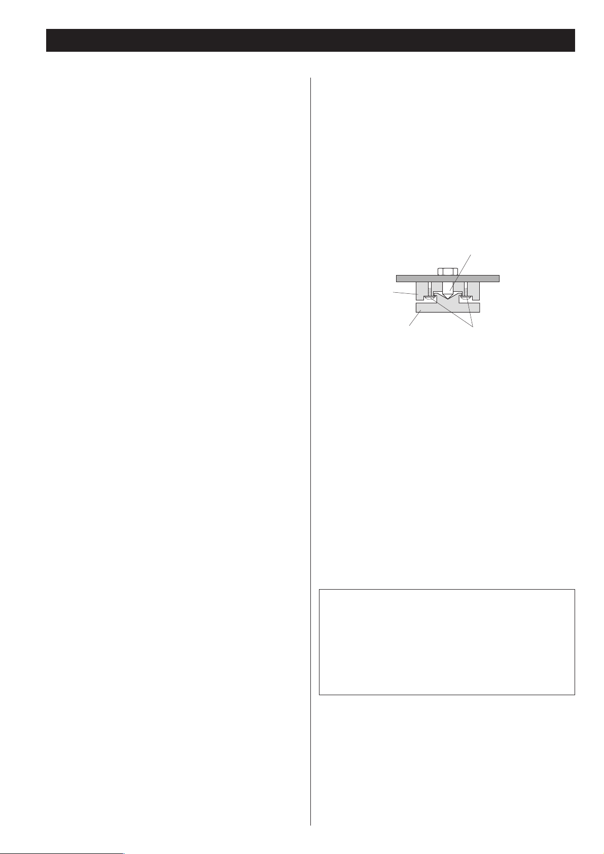
High-quality hardened tool steel is used for the pin-point feet
attached to the bottom of the player. Although the outer feet
may appear loose, the weight of the unit causes them to
become firm and secure. The design effectively damps and
reduces vibration.
<
WARNING: Be careful to avoid injury when moving the unit.
This unit weighs about 30 kg. Seek assistance when moving
or placing this product.
<
To protect the supporting furniture surface, you may stick the
felt pads supplied with the unit to the bottom of the metal
feet.
Pin-point foot
Bottom plate
of the unit
Steel foot
Cover foot retaining screws
Cover foot
Beware of condensation
When the unit (or a disc) is moved from a cold to a warm
place, or used after a sudden temperature change, there is a
danger of condensation; vapor in the air could condense on
the internal mechanism, making correct operation impossible.
To prevent this, or if this occurs, leave the unit for one or two
hours with the power turned on. Then the unit will stabilize at
the temperature of its surroundings.
Maintenance
If the surface of the unit gets dirty, wipe with a soft cloth or
use diluted neutral cleaning liquid. Be sure to remove any
fluid completely. Do not use thinner, benzine or alcohol as
they may damage the surface of the unit.
Frame
CAUTION
Ensure this product is not exposed to dripping or splashing
and that no object filled with liquids, such as vases, is placed
on the product.
Do not install this equipment in a confined space such as a
book case or similar unit. Allow adequate air circulation
around this product.
“Super Audio CD” is a registered trademark.
“DSD” is a registered trademark.
The i.LINK logo is a trademark of Sony Corporation, registered in
the U.S. and other countries.
Page 7
7
Discs
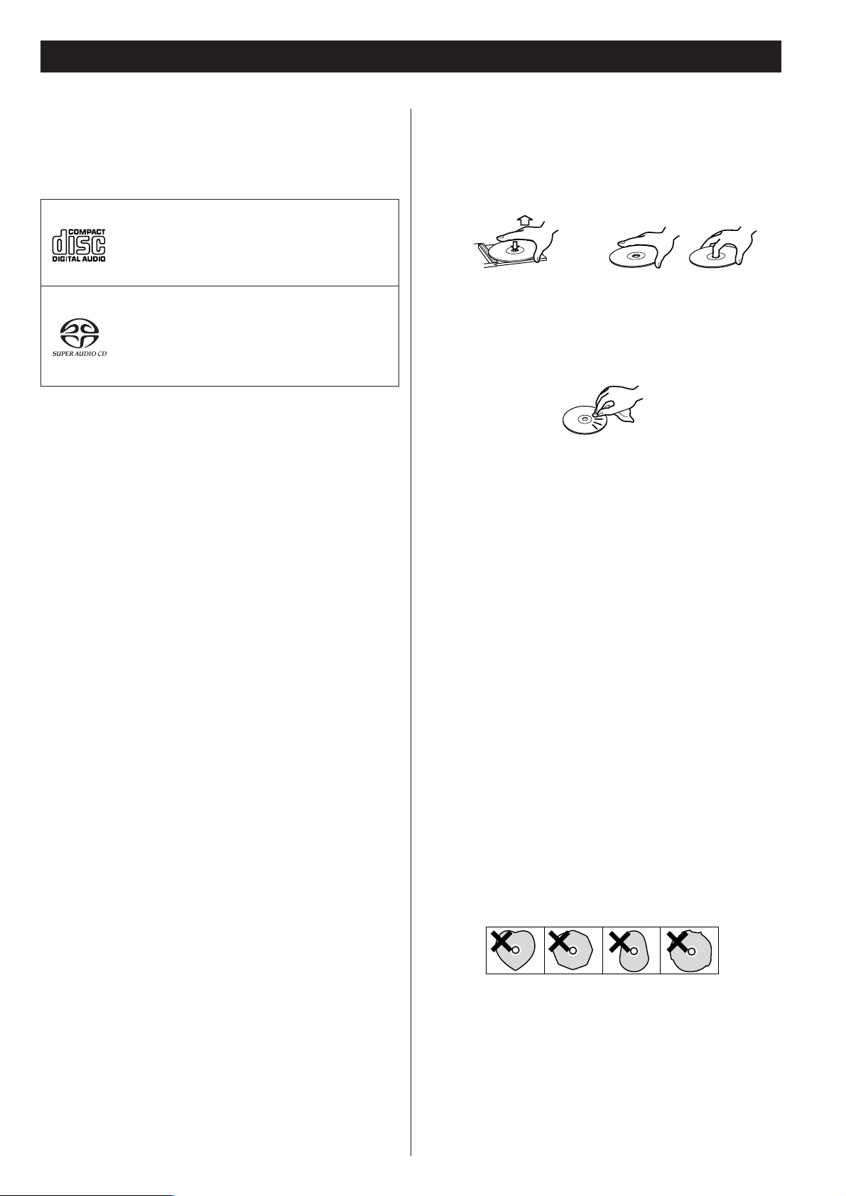
Audio CD:
• 12cm or 8cm discs
• Linear PCM digital audio
Audio CDs are divided into tracks.
Super Audio CD:
• Single layer, dual layer or Hybrid layer
• 12cm or 8cm discs
• Digital audio (DSD)
Super Audio CDs are divided into tracks.
Type of discs that can be played on this
system
This player can playback discs bearing any of the following logos:
About CD-R/CD-RW
CD-R/RW discs recorded in Audio CD format and finalized
correctly are playable. But depending on the quality of the
disc and/or the condition of the recording, some CD-R & CDRW discs may not be playable.
Caution:
<
If you record a disc using a personal computer, even if it is
recorded in a compatible format, there are cases in which it
may not play because of the settings of the application
software used to create the disc. (Check with the software
publisher for more detailed information.)
<
Unfinalized CD-R/CD-RW discs cannot be played.
Following discs cannot be played with this
unit:
• DVD, CD-G, Data part of CD-EXTRA, PHOTO CD, CD-ROM
and DVD-ROM discs
• illegally produced discs
• scratched or damaged discs
• discs that are dusty, soiled or marked with fingerprints
• DualDisc
Warning:
If you attempt to play back such discs, there is a risk that sudden
loud noise can blast over the speakers at full volume and cause
damage to the speakers and your hearing.
Copy-protected discs and other discs that do not conform to the
CD standard may not play back correctly in this player. If you use
such discs in this unit, TEAC ESOTERIC COMPANY cannot be
responsible for any consequences or guarantee the quality of
reproduction. If you experience problems with such nonstandard discs, you should contact the producers of the disc.
How to remove the disc How to hold the disc
< Always place the disc on the disc tray with the label side up.
(Compact discs can be played or recorded only on one side.)
<
To remove a disc from its storage case, press down on the
center of the case and lift the disc out, holding it carefully by
the edges.
<
Should the disc become dirty, wipe the surface radially (from
the center hole outward towards the outer edge) with a soft,
dry cloth:
<
Never use such chemicals as record sprays, antistatic sprays or
fluid, benzine or thinner to clean the discs. Such chemicals
will do irreparable damage to the disc’s plastic surface.
<
Discs should be returned to their cases after use to avoid dust
and scratches that could cause the laser pickup to “skip.”
<
Do not expose discs to direct sunlight or high humidity and
temperature for extended periods. Long exposure to high
temperatures will warp the disc.
<
Do not play any disc that is warped, deformed or damaged.
Playing such discs may cause irreparable harm to the playing
mechanisms.
<
CD-R and CD-RW discs are more sensitive to the effects of
heat and ultraviolet rays than ordinary CDs. It is important
that they are not stored in a location where direct sunlight
will fall on them, and which is away from sources of heat
such as radiators or heat-generating electrical devices.
<
Printable CD-R and CD-RW discs aren’t recommended, as the
label side might be sticky and damage the unit.
<
Do not stick papers or protective sheets on the discs and do
not use any protective coating spray.
<
Use a soft oil-based felt-tipped pen to write the information
on the label side. Never use a ball-point or hard-tipped pen,
as this may cause damage to the recorded side.
<
Never use a stabilizer. Using commercially available CD
stabilizers with this unit will damage the mechanisms and
cause them to malfunction.
<
Do not use irregular shape CDs (octagonal, heart shaped,
business card size, etc.). CDs of this sort can damage the unit:
<
If you are in any doubt as to the care and handling of a CDR/CD-RW disc, read the precautions supplied with the disc, or
contact the disc manufacturer directly.
Page 8
8
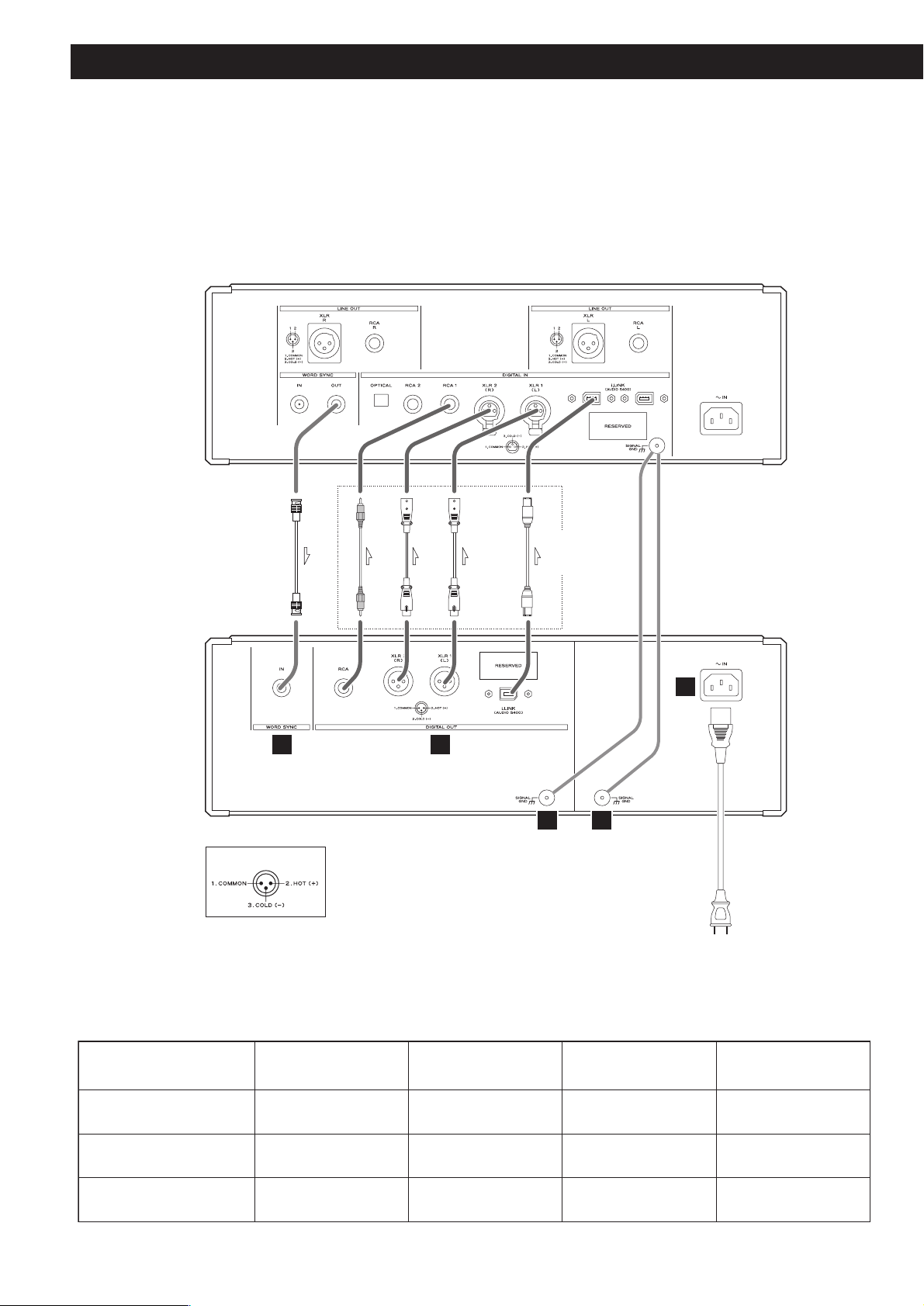
Connections
CAUTION:
<
Switch off the power to all equipment before making connections.
<
Read the instructions of each component you intend to use with this unit.
<
Be sure to insert each plug securely. To prevent hum and noise, avoid bundling the
signal interconnection cables together with the AC power cord or speaker cables.
BNC coaxial digital cable
XLR digital cable
RCA coaxial cable
XLR digital cable
i.LINK cable
XLR pin assignment
Connect one of
these cables.
Wall outlet
D/A converter (D-03)
AB
P-03
Digital signal output by each terminal
Both XLR terminals
connected to an
ES-LINK device
Super Audio CD playback
Single XLR connection
No
Yes
C D
i.LINK connection RCA connection
Yes
E
No
Upconversion to CONV 44.1,
88.2, 176.4 during CD playback
Upconversion to CONV DSD
during CD playback
Up to 176.4 kHz
No
Up to 176.4 kHz
Yes
(44.1 kHz*)
(44.1 kHz*)
Up to 176.4 kHz
No
*: Signals output by the i.LINK terminal do not go through the upconverter circuit and are not upconverted.
Page 9

9
Digital audio output terminals
These terminals output digital audio. Connect these terminals to the corresponding terminals on
the D/A converter (D-03, etc.).
Use commercially available cables for the following connections.
XLR: Use a balanced XLR digital audio cable
RCA: Use an RCA coaxial digital cable
i.LINK (Audio S400): Use S400 compatible 6-pin i.LINK cable (IEEE 1394 cable)
Select digital output depending on what terminals are connected (see pages 16-17).
Output of digital audio from a Super Audio CD requires a D/A converter compliant with
Esoteric ES-LINK (D-03/D-01) or a D/A converter with an i.LINK (AUDIO) terminal.
<
If your D/A converter supports ES-LINK or Dual AES, connect the XLR1 (L) terminal on this unit to
the left XLR terminal of the D/A converter and the XLR2 (R) terminal on this unit to the right XLR
terminal of the D/A converter.
<
The i.LINK (AUDIO) terminal is a combined input and output cable interface.
<
When using an i.LINK terminal, select i.LINK output setting (Stream Out) as required by connected
devices (see pages 26-28).
< RESERVED indicates area allocated for future expansion of P-03 terminals.
Word sync input terminal (WORD SYNC IN)
This terminal allows the use of an externally generated word clock connection using a
commercially available BNC coaxial cable (75 ohm).
Connect the WORD SYNC OUT terminal on a D/A converter or word clock generator to this unit.
Signal GND terminal
Power supply GND terminal
Connecting the ground terminals on the D/A converter and amplifiers to ground may improve the
sound quality.
< Note that this is not an electrical safety ground (earth).
Power cord
Connect the power cord to the power cord receptacle and connect the power plug to a AC wall
outlet when all other connections have been made.
<
Although the power cord receptacle has a 3-pin plug, the ground pin is not connected to the
chassis.
<
Use only the supplied Esoteric power cord. Use of other power cords may result in fire or electric
shock. Unplug the power cord when you are not going to use the unit for some time.
E
D
C
B
A
Page 10
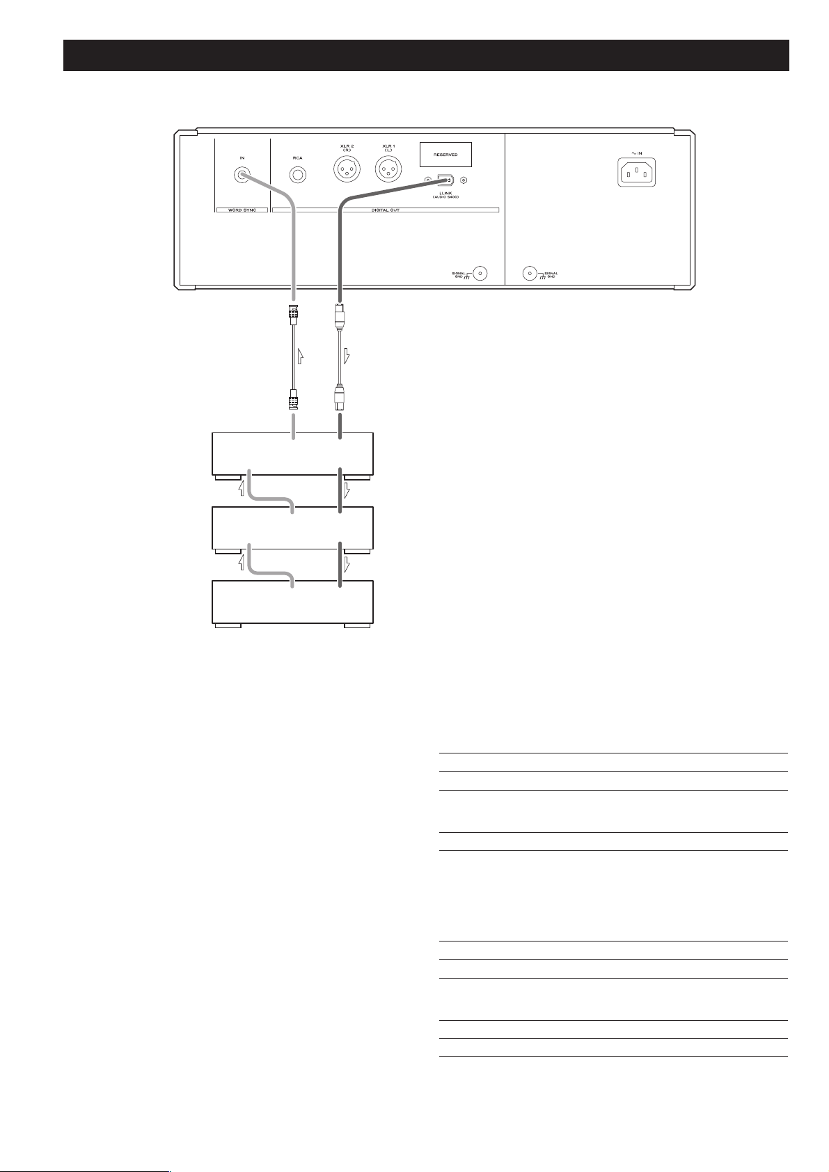
10
Connection examples (connecting three D-03)
Three D-03 units are required to play multi-channel sound
from a Super Audio CD without mixing it down to stereo.
First, connect the i.LINK (AUDIO) terminal on the P-03 to
the D-03 i.LINK (AUDIO) terminal. Then connect the other
i.LINK (AUDIO) terminal on the D-03 to the next D-03 unit.
Daisy chain the three units similarly (in random order).
Connect the word sync terminals as shown in the figure (in
random order).
When connecting clock generator G-0/G-0s to the P-03, connect
the WORD CLOCK OUT terminals to the WORD SYNC IN on the
P-03.
Setting of the P-03
Digital Output setting i.LINK (see pages 16-17)
WORD button
ON
Setting of the D-03
INPUT button i.LINK
WORD button One of the D-03 that outputs word
synchronization signals: “OUT”
The others: “IN”
When the G-0 is connected, set all
the D-03s to “IN”.
W_OUT setting 176.4 or 88.2
CH_SEL setting respective channels
Setting of the G-0/G-0s
Frequency change button (A, B or C) 176.4 kHz or 88.2 kHz
FREQUENCY MODE button 44.1kHz
BNC coaxial digital cable
i.LINK cable
D-03
(LS/RS)
D-03
(C/LFE)
D-03
(L/R)
WORD
WORD
SYNC
IN
SYNC
IN
WORD
SYNC
OUT
WORD
SYNC
OUT
WORD
SYNC
OUT
i.LINK(AUDIO)
i.LINK(AUDIO)
i.LINK(AUDIO)
i.LINK(AUDIO)
i.LINK(AUDIO)
Page 11

11
i.LINK (IEEE 1394)
The i.LINK is also known as IEEE 1394, an international
specification.
This unit is ready for i.LINK (AUDIO).
By connecting an i.LINK (AUDIO)-capable device to the IEEE 1394
(or i.LINK (AUDIO) terminal on this unit using an i.LINK cable, you
can transmit Super Audio CD multi-channel signals that could
not be transmitted but in analog format in the past can be
transmitted in its original digital format, in addition to the
capability of transmitting 2-ch linear PCM data and multichannel compressed audio signals.
If you have multiple i.LINK-capable devices, you can connect
them through other devices to transmit data between them, so
you don’t need to be concerned with the order of connection.
Copyright protection system DTCP
To play back audio sounds recorded on Super Audio CD or DVD
discs using i.LINK, both the player and the D/A converter need to
be ready for the copyright protection system DTCP (Digital
Transmission Content Protection).
This unit is ready for DTCP.
Data transfer rate
There are three transfer rates: 100 Mbps (S100), 200 Mbps
(S200), and 400 Mbps (S400). This unit is capable of transferring
data at a maximum 400Mbps.
For connection to an i.LINK-capable device, use a commercially
available S400-compliant 6-pin i.LINK cable.
When connecting multiple i.LINK-capable devices, avoid
connecting a device having slow transfer rate between devices
having high transfer rate since this reduces the transfer rate of
your whole system. Connect devices having high transfer rate
towards the source as far upriver as possible.
NOTES
<
Among the i.LINK formats there are “MPEG-2 TS” for BS
digital source and “DV” for digital video for DVD recorders,
as well as the “i.LINK (AUDIO)” (A&M Protocol). Never
connect devices that are not ready for i.LINK (AUDIO) to this
unit. If you do, this unit and others may get out of order or be
damaged.
<
In the process of data transfer, avoid plugging/unplugging the
i.LINK cables in use or switch on/off the power.
< Among the i.LINK-capable devices there are some that, if not
turned on, are not capable of relaying data.
< Chances are some i.LINK-capable devices will not respond to
this unit's command.
< The receiving device may not support the output modes of
this unit. Read through the instruction manual of devices you
wish to connect before making connections.
How to connect multiple i.LINK-capable
devices
Daisy chain connection
You can daisy-chain up to 17 devices including this unit.
Connection in tree structure
If you are using a device having three or more i.LINK connectors,
you may want to get the connection branched out. This way of
connection allows you to connect up to 17 devices including this
unit.
Your system does not work if data is fed back to the output
device. Be careful not to create a loop.
i.LINK-capable
device
i.LINK-capable
device
i.LINK-capable
device
i.LINK-capable
device
i.LINK-capable
device
i.LINK-capable
device
i.LINK-capable
device
i.LINK-capable
device
i.LINK-capable
device
i.LINK-capable
device
i.LINK-capable
device
i.LINK-capable
device
i.LINK cable
i.LINK-capable
device
i.LINK-capable
device
i.LINK-capable
device
The i.LINK interface of this unit is designed in accordance with
the following specifications:
1)IEEE Std 1394a-2000, Standard for a High Performance
Serial Bus
2) Audio and Music Data Transmission Protocol 2.0
This unit is compliant with IEC 60958 bitstream, DVD-Audio,
Super Audio CD in the AM824 sequence adaptation layers of
this protocol.
Page 12

12
Front panel features
POWER
Turn power on and off. The ring surrounding the button lights when the unit is on.
PLAY AREA
When a hybrid Super Audio CD is loaded and the disc is not being played, press this
button to change the play area of the disc.
Hold down this button for 2 seconds or more to engage digital output and the
priority playback area setup mode.
Disc tray and shutter
SKIP (.
//)
Use these buttons to skip forward or backward. Hold down the buttons 1 second or
more to change scanning speed.
OPEN/CLOSE
Press to open or close the disc tray.
The indicator flashes when the disc tray is being opened or closed and also when a
disc is being read.
The indicator lights when there is a disc in the tray.
PLAY
Press to play and press again to pause playback.
The indicator lights during playback and blinks when paused.
STOP
Press to stop playback.
Display
Remote control sensor
Receives signals from the remote control unit. Point the remote control at this sensor
when using the remote control.
UP CONVERT
Use this button to convert the sampling frequency.
WORD
Turn the word sync function on and off. When on, the unit will synchronize with an
external word sync source.
K
J
I
H
G
F
E
D
C
B
The equipment draws nominal non-operating power from the AC outlet with its
POWER switch in the OFF position.
A
BA C D E
J I H G FK
Page 13

13
Disc type indicator
Indicates the disc type of loaded disc (Super Audio CD or CD).
TRACK indicator
Indicates that the track number of a disc is being shown.
TOTAL indicator
Indicates that the total playback time is being shown.
REMAIN indicator
Indicates that the remaining playback time is being shown.
GUI indicator
Lights when the SETUP button is pressed and the setup mode is engaged.
DOWN MIX indicator
Lights to show that a multi-channel source has been downmixed.
5.1 CH indicator
Lights to show that a “Multi ch” has been selected.
Channel indicators
Light to show which surround channels are currently in use.
Message area
Alphanumeric display that shows playback time, status messages, etc.
REPEAT indicator
Lights when repeat play is selected.
Pause indicator
Lights when playback is paused.
Playback indicator
Lights during playback.
l
k
j
i
h
g
f
e
d
c
b
a
a
b
c
h
i
k
j
l
d
f
e
g
Front panel features (Display)
Page 14

14
Understanding the remote control unit
Number buttons
Enter the track number.
PLAY AREA
When a hybrid Super Audio CD is loaded and the disc is not
being played, press this button to change the play area of the
disc.
2CH/MULTI
Press to select 2-channel stereo or multi-channel surround
audio output.
SCAN
Press to scan forward and backward during playback.
STOP (H)
Press to stop playback.
PLAY (y)
Press to start playback.
Cursor buttons and ENTER
Use to navigate in the setup mode. Use the cursor buttons to
select an item and press ENTER to confirm made selection.
SETUP
Use to enter or exit the setup mode.
OPEN/CLOSE (L)
Press to open or close the disc tray.
CLEAR
Press to clear entry errors.
DISPLAY
Press to change display mode.
FL DIMMER
Press to select one of four brightness levels for the display and
indicator lamps.
REPEAT
Press to engage the repeat playback mode.
M
L
K
J
I
H
G
F
E
D
C
B
A
A
D
I
J
N
K
L
M
B
C
S
O
E
F
P
G
H
Q
R
Page 15

15
PROGRAM
Press to engage the program mode.
SKIP (.//)
Press to skip forward or backward during playback.
PAUSE
Press to pause playback.
RETURN
Press in the setup mode to return to a previous level in the
setup menu.
DAC OUTPUT LEVEL
Use to adjust the output level on the D/A converter D-01. Be
sure to point the remote control at the D-01 display when
using this function. (This function is not available on the D-
03.)
DVD audio operating buttons
The following buttons are used for controlling DVD-Audio
and will become available after a future upgrade.
AUDIO
Press to select audio playback during DVD-Audio playback.
GROUP
Press to skip groups during DVD-Audio playback.
S
R
Q
P
O
N
Battery Replacement
If the distance required between the remote control unit and
main unit decreases, the batteries are exhausted. In this case
replace the batteries with new ones.
Precautions concerning batteries
<
Be sure to insert the batteries with correct positive “+” and
negative “_
” polarities.
<
Use batteries of the same type. Never use different types of
batteries together.
<
Rechargeable or non-rechargeable batteries can be used but
not mixed together. Refer to the precautions on their labels.
<
When the remote control unit is not to be used for a long
time (more than a month), remove the batteries from the
remote control unit to prevent them from leaking. If they
leak, wipe away the liquid inside the battery compartment
and replace the batteries with new ones.
<
Do not heat or disassemble batteries and never dispose of old
batteries by throwing them in a fire.
Notes on use
<
Point the remote control unit at the main unit’s remote sensor
within seven meters (23 feet) of the main unit. There should
not be any obstacles between the player and the remote
control unit.
<
Do not allow direct sun or other light to shine on the remote
sensor part of the main unit. This may cause the remote
control unit to work incorrectly.
<
Note that other units with remote controls may operate
incorrectly because of infrared light “overspill” when you
operate this remote control unit.
How to insert the batteries
Remove the cover of the remote control unit with a
screwdriver. After checking the polarity (+
/_) of two AA
batteries, insert the batteries, replace the cover and replace
the screws.
Remote Control Unit
Page 16

16
Using the P-03 for the first time
When using the P-03 for the first time or after the P-03 has been
reset to factory defaults, it is necessary to setup the digital
outputs.
When all connections are completed, perform the following
operations. Note that no sound may be output unless the setup
required by the terminal connections are properly performed.
Turn the unit on.
1
Use the SKIP button (.//) to select digital output.
2
Press the PLAY AREA button twice to exit setup.
3
“OUT>Select” blinks on the display.
XLR, DUAL, i.LINK, RCA
The output changes with each press of the button. Select the
terminal to which the D/A converter is connected.
< Select DUAL when a dual AES device is connected to the unit
using XLR digital cables.
< ES-LINK is a proprietary Esoteric format enabling Super Audio
CD digital output. In order to output signals in ES-LINK
format, connect an Esoteric ES-LINK compliant D/A converter
(D-03 or D-01) to the two XLR terminals on the unit using XLR
digital cables, select the DUAL digital output, and play a
Super Audio CD.
If you want to change the setting, refer to the following
page.
Page 17

17
Digital output and selecting priority playback area
Select digital output according to connected terminals.
Note that incorrect selection will result in no sound
output.
Perform the operations described in the section “Using the P-03
for the first time” on the previous page before using the P-03 for
the first time or after the P-03 has been reset to factory defaults.
Turn the unit on.
1
Hold down the PLAY AREA button for 2 seconds or
more.
2
Release the button when “OUT>
***
” appears on the
display.
(“
***
” depends on the setting.)
The GUI indicator lights when the setup mode is engaged.
Use the SKIP button (.//) to select digital output.
3
The output changes with each press of the button. Select the
terminal to which the D/A converter is connected.
< Select DUAL when a dual AES device is connected to the unit
using XLR digital cables.
< ES-LINK is a proprietary Esoteric format enabling Super Audio
CD digital output. In order to output signals in ES-LINK
format, connect an Esoteric ES-LINK compliant D/A converter
(D-03 or D-01) to the two XLR terminals on the unit using XLR
digital cables, select the DUAL digital output, and play a
Super Audio CD.
To select a digital output, perform operations up to
Step . Then wait for 10 seconds until the display
returns to normal.
To select a Super Audio CD area, go to Step .
4
3
Gently press the PLAY AREA button.
4
“LAYER>SACD” or “LAYER>CD” appears on the display.
There are two types of Super Audio CDs, regular ones that
contain 2-channel stereo and multi-channel stereo and hybrid
discs (two-layer discs) that contain Super Audio CD and
regular CD data.
The setting described here allows you to determine which
layer will be first selected for playback (the priority playback
layer) with a hybrid Super Audio CD.
Press SKIP (.//) to change setting.
5
SACD (default setting):
This mode gives priority to the Super Audio CD layer. The
“2ch” setting of the “2ch/Multi ch” selection plays back the
2-channel layer while the “Multi ch” setting plays back the
multi-channel layer.
CD:
This mode gives priority to the CD layer.
<
Selecting a layer that is not on the disc results in playback of
the layer found on the disc.
<
A change of playback layer using the PLAY AREA button
when playback is stopped is overridden by the setting
selected using operations described here when a different
disc is loaded.
Gently press the PLAY AREA button (or leave the unit
idle for 10 seconds) to exit setup.
6
Page 18

18
Playback
Turn the unit on.
1
Each press of the POWER button turns the unit on and off.
The ring around the button and the display lights when the
unit is on.
<
Also turn on D/A converters, amplifiers and other devices
connected to the unit.
< When the WORD button is set to on, “WRD UNLOCK!” or
“NO WORD” will appear on the display when the unit is
turned on as a word signal cannot be detected as soon as the
unit is powered up. These messages vanish when the word
signal is locked.
Press the OPEN/CLOSE button.
2
The shutter opens and the disk tray slides out.
<
The tray opens after a few seconds (this delay is normal and
due to the movement of internal mechanisms in the unit
before opening).
Place the disc in the disc tray with the label side up.
3
Make sure the disc is placed in the center tray recess to avoid
malfunction or jamming of the tray.
Press the OPEN/CLOSE button.
4
The disc tray and shutter opens. Take care to avoid pinching
your fingers in the moving tray.
< The OPEN/CLOSE button indicator flashes when the tray
opens or closes and when a disc is being read.
< The unit reads the disk, which takes some time. “LOADING”
appears on the display during reading. After reading, the total
number of tracks on the disc and total playback time appears.
Press the PLAY/PAUSE button.
Playback starts.
5
1 5
2 43
Page 19

19
Pausing playback
Press the PLAY/PAUSE button to momentarily pause playback.
The indicator lights when playback is paused.
Press the PLAY/PAUSE button again to resume playback.
Stopping playback
Press the STOP button.
Opening and closing the disc tray
Press the OPEN/CLOSE button once to open (or close) the tray
and press it a second time to close (or open) the tray.
< It takes longer time for the tray to open when the
OPEN/CLOSE button is pressed during playback.
Selecting playback area
There are two types of Super Audio CDs, regular ones that
contain 2-channel stereo and multi-channel stereo and hybrid
discs (two-layer discs) that contain Super Audio CD and
regular CD data.
Use the PLAY AREA button to select a playback area on a
hybrid Super Audio CD when such a disc is loaded but not in
playback mode.
<
The setting described on page 17 allows you to determine
which layer will be first selected for playback (the priority
playback layer).
Page 20

20
Selecting a track using the number buttons
Use the number button to select tracks for playback. Use the
+10 button to enter the first digit of numbers greater than 9
(repeated presses will show 1-, 2-, 3- etc.) and the single digit
buttons (0 through 9) for the second digit, or single-digit
track numbers.
Playback starts from the selected track, regardless of whether
the number is selected during playback or when playback is
stopped or paused.
Skipping playback
Press the SKIP button on the front panel or the remote
control (.
//) during playback to skip to the next or
previous track.
< Press the . button once to return to the beginning of the
current track. Further presses of the .
button will take you
further back.
Note that pressing the .
button when 1 second or less of
the current track has been played will move playback to the
previous track.
<
Pressing the .// button when playback is paused or
stopped, pauses or stops playback at the beginning of the
selected track.
Selecting a track
Page 21

21
Page 22

22
Programmed playback
Programmed playback allows up to 30 tracks to be played back
in the order you decide.
Press the PROGRAM button either during playback or
when playback is stopped.
The currently played track is added as the first item in the
programmed playback list.
1
Use the number buttons to add tracks to the
programmed playback list.
Use the +10 button and 0 through 9 buttons in exactly the
same way as when selecting tracks.
2
The total time of programmed tracks is displayed,
then the program number (1 to 30) appears.
Programmed track number
Continue pressing the number buttons to add tracks.
<
Clear mistakes with the CLEAR button (the last entry is
cleared)
<
You can only select tracks on the disc (in other words, if the
disc has six tracks, you cannot program track 7).
Press the PLAY (y) button when a program entry is
completed.
Programmed playback starts.
<
The PLAY button need not be pressed when programs are
made during playback.
3
Editing programs
Press the CLEAR button to delete the last added track
number.
Adding programs
Use the number buttons to add track numbers during
playback or when playback is stopped.
Returning to normal playback
Press the PROGRAM button to exit the program mode.
Note that pressing the PROGRAM button during
programmed playback cancels the programmed playback
and normal playback is resumed.
<
The content of the program is canceled.
Pressing the OPEN/CLOSE button will also clear program
data.
Page 23

23
Repeat mode
Use the REPEAT button to select the repeat mode for
playback. Repeated presses of the REPEAT button cycle
between the following options.
<
Halting playback stops the repeat mode.
<
The following buttons cancel repeat mode:
STOP, OPEN/CLOSE, POWER.
REPEAT TRK (Track repeat)
Repeats the currently selected track. When another track is
selected during repeat playback, this track repeats.
REPEAT DSC (Disc repeat)
Repeats all the tracks on the disc.
Press the REPEAT button once to repeat playback of the
programmed tracks.
Programmed repeat
If programmed playback has been set up, the whole program
is repeated.
Pushing the REPEAT button cycles between REPEAT PGM
(program repeat) and REPEAT OFF (programmed playback
takes place).
REPEAT TRK
(repeat the track)
REPEAT DSC
(repeat the whole disc)
REPEAT OFF
(no repeat)
Elapsed time of current trackCurrently playing track
Time remaining for current track
Total elapsed time (disc)
Total time remaining (disc)
Changing display mode
Use the DISPLAY button during playback or when playback is
stopped to select the display modes described below.
< The display shows “total number of disc tracks” and “total
playback time” when playback is stopped.
< The DISPLAY button does not work during programmed
playback.
Page 24

24
Display dimming
Use the FL DIMMER button to select any of the following
brightness levels for the display and button indicators.
<
Pressing a button when the display mode is set to OFF lights
the display for about 3 seconds.
< Note that turning off the unit cancels the OFF setting. The
display uses the Dimmer 1 setting when the unit is turned on
next time.
Word sync
Use this feature to lock your entire system to a single sync
signal (clock) by connecting this unit to the Esoteric D-03, G0, G-0s or similar device that outputs a sync signal or when
you want to use a precision external clock rather than the one
inside the P-03.
Each press of the WORD button turns the function on or off.
Word ON aq
Word OFF (normal playback)
< This unit is ready for the following clocks and switches itself
depending on an incoming signal:
44.1 kHz, 88.2 kHz, 176.4 kHz, 192 kHz
It also accepts a Universal Clock frequency of 100 kHz.
<
The indicator flashes and the unit starts searching for an
external sync signal when “Word ON” is selected. The
indicator changes to a steady blue light when the unit detects
and locks to an external clock to indicate it is ready for
playback.
<
Make a connection to the WORD SYNC terminal before
power up the unit.
< Switching word sync on and off may occasionally result in
noise from the D/A converter. If this is the case, turn off the
unit and lower the amplifier sound volume before switching
the function on or off.
FL Dimmer3 (normal brightness)
FL Dimmer2
FL Dimmer1
OFF
Page 25

25
Up convert
You can convert the 44.1 kHz CD sampling frequency to 1x, 2x
or 4x. It is also possible to convert the CD PCM signal to a DSD
signal.
Press the UP CONVERT button once to display current settings.
Further presses change the up conversion rate.
The normal screen display returns 3 seconds after the last button
press.
CONV 44.1
A 1x conversion rate that outputs the 44.1kHz CD sampling
frequency.
CONV 88.2
A 2x conversion rate that outputs a sampling frequency twice
the 44.1kHz CD sampling frequency.
CONV 176.4
A 4x conversion rate that outputs a sampling frequency four
times the 44.1kHz CD sampling frequency.
The DUAL digital output mode combined with the 176.4kHz
sampling frequency outputs an 88.2kHz left channel from the
XLR1(L) terminal and an 88.2kHz right channel from the
XLR2(R) terminal.
This requires two XLR cables and a DUAL AES compliant D/A
converter.
CONV DSD
When an ES-LINK compliant device is connected to the XLR
terminals, the P-03 can convert CD PCM signals to the DSD
signals (1 bit, 64 fs) that are used on a Super Audio CD
through the XLR terminals. (This signal is output only via the
XLR terminals.)
CONV OFF
This setting provides no up conversion.
<
Super Audio CDs output a DSD signal (1 bit, 64fs) and cannot
be up converted.
< Select 88.2kHz or 176.4kHz for the DUAL digital output
mode. A 44.1kHz or OFF setting will result in no data being
output.
<
The i.LINK terminal cannot output upconverted signals or
signals converted to DSD signals.
The RCA terminals cannot output signals converted to DSD
signals. For details, see the chart on page 8.
Page 26

26
Settings (introduction)
Turn the unit on.
1
Press the SETUP button.
2
The setup mode is engaged, the GUI indicator lights and
“AudioSetup”, the first item, appears on the display.
< Although setup menu entries are possible during playback,
not all items are available. Stop playback to make all items
available.
<
Exit the setup menu by pressing the SETUP button once
again.
Use the cursor buttons to navigate the menus.
3
The setup items are on multiple levels. Use the cursor buttons
to navigate while referring to the Setup Menu Chart on the
following page.
The character “>” is prefixed to options that can be adjusted.
Use the left and up cursor buttons (or the RETURN button) to
go back a level in the setup menu.
Use the up or down cursor buttons to change an option
and press the ENTER button to confirm it.
4
Page 27

27
AudioSetup GeneralSet
2ch/Multi SP Setup
Stream Out
CD Direct
options options
options
options
SP Size
Distance L/R *.*m
SP Level
L/R Size
C Size
SR/SL Size
SW ON/OFF
C *.*m
SR/SL *.*m
LR ***.*dB
options
options
options
options
options
options
options
Test Tone
C ***.*dB
SR ***.*-dB
SL ***.*dB
SW ***.*dB
Test Start
options
options
options
options
options
Page 28

28
Settings (Audio)
2ch/MULTI setting
Use the up or down cursor buttons to change an option
marked “>” and press the ENTER button.
2ch (factory default)
This mode outputs 2-channel audio by downmixing from
multi-channel stereo.
Multi ch
This mode outputs discrete 5.1 channel audio. Select this
mode when the unit is connected to a multi-channel D/A
converter via the i.LINK terminal.
i.LINK output setup (Stream Out)
This mode switches the signal output from the i.LINK (AUDIO)
terminal during CD playback.
Use the up or down cursor buttons to change an option
marked “>” and press the ENTER button.
ON
Outputs 60958 mode (stream) during CD playback.
OFF
Outputs linear PCM digital signals during CD playback.
<
Some devices may not recognize the signal output in OFF
mode. Select ON for such devices.
< Super Audio CD playback outputs DSD signals regardless of
output selection.
CD Direct
Use the up or down cursor buttons to change an option
marked “>” and press the ENTER button.
Direct (factory default)
This mode bypasses speaker settings and intermediate
circuitry.
Use this setting for 2-channel stereo playback.
Normal
Use this mode for multi-channel stereo playback using the
speaker settings made with this unit.
Speaker size (SP Size)
Separate settings are available for front speakers (L/R), center
speaker (C), surround speakers (SR/L) and the subwoofer
(SW).
Use the up or down cursor buttons to change an option
marked “>” and press the ENTER button.
Large (factory default)
Select “Large” when using speakers that can faithfully
reproduce also the low frequency range.
Small
Select “Small” for small speakers and the low-frequency
range will be output to the subwoofer.
OFF
Select OFF for a channel that is not provided with a speaker.
The audio for channels set to OFF is distributed among the
other channels.
<
L/R cannot be turned OFF.
ON (factory default)
Select this mode when a subwoofer is connected.
<
Both front speaker “Small” and subwoofer cannot be turned
OFF.
Speaker level adjustment (SP Level)
Use this setting to set the relative sound level of the speakers.
Use the up and down cursor buttons to change the numeric
values for each item. Each speaker can be adjusted in 0.5 dB
increments in the –12 to 6 dB range.
L/R: front speaker
C: center speaker
SR: right surround speaker
SL: left surround speaker
SW: subwoofer
Settings (Speaker)
Page 29

29
The Distance, Test Start and Test Tone settings will be required
after a future update of the P-03 to allow playback of the DVD
Audio format.
These settings have no effect on CD and Super Audio CD
playback and are not necessary unless the unit is updated.
Speaker distance (Distance)
Ideally, the speakers should be placed so that they are all the
same distance from the listening position. If this is not
possible, you should use the method described here to adjust
them individually.
Use the up and down cursors to adjust the numeric values for
each item.
Front speaker (L/R)
Set this distance in 0.1 m increments in the range 0.3 to 9 m.
The factory default is 3 m.
Center speaker (C)
Center speaker distance setting depends on the front speaker
setting. The maximum distance cannot be greater than the
distance set for the front speakers and must not be more
than 1.7 m shorter than this distance. Set the distance in 0.1
m increments.
The factory default is the same distance as the front speakers.
Surround speaker (SR/SL)
Like the center speakers, the surround speaker distance
setting depends on front speaker setting. The maximum
distance cannot be greater than the distance set for the front
speakers and must not be more than 9 m shorter than this
distance. The minimum distance setting is thus 0 m. Set the
distance in 0.1 m increments.
The factory default is the same distance as the front speakers.
<
A change in the L/R value automatically changes the C and
SR/SL settings. Change the L/R setting before changing the C,
and SR/SL settings.
<
When the value set for the front speakers (L/R) is outside the
range, adjust the differences between C and L/R and between
SR/SL and L/R to compensate.
Test tone start (Test Start)
Use the test tone feature to adjust the relative speaker level
while listening to the tone.
1. Select “Test Start” and press the ENTER button.
2. While listening to the test tone, use the up and down cursor
buttons to move between speakers and the right cursor
button select a speaker.
3. Use the up and down cursor buttons to change the numeric
values.
<
The test tone is stopped when a higher level item is selected.
<
Use the volume control on the amplifier to adjust the test
tone volume.
Test tone length (Test tone)
Select test tone length when level settings are made. Use the
cursor buttons to set the desired length and press the ENTER
button.
Use the up or down cursor buttons to change an option
marked “>” and press the ENTER button.
Select 2 sec, 5 sec or 10 sec.
Page 30

30
Troubleshooting
In case you experience any problem with this unit, please take
the time to look through this chart and see if you can solve the
problem yourself before you call your dealer.
No power
e
Check the connection to the AC power supply. Check and
make sure the AC source is not a switched outlet and that,
if it is, the switch is turned on. Make sure there is power to
the AC outlet by plugging another item such as a lamp or
fan.
e
Press the POWER switch of the main unit to turn it on.
Remote control doesn’t work.
e
Press the POWER switch of the main unit to turn it on.
e
If the batteries are dead, change the batteries.
e
Use remote control unit within the range (5m /15ft) and
point at the front panel.
e
Clear obstacles between the remote control unit and the
main unit.
e
If a strong light is near the unit, turn it off.
Severe hum or noise is heard.
e
Place the unit as far away from a TV as possible.
e
Make sure the line cords and speaker cables are as far away
from the AC supply as possible.
Buttons don’t work.
e
If another operation is still in process, wait a moment and
try again.
Will not play.
e
Reload the disc with the label side UP.
e
This unit cannot play such discs as CD-ROMs. Use a playable
disc (see page 7).
e
If the disc is dirty, clean the surface of the disc.
e
A blank disc has been loaded. Load a prerecorded disc.
e
If the unit is condensed, leave the unit for one or two hours
with the power turned on (see page 6).
Sound skips.
e
Place the unit on a stable place to avoid vibration and shock.
e
If the disc is dirty, clean the surface of the disc.
e
Don’t use scratched, damaged or warped discs.
There is no sound or only a very low-level sound is heard.
e
Check that the amplifier and speakers are connected
securely.
e
Check the operation of the amplifier.
e
Check the digital output setting.
e
The sound is muted during pause and fast forward/reverse.
Press the PLAY button to resume normal playback.
No digital output from a Super Audio CD
e
Digital audio output from a Super Audio CD requires an
Esoteric ES-LINK compliant D/A converter (D-03 or D-01) or
a D/A converter with i.LINK (AUDIO) terminals.
e
Output of multi-channel audio requires that the unit is
connected to a multi-channel compliant D/A converter via
the i.LINK terminal (AUDIO) and that “2ch/Multi” is set to
“Multi ch”.
The WORD indicator flashes.
e
The word sync mode is selected, but there is no clock
source. Turn the word sync mode off.
e
An incompatible signal is input. Check word sync
connections and the settings made on connected devices.
The display shows “No Word!”
e
No word clock is being received. Check connections to the
external master clock generator, its power supply and
output status.
e
The word sync mode is selected, but there is no clock
source. Turn the word sync mode off.
The display shows “Word Error”.
e
An incompatible signal is input. Check word sync
connections and the settings made on connected devices.
The display shows “WRD UNLOCK!”.
e
The unit is unable to lock to the input word sync signal.
Check the settings of connected devices.
The display shows “TRAY ERR!” when the disc tray is
opened or closed.
e
A “TRAY ERR!” appears when the disc tray stops during
opening/closing because of an obstacle in front of the tray
or because the disc has not been properly loaded. Remove
the cause of the error and press the OPEN/CLOSE button
again to open or close the tray.
If normal operation cannot be obtained, unplug the power
cord from the outlet and plug it again. This resets the
internal micro-computer which can be disturbed during
electrical storms, power interruptions, et cetera.
For European customers
Disposal of your old appliance
1.When this crossed-out wheeled bin
symbol is attached to a product it means
the product is covered by the European
Directive 2002/96/EC.
2. All electrical and electronic products should be disposed of
separately from the municipal waste stream via designated
collection facilities appointed by the government or the
local authorities.
3. The correct disposal of your old appliance will help prevent
potential negative consequences for the environment and
human health.
4. For more detailed information about disposal of your old
appliance, please contact your city office, waste disposal
service or the shop where you purchased the product.
Page 31

31
Specifications
General
System . . . . . . . . . . . Super Audio CD, CD, CD-R and CD-RW
Power supply
U.S.A./Canada model. . . . . . . . . . . . . . . . AC 120 V, 60 Hz
Korea model . . . . . . . . . . . . . . . . . . . . . . AC 220 V, 60 Hz
Europe model . . . . . . . . . . . . . . . . . . . . . AC 230 V, 50 Hz
Power consumption . . . . . . . . . . . . . . . . . . . . . . . . . . . . 24 W
Weight . . . . . . . . . . . . . . . . . . . . . . . . . . . . 30 kg (66 1/8 lbs)
Dimensions (W x H x D) . . . . . . . . . . . . . 445 x 158 x 420 mm
(17-1/2˝ x 6-1/4˝ x 16-9/16˝)
Operating temperature. . . . . . . . . . . . . . . . . . . . +5˚C - +35˚C
Operating humidity . . . . . . . . . 5% to 85% (no condensation)
Storage temperature. . . . . . . . . . . . . . . . . . . . . –20˚C - +55˚C
Digital Audio Output
i.LINK (AUDIO) output x 2
XLR output x 2
(Use 2 terminals for ES-LINK or Dual AES output)
RCA coaxial output x 1
Word Clock
Jack . . . . . . . . . . . . . . . . . . . . . . . . . . . . . . . . . . . . . . BNC x 1
Input level . . . . . . . . . . . . . . . . . . . . . . . . . . . . . TTL level/75Ω
The main unit can accept and synchronize to the following
frequencies received from external devices:
44.1kHz, 88.2kHz, 100kHz, 176.4kHz (rectangular wave)
Input frequency range. . . . . . . . . . . . . . . . . . . . . . . . ±15ppm
Accessories
Power cord x 1
Remote Control Unit (RC-985) x 1
Batteries (AA, R6 or SUM-3) x 2
Screwdriver x 1
Felt pad x 3
Warranty card x 1
Owner
’
s manual x 1
• Design and specifications are subject to change without
notice.
• Weight and dimensions are approximate.
• Illustrations may differ slightly from production models.
Page 32

32
Block Diagram
VRDS-NEO
VRDS-NEO
メカニズム
WORD IN
Motor
Driver
Front End DSP
Back End DSP
RF Amp
60958
Word IN
PLL
MCK
DSD Decoder
PCM Audio DSP
MCK
Master
Clock
X'tal
Super Audio CD
CD
(DVD-Audio)
MCK
XLR 1
(L)
XLR 2
(R)
RCA
i.LINK(AUDIO)
(IEEE1394)
Digital
Audio I/F
Transmitter
Digital
Audio I/F
Transmitter
Digital
Audio I/F
Transmitter
1394
Transmitter
MCK
ES-LINK
Encoder
DSD
PCM-DSD
Converter
PCM
DSRLL III
Upconverter
(L/R)
PCM
DSD
PCM
DSD
60958
 Loading...