

Page 1

P-01
SACD/CD Drive Unit
Owner’s Manual
Page 2
2
CAUTION
<
DO NOT REMOVE THE EXTERNAL CASES OR CABINETS TO
EXPOSE THE ELECTRONICS. NO USER SERVICEABLE PARTS
ARE WITHIN!
<
IF YOU ARE EXPERIENCING PROBLEMS WITH THIS PRODUCT,
CONTACT TEAC FOR A SERVICE REFERRAL. DO NOT USE THE
PRODUCT UNTIL IT HAS BEEN REPAIRED.
<
USE OF CONTROLS OR ADJUSTMENTS OR PERFORMANCE OF
PROCEDURES OTHER THAN THOSE SPECIFIED HEREIN MAY
RESULT IN HAZARDOUS RADIATION EXPOSURE.
IMPORTANT SAFETY INSTRUCTIONS
1) Read these instructions.
2) Keep these instructions.
3) Heed all warnings.
4) Follow all instructions.
5) Do not use this apparatus near water.
6) Clean only with dry cloth.
7) Do not block any ventilation openings. Install in accordance with
the manufacturer’s instructions.
8) Do not install near any heat sources such as radiators, heat
registers, stoves, or other apparatus (including amplifiers) that
produce heat.
9) Do not defeat the safety purpose of the polarized or groundingtype plug. A polarized plug has two blades with one wider than
the other. A grounding type plug has two blades and a third
grounding prong. The wide blade or the third prong are provided
for your safety. If the provided plug does not fit into your outlet,
consult an electrician for replacement of the obsolete outlet.
10) Protect the power cord from being walked on or pinched
particularly at plugs, convenience receptacles, and the point
where they exit from the apparatus.
11) Only use attachments/accessories specified by the manufacturer.
12) Use only with the cart, stand, tripod,
bracket, or table specified by the
manufacturer, or sold with the apparatus.
When a cart is used, use caution when
moving the cart/apparatus combination
to avoid injury from tip-over.
13) Unplug this apparatus during lightning
storms or when unused for long periods
of time.
14) Refer all servicing to qualified service personnel. Servicing is
required when the apparatus has been damaged in any way,
such as power-supply cord or plug is damaged, liquid has been
spilled or objects have fallen into the apparatus, the apparatus
has been exposed to rain or moisture, does not operate normally,
or has been dropped.
<
Do not expose this apparatus to dripps or splashes.
<
Do not place any objects filled with liquids, such as vases, on the
apparatus.
<
Do not install this apparatus in a confined space such as a book
case or similar unit.
<
The apparatus draws nominal non-operating power from the AC
outlet with its POWER switch in the off position.
CAUTION: TO REDUCE THE RISK OF ELECTRIC SHOCK,
DO NOT REMOVE COVER (OR BACK). NO USERSERVICEABLE PARTS INSIDE. REFER SERVICING TO
QUALIFIED SERVICE PERSONNEL.
The lightning flash with arrowhead symbol, within an
equilateral triangle, is intended to alert the user to the
presence of uninsulated “dangerous voltage” within
the product’s enclosure that may be of sufficient
magnitude to constitute a risk of electric shock to
persons.
The exclamation point within an equilateral triangle is
intended to alert the user to the presence of important
operating and maintenance (servicing) instructions in
the literature accompanying the appliance.
WARNING: TO PREVENT FIRE OR SHOCK
HAZARD, DO NOT EXPOSE THIS APPLIANCE
TO RAIN OR MOISTURE.
This equipment has been tested and found to comply with the
limits for a Class B digital device, pursuant to Part 15 of the
FCC Rules. These limits are designed to provide reasonable
protection against harmful interference in a residential
installation. This equipment generates, uses, and can radiate
radio frequency energy and, if not installed and used in
accordance with the instructions, may cause harmful
interference to radio communications. However, there is no
guarantee that interference will not occur in a particular
installation. If this equipment does cause harmful interference
to radio or television reception, which can be determined by
turning the equipment off and on, the user is encouraged to
try to correct the interference by one or more of the following
measures:
• Reorient or relocate the equipment and/or the receiving
antenna.
• Increase the separation between the equipment and
receiver.
• Connect the equipment into an outlet on a circuit different
from that to which the receiver is connected.
• Consult the dealer or an experienced radio/TV technician
for help.
CAUTION
Changes or modifications to this equipments not expressly
approved by TEAC CORPORATION for compliance will void the
user’s warranty.
For U.S.A.
Page 3
3
Optical pickup :
Type : GH20707A2A
Manufacturer : SHARP CORPORATION
Laser output : Less than 1mW on the objective lens
Wavelength : 788±5 nm (CD)
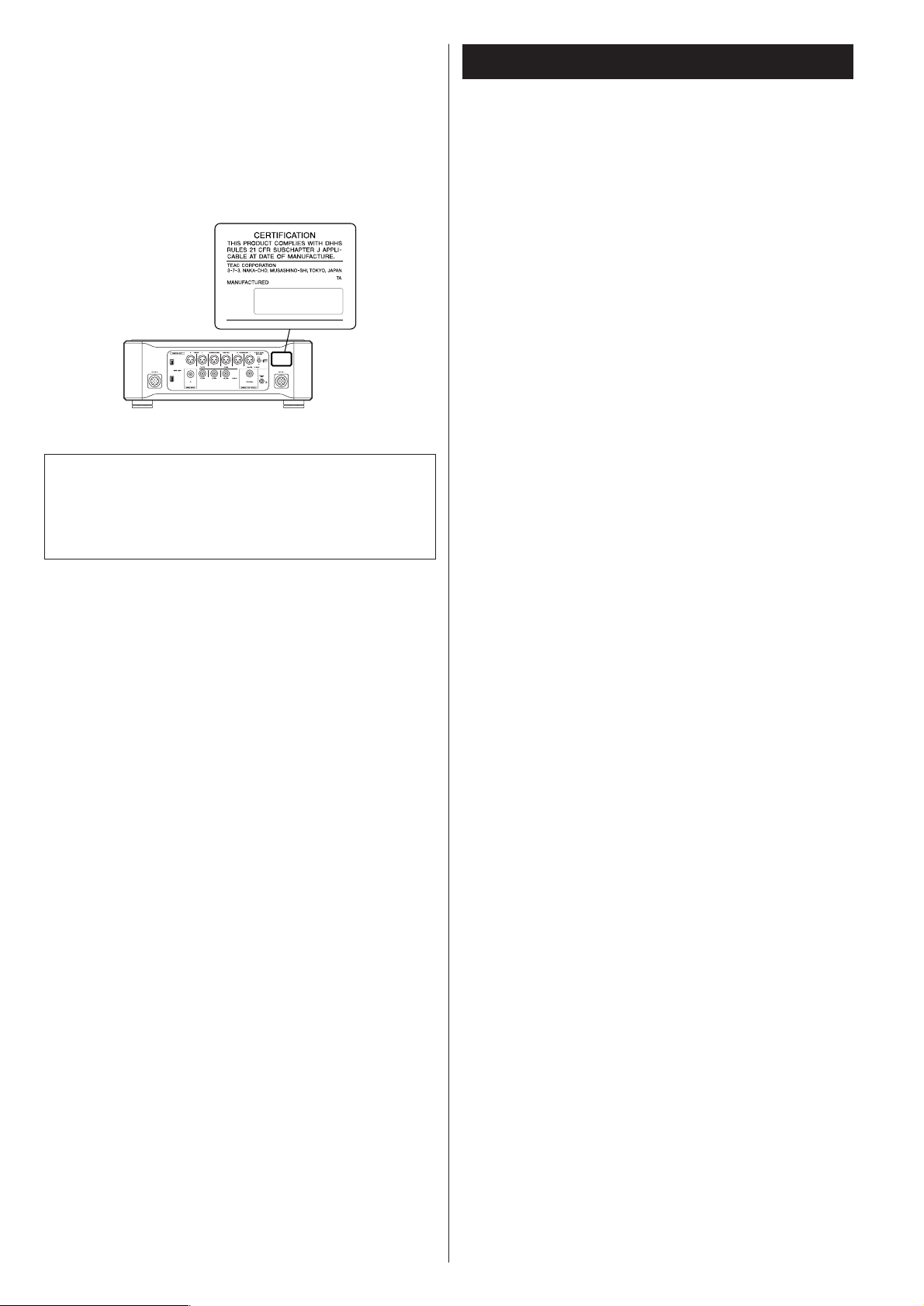
This product has been designed and manufactured according to
FDA regulations “title 21, CFR, chapter 1, subchapter J, based on
the Radiation Control for Health and Safety Act of 1968“, and is
classified as class 1 laser product. There is not hazardous invisible
laser radiation during operation because invisible laser radiation
emitted inside of this product is completely confined in the
protective housings.
The label required in this regulation is shown
①.
For U.S.A.
①
Contents
Thank you for choosing Esoteric. Read this manual
carefully to get the best performance from this unit.
VARING: APPARATEN INNEHÅLLER LASER KOMPONENT MED
STRÅLNING ÖVERSTIGANDE KLASS 1.
“ADVARSEL: USYNLIG LASERSTRÅLING VED ÅBNING NAR
SIKKERHEDSAFBRYDERE ER UDE AF FUNKTION. UNDGÅ
UDSAETTELSE FOR STRÅLING”
“VAROITUS! SUOJAKOTELOA EI SAA AVATA. LAITE SISÄLTÄÄ
LASERDIODIN. JOKA LÄHETTÄ (NÄKYMÄTÖNTÄ) SILMILLE
VAARALLISTA LASERSÄTEILYÄ”.
ADVARSEL: USYNLIG LASERBESTRÅLING NÅR DENNE DELEN ER
ÅPEN OG SIKKERHETSSPERREN ER UTKOBLET UNNGÅ
UTSETTELSE FOR STRÅLING.
Features . . . . . . . . . . . . . . . . . . . . . . . . . . . . . . . . . . . . . . . . . . 4
Before Use . . . . . . . . . . . . . . . . . . . . . . . . . . . . . . . . . . . . . . . . 5
Connections . . . . . . . . . . . . . . . . . . . . . . . . . . . . . . . . . . . . . . . 6
Connection to the D-01 (XLR). . . . . . . . . . . . . . . . . . . . . . . . 8
Connection to the D-01 (IEEE1394) . . . . . . . . . . . . . . . . . . 10
Connection to the D-70 . . . . . . . . . . . . . . . . . . . . . . . . . . . 11
i.LINK (IEEE 1394) . . . . . . . . . . . . . . . . . . . . . . . . . . . . . . . . 12
Remote Control Unit. . . . . . . . . . . . . . . . . . . . . . . . . . . . . . . . 13
Names of Each Control (Main Unit). . . . . . . . . . . . . . . . . . . . . 14
Names of Each Control (Remote Control Unit) . . . . . . . . . . . . 16
Discs. . . . . . . . . . . . . . . . . . . . . . . . . . . . . . . . . . . . . . . . . . . . 17
Basic Operation. . . . . . . . . . . . . . . . . . . . . . . . . . . . . . . . . . . . 18
Playback . . . . . . . . . . . . . . . . . . . . . . . . . . . . . . . . . . . . . . . . . 19
Skipping playback. . . . . . . . . . . . . . . . . . . . . . . . . . . . . . . . . . 20
Selecting a track . . . . . . . . . . . . . . . . . . . . . . . . . . . . . . . . . . . 20
Fast scanning . . . . . . . . . . . . . . . . . . . . . . . . . . . . . . . . . . . . . 21
Selecting the playback area. . . . . . . . . . . . . . . . . . . . . . . . . . . 21
Programmed playback . . . . . . . . . . . . . . . . . . . . . . . . . . . . . . 22
Repeat mode . . . . . . . . . . . . . . . . . . . . . . . . . . . . . . . . . . . . . 23
2 channel/Multi channel . . . . . . . . . . . . . . . . . . . . . . . . . . . . . 23
Changing the display mode . . . . . . . . . . . . . . . . . . . . . . . . . . 24
Display dimming . . . . . . . . . . . . . . . . . . . . . . . . . . . . . . . . . . . 24
Word Sync . . . . . . . . . . . . . . . . . . . . . . . . . . . . . . . . . . . . . . . 25
Up Convert. . . . . . . . . . . . . . . . . . . . . . . . . . . . . . . . . . . . . . . 25
Settings (introduction). . . . . . . . . . . . . . . . . . . . . . . . . . . . . . . 26
Audio Setup . . . . . . . . . . . . . . . . . . . . . . . . . . . . . . . . . . . . 28
Speaker Setup . . . . . . . . . . . . . . . . . . . . . . . . . . . . . . . . . . 28
Troubleshooting . . . . . . . . . . . . . . . . . . . . . . . . . . . . . . . . . . . 30
Specifications . . . . . . . . . . . . . . . . . . . . . . . . . . . . . . . . . . . . . 31
Block Diagram . . . . . . . . . . . . . . . . . . . . . . . . . . . . . . . . . . . . 32
Page 4

4
Features
Newest Generation VRDS mechanism for SACD (employing a
magnesium turntable and SS400 bridge)
The VRDS mechanism securely clamps the disc to the turntable,
the diameter of which is exactly the same as that of the disc. This
system completely eliminates vibration inherent to removable
media and unwanted vibrations generated by the mechanical
systems. Also, this mechanism clamps the discs at a slight
inclination so as to compensate for warping or deformation
improving the accuracy of the optical axes of both the laser pickup and the pit surface of the disc. This is effective in reducing the
errors in reading the disc data as well as in preventing timing
errors from erratic data acquisition timing.
The P-01 utilizes a magnesium turntable. Magnesium, with a
specific gravity two-thirds that of aluminum, is lightweight and
has excellent vibration absorption properties that help achieve
high-speed rotation with extraordinary stability which are
required by an SACD player. What’s more, a pair of highly precise
ball bearings is used in the spindle shaft bearing unit and 20-mm
thick SS400 steel is used for the support bridge that is directly
joined to a 10-mm thick iron frame structure.
Coreless motor using neodymium magnets
ESOTERIC has developed a new, long-life three-phase brushless
spindle motor for high-speed rotation of the large diameter
turntable. In cooperation with the turntable firmly held in place
with high-precision ball bearings, this motor minimizes rotation
irregularities and vibrations.
Completed through scientific validations including magnetic field
analysis, the optimized magnetic circuit reduces fluctuations in
the motor drive current, thereby lessening any effects on audio
circuits.
Pickup structure designed to prevent tilting of the laser
optical axis and speed feedback-controlled sled transport
The pickup used in the P-01 has a highly rigid sliding-shaft
structure that prevents the lens from tilting and the laser optical
axis is kept precisely aligned with the media’s bit track. In the sled
moving mechanism a proprietary Hall element sensing-type threephase brushless motor is used and powerful electronic speed
feedback circuits control this sled mechanism for quick access,
thereby ensuring smooth, continuous lens movement with
superior response.
Highly rigid chassis to completely eliminate internal and
external vibrations that might deteriorate sound quality
The chassis that supports the mechanisms includes steel bottom
frame of 10-mm thickness and 4.52-kg (10 lbs) of weight. Thick
aluminum is used on the top, side, bottom and front panels. The
entire chassis is supported by Esoteric-exclusive pinpoint feet
(patent pending) made of case-hardened tool steel.
Total attention is given to precision in mounting mechanical
parts, the rigidity of the housing, and eliminating sympathetic
vibration. The front and side panels constructed of thick brushed
aluminum, and the rounded four corners, also of aluminum,
create a feeling of dignity and gravitas, befitting of a superior
SACD/CD drive unit.
Power supply section completely separated from main body
To exploit the transport potential to the full, the power supply
unit is separated from the P-01 itself. The - power supply unit is
equipped with three transformers: one for driving the
mechanisms and motors, one for handling control signals so that
the pick-up reads disc data with superior accuracy, and one for
handling digital signals in the clock circuit and other areas. WB
transformers, remarkable for small current loss and quick
response, are used for driving the mechanism motors and for
handling digital signals.
Upward conversion on CD playback
The digital audio is sent through a high-precision crystal oscillator
that generates ±3ppm of accuracy (temperature characteristics
included) and DSRLL III circuit to minimize jitter and do upward
conversion.
The upward conversion feature makes it possible to output a
maximum 192kHz signal when playing back CDs. When playing
back SACD discs, the DSD signal (1 bit, 64 Fs) is sent out as
acquired without upconverion or other processing.
Digital audio output
The output stage includes one multi-function XLR system (six
terminals: L, R, C, SW, LS, and RS are available for ES-LINK
output; two terminals: L and R for Dual AES output; and L/R
terminals for XLR output), one RCA system (L/R terminals), and
two IEEE 1394 systems. As an output having no upward
conversion function, one RCA (NORMAL) system is provided.
No SACD data is available at the RCA jack.
Esoteric-exclusive format, ES-LINK, making SACD digital
output possible
The SACD digital output is sent out of the XLR terminals in the
Esoteric-exclusive ES-LINK format, or out of the IEEE 1394
interface.
When “XLR DUAL” is selected as output and an SACD disc is
played , the output is automatically sent in the ES-LINK format.
Only the Esoteric mono D/A converter, the D-01, is ready for ESLINK at this time.
WORD SYNC
The word sync feature allows this unit to synchronize with an
external word clock. The input frequency is switch-selectable
between 44.1, 88.2, 176.4, 48, 96, 192, and 100 kHz. The P-01
is designed so that the phase shift between the word clock and
output sampling frequency is kept within 10 degrees when there
is no discrepancy between the two. This unit can be either in
“IN” mode or in “Rb IN” mode. When in Rb IN mode, a PLL
circuit devoted to a highly precise clock like the rubidium
controlled oscillator used in the ESOTERIC G-0s is activated.
Copper wires of 6N purity are used for primary internal
wirings, Further contributing to superior sound quality
High purity 6N copper wires are used for the supplied AC power
cord and most internal wiring that has effect on the sound quality
thereby improving the purity and texture resolution of the sound.
The insulating sheath is made of polyorefin, a non-PVC material,
used out of consideration for the environment as well as sound
quality. No PVC is used for any other wire insulation. The high
purity 6N copper cable is developed with the help of Acro Japan
Ltd. who also developed the highly acclaimed Esoteric “MEXCEL”
interconnection cable and high purity 8N copper cable.
Page 5
5
What’s in the box
Please confirm that the following accessories are in the box
when you open it.
Power cord x 1
DC power cable x 2
Screwdriver x 1
Remote control unit x 1
Batteries (AA, R6 or SUM-3) x 2
Felt pad x 8
Owner’s manual x 1
Warranty card x 1
Conventions about This Manual
< The types of functions and operations that can be used for a
particular disc vary depending on the features built into that
disc. In some cases, these functions and operations may differ
from the descriptions given in this Owner’s Manual.
<
The drawings about the front panel display used in this
Owner’s Manual are purely for the purposes of explanation.
The actual displays may differ slightly from what are shown
here.
Read this before operation
< As the unit may become warm during operation, always leave
sufficient space around the unit for ventilation.
<
The voltage supplied to the unit should match the voltage as
printed on the rear panel. If you are in any doubt regarding
this matter, consult an electrician.
<
Choose the installation location of your unit carefully. Avoid
placing it in direct sunlight or close to a source of heat. Also
avoid locations subject to vibrations and excessive dust, heat,
cold or moisture.
<
Do not place the unit on the amplifier/receiver.
<
Do not open the cabinet as this might result in damage to the
circuitry or electrical shock. If a foreign object should get into
the unit, contact your dealer or service company.
<
When removing the power plug from the wall outlet, always
pull directly on the plug, never yank the cord.
<
To keep the laser pickup clean, do not touch it, and always
close the disc tray.
<
Do not attempt to clean the unit with chemical solvents as
this might damage the finish. Use a clean, dry cloth.
<
Keep this manual in a safe place for future reference.
DO NOT MOVE THE UNIT DURING PLAYBACK
During playback, the disc rotates at high speed. Do NOT lift or
move the unit during playback. Doing so may damage the
disc or the unit.
WHEN MOVING THIS UNIT
When changing places of installation or packing the unit for
moving, be sure to remove the disc and return the disc tray to
its closed position in the player. Then, press the power switch
to turn the power off, and disconnect the power cord.
Moving this unit with the disc loaded may result in damage to
this unit.
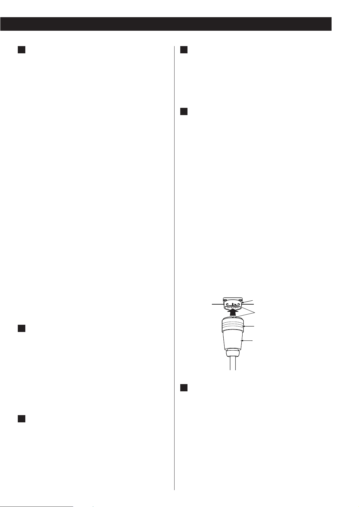
Before Use
Placement of the unit
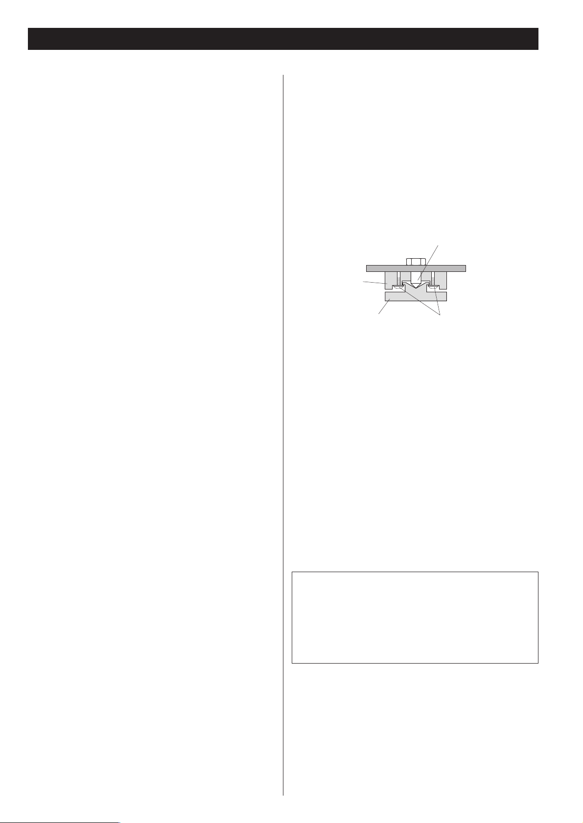
High-quality hardened tool steel is used for the pin-point feet
attached to the bottom of the player. Although the outer feet
may appear loose, the weight of the unit causes them to
become firm and secure. The design effectively damps and
reduces vibration.
<
WARNING: Be careful to avoid injury when moving the unit.
This unit weighs over 60 pounds! Seek assistance when
moving or placing this product.
<
To protect the supporting furniture surface, you may stick the
felt pads supplied with the unit to the bottom of the metal
feet.
Pin-point foot
Bottom plate
of the unit
Steel foot
Cover foot retaining screws
Cover foot
CAUTION
The product should not be exposed to dripping or splashing
and that no object filled with liquids, such as vases, shall be
placed on the product.
Do not install this equipment in a confined space such as a
book case or similar unit.
Beware of condensation
When the unit (or a disc) is moved from a cold to a warm
place, or used after a sudden temperature change, there is a
danger of condensation; vapor in the air could condense on
the internal mechanism, making correct operation impossible.
To prevent this, or if this occurs, leave the unit for one or two
hours with the power turned on. Then the unit will stabilize at
the temperature of its surroundings.
Maintenance
If the surface of the unit gets dirty, wipe with a soft cloth or
use diluted neutral cleaning liquid. Be sure to remove any
fluid completely. Do not use thinner, benzine or alcohol as
they may damage the surface of the unit.
Frame
Page 6
6
Connections
CAUTION:
<
Switch off the power to all equipment before making connections.
<
Read the instructions of each component you intend to use with this unit.
<
Be sure to insert each plug securely. To prevent hum and noise, avoid bundling the
signal interconnection cables together with the AC power cord or speaker cables.
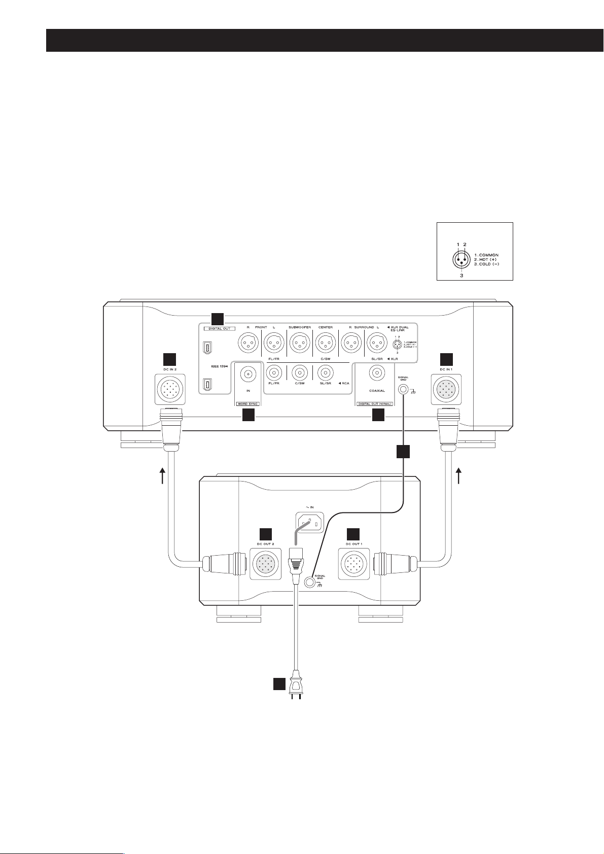
EE
E E
F
A
D
BC
Direction of the arrow
printed on the DC power
cable
Direction of the arrow
printed on the DC power
cable
Main Unit
Power Supply Unit
XLR pin assignment
Supplied power cord
Page 7
7
Digital audio output terminals
Digital audio is output from these terminals.
Connect these terminals to the digital input terminals of D/A
converters (D-01) using commercially available cables.
XLR: Use balanced XLR digital audio cable
COAXIAL: Use RCA (pin) digital audio cable
IEEE1394 / i.LINK (AUDIO):
Use S400 compatible IEEE1394 6pin cable
To output digital surround sound from SACD discs, the
ES-LINK compatible D/A converter, or an IEEE1394
(i.LINK S400 (AUDIO)) compatible D/A converter is
necessary.
See pages 8-11 for details on the connection to the
Esoteric D-01 or TEAC D-70.
If your D/A converter doesn’t have an IEEE1394 terminal nor
ES-LINK terminal, connect P-01’s FL/FR terminal (XLR or RCA)
to the digital input terminal of the D/A converter. In this
case, the P-01 cannot output digital sound from SACD.
<
The IEEE 1394 terminal is an interface capable of bidirectional data transmission with a connected device. You
don’t need to be concerned with distinguishing between
input and output.
<
No digital output is available at the RCA C/SW and LS/RS
terminals at this time. If no ES-LINK-capable device is
connected, no digital output is available at the XLR C/SW
and LS/RS terminals, either. When updated in the future,
this unit will have the capability of outputting multi-channel
digital audio coming from DVD-Audio sources.
Digital audio output terminals (NORMAL)
Conventional digital audio from CD is output from this
terminal. Connect this terminal to the digital input terminal
of a digital device using a commercially available RCA digital
audio cable.
<
When you are using this terminal, select ON in the “D-OUT
Norm” setting (see page 28).
<
This terminal cannot output digital sound from SACD discs.
<
This terminal cannot output up-converted signals.
Word sync input terminal
This allows the use of an externally generated word clock
connection, using a commercially available BNC coaxial
cable (75Ω).
Devices producing such a suitable clock signal include
external D-A converters, or dedicated word clock
generators. Connect the WORD SYNC OUT of such a device
to the unit.
C
B
A
SIGNAL GND connection
Use a commercially available PVC-covered cord to connect
the signal ground terminal on the unit to the amplifier signal
ground.
<
Note that this is NOT an electrical safety ground (earth).
DC IN/OUT connector
Connect the DC OUT connectors of the power supply unit
to the DC IN connectors of the main unit using the supplied
DC power cables.
DC OUT 1 q
DC IN 1
DC OUT 2 q
DC IN 2
<
The DC power cables carry arrow marks on them. Connect
them so that the arrows point as shown on the opposite
page. Making sure of the position of the cut-out in the end of
the plug and the direction of the arrow on the DC power
cable, hold the body of the plug, align the cut-out with the
guide mark on the connector and inset the plug until it clicks
in and locks in place. When unplugging the cable, firmly
grasp the barrel or locking ring around the end of the plug
and pull directly toward you. Do not push or pull the plug at
an angle when plugging or unplugging the cable.
<
Always switch off the power before plugging or unplugging
the DC power cable.
< Be careful not to get your fingers pinched between the end of
the plug and the connector.
E
D
Power cord receptacle
After all other connections have been made, insert the
supplied AC power cord into this receptacle, then connect
the other end of the power cord into the AC power source.
Ensure that your AC voltage corresponds to the voltage
marked on the rear panel of the unit. Consult a qualified
electrician if you are in doubt.
<
In order to avoid the risk of electric shock, fire, or other
hazard, only use the supplied power cord or a suitably
approved OEM power cord.
<
If you are not going to use the unit for some time,
disconnect the power cord from the wall socket.
F
Connector
Align using this mark.
Grasp the ring and pull toward you
to unplug the cable.
Plug
Page 8
8
Connection to the D-01 (XLR)
AUDIO IN
(FRONT L)
Amplifier
AUDIO IN
(FRONT R)
Amplifier
D-01 (FRONT L)
D-01 (FRONT R)
G-0/G-0s
P-01
Connection to the G-0/G-0s and two D-01 converters
XLR digital cable
BNC coaxial cable
XLR cable
XLR cable
When connecting the clock
generator G-0 or G-0s, connect
the WORD CLOCK OUT of the
G-0/G-0s to the WORD SYNC IN
of the P-01 and D-01.
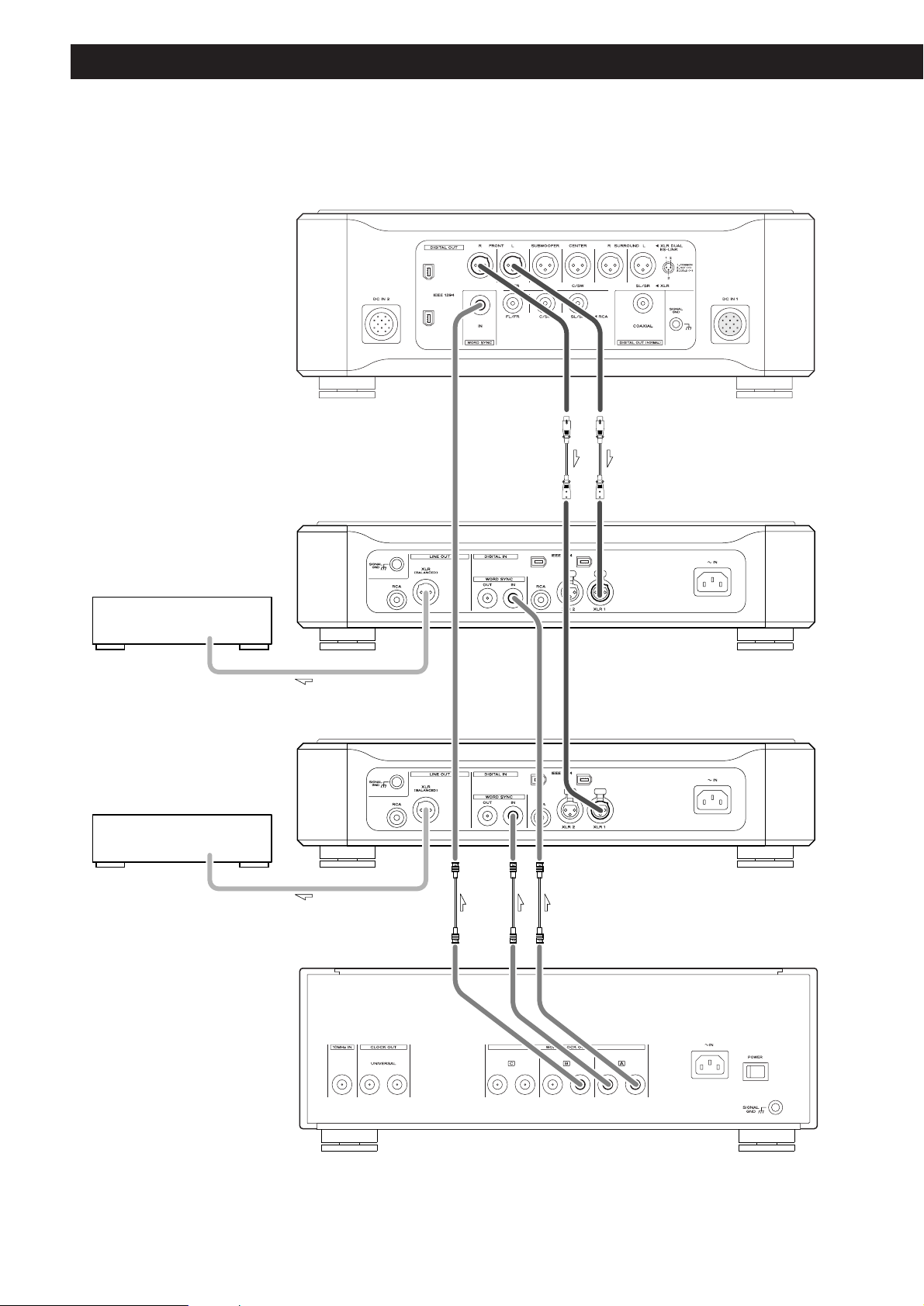
Page 9
9
WORD
SYNC
OUT
WORD
SYNC
IN
WORD
SYNC
OUT
XLR 1 XLR 1
XLR 1 XLR 1
D-01(R)
D-01(L)
D-01(SUBWOOFER) D-01(CENTER)
D-01(SURROUND R)
D-01(SURROUND L)
WORD
SYNC
OUT
WORD
SYNC
IN
WORD
SYNC
OUT
WORD
SYNC
IN
XLR 1 XLR 1
WORD
SYNC
OUT
WORD
SYNC
IN
WORD
SYNC
OUT
WORD
SYNC
IN
BNC coaxial cable
XLR digital cable
When connecting to two D-01 units, connect the XLR terminals
(FRONT L and FRONT R) of the P-01 to the XLR terminal (1 or 2)
of each D-01.
When you are using six D-01 units for multi-channel listening,
connect their XLR outputs in a similar way.
If the clock generator G-0/G-0s isn’t available, connect the word
sync terminals as shown above (in random order).
When connecting the G-0 or G-0s with a P-01 and six D-01
units, connect the WORD CLOCK OUT of the G-0/G-0s to the
WORD SYNC IN of each D-01 and connect the UNIVERSAL
CLOCK OUT of the G-0/G-0s to the WORD SYNC IN of the P-01.
Setting of the P-01
OUTPUT button “XLR DUAL”
WORD button
“IN” (When the G-0s is connected, “Rb IN”)
UP CONVERT button
“176.4/192”
Setting of the D-01
INPUT button “XLR 1” or “XLR 2”
WORD button One of the D-01 that outputs word
synchronization signals: “OUT”
The others: “IN”
When the G-0 is connected, set all the
D-01s to “IN”.
When the G-0s is connected, set all the
D-01s to “Rb IN”.
W_OUT setting “176.4”
CH_SEL setting respective channels
Setting of the G-0/G-0s
Frequency change button (A, B or C) 176.4kHz
FREQUENCY MODE button 44.1kHz
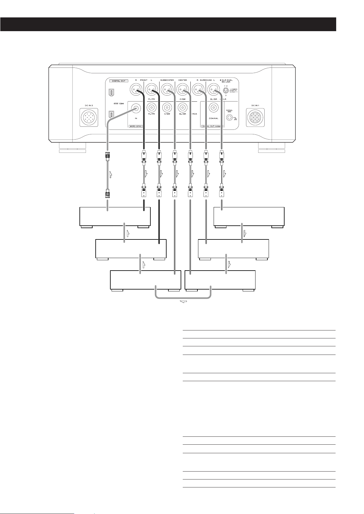
Connection to 6 sets of D-01
Page 10
10
Connection to the D-01 (IEEE1394)
WORD
SYNC
OUT
WORD
SYNC
IN
IEEE 1394
IEEE 1394
WORD
SYNC
OUT
WORD
SYNC
IN
IEEE 1394
IEEE 1394
D-01
(L)
D-01
(R)
WORD
SYNC
OUT
WORD
SYNC
IN
IEEE 1394
IEEE 1394
D-01
(SUBWOOFER)
WORD
SYNC
OUT
WORD
SYNC
IN
IEEE 1394
IEEE 1394
D-01
(CENTER)
WORD
SYNC
OUT
WORD
SYNC
IN
IEEE 1394
IEEE 1394
D-01
(SURROUND L)
WORD
SYNC
OUT
IEEE 1394
D-01
(SURROUND R)
Six D-01 units are required in order to play multi-channel
SACD layers on Hybrid discs without mixing them down to
stereo.
When connecting two D-01 units, connect either IEEE 1394
terminal on the P-01 to the same labeled terminal on the D-01.
In addition, connect the remaining IEEE 1394 terminal on the D01 to the same labeled terminal on the next D-01.
If you are using six D-01 units, daisy-chain all the remaining units
in a similar way (in random order).
For the word sync terminals, connect them as shown (in random
order).
When connecting the clock generator G-0s, connect the six
WORD CLOCK OUT terminals to the WORD CLOCK IN on each
unit, and connect the UNIVERSAL CLOCK OUT on the G-0s to
the WORD SYNC IN on the P-01.
Setting of the P-01
OUTPUT button “IEEE 1394”
WORD button
“IN” (When the G-0s is connected, “Rb IN”)
UP CONVERT button
“176.4/192”
Setting of the D-01
INPUT button “IEEE 1394”
WORD button One of the D-01 that outputs word
synchronization signals: “OUT”
The others: “IN”
When the G-0s is connected, set all the
D-01 to “Rb IN”.
W_OUT setting “176.4”
CH_SEL setting respective channels
Setting of the G-0s
Frequency change button (A, B or C) 176.4kHz
FREQUENCY MODE button 44.1kHz
BNC coaxial cable
IEEE 1394 cable
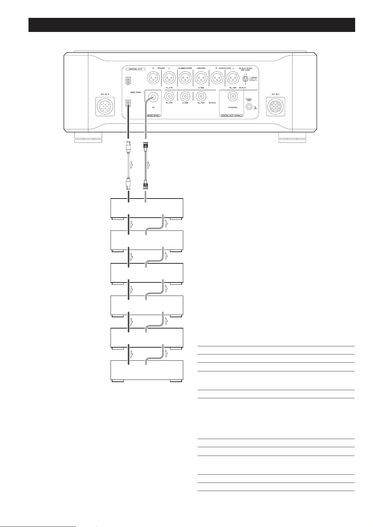
Page 11

11
Connection to the D-70
WORD
SYNC
OUT
XLR 2
(L)
XLR 1
(R)
D-70
RCA
DIGITAL IN
When connecting a single D-70, connect the XLR outputs
(FRONT L and FRONT R) on the P-01 to the digital inputs (XLR 1
and XLR 2) on the D-70.
If you don’t have XLR digital cables, you may use an RCA coaxial
cable to make the connection between the FL/FR output on the
P-01 and the digital inputs (RCA) on the D-70.
You also need to connect the WORD SYNC OUT on the D-70 to
the WORD SYNC IN on the P-01.
Setting of the P-01
OUTPUT button “XLR DUAL”
WORD button
“IN” (When the G-0s is connected, “Rb IN”)
UP CONVERT button
“176.4/192”
Setting of the D-70
INPUT SELECTOR “XLR”
AES3 INPUT “DUAL”
Word sync setting “88.2”
BNC coaxial cable
XLR digital cable
RCA coaxial cable
Page 12

12
i.LINK (IEEE 1394)
The i.LINK is also known as IEEE 1394, an international
specification.
This unit is already configured for i.LINK (AUDIO).
By connecting an i.LINK (AUDIO)-capable device to the IEEE 1394
(or i.LINK (AUDIO)) terminal on this unit using an i.LINK cable,
you can transmit SACD multi-channel digital signals that could
not be transmitted in the past. Previously only the analog signal
could be transmitted. With the i.LINK format, the P-01 can
transmit in native DSD as well as transmitting 2-ch linear PCM
data and multi-channel compressed audio signals.
If you have multiple i.LINK-capable devices, you can connect
them through other devices to transmit data between them, so
you don’t need to be concerned with the order of connection.
Copyright protection system DTCP
To play back audio sounds recorded on SACD or DVD discs using
i.LINK, both the player and the D/A converter need to be ready
for the copyright protection system DTCP (Digital Transmission
Content Protection).
This unit is already configured for DTCP.
Data transfer rate
There are three transfer rates: 100 Mbps (S100), 200 Mbps
(S200), and 400 Mbps (S400). This unit is capable of transferring
data at a maximum 400Mbps.
For connection to an i.LINK-capable device, use a commercially
available S400-compliant 6-pin i.LINK cable.
When connecting multiple i.LINK-capable devices, avoid
connecting a device having slow transfer rate between devices
having high transfer rates since this reduces the transfer rate of
your whole system. Connect devices having high transfer rate
towards the source as far upstream as possible.
NOTES
<
Among the i.LINK formats there are “MPEG-2 TS” for SAT
digital source and “DV” for digital video for DVD recorders,
as well as the “i.LINK (AUDIO)” (A&M Protocol). Never
connect devices that are not ready for i.LINK (AUDIO) to this
unit. If you do, this unit and others may operate out of order
or possibly be damaged.
<
In the process of data transfer, avoid plugging/unplugging the
i.LINK cables while in use or switch the power off before
making or breaking connections.
<
Among the i.LINK-capable devices there are some that, if not
turned on, are not capable of relaying data.
< Chances are some i.LINK-capable devices will not respond to
this unit’s command.
How to connect multiple i.LINK-capable
devices
Daisy chain connection
You can daisy-chain up to 17 devices including this unit.
Connection in tree structure
If you are using a device having three or more i.LINK connectors,
you may want to get the connection branched out. This way of
connection allows you to connect up to 17 devices including this
unit.
Your system does not work if data is fed back to the output
device. Be careful not to create a loop.
i.LINK-capable
device
i.LINK-capable
device
i.LINK-capable
device
i.LINK-capable
device
i.LINK-capable
device
i.LINK-capable
device
i.LINK-capable
device
i.LINK-capable
device
i.LINK-capable
device
i.LINK-capable
device
i.LINK-capable
device
i.LINK-capable
device
i.LINK cable
i.LINK-capable
device
i.LINK-capable
device
i.LINK-capable
device
The i.LINK interface of this unit is designed in accordance with
the following specifications:
1)IEEE Std 1394a-2000, Standard for a High Performance
Serial Bus
2) Audio and Music Data Transmission Protocol 2.0
This unit is compliant with IEC 60958 bitstream, DVD-Audio,
SACD in the AM824 sequence adaptation layers of this
protocol.
The i.LINK logo is a trademark of Sony Corporation, registered in
the U.S. and other countries.
Page 13

13
Remote Control Unit
Battery Replacement
If the distance required between the remote control unit and
main unit decreases, the batteries are weak. If this is the case,
replace the batteries with fresh ones.
Precautions concerning batteries
<
Be sure to insert the batteries with correct positive “+” and
negative “_
” polarities.
<
Use batteries of the same type. Never use different types of
batteries together.
< Rechargeable and non-rechargeable batteries can be used.
Refer to the precautions on their labels.
< When the remote control unit is not to be used for a long
time (more than a month), remove the batteries from the
remote control unit to prevent them from leaking. If they
leak, wipe away the liquid inside the battery compartment
and replace the batteries with new ones.
<
Do not heat or disassemble batteries and never dispose of old
batteries by throwing them in a fire.
How to insert the batteries
Remove the cover of the remote control unit with a
screwdriver. After checking the polarity (+
/_) of two AA
batteries, insert the batteries, replace the cover and replace
the screws.
Notes on use
<
Point the remote control unit at the player’s remote sensor
and use it within seven meters (20 feet) of the player. There
should not be any obstacles between the player and the
remote control unit.
<
Do not allow direct sun or other light to shine on the remote
sensor part of the player. This may cause the remote control
unit to work incorrectly.
<
Note that other units with remote controls may operate
incorrectly because of infrared light “overspill” when you
operate this remote control unit.
Remote Sensor
7m
Page 14

14
Names of Each Control (Main Unit)
L
A B C D E F HG KI J
a
b
c
g
h
j
ik
d
e
f
Page 15

15
Display
Disc type indicator (SACD or CD)
Shows the type of disc currently loaded.
TRACK indicator
Indicates that the track number of a CD or SACD is being
shown.
TOTAL indicator
Indicates that the total time is being shown.
REMAIN indicator
Indicates that the remaining time is being shown.
DOWN MIX indicator
Lights to show that a multi-channel source has been
downmixed.
5.1CH indicator
Lights to show that “Multi ch” has been selected
Channel indicators
Light to show which surround channels are currently in use.
Message area
Alphanumeric display to show times, status messages, etc.
REPEAT indicator
Lights when repeat play is selected
Pause indicator
Lights when playback is paused.
Playback indicator
Lights when playing back.
k
j
i
h
g
f
e
d
c
b
a
Front Panel
OUTPUT
Use this button to select the digital output terminals.
The indicator of the selected terminal lights.
WORD
Use this button to turn on or off the word sync function.
When the word sync is on (“IN” or “Rb IN”), the unit will
synchronize with an external word sync source.
The indicator of the selected mode will be lit.
No indicator is lit when the word sync function is off.
UP CONVERT
Use this button to up convert the sampling frequency.
The indicator of the selected frequency lights.
Remote control sensor
Receives signals from the remote control unit. Point the
remote control unit at this sensor when operating the remote
control unit.
Display
Disc tray
OPEN/CLOSE
Use this button to open and close the disc tray.
STOP
Use this button to stop playback.
PLAY
Use this button to start playback. The PLAY indicator lights
during playback.
PAUSE
Use this button to pause playback. The PAUSE indicator lights
during pause.
SKIP (.//)
Use these buttons for skip operations. Pressing and holding
these buttons for more than a second changes the scanning
speed.
POWER
Use this button to turn the unit on or off. When the unit is
on, the ring surrounding the button lights up.
L
K
J
I
H
G
F
E
D
C
B
A
The equipment draws nominal non-operating power from
the AC outlet with its POWER switch in the OFF position.
Page 16

16
Names of Each Control (Remote Control Unit)
STOP
Use this button to stop playback.
PLAY
Use this button to start playback.
Cursor buttons and ENTER
Use these buttons to navigate in the setup mode.
SETUP
Use this button to enter or exit the setup menu.
OPEN/CLOSE
Use this button to open and close the disc tray.
CLEAR
Use this button to clear entry errors, etc.
DISPLAY
Use this button to change the display mode.
FL DIMMER
Use this button to change the brightness of the front panel
display and indicator lamps.
REPEAT
Use this button to set the repeat playback mode.
PROGRAM
Use this button when programming playback order.
SKIP (.//)
Use these buttons for skip operations.
PAUSE
Use this button to pause playback.
RETURN
Use this button to go back a level in the setup menu.
DAC OUTPUT LEVEL
If you have the Esoteric D-01, use these buttons to adjust the
output level.
Buttons for the operation of DVD-Audio
The following are the DVD-Audio-only buttons, and will be
made available when the P-01 is updated in the future.
AUDIO
During playback of a DVD-Audio disc, press this button to
select an audio.
GROUP
During playback of a DVD-Audio disc, press this button to
skip groups.
S
R
Q
P
O
N
M
L
K
J
I
H
G
F
E
A
Note:
To simplify explanations, instructions in this manual refer to
the names of the buttons and controls on the front panel
only. Associated controls on the remote control will also
operate similarly.
Number buttons
Use these buttons for selecting tracks by number, etc.
PLAY AREA
Use this button to select the playback area of SACD discs.
2CH/MULTI
Use this button to switch between two-channel (stereo) and
multi-channel surround audio output.
SCAN (m/,)
Use these for fast scanning during playback.
D
C
B
A
I
B
C
D
G
H
J
K
L
M
S
N
O
E
F
P
Q
R
Page 17

17
Discs
Audio CD:
• 12cm or 8cm discs
• Linear PCM digital audio
Audio CDs are divided into tracks.
SACD:
• Single layer, dual layer or Hybrid layer
• 12cm or 8cm discs
• Digital audio (DSD)
SACDs are divided into tracks.
Type of discs that can be played on this system
This player can playback discs bearing any of the following logos:
“Super Audio CD” is a registered trademark.
About CD-R/CD-RW
CD-R/RW discs recorded in Audio CD format and finalized
correctly are playable. But depending on the quality of the
disc and/or the condition of the recording, some CD-R & CDRW discs may not be playable.
Caution:
<
If you record a disc using a personal computer, even if it is
recorded in a compatible format, there are cases in which it
may not play because of the settings of the application
software used to create the disc. (Check with the software
publisher for more detailed information.)
<
Unfinalized CD-R/CD-RW discs cannot be played.
Following discs cannot be played with this
unit:
• DVD, CD-G, Data part of CD-EXTRA, PHOTO CD, CD-ROM
and DVD-ROM discs
• illegally produced discs
• scratched discs
• discs that are dusty, soiled or marked with fingerprints
Warning:
If you attempt to play back such discs, there is a risk that sudden
very loud noise will be sent to the speakers at full volume and
may cause damage to the speakers and possibly your hearing.
Copy-protected discs and other discs which do not conform to
the CD standard may not play back correctly in this player. If you
use such discs in this unit, TEAC ESOTERIC COMPANY cannot be
responsible for any consequences or guarantee the quality of
reproduction. If you experience problems with such nonstandard discs, you should contact the producers of the disc.
How to remove the disc How to hold the disc
< Always place the disc on the disc tray with the label side up.
(Compact discs can be played or recorded only on one side.)
<
To remove a disc from its storage case, press down on the
center of the case and lift the disc out, holding it carefully by
the edges.
<
Should the disc become dirty, wipe the surface radially (from
the center hole outward towards the outer edge) with a soft,
dry cloth:
Do not clean the disc using a circular motion around the disc.
<
Never use such chemicals as record sprays, antistatic sprays or
fluid, benzine or thinner to clean the discs. Such chemicals
will do irreparable damage to the disc’s plastic surface.
<
Discs should be returned to their cases after use to avoid dust
and scratches that could cause the laser pickup to “skip.”
<
Do not expose discs to direct sunlight or high humidity and
temperature for extended periods. Long exposure to high
temperatures will warp the disc.
<
Do not play any disc that is warped, deformed or damaged.
Playing such discs may cause irreparable harm to the playing
mechanism.
<
CD-R and CD-RW discs are more sensitive to the effects of
heat and ultraviolet rays than ordinary CDs. It is important
that they are not stored in a location where direct sunlight
will fall on them, and which is away from sources of heat
such as radiators or heat-generating electrical devices.
<
Printable CD-R and CD-RW discs aren’t recommended, as the
label side might be sticky and damage the unit.
<
Do not stick papers or protective sheets on the discs and do
not use any protective coating spray.
<
Use a soft oil-based felt-tipped pen to write the information
on the label side. Never use a ball-point or hard-tipped pen,
as this may cause damage to the recorded side.
<
Never use a disc stabilizer. Using commercially available CD
stabilizers with this unit will damage the mechanisms and
may cause them to malfunction.
<
Do not use irregular shape CDs (octagonal, heart shaped,
business card size, etc.). CDs of this sort can damage the unit:
<
If you are in any doubt as to the care and handling of a CDR/CD-RW disc, read the precautions supplied with the disc, or
contact the disc manufacturer directly.
Page 18

18
Basic Operation
POWER switch Digital Output Setting
Press the POWER switch of the power supply unit to turn the
P-01 on or off.
When the unit is on, the ring surrounding the switch lights
up.
<
Also turn the connected components (D/A converter,
amplifier, clock generator, etc.) on.
< When the WORD button is set to “IN” or “Rb IN”, “WRD
UNLOCK!” or “No Word!” may appear, as it takes several
seconds for the unit to lock the word clock input from the
WORD SYNC IN terminal. The message will disappear when
the unit locks to the word clock.
Repeatedly press the OUTPUT button to select the digital
output terminal.
Select the terminal to which your D/A converter is connected.
The indicator of the selected terminal lights up.
The ES-LINK indicator lights only when you select XLR DUAL
with an SACD on the disc tray. It goes off when the unit is
turned off or a CD is loaded.
<
The ES-LINK is an Esoteric-exclusive format that makes SACD
digital output possible. Data from SACD is automatically
transmitted in the ES-LINK format when you switch the P-01
to the XLR DUAL output with the ES-LINK-ready D/A
converter D-01 connected to the XLR connector on the P-01.
Page 19

19
PLAYOPEN/CLOSE
Opening and closing the tray
Press the OPEN/CLOSE button.
1
The tray opens after a few seconds (this delay is normal and
due to the movement of internal mechanisms within the unit
before opening).
Insert the disc label side up.
3
< Make sure the disc is located in the center of the recess in the
tray in order to avoid any malfunction or jamming of the tray
or the unit.
Press the OPEN/CLOSE button again.
4
The tray closes. Take care to not pinch your fingers or other
objects in the moving tray.
The unit reads the disc (this may take a little time) and the
display shows “LOADING”.
Press the PLAY button to start playback.
5
Pausing playback
Press the PAUSE button to pause playback. J indicator lights
on the display.
Press PLAY or PAUSE to restart playback.
Stopping playback
Press the STOP button.
Pressing OPEN/CLOSE opens the tray if it is closed, and closes
it if it is open.
When the tray is opened during playback, it may take a few
seconds before the disc comes to a stop and is “unloaded”.
The tray will then open.
Playback
Page 20

20
Skipping playback
Press the SKIP button (. or /) repeatedly until the
desired track is found. The selected track will be played from
the beginning.
<
If the . button is pressed once during playback, playback
returns to the start of the current track. If it is pressed within
one second from the start of the track, playback returns to
the start of the previous track (so pressing the button twice in
quick succession will skip back two tracks, etc.).
<
If tracks are skipped while playback is paused or stopped,
playback is paused or stopped at the start of the selected
track.
<
In programmed playback mode, these buttons will move
between tracks in the programmed order.
Selecting a track
Use the number button to select tracks for playback. Use the
+10 button to enter the first digit of numbers greater than 9
(repeated presses will show 1-, 2-, 3- etc.) and the single digit
buttons (0 through 9) for the second digit, or single-digit
track numbers.
Playback starts from the selected track, regardless of whether
the number is selected during playback or playback is stopped
or paused.
Use the CLEAR button to clear mistaken entries.
Page 21
21
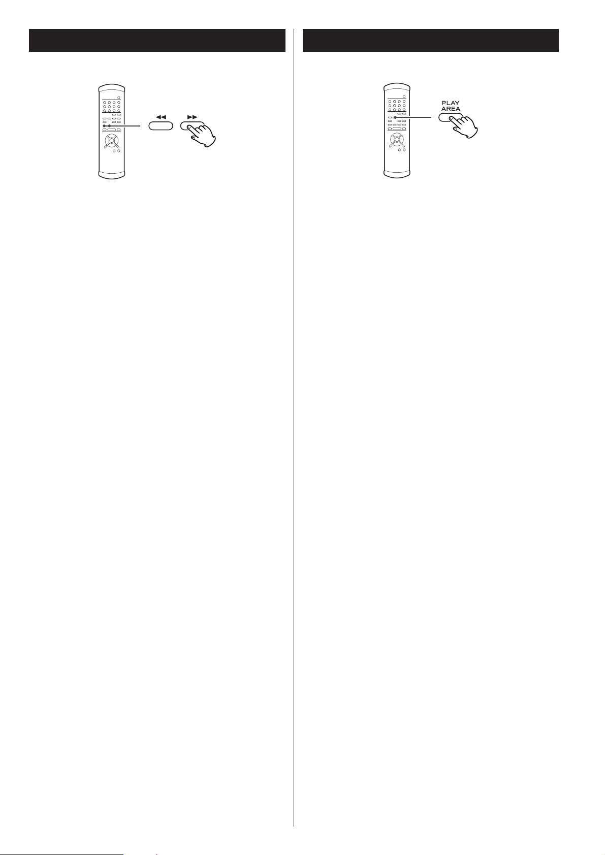
Some SACD discs contain two or more separate audio areas
such as multi-channel area, 2 channel (stereo) area and CD
area.
When playback is stopped, use the PLAY AREA button to
select the playback area.
Selecting the playback areaFast scanning
During playback, use the SCAN button (m or ,) to
rapidly move backwards and forwards. Press PLAY to restart
playback at normal speed at the desired location.
Repeated presses of the SCAN buttons changes the scanning
speeds. There are three speeds:
Fast (1) q
Fast (2) q Fast (3) q Play (normal speed)
<
You can also use the SKIP buttons on the front panel of the
main unit. To start scanning (or to change the scanning
speed), press and hold the SKIP button for more than one
second.
Notes
Scanning can be carried out across track boundaries.
If backward scanning reaches the start of the disc, playback
starts from the beginning. If forward scanning reaches the
end of the disc, scanning and playback stop.
Page 22

22
Programmed playback
Programmed playback allows up to 30 tracks to be played
back in the order you decide.
Press the PROGRAM button (either during playback or
when stopped).
If a track is currently playing back (or paused in the middle of
the track), this track is added as the first item in the
programmed playback list.
1
Use the number buttons to add tracks to the
programmed playback list.
2
Use the +10 button and 0 through 9 buttons in exactly the
same way as when selecting tracks.
Continue pressing the number buttons to add tracks.
<
Clear mistakes with the CLEAR button (the last entry is
cleared)
<
You can only select tracks on the disc (in other words, if the
disc has six tracks, you cannot program track 7).
Finish the programming by pressing PLAY.
Programmed playback begins (if the disc is actually being
played while you are setting the program order, there’s no
need to press PLAY).
3
Skip between tracks in the programmed playback order using
the SKIP buttons (.
//).
Clearing the last track from the list
Push the CLEAR button to clear the last track from the list.
Adding tracks to the list
Use the number buttons to add tracks to the list.
Clearing the whole program
Press the PROGRAM button to clear the program (playback
continues from the current point).
The OPEN/CLOSE or the POWER button also clears the
program.
Track number Number in programmed list
Page 23

23
Repeat mode
< Halting playback stops the repeat mode.
<
This feature is not available for all discs.
<
The following buttons cancel repeat mode:
STOP, OPEN/CLOSE, POWER.
Track repeat
When this is selected, the currently-selected track repeats. If
another track is selected during repeat playback, the newly
selected track repeats.
Disc repeat
The whole contents of the disc are repeated.
Programmed repeat
If programmed playback has been set up, the whole program
is repeated.
Pushing the REPEAT button cycles between REPEAT PGM
(program repeat) and REPEAT OFF (programmed playback
takes place).
Use the REPEAT button to select the repeat mode for
playback. Repeated presses of the REPEAT button cycle
between the following options:
REPEAT TRK
(repeat the track)
REPEAT DSC
(repeat the whole disc)
REPEAT OFF
(no repeat)
2 channel/Multi channel
When playback is stopped, use the 2CH/MULTI button to select
either 2CH (stereo) or MULTI (multi-channel surround) audio
output.
2ch
2-channel audio is output. When multi-channel data on SACD
is played back, the data from the center, sub-woofer, right
surround and left surround channels is mixed down to stereo
(front left and right channels). (The DOWN MIX indicator
lights on the display.)
Select this mode to listen music in stereo using two D-01
units.
Multi ch
Discrete 5.1-channel audio is output. Select this output mode
if you are using six D-01 units or the P-01 is connected to a
multi-channel D/A converter with IEEE 1394 cable.
<
The 5.1CH indicator lights when the P-01 is switched to Multi
ch.
Page 24

24
Display dimming
The display on the main unit can be dimmed to suit the
environment in which you listen to music. There are three levels
and an “off” setting.
Use the FL DIMMER button to cycle between these
settings.
<
Note that the OFF setting is not memorized when the power
is turned off. When the unit is switched off with the display
off, and then turned on again, the display is reset to the
minimum brightness.
<
In OFF mode, when you press a button such as PLAY, the
illuminations turn on temporarily.
Changing the display mode
During playback, it is possible to change the display as shown
here.
< When playback is stopped, the display shows “total number
of the tracks on the disc” and “the total playback time of the
disc”.
<
The DISPLAY button doesn’t work during programmed
playback.
Elapsed time of current trackCurrently playing track
Time remaining for current track
Total elapsed time (disc)
Total time remaining (disc)
Page 25

25
Word Sync Up Convert
< Select 44.1/48 kHz for no upward conversion.
<
The DSD signal (1 bit, 64 fs) from SACD is output as it is
without being up-converted.
< 88.2-kHz signals are sent out of each XLR terminal when you
select 176.4/192 kHz (4 times up sampling mode) with the
output set to XLR DUAL.
<
There is no audio output when you select 44.1/48 kHz with
the output set to XLR DUAL. The corresponding indicator
blinks in this case. In this case, select 88.2/96 kHz or
176.4/192 kHz.
<
No up-converted signal is available at the DIGITAL OUT
(NORMAL) terminal.
You can convert the basic 44.1/48kHz sampling frequency to
double (88.2/96kHz) or four times (176.4/192kHz).
Each press of the UN CONVERT button rotates the
selection through the following:
44.1/48kHz
88.2/96kHz (double)
176.4/192kHz (four times)
This feature is used when you want to get your whole system
locked to a single sync signal (clock) by connecting this unit to
the Esoteric D-01 or G-0/G-0s or other devices that are capable
of outputting a sync signal (word clock) or when you want to
use a precision external clock rather than the clock inside the P-
01.
Each press of the WORD button rotates the selection
through the following:
IN
This mode provides a stable sync operation with general
external clocks. But there are occasions when no sync can be
achieved depending on the output accuracy of the clocking
devices used.
This is because the word clock input frequency range of this
unit is set to as narrow as ±15ppm, a stability requirement in
order to achieve a sync with a high-degree of accuracy.
Rb IN
This is a mode designed for external clocks of higher degree
of precision like a rubidium clock generator.
Keep in mind that it will take time before synchronization is
achieved in this mode.
Switch the mode to IN if “WRD UNLOCK!” appears. This
means the stability of the connected clock is not accurate
enough for this sync mode.
Off
No word sync is available.
< Select Rb IN when connected to the G-0s, and select IN when
connected to the G-0/D-01/D-70.
<
This unit is ready for the following clocks and switches itself
depending on an incoming signal:
44.1 kHz, 48 kHz, 88.2 kHz, 96 kHz, 176.4 kHz, 192 kHz
This unit also accepts a Universal Clock frequency of 100
kHz.
<
When selecting IN or Rb IN, the corresponding indicator starts
blinking to indicate that the unit is searching for an external
clock. The indicator turns on solid (blue) when this unit
detects and locks to an external clock and is ready for play.
<
Make WORD SYNC connections before powering on the unit.
<
There are occasions where the D/A converter produces noise
when switching on/off the word sync. If this is the case
reduce the amplifier’s volume before going on.
Page 26

26
Settings (introduction)
Turn on the main unit.
1
Press the SETUP button to enter the setup menu.
2
“AudioSetup” appears on the front panel display.
<
In this manual, factory settings are marked with an asterisk
“*”.
< Although it is possible to enter the setup menu while
playback is continuing, not all menu functions will be
available. Increase the number of available functions by
pressing the STOP button.
<
Exit the setup menu by pressing SETUP once again.
Use the cursor buttons to navigate the menus.
3
When a option marked with “>” is displayed, use the up
or down cursor buttons to change the setting, and press
the ENTER button to confirm the entry.
4
Exit the setup menu by pressing SETUP once more.
5
< Refer to the Setup Menu Chart on the next page.
<
The options you can change are marked with “>”.
<
Use the left and up cursor buttons (or the RETURN button) to
go back a level in the setup menu.
<
When a numerical value (such as speaker distance) is
changed, the value is confirmed without pressing the ENTER
button.
<
Individual menu functions are described on pages 28 and 29.
<
Repeat steps and as required.
43
Restoring factory default settings
If you have made a lot of changes to the setup, and want to
restart from a known set of options, restore the unit to the
factory default settings as follows:
1. If the unit is on, press the POWER switch to turn it off.
2. While holding down the STOP button, press the POWER
switch.
All memories are erased, and the unit returns to the factory
default settings.
Power Supply Unit Main Unit
Page 27

27
Settings (introduction)
AudioSetup GeneralSet
2ch/Multi SP Setup
D-OUT Norm
CD Direct
SP Size
Distance L/R *.*m
C *.*m
SR/SL *.*m
SP Level
L/R Size
C Size
SR/SL Size
SW ON/OFF
LR ***.*dB
C ***.*dB
SR ***.*-dB
SL ***.*dB
SW ***.*dB
Test Start
Test Tone
options options
options
options
options
options
options
options
options
options
options
options
options
options
options
options
Page 28

28
Settings (Audio Setup)
2ch/Multi setting
When a option marked with “>” is displayed, use the up or
down cursor buttons to change the setting, and press the
ENTER button to confirm the entry.
2ch*
2-channel audio is output. Multi-channel data is mixed down
to stereo.
Select this mode to listen music in stereo when using only
two D-01 units or if the P-01 is connected to a two-channel
system.
Multi ch
Discrete 5.1-channel audio is output. Select this output mode
if you are using six D-01 units or the P-01 is connected to a
multi-channel D/A converter with IEEE 1394 cable.
Setting for the DIGITAL OUTPUT (NORMAL)
terminal (D-OUT Norm)
When a option marked with “>” is displayed, use the up or
down cursor buttons to change the setting, and press the
ENTER button to confirm the entry.
ON
Audio is output from the DIGITAL OUTPUT (NORMAL)
terminal. Select this when a digital device is connected to this
terminal.
OFF *
Audio is not output from the DIGITAL OUTPUT (NORMAL)
terminal. If you are not using this terminal, we recommend
you turn this OFF for better sound.
<
The DIGITAL OUTPUT (NORMAL) terminal cannot output an
up converted signal nor the SACD digital data stream.
CD Direct
When a option marked with “>” is displayed, use the up or
down cursor buttons to change the setting, and press the
ENTER button to confirm the entry.
Direct *
Speaker setting is bypassed. Select this setting for stereo
sound.
Normal
Select this to enjoy multi-channel sound using the speaker
setting you have selected.
Settings (Speaker Setup 1)
Speaker Size (SP Size)
Select the size (Large* or Small) independently for the L/R
(front pair of speakers), the C (center speaker) and the SR/SL
(surround pair of speakers). Turn the subwoofer (SW) ON* or
OFF (if you have no subwoofer).
Large *
Select this when the connected speakers can fully reproduce
low frequency sounds.
Small
Select this when the connected speakers are relatively small
and cannot fully reproduce low frequency sounds.
When this setting is selected, bass frequencies are output
from the subwoofer (if no subwoofer is connected, from the
front speakers).
OFF
Select this when no speaker is connected. The sound is
output from the front (or surround) speakers.
<
When the front speaker is set to “Small”, the subwoofer is
set to “ON” automatically. You cannot set the subwoofer
“OFF”.
ON (subwoofer only)
Select this when a subwoofer is connected.
< For the center and surround pair options, if these speakers are
not physically present, you can select OFF to prevent any
output from those channels (you cannot turn off the front L/R
pair). Any speakers turned off will downmix (if this option is
selected) to the other enabled channels.
Speaker levels (SP Level)
Use this to set the relative levels of the speakers. You can set
the L/R pair together, and the center, and surround rear pair
independently, as well as the subwoofer. The maximum value
you can set here is +6dB and the minimum is –12dB, with
settings made in 0.5dB increments. The default setting is 0dB.
Page 29

29
Speaker distance
Ideally, the speakers should be placed so that they are all the
same distance from the listening position. If this is not
possible, you should use the method described here to adjust
them individually. It is also possible to adjust all distances
together. The point of these settings is to provide the best
synchronization between sound and image by delaying the
sound by an amount proportional to the distance of each
speaker. The subwoofer is not included in this setting (the
placement of the subwoofer is less critical than that of other
speakers).
The L/R setting changes the distance of all speakers together.
Pressing the up button adds 0.1m to each value, and pressing
the down button subtracts 0.1m from each value.
Distances are measured in meters (1 meter = just over 3 feet,
and 0.1 meter = about 4 inches). The default setting is 3m or
about 10 feet.
Carry out this operation first before setting the other speaker
distances.
After setting the L/R, C and SR/SL speaker distances together,
you can now set the center and surround pair distances. The
minimum distance for these is 0m and the maximum is 9m,
with the additional restrictions described here.
<
The distance that you set for the center speaker cannot be
greater than the distance set for the L/R pair and must be
within 1.7m of that L/R distance.
So for example, if the distance to the L/R pair is set to 5.0m,
the center distance must be between 3.3m (5 – 1.7) and 5m.
<
The distance that you set for the SR/SL surround pair cannot
be greater than the distance set for the L/R pair (and must be
within 9m of that distance).
So with the L/R pair set at 5m, the SR/SL pair distance can be
set from 0m to 5m.
Start the Test Tone (Test Start)
Test tone function is useful for setting the relative levels of the
speakers.
1. Select “Test Start” and press the ENTER button.
The unit outputs test tone from each channel in turn at the
specified level for each channel.
<
Adjust the master volume of your amplifier to the normal
listening level.
2. Select a speaker using the up or down cursor buttons.
3. Press the right cursor button.
4. Adjust the levels using the up or down cursor buttons.
5. When the setting has been finished, press the SETUP
button to exit the setup menu.
Test tone length (Test tone)
Select the Test Tone menu item, and choose between 2, 5*
or 10 seconds. This represents the length of time that the test
tone is output from each speaker when Test Start is selected.
Settings (Speaker Setup 2)
The Distance, Test Start and Test Tone settings will be
required when the P-01 is updated to allow playback of
the DVD Audio format in the future.
These settings have no effect on CD and SACD playback
and are not necessary unless your P-01 is updated.
Page 30

30
Troubleshooting
In case you experience any problem with this unit, please take
the time to look through this chart and see if you can solve the
problem yourself before you call your dealer.
No power
e
Check the connection to the AC power supply. Check and
make sure the AC source is not a switched outlet and that,
if it is, the switch is turned on. Make sure there is power to
the AC outlet by plugging another item such as a lamp or
fan.
e
Press the POWER switch of the power supply unit to turn it
on.
e
Check the connection between the power supply unit and
the main unit.
Remote control doesn’t work.
e
Press the POWER switch of the power supply unit to turn it
on.
e
If the batteries are dead, change the batteries.
e
Use the remote control unit within the usable range (7m /
23ft) and make sure it is pointed at the front panel.
e
Clear obstacles between the remote control unit and the
main unit.
e
If a strong light is near the unit, turn it off.
Severe hum or noise is heard.
e
Place the unit as far away from a TV as possible.
e
Make sure the line cords and speaker cables are as far away
from the AC supply as possible. Whenever possible use a
common AC power source for all components
Cannot play.
e
Reload the disc with the label side UP.
e
This unit cannot play discs such as CD-ROMs. Use only
playable discs (see page 17).
e
If the disc is dirty, clean the surface of the disc.
e
Make sure a blank disc has not been loaded. Load a
prerecorded disc.
e
If the unit is cold and condensation may have occurred,
leave the unit for one or two hours with the power turned
on (see page 5).
e
If another operation is still in process, wait a moment and
try again.
Sound skips.
e
Place the unit on a stable place to avoid vibration and shock.
e
If the disc is dirty, clean the surface of the disc.
e
Don’t use scratched, damaged or warped discs.
No sound from speakers.
e
Check the connection to the D/A converter, amplifier and
speakers.
e
Check the operation of the D/A converter and the amplifier.
e
When the D/A converter is connected via the DIGITAL OUT
(NORMAL) terminal, set the D-OUT Norm setting to “ON”
(see page 28).
No multi-channel audio output
e
The ES-LINK compatible D/A converter D-01, or an IEEE1394
(i.LINK S400 (AUDIO)) compatible D/A converter is necessary
in order to output digital surround sound from SACD discs.
e
Set the 2ch/Multi setting to “Multi-Channel”, or use the
2CH/MULTI button of the remote control unit to change the
settings (see page 23, 28).
The WORD indicator blinks.
e
The word sync mode is selected, but there is no clock
source. Turn the word sync mode off (see page 25).
e
No word clock is being received. Check cables, connections,
and settings of the clock generator.
The display shows “No Word!”
e
The word sync mode is selected, but there is no clock
source. Turn the word sync mode off (see page 25).
e
No word clock is being received. Check cables, connections,
and settings of the clock generator.
The display shows “Word Error”
e
Invalid word sync signal is received. Check the setting of the
clock generator.
The display shows “WRD UNLOCK!”
e
Cannot lock the word sync signal. If “Rb IN” is selected,
select “IN”.
The display shows “TRAY ERR!”
e
Clear obstacles in front of the disc tray, and press the
OPEN/CLOSE button.
If normal operation cannot be recovered, unplug the
power cord from the outlet and plug it in again. This
resets the internal micro-computer which can be disturbed
during electrical storms, power interruptions, et cetera.
Page 31

31
Specifications
General
System . . . . . . . . . . . . . . . . . . . SACD, CD, CD-R and CD-RW
Power supply
U.S.A./Canada model. . . . . . . . . . . . . . . . AC 120 V, 60 Hz
Korea model . . . . . . . . . . . . . . . . . . . . . . AC 220 V, 60 Hz
Europe model . . . . . . . . . . . . . . . . . . . . . AC 230 V, 50 Hz
Power consumption . . . . . . . . . . . . . . . . . . . . . . . . . . . . 29 W
Weight
Main Unit . . . . . . . . . . . . . . . . . . . . . . 28 kg (61-11/16 lbs)
Power Supply Unit . . . . . . . . . . . . . . . . . 16 kg (35-1/4 lbs)
External dimensions (W x H x D)
Main Unit . . . . . . . . . . . . . . . . . . . . . 445 x 158 x 420 mm
(17-1/2˝ x 6-1/4˝ x 16-9/16˝)
Power Supply Unit . . . . . . . . . . . . . . . 240 x 158 x 420 mm
(9-7/16˝ x 6-1/4˝ x 16-9/16˝)
Operating temperature. . . . . . . . . . . . . . . . . . . . +5˚C - +35˚C
Operating humidity . . . . . . . . . 5% to 85% (no condensation)
Storage temperature. . . . . . . . . . . . . . . . . . . . . –20˚C - +55˚C
Digital Audio Output
IEEE1394 input/output x 2
XLR output x 1
Use 6 terminals (L, R, C, SW, LS, RS) for ES-LINK output
Use 2 terminals (L, R) for Dual AES output
Use 1 terminal (L/R) for XLR output
RCA coaxial output x 1 (L/R terminal)
RCA coaxial (NORMAL) output x 1
No digital signal is available at the RCA C/SW and LS/RS
output terminals. If no ES-LINK-capable device is connected,
no digital audio is available at the XLR C/SW and LS/RS output
terminals, either.
When updated in the future to be capable of playing back
DVD-Audio, this unit can output multi-channel digital data
from DVD-Audio.
Word Clock
Jack . . . . . . . . . . . . . . . . . . . . . . . . . . . . . . . . . . . . . . BNC x 1
Input level . . . . . . . . . . . . . . . . . . . . . . . . . . . . . 4.5 Vp-p/75Ω
The main unit can accept and synchronize to the following
frequencies received from external devices (rectangular wave):
44.1kHz, 48kHz, 88.2kHz, 96kHz,
100kHz, 176.4kHz, 192kHz,
Input frequency range
IN mode . . . . . . . . . . . . . . . . . . . . . . . . . . . . . . . . ±15ppm
Rb IN mode is designed for external clocks like a rubidium
clock generator.
Accessories
Power cord x 1
DC power cable x 2
Remote Control Unit (RC-985) x 1
Batteries (AA, R6 or SUM-3) x 2
Screwdriver x 1
Felt pad x 8
Warranty card x 1
Owner
’
s manual x 1
• Design and specifications are subject to change without
notice.
• Weight and dimensions are approximate.
• Illustrations may differ slightly from production models.
Page 32

32
Block Diagram
RF Amp
Motor
Driver
SACD
ES-LINK
Encoder
ES-LINK
Encoder
DSRLL III
UPCONVERTER
(LS/RS)
DSRLL III
UPCONVERTER
(L/R)
Back End DSP
DSD Decoder
PCM Audio DSP
Front End DSP
Digital
Audio I/F
Transmitter
Digital
Audio I/F
Transmitter
Digital
Audio I/F
Transmitter
Digital
Audio I/F
Transmitter
Digital
Audio I/F
Transmitter
Digital
Audio I/F
Transmitter
ES-LINK
Encoder
DSRLL III
UPCONVERTER
(C/LFE)
Word IN
PLL
Master
Clock
X'tal
MCK
MCK
MCK
MCK
MCK
MCK
XLR
(SR)
XLR
(L)
RCA
(C/SW)
XLR
(SL)
RCA
(SL/SR)
XLR
(SW)
WORD
IN
RCA
(NORMAL)
VRDS-NEO mechanism
PCM
PCM
PCM
CD/(DVD-A)
RCA
(L/R)
XLR
(C)
XLR
(R)
DSD
DSD
DSD
 Loading...