

Page 1

TM-U300C/U300D/U300PC/U300PD
Operator’s Manual
Using this online operator’s guide
The words on the left side of this screen are bookmarks for all the
topics in this guide.
Use the scroll bar next to the bookmarks to find any topic you
want. Click a bookmark to instantly jump to its topic. (If you wish,
you can increase the size of the bookmark area by dragging the
dividing bar to the right.)
Use the scroll bar on the right side of this screen to move through
the text.
Use the zoom tools to magnify or reduce the page display.
Click the Find button if you want to search for a particular term.
(However, using the bookmarks is usually quicker.)
Complete online documentation for Acrobat Reader is located in the Help directory for Acrobat Reader.
Return to main menu
Page 2

1 station printer
TM-U300C/U300D
TM-U300PC/U300PD
Operator’s Manual
400204504
Page 3

All rights reserved. No part of this publication may be reproduced, stored in a retrieval
system, or transmitted in any form or by any means, mechanical, photocopying,
recording, or otherwise, without the prior written permission of Seiko Epson Corporation.
No patent liability is assumed with respect to the use of the information contained herein.
While every precaution has been taken in the preparation of this book, Seiko Epson
Corporation assumes no responsibility for errors or omissions. Neither is any liability
assumed for damages resulting from the use of the information contained herein.
Neither Seiko Epson Corporation nor its affiliates shall be liable to the purchaser of this
product or third parties for damages, losses, costs, or expenses incurred by purchaser
or third parties as a result of: accident, misuse, or abuse of this product or unauthorized
modifications, repairs, or alterations to this product, or (excluding the U.S.) failure to
strictly comply with Seiko Epson Corporation’s operating and maintenance instructions.
Seiko Epson Corporation shall not be liable against any damages or problems arising
from the use of any options or any consumable products other than those designated as
Original Epson Products or Epson Approved Products by Seiko Epson Corporation.
Centronics is a trademark of Centronics Data Computer Corporation.
Epson and ESC/POS are registered trademarks of Seiko Epson Corporation.
NOTICE:
The contents of this manual are subject to change without notice.
Copyright 0 1993, 1997 by Seiko Epson Corporation, Nagano, Japan
Page 4

EMC and Safety Standards Applied
Printer
Product Name: TM-U300C/D,
TM-U300PC/PD
Model Name: M51JC/D, M51PC/PD
The following standards are applied only
to the printers that are so labeled. (EMC is
tested using the packaged AC adapter.)
Europe: CE marking
North America: EMI: FCC/ICES-003
Class A
Japan: EMI: VCCI Class A
Oceania: EMC: AS/NZS 3548
Taiwan: EMI: Class B
AC Adapter
Product Name:PA-6511/6513,
Model Name: M34PA, M34PB
The following standards are applied only
to the AC adapters that are so labeled.
(The printer and the AC adapter together
are applied to the EMC standards.)
Europe: CE marking
North America: Safety:UL 1950/CSA
Japan: Safety: Electrical
Oceania: Safety: AS 3260
PB-6509/6510
Safety: EN60950
C22.2 No. 950
Appliance and Material
Control Law of Japan
WARNING
The connection of a non-shielded printer
interface cable to this printer will
invalidate the EMC standards of this
device.
You are cautioned that changes or
modifications not expressly approved by
SEIKO EPSON could void your authority
to operate the equipment.
CE Marking
The printer conforms to the following
Directives and Norms:
Directive 89/336/EEC
FCC Compliance Statement
For American Users
This equipment has been tested and found
to comply with the limits for a Class A
digital device, pursuant to Part 15 of the
FCC Rules. These limits are designed to
provide reasonable protection against
harmful interference when the equipment
is operated in a commercial environment.
This equipment generates, uses, and can
radiate radio frequency energy and, if not
installed and used in accordance with the
instruction manual, may cause harmful
interference to radio communications.
Operation of this equipment in a
residential area is likely to cause harmful
interference, in which case the user will be
required to correct the interference at his
own expense.
FOR CANADIAN USERS
This Class A digital apparatus complies
with Canadian ICES-003.
Cet appareil numérique de la classe A est
conforme
Canada.
EN 55022 Class B
EN 50082-1
IEC 801-2
IEC 801-3
IEC 801-4
la norme NMB-003 du
à
i
Page 5
INTRODUCTION
The TM-U300C-U300D and TM-U300PC/U300PD are compact, light-weight printers,
designed to provide the highest possible performance to cost ratio.
The main features of the printers are as follows:
l Compact size and light weight
l High-speed printing using logic seeking
l High reliability and long life through the use of stepping motors for both carriage
return and paper feeding
l Two print colors (black or red)
l Selectable paper feeding increments for various print formats
l Command protocol based on the ESC/POS
l Internal drawer interface that can control two drawers
l Two character fonts (7 X 9 or 9 X 9)
l Semi-automatic paper loading
l Compact AC adapter
l 1 line validation printing
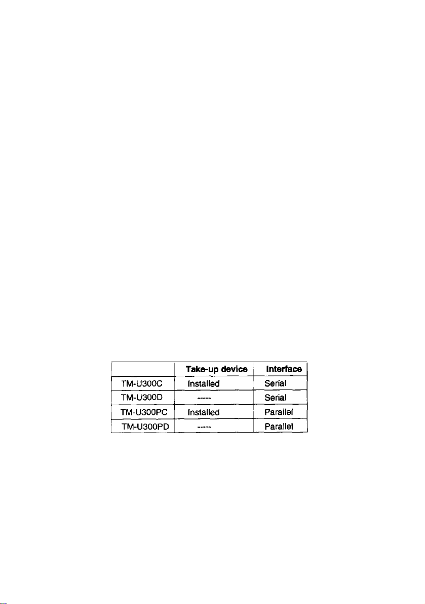
l Roll paper take-up device (for the TM-U300C and the TM-U300PC)
The table below describes the differences between the TM-U300C/U300D and
TM-U300PC/U300PD printers.
®
standard
Please be sure to read the instructions in this manual carefully before using your
new Epson printer.
ii
Page 6

CONTENTS
Chapter1 UnpackingthePrinter
1-1
Checking the Contentsof the
1-2
Choosing aPlacefor thePrinter..
1-3 RemovingtheTransportation
1-4
PartNamesandFunctions
Chapter2ConnectingtheCables
2-1
Connecting the AC Adapter to the
2-2 Connecting the Host Computer to the
Chapter3InstallingthePrinterParts
3-1
Installing theRibbonCassette......................................................................
3-2 Installing thePaperRoll..
3-3 Adjusting the Paper Near-End Detector
3-4
Inserting a Cut Sheet (Validation
Chapter4Settingthe
Chapter5TheSelfTest
DIP
. . . . . . . . . . . . . . . . . . . . . . . . . . . . . . . . . . . . . . . . . . . . . . . . . . . . . . . . . . . . . . . . . . . . . . . . . . . . . . . . . . . .
Chapter6RemovingJammedPaper
6-1
Removing Jammed Paper. .........................................................................
Appendix
.................................................................................................................
...........................................................................
PrinterBox ...................................................
.................................................................
Damper.........................................................
............................................................................
..........................................................................
Printer ................................................
Printer ..........................................
....................................................................
.............................................................................
Location ........................................
.
..................................................
.
Paper)
Switches
.....................................................................
...................................................................
1
1
2
2
3
5
5
6
8
8
11
19
21
23
26
27
27
28
AppendixA.S
pecifications
.............................................................................
28
Page 7
Chapter 1 Unpacking the Printer
1-1
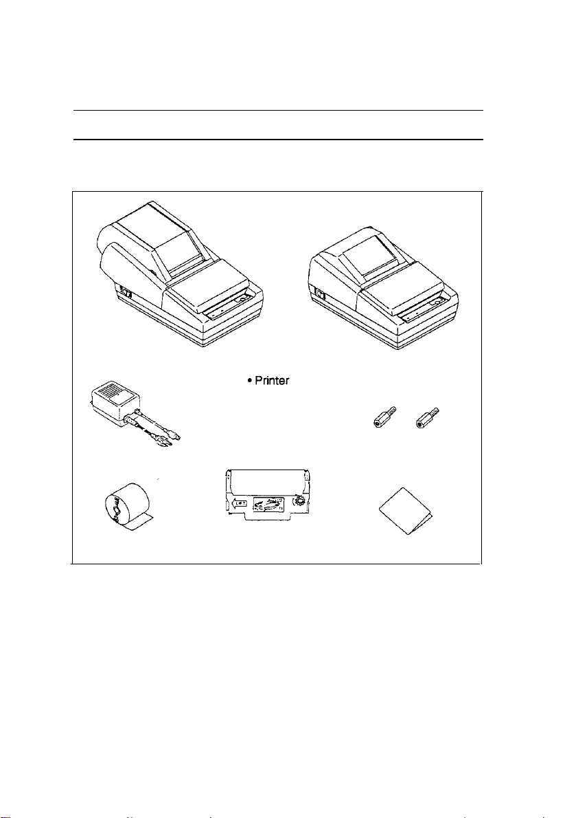
The illustration below shows the items included for the standard specification printer.
Checking the Contents of the Printer Box
TM-U300C/U300PC
l AC adapter (*1)
n 7
TM-U300D/U300PD
l Hexagonal lock
screws (2 pcs) (*2)
l Roll paper l Ribbon cassette l Operator’s Manual
(*1) One of eight types of AC adapters may be included with your printer. Refer to
Appendix A, Specifications for information on your AC adapter’s input voltage,
dimensions, and weight.
(*2) Hexagonal lock screws are provided only if the printer has a serial interface.
See note on page 7 for more information about these screws.
Make sure you have all the items shown above. If any items are damaged or missing, please contact your dealer for assistance.
Keep the original box and packing materials in case you need to transport or store
the printer later.
1
Page 8
1-2
n Avoid locations in direct sunlight or subject to excessive heat (such as near
■
n
n
W
Choosing a Place for the Printer
heaters).
Avoid using or storing the printer in places subject to excessive moisture.
Do not use or store the printer in a dusty or dirty area.
Choose a stable, horizontal surface for the printer. Avoid places subject to
intense vibration or shock.
Make sure there is enough space around the printer so that it can be used easily.
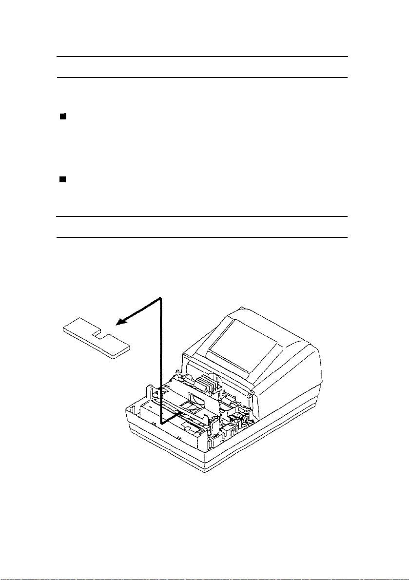
1-3
The transportation damper must be removed before turning on the printer.
Open the printer cover and remove the damper as shown below.
Removing the Transportation Damper
2
Page 9
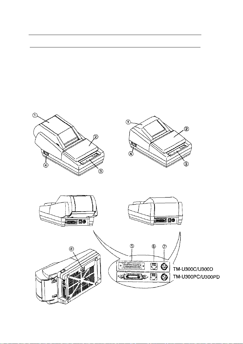
1-4 Part Names and Functions
n
Part names
➀ Take-up device cover (TM-U300C/U300PC)
Roll paper cover (TM-U300D/U300PD)
➁ Printer cover ➆ Power connector
➂ Control panel ➇ DIP switches
➃ Power switch
TM-U300C/U300PC TM-U300D/U300PD
➄ Interface connector
➅ Drawer kick-out connector
3
Page 10
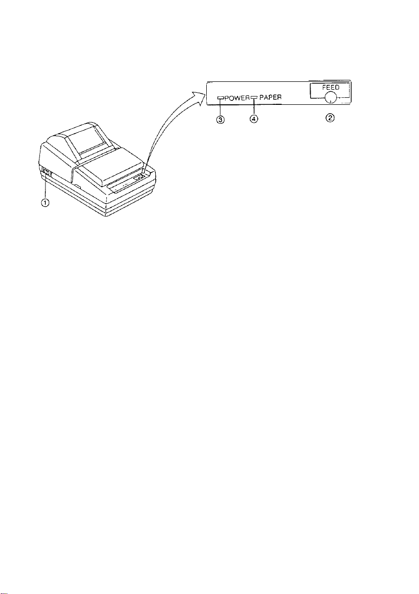
n
Functions
b
Switches and Buttons
➀
POWER Switch
The POWER switch is used to turn the printer on and off.
➁
FEED Button
The FEED button is used to feed roll paper. The line feed amount is set by the
printer commands ESC 2 and ESC 3.
I
0
Control Panel Lights (LEDs)
➂
POWER LED (green)
The POWER LED is on when the printer is turned on and off when the printer is
turned off.
➃
PAPER LED (red)
Normally the PAPER LED is off.
The PAPER LED is on when the paper roll is nearly finished or completely
finished or the paper roll is not installed.
The PAPER LED blinks when an error occurs, when validation paper must be
inserted or removed, when the self test enters the printing standby state, or when
printing has stopped due to exceeding the allowable print duty cycle.
4
Page 11
Chapter 2 Connecting the Cables
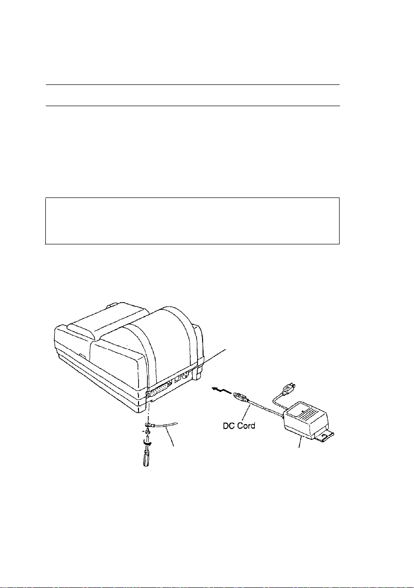
2-1
➀ Make sure the printer is turned off. It is off when the O side of the switch is
➁ Check the label on the AC adapter to make sure the voltage required by the AC
➂ Plug the DC cord connector into the printer’s power connector with the arrow
Connecting the AC Adapter to the Printer
Follow these steps to connect the AC adapter to the printer:
pressed down.
adapter matches that of your electrical outlet.
CAUTIONS:
l To avoid damage to the AC adapter and the printer,
rect operation of the printer, do not plug in the power cord, if the rated
voltage of the AC adapter and your outlet voltage do not match.
mark facing upward.(You can remove the DC cord by grasping the connector
firmly at the arrow mark and pulling it straight out.)
Power Connector
or to avoid an incor-
Frame Ground Screw -----
Frame ground cable
➃ Ground the printer by connecting a frame ground cable (*1) to the printer with
the frame ground screw located on the bottom of the printer.
(*1) This cable is not enclosed. Please obtain the appropriate cable for your
system.
➄ Plug the AC adapter power cord into the wall outlet.
5
AC Adapter
Page 12
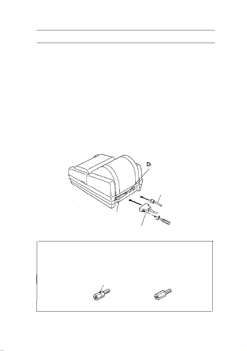
2-2
Connect the host ECR (host computer) to the printer using an interface cable that
matches the specifications of the printer and the host ECR (host computer).
Be sure to use a drawer that matches the printer’s specifications.
■
Connect the interface cable as follows:
➀ Turn off the printer and the host ECR (host computer).
➁ Plug the serial interface cable connector into the printer’s interface connector:
➂ Plug the drawer kick-out cable connector into the printer’s drawer kick-out con-
Connecting the Host Computer to the Printer
Connecting the host computer to the TM-U300C/U300D
then tighten the screws on both sides of the connector.
nector. (You can remove the drawer kick-out cable by pressing in the
connector’s clip and pulling out the connector.)
rawer Kick-out Connector
Drawer Kick-out Cable
Interface Connector
Serial Interface Cable
NOTE:
l Your printer comes with inch-type hexagonal lock screws installed. If you
plan to use an interface cable that requires millimeter-type lock screws, replace the inch-type screws with the enclosed millimeter-type screws using
a hex screwdriver (5 mm). To distinguish the two types of screws, see the
I
figure below.
Notch (one or more line)
Inch-type
Millimeter-type
6
Page 13
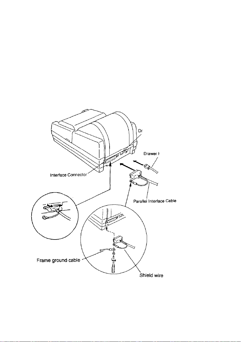
n
Connecting the host computer to the TM-U300PC/U300PD
Connect the interface cable as follows:
➀ Turn off the printer and the host ECR (host computer).
➁ Plug the parallel interface cable connector into the printer’s interface connector.
➂ Squeeze the wire clips together until they lock in place on both sides of the
connector.
➃ Secure the frame ground cable and the shield wire of the parallel interface
cable with the frame ground screw on the bottom of the printer.
➄ Plug the drawer kick-out cable connector into the printer's drawer kick-out con-
nector. (You can remove the drawer kick-out cable by pressing in the
connector’s clip and pulling out the connector.)
rawer Kick-out Connector
Kick-out Cable
7
Page 14
Chapter 3 Installing the Printer Parts
3-1
Installing the Ribbon Cassette
■
lnstalling the ribbon cassette
Use Epson ribbon cassette ERC-34 (B/R).
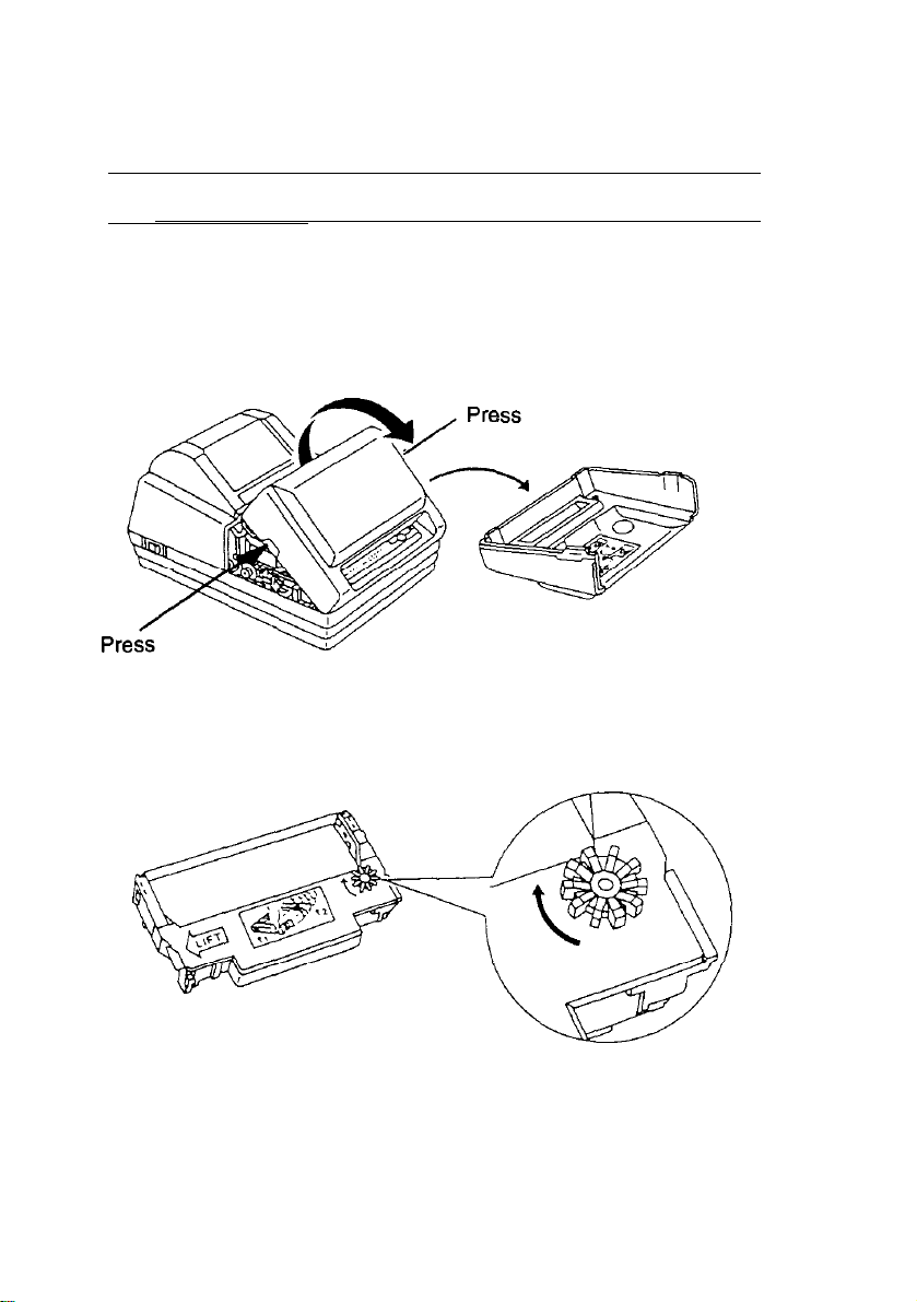
Follow these steps to install the ribbon cassette:
➀ Open the printer cover while lightly pressing the printer cover as shown below.
➁ Turn the ribbon-tightening knob in the direction of the arrow to take up any slack
in the ribbon.
8
Page 15

➂ Fit the ribbon between the print head unit and the ribbon mask. Then push the
cassette firmly into position.
Ribbon mask
➃ Turn the ribbon-tightening knob five or six times in the direction of the arrow to
feed the ribbon smoothly into place between the print head unit and the ribbon
mask.
l Check that the ribbon is not twisted or creased.
CAUTION:
l Do not turn the ribbon-tightening knob in the reverse direction.
➄ Close theprinter
Page 16

n
Replacing the ribbon cassette
Use Epson ribbon cassette ERC-34 (B/R).
➀ Open the printer cover while lightly pressing the printer cover as shown below.
➁ To remove the ribbon cassette, grasp the tab on the left side and lift the left side
out first.
➂ To install a new ribbon cassette, follow steps ➁ through ➄ in the previous
section, Installing
the ribbon cassette.
1O
Page 17

3-2 Installing the Paper Roll
n
Installing the paper roll in the TM-U300C/U300PC
Be sure to use roll paper that matches the printer’s specifications. See Appendix
A, Specifications.
➀ Using scissors, cut the leading edge of the roll paper so that it is perpendicular
to the paper feed direction.
Correct
➁ Open the take-up device cover and remove the take-up spool from the printer.
➂ Load the paper roll while lightly pressing the left paper roll holder outward. Re-
lease the holder after fitting the roll paper core onto the holder. Make sure the
paper roll turns freely and be sure to load the paper roll so that it rotates in the
correct direction.
Incorrect
Incorrect
Correct
11
Page 18

➃
Turn on the printer. The POWER LED goes on.
➄ While leaving some slack in the paper roll, insert the end of the roll paper
straight into the paper inlet. The printer automatically feeds the roll paper into
the printer (semi-automatic loading).
➅
Press the FEED button to continue feeding the paper until it extends about 20
cm (8 inches) beyond tear-off edge.
➆
Remove the side board of the take-up spool and insert the end of the roll paper
(or journal paper when using 2- or 3-ply paper) into the groove on the take-up
spool. Wrap the paper around the spool two or three times and then replace the
side board of the take-up spool.
12
Page 19

➇
Install the take-up spool in the printer. Make sure that the gear
spool aligns with the gear on the printer.
➈
Close the take-up device cover.
➉
Tear off any extra paper at the tear-off edge by pulling the paper toward you.
on the take-up
CAUTION:
•
The extra paper must be torn off after closing the take-up device cover so
that roll paper comes out correctly from the paper exit.
13
Page 20

n
Installing the paper roll in the TM-U300D/U300PD
Be sure to use roll paper that matches the printer’s specifications. See Appendix
A, Specifications.
➀
Using scissors, cut the leading edge of the roll paper so that it is perpendicular
to the paper feed direction.
L
Incorrect
➁
Open the roll paper cover.
14
Page 21

➂
Load the roll paper while lightly pressing the paper roll holder outward. Release
the holder after fitting the paper core onto the holder.
turns freely and be sure to load the paper roll so it rotates in the correct direction.
➃
Turn on the printer. The POWER LED goes on.
Make sure the paper roll
Correct
Incorrect
➄ While leaving some slack in the paper roll, Insert the end of the roll paper
straight into the paper inlet. The printer automatically feeds the roll paper into
the printer (semi-automatic loading).
Press the FEED button to continue feeding the paper if insufficient paper is fed
by the semi-automatic loading.
15
Page 22

➅ Close the roll paper cover.
➆ Tear off any extra paper at the tear-off edge by pulling the paper toward you.
CAUTION:
l
The extra paper must be torn off after closing the roll paper cover so that
roll paper comes out correctly from the paper exit.
16
Page 23

■
Replacing the roll paper for TM-U300C/U300PC
Be sure to use roll paper that matches the printer’s specifications. See Appendix
A, Specifications.
➀
Open the take-up device cover.
➁
Remove the take-up spool from the printer. (If it is necessary, cut the paper go-
ing to the take-up spool, using the tear-off edge.) Then remove the roll paper
core.
If there is roll paper remaining, cut the paper straight across using scissors at
the place shown in illustration below.
➂
While pressing the FEED switch, remove the remaining roll paper in the printer
by pulling the paper lightly out in the direction of the arrow.
Cut here if there is paper remaini
➃
To install a new paper roll, see Installing the paper roll in the TM-U300C/U300PC, on
page 11.
17
Page 24

■
Replacing the paper roll in the TM-U300D/U300PD
Be sure to use roll paper that matches the printer's specifications. See Appendix
A, Specifications.
➀
Open the roll paper cover.
➁ Remove the roll paper core. If there is roll paper remaining, cut the paper
straight across using scissors at the place shown in illustration below.
➂
While pressing the FEED button, remove the remaining roll paper in the printer
by pulling the paper lightly out in the direction of the arrow.
Cut here if there is paper remainin
➃
To install a new paper roll, see Installing the paper roll in the TM-U300D/U300PD, on
page 14.
Page 25

3-3
■
When the paper near-end detector senses that the paper is almost out, the printer
turns on the PAPER LED. The PAPER LED also turns on when the paper is completely out or paper roll is not installed.
■
Because the paper roll core size differs depending on the paper roll, you may
need to adjust the paper near-end detector location.
➀ Make sure the paper core inside diameter is 10.5 to 12.5 mm (0.41 to
➁
Adjusting the Paper Near-End Detector Location
The paper near-end detector
Adjusting the paper near-end detector
0.49")
Determine the paper near-end detecting point on your roll paper and measure
diameter A as shown below.
➂
Find the corresponding adjustment position number from the table below.
Table 3-1. Adjustment Position Number
Diameter A
Adjustment position
number
19
Page 26
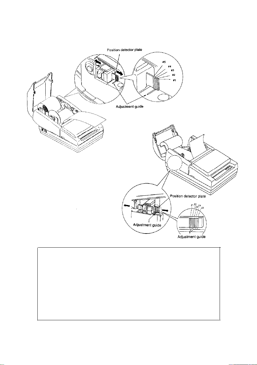
➃
Referring to the illustration below, set the position detector plate to the appropri-
ate position according to the adjustment position number from the table above.
TM-U300C/U300PC
TM-U300D/U300PD
NOTES:
1. Since the adjustment values in the Table 3-1 are calculated value, there may
be some variations depending on the printer.
2. If roll paper with a red end mark at the paper end is used, this mark may
cause the paper to stick together.If this occurs, the paper near-end detector
may operate incorrectly.
3. Be sure that the detecting lever operates smoothly after you finish the
adjustment.
4. If the roll paper becomes loose due to the paper quality, the paper near-end
detector may operate incorrectly.
20
Page 27

3-4 Inserting a Cut Sheet (Validation Paper)
Be sure to use a validation paper that matches the printer’s specifications. Refer
to Appendix A, Specifications.
➀
Check that the paper is not wrinkled.
Using creased or wrinkled paper may
cause a paper jam.
➁
Check that the paper roll is already installed.
If not, install it first.
CAUTION:
l
Printing with no roll paper installed in the printer may cause damage
to the print head pin.
➂
After checking that no validation paper is inserted, turn on the power switch.
The POWER LED light goes on.
➃ Using printer control command, select validation paper mode. The PAPER
LED begins blinking.
➄
Insert the paper straight into the printer using the guide marked with an A in the
following illustration.
CAUTIONS:
l When printing on copy sheets, make sure the glued (fixed) edge is
positioned as shown in the illustration above.
l
After you insert validation paper, do not move the paper. Moving the paper
may cause the paper to slip.
21
Page 28
n
Notes on printing on validation paper
l
The printer can print only one line on validation paper. Printing is performed by
the print commands, but the paper is not fed.
Therefore, double-height printing cannot be performed on validation paper.
l
Printing on the validation paper must be performed when roll paper is loaded.
However, printing is affected by the total thickness of the paper.
l
The validation paper should be flat, with no curls, folds (especially no curls or
folds at the edges), wrinkles, or warps. Otherwise, the paper may rub against
the ribbon and become dirty or the paper could catch on the ribbon.
l Select multi-ply paper carefully because the gluing conditions (glue quality,
gluing method, glued length etc.) and the position of the glued area affect paper
insertion; insert the validation paper so that the glued position is on the left or top
edge of the paper as seen from the front.
l
Insert paper from the top as shown in the following figure.
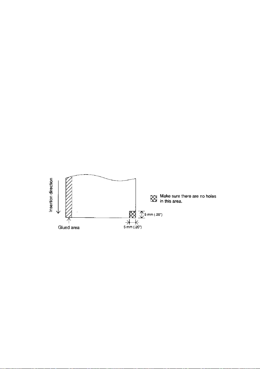
l
When the optional validation detector is installed, do not use validation paper
with holes (e.g., sprocket holes) in the area shown below or the paper detector
does not work correctly.
Validation paper
22
Page 29

Chapter 4 Setting the DIP Switches
n
Finding the DIP switches
As shown in the illustration below, the DIP switches are located on the bottom of
the printer. The DIP switches are used to set the printer to perform various functions
l
The TM-U300C/U300D DIP switches are numbered SW-1 to SW-10 and the
TM-U300PC/U300PD DIP switches are numbered SW-1 to SW-8, from left to right
as shown in figure below.
l
The tables on the following pages describes the DIP switch functions.
■
Setting the DIP switches
Follow these steps when changing DIP switch settings:
➀
Turn the printer power switch off.
➁
Flip the DIP switches using tweezers or another narrow-ended tool.
Switches are on when up and off when down in the figure below.
DIP Switches
TM-U300PC/U300PD
piJ@g]
➂
The new setting takes effect when you turn on the printer.
NOTES:
l
Always change DIP switch settings when the printer is turned off.
l
Changes made with the power on have no effect until you turn the printer
off and then on again.
23
Page 30

n
TM-U300C/U300D DIP Switch Functions
Table 4-1. TM-U300C/U300D DIP Switch Functions
Baud rate selection
Refer to Table 4-2.
(*) Do not change the settings of DIP switches 9 and 10 on the TM-U300C/U300D
Table 4-2. Baud Rate Selection
24
Page 31

n
TM-U300PC/U300PD DIP Switch Functions
Table 4-3. TM-U300PC/U300PD DIP Switch Functions
(* )
Do not change the settings of DIP switches 3 through 6 on the
TM-U300PC/U300PD.
25
Page 32

Chapter 5 The Self Test
■
The purpose of the self test
The self test checks whether the printer has any problems.
function properly, contact your dealer. The self test checks the following:
l
l
Control circuit functions
l
Printer mechanism
l
Print quality l Presence or absence of a validation
Control ROM version
l
DIP switch settings
detector
n
Running the self test
➀ Make sure the ribbon cassette and paper roll have been installed properly.
Make sure the printer cover and the take-up device cover or the roll paper cover
are closed properly.
➁
Turn on the power while holding down the FEED button. The self test begins.
➂
First the self test prints the current printer status, which provides the following
information:
l
Control ROM version
➃
After printing the current
l
DIP switch settings
printer status, it prints
“Self-test printing. Please
press FEED switch”. The
PAPER LED blinks and
the printer enters the test
printing standby state.
Press the FEED button
to restart test printing.
➄ After the printer com-
pletes a certain number
of lines, it prints “
* * *
completed * * * ”, and
stops printing automatically.
*
The printer goes off-line
during and after self-test
printing. Turn the power
off and on again to put
the printer on-line before
transmitting data from
the host computer.
TM-U300C/U300D
If the printer does not
TM-U300PC/U300PD
Self-test Printing Sample
26
Page 33

Chapter 6 Removing Jammed Paper
6-1 Removing Jammed Paper
Turn the paper-feed knob as shown below, and remove any jammed paper.
It may be easier if you cut the roll paper or remove the printer cover.
CAUTION:
Be careful not to touch the tear-off edge.
27
Page 34

Appendix
Appendix A. Specifications
1. Printing Specifications
Printing method:
Head wire arrangement:
Printing directions:
Lines per second:
l
NOTES:
Characters per line:
Characters per inch:
Print color switching: Selectable black or red printing
When printing exceeds the allowable duty cycle, the actual printing
speed may be slower than that listed above.
l
Because switching operations are required for red printing or black/
red printing, their printing speeds are slower than the black printing
speed.
(LPS: Lines Per Second) (CPI: Characters Per Inch)
Serial impact dot matrix
Serial-type, 9-pin
Bi-directional (logic seeking)
Approx. 3.5 LPS
(40 columns, 16 CPI, single color, continuous
printing)
Approx. 5.8 LPS
(20 columns, 16 CPI, single color, continuous
printing)
Refer to Table A-1.
Refer to Table A-1.
2. Character Specifications
Number of characters:
Character structure:
Character size:
Alphanumeric:
Graphics:
International characters: 32
7 x 9 (total number of dots in the horizontal
9 x 9 (total number of dots in the horizontal
Refer to Table A-1.
28
95
128 X 7 tables
direction: 400 half dots)
direction: 400 half dots)
Page 35

Table A-1. Character Size, Characters Per Inch, Characters Per Line
(*1) The 7 x 9 font is the default.
Example
7 x 9 font
Units: mm (inch)
3. Ribbon
Ribbon cassette type:
Color:
Exclusive ribbon cassette ERC-38
Black and Red, Black, Red
Single-color ribbons [Part No.: ERC-34 (P)
(purple) or ERC-34 (B) (black)] and P-color
ribbon [Part No.: ERC-34(B/R) (black and red)]
are also available. When using these ribbons,
the print color selection command (ESC r) must
not be used.
Ribbon life:
(In case of using 2-color type)
Black: Approx. 1,500,000 characters
Approx. 750,000 characters
Red:
[Conditions]
l
Character font:
l
Printing pattern:
7 X 9 font (with descenders)
96 ASCII character rolling pattern, continuous
printing
l
Temperature:
25°C (77°F)
29
Page 36

Ribbon cassette overall dimensions:
Refer to Figure A-1
Figure A-1. ERC-38 Overall Dimensions
4. Roll Paper Supply Device
Supply method:
Near-end detector:
Paper roll holding shaft
Provided inside the printer case
The paper near-end detector location should be
adjusted by the user. Refer to section 3-3, Adjust-
ing the Paper Near-End Detector Location.
l
Roll paper core
inside diameter:
l
Near-end adjustment:
ø 10.5
Adjustable slider
[Units: mm]
to 12.5 mm (0.41" to 0.49")
5. Roll Paper Take-up Device
The TM-U300C and TM-U300PC are equipped with a take-up device. The paper
is automatically taken up by the paper feed motor.
6. Paper
Paper feed method:
Paper feed pitch:
Friction feed
Default 1/6 inch
Can be set in 1/144 inch units by software command.
Paper feed speed:
Approx. 4.17 IPS (25 LPS) (continuous feeding)
(IPS: Inches Per Second)
(LPS: Lines Per Second)
30
Page 37

Paper size:
l
Roll paper
Paper width:
Maximum diameter:
Paper core inside diameter:
➀
Normal paper
Paper thickness:
(single-ply sheet)
Weight:
➁
Pressure sensitive paper
Maximum 1 original + 2 copies
Copy capability is greatly influenced by the ambient temperature. Refer to the table below.
76 mm ± 0.5 mm (2.99" ± 0.02")
ø 83 mm (3.27") (when 2-ply or 3-ply
paper is used)
ø 60 mm (2.36")
(when 1 -ply paper is
used)
ø 10.5 to 12.5 mm
0.06 to 0.085 mm
52.3
g/m2 to 64 g/m
(0.002"
2
(0.41" to 0.49")
to 0.003’)
(45 to 55 kg/1000 sheets/1091 mm x 788 mm)
1
1
Number of copies
Original + 2 copies
Original + I copy
Ambient temperature
Approx. 25°C (77°F)
5° to 40 °C (41° to 104°F)
1
l
Validation paper
Paper type:
Normal paper, pressure-sensitive paper, carbon
copy paper
Paper width and paper length:
Paper thickness:
0.07
Total thickness including roll paper:
0.2 mm (0.008") or less
mm to 0.14 mm
(Weight: 56.2 g/m
31
(0.003" to
2
to 128 g/m2)
0.006")
Page 38

Page 39

10. Environmental Conditions
Temperature:
Operating: 5° to 40°C (41° to 104°F)
For the TM-U300C/U300PC, when the temperature
is 30°C (86°F) or more, the operating humidity is
limited.
Storage:
-10° to 50°C (14 to 122°F) (excluding paper and ribbon)
Humidity:
Operating:
TM-U300C/U300PC: 20% to 80% (non-condensing)
TM-U300D/U300PD: 30% to 85% (non-condensing)
Storage:
TM-U300C/U300PC: 20% to 90%
(non-condensing, excluding paper and ribbon)
TM-U300D/U300PD: 30% to 90%
(non-condensing, excluding paper and ribbon)
33
Page 40

 Loading...