

Page 1

Technical manual
TM-U200D/U200PD
Copied Date 199 , ,
Copied by
English
4005680
Page 2

Confidential
CONFIDENTIALITY AGREEMENT
BY USING THIS DOCUMENT, YOU AGREE TO ABIDE BY THE TERMS OF THIS
AGREEMENT. PLEASE RETURN THIS DOCUMENT IMMEDIATELY IF YOU DO NOT AGREE
TO THESE TERMS.
1. This document contains confidential, prop rietary informat ion of Seiko Epson Corporation or
its affiliates. You must keep such information confidential. If the user is a business entity or
organization, you must limit disclosure to those of your employees, agents and contractors
who have a need to know and who are also bound by obligations of confidentiality.
2. On the earlier of (a) termination of your relationship with Seiko Epson, or (b) Seiko Epson’s
request, you must stop using the confidential information. You must then return or destroy
the information, as directed by Seiko Epson.
3. If a court, arbitrator, government agency or the like orders you to disclose any confidential
information, you must immediately notify Seiko Epson. You agree to give Seiko Epson
reasonable cooperation and assistance in resisting disclosure.
4. You may use confidential information only for the purpose of operating or servicing the
products to which the document relates, unless you obtain the pr ior written consent of Seik o
Epson for some other use.
5. Seiko Epson warrants that it has the right to disclose the confidential information. SEIKO
EPSON MAKES NO OTHER WARRANTIES CONCERNING THE CONFIDENTIAL
INFORMATION OR ANY OTHER INFORMATION IN THE DOCUMENT, INCLUDING
(WITHOUT LIMITATION) ANY WARRANTY OF TITLE OR NON-INFRINGEMENT.
Seiko Epson has no liability for loss or damage arising from or relating to your use of or
reliance on the information on the document.
6. You may not reproduce, store or transmit the confidential information in any form or by any
means (electronic, mechanical, photocopying, recording, or otherwise) without the prior
written permission of Seiko Epson.
7. Your obligations under this Agreement are in addition to any other legal obligations. Seiko
Epson does not waive any right under this Agreement by failing to exercise it. The laws of
Japan apply to this Agreement.
Page 3

CONFIDENTIAL
EPSON
SEIKO EPSON CORPORATION
Printed in Japan E9608130-0000SE
Page 4

CONFIDENTIAL
FCC CLASS A
FCC Compliance Statement
For American Users
This equipment has been tested and found to c omply with th e l imits for a C la ss A digital d evice, pursuant to Part 15 o f
the FCC Rules. These limits are designed to provide reasonable protection against harmful interference when the
equipment is operated in a commercial environment.
This equipment generates, uses, and can radiate radio frequency energy and, if not installed and used in accordance
with the instruction m a nual, may cau se harmful interference to rad io co mmunic ati ons. Oper ati on of t his e quipm ent in
a residential area is likely to cause harmful interference, in which case the user will be required to correct the
interference at his own expense.
WARNING
The connection of a non-shielded printer interface cable to this printer will invalidate the FCC Verification of this
device and may cause interference levels which exceed the limits established by the FCC for this equipment.
You are cautioned that changes or modifications not e xpressly approv ed by the party re sponsible for c ompliance could
void your authority to operate the equipment.
FOR CANADIA N USERS
This digital apparatus does not exceed the Class A limits for radio noise emissions from digital apparatus as set out in
the radio interference regulations of the Canadian Department of Communications.
Le présent appareil numérique n’émet pas de bruits radioélectriques dépassant les limites applicables aux appareils
numériques de Class A prescrites dans le règlement sur le brouillage radioélectrique édicté par le Ministère des
Communications du Canada.
GEREÄUSCHPEGEL
Gemäß der Dritten Verordrung zum Gerät esiche rheit sgecset z (M aschin enlärmi nformat ions - Verordnung -3. GSGV) ist
der arbeitsplatzbezogene Geräusch-Emissionswert kleiner als 70 dB(A) (basierend auf ISO 7779).
TM-U200D/U200PD Technical Manual
Rev. B i
Page 5

CONFIDENTIAL
Introduction
The TM-U200D and TM-U200PD are one-station printers for ECR and POS use which can be used for printing the
results of weighing or measuring.
The main features of the TM-U200D and TM-U200PD printers are the following:
❏ High-speed printing through logic-seeking control
❏ Excellent reliability and long life due to use of two s tepping motor s, one for movin g the carriage and one for paper
feeding
❏ Flexible paper feed setting permits printing in accordance with any user-defined format
❏ Command protocol based on ESC/POS, a widely used standard
❏ Built-in drawer kick-out interface provides capability to drive two drawers
❏ Selectable character fonts (7 x 9, 9 x 9)
❏ Semi-automatic paper loading capability
❏ AC adapter (included) provides compact power supply
❏ Compact and light in weight
❏ Automatic Status Back (ASB) function to automatically send printer status changes.
❏ Two-color printing. Black and red colors are selectable. (2-color Print Version only)
ii Rev. B
Page 6

CONFIDENTIAL
Notes and Cautions
Note:
Notes have important information and useful tips on the operation of your printer.
CAUTION:
Cautions must be observed to avoid damage to you r equipment.
Rev. B iii
Page 7

CONFIDENTIAL
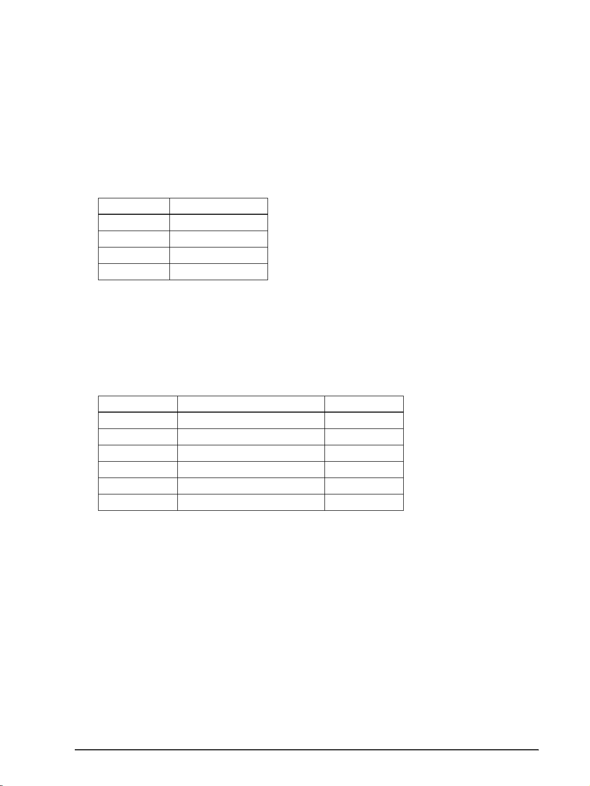
Revision Sheet
Revision Page Altered Item and Contents
Rev. B All Added information of the 2-color Print Version
iv Rev. B
Page 8

CONFIDENTIAL
Chapter 1 Features and General Specifications
Features . . . . . . . . . . . . . . . . . . . . . . . . . . . . . . . . . . . . . . . . . . . . . . . . . . . . . . . . . . . . . . . . . . . . . . . . . . . . . . . . . . . . . . . . . . 1-3
Printing Specifications . . . . . . . . . . . . . . . . . . . . . . . . . . . . . . . . . . . . . . . . . . . . . . . . . . . . . . . . . . . . . . . . . . . . . . . . . 1-3
Character Specifications . . . . . . . . . . . . . . . . . . . . . . . . . . . . . . . . . . . . . . . . . . . . . . . . . . . . . . . . . . . . . . . . . . . . . . . . 1-4
Paper . . . . . . . . . . . . . . . . . . . . . . . . . . . . . . . . . . . . . . . . . . . . . . . . . . . . . . . . . . . . . . . . . . . . . . . . . . . . . . . . . . . . . . . . 1-6
Paper Roll Supply Device . . . . . . . . . . . . . . . . . . . . . . . . . . . . . . . . . . . . . . . . . . . . . . . . . . . . . . . . . . . . . . . . . . . . . . . 1-7
Receive Buffer . . . . . . . . . . . . . . . . . . . . . . . . . . . . . . . . . . . . . . . . . . . . . . . . . . . . . . . . . . . . . . . . . . . . . . . . . . . . . . . . 1-7
Electrical Specifications . . . . . . . . . . . . . . . . . . . . . . . . . . . . . . . . . . . . . . . . . . . . . . . . . . . . . . . . . . . . . . . . . . . . . . . . . 1-8
Ribbon Cassette . . . . . . . . . . . . . . . . . . . . . . . . . . . . . . . . . . . . . . . . . . . . . . . . . . . . . . . . . . . . . . . . . . . . . . . . . . . . . . . 1-8
External Dimensions and Weight . . . . . . . . . . . . . . . . . . . . . . . . . . . . . . . . . . . . . . . . . . . . . . . . . . . . . . . . . . . . . . . . 1-9
Environmental Specifications . . . . . . . . . . . . . . . . . . . . . . . . . . . . . . . . . . . . . . . . . . . . . . . . . . . . . . . . . . . . . . . . . . . 1-9
Reliability . . . . . . . . . . . . . . . . . . . . . . . . . . . . . . . . . . . . . . . . . . . . . . . . . . . . . . . . . . . . . . . . . . . . . . . . . . . . . . . . . . . . 1-10
Safety and EMI Standards Applied . . . . . . . . . . . . . . . . . . . . . . . . . . . . . . . . . . . . . . . . . . . . . . . . . . . . . . . . . . . . . . 1-10
Printer Installation Stance . . . . . . . . . . . . . . . . . . . . . . . . . . . . . . . . . . . . . . . . . . . . . . . . . . . . . . . . . . . . . . . . . . . . . . 1-10
Hardware Configuration . . . . . . . . . . . . . . . . . . . . . . . . . . . . . . . . . . . . . . . . . . . . . . . . . . . . . . . . . . . . . . . . . . . . . . . . . . . 1-11
Main Unit Specifications . . . . . . . . . . . . . . . . . . . . . . . . . . . . . . . . . . . . . . . . . . . . . . . . . . . . . . . . . . . . . . . . . . . . . . . . . . . . 1-12
Motor, Paper Feed . . . . . . . . . . . . . . . . . . . . . . . . . . . . . . . . . . . . . . . . . . . . . . . . . . . . . . . . . . . . . . . . . . . . . . . . . . . . . 1-12
Motor, Carriage . . . . . . . . . . . . . . . . . . . . . . . . . . . . . . . . . . . . . . . . . . . . . . . . . . . . . . . . . . . . . . . . . . . . . . . . . . . . . . . 1-12
Print Head Unit . . . . . . . . . . . . . . . . . . . . . . . . . . . . . . . . . . . . . . . . . . . . . . . . . . . . . . . . . . . . . . . . . . . . . . . . . . . . . . . 1-12
Detector Sub-ass’y . . . . . . . . . . . . . . . . . . . . . . . . . . . . . . . . . . . . . . . . . . . . . . . . . . . . . . . . . . . . . . . . . . . . . . . . . . . . . 1-12
Paper Detector Switch Sub-ass’y . . . . . . . . . . . . . . . . . . . . . . . . . . . . . . . . . . . . . . . . . . . . . . . . . . . . . . . . . . . . . . . . . 1-13
Near-end Detector (N.E.-U200); (Optional) . . . . . . . . . . . . . . . . . . . . . . . . . . . . . . . . . . . . . . . . . . . . . . . . . . . . . . . . 1-13
Connectors . . . . . . . . . . . . . . . . . . . . . . . . . . . . . . . . . . . . . . . . . . . . . . . . . . . . . . . . . . . . . . . . . . . . . . . . . . . . . . . . . . . . . . . 1-13
Interface Connector . . . . . . . . . . . . . . . . . . . . . . . . . . . . . . . . . . . . . . . . . . . . . . . . . . . . . . . . . . . . . . . . . . . . . . . . . . . . 1-13
Power Supply Connector . . . . . . . . . . . . . . . . . . . . . . . . . . . . . . . . . . . . . . . . . . . . . . . . . . . . . . . . . . . . . . . . . . . . . . . 1-14
Drawer Kick-Out Connector . . . . . . . . . . . . . . . . . . . . . . . . . . . . . . . . . . . . . . . . . . . . . . . . . . . . . . . . . . . . . . . . . . . . 1-14
Interface . . . . . . . . . . . . . . . . . . . . . . . . . . . . . . . . . . . . . . . . . . . . . . . . . . . . . . . . . . . . . . . . . . . . . . . . . . . . . . . . . . . . . . . . . . 1-16
RS-232 Serial Interface . . . . . . . . . . . . . . . . . . . . . . . . . . . . . . . . . . . . . . . . . . . . . . . . . . . . . . . . . . . . . . . . . . . . . . . . . . 1-16
Interface Connector Pin Assignments . . . . . . . . . . . . . . . . . . . . . . . . . . . . . . . . . . . . . . . . . . . . . . . . . . . . . . . . . . . . 1-17
RS-485 Serial Interface (option) . . . . . . . . . . . . . . . . . . . . . . . . . . . . . . . . . . . . . . . . . . . . . . . . . . . . . . . . . . . . . . . . . . 1-19
IEEE 1284 Parallel Interface . . . . . . . . . . . . . . . . . . . . . . . . . . . . . . . . . . . . . . . . . . . . . . . . . . . . . . . . . . . . . . . . . . . . . 1-19
Reverse Mode (Data Transmission from Printer to Host) . . . . . . . . . . . . . . . . . . . . . . . . . . . . . . . . . . . . . . . . . . . . 1-19
Interface Connector Pin Assignments . . . . . . . . . . . . . . . . . . . . . . . . . . . . . . . . . . . . . . . . . . . . . . . . . . . . . . . . . . . . 1-21
Buttons and Switches . . . . . . . . . . . . . . . . . . . . . . . . . . . . . . . . . . . . . . . . . . . . . . . . . . . . . . . . . . . . . . . . . . . . . . . . . . . . . . 1-24
Power Switch . . . . . . . . . . . . . . . . . . . . . . . . . . . . . . . . . . . . . . . . . . . . . . . . . . . . . . . . . . . . . . . . . . . . . . . . . . . . . . . . . 1-24
Panel Button . . . . . . . . . . . . . . . . . . . . . . . . . . . . . . . . . . . . . . . . . . . . . . . . . . . . . . . . . . . . . . . . . . . . . . . . . . . . . . . . . . 1-24
DIP Switches . . . . . . . . . . . . . . . . . . . . . . . . . . . . . . . . . . . . . . . . . . . . . . . . . . . . . . . . . . . . . . . . . . . . . . . . . . . . . . . . . . 1-25
Panel LEDs . . . . . . . . . . . . . . . . . . . . . . . . . . . . . . . . . . . . . . . . . . . . . . . . . . . . . . . . . . . . . . . . . . . . . . . . . . . . . . . . . . . 1-27
Self-test . . . . . . . . . . . . . . . . . . . . . . . . . . . . . . . . . . . . . . . . . . . . . . . . . . . . . . . . . . . . . . . . . . . . . . . . . . . . . . . . . . . . . . . . . . 1-27
Performing the Self Test . . . . . . . . . . . . . . . . . . . . . . . . . . . . . . . . . . . . . . . . . . . . . . . . . . . . . . . . . . . . . . . . . . . . . . . . 1-27
Error Processing . . . . . . . . . . . . . . . . . . . . . . . . . . . . . . . . . . . . . . . . . . . . . . . . . . . . . . . . . . . . . . . . . . . . . . . . . . . . . . . . . . . 1-28
Printer Operation When an Error Occurs . . . . . . . . . . . . . . . . . . . . . . . . . . . . . . . . . . . . . . . . . . . . . . . . . . . . . . . . . 1-28
Data Receive Error . . . . . . . . . . . . . . . . . . . . . . . . . . . . . . . . . . . . . . . . . . . . . . . . . . . . . . . . . . . . . . . . . . . . . . . . . . . . . 1-28
Buffer Full Printing . . . . . . . . . . . . . . . . . . . . . . . . . . . . . . . . . . . . . . . . . . . . . . . . . . . . . . . . . . . . . . . . . . . . . . . . . . . . . . . . 1-28
Detectors and Printing . . . . . . . . . . . . . . . . . . . . . . . . . . . . . . . . . . . . . . . . . . . . . . . . . . . . . . . . . . . . . . . . . . . . . . . . . . . . . 1-28
Hexadecimal Dump . . . . . . . . . . . . . . . . . . . . . . . . . . . . . . . . . . . . . . . . . . . . . . . . . . . . . . . . . . . . . . . . . . . . . . . . . . . . . . . 1-29
Hexadecimal Dump Function 1-29
Performing a Hexadecimal Dump . . . . . . . . . . . . . . . . . . . . . . . . . . . . . . . . . . . . . . . . . . . . . . . . . . . . . . . . . . . . . . . 1-29
Options . . . . . . . . . . . . . . . . . . . . . . . . . . . . . . . . . . . . . . . . . . . . . . . . . . . . . . . . . . . . . . . . . . . . . . . . . . . . . . . . . . . . . . . . . . 1-29
External Power Supply PS-170 . . . . . . . . . . . . . . . . . . . . . . . . . . . . . . . . . . . . . . . . . . . . . . . . . . . . . . . . . . . . . . . . . . 1-30
TM-U200D/U200PD Technical Manual
Rev. B -1
Page 9

CONFIDENTIAL
Chapter 2 Mechanism Configuration and Operating Principles
Printer Mechanism Operating Principles . . . . . . . . . . . . . . . . . . . . . . . . . . . . . . . . . . . . . . . . . . . . . . . . . . . . . . . . . . . . . . . 2-1
Print mechanism unit . . . . . . . . . . . . . . . . . . . . . . . . . . . . . . . . . . . . . . . . . . . . . . . . . . . . . . . . . . . . . . . . . . . . . . . . . . .2-2
Print head unit movement . . . . . . . . . . . . . . . . . . . . . . . . . . . . . . . . . . . . . . . . . . . . . . . . . . . . . . . . . . . . . . . . . . . . . . .2-3
Wire movement when a single dot is printed . . . . . . . . . . . . . . . . . . . . . . . . . . . . . . . . . . . . . . . . . . . . . . . . . . . . . . . 2-3
Printing a character (9x9 font) . . . . . . . . . . . . . . . . . . . . . . . . . . . . . . . . . . . . . . . . . . . . . . . . . . . . . . . . . . . . . . . . . . .2-4
Paper Feed Mechanism Unit . . . . . . . . . . . . . . . . . . . . . . . . . . . . . . . . . . . . . . . . . . . . . . . . . . . . . . . . . . . . . . . . . . . . .2-5
Paper loading (semi-automatic loading) . . . . . . . . . . . . . . . . . . . . . . . . . . . . . . . . . . . . . . . . . . . . . . . . . . . . . . . . . . .2-6
Paper feeding . . . . . . . . . . . . . . . . . . . . . . . . . . . . . . . . . . . . . . . . . . . . . . . . . . . . . . . . . . . . . . . . . . . . . . . . . . . . . . . . . .2-6
Ribbon Feed Mechanism Unit . . . . . . . . . . . . . . . . . . . . . . . . . . . . . . . . . . . . . . . . . . . . . . . . . . . . . . . . . . . . . . . . . . . .2-7
Ribbon feeding . . . . . . . . . . . . . . . . . . . . . . . . . . . . . . . . . . . . . . . . . . . . . . . . . . . . . . . . . . . . . . . . . . . . . . . . . . . . . . . . .2-7
Detection Mechanism Unit . . . . . . . . . . . . . . . . . . . . . . . . . . . . . . . . . . . . . . . . . . . . . . . . . . . . . . . . . . . . . . . . . . . . . .2-9
Home position detection mechanism . . . . . . . . . . . . . . . . . . . . . . . . . . . . . . . . . . . . . . . . . . . . . . . . . . . . . . . . . . . . . . 2-9
Paper detection mechanism . . . . . . . . . . . . . . . . . . . . . . . . . . . . . . . . . . . . . . . . . . . . . . . . . . . . . . . . . . . . . . . . . . . . . . 2-10
Near-end detection mechanism (optional) . . . . . . . . . . . . . . . . . . . . . . . . . . . . . . . . . . . . . . . . . . . . . . . . . . . . . . . . . 2-10
Ribbon Switch Mechanism Unit . . . . . . . . . . . . . . . . . . . . . . . . . . . . . . . . . . . . . . . . . . . . . . . . . . . . . . . . . . . . . . . . . . . . . .2-10
Switching from Black to Red . . . . . . . . . . . . . . . . . . . . . . . . . . . . . . . . . . . . . . . . . . . . . . . . . . . . . . . . . . . . . . . . . . . . . 2-11
Releasing from Red to Black . . . . . . . . . . . . . . . . . . . . . . . . . . . . . . . . . . . . . . . . . . . . . . . . . . . . . . . . . . . . . . . . . . . . .2-11
Electrical Circuitry Operating Principles . . . . . . . . . . . . . . . . . . . . . . . . . . . . . . . . . . . . . . . . . . . . . . . . . . . . . . . . . . . . . . . 2-12
Hardware Configuration . . . . . . . . . . . . . . . . . . . . . . . . . . . . . . . . . . . . . . . . . . . . . . . . . . . . . . . . . . . . . . . . . . . . . . . .2-12
Principles of Operation . . . . . . . . . . . . . . . . . . . . . . . . . . . . . . . . . . . . . . . . . . . . . . . . . . . . . . . . . . . . . . . . . . . . . . . . . . . . . .2-16
Power Supply Circuitry . . . . . . . . . . . . . . . . . . . . . . . . . . . . . . . . . . . . . . . . . . . . . . . . . . . . . . . . . . . . . . . . . . . . . . . . .2-16
Control Circuitry . . . . . . . . . . . . . . . . . . . . . . . . . . . . . . . . . . . . . . . . . . . . . . . . . . . . . . . . . . . . . . . . . . . . . . . . . . . . . . .2-17
CPU . . . . . . . . . . . . . . . . . . . . . . . . . . . . . . . . . . . . . . . . . . . . . . . . . . . . . . . . . . . . . . . . . . . . . . . . . . . . . . . . . . . . . . . . . .2-18
Various detector circuits . . . . . . . . . . . . . . . . . . . . . . . . . . . . . . . . . . . . . . . . . . . . . . . . . . . . . . . . . . . . . . . . . . . . . . . . .2-22
Host interface circuit . . . . . . . . . . . . . . . . . . . . . . . . . . . . . . . . . . . . . . . . . . . . . . . . . . . . . . . . . . . . . . . . . . . . . . . . . . . .2-23
Drawer kick-out drive circuit . . . . . . . . . . . . . . . . . . . . . . . . . . . . . . . . . . . . . . . . . . . . . . . . . . . . . . . . . . . . . . . . . . . .2-23
DIP switch read circuit . . . . . . . . . . . . . . . . . . . . . . . . . . . . . . . . . . . . . . . . . . . . . . . . . . . . . . . . . . . . . . . . . . . . . . . . . . 2-24
Printer Mechanism Drive Circuit . . . . . . . . . . . . . . . . . . . . . . . . . . . . . . . . . . . . . . . . . . . . . . . . . . . . . . . . . . . . . . . . . . . . .2-25
Print head drive circuit . . . . . . . . . . . . . . . . . . . . . . . . . . . . . . . . . . . . . . . . . . . . . . . . . . . . . . . . . . . . . . . . . . . . . . . . . .2-25
Chapter 3 Handling and Maintenance
Handling Precautions . . . . . . . . . . . . . . . . . . . . . . . . . . . . . . . . . . . . . . . . . . . . . . . . . . . . . . . . . . . . . . . . . . . . . . . . . . . . . . .3-1
Storage Precautions . . . . . . . . . . . . . . . . . . . . . . . . . . . . . . . . . . . . . . . . . . . . . . . . . . . . . . . . . . . . . . . . . . . . . . . . . . . . .3-1
Use Precautions . . . . . . . . . . . . . . . . . . . . . . . . . . . . . . . . . . . . . . . . . . . . . . . . . . . . . . . . . . . . . . . . . . . . . . . . . . . . . . . .3-1
Paper Handling Precautions . . . . . . . . . . . . . . . . . . . . . . . . . . . . . . . . . . . . . . . . . . . . . . . . . . . . . . . . . . . . . . . . . . . . . .3-1
Ribbon Cassette Handling Precautions . . . . . . . . . . . . . . . . . . . . . . . . . . . . . . . . . . . . . . . . . . . . . . . . . . . . . . . . . . . . .3-2
Replacing the Paper Roll . . . . . . . . . . . . . . . . . . . . . . . . . . . . . . . . . . . . . . . . . . . . . . . . . . . . . . . . . . . . . . . . . . . . . . . . . . . . .3-2
Replacing the Ribbon Cassette . . . . . . . . . . . . . . . . . . . . . . . . . . . . . . . . . . . . . . . . . . . . . . . . . . . . . . . . . . . . . . . . . . . . . . . .3-4
Removing Jammed Paper . . . . . . . . . . . . . . . . . . . . . . . . . . . . . . . . . . . . . . . . . . . . . . . . . . . . . . . . . . . . . . . . . . . . . . . . . . . .3-6
Using the Power switch cover . . . . . . . . . . . . . . . . . . . . . . . . . . . . . . . . . . . . . . . . . . . . . . . . . . . . . . . . . . . . . . . . . . . . . . . .3-8
Maintenance . . . . . . . . . . . . . . . . . . . . . . . . . . . . . . . . . . . . . . . . . . . . . . . . . . . . . . . . . . . . . . . . . . . . . . . . . . . . . . . . . . . . . . .3-8
Periodic Checks . . . . . . . . . . . . . . . . . . . . . . . . . . . . . . . . . . . . . . . . . . . . . . . . . . . . . . . . . . . . . . . . . . . . . . . . . . . . . . . .3-8
Cleaning . . . . . . . . . . . . . . . . . . . . . . . . . . . . . . . . . . . . . . . . . . . . . . . . . . . . . . . . . . . . . . . . . . . . . . . . . . . . . . . . . . . . . . . . . . .3-9
Lubricants . . . . . . . . . . . . . . . . . . . . . . . . . . . . . . . . . . . . . . . . . . . . . . . . . . . . . . . . . . . . . . . . . . . . . . . . . . . . . . . . . . . . . . . . .3-9
Lubrication Standard . . . . . . . . . . . . . . . . . . . . . . . . . . . . . . . . . . . . . . . . . . . . . . . . . . . . . . . . . . . . . . . . . . . . . . . . . . . .3-9
Lubricants . . . . . . . . . . . . . . . . . . . . . . . . . . . . . . . . . . . . . . . . . . . . . . . . . . . . . . . . . . . . . . . . . . . . . . . . . . . . . . . . . . . . .3-9
Lubrication Points . . . . . . . . . . . . . . . . . . . . . . . . . . . . . . . . . . . . . . . . . . . . . . . . . . . . . . . . . . . . . . . . . . . . . . . . . . . . . .3-10
-2 Rev.B
Page 10

CONFIDENTIAL
Chapter 4 Troubleshooting
Self-test . . . . . . . . . . . . . . . . . . . . . . . . . . . . . . . . . . . . . . . . . . . . . . . . . . . . . . . . . . . . . . . . . . . . . . . . . . . . . . . . . . . . . . . . . . . 4-1
Initiating the Self-test . . . . . . . . . . . . . . . . . . . . . . . . . . . . . . . . . . . . . . . . . . . . . . . . . . . . . . . . . . . . . . . . . . . . . . . . . . . 4-1
Self-test Standby . . . . . . . . . . . . . . . . . . . . . . . . . . . . . . . . . . . . . . . . . . . . . . . . . . . . . . . . . . . . . . . . . . . . . . . . . . . . . . . 4-1
Ending the Self-test . . . . . . . . . . . . . . . . . . . . . . . . . . . . . . . . . . . . . . . . . . . . . . . . . . . . . . . . . . . . . . . . . . . . . . . . . . . . . 4-2
Troubleshooting Flowchart . . . . . . . . . . . . . . . . . . . . . . . . . . . . . . . . . . . . . . . . . . . . . . . . . . . . . . . . . . . . . . . . . . . . . . . . . . 4-3
Troubleshooting Tables . . . . . . . . . . . . . . . . . . . . . . . . . . . . . . . . . . . . . . . . . . . . . . . . . . . . . . . . . . . . . . . . . . . . . . . . . . . . . 4-9
Error Types and Countermeasures . . . . . . . . . . . . . . . . . . . . . . . . . . . . . . . . . . . . . . . . . . . . . . . . . . . . . . . . . . . . . . . . . . . . 4-14
Chapter 5 Disassemb ly, Assembly, and Adjustment
Small Part Specifications . . . . . . . . . . . . . . . . . . . . . . . . . . . . . . . . . . . . . . . . . . . . . . . . . . . . . . . . . . . . . . . . . . . . . . . . . . . . . 5-1
Disassembly . . . . . . . . . . . . . . . . . . . . . . . . . . . . . . . . . . . . . . . . . . . . . . . . . . . . . . . . . . . . . . . . . . . . . . . . . . . . . . . . . . . . . . . 5-2
Removing the fuse . . . . . . . . . . . . . . . . . . . . . . . . . . . . . . . . . . . . . . . . . . . . . . . . . . . . . . . . . . . . . . . . . . . . . . . . . . . . . . 5-2
Sub-assembly A . . . . . . . . . . . . . . . . . . . . . . . . . . . . . . . . . . . . . . . . . . . . . . . . . . . . . . . . . . . . . . . . . . . . . . . . . . . . . . . . . . . . 5-3
Frame, paper feed unit ass’y . . . . . . . . . . . . . . . . . . . . . . . . . . . . . . . . . . . . . . . . . . . . . . . . . . . . . . . . . . . . . . . . . . . . . 5-3
Main Assembly 1 . . . . . . . . . . . . . . . . . . . . . . . . . . . . . . . . . . . . . . . . . . . . . . . . . . . . . . . . . . . . . . . . . . . . . . . . . . . . . . . . . . . 5-8
Lever, ribbon switch , Spring, ribbon release , Lever, ribbon release , Gear, ribbon intermediate,
Gear, ribbon transmission , Ribbon take-up ass’y , and Plate, ribbon drive ass’y. . . . . . . . . . . . . . . . . . . . . . . . . 5-8
Main Assembly 2 . . . . . . . . . . . . . . . . . . . . . . . . . . . . . . . . . . . . . . . . . . . . . . . . . . . . . . . . . . . . . . . . . . . . . . . . . . . . . . . . . . . 5-10
Tension plate ass’y . . . . . . . . . . . . . . . . . . . . . . . . . . . . . . . . . . . . . . . . . . . . . . . . . . . . . . . . . . . . . . . . . . . . . . . . . . . . . . 5-10
Main Assembly 3 . . . . . . . . . . . . . . . . . . . . . . . . . . . . . . . . . . . . . . . . . . . . . . . . . . . . . . . . . . . . . . . . . . . . . . . . . . . . . . . . . . . 5-10
Frame, paper feed ass’y . . . . . . . . . . . . . . . . . . . . . . . . . . . . . . . . . . . . . . . . . . . . . . . . . . . . . . . . . . . . . . . . . . . . . . . . . 5-10
Main Assembly 4 . . . . . . . . . . . . . . . . . . . . . . . . . . . . . . . . . . . . . . . . . . . . . . . . . . . . . . . . . . . . . . . . . . . . . . . . . . . . . . . . . . . 5-11
Motor, carriage ass’y . . . . . . . . . . . . . . . . . . . . . . . . . . . . . . . . . . . . . . . . . . . . . . . . . . . . . . . . . . . . . . . . . . . . . . . . . . . . 5-11
Main Assembly 5 . . . . . . . . . . . . . . . . . . . . . . . . . . . . . . . . . . . . . . . . . . . . . . . . . . . . . . . . . . . . . . . . . . . . . . . . . . . . . . . . . . . 5-12
Carriage sub-ass’y . . . . . . . . . . . . . . . . . . . . . . . . . . . . . . . . . . . . . . . . . . . . . . . . . . . . . . . . . . . . . . . . . . . . . . . . . . . . . . 5-12
Main Assembly 6 . . . . . . . . . . . . . . . . . . . . . . . . . . . . . . . . . . . . . . . . . . . . . . . . . . . . . . . . . . . . . . . . . . . . . . . . . . . . . . . . . . . 5-13
Shaft, carriage ass’y . . . . . . . . . . . . . . . . . . . . . . . . . . . . . . . . . . . . . . . . . . . . . . . . . . . . . . . . . . . . . . . . . . . . . . . . . . . . . 5-13
Main Assembly 7 . . . . . . . . . . . . . . . . . . . . . . . . . . . . . . . . . . . . . . . . . . . . . . . . . . . . . . . . . . . . . . . . . . . . . . . . . . . . . . . . . . . 5-14
Shaft holder, adjusting roller . . . . . . . . . . . . . . . . . . . . . . . . . . . . . . . . . . . . . . . . . . . . . . . . . . . . . . . . . . . . . . . . . . . . . 5-14
Main Assembly 8 . . . . . . . . . . . . . . . . . . . . . . . . . . . . . . . . . . . . . . . . . . . . . . . . . . . . . . . . . . . . . . . . . . . . . . . . . . . . . . . . . . . 5-15
Shaft, carriage guide ass’y . . . . . . . . . . . . . . . . . . . . . . . . . . . . . . . . . . . . . . . . . . . . . . . . . . . . . . . . . . . . . . . . . . . . . . . 5-15
Main Assembly 9 . . . . . . . . . . . . . . . . . . . . . . . . . . . . . . . . . . . . . . . . . . . . . . . . . . . . . . . . . . . . . . . . . . . . . . . . . . . . . . . . . . . 5-15
Spring, belt tension ass’y . . . . . . . . . . . . . . . . . . . . . . . . . . . . . . . . . . . . . . . . . . . . . . . . . . . . . . . . . . . . . . . . . . . . . . . . 5-15
Main Assembly 10 . . . . . . . . . . . . . . . . . . . . . . . . . . . . . . . . . . . . . . . . . . . . . . . . . . . . . . . . . . . . . . . . . . . . . . . . . . . . . . . . . . 5-16
Detector sub-ass’y . . . . . . . . . . . . . . . . . . . . . . . . . . . . . . . . . . . . . . . . . . . . . . . . . . . . . . . . . . . . . . . . . . . . . . . . . . . . . . 5-16
Main Assembly 11 . . . . . . . . . . . . . . . . . . . . . . . . . . . . . . . . . . . . . . . . . . . . . . . . . . . . . . . . . . . . . . . . . . . . . . . . . . . . . . . . . . 5-17
Radiating plate, carriage motor . . . . . . . . . . . . . . . . . . . . . . . . . . . . . . . . . . . . . . . . . . . . . . . . . . . . . . . . . . . . . . . . . . . 5-17
Main Assembly 12 . . . . . . . . . . . . . . . . . . . . . . . . . . . . . . . . . . . . . . . . . . . . . . . . . . . . . . . . . . . . . . . . . . . . . . . . . . . . . . . . . . 5-18
FFC, print head ass’y ( Single-color Print Version only) . . . . . . . . . . . . . . . . . . . . . . . . . . . . . . . . . . . . . . . . . . . . . . 5-18
FPC, print head ass’y (2-color Print Version only) . . . . . . . . . . . . . . . . . . . . . . . . . . . . . . . . . . . . . . . . . . . . . . . . . . . 5-19
Main Assembly 13 . . . . . . . . . . . . . . . . . . . . . . . . . . . . . . . . . . . . . . . . . . . . . . . . . . . . . . . . . . . . . . . . . . . . . . . . . . . . . . . . . . 5-20
Print head ground plate and Print head unit (Single-color Print Version only) . . . . . . . . . . . . . . . . . . . . . . . . . . 5-20
Print head unit (2-color Print Version only) . . . . . . . . . . . . . . . . . . . . . . . . . . . . . . . . . . . . . . . . . . . . . . . . . . . . . . . . 5-21
Main Assembly 14 . . . . . . . . . . . . . . . . . . . . . . . . . . . . . . . . . . . . . . . . . . . . . . . . . . . . . . . . . . . . . . . . . . . . . . . . . . . . . . . . . . 5-23
Fame, ribbon knob and Frame, ribbon ass’y (Single-color Print Version only) . . . . . . . . . . . . . . . . . . . . . . . . . . . 5-23
Main assembly 15 . . . . . . . . . . . . . . . . . . . . . . . . . . . . . . . . . . . . . . . . . . . . . . . . . . . . . . . . . . . . . . . . . . . . . . . . . . . . . . . . . . 5-24
Fixing plate, cover, left and Fixing plate, cover, right (2-color Print Version) . . . . . . . . . . . . . . . . . . . . . . . . . . . . 5-24
Main Assembly 16 . . . . . . . . . . . . . . . . . . . . . . . . . . . . . . . . . . . . . . . . . . . . . . . . . . . . . . . . . . . . . . . . . . . . . . . . . . . . . . . . . . 5-25
Earth plate, ribbon frame (2-color Print Version only) . . . . . . . . . . . . . . . . . . . . . . . . . . . . . . . . . . . . . . . . . . . . . . . 5-25
Main Assembly 17 . . . . . . . . . . . . . . . . . . . . . . . . . . . . . . . . . . . . . . . . . . . . . . . . . . . . . . . . . . . . . . . . . . . . . . . . . . . . . . . . . . 5-26
Frame, ribbon ass’y, Spring, ribbon frame and Fixing plate, ribbon frame (2-color Print Version only) . . . . . . 5-26
Main Assembly 18 . . . . . . . . . . . . . . . . . . . . . . . . . . . . . . . . . . . . . . . . . . . . . . . . . . . . . . . . . . . . . . . . . . . . . . . . . . . . . . . . . . 5-27
Thumb-screw and Cover, head (2-color Print Version only) . . . . . . . . . . . . . . . . . . . . . . . . . . . . . . . . . . . . . . . . . . 5-27
Main Assembly 1 (Case Unit) . . . . . . . . . . . . . . . . . . . . . . . . . . . . . . . . . . . . . . . . . . . . . . . . . . . . . . . . . . . . . . . . . . . . . . . . 5-28
TM-U200D/U200PD Technical Manual
Rev. B -3
Page 11

CONFIDENTIAL
Plate, cutter, lower . . . . . . . . . . . . . . . . . . . . . . . . . . . . . . . . . . . . . . . . . . . . . . . . . . . . . . . . . . . . . . . . . . . . . . . . . . . . . . 5-28
Main Assembly 2 (Case Unit) . . . . . . . . . . . . . . . . . . . . . . . . . . . . . . . . . . . . . . . . . . . . . . . . . . . . . . . . . . . . . . . . . . . . . . . . . 5-29
Plate, upper . . . . . . . . . . . . . . . . . . . . . . . . . . . . . . . . . . . . . . . . . . . . . . . . . . . . . . . . . . . . . . . . . . . . . . . . . . . . . . . . . . . . 5-29
Main Assembly 3 (Case Unit) . . . . . . . . . . . . . . . . . . . . . . . . . . . . . . . . . . . . . . . . . . . . . . . . . . . . . . . . . . . . . . . . . . . . . . . . . 5-30
Main circuit board ass’y . . . . . . . . . . . . . . . . . . . . . . . . . . . . . . . . . . . . . . . . . . . . . . . . . . . . . . . . . . . . . . . . . . . . . . . . . 5-30
Main Assembly 4 (Case Unit) . . . . . . . . . . . . . . . . . . . . . . . . . . . . . . . . . . . . . . . . . . . . . . . . . . . . . . . . . . . . . . . . . . . . . . . . . 5-32
Inserting the cables . . . . . . . . . . . . . . . . . . . . . . . . . . . . . . . . . . . . . . . . . . . . . . . . . . . . . . . . . . . . . . . . . . . . . . . . . . . . . . 5-32
Main Assembly 5 (Case Unit) . . . . . . . . . . . . . . . . . . . . . . . . . . . . . . . . . . . . . . . . . . . . . . . . . . . . . . . . . . . . . . . . . . . . . . . . . 5-32
Case, lower . . . . . . . . . . . . . . . . . . . . . . . . . . . . . . . . . . . . . . . . . . . . . . . . . . . . . . . . . . . . . . . . . . . . . . . . . . . . . . . . . . . . 5-32
Main Assembly 6 (Case Unit) . . . . . . . . . . . . . . . . . . . . . . . . . . . . . . . . . . . . . . . . . . . . . . . . . . . . . . . . . . . . . . . . . . . . . . . . . 5-34
Manual cutter . . . . . . . . . . . . . . . . . . . . . . . . . . . . . . . . . . . . . . . . . . . . . . . . . . . . . . . . . . . . . . . . . . . . . . . . . . . . . . . . . . 5-34
Main Assembly 7 (Case Unit) . . . . . . . . . . . . . . . . . . . . . . . . . . . . . . . . . . . . . . . . . . . . . . . . . . . . . . . . . . . . . . . . . . . . . . . . . 5-35
Paper roll receive rollers, Case, upper, Roller, guide and Switch panel . . . . . . . . . . . . . . . . . . . . . . . . . . . . . . . . . 5-35
Main Assembly 8 (Case Unit) . . . . . . . . . . . . . . . . . . . . . . . . . . . . . . . . . . . . . . . . . . . . . . . . . . . . . . . . . . . . . . . . . . . . . . . . . 5-37
Interface circuit board ass’y and Connector plate . . . . . . . . . . . . . . . . . . . . . . . . . . . . . . . . . . . . . . . . . . . . . . . . . . . . 5-37
Main Assembly 9 (Case Unit) . . . . . . . . . . . . . . . . . . . . . . . . . . . . . . . . . . . . . . . . . . . . . . . . . . . . . . . . . . . . . . . . . . . . . . . . . 5-38
Plate, lower, Cover, ROM, and Rubber foot . . . . . . . . . . . . . . . . . . . . . . . . . . . . . . . . . . . . . . . . . . . . . . . . . . . . . . . . . 5-38
Main Assembly 10 (Case Unit) . . . . . . . . . . . . . . . . . . . . . . . . . . . . . . . . . . . . . . . . . . . . . . . . . . . . . . . . . . . . . . . . . . . . . . . . 5-40
Caution seal AB (Single-color Print Version only) . . . . . . . . . . . . . . . . . . . . . . . . . . . . . . . . . . . . . . . . . . . . . . . . . . . 5-40
Main Assembly 11 (Case Unit) . . . . . . . . . . . . . . . . . . . . . . . . . . . . . . . . . . . . . . . . . . . . . . . . . . . . . . . . . . . . . . . . . . . . . . . . 5-41
Cover, main and Hinge ass’y (There are two type printers, which are either with or without the
Hinge ass’y) . . . . . . . . . . . . . . . . . . . . . . . . . . . . . . . . . . . . . . . . . . . . . . . . . . . . . . . . . . . . . . . . . . . . . . . . . . . . . . . . . . . .5-41
Near-end detector ass’y(N.E-U200); (optional) . . . . . . . . . . . . . . . . . . . . . . . . . . . . . . . . . . . . . . . . . . . . . . . . . . . . . .5-43
Adjustment . . . . . . . . . . . . . . . . . . . . . . . . . . . . . . . . . . . . . . . . . . . . . . . . . . . . . . . . . . . . . . . . . . . . . . . . . . . . . . . . . . . . . . . . 5-45
Platen gap adjustment . . . . . . . . . . . . . . . . . . . . . . . . . . . . . . . . . . . . . . . . . . . . . . . . . . . . . . . . . . . . . . . . . . . . . . . . . . .5-45
Appendix
RS-485 Serial Interface . . . . . . . . . . . . . . . . . . . . . . . . . . . . . . . . . . . . . . . . . . . . . . . . . . . . . . . . . . . . . . . . . . . . . . . . . . . . . . . A-1
XON/XOFF Transmit Timing . . . . . . . . . . . . . . . . . . . . . . . . . . . . . . . . . . . . . . . . . . . . . . . . . . . . . . . . . . . . . . . . . . . . A-4
Data Format When Using RS-485 . . . . . . . . . . . . . . . . . . . . . . . . . . . . . . . . . . . . . . . . . . . . . . . . . . . . . . . . . . . . . . . . . A-4
Main Circuit Board A Parts Layout . . . . . . . . . . . . . . . . . . . . . . . . . . . . . . . . . . . . . . . . . . . . . . . . . . . . . . . . . . . . . . . . . . . A-6
Main Circuit Board C Parts Layout . . . . . . . . . . . . . . . . . . . . . . . . . . . . . . . . . . . . . . . . . . . . . . . . . . . . . . . . . . . . . . . . . . . A-7
RS-232 Serial Interface Circuit Board Parts Layout . . . . . . . . . . . . . . . . . . . . . . . . . . . . . . . . . . . . . . . . . . . . . . . . . . . . . . . A-8
IEEE 1284 Parallel Interface Circuit Board Parts Layout . . . . . . . . . . . . . . . . . . . . . . . . . . . . . . . . . . . . . . . . . . . . . . . . . . A-9
RS-485 Serial Interface Circuit Board Parts Layout . . . . . . . . . . . . . . . . . . . . . . . . . . . . . . . . . . . . . . . . . . . . . . . . . . . . . . . A-10
Main Circuit Board C Diagram . . . . . . . . . . . . . . . . . . . . . . . . . . . . . . . . . . . . . . . . . . . . . . . . . . . . . . . . . . . . . . . . . . . . . . . A-12
RS-232 Serial Interface Circuit Board Diagram . . . . . . . . . . . . . . . . . . . . . . . . . . . . . . . . . . . . . . . . . . . . . . . . . . . . . . . . . . A-13
IEEE 1284 Parallel Interface Circuit Board Diagram . . . . . . . . . . . . . . . . . . . . . . . . . . . . . . . . . . . . . . . . . . . . . . . . . . . . . . A-14
RS-485 Serial Interface Circuit Board Diagram . . . . . . . . . . . . . . . . . . . . . . . . . . . . . . . . . . . . . . . . . . . . . . . . . . . . . . . . . . A-15
Printer Mechanism Unit Overall Exploded Diagram (Single-color Print Version) . . . . . . . . . . . . . . . . . . . . . . . . . . . . A-16
Printer Mechanism Unit Overall Exploded Diagram (2-color Print Version) . . . . . . . . . . . . . . . . . . . . . . . . . . . . . . . . . A-17
Case Unit Overall Exploded Diagram (Single-color Print Version) . . . . . . . . . . . . . . . . . . . . . . . . . . . . . . . . . . . . . . . . . A-18
Case Unit Overall Exploded Diagram (2-color Print Version) . . . . . . . . . . . . . . . . . . . . . . . . . . . . . . . . . . . . . . . . . . . . . A-19
Printer Mechanism Unit Lubrication Points Diagram (Single-color Print Version) . . . . . . . . . . . . . . . . . . . . . . . . . . . A-20
Case Unit Lubrication Points Diagram (2-color Print Version) . . . . . . . . . . . . . . . . . . . . . . . . . . . . . . . . . . . . . . . . . . . . . A-21
Case Unit Lubrication Points Diagram . . . . . . . . . . . . . . . . . . . . . . . . . . . . . . . . . . . . . . . . . . . . . . . . . . . . . . . . . . . . . . . . . A-22
-4 Rev.B
Page 12
CONFIDENTIAL
Chapter 1
Features and General Specifications
TM-U200D/U200PD Technical Manual
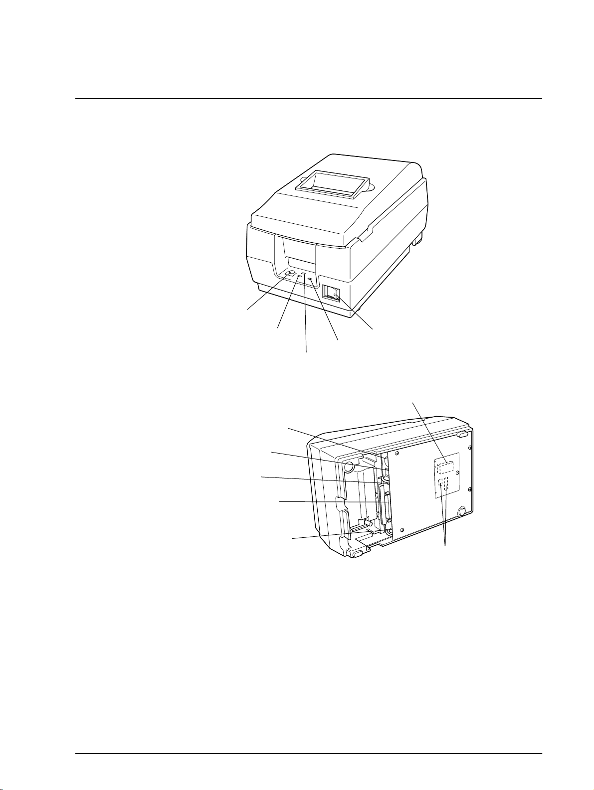
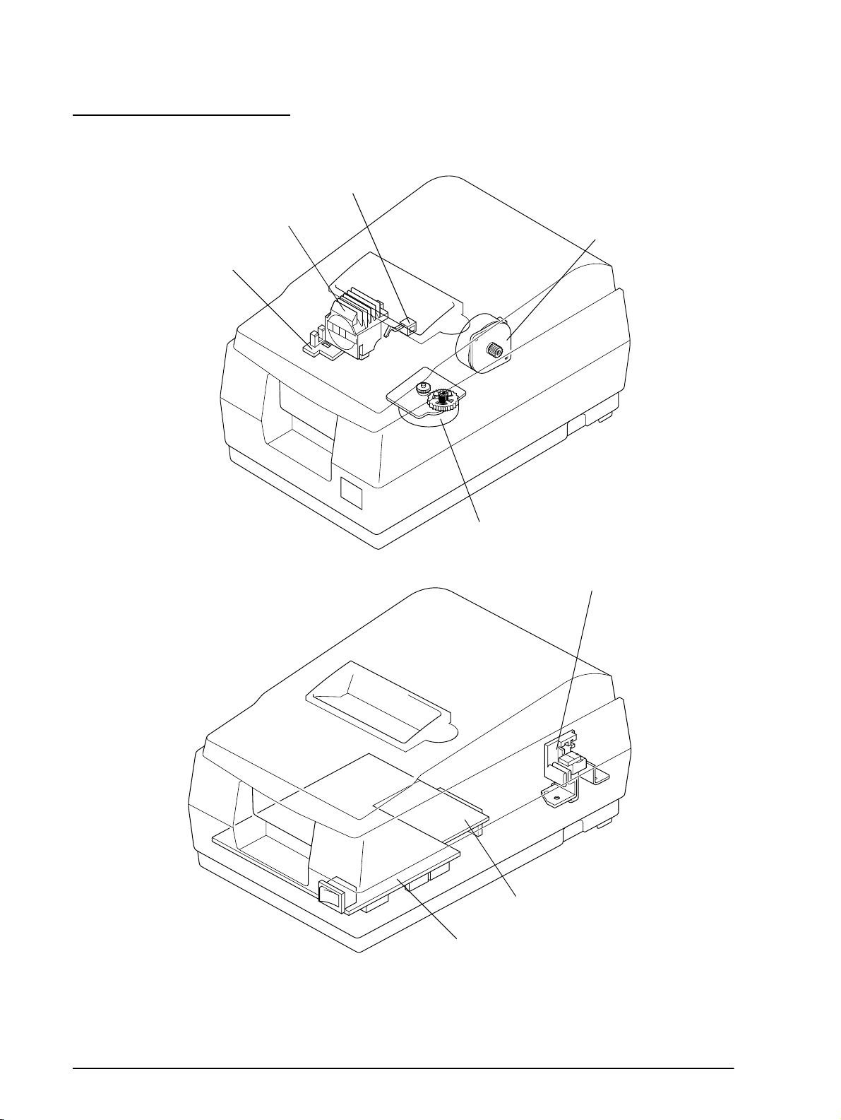
FEED button
ERROR LED
PAPER OUT LED
(PAPER OUT/PRESS FEED)
Power supply connector
Drawer kick-out conne cto r
Frame ground screw
Interface connector
Frame ground screw
Figure 1-1 TM-U200D/U200PD appearance
Power switch
POWER LED
P-ROM
DIP switches
Rev. B Features and General Specifications 1-1
Page 13
CONFIDENTIAL
Features
Printing Specifications
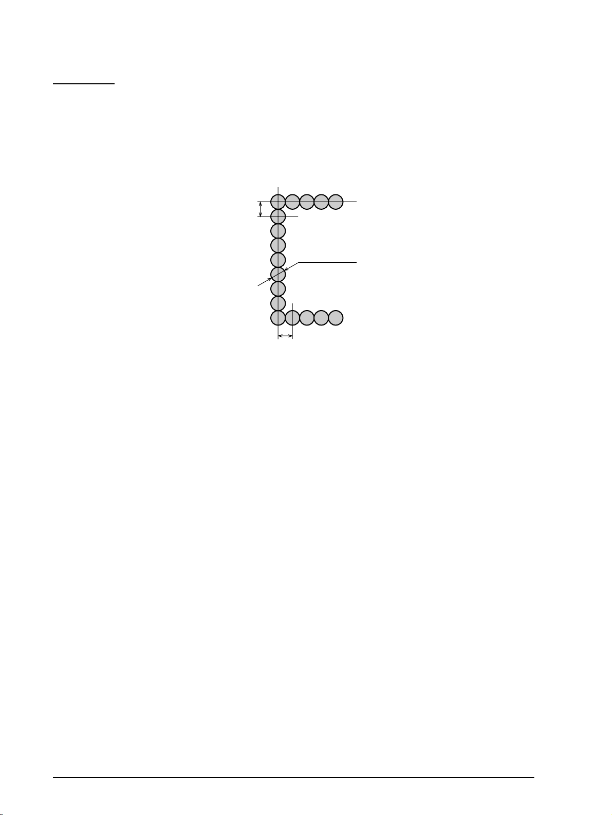
Printing method : Serial impac t dot-matrix
Head wire configuration: 9-pin serial type
0.353 mm
(0.014")
0.29 mm (0.01")
(wire diameter)
0.317 mm (0.012")
Figure 1-2 Dot configuration
Dot pitch: 0.353 mm (1/72")
Dot wire diameter 0.29 mm (0.01")
Printing direction: Bidirectional logic seeking
Printing width: 63.34 mm (2.49")
Line feed: 4.23 mm (1/6"): default setting
Programmable in units of 1/144 inch by using commands.
Paper feed method Friction feed
Paper feed speed: Approximately 4.17 inches/second (25 lines/second) during
continuous paper feeding
Characters per line: See the table in the next page.
Characters per inch: See the table in the next page.
Total dot count (horizontal
direction)
7 x 9 font: 400 half-dot positions per line
9 x 9 font: 400 half-dot positions per line
Printing speed Approximately 3.5 lines/second (40 columns, 16 CPI)
Approximately 6.4 lines/second (16 columns, 16 CPI)
NOTE:If the printing duty ratio is too high, the operation of the print head is stopped by the duty limit. In such
circumstances, the printing speeds shown above cannot be guranteed.
When select red-color or 2-colors(b lack and red) printing, the printing speed g oe s dow n co mpa red with
black-color printing. It is caused by the switching operation in the printer.
1-2 Features and General Specifications Rev.B
Page 14

CONFIDENTIAL
CPI = Characters per inch
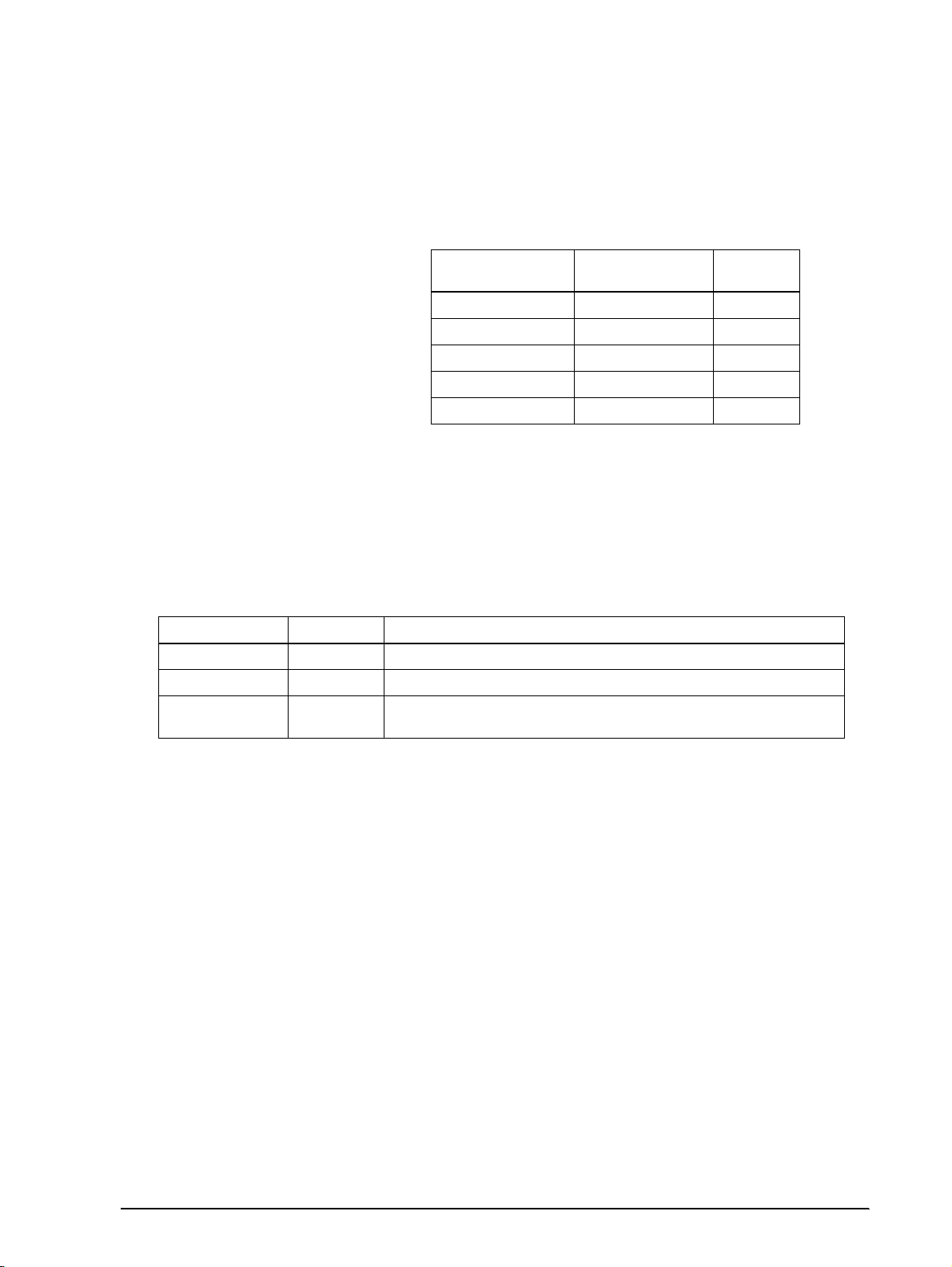
Character dimensions, characters per inch, characters per line
TM-U200D/U200PD Technical Manual
Character Structure
Horizontal x Vert i cal
7 x 9
9 x 9
7 x 9
9 x 9
NOTE: The default font is 7 x 9; the dot spacing between characters is either 3 half dots or 2 half dots depending
on the setting of DIP switch 2-1.
Character
Structure
Character Set
ANK
Graphics
ANK
Graphics
ANK
Graphics
ANK
Graphics
Character
Dimensions
WxH
1.2 x 3.1 mm
(.047 x .122")
1.7 x 3.1 mm
(.070 x .122")
1.6 x 3.1 mm
(.063 x .122")
2.0 x 3.1 mm
(.079 x .122")
1.2 x 3.1 mm
(.047 x .122")
1.6 x 3.1 mm
(.063 x .122")
1.6 x 3.1 mm
(.063 x .122")
1.9 x 3.1 mm
(.075 x .122")
Dot Spacing
Between
Characters
3 half-dots 40 16
04016
3 half-dots 33 13.3
0 33 13.3
2 half-dots 42 17.8
0 42 17.8
2 half-dots 35 14.5
0 35 14.5
Characters Per
Line (CPL)
Characters Per
Inch (CPI)
2color printing. Black and red colors are selectable. (2-color Print Version only)
Character Specifications
Character set:
Character structure:
Alphanumeric: 95
Internat ional: 32
Graphics: 128 x 8 pages
7 x 9 with 400 half-dot positions per line
9 x 9 with 400 half-dot positions per line
Rev. B Features and General Specifications 1-3
Page 15
CONFIDENTIAL
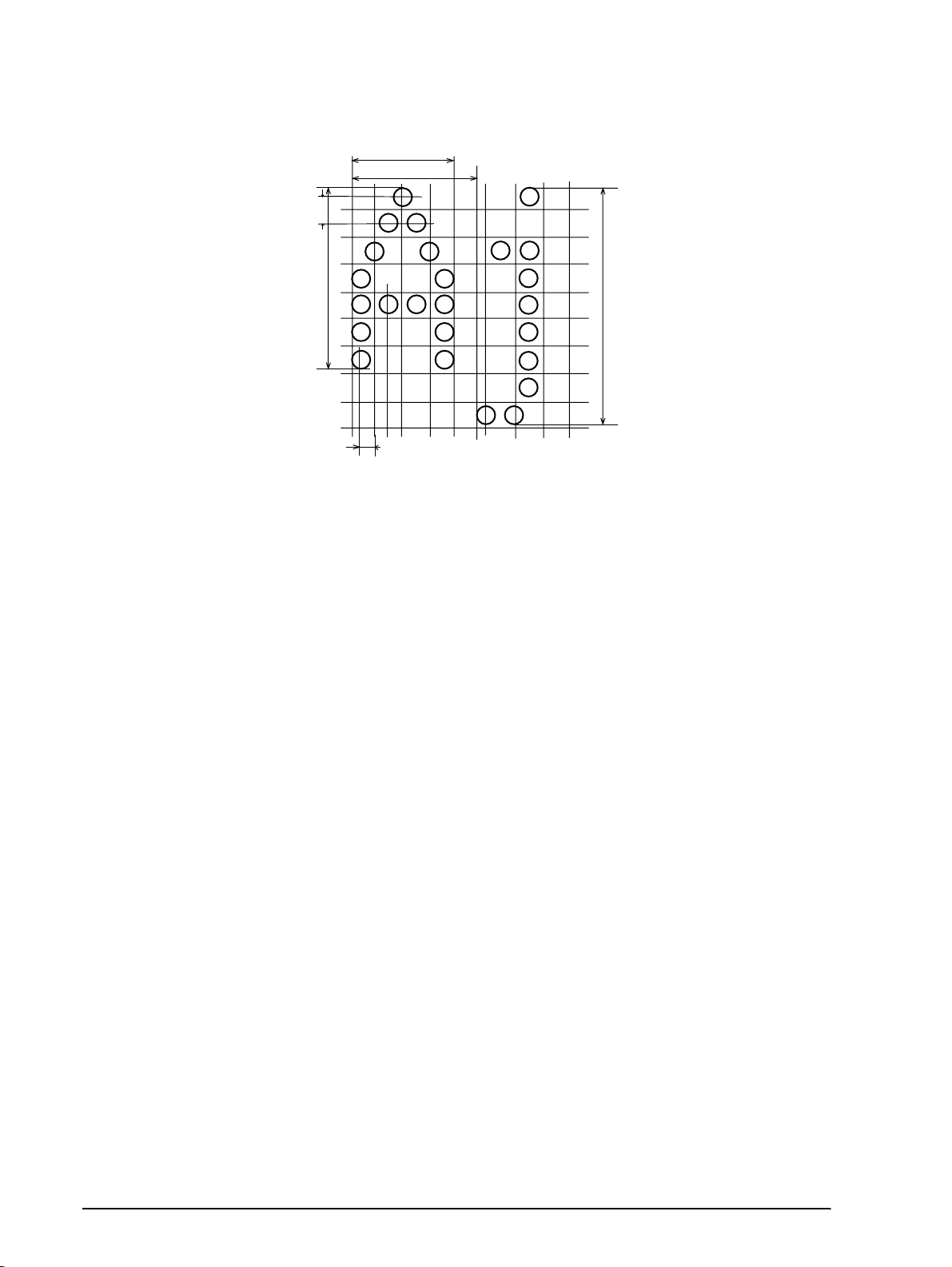
0.353 mm
(0.014")
2.4 mm
(0.094")
1.24 mm (0.049")
1.59 mm (0.063")
3.1 mm
(0.122")
Figure 1-3 Character size (7 x 9 font example)
1-4 Features and General Specifications Rev.B
Page 16

CONFIDENTIAL
Paper
Paper types: Paper roll: Plain paper
Paper roll width: 76 ± 0.5 mm (2.99 ± .020")
TM-U200D/U200PD Technical Manual
Pressure-sensitive paper
Paper roll maximum
83 mm (3.27")
diameter:
Paper roll core: Unless there is an optional near-end detector, you cannot use a
paper roll where the core and the paper are glued together.
Normal paper: Thickness: 1 sheet: 0.06 to 0.085 mm (.0024 to .0034")
Weight: 52.3 to 64 g/m
2
(13.9 to 17 lbs) (45 to 55 kg/
1000sheets/1091 x 788)
Pressure-sensitive paper Original 1 sheet + up to two copy sheets
Thickness: 1 sheet: 0.05 to 0.08 mm (.0020 to .0031")
Total thickness: 0.2 mm (.0079") or less
Recommended paper: Mitsubishi - Carbonless paper (blue)
Top and middle sheets: N40Hi (paper thickness: 0.06 mm [.0024"],
weight: 47.2 g/m
2
[12.6 lbs])
Bottom sheet: N60 (paper thickness: 0.08 mm [.0031"],
2
[18.1 lbs])
Copy capability and
ambient temperature for
weight: 68.0 g/m
Copying capability is influenced by the ambient temperature.
Printing must be performed under these conditions:
printing:
Original + 1 copy: 5° to 50° C (50° to 104° F)
Original + 2 copies: 10° to 40° C (41° to 122° F)
Rev. B Features and General Specifications 1-5
Page 17
CONFIDENTIAL
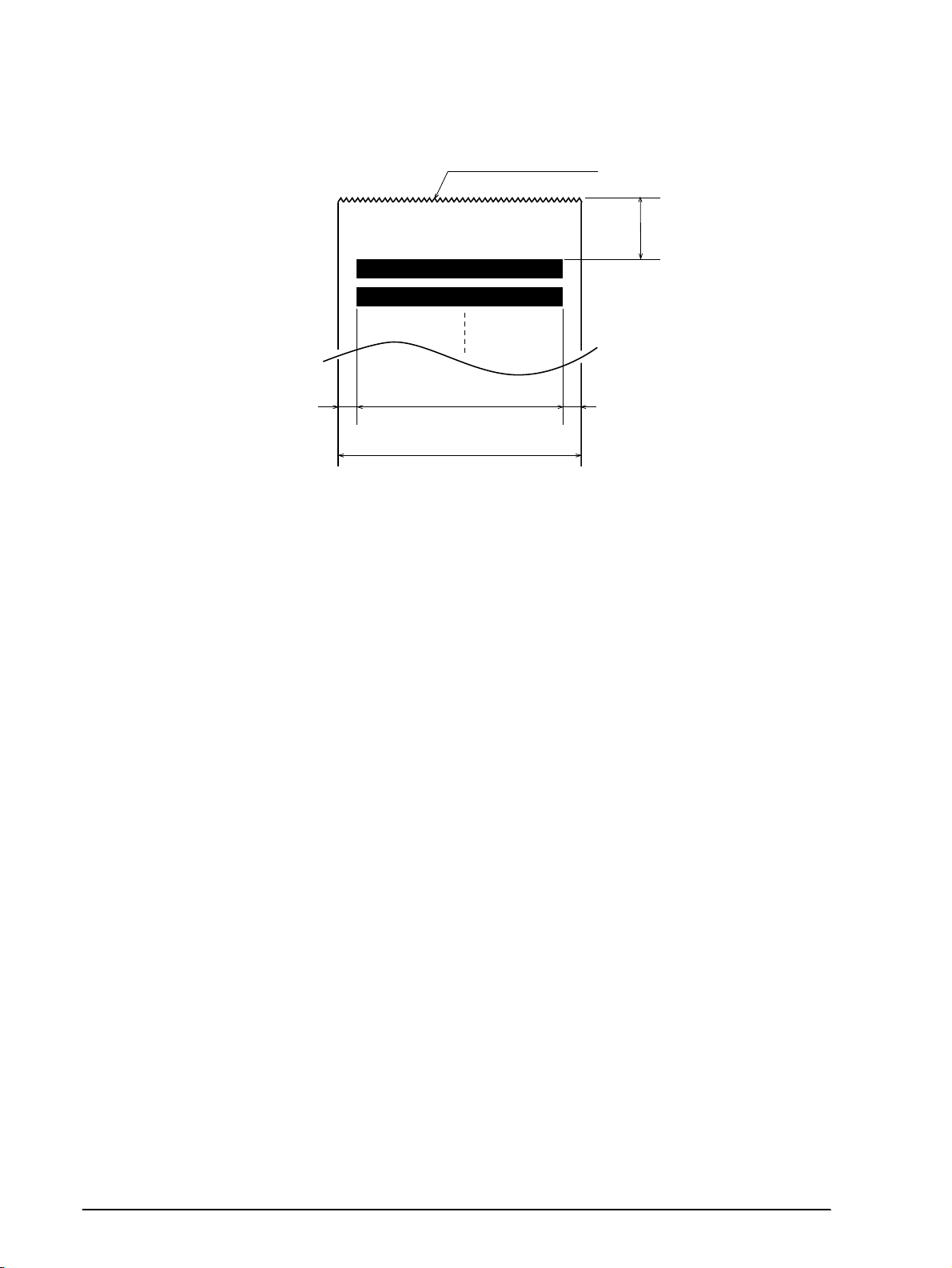
5.9 mm (0.23")
Cutting position (manual cutter)
20.2 mm (0.79") (*1)
(*2)
63.34 mm (2.49")
6.76 mm (0.27")
Maximum of 200 dots, 400 positions
76 mm (2.99")
Figure 1-4 Printing area
(*1) This dimension shows the distance from the manual cutter to the printing position.
(*2) The values shown for the printing area are the values calculated (between dot centers) according to the wire
diameter (0.29 mm [.011
]).
"
Paper Roll Supply Device
Supply device:
Drop-in loading
Receive Buffer
Either 1 KB or 40 bytes selectable by DIP switches.
1-6 Features and General Specifications Rev.B
Page 18
CONFIDENTIAL
Electrical Specifications
Power supply: One of the following five AC adapters is included, depending on
the specifications:
AC adapter specifications
Settings and
shipment
Japan 100V ± 10% 50/60 Hz PA-6508
North America 120V ± 10% 60 Hz PB-6509
Europe (Germany) 230V ± 10% 50 Hz PB-6510
Europe (U.K) 230V ± 10% 50 Hz PA-6511
Australia 140V ± 10% 50 Hz PA-6513
TM-U200D/U200PD Technical Manual
Input voltage range
Model
name
Power consumption
(except when driving
Mean: Average 43 W
Stand-by: Average 6 W
drawer kick-out):
Ribbon Cassette
Ribbon cassette specifications
Model number Color Ribbon life (*1)
ERC-38 (P) Purple 4 million chara c ters (under contin u ous printing at 25° C [7 7 ° F] )
ERC-38 (B) Black 3 million characters (under contin u ous printing at 25° C [7 7 ° F] )
ERC-38 (B/R)
(*1) The ribbon life is based on the following conditions:
Character font: 7 x 9 font (with descenders)
Printing pattern: ASCII 96-character rolling pattern. Refer to the specification published by EPSON for the
NOTE: Malfun ctions and other problems may occur if other than the sp ecified ribbo n ca ssette is used.
Black and
Red
printing pattern example.
Black: 1.5 million characters (under conti nuo us p rinting at 25° C [77° F])
Red : 750,000 characters (under continuous printing at 25° C [77° F])
Rev. B Features and General Specifications 1-7
Page 19
CONFIDENTIAL
External Dimensions and Weight
Height: 133 mm (5.19")
Width: 160 mm (6.25")
Depth: 248 mm (5.04")
Weight: Approximately 2.2 kg (4.85 lbs)
Color: EPSON standard gray.
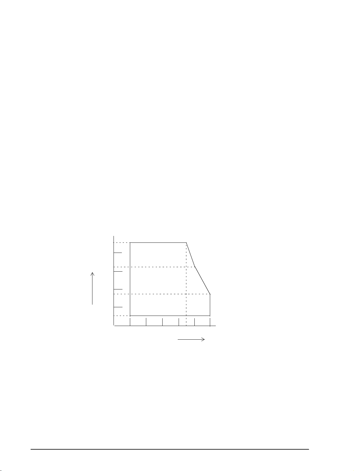
Environmental Specifications
Temperature: Operating: 0° to 50° C (32° to 122° F)
At 34° C (93° F) or higher, there are humidity restrictions;
please see the figure below.
Storage: -10° to 50° C (14° to 122° F) (except paper and ribbon)
Humidity: Operating: 10% to 90% RH (non-condensing)
Storage: 10% to 90% RH (non-condensing, except paper and ribbon)
90
80
60
40
20
Relative Humidity [%RH]
10
0
Operating Temperature Range
10 20 30
0
34 C, 90%
40 C, 65%
40
50 C, 35%
50
Environment Temperature [C]
Figure 1-5 Operating temperature and humidity range
Vibration resistance: When packed:
Frequency: 5 to 55 Hz
Acceleration: 2 G
Sweep: 10 minutes (half cycle)
Duration: 1 hour
Directions: x, y, and z
1-8 Features and General Specifications Rev.B
Page 20

CONFIDENTIAL
Impact resistance: When packed:
Reliability
Printer mechanism:
MCBF: 5,000,000 lines (excluding the print head)
Life: Approximately 7,500,000 lines (The printer is defined to have
TM-U200D/U200PD Technical Manual
Package: EPSON standard package
Height: 60 cm (23.62")
Directions: 1 corner, 3 edges, and 6 surfaces
When unpacked:
Height: 5 cm (1.97")
Directions: Lift one edge and release it (for all 4 edges).
reached the end of its life when it cannot function property
because of the main parts [motors, solenoids, frames, shafts, etc.]
wearing out.)
Print head life: 100,000,000 characters (when printing an average of two dots/
wire/character)
Safety and EMI Standards Applied
(EMC is measured with the packaged AC adapter)
For Europe: CE Marking: EN55022, EN50082-1, EN45501
Safety standards: TÜV
For USA: EMI: FCC class A
Safety standards: UL1950-2TH-D3
C-UL
For Japan: EMI: VCCI Class 1
Printer Installation Stance
Install the printer horizontally.
The printer must also be installed so that it d oes not move or vibr ate duri ng paper cutting or the
drawer kick-out operation.
Fastening tape is available as an option.
Rev. B Features and General Specifications 1-9
Page 21
CONFIDENTIAL
Hardware Configuration
Paper detector
switch sub-ass’y
Print head unit
Detector sub-ass’y
Motor, paper feed
Motor, carriage
Paper roll near-end detector(N.E-U200); (optional)
Interface circuit board
Main circuit board
Figure 1-6 TM-U200D/U200PD main unit configuration
1-10 Features and General Specifications Rev.B
Page 22

CONFIDENTIAL
Main Unit Specifications
Motor, Paper Feed
Type: 4-phase, PM type stepping motor
Drive voltage: 24V DC ± 10%
Winding resistance: 58 Ω ± 2.9 Ω at 25° C (77° F), per phase
Current consumption: Peak: 1.1 A in worst case
Motor, Carriage
Type: 4-phase, PM type stepping motor
TM-U200D/U200PD Technical Manual
Average: 200 mA at 24V DC, 25° C (77° F), 600 pps
350 mA maximum
Drive voltage: 24V DC ± 10%
Winding resistance: 39.5 Ω ± 1.9 Ω at 25° C (77° F), per phase
Current consumption: Peak: 1.5 A maximum
Average: 400 mA at 24V DC, 25° C (77° F), 952 pps
600 mA maximum
Print Head Unit
Solenoid number: 9
Winding resistance 15.6 Ω ± 5 % at 25° C (77° F), per phase
Drive voltage: 24V DC ± 10%
Detector Sub-ass’y
Type: Photo sensor
Voltage: 5V DC ± 5%
Output level: Low when the carriage home position is detected
Rev. B Features and General Specifications 1-11
Page 23
screw
CONFIDENTIAL
Paper Detector Switch Sub-ass’y
Type: Microswitch
Voltage: 5V DC ± 5%
Output level: High when paper end is detected
Near-end Detector (N.E.-U200); (Optional)
Type: Microswitch
Voltage: 5V DC ± 5%
Output level: Low when a paper near-end is detected
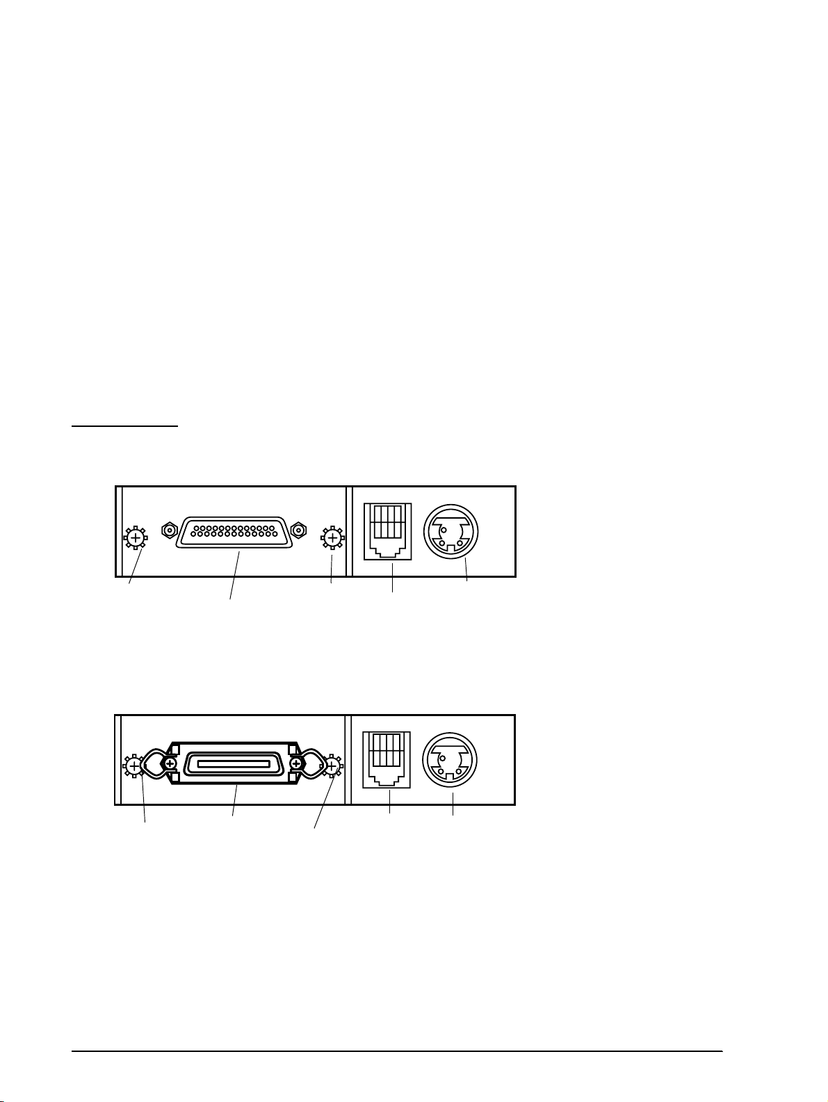
Connectors
Frame ground screw
Interface connector
Frame ground
screw
Interface connector
Interface Connector
See the interface section.
Frame ground screw
Drawer kick-out
connector
Power supply
connector
Figure 1-7 Connector panel (serial interface)
Frame ground
Drawer kick-out
connector
Power suppl
connector
Figure 1-8 Connector panel (parallel interface)
1-12 Features and General Specifications Rev.B
Page 24
CONFIDENTIAL
Power Supply Connector
This connector is used to connect the printer to an external power source.
Pin assignments: See the table below.
Model (printer side): Hosiden TCS7960-532010 (or equivalent)
Power supply connector pin assignments
Pin Number Signal Name
1 +30V DC unregulated
2GND
3NC
Shell Frame GND
NOTE: Be sure to ground the frame ground (FG) screw on the board at the bottom of the unit. Ground wire terminal
hole diameter: 3.2mm (.13"). Ground wire thickness: AWG 18 or equivalent.
TM-U200D/U200PD Technical Manual
Drawer Kick-Out Connector
A pulse specified by the ESC p command is output to the drawer kick-out connector. The host
can confirm the status of the input signal by using the GS a, GS r, or DLE EOT commands.
Drawer kick-out connector pin assignments
Pin Number Signal name Direction
1Frame GND 2 Drawer kick-out drive signal 1(*2) Output
3 Drawer open/close signal (*1) Input
4 +24V DC 5 Drawer kick-out drive signal 2 (*2) Output
6 Signal GND -
(*1) Drawer open/close signal
The host computer can check the drawer open/close status with the DLE EOT, GS a, and GS r
commands.
Input signal level: LOW = 0 V
HIGH = 2 to 5V (at connector pin 3)
Rev. B Features and General Specifications 1-13
Page 25
CONFIDENTIAL
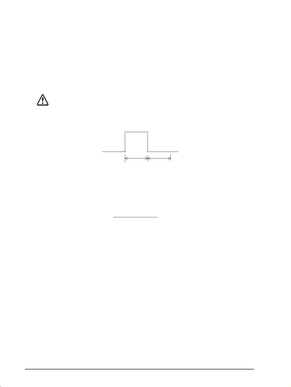
(*2) Drawer kick-out drive signal
Output signal: Voltage = Approximately 24V DC
Output waveform: Outputs the waveforms in Figure 1-8 to pins
CAUTION:
To avoid an overcurrent, the resistance of the drawer kick-out solenoid must be 24 Ω or
more.
Current = 1 A or less
2 and 5 of the connector. t1 (ON time) and t2
(OFF time) are specified by
ESC p
.
t1 x 2 ms
Figure 1-9 Drawer kick-out drive signal output waveform
NOTES:
❏ Two driver transistors cannot be energized simultaneously .
❏ The drawer drive duty must be as shown below:
ON time
(ON time + OFF time)
❏ Be sure to use the printer power supply (connector pin 4) for the drawer power source.
t2 x 2 ms
≤
0.2
1-14 Features and General Specifications Rev.B
Page 26

CONFIDENTIAL
Interface
RS-232 Serial Interface
Data transmission: Serial (compatible with RS-23 2)
Synchronization: Asynchronous
Handshaking: DTR/DSR or XON/XOFF control
Signal levels: MARK = -3 to -15 V: Logic 1/OFF
Baud rates: 4800, 9600 bps
Data word le ngths: 7 or 8 bits
Parity settings: None, even, odd
TM-U200D/U200PD Technical Manual
SPACE = +3 to +15 V: Logic 0/ON
Stop bits: 1 or more
Connector: Female D-SUB 25-pin connector
NOTES:
❏ Handshaking, data word length, baud rate, and parity depend on DIP switch settings.
❏ Data transmitted from the printe r has 1 stop bit (fixed).
Rev. B Features and General Specifications 1-15
Page 27
CONFIDENTIAL
Interface Connector Pin Assignments
TM-U200D printer status and signals
Pin number Signal name I/O Function
1FG-Frame ground
2 TXD O Transmit data
3 RXD I Receive data
4 RTS O Same as the DTR signal
6 DSR I This signal indicates whether the host compu ter can rec eive dat a.
7 SG - Signal ground
20 DTR O 1) When DTR/DSR control is selected, this signal indicates whether the printer is
SPACE indicates that the host computer can receive data, and MARK indicates
that the host computer cannot receive data.
When DTR/DSR control is selected, the printer transmits data after confirming this
signal (except when transmitting data by DLE EOT and GS a).
When XON/XOFF control is selected , the pri nt er do es not check t hi s signal.
Changing the DIP switch setting enables this signal to be used as a reset signal
for the printer.
The printer is reset when the signal remains MARK for 1 ms or more.
busy. SPACE indicates that the printer is ready to receive data, and MARK
indicates that the printer is busy. The busy condition can be changed by using
DIP SW 1-8 as follows:
DIP SW 1-8 status
Printer
1. During the period from when the power is turned on
(including resetting using the interface) to when the
printer is ready to receive data.
2. During the self-test BUSY BUSY
3. During paper feeding using the paper feed button. - BUSY
Off-line
4. When the printer stops printing due to a paper-end. - BUSY
5. When an error has occurred. - BUSY
6. When a temporary abnormality occurs in the
power supply voltage
7. When the receive buffer becomes full. (*1) BUSY BUSY
20 DTR O 2) When XON/XOFF co n tro l is sel ec t ed :
25 INIT I Changing the DIP switch setting enables this signal to be used as a reset signal
This signal indicates whether the printer is correctly connected and is ready to
receive data. SPACE indicates that the printer is ready to receive data. The
signal is always SPACE except in the following cases:
❏ During the period after the power is turned on until the printer is ready to
receive data.
❏ During the self test.
for the printer (see the DIP switch settings in the “Buttons and Switches” section
of this chapter). The printer is reset when the signal remains SPACE for 1 ms or
more.
ON OFF
BUSY BUSY
-BUSY
1-16 Features and General Specifications Rev.B
Page 28

CONFIDENTIAL
NOTES:
❏ When the remaining space in the receive buffer is 16 bytes, the printer becomes buffer-full. This status continues
until the space in the receive buffer increases to 32 bytes.
❏ The printer ignores the data received when the rem ain in g space in the recei ve buffer is 0 bytes.
On-line/Off-line switching
The printer does not have an on-line/off-line button. The printer goes off-line under the
following conditions:
Between the time when the power is turned on (including reset using the interface) and
❏
when the printer is ready to receive data.
During the self-test.
❏
During pa per feeding using the PAPER FEED button.
❏
Between the time when the printer stops printing due to a paper-end and when the on-line
❏
recovery wait time finishes after loading paper (in cases when empty paper supply is
detected by either the paper roll end detector or the paper roll near-end detector with a
printing halt feature set enabled due to paper shortage by ESC c 4).
TM-U200D/U200PD Technical Manual
When an error has occurred.
❏
XON/XOFF transmit timing
When XON/XOFF control is selected, the printer transmits XON or XOFF signals as follows.
Printer status
• When the printer goes on line after turning on th e pow er or
XON
transmission
XOFF
transmission
(*1) XON is not transmitted when the receive buffer is full.
(*2) XOFF is not transmitted when the receive buffer is full.
NOTE: The XON code is <11>H and th e XOFF code is <13>H.
reset using interface.
• When the receive buffer is released from the buffer full state.
• When the printer switches from off line to on line (*1).
• When the printer recovers from an error through a command.
• During an error condition
• When the receive buffer becomes full (*2).
DIP SW 1-8 stat us
ON OFF
Transmission
Transmission
----
----
Transmission
Transmission
----
Transmission
Transmission
Transmission
Transmission
Transmission
Transmission
Transmission
Rev. B Features and General Specifications 1-17
Page 29

CONFIDENTIAL
Serial interface connection example
Host
TXD
DSR
CTS
RXD
DTR
FG
SG
NOTES:
❏ Set the handshaking so that the transmit data can be received.
❏ Transmit data to the printer after turning on the power and initializing the printer.
RS-485 Serial Interface (option)
Refer to the Appendix for details.
IEEE 1284 Parallel Interface
Printer
RXD
DTR
RTS
TXD
DSR
FG
SG
Copyright (C) 1994 by the Institute of electrical and Electronic Engineers, Inc.
Specification
Data transmission: 8-bit parallel
Synchronization: Externally supplied nStrobe signals
Handshaking: nAck and Busy signals
Signal levels: TTL compatible
Connector: 57RE-40360-830B (DDK) or equivalent (IEEE 1284 Type B)
Reverse communication (Printer Host): Nibble or Byte Mode
Reverse Mode (Data Transmission from Printer to Host)
The STATUS data transmission from the printer to the host is proceeded in the Nibble or Byte
mode.
This mode allows data transmission from the asynchronous printer under the control of the
host.
Data transmissions in the Nibble Mode are made via the existing control lines in unists of four
bits (Nibble). In the Byte Mod e, data transmissions are proceeded by making the eight-bit data
lines bidirectional.
1-18 Features and General Specifications Rev.B
Page 30

CONFIDENTIAL
The both modes fail to be proceeded concurrently with the Compa tibility Mode, ther eby causing
half duplex transmission.
The IEEE 1284 Nibble/Byte Modes are under development in the form of draft and may be
subject to change.
TM-U200D/U200PD Technical Manual
Rev. B Features and General Specifications 1-19
Page 31

CONFIDENTIAL
Interface Connector Pin Assignments
TM-U200PD printer status and signals
Pin number Source Compatibility Mode Nibble Mode Byte Mode
1 Host nStrobe HostClk HostClk
2 Host/Ptr Data0(LSB) Data0(LSB) Data0(LSB)
3 Host/Ptr Data1 Data1 Data1
4 Host/Ptr Data2 Data2 Data2
5 Host/Ptr Data3 Data3 Data3
6 Host/Ptr Data4 Data4 Data4
7 Host/Ptr Data5 Data5 Data5
8 Host/Ptr Data6 Data6 Data6
9 Host/Ptr Data7(MSB) Data7(MSB) Data7(MSB)
10 Printer nAck PtrClk PtrClk
11 Printer Busy PtrBusy/Data3,7 PtrBusy
12 printer PError
13 Printer Select Xflag/Dat a1,5 Xflag
14 Hostr nAutoFd HostBusy HostBusy
15 NC ND ND
16 GND GND GND
17 FG FG FG
18 Printer Logic-H Logic-H Logic-H
19-30 GND GND GND
31 Host nInit nInit nInit
32 Printer nFault nDataAvail/Data0,4 nDataAvail
33 GND ND ND
34 Printer DK_STATUS ND ND
35 Printer +5V ND ND
36 Host nSelectIn 1284-Active 1284-Active
AckDataReq/
Data2,6
AckDataReq
NOTES:
❏ A prefix "n" to signal names refers to "L" active signals. To the host provided with none of the sig nal lin es listed
above, both-w ay communication fails .
❏ For interfacing, signal l ines shall use twisted pair cables with the return side s conne cted to signal ground level.
❏ Interfacing conditions shall be all based on the TTL level to meet the characteristics described below. In addition,
both rise time and fall time of each signal shall be 0.5Js or less.
❏ Data transmission shall not ignore the signal nAck or Busy. An attempt to transmit data with either signal, nAck or
Busy, ignored can cause lost data. (Data transmissions to the printer shall be made after verifying the nAck signal
or while the Busy signal is at the "L" level.)
❏ Interface cables shall be as minimum requ ired sho rt in leng th as po ssibl e.
NC: No Connect
ND: No Defined
1-20 Features and General Specifications Rev.B
Page 32

CONFIDENTIAL
Switching between on-line and off-line
The printer is not equipped with any on-line/off-line switch. The printer is placed into off-line
status in either of the followings:
❏ When the power is turned on or until the printer becomes ready for data transmission after it
is initialized by the reset sign al (nInit) from the interface.
❏ In the process of self-test.
❏ In the process of paper feeding using the paper feed switch.
❏ Between the time when the printer stops printing due to a paper-end and when the on-line
recovery wait time finishes after loading paper. (in cases when empty paper supply is
detected by either the paper roll end detector or the paper roll near-end detector with a
printing halt feature set enabled due to paper shortage by ESC c 4).
❏ When an error has occurred.
Reception of status from the printer through the bid ire ctional parallel interface
In the bidirectional parallel interface specifications, the printer status transmission is available
by using the both-way communicati on facility in the Ni bble/By te Modes in acco rdance wi th the
IEEE 1284.
In this case, different from in the RS-232 serial interface specifications, the real-time
interruptions from the printe r to the host are disabled and thus precau tions must be tak en to the
followings.
TM-U200D/U200PD Technical Manual
❏ Allowable capacity of the printer internal buffer is 100 bytes (except ASB status). The status
signals exceeding this capacity will be discarded. To prevent possible loss of status, the host
shall be ready for data acception (Reverse Mode).
❏ When ASB is used, the host is preferably in the wait state for data acception (Reverse Idle
Mode). When this state is not available, the host shall enter the Reverse Mode to always
monitor the presence of data.
❏ When ASB is used, preference shall be given to the ASB status for transmission over the
other status signals. Any accumulated ASB status signals left for transmission from the last
to the newest ASB status transmission shall be transmitted together at a time as one ASB
status showing the presence of change, followed by the lastest ASB status.
Example: In the normal (wait) state, the ASB status is configured as follows:
First Status Second Status Third Status Fourth Status
0001 0000 0000 0000 0000 0000 0000 0000
When a sequence of operations are proceeded, the PAPER FEED button is pressed and released,
the following pieces of data are accumulated.
Rev. B Features and General Specifications 1-21
Page 33

CONFIDENTIAL
First Stat us Second Status Third Status Fourth Status
➀ 0001 0000 0000 0000 0000 0000 0000 0000
➁ 0101 1000 0000 0000 0000 0011 0000 0000
➂ 0001 0000 0000 0000 0000 0011 0000 0000
When the ASB status is received following this, a total of eight (8) bytes of ASB will be
transmitted as follows:
Accumulated ASB (
Accumulated ASB (➀
+ First Status Second Status Third Status Fourth Status
The latest ASB (➂)
Fourth Status
➀+➁+➂)
Near end
detection
FEED button is
pressed
FEED button is
released
First Status Second Status Third Status Fourth Status
+➁+➂) 0101 0000 0000 0000 0000 0000 0000 0000
0001 0000 0000 0000 0000 0000 0000 0000
Notes on setting DIP switc h 1-8 to ON
The printer mechanism stops but does not become busy when an error has occurred, printing
stops due to a paper end, or paper is fed using the FEED button.
When setting DIP switch 1-8 to ON to enable handshaking with the print e r, be sure to chec k the
printer status with GS a and ASB function. In this setting, the default value of n for GS a is 2.
The printer automatically transmits the printer status, depending on on-line/off-line changes.
When using DLE EOT and DLE ENQ, be sure that the receive buffer does not become full.
When using a host that cannot transmit d ata when the p ri nter is busy and if an er ror occu rs,
❏
DLE EOT and DLE ENQ cannot be used when printer is busy due to receive buffer-full
state.
If the host can transmit data when the printer is busy and, the receive buffer becomes full
❏
while the host is sending bit-image data, a DLE EOT or DLE ENQ command used while
sending bit-image data is processed as bit-image data, not as a command. Secondly, any
data transmitted when the receive buffer is full may be lost.
Example: Check the printer status using GS r after tr ansmit ti ng each line of data and use the 1K
byte receive buffer. Transmit one line of data so that the receive buffer does not become full.
1-22 Features and General Specifications Rev.B
Page 34

CONFIDENTIAL
Buttons and Switches
Power Switch
Type: See-saw type
Function: The power switch turns the power on or off.
Note:
Turn on the power only after connecting the power supply.
RAM is completely initialized when the printer is turned off using the power switch.
Panel Button
The panel button is enabled or disabled by the ESC c 5 command. This button is inactive if it is
disabled.
Feed (FEED) button: Type: Non-locking push button
TM-U200D/U200PD Technical Manual
Function: Feeds paper based on the line feed amount set by ESC 2
and ESC 3.
Note:
The ESC c 5 command enables or disables the panel button. When disabled, the button will not
function. However, when loading a paper roll, you can feed paper with the FEED button during the
paper loading waiting time if the paper loading waiting time is set by GS z 0. Press the FEED
button again after the PAPER OUT LED starts blinking to return the printer to the on-line state.
Rev. B Features and General Specifications 1-23
Page 35

CONFIDENTIAL
DIP Switches
Serial interface (RS-232 an d RS -485 (option))
The DIP switches of are located at the bottom of the case.
DIP switch 1
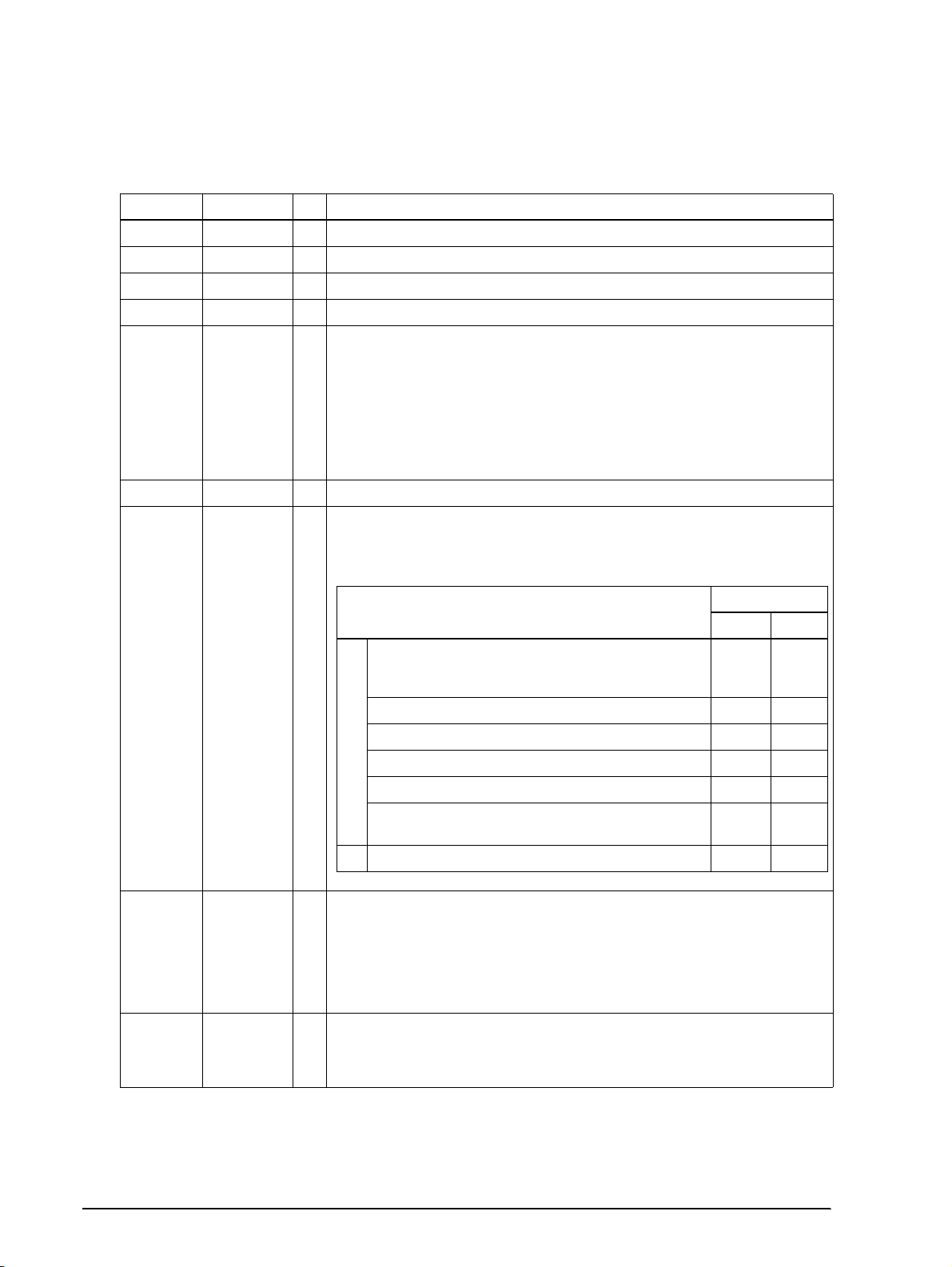
DIP Switch Function ON OFF
1 Data receive error Ignored Prints “?”
2 Receive buffer capacity Data buffer 40 bytes Data buffer 1 KB
3 Handshaking XON/XOFF DTR/DSR
4 Data word length 7 bits 8 bits
5 Parity check Yes No
6 Parity selection Even Odd
7 Baud rate selection 4800 bps 9600 bps
8 Busy condition When the receive buffer is full
When the receive buffer is full
at an off-line status
DIP switch 2
DIP Switch Function ON OFF
Selects spacing between characters. See
1
2
3 I/F pin 6 reset signal Enabled Disabled
4 I/F pin 25 reset signal Enabled Disabled
NOTES:
❏ Changes in DIP switc h setti ng s (ex cluding switche s 2-3 and 2-4, whi c h ar e I/F reset sign als) are recognized only
when the printer power is turned on or reset usin g the in t erface . If the DIP swit ch setting is cha nged afte r the
printer power is turned on, the change does not take effect until the printer is turned on again or reset.
❏ Do not change the settings of DIP switches 2-3 and 2-4 when the printer power is on.
the table on page 1-3 for the number of
characters per line for each setting.
For internal use only
Setting must not be changed. (Fixed to OFF.)
2 half dots 3 half dots
Parallel interface (IEEE 1284)
The DIP switches of are located at the bottom of the case.
DIP switch 1
DIP Switch Function ON OFF
1 Auto line feed Enabled D isabled
2 Receive buffer 40 bytes Approximately 1K byte
3-7 Undefined
8 Busy condition
Receive buffer-full
Scanning data
Off-line
Receive buffer-full
Scanning da ta
1-24 Features and General Specifications Rev.B
Page 36

CONFIDENTIAL
.
DIP switch 2
DIP Switch Function ON OFF
1
2 Internal use (*1)
3Undefined
4 I/FnInit reset signall Enabled Disabled
NOTES:
❏ Do not change the setting of DIP switch 2-2 (fixed to OFF).
❏ Changes in DIP swit ch settings (excludin g sw itc h 2 -4 , wh ich is I/F reset sign al ) are recognized only wh en the
printer power is turned on or reset using the interface. If the DIP switch settings are changed after the printer
power is turned on, the change does not take effect until the printer is turned on again or reset (excluding switch
2-4).
Print colum n selection
7 ✕ 9 font/9 ✕ 9 font
TM-U200D/U200PD Technical Manual
42CPL/35CPL 40CPL/33CPL
Rev. B Features and General Specifications 1-25
Page 37

CONFIDENTIAL
Panel LEDs
Power (POWER) LED: Green
Off: Power supply of +24V is not sta ble.
On: Power supply of +24V is stable.
Paper roll near -end
(PAPER OUT) LED:
(*1) Near-end detector is an option.
Error (ERROR) LED: Red
Red
On: Paper roll near-end is detected. (*1)
Off: Adequate paper remains on the paper roll (normal
Blinking: Waitin g for restarting test printing on paper roll or
On: Off-line (except during paper feeding using the
Off: Normal operation.
Blinking Error state. (Refer to the Error types and
condition).
for return to on-line status after automatic paper
feeding.
FEED button and during the self-test).
countermeasures in Chapter 4.)
Self-test
Performing the Self Test
The printer has a self-test function that checks the following:
❏ Control circuit functions
❏ Printer mechanisms
❏ Print quality
❏ Control ROM version
❏ DIP switch settings.
See Chapter 4 for instructions on running a self-test.
1-26 Features and General Specifications Rev.B
Page 38

CONFIDENTIAL
Error Processing
Printer Operation When an Error Occurs
The printer executes the following operations upon detecting an error:
❏ All mechanical operations stop
❏ Goes off-line (if DIP switch 1-8 is set to OFF)
❏ The ERROR LED blinks.
Error recovery
The TM-U200D recovers from an error state when you turn off the power, correct the error, and
then turn the power back on.
Data Receive Error
If one of the following er ro rs o ccur s, the pr int er prints “?” or ignores t he d ata , d epend ing on the
setting of DIP switch 1-1:
TM-U200D/U200PD Technical Manual
❏ Parity erro r
❏ Framing error
❏ Overrun error.
Buffer Full Printing
When subsequent data is received after the printer processes one line of data in the print buffer,
the printer automatically prints the processed data and feeds the paper one line. When the
printer detects no paper, it does not print until new roll paper is loaded.
Detectors and Printing
When the printer detects a paper nea r-end, it stops or c ontinues pri nting, d ependin g on the ES C
c 4 command setting. The roll paper detector always halts printing when there is no paper.
Rev. B Features and General Specifications 1-27
Page 39

CONFIDENTIAL
Hexadecimal Dump
Hexadecimal Dump Function
This function prints the data transmitted from the host computer in hexadecimal numbers and
in their corresponding characters.
Performing a Hexadecimal Dump
1. Turn the printer power off.
2. Set DIP switch 1-2 to on to select 40 bytes for the receive buffer capacity.
3. Turn the power on while pressing the FEED button.
4. Before finishing the initializat ion of the p rinter , release t he FEED button, t hen press the FEED
button again. The printer first prints "Hexadecim al Dump" on the paper roll, and prints the
data received thereafter in hexadecimal numbers and their corresponding characters until
the printer is turned off.
NOTES:
❏ "." is printed if no printable ASCII character corre s ponds to the data received.
❏ During the hexadecimal dump, all commands except DLE EOT and DLE E N Q are disabled.
❏ Insufficient print data to fill the last line can be printed by setting the printer off line. (See to On-line/off-line
switching.)
Sample hexadecimal dump
Hexadecimal Dump
1B 21 00 1B 26 02 40 40 1B 69 : . ! . . & . @ @.i
1B 25 01 1B 63 34 00 1B 30 31 : . % . c4 . .. 01
41 42 43 44 45 46 47 48 49 4A : ABCDEFGHIJ
Options
Paper roll near end detector
❏
External power supply PS-170
❏
Printer fastening tape (DF-10)
❏
RS-485 serial interface
❏
1-28 Features and General Specifications Rev.B
Page 40

CONFIDENTIAL
External Power Supply PS-170
Specifications
100V, 120V, or 230V (specified at time of purchase)
Input Conditions
Input voltage (rating) 90 to 264 V
Frequency (rating) 50 to 60 Hz +/-3Hz
Input current (rating) less than 100 VA
AC switch None
TM-U200D/U200PD Technical Manual
(100VAC - 10% to 230VAC + 15%)
108 V AC to 132 V (120V type)
Energizing LED None
Output specifications
Output voltage (rating) 24 VDC ±5%
Output voltage (rating ) 2.0 A
Output electric power
(rating)
Output peak current 4.5 A (within 300 msec)
Compliance to safety regulation
The following standards is applied only to the equipments with marks and statements
UL/C-UL/TÜV
NOTE: Use only the EPSON PS-170 power supply to avoid damage to the printer and the power supply.
48 W
Rev. B Features and General Specifications 1-29
Page 41

CONFIDENTIAL
Chapter 2
Mechanism Configuration and Operating Principles
Printer Mechanism Operating Principles
The printer mechanism M-U200 mounted in the TM-U200D/U200PD is composed of four
mechanisms: print, paper feed, ribbon feed, and detector. In addition to the above four
mechanism, the 2-color Print Version has a ribbon switch mechanism.
TM-U200D/U200PD Technical Manual
(Single-color Print Version)
(2-color Print Version )
Figure 2-1 M-U200D
Rev. B Mechanism Configuration and Operating Principles
Page 42

d
CONFIDENTIAL
Print mechanism unit
The print mechanism unit consists of the parts shown in the figure below.
Pulley, belt
tension
Shaft, carriage
guide
Carriage subass’y
Shaft, carriage
Earth plate,
print head ass’y
Print head unit
Figure 2-2 Print mechanism unit
Belt
Frame, paper fee
ass’y
Motor, carriage
ass’y
FFC, print head
2-2 Mechanism Configuration and Operating Principles Rev.B
Page 43

Paper roll
CONFIDENTIAL
Print head unit movement
When the Motor, carriage is driven and the Gear, carriage motor is moved in the direction of
arrow B (forward rotation), the rotational power is conveyed to the Pulley, belt drive, then
the belt. Next the Carriage sub-ass’y, which is fixed to the belt, is moved in the direction of
arrow B.
When the Gear, carriage motor is rotated in the direction of arrow A (reverse rotation), the
Carriage sub-ass’y is moved in the direction of arrow A.
TM-U200D/U200PD Technical Manual
Belt
B
Carriage sub-ass’y
Gear, carriage motor
A
A
Pulley, belt drive
B
B
A
A
B
Figure 2-3 Print head unit movement
Wire movement when a single dot is printed
When the specified print head drive pulse is input to the drive coil, the iron core is magnetized,
and the actuating plate is pul led i n the d i rect ion of arr ow A. T his action pushes the wire toward
the platen. When the wire strikes the ink ribbon and paper against the platen(*), a single dot is
printed.
When the energizing of the drive coil is completed, the wire and actuating plate are returned to
the standby position by the wire return spring and actuating plate spring.
(*) The “platen” is the portion of the Frame, paper feed being struck by the wires during
printing.
Actuating
plate
Wire return
spring
A
Ink ribbon
B
Wire
Drive coil
Wire guide
Iron core
Platen
Figure 2-4 Printing
Rev. B Mechanism Configuration and Operating Principles
Page 44

CONFIDENTIAL
Printing a character (9x9 font)
A character is printed by energizing the print solenoids with respect to the Carriage sub-ass’y
portion (the reference timing for the print solenoids is the Motor, carriage phase switching
signals). The print head unit is moved 0.317 mm (0.012”) (in approximately 1.05 ms) each time
the Motor, carriage is rotated one step (7.5°).
To print character “2,” print solenoids 2 and 9 are energized first at the same timing as the
Motor, carriage phase switching signal. Then, print solenoid 8 is energized at TnH (being
delayed a half dot). The remaining print solenoids are energized correspondingly, and the
character “2” is finally printed.
Motor, carriage phase
switch timing
Print solenoid
Figure 2-5 Print timing chart
Tn+2Tn+1 Tn+3
TnH(4)
Tn+5Tn+4
TnH
Tn
1
2
3
4
5
6
7
8
9
2-4 Mechanism Configuration and Operating Principles Rev.B
Page 45

CONFIDENTIAL
Paper Feed Mechanism Unit
The paper feed mechanism unit consists of the parts shown in the figure below.
Paper feeding is performed by driving the Motor, paper feed (stepping motor).
TM-U200D/U200PD Technical Manual
Roller, paper hold
Spring,
paper hold
Shaft, paper hold roller
Figure 2-6 Paper feed mechanism unit
Roller, paper
Gear, paper feed reduction
feed ass’y
Paper feed, upper
Frame, paper feed ass’y
Motor, paper feed
Rev. B Mechanism Configuration and Operating Principles
Page 46

CONFIDENTIAL
Paper loading (semi-automatic loading)
When the paper roll is manual ly inser te d in to the Roller , p aper feed , t he pa per det ecti on switc h
in the paper path detects the paper, and semi-automatic loading (*) is executed.
(*) Semi-automatic loading is the function that automatically feeds the paper to the top of the
Frame, paper feed assembly when the paper roll is inserted in the paper path when the main
cover is open and the detector detects no paper.
Paper feeding
Spring, paper
hold plate
Roller, paper hold
Paper
frame, paper feed
Paper guide, upper
Roller, guide
Case, upper
Roller, paper feed
Frame, base ass’y
Figure 2-7 Paper loading
Paper feeding is performed by conveying the rotational power of the Motor, paper feed to the
gear of the Motor, paper feed through the Gear, paper feed reduction, Gear, paper feed , and
Roller, pap er feed .
Since the Roller, paper feed and Roller, paper hold are pressed together, paper is advanced to
the top of the Frame, paper feed assembly by the fr iction between the rubber of the Rol ler, paper
feed and the Roller, paper hold .
2-6 Mechanism Configuration and Operating Principles Rev.B
Page 47

CONFIDENTIAL
During printing, the Motor, paper feed is driven after each line is printed, causing the paper to
be fed a specified amount. While the FEED button on the switch panel is pressed, the Motor,
paper feed is driven and the paper roll is fed.
TM-U200D/U200PD Technical Manual
Paper roll
Roller, paper hold
Roller, paper feed
Gear, paper feed
motor
Gear, paper feed
reduction
Gear, paper feed
Figure 2-8 Paper feeding
Ribbon Feed Mechanism Unit
The ribbon feed mechanism unit consists of the parts shown in the figure below. The printer
feeds the ribbon automatically as the Motor, carriage rotates .
Ribbon cassette
Gear, ribbon intermediate
Frame, ribbon
assembly
Plate, ribbo n drive
ass’y
Gear, ribbon transmission
Figure 2-9 Ribbon feed mechanism unit
Ribbon take-up
ass’y
Rev. B Mechanism Configuration and Operating Principles
Page 48

CONFIDENTIAL
Ribbon feeding
When the Motor, carriage rotates forward and the Gear, carriage motor rotates in the direction
of arrow A, the Gear, ribbon intermediate and Gear, ribbon drive rotate in the directions of
arrows B and C, respectively. This causes the Plate, ribbon drive to move in the direction of
arrow D, with the Gear, ribbon intermediate shaft in the center, until the Gear, ribbon drive
engages the Gear, ribbon transmission .
Since the Gear, ribbon transmis sion and the Gear, r ibbon take-up are always engaged , the Gear,
ribbon take-up rotates in the direction of arrow E.
When the Motor, carriag e rot ates in the r everse d irect ion and t he Gear, ca rriag e motor rota tes in
the direction of arrow F, t he Pl at e, ri bbon dr ive moves in the direction of arrow G, disengaging
the Gear, ribbon drive from the Gear, ribbon transmission .
Therefore, the Ribbon take-up ass’y rotates in the direction of arrow E only when the Motor,
carriage rotates forward. Then the ribbon feed and ribbon hold rollers in the Ribbon cassette ,
which are engaged with the Ribbon take-up ass’y , rotate and the ribbon is fed.
Gear, ribbon driv e
Gear, ribbon transmission
Gear, carriage motor
F
A
B
C
D
G
Figure 2-10 Ribbon feeding
Gear, ribbon intermediate
Ribbon take-up
ass’y
E
Gear, ribbon take-up
2-8 Mechanism Configuration and Operating Principles Rev.B
Page 49

CONFIDENTIAL
Detection Mechanism Unit
The detection mechanism unit consists of the home position detection, paper detection, and
near-end detection (optional) mechanisms.
TM-U200D/U200PD Technical Manual
Paper detector
Detector
Figure 2-11 Detection mechanism unit
Home position detection mechanism
The home position detection mechanism consists of the detection protrusion at the left side of
the Carriage sub-ass’y and the Detector sub assembly at the left side of the base frame. It
determines the home position, identifies the carriage position, and detects Carriage sub-ass’y
operation errors.
The Detector sub assembly consists of an LED and photo transistor. When the Carriage subass’y moves, the detection protrusion passes between the LED and photo transistor and blocks
the optical axis of the photo transistor, changing the output level of the photo transistor.
The change in the output level is used as a signal to detect the movement of the Carriage subass’y.
Printer side
The light is blocked
+5V
The light is
not blocked
High
A
Low
GND
Carriage sub-ass ’ y detection protru si on
Signal level at A
Figure 2-12 Home position detection diagram
Rev. B Mechanism Configuration and Operating Principles
Page 50

CONFIDENTIAL
Paper detection mechanism
The paper detection mechanism is located in the paper path. The mechanism provides end
detection of the paper roll and semi-automatic loading by detecting presence or absence of the
paper roll when it is inserted. Since the paper detector switch sub assembly is a micro switch, it
is always ON when the paper roll is loaded.
Near-end detection mechanism (optional)
The near-end detector ass’y consists of the Lever , N.E. detection and a microswitch detect or and
is located on the right side of the Case, lower. This detector detects the amount of paper left on
the paper roll.
The tip of the Lever, N.E. detection is always pressed against the edge of the paper roll by a
spring inside the microswitch. Therefore, when there is a large amount of paper remaining on
the roll, the Lever, N.E. detection is pressed against the side of the paper roll as depicted by the
solid lines in the figure below. This keep s the microswitch tur ned on. When the amount of pape r
left on the roll decreases below a predetermined amount, the tip of the Lever, N.E. detection no
longer presses against the side of the rol l a nd mov es in t he d irecti on i ndi cat ed by the ar row int o
the hole in the center of the roll core. This turns the microswitch off and generates a signal
indicating that the paper roll is near its end.
Case, case
Paper roll
Paper roll center
Figure 2-13 N.E. detection mechanism
Microswitch
Lever, N.E.
detection
Ribbon Switch Mechanism Unit
The ribbon switch mechanism unit consists of the Motor, carriage ass’y, Carriage sub-ass’y,
Tension plate ass’y, Pulley, belt tension, Home position detector ass’y, Frame, ribbon ass’y,
Spring, ribbon frame, Lever, ribbon switch, Lever, ribbon release and Spring, ribbon release.
The mechanism unit is placed at the left and right of the Carriage sub-ass’y, the position of
which is controlled by the number of Motor, carriage steps, with the home position as the
reference position. It switches between t he bla ck and red r ibbon in t he r ibbon swi tch and ri bbon
release areas outside the printing area.
2-10 Mechanism Configuration and Operating Pr inciples Rev.B
Page 51

CONFIDENTIAL
Switching from Black to Red
When the Carriage, sub-ass’y (print head unit) moves in the E direction and reaches the ribbon
switch area, the Lever, ribbon switch is pushed by the ribbon switch section and moved to
position A (shown by the dotted lines). The Frame, ribbon ass’y is pushed upward by the Fr ame,
ribbon push face, ribbon switch detent face falls into the Leve r, ri bbon switch hole o f the Fr ame,
ribbon ass’y and the Frame, ribbon ass’y is set to the red position.
Releasing from Red to Black
When the Carriage sub-ass’y moves (in the D direction) and reaches the ri bbo n r elease area, the
Lever, ribbon release is pushed by the ribbon release section, then portion C pushes the Frame,
ribbon ass’y upwaed. At this time, the ribbon switch detent face is released from the Lever,
ribbon switch hole of the Frame, ribbon ass’y, the Lever, ribbon switch is returned to Lever,
ribbon switch position B (shown by the solid lines) by the spring power of the Spring, ribbon
release. When the Carriage sub-ass’y moves in theE direction, the Frame, ribbon a ss’y and Lever,
ribbon release are returned to their original positions by the spring power of the Spring, ribbon
frame.
TM-U200D/U200PD Technical Manual
Range of ribbon switchRange of ribbon release
Print head unit
Lever, ribbon
release
E
D
Ribbon
Ribbon
release
switch
section
section
C
Ribbon switch detent face
Frame, ribbon
push face
Lever, ribbon switch
A
B
Lever, ribbon switch hole
Figure 2-14 Ribbon Switching
Rev. B Mechanism Configuration and Operating Principles
Page 52

CONFIDENTIAL
Electrical Circuitry Operating Principles
Hardware Configuration
Component c on n e ction diagram
The electrical circuitry of the printer consists of the main circuit board and the interface circuit
boards (UB-S01/RS-232, UB-P01/1284, or UB-S02/RS-485). The figure below is a component
connection diagram of the electrical circuitry.
Print head
AC adapter
AC adapter
ior PS |150 j
(or PS-150)
CN1 CN2 CN4
CN7
DKD CN2
Main circuit board
I/F circuit board
CN1
CN5
Host interface
Carriage motor
CN6CN9CN8CN11
Near-end
Near-end
detector (optional)
detector (optional)
Various sensors (Not used)
Various sensors
(Not used) Paper feed motor
Motor, paper feed
Figure 2-15 Component connection diagram
2-12 Mechanism Configuration and Operating Pr inciples Rev.B
Page 53

CONFIDENTIAL
Circuit board block diagram
The main circuit board unit contains the following electrical circuits:
❏ Power supply circuit
❏ Reset circuit
❏ CPU [internal RAM: 16K bits (2K x 8 bits)]
❏ Memory [EPROM: 512K bit (64K x 8 bits)]
❏ Operation panel control circuit
❏ Drawer kick-out drive circuit
❏ Print head drive circuit
❏ Motor, paper feed drive circuit
TM-U200D/U200PD Technical Manual
❏ DIP switch read circuit
❏ Various detector circuits
❏ Motor, carriage drive circuit
The interface circuit board contains the following:
❏ Reset circuit
❏ Host interface circuit
Rev. B Mechanism Configuration and Operating Principles
Page 54

CONFIDENTIAL
The figure below illustrates the circuit block diagram for the printer.
Print head
AC adapter
ior PS |150 j
CN1 CN2 CN4
CN7
DKD CN2
Main circuit board
I/F circuit board
CN6CN9CN8CN11
CN1
CN5
Host interface
Carriage motor
Near-end
detector (optional)
Various sensors
(Not used) Paper feed motor
Figure 2-16 Circuit board block diagram
2-14 Mechanism Configuration and Operating Pr inciples Rev.B
Page 55

CONFIDENTIAL
Memory Map
The following parts are mapped on the printer memory map:
❏ CPU
❏ EPROM (Program )
TM-U200D/U200PD Technical Manual
External program memory
0000H
Program,
character
generator area
FFFFH
CPU (Internal memory) ROM (External program memory)
EA
RD
A8 |A15
D0 |D7
ALE
(CE)P71
(A16)P75
(A17)P76
(A18)P77
WR
External data memory Intemal memory
(For multi-lingual)
Character
generator area
D0 |D7
C0 |O7
64KB
(For multi-lingual)
Character
generator area
64KB
(For multi-lingual)
Character
generator area
64KB
(For multi-lingual)
Character
generator area
64KB
373
OC
A0A7
FFFFH
0000H
FFFFH
0000H
FFFFH
0000H
FFFFH
G
(1)
(2)
(3)
(4)
(512K)
OE
A8 |A15
D0 |D7
A0 |A7
CE
(External data memory) (4M)
A8 |A15
D0 |D7
A0 |A7
CE
A16 |A18
WE
0000H0000H
F000H
F7A0H
FFA0H
FFFFH
OE
Can not to be used.
(Interral ROM
program area)
Can not to be used.
Internal RAM (2KB)
Internal I/O (96bytes)
Figure 2-17 Memory map
Rev. B Mechanism Configuration and Operating Principles
Page 56

CONFIDENTIAL
Principles of Operation
Power Supply Circuitry
The power supply circuit is compact, uses a switching method, and is attached to the main
circuit board.The following sections describe the power supply circuitry for the printer. The
following table shows the power supply voltages and their usages.
Power supply voltage usage
Voltage Usage
+5V
+24V
Logic circuit
Interface circuit board
Operation panel circuit
Various detector circuits
Printer:
Motor, carriage
Motor, paper feed
Print head
Drawer kick-out drive
Filter circuit
The +24V (24V to 30V) DC power i s input from the CN1 connector throu gh the fi lt er circuit. The
filter circuit reduces outside noise and prevents internally-generated noise from flowing
through the +24V power line.
+24V DC circuit
The +24V power from the filter circuit is input to printer power an d the +5V regulator circuit.
Printer pow er and drawe r drive power are the conv erted +24 ±1V that is regulated by series of
regulators (U2 to U4).
2-16 Mechanism Configuration and Operating Pr inciples Rev.B
Page 57

CONFIDENTIAL
+5V DC control circuit
The +5V regulator circuit switches the +24V power input and converts it to +5V. The switching
regulator IC (U1) switches the +24V input, smooths it via C1, and outputs +5V. Power for the
RS-232 is generated by the internal charge-up circuit on the RS-232 interface driver.
U5
P80 WDTOUT
P51/T04
P52/T05
P53/INT1/TI4
CN1
+30V
GND
N . C
F . G
30 WDTOUT
73 +24COM SW
74 CRCOM SW
76 PFCOM SW
1
1
2
2
3
3
4
SH
F . G
TM-U200D/U200PD Technical Manual
+5V
Q27
Q24
R59
F1
D6
C12
P.G
Q1
G
N
D
Q2
Q3
+24DT
C11
L1
R9
1M
C13
R17
GND
GNDFG
R5
G
N
D
D47
D48
D49
+
C10
_
+24DT
R6
R7
+
C14
_
SW1
21
+5I
Power switch
D4
U2
53
VIN
VOUT
U3
VIN
SW
U4
VIN
SW
R42
4
SENSW
1
D3
VOUT
G
4
N
SEN
D
1
D5
VOUT
G
4
N
SEN
D
1
+
_
C3
C2
GND
10 1
2
53
2
GND
53
2
GND
+24A
HEAD COM
A / C COM
+
C45
_
C6
C8
U1
IN
OUT
6
LIN
G
5
DKD COM
+
C16
_
+24B
CR COM
+
C7
_
+24C
PF COM
+
C9
_
{5 V
1
+
_
C1
+
C41
_
C5
GND
GND
1
Figure 2-18 Power supply circuit diagram
Control Circuitry
Reset circuit
The reset circuit is used to prevent the CPU from operating erratically and the print head from
printing unexpectedly during the period of unstable voltage immediately a f ter the power is
turned on. To accomplish this, the OUT t erminal out put (pin5 ) of the re set IC (U9) is suppl ied to
the CPU (U5) as the -RESET input signal (pin 21).
The reset IC (U9) monitors the +5V voltage. When the voltage is 4.5V or more, the reset is
released for the CPU and other components, and the printer becomes ready.
In addition, the C terminal (pin 4) of the r eset IC (U9) is connec ted t o the reset signal (DSR sig nal
or pin 25 input signal) from the host interface via DIP switches 2-3 and 2-4. If a reset signal is
applied to this pin, the reset IC output goes low and the CPU and other components are reset.
The reset signals differ depending on the interface specifications:
Rev. B Mechanism Configuration and Operating Principles
Page 58

CONFIDENTIAL
RS-232 serial interface: Two signals can be selected (DSR signal or pin 25 input signal).
IEEE 1284 parallel interface: Pin 25 RESET signal must be used. DIP switch 2-4 is fixed to ON.
The printer can be reset with the nInit signal (pin 31) from the
host.
#RST
DSR_RESET
#25_RESET
CN4
29
{5 V
DSW2
28
27
D16
3
4
D1
Q31
C42
Q32
{5 V
{5 V
R50
U9
1
IN OUT
+
C28
_
R49
4
C GND
C26
5
3
D26
C27
Figure 2-19 Reset circuit
CN4 pin 29 is the reset signal of the IEEE 1284 parallel interface circuit board.
CPU
The printer uses an external 8-bit and internal 16-bit CPU, with an external clock of 14.7 MHz.
The CPU (U5) controls the internal processing of the printer according to the printer control
program written in EPROM (U8).
U5
21
RESET
CPU pin functions
Pin
CPU
No.
Function
1 P57 ELED/DSW9 I/O TTL
2NMI
3 P100 AC1/DSEL O TTL
4 P101 AC 2/DSEL O TTL
5 AVCC AVCC I (+5V) Analog/digital convertor standard voltage
6 AVSS AVSS I (0V) (Analog/digital convertor) GND terminal
7 P60/AN 0 V DTC I Analog +24V power voltage detection
8 P61/AN1 HD TEMP I Analog Head temperature detect ion
Signal Name I/O Level Description
ERROR LED Low: on
DIP SW 2-1 read when P100, P101 is low
NMI I TTL Not used (Connected to +5V directly)
Auto cutter drive (1) and DIP SW read selection
Low: read (read once after the initialization)
High: break status when used as motor cont rol
port
Auto cutter drive (2) and DIP SW read selection
Low: read (read once after the initialization)
High: break status when used as motor cont rol
port
This pin must be changed at the same time as
P100.
2-18 Mechanism Configuration and Operating Pr inciples Rev.B
Page 59

CONFIDENTIAL
CPU pin functions
Pin
CPU
No.
Function
9P62 NE I TTL
10 P63 DK S I TTL Drawer open/close Low: open
11 P64 RE I TTL
12 P65 HP DTC I TTL Carriage Detector low: home position
13 P66 DET I TTL Host interface DET
14 P67 AC RST I TTL Auto cutter position detec tion (reset)
15 VCC VCC I (+5V) Main power terminal
16 P70 CTS I TTL Host interface CTS Low: on
17 P71 CCE O TTL 4M ROM CE sign al L ow : ac t ive
18 P72/RXD1 RD I TTL Host interface RD Low:on
19 P73/CLK1 CLK IN/DTR I/O TTL Host interface CLK IN/DTR
20 P74/TXD1 SD O TTL Host interface SD Low: on
21 RESET
22 CLK CLK O TTL Not used. Open
23 VSS VSS I (0V) GND terminal
24 X1 X1 I ---
25 X2 X2 O --- Connected to ceramic. f=14.74MHz ± 0.5%
26 EA
27 P75 P75 (A16) O TTL External memory address A16 (software)
28 P76 P76 (A17) O TTL External memory address A17 (software)
29 P77 P77 (A18) O TTL External memory address A18 (software)
30 P80 WDTOUT
31 P81/INT0 CLK IN/DTR I TTL Connected to pin #19
32 P82 PF SW I TTL Paper feed switch Low: ac tive
33 ALE ALE O TTL
34 VCC VCC I (+5V) Main power terminal (+5V)
TM-U200D/U200PD Technical Manual
Signal Name I/O Level Description
Paper roll near-end detection Low: no paper
High: paper present
Paper roll end detection Low: paper present
High: no paper
RESET I --- CPU reset input Low: on
Connected to ceramic vibrat ion generator.
f=14.74MHz ± 0.5%
EA ITTL
OTTL
External memory access Low: external ROM
High: internal ROM (CPU mask)
Watch dog timer error (and hardware limited
time power supply switch) Low: error (reset)
Address latch enable signal
Latch address on the bus AD0 to AD7 at falling.
Rev. B Mechanism Configuration and Operating Principles
Page 60

CONFIDENTIAL
CPU pin functions
Pin
CPU
No.
Function
35 AD0 AD0
36 AD1 AD1
37 AD2 AD2
38 AD3 AD3
39 AD4 AD4
40 AD5 AD5
41 AD6 AD6
42 AD7 AD7
43 A8 A8
44 A9 A9
45 A10 A10
46 A11 A11
47 A12 A12
48 A13 A13
49 A14 A14
50 A15 A15
51 VSS VSS I (0V) GND terminal
52 P20 CR A/DSW1
53 P21 CR B/DSW2
54 P22 CR C/DSW3
55 P23 CR D/DSW4
56 P90 PF A/DSW5
57 P91 PF B/DSW6
58 P92 PF C/DSW7
59 P93 PF D/DSW8
60 RD
61 WR
62 P32 DKD1 O TTL Drawer kick-out drive signal 1 Low: active
63 P33 DKD2 O TTL Drawer kick-out drive signal 2 Low: active
64 P40 HEAD8 O TTL Pr int head #8 drive signal Low: on
65 P41 HEAD7 O TTL Pr int head #7 drive signal Low: on
66 P42 HEAD6 O TTL Pr int head #6 drive signal Low: on
67 P43 HEAD5 O TTL Pr int head #5 drive signal Low: on
68 P44 HEAD4 O TTL Pr int head #4 drive signal Low: on
69 P45 HEAD3 O TTL Pr int head #3 drive signal Low: on
Signal Name I/O Level Description
RD O TTL Externa l m emory data read signal
WR O TTL External memory data write signal
3 state TTL
O TTL Address bus (address upper 8 bits)
I/O TTL
I/O TTL
Address/data bus
Transmit address (lower 8 bits) and data.
Motor, carriage drive control 2-2 phase
excitation All the terminals on (low): hold
DIP SW 1-1to 1-4 read when P100, P101 is low
Motor, paper feed drive control 2-2 phase
excitation All the terminals on (low): hold
DIP SW 1-5 to 1-8 read when P100, P101 is low
2-20 Mechanism Configuration and Operating Pr inciples Rev.B
Page 61

CONFIDENTIAL
CPU pin functions
Pin
CPU
No.
Function
70 P46 HEAD2 O TTL Pr int head #2 drive signal Low: on
71 P47 HEAD1 O TTL Pr int head #1 drive signal Low: on
72 P48 HEAD9 O TTL Pr int head #9 drive signal Low: on
73 P51/T04 +24VCOM SW O TTL
74 P52 CRCOM SW O TTL Motor, carriage power switch Low: motor drive
75 VCC VCC I (+5V) Main power terminal (+5V)
76 P53 PFCOM SW O TTL
77 P54 CLK REQ O TTL HOST interface CLK REQ
78 VSS VSS I (0V) GND terminal
79 P55 RTS O TTL Host interface RTS Low: on
80 P56 PLED/DSW0 I/O TTL
TM-U200D/U200PD Technical Manual
Signal Name I/O Level Description
Head, auto cutter, Drawer kick-o u t po wer
switch Low: drive
Motor, paper feed power switch Low: motor
drive
PAPER OUT LED Low: on
DIP SW 2-2 read when P100 is low
ROM (512K bit)
The printer control program and the character generator data are written in ROM (U8). The
control program controls the basi c operat ions of the printer . All CPU (U5) ope ration s foll ow this
program.
RAM (CPU internal 16K bit)
RAM is used as temporary storage for the following:
❏ Data received from the interface (receive buffer)
❏ Pattern data to be printed by the print head (printer buffer)
❏ Data used by the CPU (U5) during processing (flags, pointers, etc.).
Rev. B Mechanism Configuration and Operating Principles
Page 62

CONFIDENTIAL
Operation panel
The operation panel is located on the main ci rcuit board a nd has 3 LEDs (POWER, ERROR, and
PAPER OUT) and 1 switch (FEED). The POWER LED is driven at the same as +5V is supplied
by the power supply circuit. The ERROR and PAPER OUT LEDs are driven by U5. Switch
detection is also executed by the U5.
U5
32 PF SW
P82
1 ELED/DSW9
P57/T03
P56/INT3/TI2
80 PLED/DSW0
+5V
Q35 Q36
R41
R15
SW2
R54
(POWER)
1 1 1
D13
222
R55
(PAPER)
D12
R56
(ERROR)
D11
C17
Figure 2-20 Operation panel circuit
Various detector circuits
When the printer detects paper, the Paper detector at the paper inlet turns input signal to CPU
(U5) low. This Detector also functions as s emi-automatic loading detector .
The Detector is provided to detect the print head position. The input signal to CPU (U5)
becomes low when the home position is detected.
A near-end detector is an option that detects the remaining amount of a paper roll. The input
signal to CPU (U5) becomes low when a near-end is detected.
+5V
+5V +5R
U5
P64/AN4
P65/AN5
P62/AN2
RE
11
12
HP DET
9
NE
GND
R36
R38
R53
C23C22 C46
R40
R37
R39
R16
REC
HPC
C44
NEC
Mechanism 1
CN8
1
1
2
2
3
3
4
4
Mechanism 2
CN11
1
1
2
2
+5V
H.P
GND
R.E
N.E
GND
Printer mechanism
12
12
GND
Figure 2-21 Various detector circuits
2-22 Mechanism Configuration and Operating Pr inciples Rev.B
Page 63

CONFIDENTIAL
Host interface circuit
The printer has the universal interfaces for connection to the host computer. There are three
kinds of the interfaces:
❏ EIA/TIA RS-232 Interface (TM-U200D)
❏ IEEE 1284 Interface (*1) (TM-U200PD)
(*1) Copyright 1994 by the Institute of Electrical and Electronic Engineers, Inc.
❏ EIA/TIA RS-485 Interface (option)
Refer to the Interface Circuit Board Diagrams in the Appendix.
Drawer kick-out drive circuit
Activating the DKD1 and DKD2 signals from the CPU (U5) causes the transistors Q29 and Q30
to be turned On. This causes then transistor array QM5 to be turned On and the drawer drive
signal is output. The drawer status signal DK_S, which indicates whether or not the drawer is
open, is input to the CPU (U5), allowing the host to check the status via the interface.
TM-U200D/U200PD Technical Manual
The +24V drawer power supply is supplied via the regulator IC (U2), which cuts off the supply
in case of excessive current.
{5 V
D8
Q29
DKD
CN2
FG
DKD 1P
DKD SW
{24V
DKD 2P
SG
QM5
1
1
2
3
4
5
6
U2
VI VO
DC 24-30V IN
9
7
5
3
G
N
D
8
R47
6
4
2
R48
1
0
D2
+
+
C16
C45
Q30
D8
{5 V
{5 V
D46
R28
C39
Q34
R13
U5
62
P32
63
P33
10
P63
Figure 2-22 Drawer kick-out drive circuit
Rev. B Mechanism Configuration and Operating Principles
Page 64

CONFIDENTIAL
DIP switch read circuit
There are 8 switches in DIP switch bank 1 and 2 switches in DIP switch bank 2 that are status
readable switches. Each signal is input to the CPU. The si gnal is read as LOW when the swi tch is
On, and HIGH when the switch is Off.
CPU (U5) pin 52 to 55, pin 56 to 59, and pins 1 and 81 are al so used for the Mo tor, carriage drive
circuit, Motor, paper feed drive circuit, and operation panel control circuit. The pins are used to
read DIP switches temporarily immediately after the printer initialization (or the power is
turned on).
U5
P20
P21
P22
P23
P90
P91
P92
P93
{5V
(1)
(*1)
Q14 Q15 Q16 Q17 Q18 Q19 Q20 Q21 Q36 Q35
52
53
54
55
56
57
58
59
P57
P56
P100
P101
DSW1
12345 768
D24 D23 D22 D21 D20 D19 D18 D17
1
80
{5 V
R33
R32
Q38
Q28
3
{5 V
4
{5 V
R29
Q39
12
D14 D25
DSW2
Figure 2-23 DIP switch read circuit
(*1): Resistance between E and B is used for pull-up resistors in the transistor.
2-24 Mechanism Configuration and Operating Pr inciples Rev.B
Page 65

CONFIDENTIAL
Printer Mechanism Drive Circuit
Print head drive circuit
The head drive signal is output from CPU (U5) pin 64 to 72. Receiving this drive signal, the
transistor array (QM1, QM2) and transistor array (QM3) turn On, Off, and drive the head.
Power supply time to the head is adjusted by the supplied power voltage. CPU (U5) changes the
power voltage between analog and digital at AN0 (pin 7) and decides and controls the head
power supply time according to the internal time table.
In order to prevent damage to the head during excessive printing, a heat Detector has been
installed in the print head. An analog-digital conversion of the partial pressure difference
between the heat Detector and R18 is carried out in AN1 (PIN8) of the CPU (U5) and the
temperature is calculated. If the head is overheating or working improperly, the ERROR LED
flashes.
U5
P60/ANO
P61/AN1
TM-U200D/U200PD Technical Manual
+24DT
+5V
D50
R46
7 V DTC
8 HD TEMP
5
AVCC
6
AVSS
71
P47
67
P43
66
P42
70
P46
68
P44
69
P45
65
P41
72
P50
64
P40
C29
+
R45
C30C31
HEAD1
HEAD8
HEAD5
HEAD9
HEAD6
HEAD7
HEAD2
HEAD4
HEAD3
C33
_
C19
Q5
Q7
Q12
Q9
Q11
+5V
R8
R18
R19
+5V
D27 D28
Q4
Q6
Q8
Q10
D32
D38
RM3
D39
D40
R20
D44
Q13
D41
D42
RM4
D43
D45
QM1
87
65
43
21
87
65
43
21
7
6
5
4
3
2
1
0
QM2
1
9
8
7
6
5
4
3
2
1
D7
0
CN7
1
2
3
4
5
6
7
8
9
10
11
12
13
14
15
+24A
1
9
8
FG
# 2
# 4
# 6
# 8
COM (# 4.6.8 )
# 9
C0M ( # 1.2.9 )
THEM1
THEM2
COM (# 3.5.7 )
# 5
# 7
# 1
# 3
Print head unit
wbh jbg
Figure 2-24 Print head drive circuit
Rev. B Mechanism Configuration and Operating Principles
Page 66

CONFIDENTIAL
Motor, paper feed drive circuit
The Motor, paper feed (stepping motor) possesses an accurate angle of rotation and permits
speed control. It is driven with 2-2 phase excitation. By turning P53 of the CPU to Low, +24V
(+24C signal in the figure below) is applied to the COM terminal of its coil, and it is made to run
by changing P90, P91, P92 and P93 to High and Low. Its speed is determined by the speed of
changing P90, P91, P92 and P93 between High and Low. At the end of paper feeding, P53 of the
CPU is once again set to High.
PF A/DSW5
U5
P90/M10
P92/M12
P91/M11
P93/M13
+24C
PF C/DSW7
56
58
57
59
PF B/DSW6
PF D/DSW8
+5V
Q18
+5V
Q19
Q20
Q21
D35
QM4
RM2
D33
D34
D37
87
65
43
21
1
9
8
7
6
5
4
3
2
1
D10
0
CN6
1
1
2
2
3
3
4
4
5
5
+24C
PF A
PF C
PF COM
PF B
PF D
Paper feed motor
(ROTOR)
Figure 2-25 Motor, paper feed drive circuit
Motor, carriage drive cir cuit
The Motor, carriage (stepping motor) possesses an accurate angle of rotation and permits speed
control. It is driven with 2-2 phase excitation. By turning P52 of the CPU to Low, +24V (+24B
signal in the figure below) is a pplied to the COM terminal of its coil, and it is made to run by
changing P20, P21, P22 and P23 to High and Low. Its speed is determined by the speed of
changing P20, P21, P22, and P23 between High and Low. At t he end o f paper feeding, P52 of the
CPU is once again set to High.
+24B
CR A/DSW1
U5
P20/M00
P22/M02
P21/M01
P23/M03
CR C/DSW3
52
54
53
55
CR B/DSW2
CR D/DSW4
+5V
Q14
Q15
D29
Q16
D30
RM1
Q17
D31
D36
QM3
8
87
65
43
6
21
4
2
+24B
D9
1
9
7
5
3
1
0
CN5
1
1
2
2
3
3
4
4
5
5
CR A
CR C
CR COM
CR B
CR D
Carriage motor
(ROTOR)
Figure 2-26 Motor, carriage driving circuit
2-26 Mechanism Configuration and Operating Pr inciples Rev.B
Page 67

CONFIDENTIAL
Chapter 3
Handling and Maintenance
Handling Precautions
Storage Precautions
❏ Avoid storing the printer i n a dusty, humid, or extremely cold area . Also avoid ar eas that are
exposed to direct sunlight for long periods of time.
❏ For long-term storage, place the printer in a polyethylene bag with anti-rust paper (VCI
paper) and keep it in a dry place.
Use Precautions
❏ Always install a ribbon cassette and load paper before printing.
TM-U200D/U200PD Technical Manual
●
If the paper r uns out, be sure to load new pap er before you resume printing.
●
If you try to print when there is no paper or no ribbon cassette in the printer, the print
quality of subsequent print jobs may suffer (the printing color may become uneven, or
some dots may not be printed) because of damage to the surface of the platen, printing
wires, or ribbon.
❏ Use a ground wire connected to the frame ground (FG) screw to ground the printer.
❏ Be careful when wiring and connecting the interface, power, and drawer kick-out cables to
avoid subjecting the connectors to excessive pressure.
Paper Handling Precautions
❏ Use only paper that meets the paper specifications described in Chapter 1 of this manual.
❏ If the paper used does not meet the required specifications, any of the following may occur:
●
Print quality deterioration
●
Problems in loading pap er
●
Paper jams
●
Ribbon may catch on the paper
●
Ink may stain the paper.
Rev. B Handling and Maintenance 3-1
Page 68

CONFIDENTIAL
Ribbon Cassette Handling Precautions
❏ Use only the ribbon cassette specified in Chapter 1 of this manual. If another ribbon cassette
is used, any of the following may occur:
●
Print quality deterioration
●
Printer life may be shortened
●
Ink may lea k
●
The ribbon may catch on the print head.
❏ Do not re-ink a ribbon. If a ribbon is re-inked:
●
Print quality could deteriorate due to a malfunction of the print wires
●
Ink may lea k.
Replacing the Paper Roll
Note:
Be sure to use roll paper that meets the sp ecifications.
1. Turn on the printer.
2. Remove the Cover, printer.
3. Pull the paper and cut the paper at the dotted line shown in the illustration below.
Cut here
4. Press the FEED button to rem ove the cut paper.
5. Remove the used paper roll.
3-2 Handling and Maintenance Rev.B
Page 69

CONFIDENTIAL
6. Using scissors, cut the leading edge of the paper roll perpendicular to the paper feed
direction, as shown below.
7. Insert the paper roll.
Note:
Be sure to note the correct direction that the paper comes off the roll, as shown below.
TM-U200D/U200PD Technical Manual
Rev. B Handling and Maintenance 3-3
Page 70

CONFIDENTIAL
8. Hold both edges of the pap er and insert it straight into the paper slot. Th e printer feeds the
paper automatically.
9. Tear off the paper, as shown below, and then close the Printer cover .
10. When the PAPER OUT light blinks, press the FEED button to set the printer on line.
Replacing the Ribbon Cassette
CAUTION:
Make sure the printer is not receiving data when yo u replace a ribbon cassette;
otherwise, data may be lost.
1. Remove the Main cover .
2. Remove the used ribbon cassette.
3. Turn the ribbon cassette’s knob in the direction of the arrow to take up any slack in the
ribbon.
3-4 Handling and Maintenance Rev.B
Page 71

CONFIDENTIAL
CAUTION:
Never turn the ribbon cassette’s feed knob in the opposite direction of the arrow
marked on the cassette; otherwise the ribbon cassette may be damaged.
TM-U200D/U200PD Technical Manual
4. Insert the ribbon in the position s hown in the illustra tion below and pus h the ribbon casset te
until it clicks.
Note:
Make sure that the ribbon is installed between the print head and the platen without wrinkles or
creases.
Rev. B Handling and Maintenance 3-5
Page 72

CONFIDENTIAL
5. Turn the ribbon cassette’s knob 5 or 6 times in the dir ection of the arrow a gain to tak e up any
slack in the ribbon.
Removing Jammed Paper
Follow these steps to clear a paper jam:
CAUTION:
The print head becomes very hot during printing. Allow it to cool before you reach into
the printer.
1. Turn the printer off and remove t he Printer cover .
2. Pull the paper and cut it at the position shown by the dotted line in the i llustration below.
Cut here
3. Remove the paper roll.
4. Remove the ribbon cassette from the printer.
3-6 Handling and Maintenance Rev.B
Page 73

CONFIDENTIAL
5. Untighten the konb of the Frame, ribbon (Thumb-screw) to unlock the Frame, ribbon .
(Single-color Print Version)
TM-U200D/U200PD Technical Manual
Frame, ribbon knob
Thumb-screw
(2-color-Print Version)
6. Remove the Frame, ribbon from the printer by sliding it in the direction of the arrow. Slide
the Frame, ribbon in the direction of the arrow. ( Single-co lor Print Ver sion only ); then move
the Frame, ribbon (Cover, head) from the printer.
(Single-color Print Version)
7. Remove all the jammed paper.
(2-color Print Version)
Note:
Do not pull the jammed paper in the opposite direction of paper feeding.
8. Replace the Frame, ribbon (Cover, head) and close the lock to secure it.
9. Install the paper roll, Ribbon cassette, and Cover, printer.
Rev. B Handling and Maintenance 3-7
Page 74

CONFIDENTIAL
Using the Power switch cover
You can use the provided Cover, power switch to protect the power switch from accidental or
improper operation. Attach the cover as shown in the illustration below.
You can turn the power on or off with the switch cover attached by inserting a pointed object
(like a ball point pen) through either of the two small holes on the switch cover.
CAUTION:
If an accident occurs when the Power switch cover is a ttached, pull the AC adapter
cord out of the outlet immediately; otherwise the printer may be damaged.
Maintenance
Periodic Checks
Perform the following periodic checks every six months:
Periodic checks
Checkpoints Standards Remedies
Dust, paper particles, or dirt
on and in the printer.
Lubrication See the Lubrication section. Lubricate the points listed in Lubrication
Operation check When each printer compon en t is
Shape of the springs No spring should be bent or deformed. Replace any deformed spring s.
Ribbon cassette The ribbon cassette should be properly
No dust, pap er pa r ti cle s, or di r t s hou l d b e
allowed to build up on or in the printer.
No small piec es of pa per sh ould be left in
the paper path.
observed, no abnormalities should be
found.
installed in the printer.
Clean the printer thoroughly with a
vacuum cleaner.
Remove any pieces of paper from the
paper path.
points sectio n.
Check the printer following the
Troubleshootin g flow ch arts in
Chapter 4.
See “Replacing the Ribbon Casset te ”
in this chapter.
3-8 Handling and Maintenance Rev.B
Page 75

CONFIDENTIAL
Cleaning
1. Wipe off stains with a clean, dry cloth. If the stains cannot be wiped off, use a neutral
detergent.
CAUTION:
Never use benzene, alcohol, thinner, trichloroethylene, or any of the ketone family of
solvents because they may deform or damage plastic and rubber components.
2. Thoroughly clean all parts of the printer with a vacuum cleaner.
Note:
Check the amount of lubrication in each cleaned area and lubricate as needed. See “Lubricants”
below.
Lubricants
TM-U200D/U200PD Technical Manual
Lubrication is critical to retaining the printer at its initial performance level throughout its
product life, as well as avoiding potential problems. Alway s lubricate at prescribed intervals,
using the correct lubricants.
Lubrication Standard
❏ During disassembly and reassembly, clean the parts first, then lubricate them. See the
lubrication points table in this chapter and the lubrication and adhesive points diagrams in
the Appendix.
❏ Lubricate or overhaul after every 5 million lines printed.
Lubricants
The types of l ubricants used greatly affec t the printer’s pe rformance and d urability, and a
lubricant’s low-temperature characteristics require special attention. EPSON has conducted
thorough analyses of the technical data and wide-ranging experimentation on different
lubricants. The EPSON selection of l ubri cant s presc ribed for u se wit h the p ri nter is based on t he
results of such research. The prescri bed EPSON lubri cants a re av ailable in 40 cc (4 0gr) met al cans
or plastic containers (the smallest unit of supply).
The two types of lubricants used with this printer are G-31 and O-10.
Rev. B Handling and Maintenance 3-9
Page 76

CONFIDENTIAL
Lubrication Points
The following table describes the lubrication points, type, and class. The numbers in the
following table correspond to the numbers in the lubrication and adhesive points diagrams in
the Appendix on pages A-20 and A-21.
Lubrication points
No. Lubrication point Lubricant type
Contact points between the Shaft, carriage and
(1)
Carriage sub-ass’y (2 points)
(2) Shaft, ribbon intermediate gear G-31
(3) Shaft, paper hold roller G-31
(4) Both ends of the guide roller G-31
(5) Switching points of Lever, ribbon switch G-31
(6) Switching point of Lever, ribbon release G -31
Tool List
O-10
The required t oo ls for this printer are as follows:
❏ Brush #1
❏ Cleaning brush
❏ Phillips screwdriver No. 1
❏ Phillips screwdriver No. 2
❏ Phillips screwdriver No. 2 (with long handle)
❏ Flatblade head screwdriver .
❏ Pliers
❏ Retaining pliers #2.3
❏ Thickness gauge (0.55mm, 0.60mm, 0.65mm)
❏ Tweezers
❏ Slanted blade cutter
❏ Electric soldering iron.
3-10 Handling and Maintenance Rev.B
Page 77

CONFIDENTIAL
Lubricant and adhesive list
Lubricants and adhesives
Type/name Quantity
Grease/G-31 40gr
Oil/O-10 40gr
TM-U200D/U200PD Technical Manual
Rev. B Handling and Maintenance 3-11
Page 78

CONFIDENTIAL
Chapter 4
Troubleshooting
Use the following to troubleshoot and repair the printer:
Self-test
Use the self-test to check the operation of the control circuitry and the printer mechanism.
Troubleshooting flow chart
When the source of the problem is not clear, use the flowchart to find and replace a defective
component.
Troubleshooting table
Follow the steps outlined in this table to repair a d efect whose sy mptoms are known.
TM-U200D/U200PD Technical Manual
Self-test
Initiating the Self-test
1. Insert a paper roll and a ribbon cassette in the printer, and close the printer cover.
2. Turn off the printer.
3. Turn on the printer while keep ing the FE ED button depressed. The self-test starts, and status
information is printed.
Self-test Standby
1. When status information printing is complete, the following is printed:
“Self-test printing. Please press PAPER FEED button.”
The PAPER OUT LED flashes alternately to indicate the standby condition.
2. Press the FEED button to continue the self-test.
Rev. B Troubleshooting 4-1
Page 79

CONFIDENTIAL
Ending the Self-test
The printer prints “*** completed *** “ and ends the self-test. The printer automatically becomes
ready to receive data after the self-test.
Figure 4-1 Self-test print out
4-2 Troubleshooting Rev.B
Page 80

CONFIDENTIAL
Troubleshooting Flowchart
If the source of a problem is not clear, use the flowchart below to find and replace a defective
component. Normally, servicing should be performed by component replacement. Repairs of
the PCBs and other components should be performed only by technicians.
TM-U200D/U200PD Technical Manual
Start
Power on
Is POWER
LED lit?
Yes
Is ERROR
LED flashing?
No
Is PAPER
OUT LED lit?
No
No
11
Yes
Take the steps
described in Error types
and countermeasures.
END
Yes
Is paper roll in
near-end condition
or not inserted?
Yes
Replace or insert paper roll.
No
22
Semi-automatic
loading executed?
Yes
Execute the self-test
No
33
Is self-test normal?
Yes
Host sends print data
Is printout
normal?
Yes
END
No
44
No
55
Rev. B Troubleshooting 4-3
Page 81

CONFIDENTIAL
1 PPOWER LED does not light
11
Is power supply
cable connected
properly?
Yes
Does external power
supply have proper output
voltage rating? (approx. +40 V
in no-load
condition)
Yes
Has fuse F1 on
main PCB blown?
No
Yes
No
No
Connect power supply cable prop erly .
No
OK?
Yes
End
Replace external power supply.
No
OK?
Yes
End
(See Replacing the fuse in Chapter 5)
Replace Fuse F1
No
OK?
Yes
End
Replace main PCB
End
4-4 Troubleshooting Rev.B
Page 82

CONFIDENTIAL
2 PPAPER LED is lit.
TM-U200D/U200PD Technical Manual
2
Is the paper
roll near end sensor
continuity normal?*
Yes
Replace printer mechanism
assembly.
OK?
No
Yes
No
Replace the near-
end sensor.
No
OK?
Yes
END
END
Replace Mai n PCB.
END
(*) The near-end sensor is optional.
Rev. B Troubleshooting 4-5
Page 83

CONFIDENTIAL
3 Semi-automatic loading is not executed.
33
Is paper jammed in
the paper inlet path?
No
Is CN6 connector
hooked up firmly?
Yes
Replace printer mechanism
assembly.
Yes
Remove the paper.
No
OK?
Yes
END
No
Hook up connector
firmly.
No
OK?
END
Yes
No
Yes
END
OK?
Replace main PCB.
END
4-6 Troubleshooting Rev.B
Page 84

CONFIDENTIAL
4 SSelf-test is not normal.
TM-U200D/U200PD Technical Manual
44
Is ERROR
LED flashing?
No
Replace printer
mechanism assembly.
Yes
OK?
No
Replace main PCB
Yes
Take the steps described in
Error types and countermeasures.
END
END
END
Rev. B Troubleshooting 4-7
Page 85

CONFIDENTIAL
5 Data from host is not printed normally.
55
Set DIP switch 1–1 to OFF.
Send data from host to computer.
(*)
Is “?” printed?
No
Does
interface
cable match
specifications?
Yes
Is
interface PCB
connected to the
main PCB
firmly?
Yes
Yes
Are serial
interface parameters
set to identical values at
host printer?
No
Replace with a proper cable.
No
OK?
End
No
Connect the interface
PCB firmly.
Yes
Yes
No
Make settings identical.
No
OK?
Yes
End
(*) Dotted line in dicates
the process of checking
problems for the serial
interface.
No
OK?
Yes
Replace interface PCB.
OK?
Replace printer
mechanism assembly
Yes
No
End
End
End
4-8 Troubleshooting Rev.B
Page 86

CONFIDENTIAL
Troubleshooting Tables
If a problem that can be verified by visual examination has occurred, use the Troubleshooting
Tables to determine the cause and perform repairs.
The tables contain the following columns:
❏ Problem
This is the symptom that can be verified.
❏ Probable cause
This is a listing of one or several possible causes that should be examined.
❏ Level
Level A The problem can be corrected by persons who are familiar with the printer and
have general knowledge, but special technical skills are not required.
TM-U200D/U200PD Technical Manual
Level B The problem requires thorough knowledge and familiarity with the printer as
well as technical skills and experience.
❏ Checkpoint
These are one or more areas in the printer that should be checked.
❏ Action
These are the steps to correct the problem. If the problem persists after taking these steps,
check the other possible causes listed.
Table 4-1 Troubleshooting table for printer operation failure
Problem Probable cause Level Checkpoint Action
Check the output voltage of
B
the AC adapter. (approx. +40
VDC with unloaded)
Check if the fuse F1 on the
B
Main circuit board ass’y is
blown.
Check if fuse (R42) on the Main
B
circuit boar d ass’y is blown
The cause is none of the
B
above.
Check the self test using
B
another Main circuit board unit.
Check the continuity of the
B
FEED button (SW2).
The cause is none of the
B
above.
Replace the AC adapter.
Replace fuse F1. (See
“Replacing the Fuse” in
Chapter 5.)
Replace the Main circuit
board.
Replace the main PCB.
Replace the main PCB.
Replace SW2.
Replace the mechanism
assembly.
The POWER LED
does not light
when the
power is on.
The printer does
not print the self
test.
The AC adapter may
be bad.
The fuse may be
blown.
The main PCB may be
bad
The main PCB may be
bad.
The FEED button may
be bad.
The printer
mechanism assembly
may be bad.
Rev. B Troubleshooting 4-9
Page 87

CONFIDENTIAL
Table 4-1 Troubleshooting table for printer operation failure (Continued)
Problem Probable cause Level Checkpoint Action
An incorrect interface
cable may be use d .
For the serial interface
models, the pr inter DI P
Data from the
host is printed
incorrectly.
The PAPER OUT
LED does not
correctly
indicate the
status of the
paper roll.
The printer is not
initialized.
(Home position
detection error)
Semi-automatic
loading is not
executed.
(Paper is not
fed.)
switch settings do not
match the ho s t
settings.
The Main circuit board
unit may be bad.
The mechanism
assembly may be
bad.
The near-end
detector assembly
may be bad. (The
near-end detector is
an option.)
The connector is not
inserted correctly.
The Motor, carriage
ass’y may be bad.
The Motor, carriage
may be bad.
The home position
detector ass’y may be
bad.
The operation of the
paper supply may be
incorrect.
The paper path may
be incorrect.
The connector is not
inserted correctly.
Motor, Paper feed
may be bad.
The Roller, paper
hold ass’y may be
worn.
The gears may b e
worn or damaged.
The Paper detection
switch ass’y may be
bad.
Check if the interface cable
A
matches the printer
specifications.
Check if the printer DIP switch
A
settings match the host setti ngs.
Check the printer using another
B
Main circuit board unit.
The cause is none of the
B
above.
Check the signal of the near-
B
end detector ass embly.
Check if the pin of CR motor
cable is inserted in the
A
connector CN6 of the main
circuit boar d unit.
Check the continuity of each
B
terminal.
The cause is none of the
B
above.
Using an oscilloscope, check if
the detection signal is output
B
when print head unit passes
above the home position
detector ass’y.
Check if the paper roll meets
A
the printer specifications.
Check if the paper supply path
A
is blocked by paper particles or
foreign materials.
Make sure that the pin of the PF
motor cable is not inserted in
A
the connector CN6 of the main
circuit board.
Check if the motor rotates
B
during semi-automatic load ing.
Check if the Roller, paper hold
B
are worn or damaged.
Check if the Gear, paper feed
B
reduction and Gear, paper
feed are worn or damaged.
Using an oscilloscope, check if
B
the detection signal is output
when roll paper is inserted.
Use the correct interface
cable.
Change the printer DIP
switch settings or host
settings so that they
match.
Replace the Main circuit
board unit.
Replace the mechanism
assembly.
Replace the near-end
detector ass e mbly.
Reinsert the connector.
Replace the Motor,
carriage asse’y.
Replace the Motor,
carriage ass’y.
Replace the home position
detector ass’y.
Use the correct paper roll.
(See “Paper Specifications”
in Chapter 1.)
Remove any pieces of
paper, paper particles or
foreign materials.
Reinsert the connector.
Replace the Motor, paper
feed.
Replace the Roller, paper
hold ass’y.
Replace any worn or
damaged parts.
Replace the Paper
detection switch ass’y.
4-10 Troubleshooting Rev.B
Page 88

CONFIDENTIAL
Table 4-2 Troubleshooting table for bad printing
Problem Probable cause Level Checkpoint Action
The printer does
not print. (The
Motor, carriage
operates, but
nothing is
printed, or the
print color is
light.)
Dots are missing
continuously. (A
specific dot is
not printed.)
Dots are missing
occasionally.
The character
width is
incorrect.
Paper is not fed.
(Printing is
performed on
one line.)
The ribbon in the
ribbon cassette may
be bad.
The platen gap may
be incorrect.
The common line of
the Print head unit
may be bad.
The FPC, head may
be bad.
The FPC, head may
be bad.
The drive coil of the
Print head unit may be
bad.
The dot wires of the
Print head unit may be
bad.
The FPC, head may
be bad.
The Print head unit
may be bad.
The Print head unit
may be worn.
Paper particles or
foreign subs tances
may be attached to
gears or pulley, belt
driving or the belt.
Gears or Pulley, belt
drive or the belt may
be damaged or worn.
The operation of the
paper supply may be
incorrect.
The paper path may
be incorrect.
The connector is not
inserted correctly.
The Roller, paper feed
may be bad.
The Roller, paper hold
ass’y may be worn or
damaged.
Check if the color of the ribbon
A
is faded or the ribbon is
wrinkled or torn.
Check the platen gap.
B
(standard: 0.55 mm ±0.05 mm)
Check the continuity of the
B
common line.
Check the continuity of the
B
common line.
Check the continuity of the F
B
PC, head.
Using the tester, check the
resistance of the corresponding
B
drive coil. (Standard: 19.2 ohm
±5%)
Check if the dot wires are
B
broken.
Check the continuity of the
B
FPC, head.
Check if there are paper
B
particles or ink o n the tip s of th e
dot wires of the Print head unit.
The cause is none of the
B
above.
Check if any paper particles or
foreign substances are
B
attached to the Pulley, belt
drive, Pulley, belt te ns io n , an d
belt.
Check the wear and damage
B
of the Pulley, belt dri ve, Pulley,
belt tension, and belt.
Check if the specified paper
A
roll is used.
Check if the paper supply path
A
is blocked.
Make sure that the pin of the PF
motor cable is inserted in the
A
connector CN6 of the main
circuit board.
Check the wear and damage
B
of the surface of the roller.
Check the wear and damage
B
of the rollers of the Roller, paper
hold ass’y.
TM-U200D/U200PD Technical Manual
Replace the ribbon
cassette.
Adjust the platen gap.
(See “Adjustments” in
Chapter 5.)
Replace the Print head
unit.
Replace the FPC, head.
Replace the FPC, head.
Replace the Print head
unit.
Replace the Print head
unit.
Replace the FPC, head.
Remove any paper
particles or ink, or replace
the Print head unit.
Replace the Print head
unit.
Remove any paper
particles or foreign
substances.
Replace any worn or
damaged parts.
Use the correct paper roll.
(See “Paper Specifications”
in Chapter 1.)
Remove paper particles
and foreign substances.
Reinsert the connector.
Replace the Roller, pape r
feed.
Replace the Roller, pape r
hold ass’y.
Rev. B Troubleshooting 4-11
Page 89

CONFIDENTIAL
Table 4-2 Troubleshooting table for bad printing (Continued)
Problem Probable cause Level Checkpoint Action
Gears may be worn or
Paper is not fed.
(Printing is
performed on
one line.)
(cont.)
The paper
feeding pitch is
not uniform.
The printer prints,
but the ribbon is
not fed.
damaged.
Motor, paper feed
ass’y may be bad.
The Motor, paper feed
may be bad.
The operation of the
paper supply may be
incorrect.
The paper path may
be incorrect.
The connector is not
inserted correctly.
The Roller, paper feed
may be worn or
damaged.
The Roller, paper hold
ass’y may be bad.
The Roller, paper hold
ass’y may be worn or
damaged.
Gears may be worn or
damaged.
The ribbon cassette
may be loose.
The ribbon cassette
may be bad.
The Plate,ribbon drive
ass’y may be bad.
The clutch portion of
Ribbon take-up ass’y
may be worn.
Gears may be worn or
damaged.
Check the wear and damage
of the Gear, paper feed
B
reduction and Gear, paper
feed.
Check the continuity of the PF
B
motor cable ass’y.
The cause is none of the
B
above.
Check if the specified paper
A
roll is used.
Check if the paper supply path
A
is blocked.
Make sure that the pin of the PF
the motor cable is inserted in
A
the connector CN6 of the Main
circuit board.
Check the wear and damage
B
of the surface of the roller.
Check if the Roller, paper hold
B
ass’y rotates smoothly.
Check the wear and damage
B
of the rollers of the Roller, paper
hold ass’y.
Check the wear and damage
of the Gear, paper feed
B
reduction and Gear, paper
feed.
Check if the ribbon cassette is
A
installed correctly
Check if the ribbon is fed by
A
rotating the ribbon-tightening
knob.
Check if the Plate, ribbon drive
B
ass’y moves smoothly.
Check if the ribbon does not
move smoothly when you turn
B
the upper portion of the Ribbon
take-up ass’y.
Check if the Ribbon drive ass’y,
Gear, ribbon intermediat e,
B
Gear, ribbon t ransmission, and
Ribbon take-up ass’y are worn
or damaged
Check if any foreign
B
substances are attached to the
gears.
Replace any worn or
damaged parts.
Replace the Motor, paper
feed cable ass’y.
Replace the Motor, paper
feed.
Use the correct paper roll.
(See “Paper Specifications”
in Chapter 1.)
Remove paper particles
and foreign substances.
Reinsert the connector.
Replace Roller, pa per
feed.
Clean and lubricate the
Roller, paper hold ass’y or
replace it.
Replace the Roller, paper
hold ass’y.
Replace any worn or
damaged parts.
Install the ribbon cassette
correctly. (See “Replacing
the Ribbon Cassette” in
Chapter 3.)
Replace the ribbon
cassette.
Replace the Plate, ribbo n
drive ass’y.
Replace Ribbon take-u p
ass’y.
Replace any worn or
damaged parts.
Remove the foreign
substances.
4-12 Troubleshooting Rev.B
Page 90

CONFIDENTIAL
Table 4-2 Troubleshooting table for bad printing (Continued)
Problem Probable cause Level Checkpoint Action
The print color is
mixed. (Half of
the character is
black and the
other half is red)
Color does not
change. (Black
to red or red to
black)
The Ribbon Cassette
is floating .
The ribbon is placed
incorrectly.
The Frame, ribbon
ass’y is deformed.
The ribbon is
defective.
The Spring, ribbon
release is unhooked or
damaged.
The Spring, ribbon
frame is unhooked or
damaged.
Verify that the Ribbon cassette
A
is mounted correc t ly .
Verify that the ribbon is not
placed between the Print head
A
mask ass’y and Frame, paper
feed ass’y.
Verify that the Frame, ribbon
B
ass’y is not deform ed .
Verify that the color of the
A
ribbon is not blurred, or the
Ribbon is not rumpled or worm
Verify that the Spring, ribbon
B
release is not unhooked or
damaged.
Verify that the Spring, ribbon
B
frame is not unhooked or
damaged.
TM-U200D/U200PD Technical Manual
Mount the Ribbon caseate
in the correct position.
(See the “Replacing the
Ribbon Cassette” in
Chapter 3)
Place the ribbon between
the Print head unit and
Print head Mask ass’y.
If it deformed, replace the
Frame, ribbon ass’y.
Replace the Ribbon
cassette if the ribbon is
worn or the print color is
light.
If the spring is unhooked,
hook it back on.
If it is damage d, r ep lac e it.
If the spring is unhooked,
hook it back on.
If it damaged, replace it.
Rev. B Troubleshooting 4-13
Page 91

y
CONFIDENTIAL
Error Types and Countermeasures
Follow the flowcharts on the next page based on the ERROR LED blinking patterns in the table
below and repair the printer. The printer does the following when an error occurs:
❏ All operations stop
❏ The printer goes off-line (when DIP SW2-3 is off)
❏ The ERROR LED blinks.
ERROR LED blinking patterns
Error ERROR LED Blinking PatternError Description Action
(1) Head high-temper ature error ( 1)
(2) Auto cutter error
Home position
detection error
(3) Memory or gate
array read/write
error
(4) High-voltage error
(5) Low-voltage error
(6) CPU execution
error
Print head
(7) Thermistor error
temperature
detection error.
( 1) This error can occur for a short time during normal printing, when the print head reaches a high temperature. No repair
*
is necessar
*
in this case.
Print head temperature is too high.
There is an abnormality in the
Home position cannot be detected
auto cutter.
due to a paper jam or other problem.
Read/write check has failed.
Power supply voltage is too high.
Power supply voltage is too low.
CPU is trying to execute an invalid
address.
Print head temperature is out of
There is an abnormality in detecting
normal operating range.
the print head temperature or the print
head rank can not be read correctly.
160 ms
Action 1
Action 2
Action 3
Action 4
Action 5
Action 6
Action 7
3
3
4
4
4-14 Troubleshooting Rev.B
Page 92

CONFIDENTIAL
Action 1
Wait for the print head temperature to drop.
TM-U200D/U200PD Technical Manual
Action 1
Has the
printer recovered
from the error?
No
Replace main PCB
OK?
Replace printer me ch anism assembly.
END
Yes
No
Yes
END
END
Rev. B Troubleshooting 4-15
Page 93

CONFIDENTIAL
Action 2
Action 2
Are there
any pieces of paper
in the home position
sensor?
Is CN5 connector
inserted firmly?
Yes
Replace pri n ter
mechanism assembly.
Yes
OK?
No
END
Yes
Remove paper.
No
No
Insert the connector
No
OK?
Yes
END
firmly.
OK?
Yes
END
Replace main PCB
END
4-16 Troubleshooting Rev.B
Page 94

CONFIDENTIAL
Action 3
Turn the printer power off.
TM-U200D/U200PD Technical Manual
Action 3
Does external power
supply have proper output
voltage rating? (approx. 40V
in no-load
condition)
Yes
Replace main PCB
OK?
Replace printer mechanism assem bly .
END
Yes
No
No
Replace external
No
END
power supply.
OK?
Yes
END
Rev. B Troubleshooting 4-17
Page 95

CONFIDENTIAL
Action 4
Action 4
Replace main PCB.
OK?
Replace pri n ter
mechanism assembly.
END
Yes
No
END
4-18 Troubleshooting Rev.B
Page 96

CONFIDENTIAL
Chapter 5
Disassembly, Assembly, and Adjustment
Small Part Specifications
This section uses abbreviations for small parts such as screws and washers. The following is a l ist o f t hese
abbreviations and illustrations of the screw types.
❏ CCS-tite Cross-recessed Cup head S-tite self-tap ping screw
❏ CBS-tite Cross-recessed Bi nding head S-tite self-tapping screw
❏ CBB-tite Cross-recessed Binding h ead B-tite self-tapping screw
❏ CBT-B Cross-recessed Binding head self-tapping screw without fluted class 2
❏ CP(O) Cross-recessed Pan head screw with outside toothed lock washer
TM-U200D/U200PD Technical Manual
❏ CPS-tite Cross-recessed Path head S-tite self-tapping screw
❏ CPS-tite(O) Cross-recessed Pan head S-tite screw with outside toothed lock washer
❏ CPT-B Cross-recessed Pan head self-tapping screw without fluted class 2
❏ CPP-tite Cross-recessed Pan head P-tite self-tapping screw
Head (top) Head (side) Body Washer (assembl ed)
C (Cross) P (Pan)
B (Bind)
C (Cup)
S-tite
T-B
B-tite
P-tite
(O)
Rev.B Disassembly, Assembly, and Adjustment 5-1
Page 97

CONFIDENTIAL
Disassembly
Removing the fuse
1. Turn off the printer.
2. Disconnect the external power supply.
3. Remove the main cover assembly from the printer.
4. Remove the lower plate from the printer.
CPS-tite (M3x6)
[0.59 to 0.78 N • m
(6 to 8 kgf • cm)]
Fuse
5. Use tweezers to remove the blown fuse.
6. Replace the fuse with a 125 V, 2.0 AT Littelfuse 154002T.
5-2 Disassembly, Assembly, and Adjustment Rev. B
Page 98

CONFIDENTIAL
Sub-assembly A
Frame, paper feed unit ass’y
1. Apply G-31 to the middle of the Shaft, Roller, paper hold.
2. Pass the Shaft, Roller, paper hold through the Spring, paper hold plate and Roller, paper hold.
TM-U200D/U200PD Technical Manual
Shaft, Roller, paper hol d
Apply G-31
Roller, paper hold
Spring, paper hold plate
3. Hold the Roller, paper feed ass’y at the angle shown in the illustration and insert the thin end of the
shaft into the Frame, paper feed ass’y. Then move the Roller, paper feed ass’y into place.
Frame, paper feed ass’y
thin
portion
Roller, paper feed ass’y
Rev.B Disassembly, Assembly, and Adjustment 5-3
Page 99

CONFIDENTIAL
4. Attach the Gear, paper feed reduction to its shaft as shown in the second illustration below. Make
sure that the Gear, reduction is closer to the frame than the Gear, paper feed.
5. Next, insert the J feed roller shaft holder L into the frame as shown in the illustration.
J feed roller shaft holder (right)
Gear, paper feed
6. Fix the J feed roller shaft holder L onto the shaft on the Roller, paper feed ass’y, insert it in the frame,
and lock it with R.E.
R.E(2.3)
J feed roller
shaft holder L
Gear, paper feed
reduction
Note:
The right J feed roller shaft h older L, which is fixed to the Roller, paper feed ass’y, is inserted
into the frame first; then the J feed roller shaft holder L is attached.
5-4 Disassembly, Assembly, and Adjustment Rev. B
Page 100

CONFIDENTIAL
7. Attach the Motor, paper feed to the Frame, paper feed ass’y with the screw.
TM-U200D/U200PD Technical Manual
CBS-tite (M3x5)
[0.69 to 0.88 N • m
(7 to 9 kgf • cm)]
Motor, paper feed
Frame, paper feed
ass’y
8. By fitting the U-cut portion of the Paper guide, upper to the shaft of the Roller, paper feed ass’y,
attach the Paper guide to the Frame, paper feed ass’y. Press the Paper guide until it clicks.
✔
Check that the two dowels on the Frame, paper feed are in the rectangular holes on the Paper guide,
upper.
Paper guide, upper
Dowels
shaft on the Roller , pa per
feed ass’y
Rectangular
holes
U-cut portion
Rev.B Disassembly, Assembly, and Adjustment 5-5
 Loading...