

Page 1

TM U200/U200P
Using this online technical guide
The words on the left side of this screen are
bookmarks
for all the
topics in this guide.
Use the
scroll bar
next to the bookmarks to find any topic you
want. Click a bookmark to instantly jump to its topic. (If you wish,
you can increase the size of the bookmark area by dragging the
dividing bar to the right.)
Use the
zoom
tools to magnify or reduce the page display.
Click the
Find
button if you want to search for a particular term.
(However, using the bookmarks is usually quicker.)
Complete online documentation for Acrobat Reader is located in the Help directory for Acrobat Reader.
Page 2

EPSON
Guide to
TM-U200/U200P
SEIKO EPSON CORPORATION
®
400549800
Page 3

Page 4

The programming examples in this manual are provided for the sole purpose of illustrating the
functions of the products. Seiko Epson Corporation makes no warranty, either expressed or implied,
as to their reliability and appropriateness for other uses.
All rights reserved. No part of this publication may be reproduced, stored in a retrieval system, or
transmitted in any form or by any means, electronic, mechanical, photocopying, recording, or
otherwise, without the prior written permission of Seiko Epson Corporation. No patent liability is
assumed with respect to the use of the information contained herein. While every precaution has been
taken in the preparation of this book, Seiko Epson Corporation assumes no responsibility for errors or
omissions. Neither is any liability assumed for damages resulting from the use of the information
contained herein.
Neither Seiko Epson Corporation nor its affiliates shall be liable to the purchaser of this product or
third parties for damages, losses, costs, or expenses incurred by purchaser or third parties as a result
of: accident, misuse, or abuse of this product or unauthorized modifications, repairs, or alterations to
this product, or (excluding the U.S.) failure to strictly comply with Seiko Epson Corporation’s
operating and maintenance instructions.
Seiko Epson Corporation shall not be liable against any damages or problems arising from the use of
any options or any consumable products other than those designated as Original Epson Products or
Epson Approved Products by Seiko Epson Corporation.
EPSON is a registered trademark of Seiko Epson Corporation.
ESC/POS is a trademark of Seiko Epson Corporation.
NOTICE: The contents of this manual are subject to change without notice.
Copyright© 1996 by Seiko Epson Corporation, Nagano, Japan.
ESC/POS™ Information Manual
Guide to TM–U200/U200P
9602-00
SEIKO EPSON CORPORATION
SYSTEM DEVICE DIVISION
2070 Kotobuki Koaka, Matsumoto-shi, Nagano-ken 399, Japan
Page 5

SEIKO EPSON CORPORATION
SYSTEM DEVICE DIVISION
2070 Kotobuki Koaka, Matsumoto-shi, Nagano-ken 399, Japan
Page 6

Page 7

Rev. A i
Introduction
ESC/POS
The market for store automation equipment is changing rapidly with the widespread
introduction of POS (point of sale) terminals. These terminals are now appearing even in small
retail stores and specialty shops. They occupy a secure position in the range of applications
available for personal computers.
As more personal computers come to be used as POS terminals, the demand for matching
standardized peripheral devices is expected to rise. At present, however, many of the competing
POS terminal printer displays on the market employ mutually incompatible command sets. This
imposes limits on the expandability and range of applications possible with PC-based systems.
There is a need for a new command set designed to provide the expandability and universal
applicability demanded by the market.
To meet this need, Seiko Epson Corporation proposes the adoption of a newly developed
command set to standardize POS terminal peripheral devices: ESC/POS (Epson Standard Code
for Point of Sale).
The aim when developing ESC/POS was to create a set of control codes that could be used to
operate any output device connected to a POS terminal. These new codes are intended to replace
the mutually incompatible command sets previously in use.
TM/DM series models already support ESC/POS, and they have been evaluated highly in the
marketplace.
Seiko Epson Corporation plans to produce new models in the TM/DM series offering ESC/POS
support and to continue to work for the standardization of the entire POS environment to
promote the dissemination of ESC/POS.
About This Manual
❏
Chapter 1 contains a table of supported commands, descriptions of all the commands
arranged by function with program examples and print samples, and character code tables.
❏
Chapter 2 contains an example showing several commands used in a program for receipt
printing.
❏
Chapter 3 contains a table of the commands listed by function type and a table showing
which commands are supported by various EPSON printers.
Page 8

ii Rev. A
Features
The TM-U200/U200P series of high-quality POS printers print on roll paper. The printers have
the following features:
❏ Compact and lightweight.
❏ High throughput using bidirectional, minimum distance printing.
❏ Semi-automatic paper loading capability.
❏ ASB (Automatic Status Back) function that automatically transmits changes in printer status.
❏ Wide selections for the user’s purposes by the different features of the TM-U200/U200P
printers, as follows:
Options and Accessories
❏ Paper roll near-end sensor
❏ Direct connection display modules, DM-D102 and DM-D203.
❏ EPSON power supply unit, PS-150.
❏ EPSON ribbon cassette, ERC-38 (P) and ERC-38 (B).
Printer Features
TM-U200B/PB The auto-cutter unit is standard equipment.
TM-U200D/PD Does not include the auto-cutter or take-up units.
Page 9

Rev. A iii
Specifications
❏ Printing specifications
Printing method: 9-pin, serial impact dot matrix
Printing speed: Approximately 3.5 LPS (when printing 40 columns using the
the 7 × 9 font with 3-half dot spacing)
Number of printable columns: 33/40 (when using 3-half dot spacing)
35/42 (when using 2-half dot spacing)
❏ Character specifications
Character fonts: 9 × 9/7 × 9
Character pitch: 13.3/16 CPI (when using 3-half dot spacing)
14.5/17.8 CPI (when using 2-half dot spacing)
Character size: 1.2 (W) × 3.1 (H) mm
1.6 (W) x 3.1 (H) mm
Character sets:
ASCII: 95 characters
International: 32 characters
Extended graphics: 128 characters × 6 pages
❏ Paper specifications
Paper size: Paper roll: 76 mm +/- 0.5 (W) mm × 83.0 mm diameter
Thickness: Normal Paper: 0.06 mm – 0.085 mm
Pressure-sensitive paper: 0.05 mm – 0.08 mm
(Total Thickness: 0.2 mm or less)
❏ Interface: RS-232 (TM-U200B/D serial interface)
or
IEEE 1284 (TM-U200PB/PD parallel interface)
❏ Data buffer: Maximum approximately 1k bytes
Page 10

iv Rev. A
TM-U200D/U200PD
TM-U200B/U200PB
Page 11

Rev. A Command Descriptions 1-1
TM–U200/U200P Information Manual
Chapter 1
Command Descriptions
Following this table are all the commands organized by function and described with program
examples and print samples.
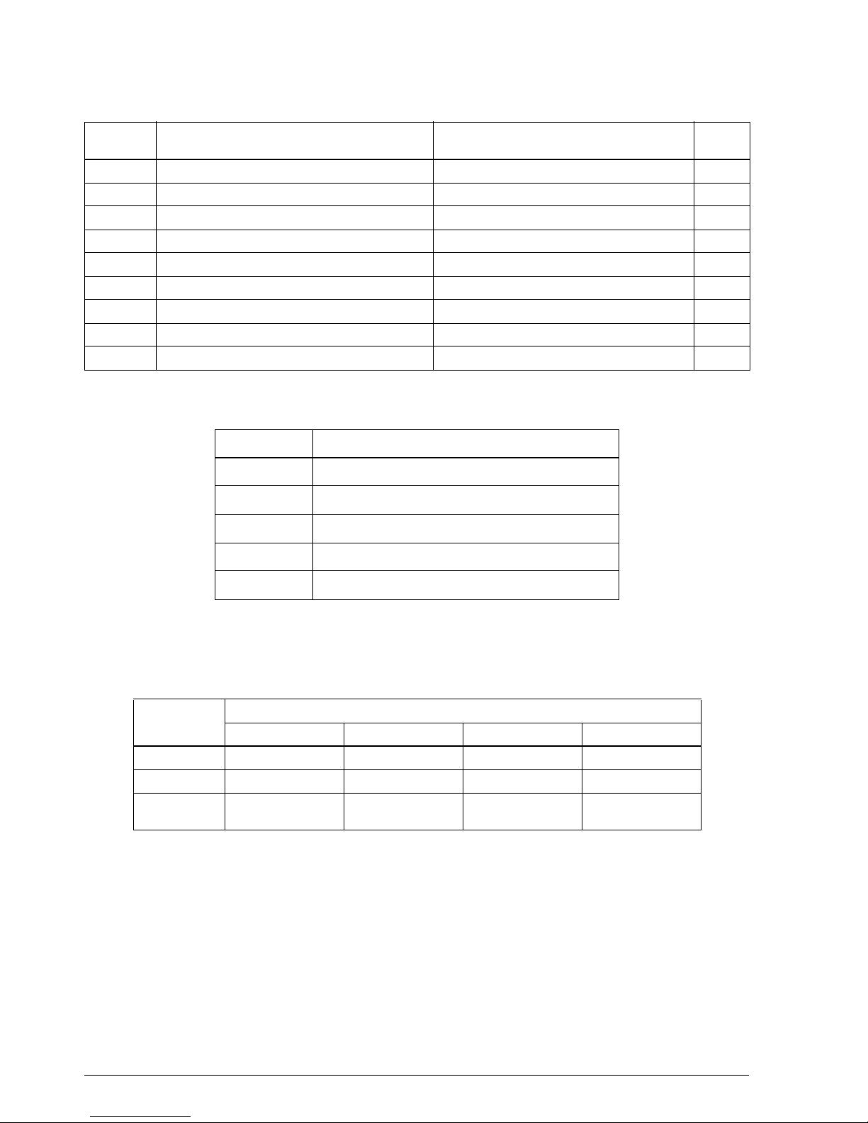
Supported Commands
Command Name Function type
Page
number
HT Horizontal tab Print position 1-20
LF Print and line feed Print 1-4
CR Print and carriage return Print 1-4
DLE EOT Real-time status transmission Status 1-27
DLE ENQ Real-time request to printer Miscellaneous function 1-34
ESC SP Set right-side character spacing Character 1-8
ESC ! Select print mode(s) Character 1-14
ESC % Select/cancel user-defined character set Character 1-9
ESC & Define user-defined characters Character 1-9
ESC
✻
Select bit-image mode Bit image 1-21
ESC – Turn underline mode on/off Character 1-15
ESC 2 Select default line spacing Line spacing 1-7
ESC 3 Set line spacing Line spacing 1-7
ESC < Return home Mechanism control 1-30
ESC = Select peripheral device Miscellaneous function 1-33
ESC ? Cancel user-defined characters Character 1-9
ESC @ Initialize printer Miscellaneous function 1-31
ESC D Set horizontal tab positions Print position 1-20
ESC E Turn emphasized mode on/off Character 1-15
ESC G Turn double-strike mode on/off Character 1-16
ESC J Print and feed paper Print 1-5
ESC K Print and reverse feed Print 1-5
ESC R Select an international character set Character 1-12
ESC U Turn unidirectional printing mode on/off Mechanism control 1-30
ESC a Select justification Print position 1-21
ESC c 3
Select paper sensor(s) to output paper-end
signals
Paper sensor 1-18
ESC c 4 Select paper sensor(s) to stop printing Paper sensor 1-18
ESC c 5 Enable/disable panel buttons Panel button 1-17
ESC d Print and feed
n
lines Print 1-6
Page 12
1-2 Command Descriptions Rev. A
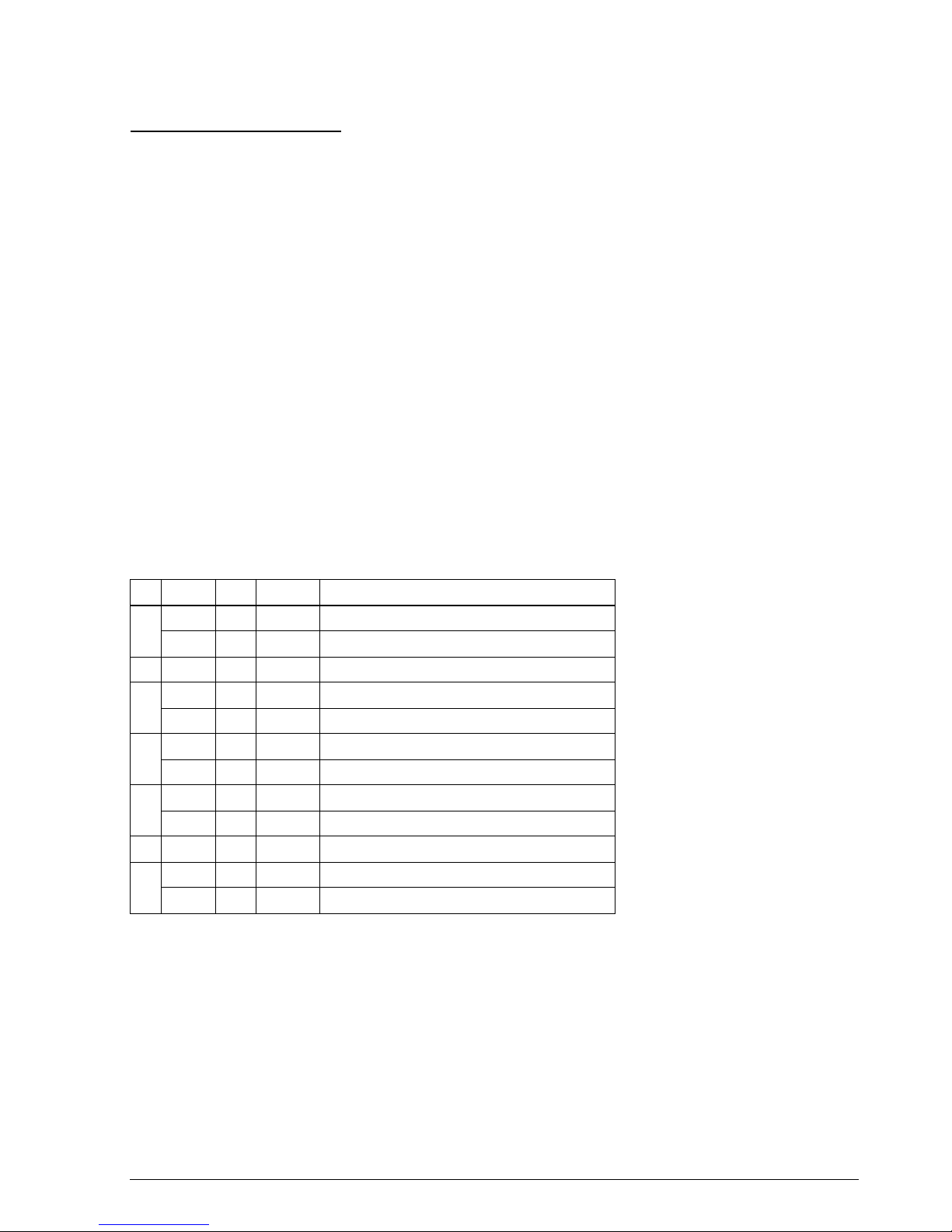
❏ The following commands are effective only when 40 bytes is selected as the receive buffer
size. The size of the receive buffer is selected by the DIP switches.
❏ Refer to the GS z 0 command for changing roll paper.
❏ The functions of these commands are different, depending on the printer models. O
indicates supported commands and X indicates unsupported (ignored) commands.
ESC e Print and reverse feed
n
lines Print 1-6
ESC p Generate pulse Miscellaneous function 1-33
ESC t Select character code table Character 1-13
ESC { Turn upside-down printing mode on/off Character 1-16
GS I Transmit printer ID Miscellaneous function 1-32
GS V Select cut mode and cut paper Mechanism control 1-30
GS a Enable/disable Automatic Status Back (ASB) Status 1-22
GS r Transmit status Status 1-26
GS z 0 On-line recovery wait time Miscellaneous function 1-35
Command Name
HT Horizontal tab
ESC % Select/cancel user-defined character set
ESC & Define user-defined characters
ESC ? Cancel user-defined characters
ESC D Set horizontal tab positions
Command
Model
TM-U200B TM-U200PB TM-U200D TM-U200PD
ESC c 3 XOXO
GS V (1) OO X X
GS V (2) OO
Only paper feed is
executed.
Only paper feed is
executed.
Command Name Function type
Page
number
Page 13
Rev. A Command Descriptions 1-3
TM–U200/U200P Information Manual
Using Bit Value Tables
For each command that has a complex method of determining the variable n, there is a table showing
how to calculate the variable in three numbering systems: binary, hexadecimal, and decimal.
When you look at the table, first find the value of each component of the variable. Then add the
values of the components together to determine the value of the variable n.
For example, here is how you would use the table below, which sets the print mode, to combine
double height, double width, and underline. In the table, you see that bit 4 on (or hex 10 or decimal
16) turns on double height, bit 5 on (or hex 20 or decimal 32) turns on double width, and bit 7 on (or
hex 80 or decimal 128) turns on underline mode.
To combine all three, turn on bits 4, 5, and 7, which is 10110000 in binary. Or you can add the hex
values 10, 20, and 80 for the hex sum of B0, or you can add the decimal values 16, 32, and 128 for the
decimal value of 176.
Therefore, you send the following to turn on double height, double width, and underline, depending
on the numbering system used:
ASCII ESC ! n
Hex 1B 21 B0
Decimal 28 33 176
Note that the program examples throughout this chapter use decimal numbers, but binary, decimal,
and hexadecimal numbers all have the same printing results.
Bit Off/On Hex Decimal Function
1
Off 00 0 Character font 9 x 9 selected.
On 01 1 Character font 7 x 9 selected.
2 — — — Undefined.
3
Off 00 0 Emphasized mode not selected.
On 08 8 Emphasized mode selected.
4
Off 00 0 Double-height mode not selected.
On 10 16 Double-height mode selected.
5
Off 00 0 Double-width mode not selected.
On 20 32 Double-width mode selected.
6 — — — Undefined.
7
Off 00 0 Underline mode not selected.
On 80 128 Underline mode selected.
Page 14

1-4 Command Descriptions Rev. A
Print Commands
The TM-U200/U200P printers support the following commands for printing characters and
advancing paper:
Command Name
LF Print and line feed
CR Print and carriage return
ESC J Print and feed paper
ESC K Print and reverse feed
ESC d Print and feed n lines
ESC e Print and reverse feed n lines
LF
[Name] Print and line feed
[Format] ASCII LF
Hex 0A
Decimal 10
LF prints the data in the print buffer and feeds one line. The amount of paper fed per line is based on
the value set using the line spacing command. The default setting is 1/6 inch.
CR
[Name] Print and carriage return
[Format] ASCII CR
Hex 0D
Decimal 13
Program Example Print Sample
PRINT #1, "AAAAA"; CHR$(&HA); AAAAA
PRINT #1, "BBBBB"; CHR$(&HA); BBBBB
Page 15

Rev. A Command Descriptions 1-5
TM–U200/U200P Information Manual
When auto line feed is enabled, CR functions in the same way as LF. When auto line feed is disabled,
CR prints the data in the print buffer and does not feed the paper. The DIP switch setting enables or
disables auto line feed. When using the serial interface, CR executes printing only.
ESC J n
[Name] Print and feed paper
[Format] ASCII ESC J n
Hex 1B 4A n
Decimal 27 74 n
[Range] 0 ≤ n ≤ 255
ESC J n prints the data in the print buffer and feeds the paper [n x (1/144)] inches. This means that the
printer can feed the paper in half-dot units. This command is used to temporarily feed a specific
length without changing the line spacing set by other commands.
ESC K n
[Name] Print and reverse feed
[Format] ASCII ESC K n
Hex 1B 4B n
Decimal 27 75 n
[Range] 0 ≤ n ≤ 48
Program Example Print Sample
PRINT #1, "AAAAA"; CHR$(&HD); AAAAA ←
Auto line feed enabled
PRINT #1, " BBBBB"; CHR$(&HA); BBBBB
AAAAABBBBB ←
Auto line feed disabled
Program Example Print Sample
PRINT #1, "AAAAA"; CHR$(&HA);
PRINT #1, "BBBBB"; CHR$(&H1B);"J";CHR$(100);
PRINT #1, "CCCCC"; CHR$(&HA);
PRINT #1, "DDDDD"; CHR$(&HA);
AAAAA
BBBBB
CCCCC
DDDDD
ESC J
used to print one line and then advance
the paper by 100/144 inch
Page 16

1-6 Command Descriptions Rev. A
ESC K n prints the data in the print buffer and feeds the paper [n × (1/144)] inches in the reverse
direction. This means that the printer can feed paper in half-dot units in the reverse direction. The
command is used to temporarily feed a specific length without changing the line spacing set by other
commands. Only the TM-U200D/PD supports this command.
ESC d n
[Name] Print and feed n lines
[Format] ASCII ESC d n
Hex 1B 64 n
Decimal 27 100 n
[Range] 0 ≤ n ≤ 255
ESC d n prints the data in the print buffer and feeds n lines. The amount of paper fed per line is based
on the value set using the line spacing command. The maximum paper feed amount is 40 inches. The
default setting of the paper feed amount is 1/6 inch.
ESC e n
[Name] Print and reverse feed n lines
[Format] ASCII ESC e n
Hex 1B 65 n
Decimal 27 101 n
[Range] 0 ≤ n ≤ 255
Program Example Print Sample
PRINT #1, "AAAAA"; CHR$(&HA);
PRINT #1, "BBBBB"; CHR$(&H1B);"K";CHR$(24);
PRINT #1, " CCCCC"; CHR$(&HA);
AAAAACCCCC
BBBBB
ESC K
used to print one line and then
reverse feed the paper by 24/144 inch
Program Example Print Sample
PRINT #1, "AAAAA"; CHR$(&HA);
PRINT #1, "BBBBB"; CHR$(&H1B);"d";CHR$(6);
PRINT #1, "CCCCC"; CHR$(&HA);
AAAAA
BBBBB
CCCCC
ESC d
used to print one line and then
advance the paper six lines
Page 17

Rev. A Command Descriptions 1-7
TM–U200/U200P Information Manual
ESC e n prints the data in the print buffer and feeds n lines in the reverse direction. The amount of
paper fed per line is based on the value set using the line spacing command. The maximum reverse
paper feed amount is 48/144 inch. The default setting of the paper feed amount is 1/6 inch. Only the
TM-U200D/PD supports this command.
Line Spacing Commands
The TM-U200/U200P printers support the following commands for setting line spacing. These
commands only set the line spacing; they do not actually advance the paper. The line spacing set
using these commands affects the results of the LF, ESC d, and ESC e commands, or when the paper
is advanced using the
PAPER FEED
button.
Command Name
ESC 2 Select default line spacing
ESC 3 Set line spacing
ESC 2
[Name] Select default line spacing
[Format] ASCII ESC 2
Hex 1B 32
Decimal 27 50
ESC 3 n
[Name] Set line spacing
[Format] ASCII ESC 3 n
Hex 1B 33 n
Decimal 27 51 n
[Range] 0 ≤ n ≤ 255
ESC 2 sets the line spacing to 1/6 inch. This is equivalent to 12 dots.
Program Example Print Sample
PRINT #1, "AAAAA"; CHR$(&HA);
PRINT #1, "BBBBB"; CHR$(&H1B);"e";CHR$(1);
PRINT #1, " CCCCC"; CHR$(&HA);
AAAAACCCCC
BBBBB
Paper reverse fed one line after
printing line of Bs
Page 18

1-8 Command Descriptions Rev. A
ESC 3 n sets the line spacing to [n × (1/144)] inches. The default setting of the paper feed amount is
1/6 inch (n=24). The line spacing can be set in half-dot units using this command.
Character Commands
The TM-U200/U200P printers support the following commands for setting character font and size.
Command Name
ESC SP Set right-side character spacing
ESC % Select/cancel user-defined character set
ESC & Define user-defined characters
ESC ? Cancel user-defined characters
ESC R Select an international character set
ESC t Select character code table
ESC ! Select print mode(s)
ESC - Turn underline mode on/off
ESC E Turn emphasized mode on/off
ESC G Turn double-strike mode on/off
ESC { Turn upside-down printing mode on/off
ESC SP n
[Name] Set right-side character spacing
[Format] ASCII ESC SP n
Hex 1B 20 n
Decimal 27 32 n
[Range] 0 ≤ n ≤ 255
Program Example Print Sample
FOR n=22 TO 32 STEP 2
PRINT #1, CHR$(&H1B);"3";CHR$(n);
←
Set line spacing
PRINT #1, "AAAAA"; CHR$(&HA);
NEXT n
PRINT #1, CHR$(&H1B);"2";
←
Set default line spacing
PRINT #1, "BBBBB"; CHR$(&HA);
PRINT #1, "CCCCC"; CHR$(&HA);
AAAAA
AAAAA
AAAAA
AAAAA
AAAAA
AAAAA
BBBBB
CCCCC
22/144-inch (11-dot) line spacing
24/144-inch (12-dot) line spacing
26/144-inch (13-dot) line spacing
28/144-inch (14-dot) line spacing
30/144-inch (15-dot) line spacing
32/144-inch (16-dot) line spacing
1/6-inch (12-dot) line spacing
Page 19

Rev. A Command Descriptions 1-9
TM–U200/U200P Information Manual
ESC SP n sets the right-side character spacing in [n × (1/160)] inches. It is used to change the spacing
between characters. The default right-side character spacing is set to 0 (n=0). This command can set
the right-side character spacing in half-dot units.
ESC % n
[Name] Select/cancel user-defined character set
[Format] ASCII ESC % n
Hex 1B 25 n
Decimal 27 37 n
[Range] 0 ≤ n ≤ 255
ESC & y c1 c2 [x1 d1 ... d(y × x1)] ... [xk d1 ... d(y × xk)]
[Name] Define user-defined characters
[Format] ASCII ESC & y c1c2[x1 d1 ... d(y × x1)] ... [xk d1 ... d(y × xk)]
Hex 1B 26
y
c1 c2 [x1 d1 ... d(y × x1)]
...
[xk d1 ... d(y × xk)]
Decimal 27 38 y c1 c2 [x1 d1 ... d(y × x1)] ... [xk d1 ... d(y
× xk)]
[Range] y = 2
32 ≤ c1 ≤ c2 ≤ 126
0 ≤ x ≤ 12 (9 × 9 font)
0 ≤ x ≤ 9 (7 × 9 font)
0 ≤ d1...d (y × x)
≤ 255
ESC ? n
[Name] Cancel user-defined characters
[Format] ASCII ESC ? n
Hex 1B 3F n
Decimal 27 63 n
[Range] 32 ≤ n ≤ 126
Program Example Print Sample
PRINT #1, CHR$(&H1B);
" ";CHR$(0);
←
Character spacing
set to 0
PRINT #1, "AAAAA"; CHR$(&HA);
PRINT #1, CHR$(&H1B);"
";CHR$(6);
←
Character spacing
set to 6
PRINT #1, "BBBBB"; CHR$(&HA);
PRINT #1, CHR$(&H1B);" ";CHR$(12);
←
Character spacing
set to 12
PRINT #1, "CCCCC"; CHR$(&HA);
AAAAA
←
0-inch right-side character spacing
BBBBB
←
6/160-inch right-side character spacing
CCCCC
←
12/160-inch right-side character spacing
Page 20

1-10 Command Descriptions Rev. A
ESC % n selects or cancels the user-defined character set. When the LSB (least significant bit) of n is 1,
the user-defined character set is selected. When it is 0, the internal character set is selected; this is the
default setting.
ESC & y c1 c2 [x1 d1 ... d(y × x1)] ... [xk d1 ... d(y × xk)] defines user-defined characters from character
code c1 to c2. y and x are the configuration of a user-defined character. y specifies the number of bytes
in the vertical direction. x specifies the number of bytes in the horizontal direction. Character code
range from ASCII code 20H (32) to 7EH (126) can be defined by c1 and c2. Up to 19 user-defined
characters can be defined. Data (d) specifies a bit printed to 1 and not printed to 0. At the default,
user-defined characters are not defined and the internal character set is printed. Once the userdefined characters have been defined, they are available until ESC @ or ESC ? is executed; the userdefined characters are redefined; the power is turned off; or the printer is reset.
Page 21

Rev. A Command Descriptions 1-11
TM–U200/U200P Information Manual
ESC ? n cancels the user-defined characters defined for the character code n. After the user-defined
characters are canceled, the internal character set is printed.
These commands are effective only when the 40 bytes receive buffer size is selected.
Program Example Print Sample
y=2
PRINT #1, CHR$ (&H1B);"&";CHR$(y);"AC";
x=7: PRINT #1, CHR$(x);
FOR i=1 TO y*x
READ d: PRINT #1, CHR$(d);
NEXT i
x=9: PRINT #1, CHR$(x);
FOR i=1 TO y*x
READ d: PRINT #1, CHR$(d);
NEXT i
x=9: PRINT #1, CHR$(x);
FOR i=1 TO 2*x
READ d: PRINT #1, CHR$(d);
NEXT i
PRINT #1, CHR$(&H1B);"%";CHR$(0); ←
Cancel
PRINT #1, "A B C D E"; CHR$(&HA);
PRINT #1, CHR$(&H1B);"%";CHR$(1);←
Select
PRINT #1, "A B C D E"; CHR$(&HA);
PRINT #1, CHR$(&H1B);"?";"A";←
Cancel user-defined
character
PRINT #1, "A B C D E"; CHR$(&HA);
ABCDE
←
Characters from internal character set
♦
◊
↑
DE
←
Characters from user-defined character set
A
◊
↑
DE
←
Characters from user-defined character set
(1 character canceled)
DATA &H30,&H00,&H78,&H00,&HFC,&H00,&H78,&H00
DATA &H30,&H00,&H00,&H00,&H00,&H00
DATA &H18,&H00,&H24,&H00,&H42,&H00,&H81,&H00
DATA &H42,&H00,&H24,&H00,&H18,&H00,&H00,&H00
DATA &H00,&H00
DATA &H18,&H00,&H28,&H00,&H4F,&H80,&H80,&H80
DATA &H4F,&H80,&H28,&H00,&H18,&H00,&H00,&H00
DATA &H00,&H00
Defines the
user-defined
characters as
"A", "B", and
"C"
Page 22

1-12 Command Descriptions Rev. A
ESC R n
[Name] Select an international character set
[Format] ASCII ESC R n
Hex 1B 52 n
Decimal 27 82 n
[Range] 0 ≤ n ≤ 10
ESC R n selects an international character set n as follows. The default value is U.S.A. (n=0).
n Country
0 U.S.A.
1 France
2 Germany
3U.K.
4 Denmark I
5Sweden
6Italy
7Spain
8 Japan
9Norway
10 Denmark II
Program Example Print Sample
FOR n=0 TO 10 # $@[ \]^` { ¦}
~
¨
n
=0 (Default setting)
PRINT #1, CHR$(&H1B);"R";CHR$(n); # $à°ç§^`éù訨
n
=1
PRINT #1, "# $ @ (\) ^ ` {¦} ~ ";CHR$(&HA); # $§ÄÖÜ ^ `äöüߨ
n
=2
NEXT n £
$@[\]^`
{ ¦ }
~
¨
n
=3
# $ @ÆØÅ^` æø å~¨
n
=4
# ¤ЙДЦЕЬйдцеь¨
n
=5
# $@°\й^щатим¨
n
=6
Pt $@¡Ñ¿^` ¨ñ}~¨
n
=7
# $@[¥]^`{¦}~¨
n
=8
# ¤ЙЖШЕЬйжшеь¨
n
=9
# $ЙЖШЕЬйжшеь¨
n
=10
Page 23

Rev. A Command Descriptions 1-13
TM–U200/U200P Information Manual
ESC t n
[Name] Select character code table
[Format] ASCII ESC t n
Hex 1B 74 n
Decimal 27 116 n
[Range] 0 ≤ n ≤ 5,
n = 254,
255
ESC t n selects a page n from the character code table as follows. The alphanumeric characters (20H
(decimal 32) to 7FH (decimal 127)) are the same for each page. The graphic characters (80H (decimal
128) to FFH (decimal 255)) are different for each page. The default setting is page 0.
n Character code table
0 Page 0 [PC437 (U.S.A., Standard Europe)]
1 Page 1 [Katakana]
2 Page 2 [PC850 (Multilingual)]
3 Page 3 [PC860 (Portuguese)]
4 Page 4 [PC863 (Canadian-French)]
5 Page 5 [PC865 (Nordic)]
254 Page 254 [Space page]
255 Page 255 [Space page]
Program Example Print Sample
PRINT #1, CHR$(&H1B);"t";CHR$(0);
←
Select page 0
GOSUB printing
PRINT #1, CHR$(&H1B);"t";CHR$(1);
←
Select page 1
GOSUB printing
END
printing:
FOR i=&H20 TO &H7F
PRINT #1, CHR$(i);
NEXT i
PRINT #1, CHR$(&HA);
FOR i=&H80 TO &HFF
PRINT #1, CHR$(i);
NEXT i
PRINT #1, CHR$(&HA);
RETURN
Page 24

1-14 Command Descriptions Rev. A
ESC ! n
[Name] Select print mode(s)
[Format] ASCII ESC ! n
Hex 1B 21 n
Decimal 27 33 n
[Range] 0 ≤ n ≤ 255
ESC ! n selects print modes using n as follows. The default character font is 7 × 9. The defaults for
other print modes are set to n=1.
Bit Off/On Hex Decimal Function
0
Off 00 0 Character font 9 x 9 selected.
On 01 1 Character font 7 x 9 selected.
1, 2 — — — Undefined.
3
Off 00 0 Emphasized mode not selected.
On 08 8 Emphasized mode selected.
4
Off 00 0 Double-height mode not selected.
On 10 16 Double-height mode selected.
5
Off 00 0 Double-width mode not selected.
On 20 32 Double-width mode selected.
6 – – – Undefined.
7
Off 00 0 Underline mode not selected.
On 80 128 Underline mode selected.
Program Example Print Sample
PRINT #1, CHR$(&H1B);"!";CHR$(0); "AA";
PRINT #1, CHR$(&H1B);"!";CHR$(8); "BB ";
PRINT #1, CHR$(&H1B);"!";CHR$(16); "CC";
PRINT #1, CHR$(&H1B);"!";CHR$(24); "DD";
PRINT #1, CHR$(&H1B);"!";CHR$(32); "EE ";
PRINT #1, CHR$(&H1B);"!";CHR$(40); "FF ";
PRINT #1, CHR$(&H1B);"!";CHR$(48); "GG";
PRINT #1, CHR$(&H1B);"!";CHR$(56); "HH";
CHR$(&HA);
AA: Normal
PRINT #1, CHR$(&H1B);"!";CHR$(129); "AA";
BB: Emphasized
PRINT #1, CHR$(&H1B);"!";CHR$(137); "BB ";
CC: Double-height
PRINT #1, CHR$(&H1B);"!";CHR$(145); "CC";
DD: Emphasized + Double-height
PRINT #1, CHR$(&H1B);"!";CHR$(153); "DD";
EE: Double-width
PRINT #1, CHR$(&H1B);"!";CHR$(161); "EE ";
FF: Emphasized + Double-width
PRINT #1, CHR$(&H1B);"!";CHR$(169); "FF ";
GG: Double-height + Double-width
PRINT #1, CHR$(&H1B);"!";CHR$(177); "GG";
HH: Emphasized + Double-height + Double-width
PRINT #1, CHR$(&H1B);"!";CHR$(185); "HH";
CHR$(&HA);
←
9 x 9 font
←
7 x 9 font
with underline
AABB
CCDD
EEFF
GGHH
AABB
CCDD
EEFF
GGHH
Page 25

Rev. A Command Descriptions 1-15
TM–U200/U200P Information Manual
ESC – n
[Name] Turn underline mode on/off
[Format] ASCII ESC – n
Hex 1B 2D
n
Decimal 27 45 n
[Range] n = 0, 1, 48, 49
ESC – n turns underline mode on or off. When n=1 or 49, underline mode is turned on, and when n=0
or 48, underline mode is turned off. The default setting is n=0.
ESC E n
[Name] Turn emphasized mode on/off
[Format] ASCII ESC E n
Hex 1B 45 n
Decimal 27 69 n
[Range] 0 ≤ n ≤ 255
ESC E n turns emphasized mode on or off. When the LSB (least significant bit) of n is 1, emphasized
mode is turned on; when it is 0, emphasized mode is turned off. The default setting is n=0.
Emphasized and double-strike printing appear the same.
Program Example Print Sample
PRINT #1, CHR$(&H1B);"-";CHR$(1);←
Select
AAAAA
←
Underline (one-dot width) turned on
PRINT #1, "AAAAA"; CHR$(&HA); BBBBB
←
Underline turned off
PRINT #1, CHR$(&H1B);"-";CHR$(0);←
Cancel
PRINT #1, "BBBBB"; CHR$(&HA);
Program Example Print Sample
PRINT #1, CHR$(&H1B);"E";CHR$(1);
←
Select
AAAAA ←
Emphasized
PRINT #1, "AAAAA"; CHR$(&HA); BBBBB ←
Normal
PRINT #1, CHR$(&H1B);"E";CHR$(0);
←
Cancel
PRINT #1, "BBBBB"; CHR$(&HA);
Page 26

1-16 Command Descriptions Rev. A
ESC G n
[Name] Turn double-strike mode on/off
[Format] ASCII ESC G n
Hex 1B 47 n
Decimal 27 71 n
[Range] 0 ≤ n ≤ 255
ESC G n turns double-strike mode on or off. When the LSB (least significant bit) of n is 1, double-
strike mode is turned on; when it is 0, double-strike mode is turned off. The default setting is n=0.
Double-strike and emphasized printing appear the same.
ESC { n
[Name] Turn upside-down printing mode on/off
[Format] ASCII ESC { n
Hex 1B 7B n
Decimal 27 123 n
[Range] 0 ≤ n ≤ 255
ESC { n turns upside-down printing mode on or off. When the LSB (least significant bit) of n is 1,
upside-down printing mode is turned on; when it is 0, upside-down printing mode is turned off. The
default setting is n=0. When upside-down mode is turned on, the printer prints 180°-rotated
characters from right to left. The line printing order is not reversed; therefore be careful of the order of
the data transmitted. This command is enabled only when input at the beginning of a line.
Program Example Print Sample
PRINT #1, CHR$(&H1B);"G";CHR$(1);
←
Select
AAAAA
←
Double-strike
PRINT #1, "AAAAA"; CHR$(&HA); BBBBB
←
Normal
PRINT #1, CHR$(&H1B);"G";CHR$(0);
←
Cancel
PRINT #1, "BBBBB"; CHR$(&HA);
Program Example Print Sample
PRINT #1, CHR$(&H1B);"{";CHR$(0);
←
Cancel
GOSUB printing
PRINT #1, CHR$(&H1B);"{";CHR$(1);
←
Select
GOSUB printing
END
printing:
PRINT #1, "ABCDE"; CHR$(&HA);
PRINT #1, "BCEDF"; CHR$(&HA);
RETURN
Normal printing
ABCDE
BCEDF
BCEDF
ABCDE
Upside-down
printing
Page 27

Rev. A Command Descriptions 1-17
TM–U200/U200P Information Manual
Panel Button Command
The TM-U200/U200P printers support the following command for enabling and disabling the panel
button (
PAPER FEED
).
Command Name
ESC c 5 Enable/disable panel button
ESC c 5 n
[Name] Enable/disable panel button
[Format] ASCII ESC c 5 n
Hex 1B 63 35 n
Decimal279953n
[Range] 0 ≤ n ≤ 255
ESC c 5 n enables or disables the
PAPER FEED
button. When the LSB (least significant bit) of n is 1,
this button is disabled; when it is 0, this button is enabled. To prevent problems caused by
accidentally pressing the
PAPER FEED
button, use this command to disable the button.
In the following cases, the panel button is enabled temporarily, regardless of the setting of this
command:
1. During the wait time set by the GS z 0 command for paper to be inserted, paper can be fed
by the
PAPER FEED
button.
2. During the recovery confirmation time, the
PAPER FEED
button is enabled, but paper cannot
be fed.
Paper Sensor Commands
The TM-U200/U200P printers support the following command for controlling the paper sensor(s)
that stop printing.
Command Name
ESC c 4 Select paper sensor(s) to stop printing
ESC c 3 Select paper sensor(s) to output paper-end signals
Program Example
PRINT #1, CHR$(&H1B);"c5";CHR$(1);
←
Disable panel button
Page 28

1-18 Command Descriptions Rev. A
ESC c 4 n
[Name] Select paper sensor(s) to stop printing
[Format] ASCII ESC c 4 n
Hex 1B 63 34 n
Decimal279952n
[Range] 0 ≤ n ≤ 255
ESC c 4 n selects the paper sensor that stops printing when the paper runs out. The default setting is
when all paper sensors are disabled (n=0). Bits 0 and 1 indicate the same sensor. If one of the bits is
enabled, the paper roll near-end sensor is selected to stop printing.
When the paper roll near-end sensor is enabled, and if the sensor detects a near-end condition during
printing, the printer stops printing and goes off-line automatically after the current printing.
Replacing a new paper roll starts the printing again (see the GS z 0 command for replacing a paper
roll).
When the paper roll near-end sensor is disabled, and if a paper near-end condition is detected during
printing, the
PAPER OUT
LED comes on, but the printer does not stop printing and does not go off-
line.
The paper roll near-end sensor is an option; therefore, if the sensor is not installed, the settings of this
command are not effective. The TM-U200/U200P printers are equipped with the paper roll sensor as
standard. The paper roll sensor is always enabled, and when a paper-end is detected, the printer
stops printing.
The paper sensor(s) used to stop printing are selected by using n as follows:
ESC c 3 n
[Name] Select paper sensor(s) to output paper-end signals
[Format] ASCII ESC c 3 n
Hex 1B 63 33 n
Decimal279951n
[Range] 0 ≤ n ≤ 255
Bit Off/On Hex Decimal Function
0,1
Off 00 0 Paper roll near-end sensor disabled.
On 01,02,03 1,2,3 Paper roll near-end sensor enabled.
2-7 — 00 0 Undefined.
Program Example
PRINT #1, CHR$(&H1B);"c4";CHR$(1);
←
Paper roll near-end sensor
Page 29

Rev. A Command Descriptions 1-19
TM–U200/U200P Information Manual
ESC c 3 n selects the paper sensor that outputs a paper-end signal to the parallel interface when a
paper-end is detected. The default setting is when all sensors are enabled (n= 15).
It is possible to select multiple sensors to output signals. Then, if any of the sensors detects a paper
end, the paper end signal is output. This command is available only with a parallel interface and is
ignored with a serial interface.
The paper near-end sensor is an option; therefore, if the sensor is not equipped, the settings of bits 0
and 1 of this command are not effective.).
Print Position Commands
The TM-U200/U200P printers support the following commands for setting the print position.
Command Name
HT Horizontal tab
ESC D Set horizontal tab positions
ESC a Select justification
Bit Off/On Hex Decimal Function
0
Off 00 0 Paper roll near-end sensor disabled.
On 01 1 Paper roll near-end sensor enabled.
1
Off 00 0 Paper roll near-end sensor disabled.
On 02 2 Paper roll near-end sensor enabled.
2
Off 00 0 Paper roll end sensor disabled.
On 04 4 Paper roll end sensor enabled.
3
Off 00 0 Paper roll end sensor disabled.
On 08 8 Paper roll end sensor enabled.
4-7 — — — Undefined.
Program Example
PRINT #1, CHR$(&H1B);"c3";CHR$(4);
←
Only paper roll end sensor enabled.
Page 30

1-20 Command Descriptions Rev. A
HT
[Name] Horizontal tab
[Format] ASCII HT
Hex 09
Decimal 10
HT moves the print position to the next horizontal tab position. This command is used to align the
character columns. The command is ignored unless the next horizontal tab position has been set.
ESC D n1...nk NUL
[Name] Set horizontal tab positions
[Format] ASCII ESC D n1...nk NUL
Hex 1B 44 n1...nk 00
Decimal 27 68 n1...nk 0
[Range] 1 ≤ n ≤ 255
0 ≤ k ≤ 32
ESC D n1...nk NUL sets the horizontal tab positions. n specifies the column number (counted from
the beginning of the line) for setting a horizontal tab position. This command deletes any previously
set horizontal tab positions. Up to 32 tab positions can be set.
The default tab positions are at intervals of 8 characters (columns 9, 17, 25, etc.) for the 7 × 9 font.
These commands are valid only when the reception buffer capacity is 40 bytes (when DIP switch 1-2
is on).
Program Example Print Sample
PRINT #1, "0123456789012345678901234567890123456";
PRINT #1, CHR$(&HA);
GOSUB ht
PRINT #1, CHR$(&H1B);"D";CHR$(10);CHR$(20);
PRINT #1, CHR$ (30);CHR$ (0);
GOSUB ht:
END
ht:
FOR i=1 TO 4
PRINT # 1, CHR$ (&H9); "H";
NEXT i
PRINT #1, CHR$ (&HA);
RETURN
0123456789012345678901234567890123456
HHHH
HHHH
8162432
Tab
position
10
Default
→
Tab
position
30
Tab
position
20
↑
↑↑
Page 31

Rev. A Command Descriptions 1-21
TM–U200/U200P Information Manual
ESC a n
[Name] Select justification
[Format] ASCII ESC a n
Hex 1B 61 n
Decimal 27 97 n
[Range] 0 ≤ n ≤ 2
48 ≤ n ≤ 50
ESC a n aligns all the data in one line to a specified position. Left justification is selected when n=0 or
48, centering is selected when n=1 or 49, and right justification is selected when n=2 or 50. The default
setting is left justification (n=0). This command is enabled only when input at the beginning of a line.
Bit-Image Command
The TM-U200/U200P printers support the following bit-image command.
Command Name
ESC
✻
Select bit-image mode
ESC ✻
m
nL nH [d]k
[Name] Select bit-image mode
[Format] ASCII ESC
✻
m
nL nH
d1...dk
Hex 1B 2A m
nL nH
d1...dk
Decimal 27 42 m
nL nH
d1...dk
[Range] m = 0, 1
0 ≤
nL
≤ 255
0 ≤
nH
≤ 3
0 ≤ d ≤ 255
k =
nL + nH ×
256
Program Example Print Sample
FOR n=0 TO 2
PRINT #1, CHR$(&H1B);"a";CHR$(n);
PRINT #1, "ABC"; CHR$(&HA);
PRINT #1, "ABCD"; CHR$(&HA);
PRINT #1, "ABCDE"; CHR$(&HA);
NEXT n
ABC
ABCD
ABCDE
ABC
ABCD
ABCDE
ABC
ABCD
ABCDE
ESC a 0
ESC a 1
ESC a 2
Page 32

1-22 Command Descriptions Rev. A
ESC
✻
m
n
L
n
H
d1...dk selects a bit-image mode using m for the number of dots specified by
(
n
L
+
n
H
×
256). d indicates the bit image data. Set a bit to 1 to print a dot, or set a bit to 0 to not print
a dot. This command is used to print a predefined picture or logo. The modes selectable by m are as
follows:
Status Commands
The TM-U200/U200P printers support the following status transmission commands. These
commands can be used to determine the status of the printer, paper sensors, and peripheral devices
connected to the printer.
Command Name
GS a Enable/disable Automatic Status Back (ASB)
GS r Transmit status
DLE EOT Transmit real-time status
GS a n
[Name] Enable/disable Automatic Status Back (ASB)
[Format] ASCII GS a n
Hex 1D 61 n
Decimal 29 97 n
[Range] 0 ≤ n ≤ 255
m
Mode
Vertical Direction Horizontal Direction
Dot Density Number of Dots Dot Density Total Number of Dots
0 8-dot single density 72 DPI 8 80 DPI 200
1 8-dot double density 72 DPI 8 160 DPI 400
Program Example Print Sample
m=0: GOSUB bitimage8
m=1: GOSUB bitimage8
END
bitimage8:
PRINT #1,
CHR$(&H1B);"
✻
";CHR$(m);CHR$(180);CHR$(0);
FOR i=1 TO 180
PRINT #1, CHR$(i);
NEXT I
PRINT #1, CHR$(&HA);
RETURN
Page 33

Rev. A Command Descriptions 1-23
TM–U200/U200P Information Manual
GS a n selects a status for ASB transmission. ASB is enabled if any status item is selected. The printer
automatically transmits a 4-byte status message whenever the status changes. Multiple status items
can be enabled or disabled. When n=0, ASB is disabled.
The default depends on the DIP switch settings (n=0 or n=2). When the printer is disabled by the
ESC = command and the ASB is enabled, the printer transmits a 4-byte status message whenever the
status changes. If the printer goes off-line due to a paper-end condition, bit 0 of the second byte
(waiting for on-line recovery) is on from the time the paper roll is inserted to the time the printer goes
on-line. See the GS z 0 command for details of on-line recovery wait time.
The paper roll near-end sensor is an option. If the printer is not equipped with the paper near-end
sensor, bits 0 and 1 of the third byte are always ON, with “Paper Adequate” status. Bit 3 of the second
byte (“Auto-Cutter Error” status) for the TM-U200D/PD is always “No Error Occurred.”
The status items are selected using n as follows:
Bit Off/On Hex Decimal Status for ASB
0
Off 00 0
Drawer kick-out connector pin 3 status
disabled.
On 01 1
Drawer kick-out connector pin 3 status
enabled.
1
Off 00 0 On-line/off-line disabled.
On 02 2 On-line/off-line enabled.
2
Off 00 0 Error status disabled.
On 04 4 Error status enabled.
3
Off 00 0 Paper roll sensor status disabled.
On 08 8 Paper roll sensor status enabled.
4-7 — — — Undefined.
Program Example
PRINT #1, CHR$(&H1D);"a";CHR$(4);
←
Enable "Error" status
Page 34

1-24 Command Descriptions Rev. A
First byte (printer information)
Second byte (error information)
Bit Off/On Hex Decimal Status for ASB
0 Off 00 0 Not used. Fixed to Off.
1 Off 00 0 Not used. Fixed to Off.
2
Off 00 0 Drawer kick-out connector pin 3 is LOW.
On 04 4 Drawer kick-out connector pin 3 is HIGH.
3
Off 00 0 On-line.
On 08 8 Off-line.
4 On 10 16 Not used. Fixed to On.
5 — — — Undefined.
6
Off 00 0
Paper is not being fed by the PAPER FEED
button.
On 40 64 Paper is being fed by the PAPER FEED button.
7 Off 00 0 Not used. Fixed to Off.
Bit Off/On Hex Decimal Status for ASB
0
Off 00 0 Not waiting for on-line recovery.
On 01 1 Waiting for on-line recovery.
1 — — — Undefined.
2
Off 00 0 No mechanical error.
On 04 4 Mechanical error has occurred.
3
Off 00 0 No auto cutter error.
On 08 8 Auto cutter error has occurred.
4 Off 00 0 Not used. Fixed to Off.
5
Off 00 0 No unrecoverable error.
On 20 32 Unrecoverable error has occurred.
6
Off 00 0
No temporary abnormality of the print head
temperature (high temperature).
On 40 64
Temporary abnormality of the print head
temperature (high temperature) has occurred.
7 Off 00 0 Not used. Fixed to Off.
Page 35

Rev. A Command Descriptions 1-25
TM–U200/U200P Information Manual
Third byte (paper sensor information)
Fourth byte (paper sensor information)
Bit Off/On Hex Decimal Status for ASB
0,1
Off 00 0 Paper near-end sensor: paper adequate.
On (03) (3) Paper near-end sensor: paper near end.
2,3
Off 00 0 Paper end sensor: paper present.
On 0C 12 Paper end sensor: paper not present.
4 Off 00 0 Not used. Fixed to Off.
5,6 — — — Undefined.
7 Off 00 0 Not used. Fixed to Off.
Bit Off/On Hex Decimal Status for ASB
0-3 — — — Undefined.
4 Off 00 0 Not used. Fixed to Off.
5,6 — — — Undefined.
7 Off 00 0 Not used. Fixed to Off.
Page 36

1-26 Command Descriptions Rev. A
GS r n
[Name] Transmit status
[Format] ASCII GS r n
Hex 1D 72 n
Decimal 29 114 n
[Range] 1 ≤ n ≤ 2
49 ≤ n ≤ 50
GS r
n transmits the status specified by n as follows: paper sensor status as 1 byte of data when n=1 or 49,
and drawer kick-out connector status when n=2 or 50. The paper present status of bits 2 and 3 for the paper
sensor status is not transmitted because the printer goes off-line when a paper-end is detected by the
paper-end sensor. The paper roll near-end sensor is an option; if the sensor is not installed, bits 0 and 1 for
the paper sensor status are always in the “Paper Adequate” status.
Paper sensor status (n=1, 49)
Drawer kick-out connector status (n=2, 50)
Program Example
PRINT #1, CHR$(&H1D);"r";CHR$(1);
←
Transmits paper sensor status
Bit Off/On Hex Decimal Status
0,1
Off 00 0 Paper near-end sensor: paper adequate.
On (03) (3) Paper near-end sensor: paper near end.
2,3
Off 00 0 Paper end sensor: paper present.
On 0C 12 Paper end sensor: paper not present.
4 Off 00 0 Not used. Fixed to Off.
5,6 — — — Undefined.
7 Off 00 0 Not used. Fixed to Off.
Bit Off/On Hex Decimal Status
0
Off 00 0 Drawer kick-out connector pin 3 is LOW.
On 01 1 Drawer kick-out connector pin 3 is HIGH.
1-3 — — — Undefined.
4 Off 00 0 Not used. Fixed to Off.
5,6 — — — Undefined.
7 Off 00 0 Not used. Fixed to Off.
Page 37

Rev. A Command Descriptions 1-27
TM–U200/U200P Information Manual
DLE EOT n
[Name] Transmit real-time status
[Format] ASCII DLE EOT n
Hex 10 04 n
Decimal 16 4 n
[Range] 1 ≤ n ≤ 4
DLE EOT n transmits the specified status in real time. This command is executed if the printer is offline, the print buffer is full, or an error occurs.
If the printer goes off-line due to a paper-end condition, bit 5 of the printer status (waiting for on-line
recovery) is on from the time the paper roll is inserted to the time the printer goes on-line. See the
GS z 0 command for details of on-line recovery wait time.
The paper roll near-end sensor is an option. If the printer is not equipped with the paper near-end
sensor, bits 2 and 3 of the paper roll sensor status will always be “Paper Adequate.” Bit 3 of the
second byte (“Auto-Cutter Error” status) for the TM-U200D/PD is always “No Error Occurred.”
n indicates the status function as follows:
n
Function
1 Transmit printer status
2 Transmit off-line status
3 Transmit error status
4 Transmit paper roll sensor status
Program Example
PRINT #1, CHR$(&H10);CHR$(&H4);CHR$(2);
←
Transmits off-line status
Page 38

1-28 Command Descriptions Rev. A
Printer status (n=1)
Off-line status (n=2)
Bit Off/On Hex Decimal Status
0 Off 00 0 Not used. Fixed to Off.
1 On 02 2 Not used. Fixed to On.
2
Off 00 0 Drawer kick-out connector pin 3 is LOW.
On 04 4 Drawer kick-out connector pin 3 is HIGH.
3
Off 00 0 On-line.
On 08 8 Off-line.
4 On 10 16 Not used. Fixed to On.
5
Off 00 0 Not waiting for on-line recovery.
On 20 32 Waiting for on-line recovery.
6 — — — Undefined.
7 Off 00 0 Not used. Fixed to Off.
Bit Off/On Hex Decimal Status
0 Off 00 0 Not used. Fixed to Off.
1 On 02 2 Not used. Fixed to On.
2 — — — Undefined.
3
Off 00 0
Paper is not being fed by the PAPER FEED
button.
On 08 8 Paper is being fed by the PAPER FEED button.
4 On 10 16 Not used. Fixed to On.
5
Off 00 0 No paper-end stop.
On 20 32 Printing stops due to paper-end.
6
Off 00 0 No error.
On 40 64 Error occurs.
7 Off 00 0 Not used. Fixed to Off.
Page 39

Rev. A Command Descriptions 1-29
TM–U200/U200P Information Manual
Error status (n=3)
Paper roll sensor status (n=4)
Mechanism Control Commands
The TM-U200/U200P printers support the following mechanism control commands.
Command Name
ESC < Return home
ESC U Turn unidirectional printing mode on/off
GS V Select cut mode and cut paper
Bit Off/On Hex Decimal Status
0 Off 00 0 Not used. Fixed to Off.
1 On 02 2 Not used. Fixed to On.
2
Off 00 0 No mechanical error.
On 04 4 Mechanical error occurred.
3
Off 00 0 No auto cutter error.
On 08 8 Auto cutter error has occurred.
4 On 10 16 Not used. Fixed to On.
5
Off 00 0 Unrecoverable error occurred.
On 20 32 Recoverable error occurred.
6
Off 00 0
No temporary abnormality of the print head
temperature (high temperature).
On 40 64
Temporary abnormality of the print head
temperature (high temperature) has occurred.
7 Off 00 0 Not used. Fixed to Off.
Bit Off/On Hex Decimal Status
0 Off 00 0 Not used. Fixed to Off.
1 On 02 2 Not used. Fixed to On.
2,3
Off 00 0 Paper near-end sensor: paper adequate.
On (0C) (12) Paper near-end sensor: paper near end.
4 On 10 16 Not used. Fixed to On.
5,6
Off 00 0 Paper end sensor: paper adequate.
On 60 96 Paper end sensor: paper not present.
7 Off 00 0 Not used. Fixed to Off.
Page 40

1-30 Command Descriptions Rev. A
ESC <
[Name] Return home
[Format] ASCII ESC <
Hex 1B 3C
Decimal 27 60
ESC < moves the print head to the home position.
ESC U n
[Name] Turn unidirectional printing mode on/off
[Format] ASCII ESC U n
Hex 1B 55 n
Decimal 27 85 n
[Range] 0 ≤ n ≤ 255
ESC U n turns unidirectional printing mode on or off. When the LSB (least significant bit) of n is 1,
unidirectional printing is turned on; when it is 0, unidirectional printing is turned off and
bidirectional printing mode is turned on. Unidirectional printing can be turned on when printing
double-height characters to ensure that the top and bottom of the characters are aligned. The default
setting is n=0.
(1) GS V m, (2) GS V m n
[Name] Select cut mode and cut paper
[Format] (1) ASCII GS V m
Hex 1D 56 m
Decimal 29 86 m
[Format] (2) ASCII GS V mn
Hex 1D 56 mn
Decimal 29 86 mn
Program Example
PRINT #1, CHR$(&H1B);"<";
Program Example
PRINT #1, CHR$(&H1B);"U";CHR$(1);
←
Unidirectional printing mode turned on
Page 41

Rev. A Command Descriptions 1-31
TM–U200/U200P Information Manual
(1) When m = 1 or 49, GS V m executes a partial cut (one point left uncut)
(2) When m = 66, GS V m n executes a partial cut (one point left uncut) after paper is fed
[cutting position (n × approximately 1/144 inch)].
When using the above commands, there is a gap between the auto-cutter position and the print
position. These commands are effective only when input at the beginning of a line.
The TM-U200D/U200PD printers are not equipped with the auto-cutter unit; therefore, the GS V m
command is ignored. The GS V m n command executes paper feeding to the manual cutting position.
Miscellaneous Function Commands
The TM-U200/U200P printers support the following miscellaneous function commands.
Command Name
ESC @ Initialize printer
GS I Transmit printer ID
ESC p Generate pulse
ESC = Select peripheral device status
DLE ENQ Real-time request to printer
GS z 0 Set on-line recovery wait time
ESC @
[Name] Initialize printer
[Format] ASCII ESC @
Hex 1B 40
Decimal 27 64
Program Example Print Sample
PRINT #1, " AAAAA"; CHR$(&HA);
PRINT #1, CHR$(&H1B);"J";CHR$(250);
PRINT #1, CHR$(&H1D);"V";CHR$(1);
←
Cut paper
PRINT #1, " BBBBB"; CHR$(&HA);
PRINT #1, CHR$(&H1D);"V";CHR$(66);CHR$(0);
←
Feed paper and cut
Partial cut (one point left uncut)
AAAAA
Paper fed to the cutting position and
BBBBB
partial cut (one point left uncut)
performed
Page 42

1-32 Command Descriptions Rev. A
ESC @ initializes the printer. All settings, including character font and line spacing settings, are
canceled.
GS I n
[Name] Transmit printer ID
[Format] ASCII GS I n
Hex 1D 49 n
Decimal 29 73 n
[Range] 1 ≤ n ≤ 3
49 ≤ n ≤ 51
GS I n transmits the printer ID specified by n below. Each printer ID consists of 1 byte of data. The
TM-U200 series of printers have the same ID, regardless of the different models. The TM-U200B and
TM-U200D can be differentiated by ID type. Type ID = 2 for the TM-U200B. Type ID = 0 for the
TM-U200D.
Program Example Print Sample
PRINT #1, CHR$(&H1B);"!";CHR$(56);
AAAAA
BBBBB
←
All settings are canceled after
ESC @
is executed
PRINT #1, "AAAAA"; CHR$(&HA);
PRINT #1, CHR$(&H1B);"@";
←
Initializes the printer
PRINT #1, "BBBBB"; CHR$(&HA);
n
Printer ID Specification ID (hexadecimal)
1, 49 Printer model ID TM-U200/U200P 0DH
2, 50 Type ID See table below. 00H or 02H
3, 51 ROM version ID Version x.xx ESC/POS Refer to current ROM version.
Program Example
PRINT #1, CHR$(&H1D);"I";CHR$(1);
←
Transmits printer ID
Page 43

Rev. A Command Descriptions 1-33
TM–U200/U200P Information Manual
Type ID (n=2 or n=50)
ESC p m t1 t2
[Name] Generate pulse
[Format] ASCII ESC p mt1t2
Hex 1B 70 mt1t2
Decimal 27 112 mt1t2
[Range] m = 0, 1, 48, 49
0 ≤
t1
≤ 255
0 ≤
t2
≤ 255
ESC p m t1 t2 sends a pulse (on time= t1 × 2 msec / off time= t2 × 2 msec) to the specified connector
pin. When m=0 or 48, the pulse is sent to drawer-kick-out connector pin 2; when m=1 or 49, the pulse
is sent to drawer-kick-out connector pin 5.
ESC = n
[Name] Select peripheral device status
[Format] ASCII ESC = n
Hex 1B 3D n
Decimal 27 61 n
[Range] 1 ≤ n ≤ 3
Bit Off/On Hex Decimal Function
0 Off 00 0 No two-byte character code.
1
Off 00 0 No auto-cutter equipped.
On 02 2 Auto cutter equipped.
2,3 — — — Undefined.
4 Off 00 0 Not used. Fixed to Off.
5, 6 — — — Undefined.
7 Off 00 0 Not used. Fixed to Off.
Program Example
PRINT #1, CHR$(&H1B);"p";CHR$(0);CHR$(25);CHR$(250);
Page 44

1-34 Command Descriptions Rev. A
ESC = n selects the device to which the host computer sends data, based on the value of n as follows:
The printer is enabled when n = 1 or n = 3. The printer is disabled when n = 2. The default setting is
n = 1 (the printer is enabled).
When the printer is disabled, it ignores all received data, with the exception of the DLE ENQ 0 and
DLE ENQ 2 commands. Also, if ASB is enabled by the GS a command, the printer transmits a 4-byte
status message whenever the status changes.
DLE ENQ n
[Name] Real-time request to printer
[Format] ASCII DLE ENQ n
Hex 10 05 n
Decimal 16 5 n
[Range] n = 0, 2
DLE ENQ n responds to a request from the host computer specified by n as shown below. This
command is also executed when the printer is disabled. When the printer stops printing due to a
paper-end condition, n = 0 is effective only when the printer is waiting for on-line recovery from the
time the paper roll is inserted to the time the printer goes on-line.
Bit Off/On Hex Decimal Function
0
Off 00 0 Printer disabled.
On 01 1 Printer enabled.
1
Off 00 0 Customer display disabled.
On 02 2 Customer display enabled.
2-7 – – – Undefined.
Program Example Print Sample
AAAAA CCCCC
PRINT #1, CHR$(&H1B);"=";CHR$(1);←
Printer enabled
PRINT #1, "AAAAA";
PRINT #1, CHR$(&H1B);"=";CHR$(0);←
Printer disabled
PRINT #1, " BBBBB";
PRINT #1, CHR$(&H1B);"=";CHR$(1);←
Printer enabled
PRINT #1, " CCCCCC"; CHR$(&HA);
Page 45

Rev. A Command Descriptions 1-35
TM–U200/U200P Information Manual
The on-line recovery wait time is confirmed by the printer status of ASB or the DLE EOT command.
n = 2 is effective only when a recoverable error occurs. The printer can recover from an error without
turning off the power. Whether an error occurs or not can be confirmed by the ASB status or the error
status of the DLE EOT command.
GS z 0 t1 t2
[Name] Set on-line recovery wait time
[Format] ASCII GS z 0 t1 t2
Hex 1D 7A 30 t1 t2
Decimal 29 122 48 t1 t2
[Range] 0 ≤
t1
≤ 255
0 ≤
t2
≤ 255
GS z 0 t1 t2 sets the on-line recovery wait time from the time a new paper roll is installed to when the
printer goes on-line. On-line recovery wait time consists of the wait time for a paper to be inserted
and the time of a recovery confirmation. This command sets the paper wait time to approximately
t1 × 0.5 seconds and the recovery confirmation time to approximately t2 × 0.5 seconds. The paper wait
time can be set within a range of 0 seconds to approximately 2 minutes. The recovery confirmation
time can be set within a range of approximately 0.5 seconds to approximately 2 minutes, or can be set
without time limitation. When setting the recovery confirmation time without a time limitation, set
t2=0 and cancel the recovery confirmation time. The paper wait time is set to 3 seconds and the
recovery confirmation time is cancelled (no time limitation) with t1=6, t2=0 as the default.
The paper wait time is within t1 × 0.5 seconds from the time the printer finishes loading the paper.
During this time, the
PAPER OUT
LED is off. Paper can be fed by pressing the
PAPER FEED
button
and the printer can be set on-line by using the DLE ENQ command.
n
Request
0 Recovers to on-line.
2 Recovers from an error after clearing the receive and print
buffers.
Program Example
PRINT #1, CHR$(&H10);CHR$(&H5);CHR$(0);
Page 46

1-36 Command Descriptions Rev. A
The recovery confirmation time is within t2 × 0.5 seconds of the end of the paper wait time. During
this time, the
PAPER OUT
LED blinks and paper cannot be fed by pressing the
PAPER FEED
button.
However, the printer can be on-line by pressing the
PAPER FEED
button. The printer will be on-line
when the recovery confirmation time ends or by using the DLE ENQ command.
The procedures for on-line recovery by pressing the
PAPER FEED
button are as follows.
Program Example
PRINT #1, CHR$(&H1D);"z0";CHR$ (10); CHR$ (60)
←
Sets the paper wait time to 5 seconds and the recovery
confirmation time to 30 seconds.
Printing stops due to a paper end. The
PAPER OUT
LED is on.
The printer starts auto-loading. The
PAPER OUT
LED is off.
The printer starts a counter for the
recovery confirmation time. The
The printer recovers on-line. The
PAPER OUT
LED is off.
PAPER OUT
LED blinks.
➀
➁
➂
➃
➄
The printer starts a counter for the
paper to be inserted. The
PAPER OUT
LED remains off.
Press the
PAPER FEED
button.
Confirm that the
PAPER OUT
LED
Close the printer cover.
➀
Open the cover, insert a new
paper roll.
Adjust the paper position while the
PAPER OUT
LED is off.
➁
blinks (if the
PAPER OUT
LED is off,
wait for it to blink).
➂
Print Status: User Operation:
Page 47

Rev. A Command Descriptions 1-37
TM–U200/U200P Information Manual
Print Status
Status ➀: → Normal operation → Not printing due to a paper-end
The printer stops printing and goes off-line when the paper roll sensor detects a paper-end, or if the
paper near-end sensor (option) is enabled by ESC c 4 and it detects a near-end.
Printer status ➁: → Not printing due to a paper-end
When the sensor detects that a paper roll is inserted, the printer starts auto-loading automatically.
Printer status ➂: → Waiting for a paper roll to be inserted (waiting for on-line recovery)
The printer is in the paper wait status after auto-loading and the
PAPER OUT
LED is off. The printer
recovery is returned to the on-line status by DLE ENQ 0.
Printer status ➃: → Recovery confirmation status (on-line recovery wait status)
After waiting for a paper roll to be inserted, the
PAPER OUT
LED blinks and the printer is in the
recovery confirmation status. In this status, the printer cannot feed the paper by the
PAPER FEED
button, but it can recover on-line by pressing this button. The printer also can recover on-line after the
recovery confirmation time, or when DLE ENQ 0 is executed.
Printer status ➄: → Normal operation
The
PAPER OUT
LED is off, the printer recovers on-line, and it executes normal processing after the
on-line recovery wait time (the printer status ➂ + ➃), when the
PAPER FEED
button is pressed during
the recovery confirmation time, or when DLE ENQ 0 is executed.
During the time from ➂ to ➃ above, bit 0 of the second byte for the ASB or bit 5 of the printer status
for the DLE EOT command is “waiting for on-line recovery”.
User Operation
Operation ➀:
When the printer stops printing due to a paper-end, open the printer cover, remove old paper roll,
and insert a new paper roll.
Operation ➁:
When paper position adjustment is needed, close the printer cover after the adjustment. If the
PAPER
OUT
LED is off, the paper can be fed by the
PAPER FEED
button. After completing paper insertion, be
sure to close the printer cover.
Operation ➂:
Make sure that the
PAPER OUT
LED is blinking. If the
PAPER OUT
LED is off, wait until it blinks.
After confirming that the
PAPER OUT
LED is blinking, press the
PAPER FEED
button.
Page 48

1-38 Command Descriptions Rev. A
Character Code Tables
SP in a table represents space.
Page 0 (PC437: U.S.A., Standard Europe) (International character set: U.S.A.)
Page 1 (Katakana)
Page 49

Rev. A Command Descriptions 1-39
TM–U200/U200P Information Manual
Page 2 (PC850: Multilingual)
Page 3 (PC860: Portuguese)
Page 50

1-40 Command Descriptions Rev. A
Page 4 (PC863: Canadian-French)
Page 5 (PC865: Nordic)
Page 51

Rev. A Command Descriptions 1-41
TM–U200/U200P Information Manual
International character set:
Using Character Code Tables
The example below uses Page 0 (PC437) (see page 1-37) to illustrate the use of the character code
tables.
You can find the character "A" in Page 0 as follows:
The decimal value for the character "A" is 65.
Follow its column straight up to find the digits.
Hexadecimal . . .4
Binary. . . . . . . . .0100
These numbers are the most significant bits of the ASCII code.
Follow its row to the left to find the digits.
Hexadecimal . . .1
Binary. . . . . . . . .0001
These numbers are the least significant bits of the ASCII code.
The combination of the numbers above is the ASCII code for character "A".
Decimal . . . . . . .65
Hexadecimal . . .41
Binary. . . . . . . . .01000001
Country
ASCII code (hexadecimal)
Hex 2324405B5C5D5E607B7C7D 7E
Dec 3536649192939496123124125126
U.S.A. # $ @
[
\
]
^` { ¦}
~
F r a n c e # $ à ° ç § ^ ` é ù è ¨
G er m an y # $ § Ä Ö Ü ^ ` ä ö ü ß
U.K. £
$@
[
\
]
^`
{ ¦ }
~
De nma rk I # $ @ Æ Ø Å ^ ` æ ø å
~
S w e d e n # ¤ É Ä Ö Å Ü é ä ö å ü
I t a l y # $ @ ° \ é ^ ù à ò è ì
S p a i n P t $ @ ¡ Ñ ¿ ^ ` ¨ ñ }
~
Japan # $ @
[
¥
]
^` { ¦}
~
N o r w a y # ¤ É Æ Ø Å Ü é æ ø å ü
D e nm a r k I I # $ É Æ Ø Å Ü é æ ø å ü
Page 52

Rev. A Application 2-1
TM–U200/200P Information Manual
Chapter 2
Application
Receipt Issuing
This section presents examples illustrating the functioning of the ESC/POS commands and an actual
print sample.
Procedure for Receipt Issuing Using the TM-U200B
Procedure Commands used Description
1. Stamp printing
ESC 3, ESC a, ESC t, ESC !,
ESC U, ESC 2, LF, CR
Specifies a print position to the center by using the ESC a
command. Changes the character code table by using
the ESC t command, and prints a stamp date in the center
of the paper roll in the unidirection. Adjusts line spacing for
a line data being continuous.
2. Print date and time
ESC a, ESC d
Specifies a print position to the left by using the ESC a
command after printing the date and time in the center of
the paper roll.
3. Print Item A
ESC t, ESC !, LF
Selects the character code table page 1 by using the
ESC t command, the 7 x 9 font by using the ESC !
command, and prints the Item A.
4. Print Item B
ESC !, ESC U, LF
Specifies double-height by using the ESC ! command, and
prints “TOTAL” in the unidirection. Cancels the doubleheight and prints in the bidirectional mode for other lines.
5. Cut paper
GS V
Feeds the paper to the cutting position and executes
cutting.
Page 53

2-2 Application Rev. A
Print Sample
Print Sample
E P S O N
Thank you
September 10, 1995 15:00
TM-U200B
TOTAL
PAID
CHANGE
$22.00
$58.00
$60.00
$2.00
Stamp
Item A
←
Cut
Item B
←
Date and Time
TM-U200D
PS-150
$21.00
$15.00
Page 54

Rev. A Application 2-3
TM–U200/200P Information Manual
Programming Example
PRINT #1, CHR$(&H1B);"@";
←
Initializes the printer
GOSUB stamp
←
Prints stamp
PRINT #1, CHR$(&H1B);"a";CHR$(1);
←
Specifies a centered printing position
PRINT #1, CHR$(&H1B);"!";CHR$(0);
←
Specifies 9 x 9 font
PRINT #1, “September 10, 1995 15:00”;
PRINT #1, CHR$(&H1B);"d";CHR$(3);
PRINT #1, CHR$(&H1B);"a";CHR$(0);
←
Selects the left print position
PRINT #1, CHR$(&H1B);"!";CHR$(1);
←
Selects 7 x 9 font
PRINT #1, "TM-U200B $22.00"; CHR$(&HA);
PRINT #1, "TM-U200D $21.00"; CHR$(&HA);
PRINT #1, "PS-150 $15.00"; CHR$(&HA);
PRINT #1, CHR$(&HA);
PRINT #1, CHR$(&H1B);”!”;CHR$(17);
←
Selects double-height mode
PRINT #1, CHR$(&H1B);”U”;CHR$(1);
←
Selects uni-directional printing
PRINT #1, "TOTAL $58.00"; CHR$(&HA);
PRINT #1, CHR$(&H1B);"U";CHR$(0);
←
Cancels uni-directional printing
PRINT #1, CHR$(&H1B);"!";CHR$(0);
← Cancels double-height mode
PRINT #1, "------------------------------"; CHR$(&HA);
PRINT #1, "PAID $60.00";CHR$(&HA);
PRINT #1, "CHANGE $ 2.00";CHR$(&HA);
PRINT #1, CHR$(&H1D);"V";CHR$(66);CHR$(0);
←
Feeds paper to the cutting position
and cuts paper
END
Stamp:
PRINT #1, CHR$(&H1B);"3";CHR$(18);
←
Sets line spacing
PRINT #1, CHR$(&H1B);"U";CHR$(1);
←
Selects uni-directional printing
PRINT #1, CHR$(&H1B);"a";CHR$(1);
←
Selects center print position
PRINT #1, CHR$(&H1B);"!";CHR$(48);
←
Selects double-height and double-width modes
For I = 1 T0 14*2
READ d$: PRINT #1, CHR$ (VAL (“&H”+d$));
NEXT I
PRINT #1, CHR$ (&H1B);”!”; CHR$ (32);
←
Cancels double-height and double-width modes
FOR I = 1 TO 19
READ d$: PRINT #1, CHR$ (VAL (“&H”+d$));
NEXT I : PRINT #1, CHR$(&HD);
Prints date and time
Item B
Item A
Prints stamp
Page 55

2-4 Application Rev. A
Programming Example (continued)
PRINT #1, CHR$ (&H1B);”!”;CHR$ (32);
←
Selects double-height mode
FOR I =1 TO 14
READ d$: PRINT #1, CHR$ (VAL (“&H”+d$));
NEXT I
PRINT #1, CHR$ (&H1B);”!”;CHR$ (48);
←
Selects double-height and double-width modes
FOR I =1 TO 14
READ d$: PRINT #1, CHR$ (VAL (“&H”+d$));
NEXT I
PRINT #1,CHR$(&HB);”U”;CHR$(0);
←
Cancels uni-directional printing
PRINT #1,CHR$(&HB);”2”;
RETURN
DATA C9, CD, CD, CD, CD, CD, CD, CD, CD, CD, CD, CD, BB, 0A
DATA BA, 20, 20, 20, 45, 50, 53, 4F, 4E, 20, 20, 20, BA, 0A
DATA B5, B6, B2, B1, B9, DE, B1, D8, B6, DE, C4, B3, BA, DE, BB, DE,
B2, CF, BD
DATA BA, 20, 20, 20, 20, 20, 20, 20, 20, 20, 20, 20, BA, 0A
DATA C8, CD, CD, CD, CD, CD, CD, CD, CD, CD, CD, CD, BC, 0A
Prints stamp
Stamp data
 Loading...