

Page 1
Describes preinstall information and recovery method.
Describes setup and installation of the product and peripherals.
Describes the utilities included in this product and how to
use them.
Describes how to control the printer and information necessary
when you develop applications.
Describes features and general specifications for the product.
Describes how to handle the product.
Describes character code tables.
Describes how to handle the product.
Describes character code tables.
Technical Reference Guide
for Linux
Product Overview
Setup
Preinstalled OS Information
Utility
Application Development Information
Handling
Appendix
M00065301
Rev. B
Page 2

Cautions
• No part of this document may be reproduced, stored in a retrieval system, or transmitted in any form
or by any means, electronic, mechanical, photocopying, recording, or otherwise, without the prior
written permission of Seiko Epson Corporation.
• The contents of this document are subject to change without notice. Please contact us for the latest
information.
• While every precaution has been taken in the preparation of this document, Seiko Epson Corporation assumes no responsibility for errors or omissions.
• Neither is any liability assumed for damages resulting from the use of the information contained
herein.
• Neither Seiko Epson Corporation nor its affiliates shall be liable to the purchaser of this product or third
parties for damages, losses, costs, or expenses incurred by the purchaser or third parties as a result of:
accident, misuse, or abuse of this product or unauthorized modifications, repairs, or alterations to this
product, or (excluding the U.S.) failure to strictly comply with Seiko Epson Corporation’s operating
and maintenance instructions.
• Seiko Epson Corporation shall not be liable against any damages or problems arising from the use of
any options or any consumable products other than those specified as Original EPSON Products or
EPSON Approved Products by Seiko Epson Corporation.
Trademarks
EPSON is a registered trademark of Seiko Epson Corporation in Japan and other countries/regions.
openSUSE is a registered trademark of SUSE LLC in the United States and other countries.
Linux is the registered trademark of Linus Torvalds in the U.S. and other countries.
Copyright © 2013 Seiko Epson Corporation. All rights reserved.
2
Page 3
For Safety
Key to Symbols
The symbols in this manual are identified by their level of importance, as defined below. Read
the following carefully before handling the product.
You must follow warnings carefully to avoid serious bodily injury.
WARNING
Provides information that must be observed to prevent damage to the equipment or loss of
data.
CAUTION
Possibility of sustaining physical injuries.
Possibility of causing physical damage.
Possibility of causing information loss.
Provides information that must be observed to avoid damage to your equipment or a
malfunction.
Provides important information and useful tips.
3
Page 4

Warnings
WARNING
To avoid risk of electric shock, do not set up this product or handle cables during
a thunderstorm.
Never insert or disconnect the power plug with wet hands.
Doing so may result in severe shock.
Handle the power cable with care.
Improper handling may lead to fire or electric shock.
Do not modify or attempt to repair the cable.
Do not place any heavy object on top of the cable.
Avoid excessive bending, twisting, and pulling.
Do not place the cable near heating equipment.
Check that the plug is clean before plugging it in.
Be sure to push the plug all the way in.
Be sure to use the specified power source.
Connection to an improper power source may cause fire or shock.
Do not place multiple loads on the power outlet.
Overloading the outlet may lead to fire or shock.
Shut down your equipment immediately if it produces smoke, a strange odor, or
unusual noise.
Continued use may lead to fire. Immediately unplug the equipment and contact your
dealer or a Seiko Epson service center for advice.
Never attempt to repair this product yourself.
Improper repair work can be dangerous.
Never disassemble or modify this product.
Tampering with this product may result in injury or fire.
Do not allow foreign matter to fall into the equipment.
Penetration by foreign objects may lead to fire.
If water or other liquid spills into this equipment, do not continue to use it.
Continued use may lead to fire. Unplug the power cord immediately and contact your
dealer or a Seiko Epson service center for advice.
Do not use aerosol sprayers containing flammable gas inside or around this
product.
Doing so may cause fire.
4
Page 5

Cautions
CAUTION
Do not connect cables in ways other than those mentioned in this manual.
Different connections may cause equipment damage or fire.
Be sure to set this equipment on a firm, stable, horizontal surface.
The product may break or cause injury if it falls.
Do not use this product in locations subject to high humidity or dust levels.
Excessive humidity and dust may cause equipment damage or fire.
Do not place heavy objects on top of this product. Never stand or lean on this
product.
Equipment may fall or collapse, causing breakage and possible injury.
Take care not to injure your fingers on the manual cutter
When you remove printed paper
When you perform other operations such as loading/replacing roll paper
Do not open the roll paper cover without taking the necessary precautions, as this
can result in injury from the autocutter fixed blade.
To ensure safety, unplug this product before leaving it unused for an extended
period.
5
Page 6
Wireless LAN (OT-WL01) Important Safety Information
May exert electromagnetic interference on, and cause malfunction of, cardiac
pacemakers.
WARNING
CAUTION
Before using this product, check that there is no one in the vicinity using a cardiac
pacemaker.
May exert electromagnetic interference on, and cause malfunction of, sensitive
medical equipment.
Before using this product, check that there is no sensitive medical equipment in the
vicinity.
Use of this product on aircraft may be restricted in some countries.
Before using this product, check that use of this product is not restricted on the aircraft.
Never attempt to repair this product yourself.
Improper repair work can be dangerous.
Never disassemble or modify this product.
Tampering with this product may result in injury or fire.
The OT-WL01 is only for indoor use.
The OT-WL01 should only be used for EPSON TM-i series and TM-DT series.
If it is installed on another device, it may result in computer failure, damage, or
malfunctions.
To comply with RF exposure compliance requirements, a distance of at least 20
cm must be maintained at all times between the antenna of OT-WL01 and people in
the vicinity.
Do not store in locations with high temperatures or high humidity.
It may in particular be damaged or deformed if left in a vehicle with the windows shut, or
placed in locations with unusually high temperatures for extended periods such as in
direct sunlight.
Do not wet the OT-WL01.
This may cause malfunctions to occur.
Do not use near microwave ovens.
Wireless communication may be interrupted by electromagnetic interference generated
by microwave ovens.
Do not drop it, subject it to shocks, or place heavy objects on it.
Wireless LAN (OT-WL01) Usage Precautions
Wireless Telegraphy Act Regulations
The following acts are prohibited by the Wireless Telegraphy Act.
•Modifying and disassembling (including the antenna)
•Removing the label of conformance
6
Page 7

Notes on Security when Using Wireless LAN
Important information on customer rights (maintaining privacy)
The advantage of using a wireless LAN over a LAN cable is that, because information is
exchanged using radio signals, you can easily connect to the network if you are within range of
the radio signals. A disadva
signals can pass through barriers such as walls, so that if security countermeasures are not
implemented in some way, problems such as the following may occur.
•Communication data can be intercepted
A third party may be able t
could obtain personal information from these transmissions such as IDs, passwords, or credit
card numbers, or they could intercept the contents of personal e-mail messages.
•Unauthorized access to the network
third party could access an individual or intra-company network without permission and
A
carry out any of the following activities.
Retrieve personal data or other secret information (information leakage)
Pose as another user and send inappropriate data (impersonation)
Overwrite the contents of intercepted data and resend it (falsification)
Introduce a computer virus which could cause data loss or system crashes (damage)
Initially, the possibility that such problems could occur through settings concerning the
security of the wireless LAN product and by using the product are decreased, because the
wireless LAN card and the access point have security measures to deal with these problems.
We recommend that you use this product
judgement and assuming full responsibility, and with your full understanding of problems
that may occur if you do not make any security settings.
ntage of this is that within a certain range, the electromagnetic
o receive wireless transmissions without authorization, and they
after making security settings using our own
Notes on Setting SSID (Service Set Identifier)
For protection of security, note the following precautions when setting the SSID.
•Change the SSID from the default setting.
•Do not set texts by which the owner can be identified as the SSID.
Notes on Setting Cryptographic Key
For protection of security, note the following precautions when setting the cryptographic key.
•Avoid using words on a dictionary as practicably as possible.
•Combine meaningless alphanumeric characters and symbols.
•Use texts consisted of at least 13 characters or more or of 20 characters or more if possible.
7
Page 8

Restriction of Use
When this product is used for applications requiring high reliability/safety, s uch as
transportation devices related to aviation, rail, marine, automotive, etc.; disaster prevention
devices; various safety devices, etc.; or functional/precision
product only after giving consideration to including fail-safes and redundancies into your
design to maintain safety and total system reliability. Be c a use this product was not intended for
use in applications requiring extremely high reliability/safety, such as aerospace equipment,
main communication equipment, nuclear power control equipment, or medical equipment
related to direct medical care, etc., please make your own judgment on this product's suitability
after a f
ull evaluation.
devices, etc., you should use this
8
Page 9

About this Manual
Aim of the Manual
This manual was created to provide information on development, design, and installation of
receipt issue systems and development and design of printer applications for developers.
Manual Content
The manual is made up of the following sections:
Chapter 1
Chapter 2
Chapter 3
Chapter 4
Chapter 5
Chapter 6
Appendix
Product Overview
Setup
Preinstalled OS Information
Utility
Application Development Information
Handling
Character Code Tables
9
Page 10

Contents
■ For Safety .............................................................................................................................. 3
Key to Symbols........................................................................................................................................3
Warnings..................................................................................................................................................4
Cautions ..................................................................................................................................................5
Wireless LAN (OT-WL01) Important Safety Information.......................................................................6
Wireless LAN (OT-WL01) Usage Precautions ........................................................................................6
■ Restriction of Use .................................................................................................................. 8
■ About this Manual................................................................................................................ 9
Aim of the Manual .................................................................................................................................9
Manual Content ..................................................................................................................................... 9
■ Contents.............................................................................................................................. 10
Product Overview ........................................................................15
■ Features............................................................................................................................... 15
System connection examples.............................................................................................................17
■ Product Configurations...................................................................................................... 21
Models ................................................................................................................................................... 21
Paper width...........................................................................................................................................21
Colors.....................................................................................................................................................21
Accessories ...........................................................................................................................................22
Related manuals ..................................................................................................................................22
Peripherals............................................................................................................................................. 22
■ Part Names and Functions ................................................................................................ 23
Control Panel ........................................................................................................................................24
Storage access LED and status LED ...................................................................................................25
Connectors ...........................................................................................................................................26
■ Printer function.................................................................................................................... 27
Error Status.............................................................................................................................................27
■ NV Memory (Non-Volatile Memory) ................................................................................ 29
■ Product Specifications....................................................................................................... 30
Power capacity to the exterior........................................................................................................... 31
Software Specifications .......................................................................................................................31
Printing Specifications..........................................................................................................................32
Character Specifications.....................................................................................................................32
Printable Area.......................................................................................................................................33
Printing and Cutting Positions.............................................................................................................. 35
Paper Specifications ............................................................................................................................36
Environmental Conditions ...................................................................................................................37
External Dimensions..............................................................................................................................38
External Dimensions (when the dedicated optional DM is installed)............................................. 39
TM-T88V-DT Dedicated AC Adapter .................................................................................................. 40
10
Page 11

■ Option Specifications.........................................................................................................41
DM-D110 (Dedicated customer display) .......................................................................................... 41
Wireless LAN Cable Set (OT-WL01)..................................................................................................... 42
Setup .............................................................................................43
■ Updating the ePOS-Device ...............................................................................................43
■ Flow of Setup.......................................................................................................................44
■ Installing the Product..........................................................................................................47
Important Notes ................................................................................................................................... 47
■ Attaching the Optional Customer Display.......................................................................47
Setting the Customer Display ............................................................................................................. 47
Attaching the Customer Display........................................................................................................ 49
■ Adjusting the Roll Paper Near-End Sensor .......................................................................50
■ Connecting the AC Adapter .............................................................................................51
■ OS Initial Settings ................................................................................................................52
■ Enabling or Disabling ePOS-Device..................................................................................54
■ Connecting to the Network ...............................................................................................55
For Ethernet Interface ......................................................................................................................... 55
For Wireless LAN Interface................................................................................................................... 59
■ Installing Drivers and Applications ...................................................................................67
Installing and Setting the Drivers ........................................................................................................ 67
Installing Applications ......................................................................................................................... 67
■ Service Startup Settings .....................................................................................................68
■ Registering Web Contents .................................................................................................69
Registering Web content .................................................................................................................... 71
■ Registering device control script files...............................................................................72
■ Connecting External Devices............................................................................................73
Connecting a Mouse and Keyboard................................................................................................ 73
Connecting a Display ......................................................................................................................... 73
Connecting a Printer ........................................................................................................................... 73
Connection POS Peripherals .............................................................................................................. 74
Connecting the Cash Drawer............................................................................................................ 75
■ Setting the Devices.............................................................................................................77
Registering a Printer............................................................................................................................. 77
Customer Display Settings .................................................................................................................. 79
Registering a Key Input Device.......................................................................................................... 80
Serial Communication Device Registration...................................................................................... 82
Registering Other Devices .................................................................................................................. 84
■ Printer Settings.....................................................................................................................85
Register Procedures............................................................................................................................. 85
11
Page 12

■ Product settings.................................................................................................................. 91
Changing the Session .......................................................................................................................... 91
Starting YaST..........................................................................................................................................91
Resolution settings ................................................................................................................................92
Changing DisplayLanguage...............................................................................................................93
Power button settings...........................................................................................................................93
Time settings..........................................................................................................................................94
Auto-mount settings.............................................................................................................................94
■ Attaching the Connector Cover ....................................................................................... 95
■ Removing the Connector Cover....................................................................................... 97
■ Attaching the Power Button Cover ................................................................................... 98
Preinstalled OS Information.........................................................99
■ openSUSE ............................................................................................................................ 99
Preinstallation information ...................................................................................................................99
Recovery ............................................................................................................................................. 100
Utility............................................................................................103
■ EPSON TMNet WebConfig ................................................................................................ 103
Starting EPSON TMNet WebConfig ...................................................................................................103
Information - Web serv settings - Current status.............................................................................. 104
Information - System settings - Network ...........................................................................................105
Information - System settings - Date Time........................................................................................ 107
Settings - Web serv settings - Startup settings..................................................................................108
Settings - Web serv settings - Printer .................................................................................................109
Settings - Web serv settings - Display................................................................................................ 110
Settings - Web serv settings - Key input device...............................................................................111
Settings - Web Serv settings - Serial communications ....................................................................112
Settings - Web Serv settings - Other.................................................................................................. 113
Settings - Web serv settings - Register/delete ................................................................................. 114
Settings - Web Serv settings - Update settings ................................................................................115
Settings - System settings - TCP/IP (Wired) ....................................................................................... 116
Settings - System settings - Wireless Setting......................................................................................117
Settings - System settings - TCP/IP (Wireless)....................................................................................118
Settings - System settings - Time Setting ........................................................................................... 119
Settings - Admin settings - Save/restore settings............................................................................. 120
Settings - Admin settings - Initialization.............................................................................................123
Settings - Admin settings - Log ..........................................................................................................124
Settings - Admin settings - Update Web service function ............................................................. 125
Settings - Admin settings - Admin information ................................................................................ 126
Settings - Admin settings - Password ................................................................................................127
■ TM-T88V Utility................................................................................................................... 128
12
Page 13

Application Development Information....................................129
■ Development Information for Each System ...................................................................129
Download........................................................................................................................................... 129
■ PC-POS System Development Information ....................................................................130
Interfaces and External Devices ...................................................................................................... 130
Linux command control.................................................................................................................... 131
Control Method for Devices ............................................................................................................. 132
ESC/POS command .......................................................................................................................... 133
■ ePOS-Device API ..............................................................................................................138
External Devices................................................................................................................................. 138
Application Information.................................................................................................................... 140
■ ePOS-Device XML.............................................................................................................141
External Devices................................................................................................................................. 141
Application Information.................................................................................................................... 143
■ Setting/Checking Modes.................................................................................................144
Self-test Mode .................................................................................................................................... 145
Hexadecimal Dumping Mode ......................................................................................................... 146
NV Graphics Print Mode ................................................................................................................... 147
Receipt Enhancement Information Print Mode............................................................................. 148
Handling .....................................................................................149
■ Turning the Power On/Off.................................................................................................149
Turning the Power On ........................................................................................................................ 149
Turning the Power Off ........................................................................................................................ 149
Forced Termination............................................................................................................................ 149
■ Printer Operation ..............................................................................................................150
Printer Reset........................................................................................................................................ 150
Setting and Replacing Roll Paper.................................................................................................... 151
Changing the Paper Width .............................................................................................................. 154
Removing Jammed Paper ............................................................................................................... 156
■ Customer Display Operation...........................................................................................158
■ Adjusting the Speaker Volume........................................................................................158
■ Cleaning the Case ...........................................................................................................159
■ Cleaning the Thermal Head ............................................................................................159
■ Connecting to External Devices .....................................................................................160
■ Preparing for Transport .....................................................................................................160
13
Page 14

Appendix....................................................................................161
■ Character Code Tables ................................................................................................... 161
Common to All Pages........................................................................................................................161
Page 0 [PC437: USA, Standard Europe]...........................................................................................162
Page 1 (Katakana).............................................................................................................................163
Page 2 (PC850: Multilingual) ............................................................................................................. 164
Page 3 (PC860: Portuguese) .............................................................................................................165
Page 4 (PC863: Canadian-French).................................................................................................. 166
Page 5 (PC865: Nordic) .....................................................................................................................167
Page 11 (PC851: Greek)....................................................................................................................168
Page 12 (PC853: Turkish) ....................................................................................................................169
Page 13 (PC857: Turkish) ....................................................................................................................170
Page 14 (PC737: Greek).........................................................................................................
Page 15 (ISO8859-7: Greek) ..............................................................................................................172
Page 16 (WPC1252) ...........................................................................................................................173
Page 17 (PC866: Cyrillic #2) .............................................................................................................. 174
Page 18 (PC852: Latin2) ....................................................................................................................175
Page 19 (PC858: Euro) ....................................................................................................................... 176
Page 20 (KU42: Thai) .......................................................................................................................... 177
Page 21 (TIS11: Thai)........................................................................................................................... 178
Page 26 (TIS18: Thai)........................................................................................................................... 179
Page 30 (TCVN-3: Vietnamese) ........................................................................................................ 180
Page 31 (TCVN-3: Vietnamese) ........................................................................................................ 181
Page 32 (PC720: Arabic)...................................................................................................................182
Page 33 (WPC775: Baltic Rim) ..........................................................................................................183
Page 34 (PC855: Cyrillic) ...................................................................................................................184
Page 35 (PC861: Icelandic) .....................................................................................................
Page 36 (PC862: Hebrew).................................................................................................................186
Page 37 (PC864: Arabic)...................................................................................................................187
Page 38 (PC869: Greek)....................................................................................................................188
Page 39 (ISO8859-2: Latin2)...............................................................................................................189
Page 40 (ISO8859-15: Latin9).............................................................................................................190
Page 41 (PC1098: Farsi) ..................................................................................................................... 191
Page 42 (PC1118: Lithuanian)........................................................................................................... 192
Page 43 (PC1119: Lithuanian)........................................................................................................... 193
Page 44 (PC1125: Ukrainian)............................................................................................................. 194
Page 45 (WPC1250: Latin 2).....................................................................................................
Page 46 (WPC1251: Cyrillic) ..............................................................................................................196
Page 47 (WPC1253: Greek)...............................................................................................................197
Page 48 (WPC1254: Turkish) ..............................................................................................................198
Page 49 (WPC1255: Hebrew)............................................................................................................199
Page 50 (WPC1256: Arabic)..............................................................................................................200
Page 51 (WPC1257: Baltic Rim) ........................................................................................................201
Page 52 (WPC1258: Vietnamese) ....................................................................................................202
Page 53 (KZ1048: Kazakhstan).......................................................................................................... 203
Page 255 (User-Defined Page)..........................................................................................................204
International Character Sets .............................................................................................................205
........... 171
.........185
.........195
14
Page 15

Chapter 1 Product Overview
Product Overview
This chapter describes features and specifications of the product.
Features
The TM-T88V-DT is a highly-functional printer that has an auxiliary storage and a Linux
controller in the thermal receipt printer TM-T88V. It can control POS peripherals such as
customer displays, TM printers, and barcode scanners. The following is its features.
•Integrated thermal receipt printer TM-T88V and controller.
•The controller has
•The OS employs Linux
•You can connect external devices with USB connections and serial connections (LCD unit with
touch panel, keyboard, MSR, etc.).
•Built-in Serial ATA storage device (SSD). You can use it with POS applications or databases.
•Equipped with 10BASE-T / 100BASE-TX / 1000BASE-T LAN communication capability as
standard. As an optional feature, it can also support wireless LAN.
•It features a dedicated option, the customer display.
•You can print directly or control POS peripherals from the Web application. (ePOS-Device
API).
•You can deploy and execute Web applications using server-side scripting (Perl or php) on the
Apache HTTP server of this product.
•If Web contents are placed on this product's Web server, you can periodically acquire the
contents from a separate server. (Automatic update of Web content)
•You can print directly and control POS peripheral equipment from a native application of iOS,
Androi
•You can use the pre-installed software required for the Thin-Client environment as the virtual
desktop / application client and printer.
d or similar system.
the PC architecture that uses IntelATOM processor.
based on openSUSE, and provides functionality as a Linux PC.
1
15
Page 16

Features of this printer
•High speed printing (300 mm/s maximum) is possible.
•Multi-tone graphic printing is possible.
•You can choose 58 mm or 80 mm for the roll paper width.
•Easy drop-in paper loading
•A maintenance counter function is supported.
• Paper-saving function is supported.
16
Page 17
Chapter 1 Product Overview
System connection examples
As shown below, you can configure various systems.
•PC-POS System (Page 17)
•Printing and controlling POS peripherals from the Web application (Page 18)
•Printing and controlling POS peripherals from an application on a tablet terminal (Page 19)
•Virtual environment client (Page 20)
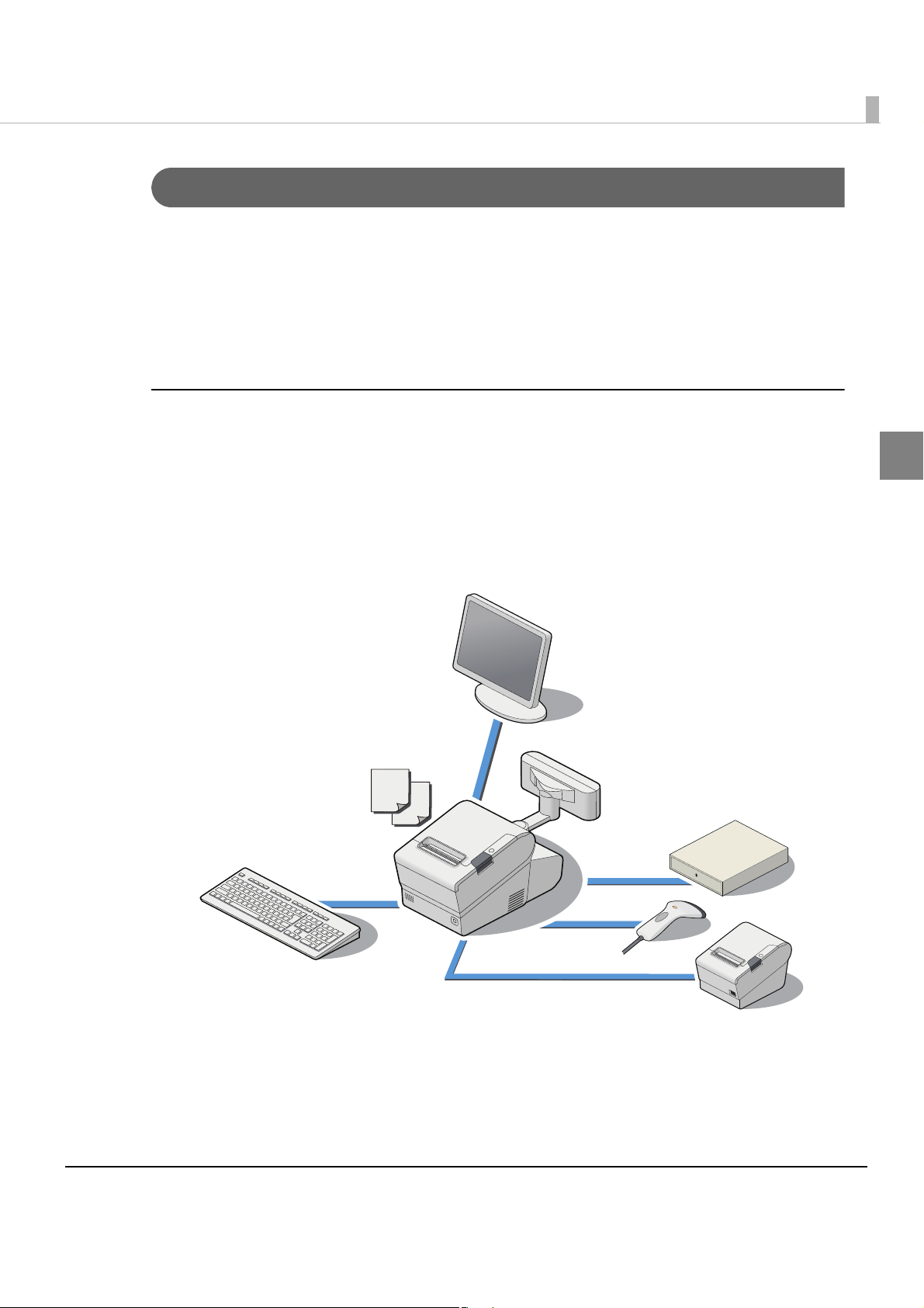
PC-POS System
Yo u can configure a simple POS system by installing POS applications and connecting a display
with a touch panel and a barcode scanner to the TM-T88V-DT.
The OS is Linux based on openSUSE. This product includes SATA SSD. You can install the
CUPS (Common Unix Printing System) driver and the JavaPOS driver.
1
Yo u can
This saves on system installation fees, saves space, and increases its maintainability.
also transfer the conventional Linux-based PC-POS system as it is.
17
Page 18
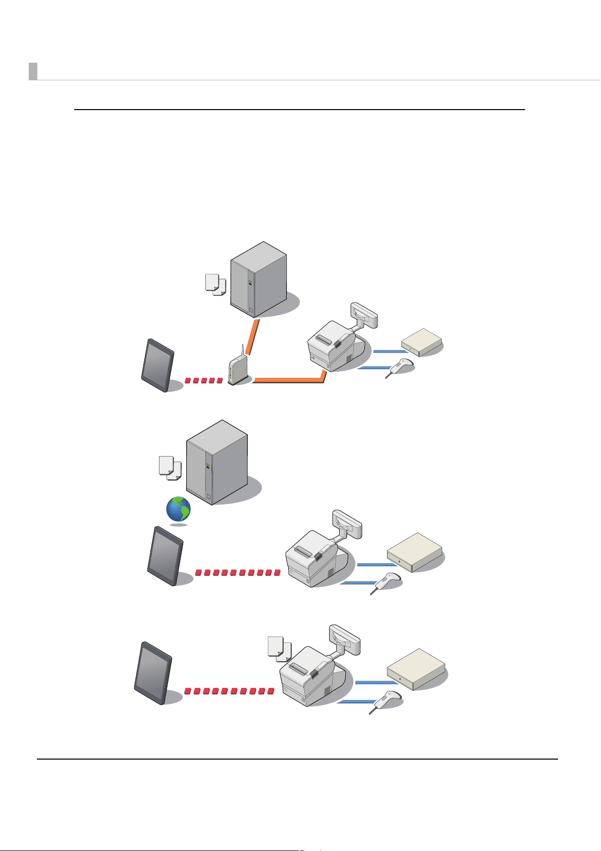
Printing and controlling POS peripherals from the Web application
ePOS-Device API is supported. You can print or control devices (display on the customer display
or input/output from the POS peripherals) from the Web application.
Yo u can control the customer display, barcode scanner, USB devices, or the serial device from the
same API system. Also, you can customize the API and send and recei
Yo u can control it from the Web browser on a computer, smart phone or tablet terminal.
•Connection example 1
•Connection example 2
ve device commands.
•Connection example 3
18
Page 19
Chapter 1 Product Overview
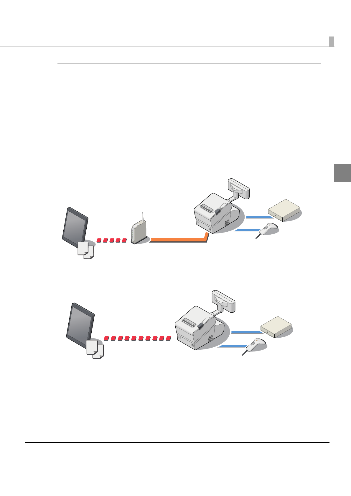
Printing and controlling POS peripherals from an application on a
tablet terminal
ePOS-DeviceXML is supported. You can print or control devices (display on the customer
display or input/output from the POS peripherals) from a tablet terminal application. You can
control the customer display, barcode scanner, USB devices or serial devices from the same
system.
Also, you can customize it and se
application on a smart phone or tablet terminal with socket communication.
If your environment allows for TCP socket communication, you can control it from your OS's
native application.
•Connection example 1
•Connecti
on example 2
nd and receive device commands. You can control it from the
1
19
Page 20
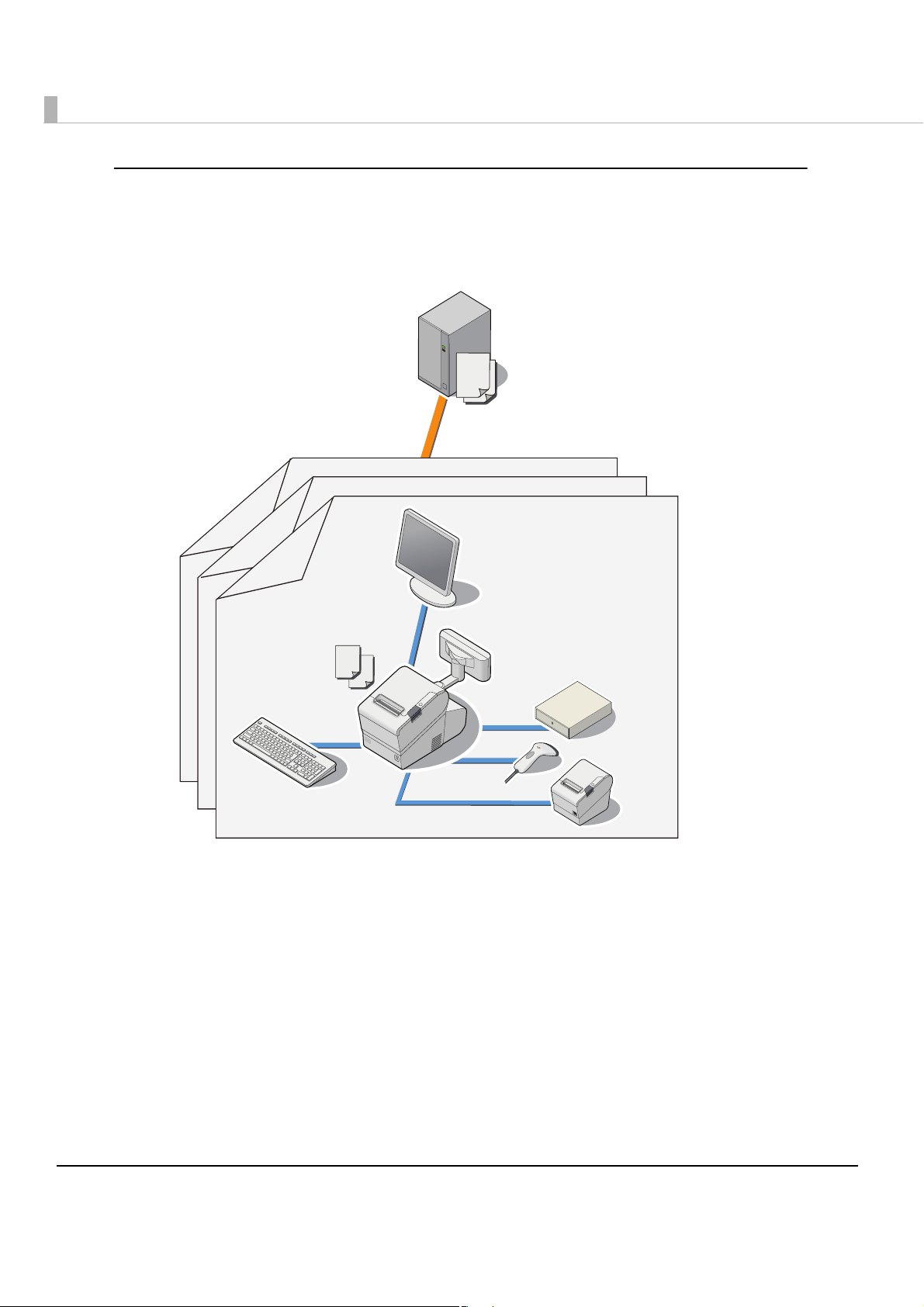
Virtual environment client
Yo u can use the product as a client of a virtual desktop or virtual application.
It supports Citrix XenServer/Client.
Printing is supported for applications that use the JavaPOS driver and CUPS driver.
20
Page 21

Chapter 1 Product Overview
Product Configurations
Models
The following models are prepared for this product. The model varies depending on the region
for sale.
CPU Main memory Auxiliary storage
Intel Atom Processor N2600 1.6GHz 2GB SATA SSD(16GB)
Paper width
• 80 m / 58 mm
Colors
•White
• Black
1
21
Page 22

Accessories
Included
•AC adapter, T (Model No. M284A)
• AC cable *1
•Connector cover
• Roll paper (for operation check)
• Roll paper guide for 58 mm width paper
•Screw x3
•Two strips for the roll paper guide
•Screw for the roll paper guide
• Recovery disc
• User’s manual
•Power button Cover
*1 May vary based on specifications and region.
Options
•Dedicated customer display (Model: DM-D110 (Dedicated Model))
•Wireless LAN cable set (Model: OT-WL01)
Related manuals
• TM-T88V-DT for Linux Technical Reference Guide (this manual)
• TM-T88V-DT User’s Manual
•ePOS-Device API User’s Manual
•ePOS-Device XML User’s Manual
•TM-DT Linux Thin-Client System Setup Guide
•TM-DT series Easy Setup Guide
For details about each system, refer to "Application Development Information" on page 129, or to
each system manual.
Peripherals
The external devices that can be connected to this product, such as POS peripherals, vary based
on the system in use. For details, refer to "Application Development Information" on page 129.
22
Page 23
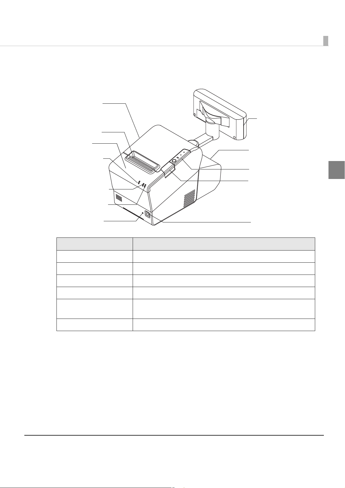
Part Names and Functions
Roll paper cover
Control panel
Cover open button
Power button
Cutter cover
Reset button
Connector cover
Manual cutter
Customer display
Status LED
(orange)
Status LED
(green)
Disk access LED
(green)
Chapter 1 Product Overview
1
Name Description
Power button Turns the product on or off.
Reset button Resets the printer unit. The controller unit is not reset.
Manual cutter A cutter for cutting the roll paper by hand.
Cover open button Opens the roll paper cover.
Cutter cover If there is a paper jam in the printer and the printer cover won't open, open
this cover, and return the cutter blade to the standard position.
Customer display (optional) Display information with your application.
23
Page 24
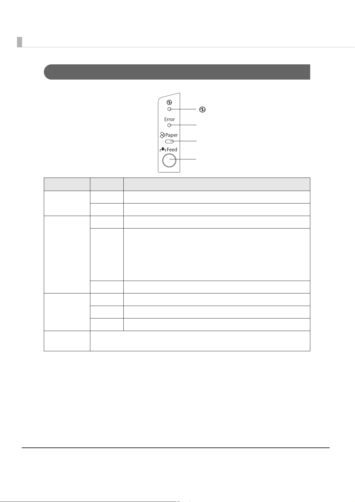
Control Panel
(Power) LED
Error LED
Paper LED
Feed button
Name Status Description
Power LED
(green)
Error LED Off Normal operation (online)
Paper LED Off There is a sufficient amount of roll paper remaining
Feed button Pressing this button once feeds the roll paper by one line. Holding this button down
On Power is being supplied
Off Power is not being supplied
On Immediately after the power is turned on or immediately after a
reset (offline).
Automatically goes off after a while to indicate that the printer is
ready.
The end of the roll paper is detected, and when printing has
stopped (offline). If this happens, replace the roll paper.
Flashing An error has occurred
On There is little or no roll paper remaining
Flashing A self-test printing standby state and macro execution standby state
feeds the roll paper continuously.
24
Page 25
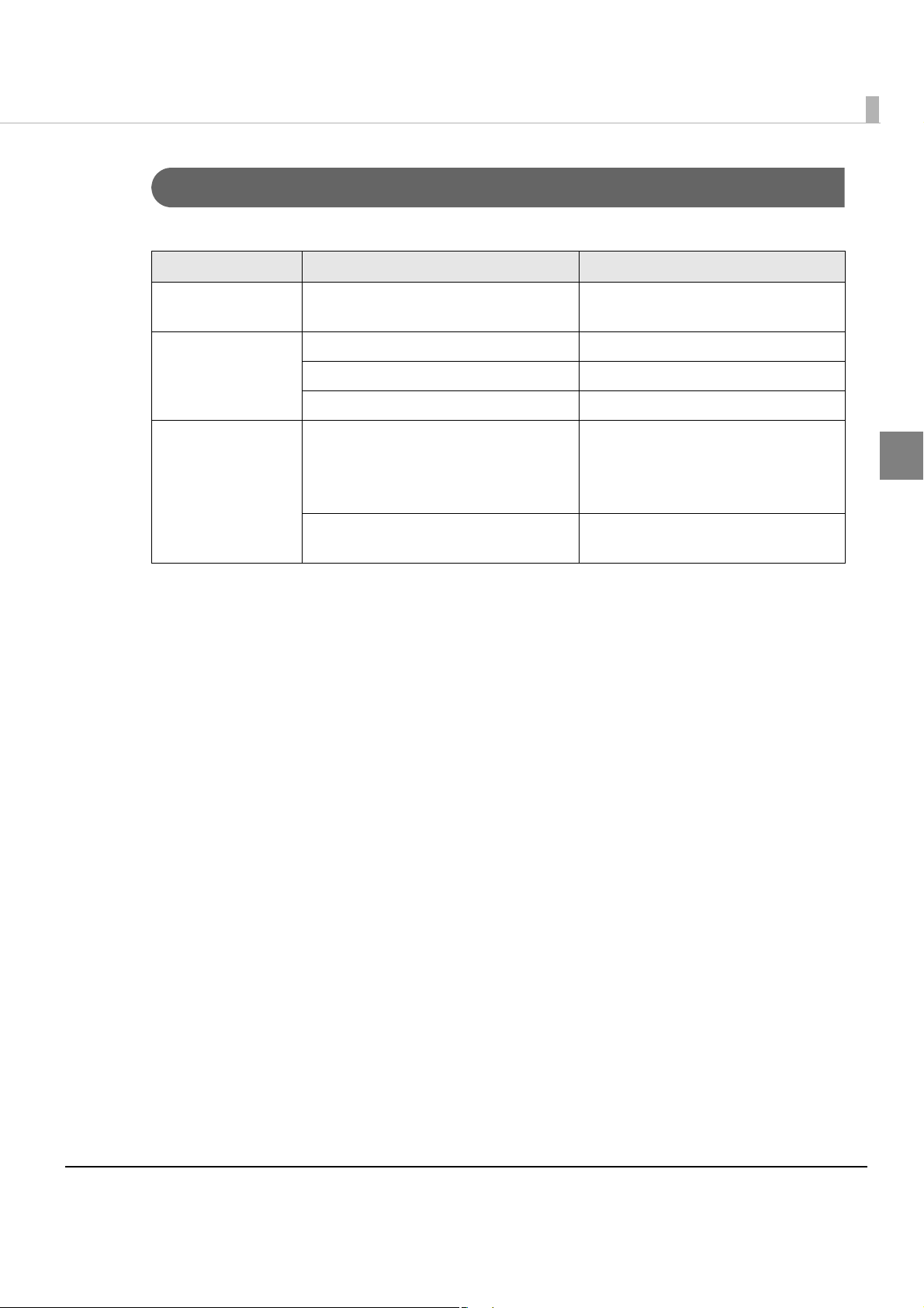
Storage access LED and status LED
These display the controller unit’s status.
Name Status Description
Chapter 1 Product Overview
Storage access LED
(Green)
Status LED (green) On Power is on
Status LED (orange) Flashing (Approx. 1 second intervals) OS start-up sequence
On Accessing the auxiliary storage
Flashing Stand-by mode
Off Power is off
Accessing the SSD; Do not turn the
power off. Doing so may result in
data loss.
Flashing (Approx. 160 millisecond
intervals)
CPU high-temperature warning
1
25
Page 26
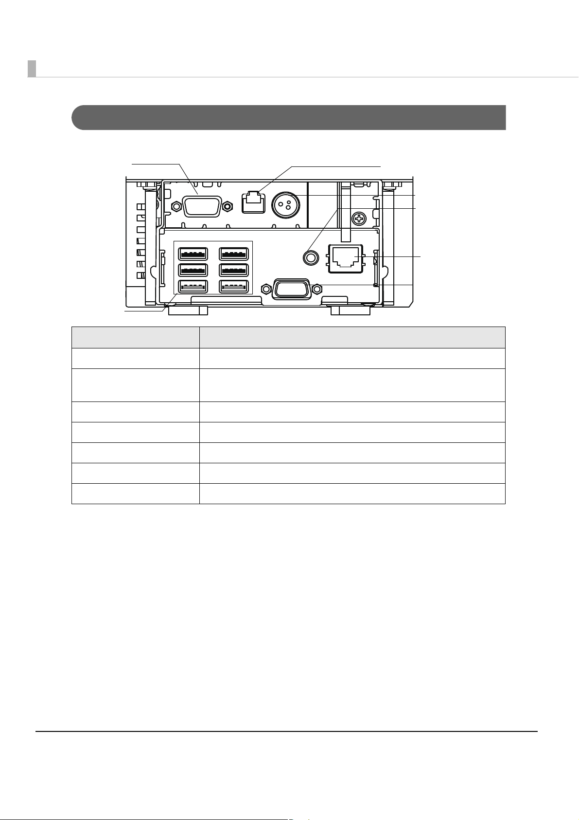
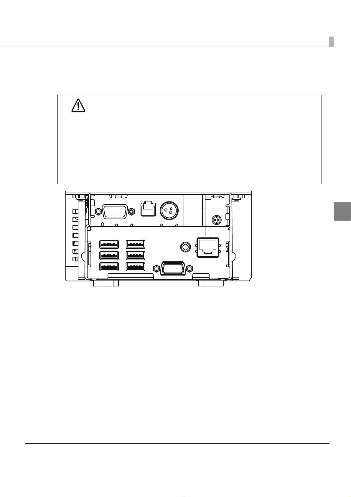
Connectors
Ethernet
connector
VGA connector
USB connector
COM connector
Drawer kick-out connector
DC input connector
Line output
connector
All the cables are connected to the connection panel on the back of the printer.
Name Description
Drawer kick-out connector Connect the cash drawer or an external optional buzzer here.
Ethernet connector Connect the LAN cable here to connect the host computer and
printer to the network.
USB connector Connect external devices with USB interface here.
DC Input connector Connect the AC adapter T, here.
VGA connector Connect the display here.
COM connector Connect a serial communication device with serial interface here.
Line output connector Connect an external speaker here.
26
Page 27
Chapter 1 Product Overview
Approx.
160 ms
Approx.
160 ms
Approx.2.56 s
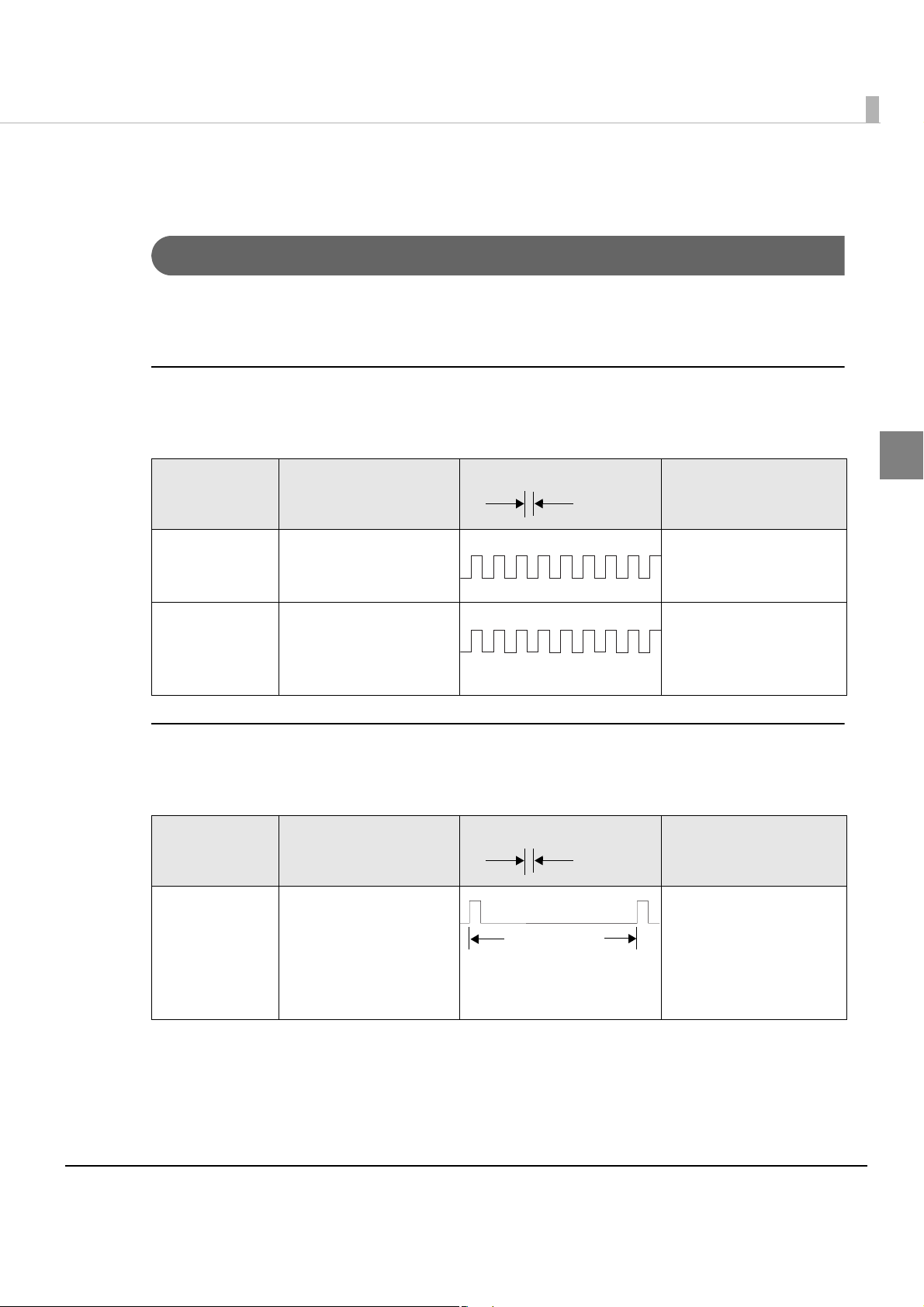
Printer function
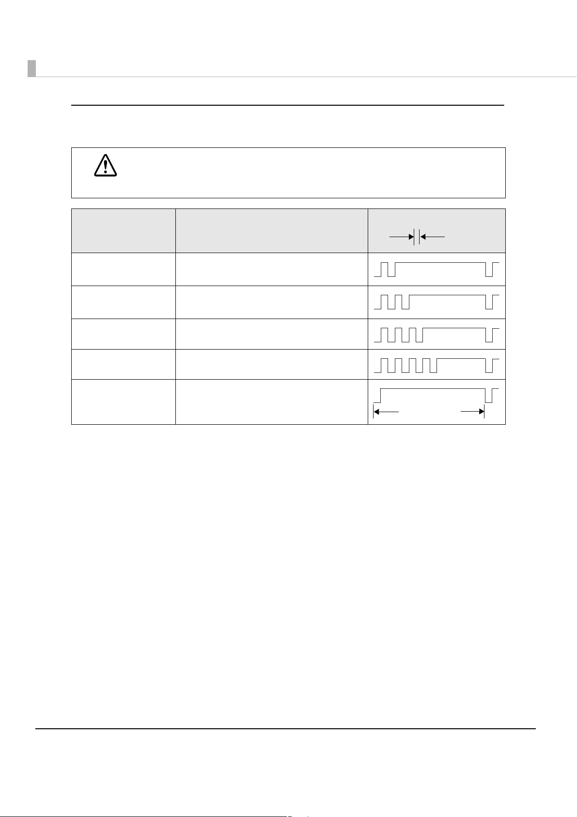
Error Status
There are three possible error types: automatically recoverable errors, recoverable errors, and
unrecoverable errors. Check the error LED flash code.
Automatically Recoverable Errors
Printing is no longer possible when automatically recoverable errors occur. The y can be
recovered easily, as described below.
Error LED flash code
Error Error description
Roll paper
cover open
error
Print head
temperature
error
The roll paper cover
was opened during
printing.
A high temperature
outside the head drive
operating range was
detected.
Recovery measure
Recovers automatically
when the roll paper
cover is closed.
Recovers automatically
when the print head
cools.
Recoverable Errors
Printing is no longer possible when recoverable errors occur. The printer recovers easily by
turning the power on again after eliminating the cause of the error.
Error LED flash code
Error Error description
Autocutter error Autocutter does not
work correctly.
Recovery measure
Remove the jammed
paper or foreign matter
in the printer, close the
roll paper cover, and
then turn the power on
to recover.
1
27
Page 28
Unrecoverable Errors
Approx.
160 ms
Approx.2.56 s
Printing is no longer possible when unrecoverable errors occur. The printer must be repaired.
Turn off the power immediately when unrecoverable errors occur.
CAUTION
Error LED flash code
Error Error description
Memory R/W error After R/W checking, the printer does not
work correctly.
High voltage error The power supply voltage is extremely
high.
Low voltage error The power supply voltage is extremely low.
CPU execution error The CPU is executing an incorrect address.
Internal circuit
connection error
Internal circuits are not connected
correctly.
28
Page 29
Chapter 1 Product Overview
NV Memory (Non-Volatile Memory)
The printer's NV memory stores data even after the printer power is turned off. NV memory
contains the following memory areas for the user:
•NV graphics memory
•Memory switches (customized value)
•User-defined page
•Maintenance counter
As a guide, NV memory rewriting should be 10 times or less a day when you program
applications.
CAUTION
NV Graphics Memory
Graphics, such as shop logos to be printed on receipts, can be stored.
1
Use the TM-T88V Utility to register graphics.
Yo u can also print and confirm the registered graphics in the NV graphics memory print mode.
For detailed information about the TM-T88V Utility, see the TM-T88V Utility User’s
Manual.
For information about how to use the NV graphics memory print mode, see "NV
Graphics Print Mode" on page 147.
User-defined Page
Yo u can store character data in the user-defined page (character code table: page 255) so that you
can also print characters not resident in the printer.
Maintenance Counter
With this function, printer information, such as the number of line feeds, the number of autocuts,
and printer operation time after the printer starts working, is automatically stored in NV
memory. You can read the information with the TM-T88V Utility or in a self-test to use
periodical checks or part replacement.
it for
29
Page 30

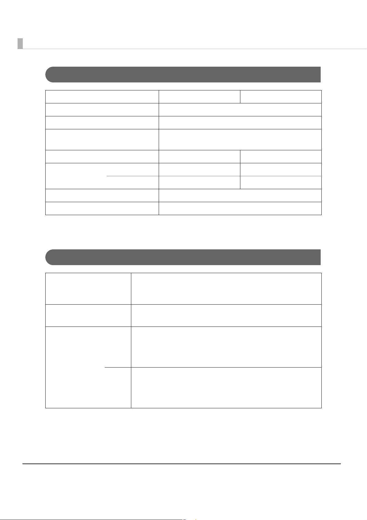
Product Specifications
Item Specifications
CPU Usable CPU Intel
Memory Main memory 2 GB, DDR3-800, SO-DIMM slot
BIOS SPI Flash 4Mbyte
Chipset Intel
Video controller On built-in CPU
Auxiliary storage SATA SSD (16GB)
Interface Ethernet 10BASE-T/100BASE-TX/1000BASE-T 1port (RJ-45)
USB External: USB 2.0 x 6 (supports high/full/low speed)
Serial External x1 (9-pin DSUB male)
VGA External x1 (15-pin DSUB female)
Drawer External x1 (RJ12 6pin)
AtomTM Processor N2600 (1MB Cache, 1.6 GHz)
NM10
Support Wake On LAN Network boot
Internal: USB 2.0 X 1 (for connecting to the printer)
Line output
(Sound
capability)
RTC/CMOS backup battery RTC is backed up by lithium battery
Speaker Internal monaural speaker
Product’s printer Thermal receipt printer at 300 mm/s on 80-mm wide roll paper
Software BIOS AMI BIOS (Supports ACPI 2.0/APM 1.2/Plug&Play)
OS Linux
Device control
software
Power specifications
(Dedicated AC adapter)
Main unit power consumption 12.2W (when not printing) / Nominal value 54W (when printing)
External dimensions 145 mm {5.71”}(W) x 279 mm {10.98”}(D) x 183 mm {7.20”}(H)
Case color White / Black
Weight (Mass)
(roll paper excluded)
Outputs sound from internal speaker
External x1 (line output)
based on openSUSE
ePOS-Device
AC100V - AC240 V / 50 Hz - 60 Hz
(only the base unit, inclusive of rear cover)
2.8 kg {6.17 lb}
(When the dedicated optional DM is installed; 3.2 kg {7.1 lb})
30
Page 31

Power capacity to the exterior
Port Power Supply capacity
USB +5 VDC 500 mA each
Chapter 1 Product Overview
Drawer
+24 VDC 1A
Software Specifications
Print control ePOS-Device API, ePOS-Device XML
(No printer driver is required.)
TM Printer, POS peripherals
control driver
Web applications Available server-side scripts:
Utility EPSON TMNet WebConfig
Controllable
printer
CUPS (Common Unix Printing System) driver
JavaPOS Version 1.13.9L
PHP ver.5.3.15
Perl ver.5.16.0
SQLite database access with the server-side script is also available
Registration of devices controlled by ePOS-Device
Registration settings for Web content
Various administrator function
Following printers with the UB-E02, UB-E03 embedded
TM-T88V
TM-T70
TM-T70II
TM-T90
TM-L90
1
Number of
printers
20 printers at maximum
31
Page 32
Printing Specifications
80 mm width paper printing 58 mm width paper printing
Printing method Thermal line printing
Dot density 180 × 180 dpi
Printing direction Unidirectional with friction feed (Reverse feed is not
supported.)
Printing width 72.0 mm (2.83"), 512 dots 50.8 mm (2.0"), 360 dots
Characters per line Font A (12 × 24) 42 30
Font B (9 × 17) 56 40
Maximum print speed*
Line spacing 4.23 mm {1/6"} (Initial setting)
dpi: dots per inch
*1: When printing with the default print density level at 24V and 25°C {77°F}.
1
300 mm/s
Character Specifications
Number of characters Alphanumeric characters: 95
Extended graphics: 128 × 43 pages (including user-defined page)
International characters: 18 sets
Character structure Font A (default): 12 × 24 (including 2-dot horizontal spacing)
Font B: 9 × 17 (including 2-dot horizontal spacing)
Character size Font A Standard: 1.41 × 3.39 mm
Double-height: 1.41 × 6.77 mm
Double-width: 2.82 × 3.39 mm
Double-width, double-height: 2.82 × 6.77 mm
Font B Standard: 0.99 × 2.40 mm
Double-height: 0.99 × 4.80 mm
Double-width: 1.98 × 2.40 mm
Double-width, double-height: 1.98 × 4.80 mm
Note:
1. Space between characters is not included.
2. Characters can be scaled up to 64 times as large as the standard size.
32
Page 33
Chapter 1 Product Overview
0.141 0.05 mm {0.0056 0.002”}
79.5 0.5 mm {3.13 0.02”}
+
-
+
-
72.2 0.2 mm {2.84 0.008}
3.7 mm {0.15} 3.7 mm {0.15}
+
-
+
-
+
-
+
-
All the numeric values are typical.
129
1
512385257
About 0.04 mm
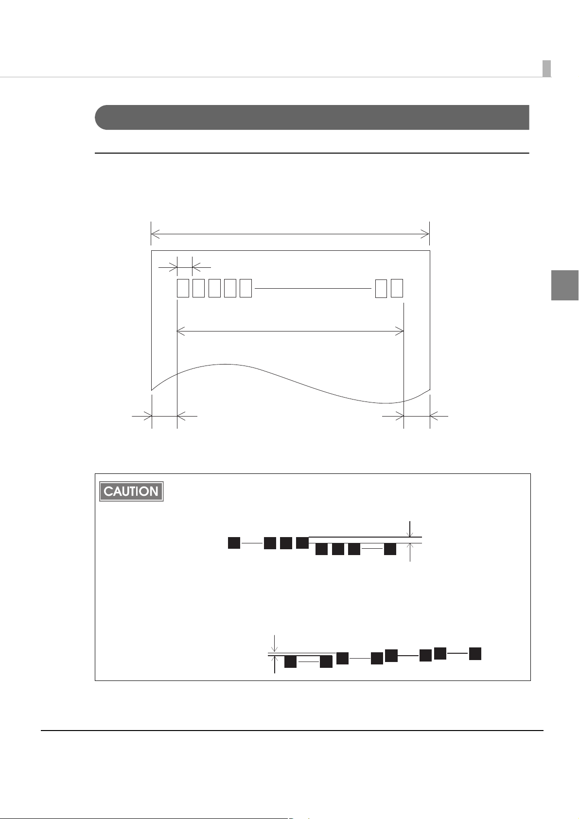
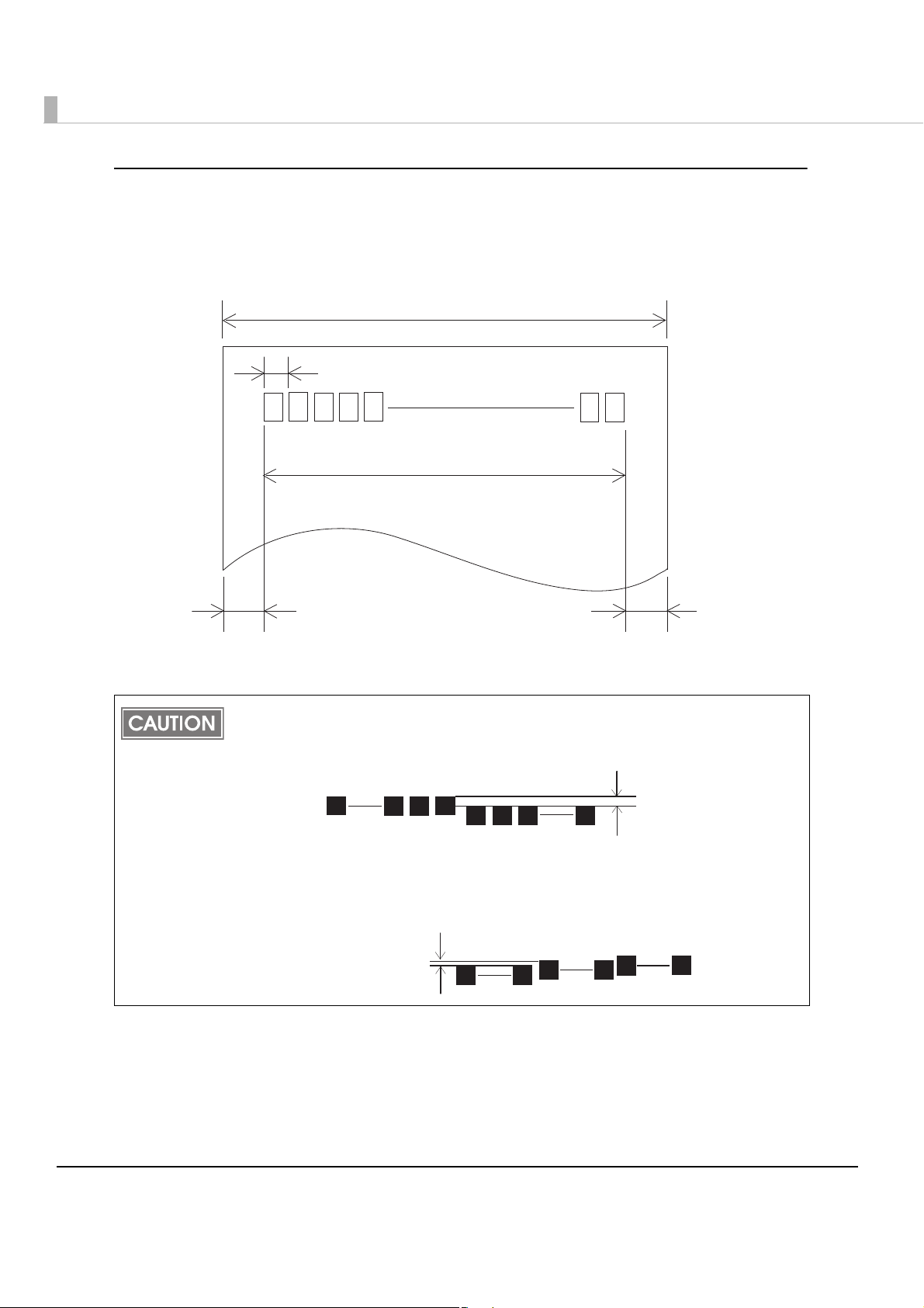
Printable Area
80 mm paper width printing
The printable area of paper with a width of 79.5 ± 0.5 mm {3.13 ± 0.02"} is 72.2 ± 0.2 mm {2.84 ±
0.008"} (512 dots), and the space on the right and left sides is approximately 3.7 mm {0.15"}.
1
In 2-divided energization, the print position within the printable area of the thermal
elements for dots 1 to 256 and 257 to 512 is shifted approximately 0.07 mm {0.0028"} in
the paper feed direction as shown in the figure below.
In 4-divided energization, the print position within the printable area of the thermal
elements for dots 1 to 128, 129 to 256, 257 to 384, and 385 to 512 is shifted
approximately 0.04 mm {0.0016"} in the paper feed direction as shown in the figure
below.
2561
About 0.07 mm
257
512
33
Page 34
58 mm paper width printing
0.141 0.05 mm {0.0056 0.002”}
57.5 0.5 mm {2.26 0.02”}
+
-
+
-
50.8 0.2 mm {2.00 0.008}
+
-
+
-
3.7 mm {0.15} 3.0 mm {0.12}
+
-
+
-
All the numeric values are typical.
129
1
360257
About 0.04 mm
The printable area of paper with a width of 57.5 ± 0.5 mm {2.26 ± 0.02"} is 50.8 ± 0.2 mm {2.00 ±
0.008"} (360 dots), and the space on the left side is approximately 3.7 mm {0.15"} and the space on
the right side is approximately 3.0 mm {0.12"}.
In 2-divided energization, the print position within the printable area of the thermal
elements for dots 1 to 256 and 257 to 360 is shifted approximately 0.07 mm {0.0028"} in
the paper feed direction as shown in the figure below.
In 4-divided energization, the print position within the printable area of the thermal
elements for dots 1 to 128, 129 to 256, and 257 to 360 is shifted approximately 0.04 mm
{0.0016"} in the paper feed direction as shown in the figure below.
2561
About 0.07 mm
257
360
34
Page 35

Printing and Cutting Positions
Autocutter blade position
Approx. 29 mm
Approx. 15mm
Manual-cutter position
Center of the print dotline
Paper feed direction
Printable area
Last line of
the previous receipt
Chapter 1 Product Overview
1
The values above may vary slightly as a result of paper slack or variations in the paper.
Take this into account when setting the cutting position of the autocutter.
35
Page 36

Paper Specifications
80 mm width paper printing 58 mm width paper printing
Paper types Specified thermal paper
Form Roll paper
Size Roll paper diameter 83 mm {3.27"} maximum
Roll paper core Inside: 12 mm {0.47"}, Outside: 18 mm {0.71"}
Roll width when taken up 80 + 0.5/-1.0 mm 58 + 0.5/-1.0 mm
Paper width 79.5 ± 0.5 mm 57.5 ± 0.5 mm
Specified roll paper type NTP080-80
TRP080-80H
Specified original paper type TF50KS-E, TF60KS-E (NIPPON Paper Industries Co., Ltd.)
PD150R, PD160R, PD190R (OJI Paper Mfg. Co., Ltd.)
P220AGB-1 (Mitsubishi Paper Mills Limited.)
P300, P310, P350 (Kanzaki Specialty Papers)
AF50KS-E (Jujo Thermal Oy)
F5041 (Mitsubishi HiTec Paper Flensburg GmbH)
KT55F20, KT48F20 (Koehler Paper Group)
Paper must not be pasted to the roll paper core.
The remaining amount of the roll paper when a roll paper near-end is detected differs
depending on the core type.
NTP058-80
TRP058-80H
36
Page 37

Environmental Conditions
[%RH]
34°C, 90%
40°C, 65%
[°C]
31°C, 90%
34°C, 75%
40°C, 43%
Specified original paper
other than above
Specified original paper:
P300, P310, P350
Chapter 1 Product Overview
Temperature/
Humidity
Acoustic noise (operating) Operating (max.): approximately 54 dB (Standing position)
Operating 5 to 40°C {41 to 113°F}, 10 to 90% RH (See the operating
temperature and humidity range below.)
Storage
(Factory packing)
-10 to 50°C {14 to 122°F}, 10 to 90% RH (except for paper)
Standby (max.): approximately 42 dB (Standing position)
Note:
The values above are measured in the Epson evaluation
condition.
Acoustic noise differs depending on the paper used, printing
contents, and the setting values, such as print speed or print
density.
1
37
Page 38

External Dimensions
[Units: mm]
•Width: Approximately 145 mm {5.71"}
•Depth: Approximately 279 mm {10.98"}
•Height: Approximately 183 mm {7.20"}
38
Page 39

Chapter 1 Product Overview
[Units: mm]
External Dimensions (when the dedicated optional DM is installed)
•Width: Approximately 177 mm {6.97"}
•Depth: Approximately 362 mm {14.25"}
•Height: Approximately 202 mm {7.95"}
1
39
Page 40
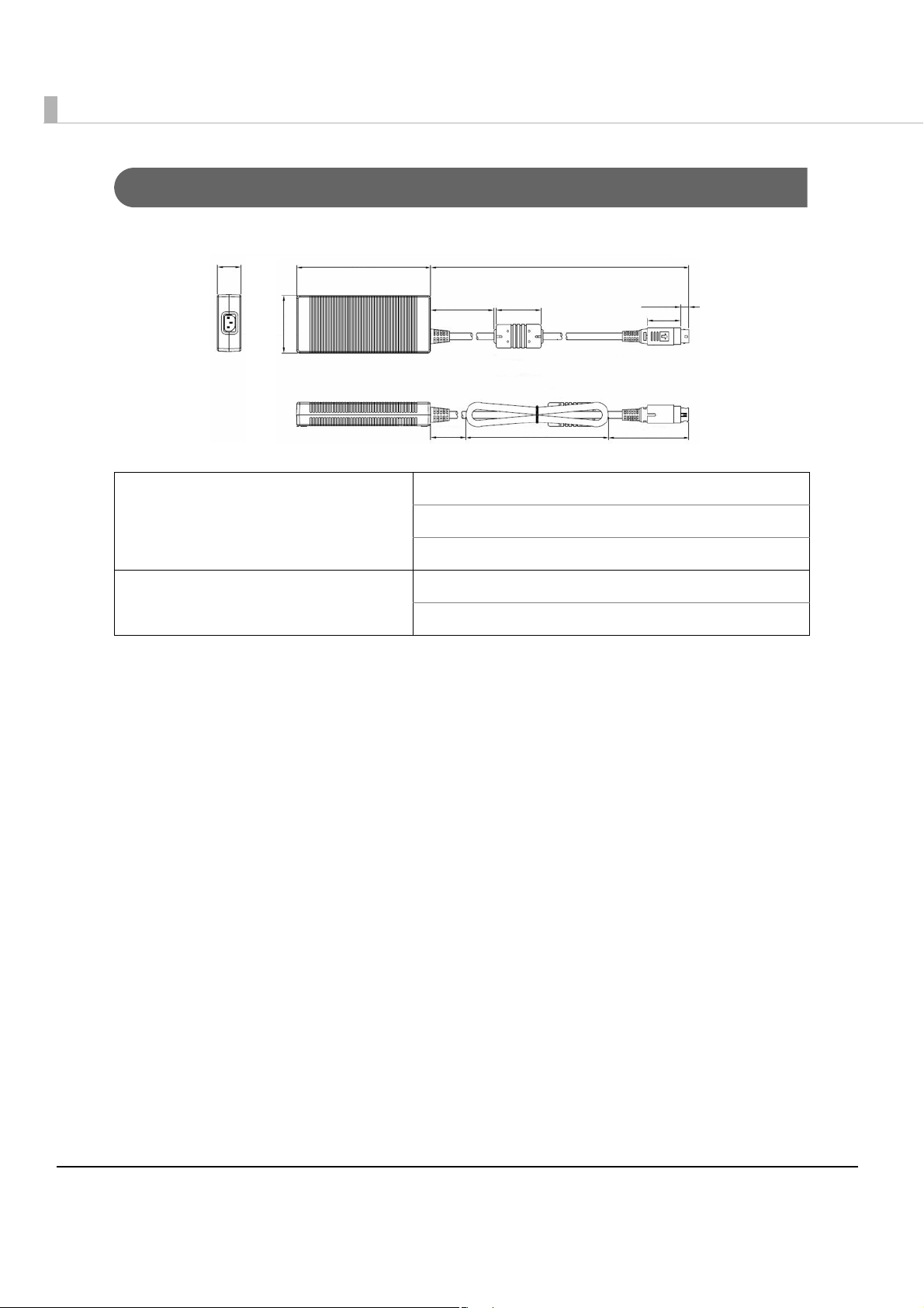
TM-T88V-DT Dedicated AC Adapter
[Units: mm]
35
200 1500
210
33.5
13
24.3
55
145
60
850
Input conditions Input voltage: AC 100V to 240V
Frequency: 50/60 Hz
Input current (rating): 2.4A
Output conditions Output voltage (rating): DC 24V ± 5%
Output current (rating): 4.2A
40
Page 41

Option Specifications
DM-D110 (Dedicated customer display)
Display format Fluorescent tube display
Displayed number of characters 40 characters (20 columns x2 lines, 5x7 dot matrix)
Display color Green (505 nm)
Chapter 1 Product Overview
Brightness 690 cd/m
Types of characters Alphanumeric characters: 95 characters
International characters: 37 characters
Graphic characters: 128 characters x12 pages
Character construction 5x7 dot matrix, cursor
Character size 3.5 x 5.0 mm
Character pitch 5.2 mm
Interface USB 2.0 Full speed
Reliability 2000 hours (Half-brightness)
Power source Voltage DC4.75 to 5.25V
Current 0.5A
External
dimensions
Weight (Mass) 0.4kg {0.9 lb }
Colors White / Black
Display 177(W) X 50.5(D) X 69(H)mm
Dimensions 177(W) X 70(D) X 130(H)mm
2
1
41
Page 42

Wireless LAN Cable Set (OT-WL01)
Wireless module ELPAP07: 802. 11b/g/n wireless LAN Module (EPSON)
Standard IEEE802.11b/g/n (Wi-Fi certificated)
SSID 1 to 32 one-byte alphanumeric characters
Connection mode Ad hoc mode, Infrastructure mode
Authentication method, Encryption
algorithm
Power voltage DC 4.5V to 5.5V
Current consumption 300 mA at maximum
Frequency range 2.4 GHz band
Potential interference range 40 m
Overall dimensions Wireless LAN unit: Approx. 24 mm × 51 mm × 10 mm (W ×
Open+WEP, Shared+WEP, WPA-PSK+TKIP, WPA-PSK+AES,
WPA2-PSK+AES, WEP64, WEP128, TKIP, AES
D × H)
USB extension cable: 1 m long
42
Page 43

Chapter 2 Setup
Setup
This chapter explains the installation and setting process for the product and external devices
necessary before using this product and the setup for each system.
•PC-POS system (page 44)
•ePOS-Device API (page 45)
•ePOS-Device XML (page 46)
Updating the ePOS-Device
Once you have updated the ePOS-Device, you can use the new ePOS-Device functions. For each
system, refer to "System connection examples" on page 17.
Confirming the ePOS-Device version
Yo u can confirm the version of the ePOS-Device on the EPSON TMNet WebConfig title bar.
2
Downloading the ePOS-Device update program
Download the following file from the Epson website and save it in your local environment.
•File name: ePOS-Device System Update Package
For more information about the update method, refer to the Readme file in the ePOS-Device
update package.
43
Page 44
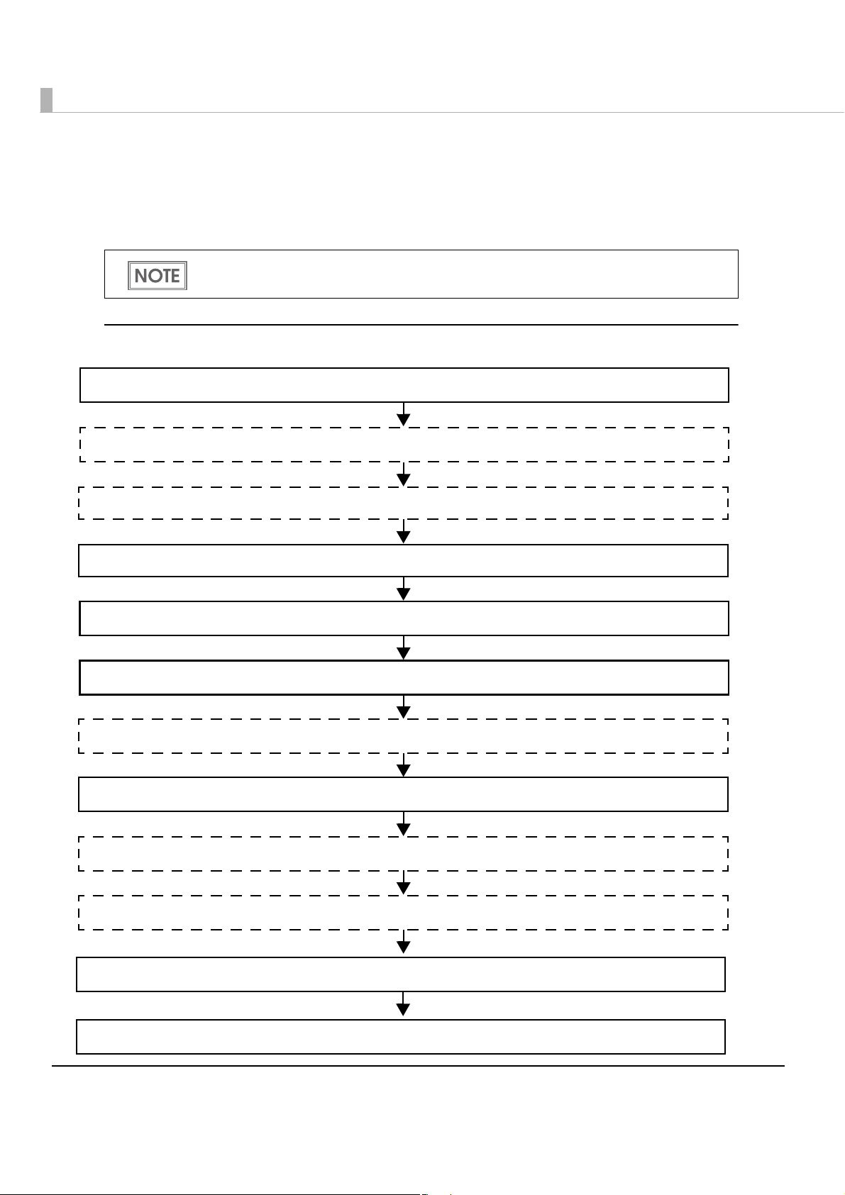
Flow of Setup
2. Attaching the Optional Customer Display (page 47)
7. Connecting to the Network (page 55)
6. Enabling or Disabling ePOS-Device (page 54)
4. Connecting the AC Adapter (page 51)
8. Installing Drivers and Applications (page 67)
3. Adjusting the Roll Paper Near-End Sensor (page 50)
5. OS Initial Settings (page 52)
1. Installing the Product (page 47)
9. Connecting External Devices (page 73)
10. Printer Settings (page 85)
11. Attaching the Connector Cover (page 95)
12. Attaching the Power Button Cover (page 98)
Setup for this product and the external devices vary depending on the system configuration
method.
In this setup flow, necessary items are in a frame with a solid line. Optional items are
explained in an frame with a dotted line.
PC-POS System
44
Page 45

If using ePOS-Device API (Controlling the printing and external
2. Attaching the Optional Customer Display (page 47)
7. Service Startup Settings (page 68)
6. Connecting to the Network (page 55)
4. Connecting the AC Adapter (page 51)
8. Registering Web content (page 71)
3. Adjusting the Roll Paper Near-End Sensor (page 50)
5. OS Initial Settings (page 52)
1. Installing the Product (page 47)
9. Registering device control script files (page 72)
10. Connecting External Devices (page 73)
11. Setting the Devices (page 77)
12. Printer Settings (page 85)
13. Attaching the Connector Cover (page 95)
14. Attaching the Power Button Cover (page 98)
devices from a Web application)
Chapter 2 Setup
2
45
Page 46

If using ePOS-Device XML (Controlling the printing and external
2. Attaching the Optional Customer Display (page 47)
7. Service Startup Settings (page 68)
6. Connecting to the Network (page 55)
4. Connecting the AC Adapter (page 51)
8. Registering device control script files (page 72)
3. Adjusting the Roll Paper Near-End Sensor (page 50)
5. OS Initial Settings (page 52)
1. Installing the Product (page 47)
9. Connecting External Devices (page 73)
10. Setting the Devices (page 77)
11. Printer Settings (page 85)
12. Attaching the Connector Cover (page 95)
13. Attaching the Power Button Cover (page 98)
devices from a terminal application)
46
Page 47

Installing the Product
Important Notes
•The Product must be installed horizontally on a flat surface (not tilted).
•Do not place the printer in dusty locations.
•Do not knock or strike the Product. This may cause defective print.
•Do not catch cables and do not place foreign matter under the printer.
Attaching the Optional Customer Display
Setting the Customer Display
DM-D110 (dedicated model) has the DIP switches. The functions are as follows.
•Displaying self-test
Chapter 2 Setup
2
•Setting the communication speed (Serial communication)
In normal use, you do not need to change the settings. If you change this setting, please match
the setting to that of the product. When used in ePOS-Device API / XML, yo
EPSON TMNet WebConfig.
u need to set with
DIP Switch Functions
Remove the USB cable from the computer and remove the cover of the dip switch. If the
USB cable is still connected to the computer during operation, this product may break
down due to short circuit, etc.
If you open the DIP switch cover, be sure to close the cover after setting the DIP switch.
When used without the cover, it may cause a malfunction.
DSW No. Function ON OFF Default
1-1 Received Error Data Ignore Displays “?” OFF
1-2 Receive Data Length 7bit 8bit OFF
1-3 Parity With Parity No Parity OFF
1-4 Parity Selection Even Odd OFF
47
Page 48
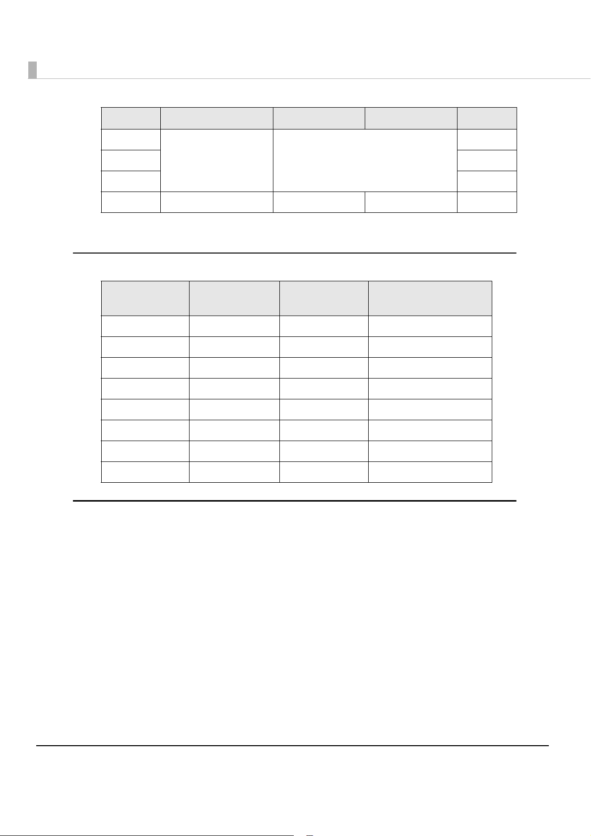
DSW No. Function ON OFF Default
1-5
1-6 OFF
1-7 ON
1-8 Execution of Self-Test *1 Yes No OFF
*1
: Executes the self-test once only when the power is tuned on.
Communication Speed
Switching
Refer to " Communication Speed
Switching"
Communication Speed Switching
SW1-5 SW1-6 SW1-7
ON ON ON 2400
OFF ON ON 4800
ON OFF ON 9600
OFF OFF ON 19200
ON ON OFF 38400
ON
Communication Speed
(bps)
OFF ON OFF 57600
ON OFF OFF 115200
OFF OFF OFF (Reserved)
How to set the DIP switch
Disconnect the cable connecting the DM-D110 (dedicated model).
1
Remove the DIP switch cover.
2
Switch the switch with something pointy.
3
Close the DIP switch cover.
4
48
Page 49
Chapter 2 Setup
❷
❶
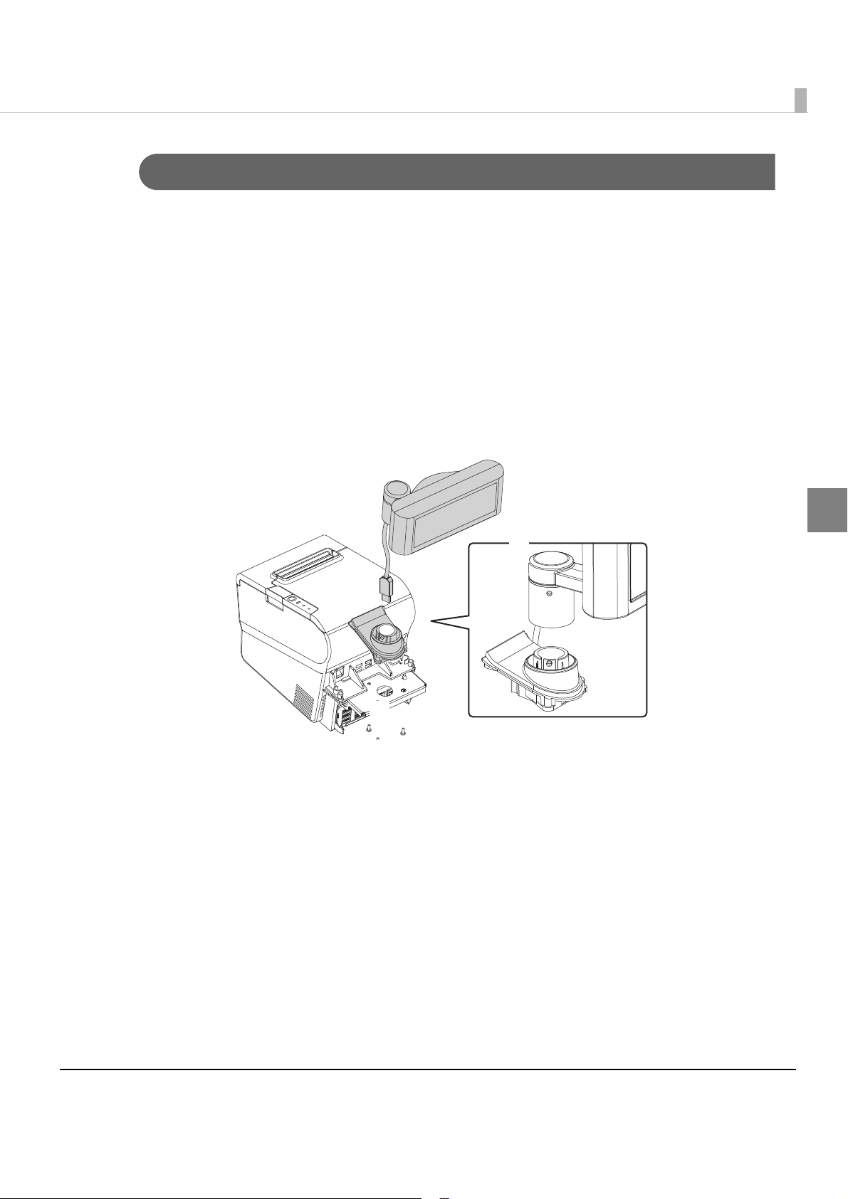
Attaching the Customer Display
If you use the product with the optional customer display, follow the steps below.
Turn over the main body on its front.
1
Align the 3 screw holes on the bundled base with those on the pole
2
mounting plate, and secure the base with the 3 screws included in the
customer display package.
Pass the USB cable through the cable hole on the pole mounting plate.
3
See Illustration ❶.
Align the dowels on the L-shaped pole and the base, and attach the L-
4
shaped pole with the base. See Illustration ❷.
Connect the USB cable with one of the USB connectors.
5
2
49
Page 50
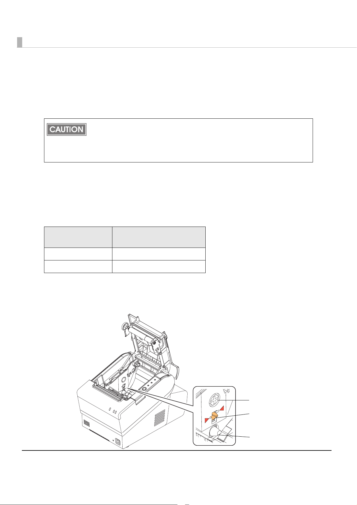
Adjusting the Roll Paper Near-End Sensor
Adjustment screw
Pos itioning
plate
Detection lever
Below are two situations where a roll paper near-end sensor adjustment is required.
•To adjust the detection position to suit the diameter of the roll paper core used.
•To adjust the detection position of remaining amount of paper.
Since roll paper cores vary slightly in shape, depending on roll paper design and
manufacturing tolerances, it is impossible to detect the remaining paper exactly.
Use roll paper with a core whose inner diameter is 12 mm {0.47"} and outer diameter is
18 mm {0.71"} so that the near-end sensor can detect the remaining paper as accurately
as possible.
Follow the steps below to adjust the roll paper near-end sensor.
Open the roll paper cover, and remove the roll paper.
1
Loosen the adjustment screw fastening the sensor, and align the upper
2
edge of the positioning plate with the adjustment position.
Adjustment position
Upper Approx. 27 {1.06"}
Lower (Initial setting) Approx. 23 {0.97"}
Tighten the adjustment screw.
3
After adjustment, make sure that the detection lever operates smoothly.
4
Remaining amount of paper
(outer diameter: mm)
50
Page 51
Connecting the AC Adapter
DC Input connector
Use this product's dedicated AC adaptor.
Be sure to use the included AC adapter as the power supply unit.
Using a nonstandard power supply can result in electric shock and fire.
WARNING
Should a fault ever occur in the included AC adapter, immediately turn off the
power to the printer and unplug the power supply cable from the wall socket.
Be sure to unplug the power supply unit’s cable from the wall socket whenever
connecting or disconnecting the power supply unit to the printer.
Failure to do so may result in damage to the power supply unit or the product.
Make sure the wall socket power supply satisfies the rated voltage requirements
of the power supply unit. Never insert the power supply cable plug into a socket
that does not meet the rated voltage requirements of the power supply unit.
Doing so may result in damage to both the power supply and the product.
Chapter 2 Setup
2
51
Page 52
OS Initial Settings
The following explains the procedures for setting the OS when you turn on the power for this
product for the first time.
When performing setup for the OS, you need a display, a keyboard, and a mouse.
Connect the display when this product is off.
If you connect the display when this product is on, data may not be properly displayed.
Check that the product's power is not on, and connect the display, a
1
keyboard, and a mouse.
Turn on the product.
2
The items shown below, including this resolution information, are
3
displayed as start options when the product is started. Select the item
that corresponds to the display that you are using.
openSUSE 640x480
openSUSE 800x600
openSUSE 1024x768
openSUSE 1280x1024
openSUSE 1600x1200
openSUSE 12.2 (Failsafe)
52
Select a resolution that is not supported by the display can result in a failure to
display anything. If this occurs, restart this product and select an appropriate
resolution.
Page 53

The login screen is displayed. Input the password.
4
The initial settings are as follows.
User name Password
EPSON-USER TMDT
You can change the session at the login screen. The setting at the time of factory
shipment is [KDE Plasma Workspace].
Select [Menu] - [Session Type]. Select [GNOME] or [KDE Plasma Workspace] from
the list.
The OS desktop is displayed. Set the time, date, and the timezone.
5
You can also set the date, time, and the timezone using EPSON TMNet WebConfig.
Chapter 2 Setup
2
53
Page 54
Enabling or Disabling ePOS-Device
Use the desktop shortcut to enable or disable ePOS-Device.
Enable it if you are using ePOS-Device.
If you enabled ePOS-Device, it uses 100 MB or more of memory.
If you are using this product with a PC-POS system or in a virtual environment, we
recommend disabling e-POS-Device.
ePOS-Device is set to [Enabled] in the default settings.
Enabling ePOS-Device
Run [Enabling ePOS-Device] from the shortcut on the desktop.
Disabling ePOS-Device
Run [Disabling ePOS-Device] from the shortcut on the desktop.
54
Page 55
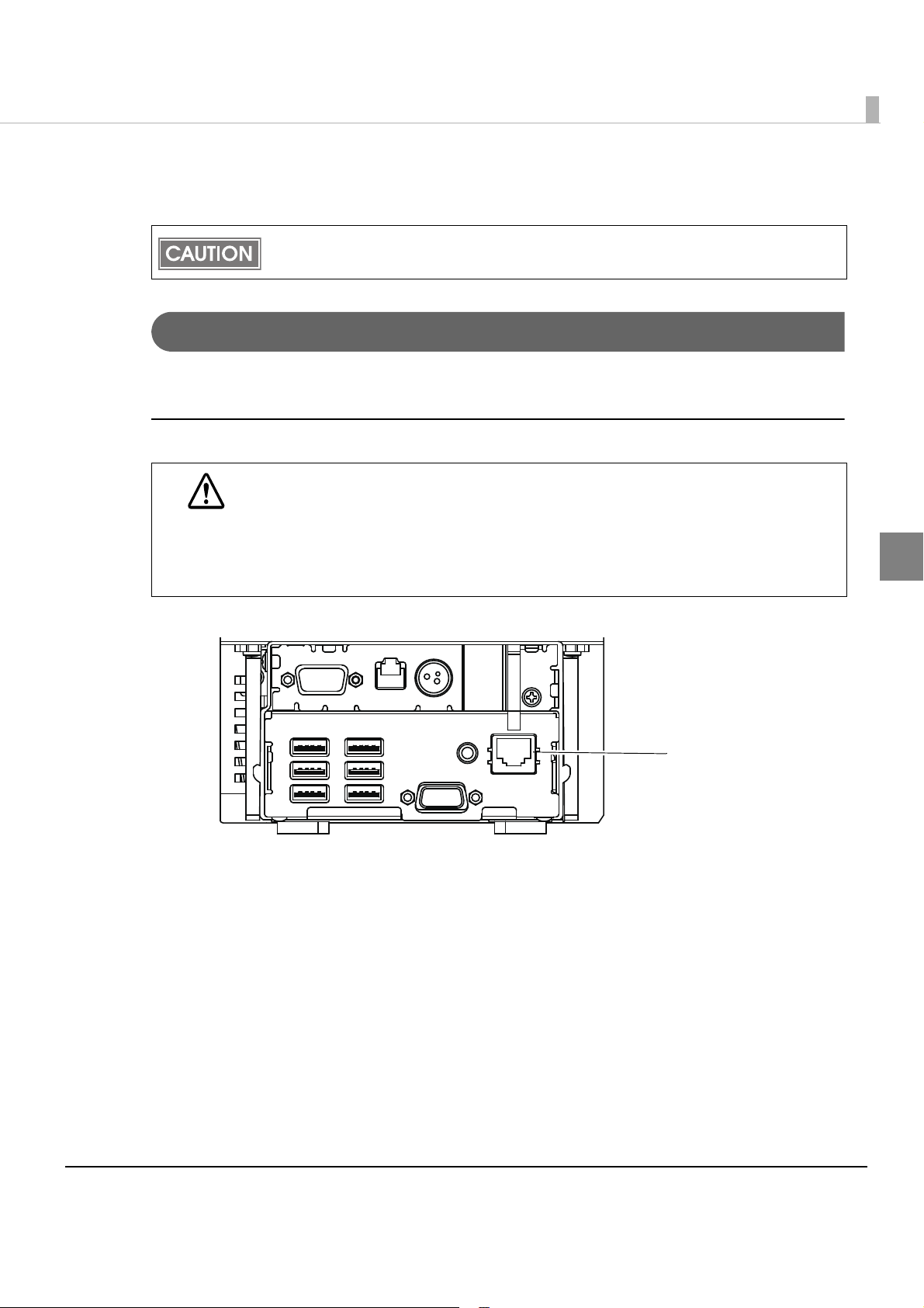
Connecting to the Network
Ethernet connector
The product uses a modular connector specifically designed for the cash drawer. Do not
connect the connector to an ordinary telephone line.
For Ethernet Interface
Connect the product to a network by a LAN cable via a hub.
Connecting the Ethernet interface cable
When LAN cables are installed outdoors, make sure devices without proper surge
protection are cushioned by being connected through devices that do have surge
CAUTION
protection.
Otherwise, the devices can be damaged by lightning.
Never attempt to connect the customer display cable, drawer kick-out cable, or a
standard telephone line cable to the Ethernet connector.
Chapter 2 Setup
2
Insert a category 5e or higher LAN cable into the Ethernet connector until you hear a click.
55
Page 56

Network settings
Perform network settings, such as the IP address. These settings are the same as a Windows PC.
Yo u can perform settings in the following ways.
•Setting in a local environment: Setting with YaST
•Setting on web blowsier from remote/local PC: Setting with EPSON TMNet WebConfig
Setting with YaST
Start YaST.
1
Select [Network Devices] - [Network Settings].
2
The "Network Settings" screen is displayed. Select the device to set from
3
the list of the [Overview] tab, then click [Edit].
56
Page 57

Chapter 2 Setup
The "Network Card Setup" screen is displayed. Change the settings, then
4
click [Next].
2
57
Page 58

EPSON TMNet WebConfig
Yo u can perform settings from a PC for settings via the network. You can also set the IP address
without connecting a display to this product.
Start the Web browser of the PC for settings, and input the following.
1
http://This product's IP address/webconfig/
EPSON TMNet WebConfig starts.
The default IP address for this product is "192.168.192.168".
Select [Wired], then [TCP/IP].
2
The "TCP/IP setting (Wired)" screen is displayed.
Set the IP address and other network settings, then click [Settings].
3
58
Page 59
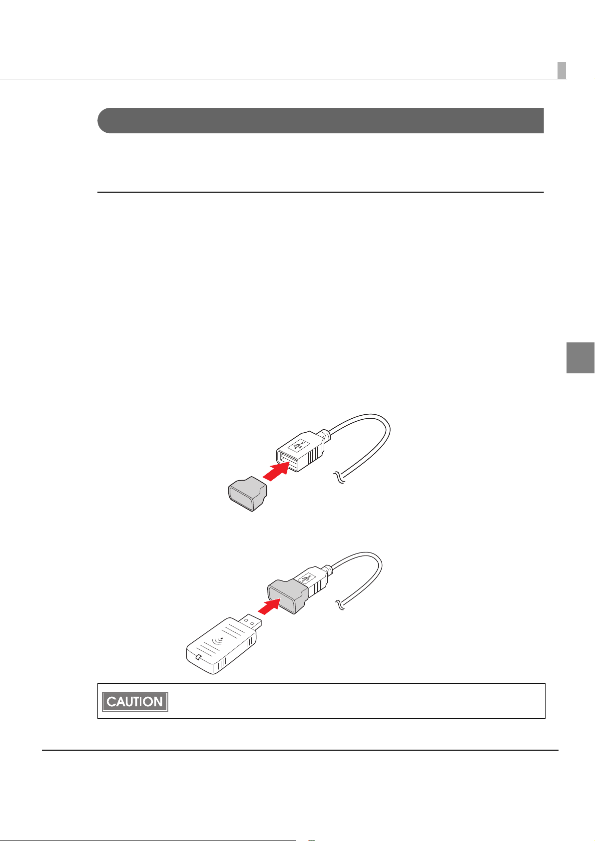
Chapter 2 Setup
For Wireless LAN Interface
The optional wireless LAN cable set (OT-WL01) enables you to use the product with a wireless
LAN connection.
Connecting the wireless LAN cable set
Check whether the following items are included. If any item is damaged, contact your dealer.
•Wireless LAN unit
•USB extension cable
•Affixing tape (1 pair, 2 pieces)
•Rubber cover
• User’s manual
Attach the included rubber cover to the connector of the USB extension
1
cable into which the wireless LAN unit will be inserted, to prevent the unit
from coming off.
Insert the wireless LAN unit into the connector of the cable.
2
2
Adjust the position of the rubber cover so that the description on the label on the back side
of the wireless LAN unit is not covered.
59
Page 60

Connect the USB extension cable to the USB connector of the printer.
Wireless LAN indicator
3
If you want to fix the wireless LAN unit, cut the included affixing tape to fit and put on the
unit, and fix the unit in a place with good communication.
Wireless LAN indicator
The position of the wireless LAN indicator is shown in the illustration below.
Wireless LAN indicator
(Green)
Off
Flashing This wireless LAN unit is connected to the printer and is in operation.
Flashing rapidly
The wireless LAN unit is not connected to the printer. Or the printer
power is OFF.
This wireless LAN unit is connected to the printer and is in operation.
This unit is communicating on a network.
Status
60
Page 61

Chapter 2 Setup
Network settings
Perform network settings, such as the IP address. These settings are the same as a Windows PC.
Yo u can perform settings in the following ways.
•Setting with YaST
•Setting with EPSON TMNet WebConfig
This product cannot use ad hoc mode and infrastructure mode at the same time.
Perform network settings the devices you will connect to this product via ad hoc.
Setting with YaST
Start YaST.
1
(For details on starting YaST, refer to "Starting YaS T" on page 91.)
Select [Network Devices] - [Network Settings].
2
“Network Settings” screen is displayed. Click [Add] in [Overview] tab.
3
2
61
Page 62

“Hardware Dialogue” screen is displayed. Set [Device Type] and
4
[Module Name], then click [Next].
Item Setting
Device Type Select “Wireless” from pulldown menu.
Module Name Input “wlan0“.
“Network Card Setup” screen is displayed. Select [Dynamic Address] or
5
[Statically assigned IP Address].
When select [Dynamic Address] Go to step 7.
When select [Statically assigned IP Address] Go to step 8.
62
Page 63

When Select [Dynamic Address], then set about dynamic address
6
settings. Click [Next]. Go to step 8.
Chapter 2 Setup
When Select [Statically assigned IP Address], then set [IP Address],
7
[Subnet Mask], and [Hostname]. Click [Next]. Go to step 8.
2
63
Page 64
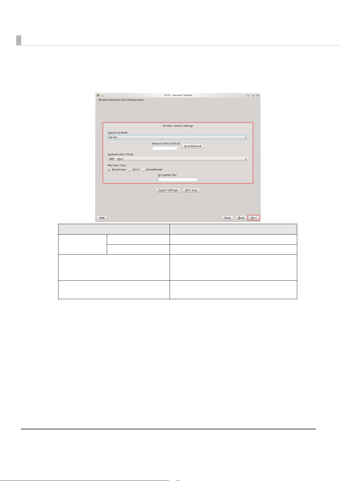
“Wireless Network Card Configuration” screen is displayed.
8
After selecting [Operating Mode], specify the security settings.
Click [Next].
Item Setting
Operating Mode
Ad-Hoc Select if using Ad-Hoc Mode.
Managed Select if using Infrastructure Mode.
Network Name (ESSID)
Authentication Mode
Input the network ESSID.
If the network has already been configured, click
[Scan Network] to display the ESSID.
For specifying the security setting.
Set in accordance with the network environment.
64
Page 65

“Network Settings” screen is displayed.
POWER='no'
POWER='none'
9
The device added to the list in the [Overview] tab is displayed.
Click [OK].
Chapter 2 Setup
The following file is created if settings of a wireless LAN module are
10
specified.
/etc/sysconfig/network/ifcfg-wlan0
Edit the ifcfg-wlan0 file. Open the file and edit as shown below.
11
2
65
Page 66
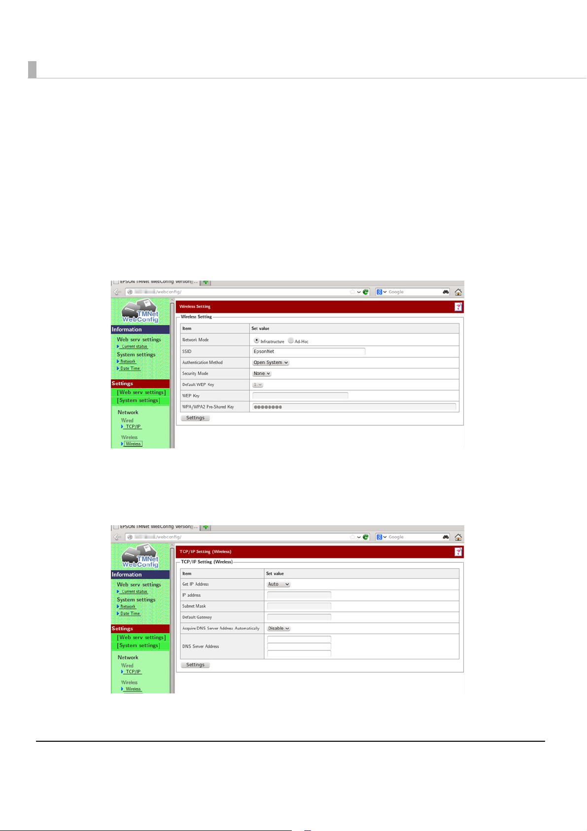
Setting with EPSON TMNet WebConfig
Yo u can perform settings from a PC for settings via the network. You can also set the IP address
without connecting a display to this product.
Start a Web browser of the PC for the settings, and input the following.
1
http://This product's IP address/webconfig/
EPSON TMNet WebConfig starts.
The default IP address for this product is "192.168.192.168".
Select [Wireless], then [Wireless].
2
The "Wireless Settings" screen is displayed.
Perform network settings for a wireless LAN, then click [Settings].
3
Select [Wireless], then [TCP/IP].
4
The "TCP/IP Settings (Wireless)" screen is displayed.
Set the IP address and other network settings, then click [Settings].
5
66
Page 67
Installing Drivers and Applications
Installing and Setting the Drivers
Yo u must install drivers depending on the type of external devices.
When you want to control an external TM printer with a printer driver, install CUPS driver.
For more about how to install and set the drivers, refer to the manual for each driver.
Printer settings can not be specified at [Printer] of YaST but at CUPS. The CUPS access
procedure is as follows. Input the following in the browser address bar.
http://localhost:631
CUPS diriver is installed in this product. The location of the installer is as follows.
/opt/epson/tmt-cups/tmt-cups-1.4.2.0.tar.gz
The location of the CUPS manual is as follows.
/opt/epson/tmt-cups/manual/...
The installers for JavaPOS ADK is included. Install them as necessary. The location of
the installer is as follows.
opt/epson/UPOSforDT/Epson_JavaPOS_ADK_11310.tar.gz
Chapter 2 Setup
2
It is not necessary to install printer drivers for the models shown below. By specifying
settings using CUPS, you can select the PPD file corresponding to the model. It is
necessary to install printer drivers if adding any printers other than those listed below.
TM-T88V
TM-T70II
TM-T20
TM-T82
TM-T82II
Installing Applications
Install the applications you want to use.
67
Page 68

Service Startup Settings
It is necessary to perform service setup settings for the TM-T88V-DT depending on the system
operation method.
Use EPSON TMNet WebCo nfig to perform the service setup settings, following the procedures
below.
Start a Web browser of the PC for the settings, and input the following.
1
http://This product's IP address/webconfig/
EPSON TMNet WebConfig starts.
Select [Web serv settings], then [Startup settings].
2
The "Startup settings" screen is displayed.
Set the following, then click [OK].
3
Item Description
Device control Set whether to control POS peripherals using this product or not.
Automatic update of
Web content
Support system and startup settings for each service are as follows.
System Device control
ePOS-Device API Enabled (default) Disable / Enable
ePOS-Device XML Enabled (default) Disable
Set whether to use the automatic update for Web content or not.
Automatic update of Web
content
68
Page 69

Registering Web Contents
ePOS-Device_UM_E_Sample.zip ................ : Zip file
|
├ index.html
├ css
|└ *.css
├ img
|├ *.bmp
|├ *.jpg
|└ *.png
├ js
|└ *.js
└ sample
└ *.html
<Example for sample program>
Perform registration as follows, depending on the system and method in use.
If placing Web content in this product's Web server using ePOS-Device API, register the Web
content.
When you upload Web content, the existing registered Web content is discarded.
(The folders under U_data remain.)
Specifications of the file to be registered
•You can register the following for Web content.
HTML files, CSS files, JavaScript, image data, Perl scripts, php scripts
•You can use SQLite3 as a database.
•If including scripts in Web content, follow the naming rules below.
For Perl scripts: *.cgi
Chapter 2 Setup
For php scripts: *.php
•Zip the files to be registered all together. The zip file name is arbitrary.
Use one-byte alphanumeric characters (ASCII characters) for a zip file name and
sub-folder name.
The maximum size of the files before zipping is 100 MB. Otherwise, registering fails.
Cautions for the files to be registered
•Web contents cannot be registered additionally. All files are overwritten and registered. Zip
web contents before registering.
2
69
Page 70

•When you access to registered web contents from an input terminal and so on, the URL differs
epsonsample.zip
|
└ webpage............................ : A folder added
├ index.html
├ css
|└ *.css
├ img
|├ *.bmp
|├ *.jpg
|└ *.png
├ js
|└ *.js
└ sample
└ *.html
epsonsample.zip
|
├ index.html
├ css
|└ *.css
├ img
|├ *.bmp
|├ *.jpg
|└ *.png
├ js
|└ *.js
└ sample
└ *.html
➀
➁
depending on the folder structure of the zip file.
➀ http://[the product’s IP address]/index.html
➁ http://[the product’s IP address]/webpage/index.html
70
Page 71

Chapter 2 Setup
Registering Web content
Use EPSON TMNet WebCo nfig to register Web contents on this product, following the
procedures below.
Start a Web browser of the PC for the settings, and input the following.
1
http://This product's IP address/webconfig/
EPSON TMNet WebConfig starts.
Select [Web serv settings], then [Update settings].
2
The "Web content update settings" screen is displayed.
Select [Browse...], and specify the file (zip file format) you want to
3
register, then click [Upload].
2
71
Page 72

Registering device control script files
Use EPSON TMNet WebCo nfig to register device control scripts on this product, following the
procedures below.
This registration is used when registering device control script files, such as serial
communication devices, using ePOS-Device.
72
Start a Web browser of the PC for the settings, and input the following.
1
http://This product's IP address/webconfig/
EPSON TMNet WebConfig starts.
Select [Web serv settings], then [Register/delete].
2
The "Control script" screen is displayed.
Select [Browse...], and specify the control script you want to register,
3
then click [Registration].
Page 73

Connecting External Devices
Connect external devices as necessary.
Connecting a Mouse and Keyboard
Connect a USB mouse and USB keyboard to the USB connectors.
When connecting the USB keyboard, keymap specified on the OS might not match the
keymap of the connected keyboard. If this occurs, specify the keymap settings.
Connecting a Display
Connect a display to the VGA connector.
Connect the display when this product is off.
If you connect the display when this product is on, data may not be properly displayed.
Chapter 2 Setup
2
Connecting a Printer
Connect a printer that is supported by the system and applications. You can connect it using the
following methods.
•USB connection
•Serial connection
•Network connection
(For network printers, we recommend setting the IP address in advance.)
The connection method varies depending on your system in operation. For details, refer to
"Development Information for Each System" on page 129.
73
Page 74

Connection POS Peripherals
•Connect POS peripherals with USB interface to the USB connectors.
•Connect POS peripherals with serial interface to the COM connector or use USB-serial conver-
sion cables to convert them and connect them to the USB connectors, and install the drivers for
each model. For details such as the order in which to conn
manual.
•You can perform the connection test from EPSON TMNet WebConfig. For details, refer to"Set-
ting the Devices" on page 77.
Dedicated drivers are necessary, depending on the devices.
Acquire and install the drivers as necessary.
ect them, refer to each device's user's
74
Page 75
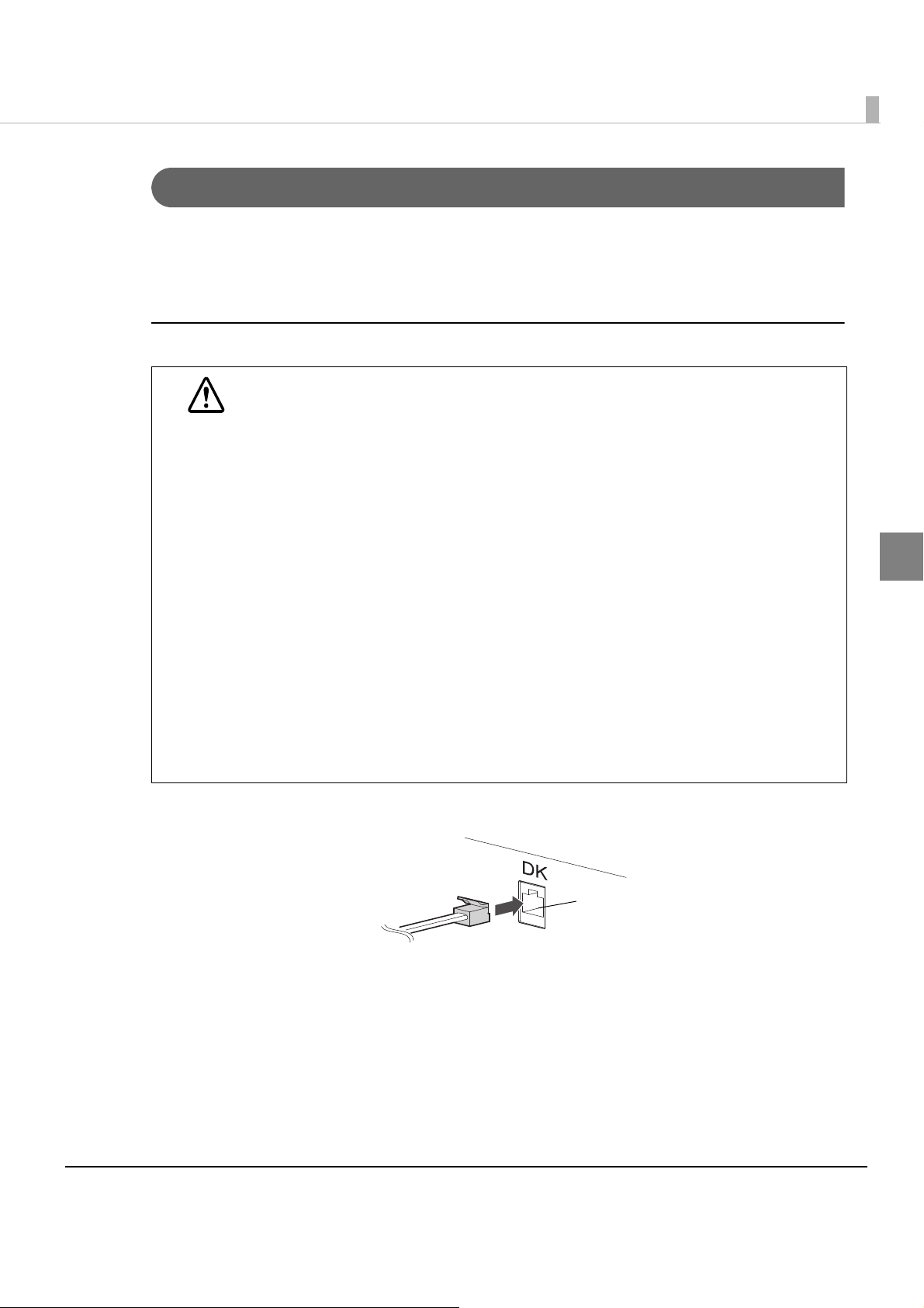
Connecting the Cash Drawer
Drawer kick-out connector
When using a cash drawer, connect the cash drawer.
Use the cash drawer handled by EPSON or your dealer.
If the optional external buzzer is used, you cannot use a cash drawer.
Connecting the Drawer Kick-out Cable
Specifications of drawers differ a great deal, depending on makers or models.
When you use a drawer other than the specified, make sure its specifications meet
WARNING
the following conditions.
Otherwise, devices may be damaged.
The load, such as a drawer kick-out solenoid, must be connected between pins 4 and
2 or pins 4 and 5 of the drawer kick-out connector.
When the drawer open/close signal is used, a switch must be provided between
drawer kick-out connector pins 3 and 6.
The resistance of the load, such as a drawer kick-out solenoid, must be 24
or the input current must be 1A or less.
Be sure to use the 24V power output on drawer-kick out connector pin 4 for driving the
equipment.
Use a shield cable for the drawer connector cable.
Two driver transistors cannot be energized simultaneously.
Leave intervals longer than 4 times the drawer driving pulse when sending it
continuously.
Be sure to use the printer power supply (connector pin 4) for the drawer power
source.
Do not insert a telephone line into the drawer kick-out connector.
Doing so may damage the telephone line or printer.
Chapter 2 Setup
or more
2
Connect the connector of the drawer kick-out cable to the printer.
75
Page 76

Drawer Connection Circuitry
F. G
+24V
Shielded drawer kick-out connector
Printer side
User side [Drawer kick-out side]
Drawer open/close switch
Drawer kick-out solenoid
Control device
1
2
3
4
5
6
76
Page 77

Setting the Devices
Registering a Printer
Use EPSON TMNet WebCo nfig to register a network printer on this product, following the
procedures below. This product's printer is already registered, so settings are not necessary.
Chapter 2 Setup
Start a Web browser of the PC for the settings, and input the following.
1
http://This product's IP address/webconfig/
EPSON TMNet WebConfig starts.
Select [Web serv settings], then [Printer].
2
The "Printer" screen is displayed.
2
77
Page 78

Set the following, then click [Registration].
3
The information for the registered device is displayed in [Registered printer].
Item Description
Device ID
Type Select network printer.
Model no. Select the printer model.
IP address Input the IP address of the printer you want to control.
Retry interval Set the printer's retry interval.
Click [Test printing] and check if the registered printer operates properly.
4
Set the device ID for the printer you want to register. (Any character
string)
78
Page 79

Chapter 2 Setup
Customer Display Settings
Use EPSON TMNet WebCo nfig to register the dedicated customer display DM-D110, following
the procedures below.
Start a Web browser of the PC for the settings, and input the following.
1
http://This product's IP address/webconfig/
EPSON TMNet WebConfig starts.
Select [Web serv settings], then [Display].
2
The "Customor display settings" screen is displayed.
Select [Use] and perform the following settings.
3
Item Description
Used for customer display communication settings.
Communications
settings
Brightness settings
If you changed the DM-D110 (dedicated model) dip switch settings,
change the communication settings in accordance with those
changes. (If you do not change the dip switch settings, use the default
settings.)
Set the brightness of the customer display in percentages.
You can set 20%, 40%, 60%, or 100%. The maximum brightness is 100%.
2
Device ID for the dedicated customer display is fixed to "local_display".
Check the settings and click [OK].
4
79
Page 80

Registering a Key Input Device
Use EPSON TMNet WebCo nfig to register a key input device on this product, following the
procedures below.
Start a Web browser of the PC for the settings, and input the following.
1
http://This product's IP address/webconfig/
EPSON TMNet WebConfig starts.
Select [Web serv settings], then [Key input device].
2
The "Key input device" screen is displayed.
Set the following, then click [Registration].
3
The information for the registered device is displayed in [Registered key input
device].
Item Description
Device ID Set the device ID for the key input device you want to control.
Select the key input device model.
Device name
Control script Select the script to control the device.
Unregistered key input devices that are currently connected to the unit are
listed.
80
Page 81
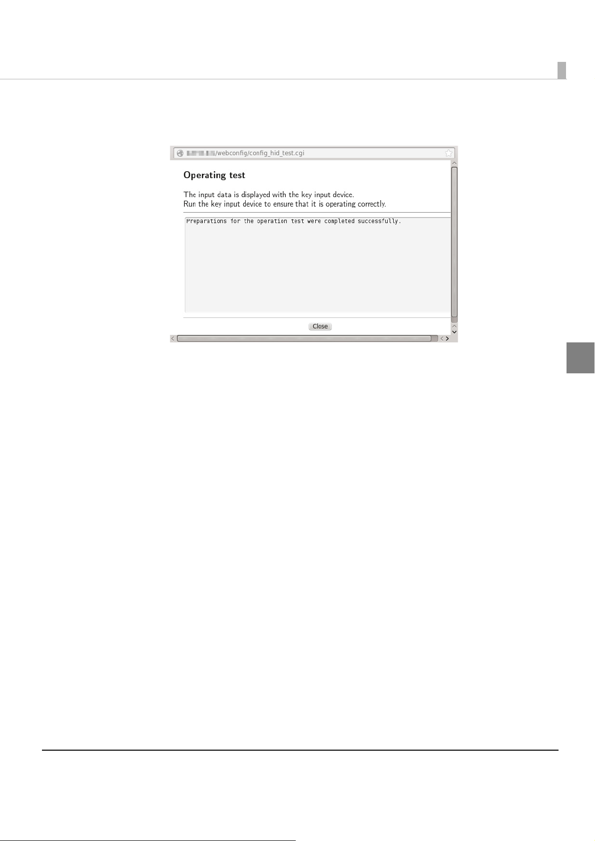
Click the [Operating test].
4
The [Operating test -- Webpage Dialog] screen is displayed.
Chapter 2 Setup
Use the key input device, and check if the registered key input device
5
operates properly.
2
81
Page 82

Serial Communication Device Registration
Use EPSON TMNet WebCo nfig to register a serial communication device with this product,
following the procedures below.
Start a Web browser of the PC for the settings, and input the following.
1
http://This product's IP address/webconfig/
EPSON TMNet WebConfig starts.
Select [Web serv settings], then [Serial communications].
2
The "Serial communications devices" screen is displayed.
82
Page 83

Set the device ID. (Any character string)
3
Select the product name or port for the serial communication device.
4
Item Description
Physical serial port This is the serial port on the back of this product.
These are the USB ports on the back of this product.
If connecting a serial device using a COM-USB cable, select the
corresponding USB port. You can check the USB port number using
[Display port locations].
USB port 1 to 6
Chapter 2 Setup
Set the following, then click [Registration].
5
Information of the registered device is displayed in the [Registered serial
communications device].
Item Description
Control script Select the control script to control the serial communication device.
Communications
speed (bps)
Data bit Select the data bit.
Parity Select the parity.
Stop bit Select the stop bit.
Flow control Select whether there is flow control or not.
Select the communication speed.
2
83
Page 84
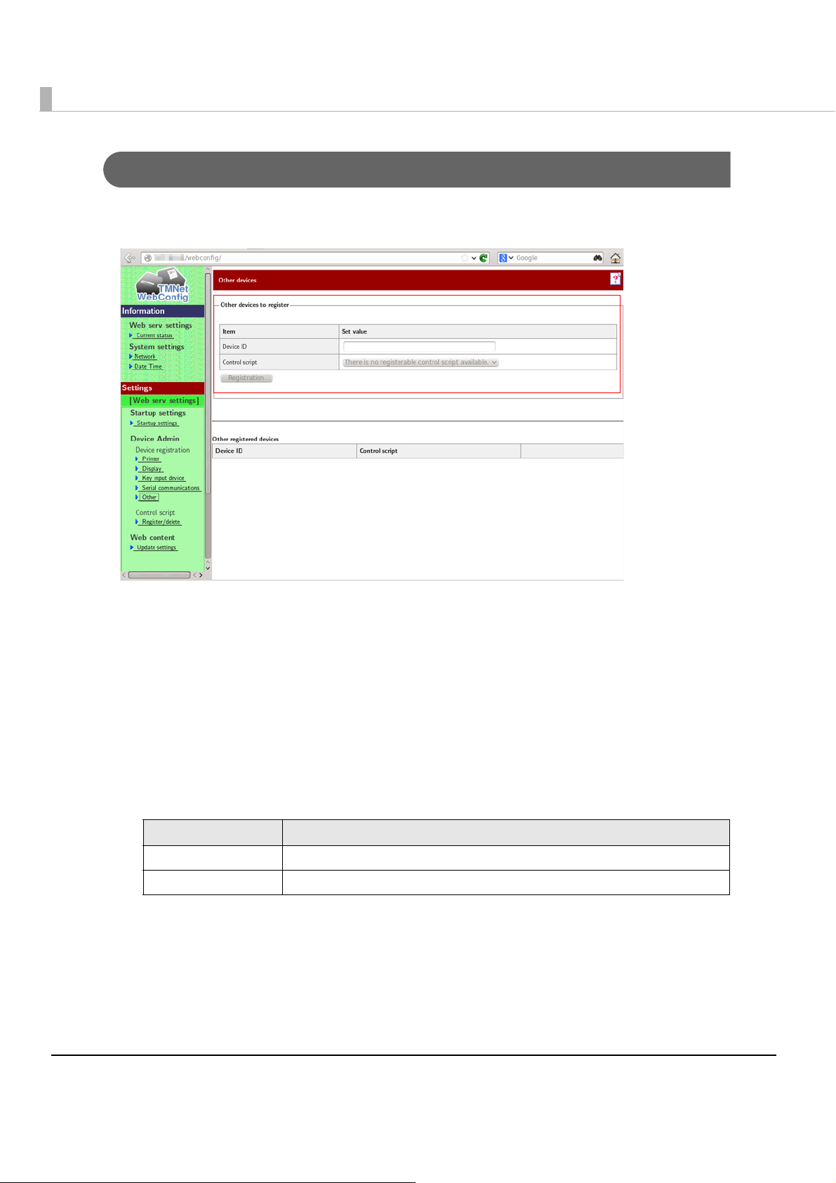
Registering Other Devices
Use EPSON TMNet WebCo nfig to register other devices on this product, following the
procedures below.
Start a Web browser of the PC for the settings, and input the following.
1
http://This product's IP address/webconfig/
EPSON TMNet WebConfig starts.
Select [Web serv settings], then [Other].
2
The "Other devices" screen is displayed.
Set the following, then click [Registration].
3
The information for the registered device is displayed in [Other registered devices].
Item Description
Device ID Set the device ID for the device you want to control.
Control script Select the control script to control the other devices.
84
Page 85
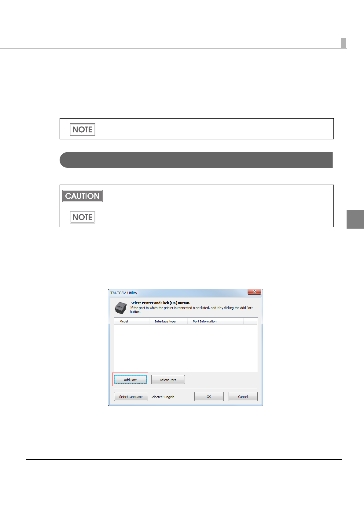
Chapter 2 Setup
Printer Settings
Yo u can register logos in the NV (non volatile) memory area in the printer unit and print them.
Registering of logos is performed from the TM-88V Utility on the Windows computer via the
network.
You can also directly print raster format image data as logos without registering them on the
product.
Register Procedures
Follow the steps below to register logos.
Check that this printer and the computer used for specifying settings are connected to the
network.
It is recommended to write all logos together in the printer when you register more than one
logo.
2
On the computer used for specifying settings, select [Start]-[All
1
Programs]-[TM-88V Utility].
The TM-T88V Utility is started.
Click [AddPort].
2
85
Page 86

Select [Ethernet].
3
Click [Search] and select the IP address of this printer from the displayed
4
IP addresses. Click [OK].
86
Display returns to the port selection screen.
If the IP address of this printer is not displayed when [Search] is clicked, input the
IP address of this printer in the [IP Address:] input field, then click [OK].
Click [Communication Test] to perform a communication test for this printer.
Epson recommends performing a communication test before adding this printer.
Page 87

Select this printer. Click [OK].
5
Select [Storing Logos], and then click [Add].
6
Chapter 2 Setup
2
87
Page 88

Specify the image data file for logo.
7
The file must be smaller than W: 2047 H: 831 pixels (dots) in bmp, jpeg, gif, or png
format.
If the logo width exceeds the paper width (80 mm printing: 512 dots, 58 mm printing:
360 dots), an error message appears. Click [OK], and go to Step 4 to reduce the
size in the [Logo Edit] screen.
On the [Logo Edit] screen, click [Monochrome] or [Multi-tone] to select
8
the image format to output.
[Monochrome] reduces the colors to black and white. [Multi-tone] reduces the colors to 16
colors (graduation) in grayscale.
88
When the Mode for Storing Logo is set to “Key-code Nonuse Mode (not recommended),”
[Multi-tone] does not appear.
Page 89
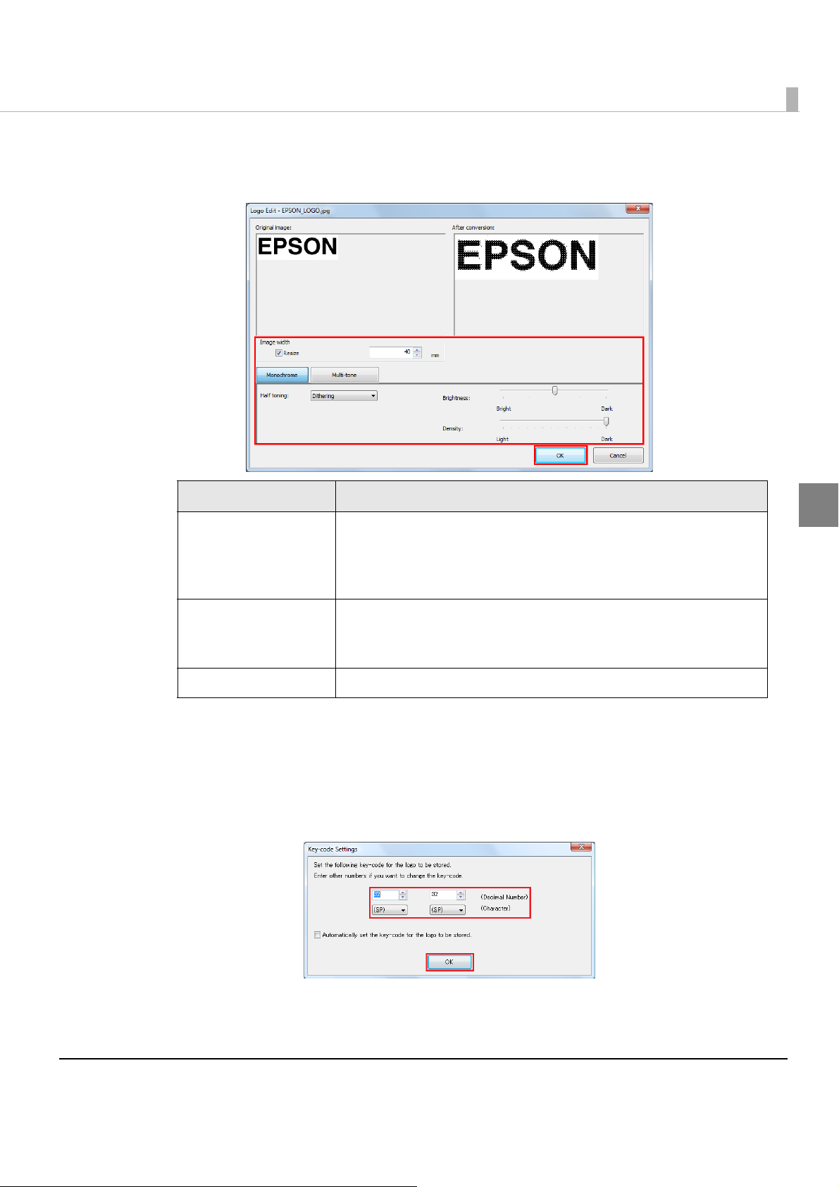
Chapter 2 Setup
Edit the image data checking the preview window on the right, and
9
then click [OK].
Item Description
Set whether you will resize the image or not and the image size after
Resize
resizing. (Units: mm)
If the image size is wider than the paper width and it is not resized,
the part out of the paper width will not be printed.
2
Select from Dithering, Error diffusion, or None.
Half toning
Brightness Set the brightness.
When Mode for Storing Logo is set to “First Key-code Selection Mode” and the checkbox
for [Automatically set the key-code for the logo to be stored] is not checked, the [Key-code
Settings] screen appears (Step 6).
Set a key code, and then click [OK].
10
Logo data is added to the list.
If Monochrome is selected in Step 4, Halftoning cannot be
changed.
89
Page 90

When you register more than one logo, repeat the Steps 1 to 6.
11
After registering all logo data, check the indicator on the right to make
12
sure that the data size is small enough to write in the printer, and then
click [Store to Printer].
The logo data is stored in the printer.
90
Page 91

Chapter 2 Setup
Product settings
Changing the Session
Yo u can change the session at the login screen. The setting at the time of factory shipment is
[KDE Plasma Workspace].
At the login screen, select [Menu] - [Session Typ e ]. Select [GNOME] or [KDE Plasma Workspace]
from the list. Log in to display the selected session screen.
The selected session is stored in memory and applied from your
next login and thereafter.
Starting YaST
How to start YaST from the GUI of KDE:
Click the icon at the lower-left of the screen, then select [Computer] - [YaST].
The password is the root user password of "TMDT".
How to start YaST from the command line:
Yo u can start YaST b y using the following commands.
>su
Password:(root user’s password "TMDT“)
2
#/sbin/yast2
91
Page 92

Resolution settings
The items shown below, including this resolution information, are displayed as start options
when the product is started. Select the item that corresponds to the display that you are using.
•openSUSE 640x480
•openSUSE 800x600
•openSUSE 1024x768
•openSUSE 1280x1024
•openSUSE 1600x1200
•openSUSE 12.2 (Failsafe)
openSUSE 12.2 (Failsafe) is the mode used when a system fault occurs. The system is
started with the selected optimal resolution.
Default resolution setting
Start YaST.
1
(For details on starting YaST, refer to "Starting YaS T " on page 91.)
Select [System] - [Boot Loader].
2
“Boot Loader“ screen is displayed. Select the resolution you want to set
3
as the default, then click [Set as Default]. After selecting, click [OK].
Using [Set as Default] sets the specified resolution as the default resolution.
The computer might not start if the kernel start option for edit is changed. Only
change this option if you fully understand the affects of making such a change.
Starting is not affected by changing the order of the options or by the [Set as
Default] operation.
92
Page 93

Changing DisplayLanguage
Yo u can change the display language according to the procedures described below.
Always be sure to change the display language on YaST.
Start YaST.
1
(For details on starting YaST, refer to "Starting YaS T" on page 91.)
Select [System] - [Language].
2
“Language” screen is displayed. Set "Primary Language” and
3
“Secondary Language”, then click [OK].
Log out once and then log in again.
4
The language will not be changed unless you log in again.
Chapter 2 Setup
2
Power button settings
KDE
Click the icon at the lower-left of the screen, select [Applications] -
1
[System Settings].
“System Settings” screen is displayed. Click [Power Management].
2
“Power Management” screen is displayed.
3
Set for [Button events handling].
93
Page 94

GNOME
Start the dconf editor.
1
Select [org] - [gnome] - [settings-daemon] -[plugins] - [power].
2
Settings are displayed on the right-side of the screen. Set for [Power
3
button action].
Time settings
Start YaST.
1
(For details on starting YaST, refer to "Starting YaS T " on page 91.)
Select [System] - [Date and Time].
2
“Date and Time” screen is displayed. Set [Region], [Time Zone], and
3
[Date and Time], then click [OK].
Auto-mount settings
Start the dconf editor.
1
Select [org] - [gnome] - [desktop] - [media-handling].
2
Settings are displayed on the right-side of the screen. Set for auto-mount.
3
94
Page 95

Chapter 2 Setup
locking wire saddle
U-shaped part
Attaching the Connector Cover
To protect the cables, attach the connector cover in the steps below. When the optional customer
display unit is not installed, attach the connector cover with the U-shaped part.
Be sure to hold both sides of the connector cover when attaching it, or the it may
become damaged.
WARNING
When pulling out the cables whose connectors do not lock themselves (USB cables and
Line-Out cable) from the cable exits on the back, fix the cables with the lock wire saddle to
prevent the cables from coming off.
Pass the interface cables through the locking wire saddle on the pole
1
mounting plate.
Pass each cable through the cable exits at the bottom of the connector
2
cover.
If you use the product with the optional customer display, remove the U-
3
shaped part from the connector cover. If you use the product without
the optional customer display, keep the U-shaped part attached.
2
95
Page 96

Align the tabs on the upper side of the connector cover with the
4
notches on the main body, and push the front part of it to click onto the
printer cover.
Hold the lower part of the connector cover, align the tabs on the upper
5
side of it with the notches on the main body, and push the front part of
connector cover to attach it.
Turn over the main body back on its bottom, and make sure the cables
6
are not pinched.
96
Page 97
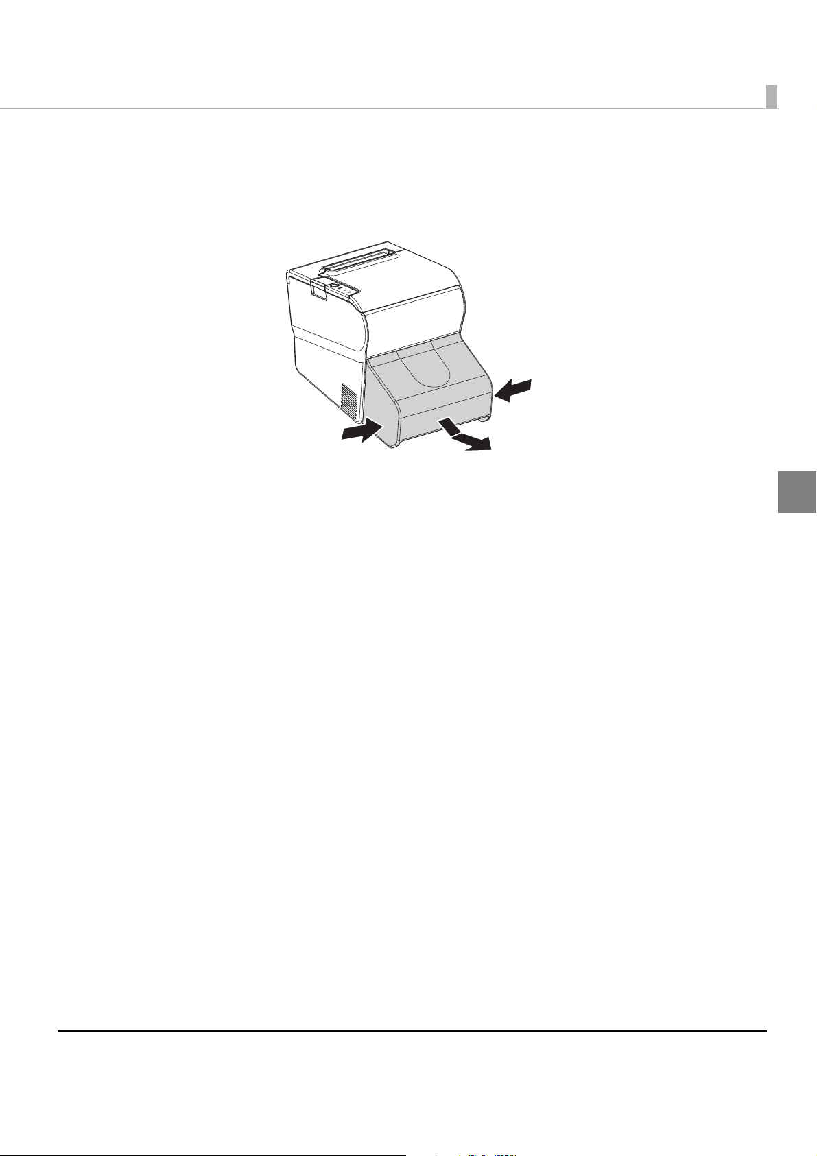
Chapter 2 Setup
Removing the Connector Cover
To remove the connector cover, push the connector cover down while pushing both sides of the
connector cover inward to detach the hooks form the printer case.
2
97
Page 98

Attaching the Power Button Cover
Align the inside edge of the power button cover with the upper edge of the
power button.
Printer reset button
Power button
Align the left edge of the power
button cover with the righr edge of
the printer reset button.
Attach the power button cover that comes with the product onto the power button to prevent
accidental operation of the power button.
Follow the steps below to attach the power button cover.
It is recommended to clean the area around the power button with a cloth moistened with
alcohol before you attach the cover.
Open the power button cover.
1
Peel off the backing paper.
2
Attach the power button cover as shown in the illustration below.
3
98
Page 99

Chapter 3 Preinstalled OS Information
Preinstalled OS Information
openSUSE
Preinstallation information
Item Details
SSD format
File system ext3
Volume label TM-DT
Preinstalled software*
OS Linux
Driver N2600+NM10
based on openSUSE
Embedded VGA driver
Sound driver
Network controller driver
OT-WL01 driver (Wireless LAN driver)
Virtual COM port driver
LED controll driver
Tool TMT-CUPS dirver (Driver for EPSON TM printer)
JavaPOS (The installer is bundled)
ePOS-Device Version 2.00
Mozilla Firefox Version 19.02
Network information (Default)
IP address 192.168.192.168
Subnet mask 255.255.255.0
User information (Default)
User Name EPSON-USER
User Password TMDT
EPSON TMNet WebConfig Information (Default)
User Name epson
User Password epson
3
*: This product is based on openSUSE 12.2. The following software is excluded from standard
installation. You can add software by mounting the openSUSE 12.2 DVD.
•Multimedia
99
Page 100
•Office Software
•Graphics
•Games
•Disc Proprietary branding-openSUSE package
Recovery
Follow the steps below to perform the recovery.
When the recovery procedure is performed, all data will be deleted. Back up any neces-
sary data before performing the procedure.
Recovery requires about 10 minutes.
Turn off the power of the product.
1
Connect a DVD drive, and a USB keyboard to the product's USB
2
connectors.
Connect a display to the product's VGA connector.
3
Turn on the power of the product, and insert the recovery disk into the
4
DVD drive.
Restart the product.
5
The system starts using the recovery disk. When a message that says
6
“Do you really want to recover internal storage?” is displayed, select
[yes].
You can not cancel recovery by the [*] key.
A confirmation message that says “All data on the storage will be
7
deleted?” is displayed. Click [Yes].
Recovery is performed.
100
 Loading...