


English
User’s Manual. . . . . . . . . . . . . . . . . . . . 1
Manuel de l’utilisateur . . . . . . . . . . . . . . . 9
Manual do utilizador . . . . . . . . . . . . . . . 17
Manual del usuario. . . . . . . . . . . . . . . . 25
411943401
7
C
USB
RS-232
IEEE1284
10BASE-T/
100BASE-TX
DK
DC24V
2
1
6
3
5
4
A
B
D
English
㩷
ii
English
E
F
G
iii
H
J
K
I
L
M
English
iv
English
P
Q
N8O
9
a
R
S
DSW2
DSW1
v
English
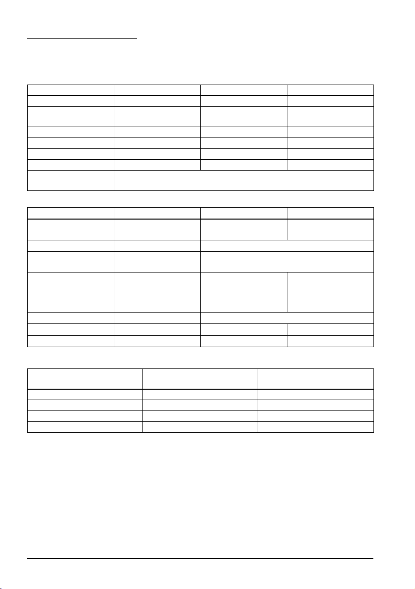
DIP Switch Tables
When using Serial Interface
DIP Switch Bank 1
SW Function ON OFF
1-1 Data receive error Ignored Prints “?”
1-2 Receive buffer
1-3 Handshaking XON/XOFF DTR/DSR
1-4 Data word length 7 bits 8 bits
1-5 Parity check Enabled Disabled
1-6 Parity selection Even Odd
1-7
1-8
capacity
Transmission speed (See table A.)
DIP Switch Bank 2
SW Function ON OFF
2-1 Handshaking
2-2 Do not change settings Fixed to OFF
2-3
2-4
2-5 Release condition of
2-6 Do not change setting. Fixed to OFF
2-7 I/F pin 6 reset Enabled Disabled
2-8 I/F pin 25 reset Enabled Disabled
(BUSY condition)
Print density See Table B
receive buffer BUSY (If
receive buffer capacity
set to 4KB.)
45 bytes 4KB
Receive buffer full Offline or
Releases BUSY when
remaining receive buffer
capacity reaches
138 bytes.
Receive buffer full
Releases BUSY when
remaining receive buffer
capacity reaches
256 bytes.
Table A
Transmission speed (bps) bits
per second
*1
38400
4800 OFF ON
9600 ON OFF
19200 OFF OFF
*1: When DIP switches 1-7 and 1-8 are on, the transmission speed can be selected from one of seven
speeds: 2400, 4800, 9600, 19200, 38400, 57600, and 115200 bps by control commands.
SW1-7 SW1-8
ON ON
vi
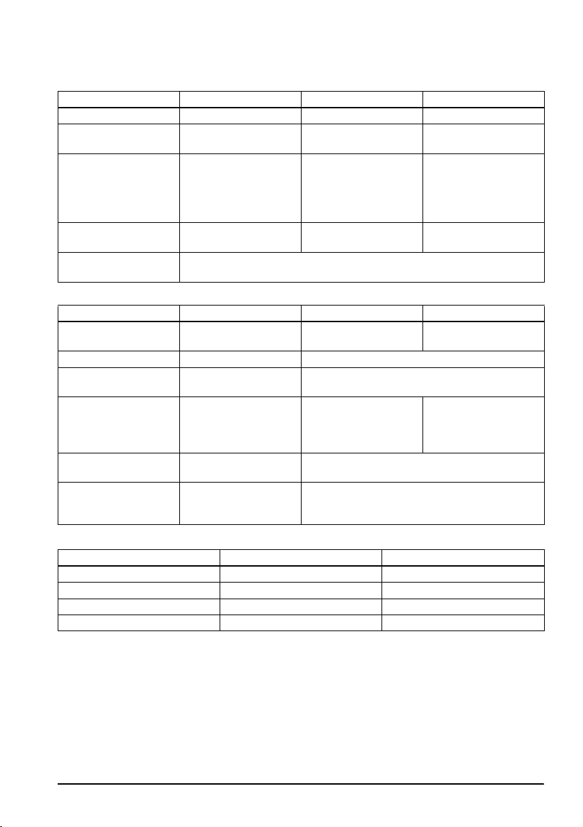
When using Parallel Interface
DIP Switch Bank 1
SW Function ON OFF
1-1 Auto line feed Always enabled Always disabled
1-2 Receive buffer
1-3 Select paper sensors to
1-4 Error signal output from
1-5~
1-8
capacity
output paper-end
signals (default value
of a command) from
parallel I/F.
parallel I/F
DIP Switch Bank 2
SW Function ON OFF
2-1 Handshaking
2-2 Do not change settings Fixed to OFF
2-3
2-4
2-5 Release condition of
2-6
2-7
2-8 I/F pin 31 reset signal
(BUSY condition)
Print density See Table B
receive buffer BUSY (If
receive buffer capacity
set to 4KB.)
Do not change setting. Fixed to OFF
(Do not change
setting)
45 bytes 4KB
Disabled Roll paper end sensor
Disabled Enabled
Undefined
Receive buffer full Offline or
Releases BUSY when
remaining receive buffer
capacity reaches
138 bytes.
enabled, Roll paper
near-end sensor
enabled
Receive buffer full
Releases BUSY when
remaining receive buffer
capacity reaches
256 bytes.
Fixed to ON
English
Table B
Print density/low power SW2-3 SW2-4
Print density “Normal” OFF OFF
Print density “Medium” ON OFF
Print density “Dark” OFF ON
Do not set ON ON
vii
English
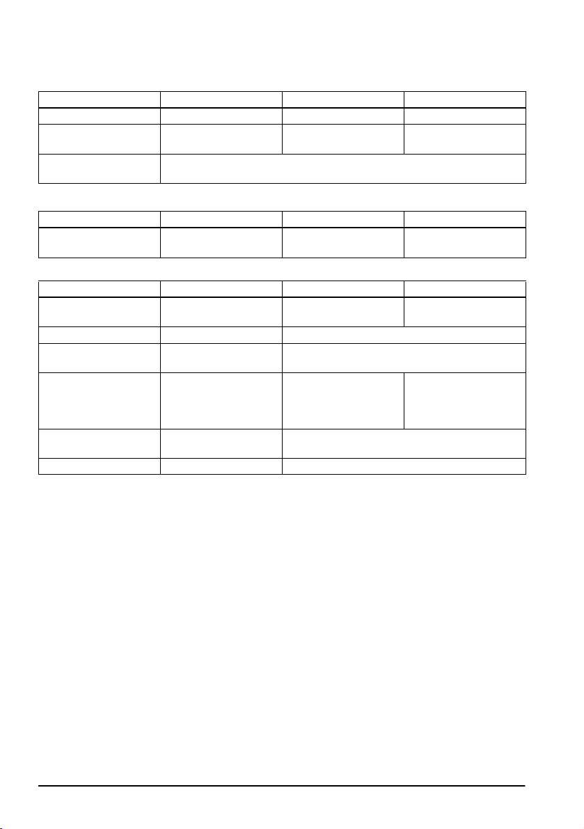
When using USB/Ethernet/Wireless LAN Interface
DIP Switch Bank 1
SW Function ON OFF
1-1 Auto line feed Always enabled Always disabled
1-2 Receive buffer
1-3~
*1
1-8
*1: When using the USB interface on a model with a serial or parallel interface, the function of DIP switch
1-8 is as follows.
SW Function ON OFF
1-8 Power saving function
capacity
for USB
DIP Switch Bank 2
SW Function ON OFF
2-1 Handshaking
2-2 Do not change settings Fixed to OFF
2-3
2-4
2-5 Release condition of
2-6
2-7
2-8 Do not change setting.
*2: Whether DIP switch 2-8 is set to ON or OFF is dependent on the printer model.
(BUSY condition)
Print density See Table B
receive buffer BUSY (If
receive buffer capacity
set to 4KB.)
Do not change setting. Fixed to OFF
45 bytes 4KB
Undefined
Disabled Enabled
Receive buffer full Offline or
Releases BUSY when
remaining receive buffer
capacity reaches
138 bytes.
Receive buffer full
Releases BUSY when
remaining receive buffer
capacity reaches
256 bytes.
*
2
viii
English
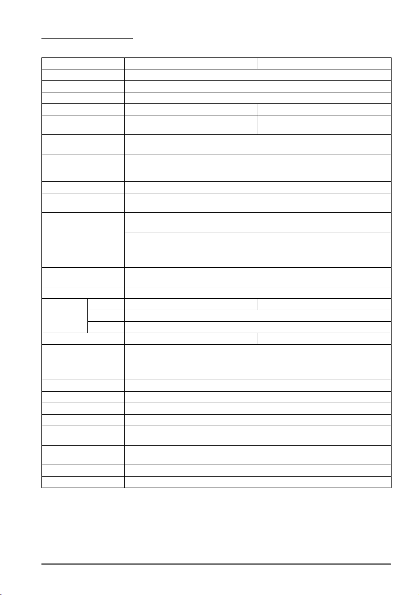
Specifications
80 mm paper width 58 mm paper width
Printing method Thermal line printing
Dot density 180 dpi ×180 dpi [dots per 25.4 mm {1"}]
Printing direction Unidirectional with friction feed
Printing width 72 mm {2.83"}, 512 dot positions 50.8 mm {2.0"}, 360 dot positions
Characters per line
(default)
Character spacing
(default)
Character size Standard/Double-height/Double-width/Double-width and Double-height
Character structure Font A (default): 12 × 24; Font B: 9 × 17 (including 2-dot horizontal spacing)
Number of characters Alphanumeric characters: 95; International character sets: 18 sets
Printing speed 300 mm/s {11.8"/s} max.; 70.9 lps (4.23 mm {1/6"} feed)
Paper feed speed Approx. 200 mm/s {approx. 7.9"/s}
Line spacing (default) 4.23 mm {1/6"}
Roll paper
(single-ply)
Thermal paper type NTP080-80 NTP058-80
Interface (compatible) Serial (RS-232)/Parallel (IEEE1284)/Ethernet (10BASE-T/100BASE-TX)/
Receive buffer 4KB/45 bytes
Cash drawer function 2 drives
Supply voltage*
Current consumption Mean: Approx. 1.8A
Temperature Operating: 5 to 45°C {41 to 113°F}
Humidity Operating: 10 to 90% RH
Overall dimensions 148 × 145 × 195 mm {5.83 × 5.71 × 7.68"} (H × W × D)
Weight (mass) Approx. 1.6 kg {3.5 lb}
lps: lines per second dpi: dots per 25.4 mm (dots per inch)
*1: The values are those when the paper width is changed to 58 mm by installing the roll paper guide
and making the paper width setting with utility software for the TM-T88V. The roll paper guide may
not be included depending on the printer model.
*2: Be sure to use a safety-standards-applied power source that meets the following specifications.
Rated output: 24 V/2.0 A or more, Maximum output: 240 VA or less
Width 79.5 mm ± 0.5 mm {3.13" ± 0.02"} 57.5 mm ± 0.5 mm {2.26" ± 0.02"}
Diameter Maximum outside diameter: 83 mm {3.27"}
Spool Spool diameter: Inside: 12 mm {0.47"}; Outside: 18 mm {0.71"}
Font A: 42; Font B: 56 Font A: 30; Font B: 40
Font A: 0.28 mm {.01"} (2 dots), Font B: 0.28 mm {.01"} (2 dots)
Font A: 1.41 × 3.39/1.41 × 6.77/2.82 × 3.39/2.82 × 6.77 mm
Font B: 0.99 × 2.40/0.99 × 4.80/1.98 × 2.40/1.98 × 4.80 mm
Extended graphics: 128 × 43 pages (including user-defined page)
Ladder bar code and 2D code: 100 mm/s {2.4"/s}
The above speed values are approximate.
The values are when the printer prints with density “Normal” at 24 V and 25°C {77°F}
Speed is adjusted automatically depending on the voltage applied and head
temperature.
(continuous paper feed with the Feed button.)
Wireless LAN (IEEE802.11b)/USB [Compliance: USB 2.0, Communication speed:
Full-speed (12 Mbps)]/USB Plus Power [Communication speed: Full-speed (12
Mbps)]
2
DC + 24 V ± 7%
Storage: –10 to 50°C {14 to 122°F}, except for paper
Storage: 10 to 90% RH, except for paper
*1
ix

English
Standards and Approvals
The following standards are applied only to the printers that are so labeled. (EMC is tested using the
Epson power supplies.)
Europe: CE marking
North America: FCC/ICES-003 Class A
Oceania: AS/NZS CISPR22 Class A
The connection of a non-shielded printer interface cable to this printer will invalidate the EMC standards
of this device. You are cautioned that changes or modifications not expressly approved by Seiko Epson
Corporation could void your authority to operate the equipment.
CE Marking
WARNING
The printer conforms to the following Directives and Norms:
Directive 2004/108/EC
EN 55022 Class A
EN 55024
IEC 61000-4-2 IEC 61000-4-5
IEC 61000-4-3 IEC 61000-4-6
IEC 61000-4-4 IEC 61000-4-11
FCC Compliance Statement For American Users
This equipment has been tested and found to comply with the limits for a Class A digital device, pursuant
to Part 15 of the FCC Rules. These limits are designed to provide reasonable protection against harmful
interference when the equipment is operated in a commercial environment.
This equipment generates, uses, and can radiate radio frequency energy and, if not installed and used in
accordance with the instruction manual, may cause harmful interference to radio communications.
Operation of this equipment in a residential area is likely to cause harmful interference, in which case the
user will be required to correct the interference at his own expense.
For Canadian Users
This Class A digital apparatus complies with Canadian ICES-003.
Indication of the manufacturer and the importer in accordance
with requirements of directive 2011/65/EU (RoHS)
Manufacturer: SEIKO EPSON CORPORATION
Address: 3-5, Owa 3-chome, Suwa-shi, Nagano-ken 392-8502, Japan
Telephone: 81-266-52-3131 Fax: 81-266-52-8409
Importer: EPSON EUROPE B.V.
Address: Azië building, Atlas ArenA, Hoogoorddreef 5, 1101 BA Amsterdam Zuidoost, The Netherlands
Telephone: 31-20-314-5000
x

English
English
User’s Manual
DIP Switch Tables and Specifications
The DIP switch tables and technical specifications are at the beginning of this manual.
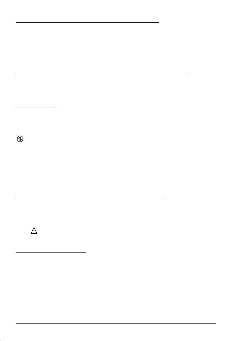
Illustrations
All of the illustrations are at the beginning of this manual. They are identified by letters (A, B, C . . .). Some
of the illustrations have numbers in them. See the list below for the meaning of the numbers.
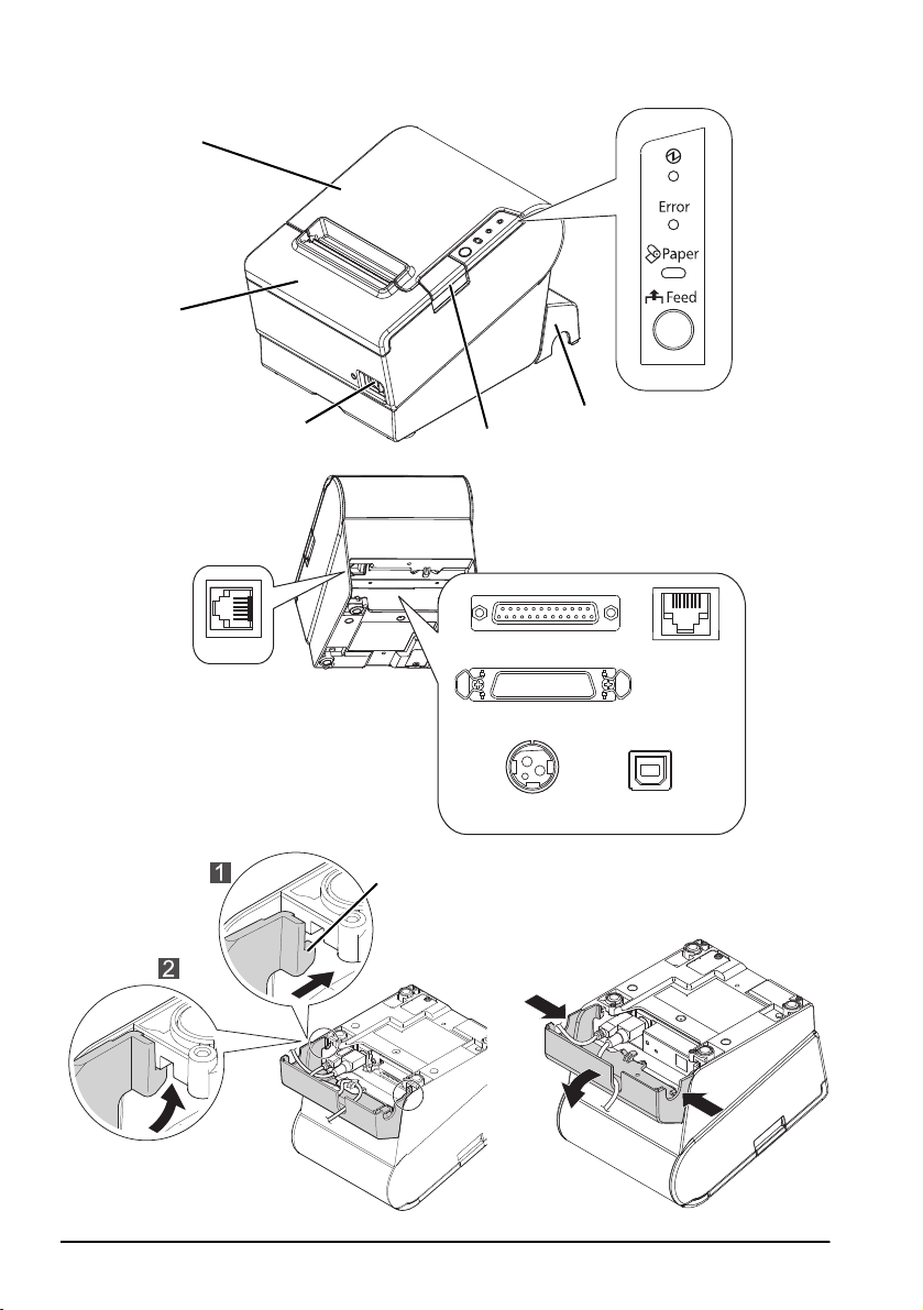
Illustration A: Illustration C:
1. Roll paper cover 7. Hook
2. Cutter cover Illustration N:
3. Power switch 8. Hole
4. Cover open button Illustration O:
5. Connector cover 9. Sheets for 58 mm paper width
6. Control panel
All rights reserved. No part of this publication may be reproduced, stored in a retrieval system, or transmitted in
any form or by any means, electronic, mechanical, photocopying, recording, or otherwise, without the prior
written permission of Seiko Epson Corporation. No patent liability is assumed with respect to the use of the
information contained herein. While every precaution has been taken in the preparation of this book, Seiko Epson
Corporation assumes no responsibility for errors or omissions. Neither is any liability assumed for damages
resulting from the use of the information contained herein.
Neither Seiko Epson Corporation nor its affiliates shall be liable to the purchaser of this product or third parties
for damages, losses, costs, or expenses incurred by purchaser or third parties as a result of: accident, misuse, or
abuse of this product or unauthorized modifications, repairs, or alterations to this product, or (excluding the U.S.)
failure to strictly comply with Seiko Epson Corporation’s operating and maintenance instructions.
Seiko Epson Corporation shall not be liable against any damages or problems arising from the use of any options
or any consumable products other than those designated as Original Epson Products or Epson Approved
Products by Seiko Epson Corporation.
Depending on the area, the interface cable may be included with the product. If so, use that cable.
Seiko Epson Corporation shall not be held liable for any damage resulting from electromagnetic
interference that occurs from the use of any interface cables other than those designated as Epson
approved products.
EPSON is a registered trademark of Seiko Epson Corporation in Japan and other countries/regions.
NOTICE: The contents of this manual are subject to change without notice.
Copyright © 2010 by Seiko Epson Corporation, Nagano, Japan.
This is a Class A product. In a domestic environment this product may cause radio interference in which
case the user may be required to take adequate measures.
WARNING
TM-T88V User’s Manual 1

English
Important Safety Information
This section presents important information intended to ensure safe and effective
use of this product. Read this section carefully and store it in an accessible
location.
Key to Symbols
The symbols in this manual are identified by their level of importance, as defined
below. Read the following carefully before handling the product.
WARNING:
Warnings must be followed carefully to avoid serious bodily injury.
CAUTION:
Cautions must be observed to avoid minor injury to yourself, damage to your
equipment, or loss of data.
Safety Precautions
WARNING:
Shut down your equipment immediately if it produces smoke, a strange odor, or
unusual noise. Continued use may lead to fire. Immediately unplug the
equipment and contact your dealer or a Seiko Epson service center for advice.
Never attempt to repair this product yourself. Improper repair work can be
dangerous.
Never disassemble or modify this product. Tampering with this product may
result in injury or fire.
Be sure to use the specified power source. Connection to an improper power
source may cause fire.
Do not allow foreign matter to fall into the equipment. Penetration by foreign
objects may lead to fire.
If water or other liquid spills into this equipment, unplug the AC cable
immediately, and then contact your dealer or a Seiko Epson service center for
advice. Continued usage may lead to fire.
If you open the DIP switch cover, be sure to close the cover and tighten the
screw after adjusting the DIP switch. Using this product with the cover open
may cause fire or electric shock.
Do not use aerosol sprayers containing flammable gas inside or around this
product. Doing so may cause fire.
Do not connect a telephone line to the drawer kick-out connector; otherwise
the printer and the telephone line may be damaged.
CAUTION:
Do not connect cables in ways other than those mentioned in this manual.
Different connections may cause equipment damage and burning.
Be sure to set this equipment on a firm, stable, horizontal surface. The product
may break or cause injury if it falls.
Do not use in locations subject to high humidity or dust levels. Excessive humidity
and dust may cause equipment damage or fire.
2 TM-T88V User’s Manual

Do not place heavy objects on top of this product. Never stand or lean on this
product. Equipment may fall or collapse, causing breakage and possible injury.
Take care not to injure your fingers on the manual cutter
• When you remove printed paper
• When you perform other operations such as loading/replacing roll
paper
To ensure safety, unplug this product before leaving it unused for an extended
period.
Caution Labels
The caution labels on the product indicate the following precautions.
English
Do not touch the thermal head and the frame on its side because it can be
very hot after printing.
Touching the manual cutter may cause injury.
CAUTION:
CAUTION:
Restriction of Use
When this product is used for applications requiring high reliability/safety, such
as transportation devices related to aviation, rail, marine, automotive, etc.;
disaster prevention devices; various safety devices, etc.; or functional/precision
devices, etc.; you should use this product only after giving consideration to
including fail-safes and redundancies into your design to maintain safety and
total system reliability. Because this product was not intended for use in
applications requiring extremely high reliability/safety, such as aerospace
equipment, main communication equipment, nuclear power control equipment,
or medical equipment related to direct medical care, etc., please make your own
judgment on this product’s suitability after a full evaluation.
Unpacking
The following items are included with the standard specification printer.
If any item is damaged, contact your dealer.
❏ Printer ❑ Roll paper
❏ Connector cover ❑ Power switch cover
❏ Roll paper guide* ❑ Strips for 58 mm paper width × 2*
❏ Screw* ❑ AC adapter*
❏ AC cable* ❑ Warranty certificate*
❏ User’s manual
* May not be included depending on the printer model.
TM-T88V User’s Manual 3
English
Downloading Drivers, Utilities, and Manuals
The latest versions of drivers, utilities, and manuals can be downloaded from one
of the following URLs.
For customers in North America, go to the following web site:
http://www.epsonexpert.com/ and follow the on-screen instructions.
For customers in other countries, go to the following web site:
http://download.epson-biz.com/?service=pos
Precautions When Installing the Power Supply Cover
A description of EMI standards is on the bottom of the printer. When the optional
power supply cover (OT-BX88V) is installed, it is hard to check it. In such case,
uninstall the power supply cover if necessary.
Part Names
See illustration A on page ii and the part names on page 1.
Control Panel
(Power) LED
This LED is on when the printer is on.
Error LED
This indicates an error.
Paper LED
On indicates a paper near end or out. Flashing indicates standby.
Feed button
This button feeds paper.
Installing the Printer Horizontally or Vertically
You can install the printer horizontally on a flat surface (with the paper exit on
top) or vertically (with the paper exit at the front) by hanging it on a wall, using
the optional WH-10 hanging bracket set.
WARNING:
When hanging the printer on the wall with the hanging bracket set, be sure to
attach a connector cover to the printer.
Setting Up the Printer
To set up the printer, follow the steps below.
1. Connect the cables.
2. Attach the connector cover.
3. Arrange the cables.
4. Install the roll paper.
4 TM-T88V User’s Manual

Connecting the Cables
CAUTION:
For a serial interface, use a null modem cable.
For a parallel interface, use an IEEE 1284 cable.
For a USB interface, do not turn on the printer before installing the printer driver.
1. Make sure the printer is turned off.
2. Connect the AC cable and each interface cable to the connectors on the printer
back. For the shape of each connector, see illustration B on page ii. (Mounted
interfaces vary by the printer model.)
3. Connect the interface cable to the computer.
4. Insert the AC cable plug into a power outlet.
Attaching the Connector Cover
Follow the steps below to attach the connector cover to protect the cables.
1. Turn over the printer.
2. Position the two hooks on both sides of the connector cover so that they hook
the printer case, as shown in illustration C on page ii.
3. Push the connector cover down to click onto the printer case.
To remove the connector cover, turn the printer over, and push the connector
cover down while pushing both sides of the connector cover inward to detach the
hooks from the printer case. See illustration D on page ii.
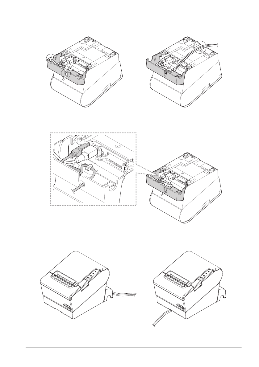
Arranging the Cables
Pass the cables through cable exits in the connector cover. The connector cover has
cable exits on the back and both sides.
You can also route the serial, USB, or power cables out the front by passing them
through the notch in the printer bottom. See illustration E on page iii.
If you want to pass the USB cable through the cable exit on the back, fit the cable
under the hook on the printer to prevent the cable from coming off. See
illustration F.
After the cable arrangement, turn over the printer, and make sure the cables are
not pinched. See illustration G.
English
Installing Roll Paper
Follow the steps below to install the roll paper. If you want to change the paper
width by using the roll paper guide, see “Changing the Paper Width.”
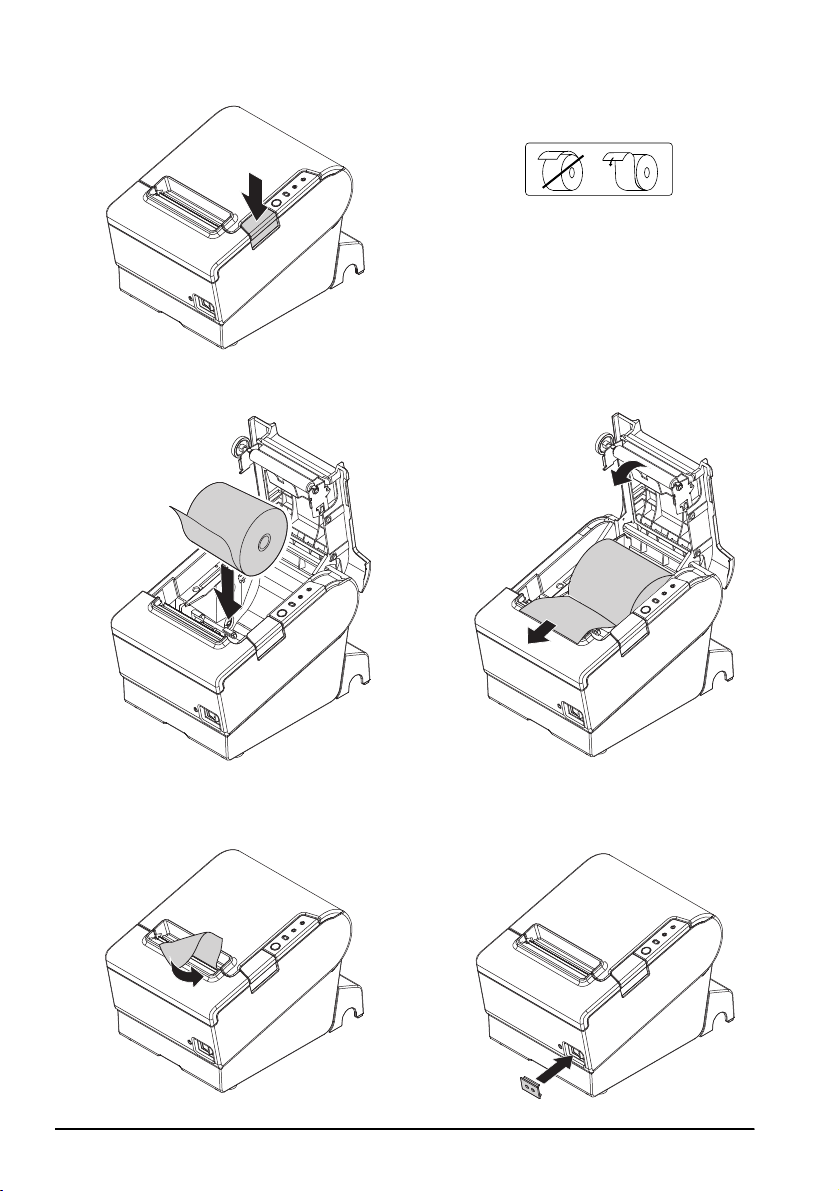
1. Press the cover open button to open the roll paper cover. See illustration H on
page iv.
2. Remove the used roll paper core if any, and insert the roll paper. See
illustration J. The correct direction of the paper is shown in illustration I.
3. Pull out some paper, and close the roll paper cover, as shown in illustration K.
4. Tear off the paper, as shown in illustration L.
TM-T88V User’s Manual 5

English
Attaching the Power Switch Cover
The enclosed power switch cover ensures that the power switch is not pressed
accidentally.
You can turn on and off the power switch by inserting a sharp-pointed object in
the holes in the power switch cover. To detach the cover, use a sharp-pointed
object.
To use this cover, install it as shown in illustration M on page iv.
WARNING:
If an accident occurs with the power switch cover attached, unplug the AC
cable immediately. Continued use may cause fire or shock.
Changing the Paper Width
If a roll paper guide is included with your printer, you can change the paper
width from 80 mm to 58 mm by installing the roll paper guide. Follow the steps
below to change the paper width.
CAUTION:
If you once change the paper width from 80 mm to 58 mm, you cannot
change it back to 80 mm.
When changing the paper width, be sure to make the setting for the paper
width with utility software for the TM-T88V.
1. Open the roll paper cover.
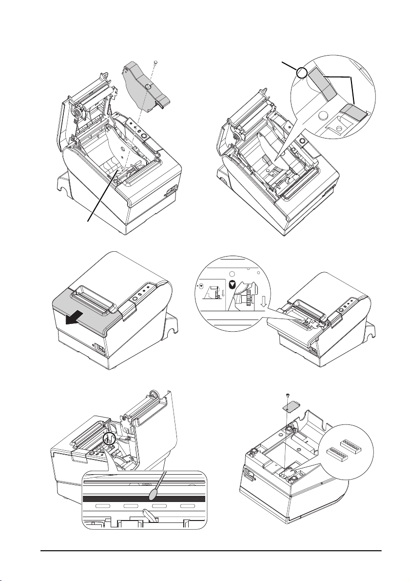
2. Install the roll paper guide so that the projection on its bottom is aligned with
the hole at the right of the roll paper holder, as shown in illustration N on
page v.
3. Tighten the enclosed screw to fix the roll paper guide.
4. Paste the enclosed 2 strips along the roll paper guide on the bottom of the roll
paper holder, as shown in illustration O.
Make sure the space between the top edge of strip and the line of the groove
in the roll paper guide (indicated as a in the illustration) is 0.5 mm or less.
5. Install the roll paper correctly.
6. Close the roll paper cover.
Troubleshooting
No lights on the control panel
Check whether the DC cable and AC cable are correctly connected to the printer
and the power outlet.
Error LED on with no printing
❏ Check whether the roll paper cover is closed. If it is open, close it.
❏ If the Paper LED is on, check whether the roll paper is correctly installed and
any roll paper remains.
6 TM-T88V User’s Manual

Error LED flashing with no printing
❏ Check whether a paper jam has occurred. If paper is jammed, remove the
jammed paper referring to the description below and install the roll paper
correctly.
❏ Printing stops if the head overheats and resumes automatically when it cools.
❏ For other cases, turn the printer off, and after 10 seconds, back on.
Removing Jammed Paper
When a paper jam occurs, never pull out the paper forcibly. Open the roll paper
cover and remove the jammed paper.
English
Do not touch the thermal head and the frame on its side (indicated in the circle
in illustration R on page v) because it can be very hot after printing.
If the roll paper cover does not open, follow the steps below.
1. Turn off the printer.
2. Slide the cutter cover toward the front to open it, as shown in illustration P on
3. Turn the knob until you see a triangle in the opening. This returns the cutter
4. Close the cutter cover.
5. Open the roll paper cover and remove the jammed paper.
CAUTION:
page v.
blade to the normal position. There is a label near the cutter to assist you. See
illustration Q.
Cleaning
Cleaning the Printer Case
Be sure to turn off the printer, and wipe the dirt off the printer case with a dry
cloth or a damp cloth.
CAUTION:
Never clean the product with alcohol, benzine, thinner, or other such solvents.
Doing so may damage or break the parts made of plastic and rubber.
Cleaning the Thermal Head
After printing, the thermal head and the frame on its side (indicated in the
circle in illustration R on page v) can be very hot. Be careful not to touch it and
to let it cool before you clean it. Do not damage the thermal head by touching
it with your fingers or any hard object.
Turn off the printer, open the roll paper cover, and clean the thermal elements of
the thermal head with a cotton swab moistened with an alcohol solvent (ethanol
or IPA). See illustration R on page v.
Epson recommends cleaning the thermal head periodically (generally every
3 months) to maintain receipt print quality.
CAUTION:
TM-T88V User’s Manual 7

English
Setting the DIP Switches
CAUTION:
Be sure to turn off the printer before removing the cover of the DIP switches.
Removing it while the printer is turned on may cause problems such as an
electric short, which leads to a malfunction of the printer.
1. Turn off the printer.
2. Turn over the printer.
3. Remove the DIP switch cover by removing the screw, as shown in illustration
S on page v.
4. Set the DIP switches using a fine-tipped tool.
5. Replace the DIP switch cover, and fix it by installing the screw.
The new setting becomes effective after the printer is turned on.
8 TM-T88V User’s Manual

English
Français
Manuel de l’utilisateur
Tableaux et spécifications de micro-interrupteurs DIP
Les tableaux et spécifications techniques de micro-interrupteurs DIP figurent au début de ce manuel.
Illustrations
Toutes les illustrations se trouvent au début de ce manuel. Elles sont identifiées par des lettres (A, B, C . . .).
Certaines des illustrations comportent des chiffres. Voir la liste ci-dessous pour la signification de ces
chiffres.
Illustration A: Illustration C:
1. Couvercle du rouleau de papier 7. Crochet
2. Capot du coupe-papier Illustration N:
3. Interrupteur marche-arrêt 8. Trou
4. Bouton d’ouverture du capot Illustration O:
5. Cache-connecteurs 9. Feuilles pour largeur de papier 58 mm
6. Panneau de commande
Tous droits réservés. Sauf autorisation écrite préalable de Seiko Epson Corporation, la reproduction, le stockage
dans un système de rappel de données et la transmission sous quelque forme ou par quelque moyen que ce soit
(électronique, mécanique, par photocopie, enregistrement, etc…) d’une partie quelconque de la présente
publication sont interdits. La société décline toute responsabilité relative à l’exploitation des informations
contenues dans le présent document. Cet ouvrage a été rédigé avec le plus grand soin ; toutefois, Seiko Epson
décline toute responsabilité pour les erreurs et omissions qu’il pourrait contenir, ainsi que pour tous dommages
résultant de l’exploitation des informations qu’il contient.
La responsabilité de Seiko Epson Corporation ou de ses filiales ne saurait être engagée envers l’acheteur de ce
produit ou envers des tiers pour dommages, pertes, frais ou débours encourus par ceux-ci par suite d’accident ou
d’utilisation erronée ou abusive de ce produit, de modification, réparation ou transformation non autorisé de
celui-ci, ou (à l’exclusion des Etats-Unis), de toute utilisation du produit qui n’est pas strictement conforme aux
instructions d’utilisation et de maintenance de Seiko Epson Corporation.
Seiko Epson Corporation décline toute responsabilité pour dommages ou problèmes découlant de l’utilisation de
tous articles en option ou de toutes fournitures consommables autres que celles désignée produit d’origine Epson
ou produit approuvé Epson par Seiko Epson Corporation.
EPSON est une marque déposée de Seiko Epson Corporation au Japon et dans d’autres pays/régions.
REMARQUE : Les informations contenues dans ce manuel sont sujettes à modification sans préavis.
Copyright © 2010 par Seiko Epson Corporation, Nagano, Japon.
AVERTISSEMENT
Cet appareil est un produit de classe A. Dans un environnement résidentiel, il risque de provoquer un
brouillage radio, auquel cas l’utilisateur pourra être tenu de prendre des mesures adéquates.
À l’intention des utilisateurs canadiens
Cet appareil numérique de classe A est conforme à la norme canadienne NMB-003.
TM-T88V Manuel de l’utilisateur 9

English
Importantes précautions de sécurité
D'importantes informations destinées à assurer un emploi sans danger et efficace
de ce produit sont présentées dans cette section. Lisez-la attentivement et rangezla dans un endroit facile d'accès.
Signification des symboles
Dans ce manuel, les symboles sont identifiés par ordre d’importance de la manière
indiquée ci-après. Lisez attentivement ce qui suit avant de manipuler le produit.
AVERTISSEMENT :
Respectez strictement les avertissements afin d’éviter tout risque de blessure
grave.
ATTENTION :
Les mises en garde doivent être respectées afin d’éviter les risques de blessure
légère de l’utilisateur, d’endommagement du matériel ou de perte de données.
Consignes de sécurité
AVERTISSEMENT :
Mettez immédiatement l’équipement hors tension s’il dégage de la fumée ou
une odeur étrange ou s’il émet des bruits inhabituels. En persistant à l’utiliser
dans ces circonstances, un incendie pourrait se produire. Débranchez
immédiatement l’équipement et contactez votre distributeur ou un centre de
service Seiko Epson pour demander conseil.
N’essayez jamais de réparer ce produit vous-même. Toute réparation erronée
peut être dangereuse.
Ne démontez et ne modifiez jamais ce produit. Les interventions intempestives
peuvent provoquer des blessures ou des incendies.
Vérifiez que la source d’alimentation électrique est conforme aux
spécifications. Toute connexion à une source d’alimentation non conforme
peut provoquer un incendie.
Ne laissez pas tomber de corps étrangers dans l’équipement. La pénétration
de corps étrangers peut provoquer un incendie.
En cas de pénétration d’eau ou d’un autre liquide renversé dans l’équipement,
débranchez immédiatement le cordon d’alimentation et contactez votre
distributeur ou un centre de service Seiko Epson pour demander conseil. En
persistant à utiliser l’équipement dans ces circonstances, un incendie pourrait
se produire.
Si le cache du micro-interrupteur DIP est ouvert, assurez-vous de le fermer et de
bien serrer la vis après avoir réglé le micro-interrupteur. L’utilisation de ce
produit avec le cache ouvert peut provoquer un incendie ou un choc
électrique.
N’utilisez pas de bombes à aérosol contenant un gaz inflammable à l’intérieur
ou à proximité de ce produit. Cela pourrait entraîner un incendie.
Ne pas brancher de ligne téléphonique sur le connecteur d’ouverture
automatique du tiroir car cela risquerait d’endommager l’imprimante et la
ligne téléphonique.
10 TM-T88V Manuel de l’utilisateur

ATTENTION :
Conformez-vous strictement aux instructions relatives à la connexion de câbles
du présent manuel. Tout écart peut provoquer l’endommagement de
l’équipement ou un incendie.
Veillez à poser cet équipement sur une surface horizontale ferme et stable.
Toute chute du produit peut casser celui-ci ou occasionner des blessures.
N’utilisez pas le produit dans des endroits très poussiéreux ou exposés à une
forte humidité. Toute humidité ou poussière excessive peut provoquer
l’endommagement de l’équipement ou un incendie.
Ne posez pas d’objets lourds sur ce produit. Ne vous y appuyez jamais et ne
montez jamais dessus. L’équipement pourrait tomber ou s’affaisser, et se casser
ou causer des blessures.
Prenez garde de ne pas vous couper les doigts avec le coupe-papier manuel
• En retirant le papier imprimé
• Lors d’autres opérations comme le chargement/remplacement du
rouleau de papier
Pour plus de sécurité, débranchez ce produit lorsqu’il ne doit pas servir pendant
une période prolongée.
Étiquettes de mise en garde
Les étiquettes de mise en garde sur le produit indiquent les précautions suivantes.
English
Ne touchez pas la tête thermique ou son cadre car elle peut être très chaude
après une impression.
ATTENTION :
ATTENTION :
Toucher le coupe-papier peut entraîner des blessures.
Restrictions d’emploi
En cas d’utilisation de ce produit pour des applications exigeant une grande
fiabilité/sécurité, telles qu’appareils employés en transport aérien, ferroviaire,
maritime, automobile, etc., appareils de prévention des catastrophes, divers
appareils de sécurité, etc., ou appareils de fonction/précision, vous devrez, avant
d’utiliser ce produit, considérer l’incorporation à votre système de dispositifs de
sécurité positive et de moyens redondants assurant la sécurité et la fiabilité de
l’ensemble du système. Étant donné que ce produit n’est pas destiné aux
applications exigeant une fiabilité/sécurité extrême, telles que matériel
aérospatial, matériel de communications principal, matériel de commande
nucléaire ou matériel de soins médicaux directs, etc., vous devrez, après totale
évaluation, décider si ce produit convient.
TM-T88V Manuel de l’utilisateur 11

English
Déballage
Les éléments suivants sont fournis avec l’imprimante standard.
Contacter le revendeur si l’un d’entre eux est endommagé.
❏ Imprimante ❑ Rouleau de papier
❏ Cache de connecteur ❑ Cache d’interrupteur
❏ Capot du rouleau de papier*❑ Feuilles pour largeur de papier 58 mm × 2*
❏ Vis* ❑ Adaptateur secteur*
❏ Câble secteur* ❑ Certificat de garantie*
❏ Manuel de l’utilisateur
* Peut ne pas être compris selon le modèle d’imprimante.
Téléchargement des pilotes, utilitaires et manuels
Il est possible de télécharger les dernières versions des pilotes, utilitaires et
manuels à partir de l’une des URL suivantes.
En Amérique du Nord, accédez au site web suivant :
http://www.epsonexpert.com/ et suivez les instructions qui s’affichent à l’écran.
Dans les autres pays, accédez au site web suivant :
http://download.epson-biz.com/?service=pos
Précautions à suivre lors de l’installation du couvercle
d’alimentation
Une description des normes EMI figure sur le dessous de l’imprimante. Lorsque le
couvercle d’alimentation optionnel (OT-BX88V) est installé, cette description est
difficile à voir. Dans ce cas, retirez le couvercle d’alimentation le cas échéant.
Désignations des éléments
Reportez-vous à l’illustration A de la page ii et aux désignations des éléments de
la page 9.
Panneau de commande
Voyant d'alimentation
Ce voyant s’allume lorsque l’imprimante est en marche.
Voyant d'erreur (Error)
Ce voyant indique une erreur.
Voyant Papier (Paper)
Ce voyant s’allume quand le rouleau de papier arrive ou presque à la fin. Il
clignote pour indiquer que l’imprimante est en mode d’attente.
Bouton d'avance papier (Feed)
Ce bouton sert à faire avancer le papier.
Installation horizontale ou verticale de l’imprimante
L’imprimante peut être installée à l’horizontale sur une surface plane (sortie
papier en haut) ou à la verticale (sortie papier à l’avant) en l’accrochant à un mur
au moyen du jeu de supports muraux WH-10 offert en option.
12 TM-T88V Manuel de l’utilisateur

AVERTISSEMENT :
Lorsque l’imprimante est suspendue au mur avec le jeu de supports muraux,
s’assurer d’installer un cache de connecteur sur l’imprimante.
Installation de l’imprimante
Pour installer l’imprimante, suivez la procédure décrite ci-après :
1. Branchez les câbles.
2. Mettez le cache-connecteurs en place.
3. Arrangez les câbles.
4. Installez le rouleau de papier.
Branchement des câbles
ATTENTION :
Dans le cas d’une interface série, utilisez un câble null modem.
Dans le cas d’une interface parallèle, utilisez un câble IEEE 1284.
Dans le cas d’une interface USB, ne pas mettre l’imprimante sous tension avant
d’avoir installé le pilote correspondant.
1. Assurez-vous que l’imprimante est hors tension.
2. Branchez le cordon d’alimentation et le câble de chaque interface aux
connecteurs situés à l’arrière de l’imprimante. Pour connaître la forme de
chaque connecteur, reportez-vous à l’illustration B de la page ii.
(Les interfaces montées varient selon le modèle d’imprimante.)
3. Reliez le câble de l’interface à l’ordinateur.
4. Branchez le cordon d’alimentation à une prise électrique.
English
Fixation du cache-connecteurs
Suivez la procédure décrite ci-après pour fixer le cache-connecteurs protégeant les
câbles.
1. Retournez l’imprimante.
2. Placez les deux crochets de chaque côté du cache de sorte à les fixer au boîtier
de l’imprimante, comme indiqué dans l’illustration C de la page ii.
3. Abaissez le cache-connecteurs jusqu’à ce qu’il se clipse au boîtier de
l’imprimante.
Pour enlever le cache de connecteur, retourner l'imprimante, et pousser le cache
de connecteur vers le bas, tout en poussant les deux côtés du connecteur vers
l'intérieur pour décrocher les crochets du boîtier de l'imprimante. Voir
l’illustration D de la page ii.
Arrangez les câbles
Passez les câbles dans les sorties correspondantes du cache-connecteurs. Le cacheconnecteurs dispose de sorties de câble à l’arrière et sur les deux côtés.
Vous pouvez également acheminer le câble série, le câble USB et le câble
d’alimentation en les faisant passer par l’encoche au bas de l’imprimante. Voir
l’illustration E de la page iii.
TM-T88V Manuel de l’utilisateur 13

English
Si vous souhaitez faire passer le câble USB dans la sortie de câble à l’arrière, fixez
le câble sous le crochet de l’imprimante pour l’empêcher de se détacher. Voir
l’illustration F.
Après l’arrangement des câbles, retournez l’imprimante et vérifiez que les câbles
ne sont pas trop serrés. Voir l’illustration G.
Installation du rouleau de papier
Suivez la procédure décrite ci-après pour installer le rouleau de papier. Si vous
souhaitez modifier la largeur du papier à l’aide du guide du rouleau de papier,
reportez-vous à la section “Modification de la largeur du papier.”
1. Appuyez sur le bouton du couvercle du rouleau de papier pour ouvrir celui-
ci. Reportez-vous à l’illustration H de la page iv.
2. Retirez le cylindre du rouleau de papier épuisé le cas échéant puis insérez le
rouleau de papier. Reportez-vous à l’illustration J. Le sens d’insertion du
papier est indiqué dans l’illustration I.
3. Tirez un peu de papier et refermez le couvercle du rouleau de papier comme
indiqué dans l’illustration K.
4. Déchirez le papier, comme indiqué dans l’illustration L.
Fixation du cache de l’interrupteur marche-arrêt
Le cache d'interrupteur fourni empêche tout actionnement accidentel de
l'interrupteur marche-arrêt.
Vous pouvez actionner l’interrupteur marche-arrêt en insérant un objet pointu
dans les orifices du cache de l’interrupteur marche-arrêt. Pour retirer le cache,
utilisez également un objet pointu.
Pour utiliser ce cache, installez-le comme indiqué dans l’illustration M de la page
iv.
AVERTISSEMENT :
En cas d’accident alors que le cache d’interrupteur est en place, débrancher
immédiatement le cordon d’alimentation. Il existe sinon des risques d’incendie
ou de choc électrique.
Modification de la largeur du papier
Si le guide du rouleau de papier est fourni, vous pouvez passer d’un modèle
d’imprimante de 80 mm de largeur de papier à un modèle d’imprimante de 58
mm en installant le guide du rouleau de papier. Suivez les étapes suivantes pour
changer la largeur du papier.
ATTENTION :
Après avoir changé la largeur du papier de 80 à 58 mm, vous ne pouvez plus la
changer de 58 à 80 mm.
Si vous modifiez la largeur du papier, veillez à paramétrer la largeur de papier à
l’aide des boutons Memory. Pour paramétrer les boutons Memory, utilisez
l’utilitaire de la TM-T88V.
1. Ouvrez le couvercle du rouleau de papier.
14 TM-T88V Manuel de l’utilisateur

2. Placez le guide du rouleau de papier de sorte que l’ergot à sa base soit aligné
avec le trou situé à droite du porte-rouleau, comme indiqué dans l’illustration
N de la page v.
3. Serrez la vis fournie pour fixer le guide du rouleau de papier.
4. Collez les deux feuilles fournies le long du guide à la base du porte-rouleau,
comme indiqué dans l’illustration O.
Assurez-vous que l’espace entre le côté supérieur de la feuille et la ligne de la
rainure dans le guide du rouleau de papier (indiqués comme a dans
l’illustration) ne dépasse pas 0,5 mm.
5. Installer correctement le rouleau de papier.
6. Refermez le couvercle du rouleau de papier.
Dépannage
Aucun témoin du panneau de commande ne s'allume
Vérifiez que le câble d’alimentation est relié à l’imprimante et à une prise
électrique.
Voyant d'erreur (Error) allumé en l’absence d’impression
❏ Vérifiez que le couvercle du rouleau de papier est fermé. S’il est ouvert,
fermez-le.
❏ Si le voyant Papier (Paper) est allumé, vérifiez que le rouleau de papier est
placé correctement et qu’il reste du papier.
Voyant d'erreur (Error) clignotant en l’absence d’impression
❏ Vérifiez qu’il n’y a pas de bourrage papier. Si du papier est coincé, retirez-le
en suivant la procédure décrite ci-après et placez correctement le rouleau de
papier.
❏ L’impression s’arrête si la tête surchauffe puis reprend une fois que celle-ci a
refroidi.
❏ Si aucune surchauffe n’est à l’origine de l’arrêt, mettez l’imprimante hors
tension, patientez 10 secondes, puis remettez-la sous tension.
English
Dégagement d’un bourrage de papier
En cas de bourrage de papier, ne retirez jamais le papier en exerçant une
quelconque force. Ouvrez le couvercle du rouleau de papier et retirez le papier à
l’origine du bourrage.
Ne touchez pas la tête thermique ou son cadre (indiqué par le cercle dans
l’illustration R de la page v) ar elle peut être très chaude après une impression.
Si le couvercle du rouleau de papier ne s’ouvre pas, suivez la procédure décrite ciaprès :
1. Mettez l’imprimante hors tension.
2. Faites glisser le capot du coupe-papier vers l’avant pour l’ouvrir comme
ATTENTION :
indiqué dans l’illustration P de la page v.
TM-T88V Manuel de l’utilisateur 15

English
3. Tourner le bouton jusqu'à ce qu'un triangle apparaisse dans l'orifice. Ceci
remet la lame du coupe-papier en place à sa position normale. Au besoin,
consulter l'étiquette apposée près du coupe-papier. Voir l'illustration Q.
4. Refermer le capot du coupe-papier.
5. Ouvrir le capot du rouleau de papier et retirer le papier à l’origine du
bourrage.
Nettoyage
Nettoyage du boîtier de l’imprimante
Assurez-vous de mettre l’imprimante hors tension et essuyez la saleté qui
recouvre le boîtier de l’imprimante avec un chiffon sec ou humide.
ATTENTION :
Ne nettoyez jamais le produit avec de l’alcool, du benzène, du diluant ou tout
autre solvant de ce type.
Cela pourrait endommager ou casser les éléments composés de plastique ou
de caoutchouc.
Nettoyage de la tête thermique
Après une impression, la tête thermique et son cadre (indiqué par le cercle
dans l’illustration R de la page v) peuvent être très chauds. Veillez à ne pas
toucher la tête thermique et à la laisser refroidir avant de la nettoyer. Évitez de
la manipuler avec vos doigts ou un objet dur afin de ne pas l’endommager.
Mettre l’imprimante hors tension, ouvrir le capot du rouleau de papier, et nettoyer
les éléments thermiques de la tête d’impression avec un coton-tige humecté d’un
solvant à l’alcool (éthanol ou alcool isopropylique). Reportez-vous à l’illustration
R de la page v.
Epson recommande de nettoyer la tête thermique à intervalles réguliers (tous les
trois mois généralement) afin de maintenir la qualité d’impression des reçus.
ATTENTION :
Installation des micro-interrupteurs DIP
ATTENTION :
Veillez à mettre l’imprimante hors tension avant de retirer le cache des microinterrupteurs DIP. Si vous le retirez alors que l’imprimante est sous tension, des
problèmes tels qu’un court-circuit peuvent se produire, provoquant un
dysfonctionnement de l’imprimante.
1. Mettez l’imprimante hors tension.
2. Retournez l’imprimante.
3. Retirez le cache des micro-interrupteurs DIP en déposant la vis comme
indiqué dans l’illustration S de la page v.
4. Installez les micro-interrupteurs DIP à l’aide d’un outil à pointe fine.
5. Replacez le cache des micro-interrupteurs DIP et fixez-le à l’aide de la vis.
Cette installation sera prise en compte après une remise sous tension de
l’imprimante.
16 TM-T88V Manuel de l’utilisateur

English
Português
Manual do utilizador
Tabelas e especificações dos comutadores DIP
As tabelas e especificações técnicas dos comutadores DIP encontram-se na parte inicial deste manual.
Ilustrações
Todas as ilustrações encontram-se na parte inicial deste manual. Identificam-se com letras (A, B, C . . .).
Algumas contêm números. Consulte a relação abaixo para obter o significado dos números.
Ilustração A: Ilustração C:
1. Tampa do papel em rolo 7. Gancho
2. Tampa do cortador Ilustração N:
3. Interruptor de alimentação 8. Orifício
4. Botão para a abertura da tampa Ilustração O:
5. Tampa do conector 9. Folhas para 58 mm de largura do papel
6. Painel de controlo
Todos os direitos reservados. Esta publicação não pode ser integral ou parcialmente reproduzida, arquivada nem
transmitida por meio de fotocópias, gravação ou qualquer outro sistema mecânico ou electrónico, sem a prévia
autorização por escrito da Seiko Epson Corporation, que não assume qualquer responsabilidade de patente no
que diz respeito ao uso das informações aqui contidas. Uma vez que foram tomadas todas as precauções na
elaboração deste manual, a Seiko Epson Corporation não se responsabiliza por erros ou omissões, nem por
quaisquer danos resultantes do uso das informações aqui contidas.
O comprador deste produto ou terceiros não podem responsabilizar a Seiko Epson Corporation, ou as suas filiais,
por quaisquer danos, perdas, custos ou despesas, incorridos por ele ou por terceiros, resultantes de acidentes,
abusos ou má utilização do produto, de modificações não autorizadas, reparações ou alterações do produto, ou
resultantes ainda da inobservância estrita das instruções de utilização e manutenção estabelecidas pela Seiko
Epson Corporation.
A Seiko Epson Corporation não se responsabiliza por quaisquer avarias ou problemas provocados pela utilização
de opções ou produtos não reconhecidos como sendo produtos genuínos Epson ou produtos aprovados pela
Epson.
EPSON é marca registada da Seiko Epson Corporation no Japão e noutros países/regiões.
AVISO: O conteúdo deste manual está sujeito a alterações sem aviso prévio.
Copyright © 2010, pela Seiko Epson Corporation, Nagano, Japão.
IMPORTANTE
Este é um produto de Classe A. Num ambiente doméstico, este produto poderá causar interferência de
rádio. Nesse caso, o utilizador poderá ter de tomar medidas adequadas.
TM-T88V Manual do utilizador 17

English
Informações de Segurança Importantes
Esta secção apresenta informações importantes cuja finalidade é garantir uma
utilização segura e eficaz deste produto. Leia esta secção com atenção e guarde-a
num local de fácil acesso.
Significado dos Símbolos
Os símbolos que aparecem neste manual são identificados pelo seu grau de
importância, como se explica abaixo. Leia esta secção com atenção antes de
manusear o produto.
ATENÇÃO:
Cuidados que deve ter para evitar lesões físicas graves.
IMPORTANTE:
Cuidados que deve ter para evitar lesões físicas secundárias, danos ao
equipamento ou perda de dados.
Precauções de Segurança
ATENÇÃO:
Se o equipamento emitir fumo, um odor estranho ou um ruído invulgar,
desligue-o imediatamente. Se o continuar a utilizar, poderá provocar um
incêndio. Desligue imediatamente o equipamento da tomada e contacte o
seu vendedor ou o Serviço de Assistência a Clientes Seiko Epson.
Nunca tente reparar este produto por si próprio. O trabalho de reparação
inadequado pode ser perigoso.
Nunca desmonte ou modifique este produto. Alterar este produto pode
resultar em danos ou incêndio.
Certifique-se de que utiliza a fonte de alimentação indicada. A ligação a uma
fonte de alimentação inadequada pode causar incêndio.
Não deixe cair objectos estranhos dentro do equipamento. A queda de
objectos estranhos pode provocar um incêndio.
Se derramar água ou outro líquido no equipamento, desligue o cabo de
corrente imediatamente e contacte o Serviço de Assistência a Clientes Seiko
Epson. Se continuar a utilizar o equipamento poderá provocar um incêndio.
Se abrir a tampa do comutador DIP, não se esqueça de a fechar e de apertar
o parafuso depois de ajustar o comutador DIP. A utilização deste produto com
a tampa aberta pode resultar num incêndio ou choque eléctrico.
Não utilize aspersores aerossóis que contenham gás inflamável no interior ou
em torno deste produto. Pois isto pode causar incêndio.
Não ligue uma linha telefónica ao conector de abertura da gaveta; caso
contrário, poderá danificar a impressora e a linha telefónica.
IMPORTANTE:
Não ligue os cabos segundo outras instruções a não ser as mencionadas neste
manual. Diferentes ligações podem danificar ou queimar o equipamento.
Certifique-se de que coloca este equipamento sobre uma superfície firme,
estável e plana. O produto pode partir ou causar danos se cair.
18 TM-T88V Manual do utilizador

Evite locais sujeitos a níveis de humidade elevados e com demasiado pó.
Humidade e pó em excesso podem danificar o equipamento e provocar um
incêndio.
Não coloque objectos pesados em cima deste produto. Não se sente nem se
apoie em cima do produto. O equipamento pode cair ou ceder e partir ou
provocar ferimentos.
Tome cuidado em não ferir os seus dedos no cortador manual
• quando remover papel impresso
• Quando executar outras actividades como carga / substituição de
papel em rolo
Para maior segurança, desligue este produto se não o for utilizar durante um
longo período.
Etiquetas de aviso
As etiquetas de aviso no produto indicam as seguintes precauções.
English
Não toque na cabeça térmica e no quadro do seu lado porque pode estar
muito quente após a impressão.
Tocar no cortador manual pode resultar numa lesão.
IMPORTANTE:
IMPORTANTE:
Restrições quanto à utilização
Quando este produto for utilizado em aplicações que requeiram alta fiabilidade/
segurança, como por exemplo dispositivos de transporte relacionados a aviação,
carris, por via marítima, automotiva, etc.; dispositivos para a prevenção de
desastres; vários dispositivos de segurança, etc.; ou dispositivos funcionais/de
precisão, etc., deve-se utilizá-lo apenas após considerar-se adequadamente a
inclusão de protecção contra falhas e de redundâncias no seu projecto de forma a
manterem-se a segurança e a total fiabilidade do sistema. Como este produto não
se destina à utilização em aplicações que requeiram fiabilidade/segurança
extremamente altas, como equipamentos aeroespaciais, equipamentos de base
para comunicações, equipamentos para o controlo de energia nuclear, ou
equipamentos médicos relacionados a cuidados médicos directos, etc., queira
tomar a sua própria decisão sobre a adequação deste produto após uma avaliação
completa.
Desembalagem
Os itens em baixo estão inclusos com a impressora de especificação standard.
Caso algum item esteja danificado, contacte o seu revendedor.
❏ Impressora ❑ Papel em rolo
❏ Tampa do conector ❑ Tampa do interruptor de alimentação
❏ Guia do papel em rolo* ❑ Folha para 58 mm de largura do papel × 2*
❏ Parafuso* ❑ Adaptador AC*
❏ Cabo AC* ❑ Certificado de garantia*
❏ Manual do utilizador
* Este item pode não estar incluído dependendo do modelo da impressora.
TM-T88V Manual do utilizador 19

English
Download de Controladores, Utilitários e Manuais
O donwload das últimas versões de controladores, utilitários e manuais pode ser
feito a partir de um dos seguintes URLs.
Para clientes na América do Norte, visitar o seguinte sítio Web:
http://www.epsonexpert.com/ e seguir as instruções no écran.
Para clientes noutros países, visitar o seguinte sítio Web:
http://download.epson-biz.com/?service=pos
Nomes das peças
Ver a ilustração A, na página ii e os nomes das peças na página 17.
Painel de controlo
Indicador luminoso de ligação
Este indicador acende quando a impressora está ligada.
Indicador luminoso de erro (Error)
Este indicador assinala um erro.
Indicador luminoso do papel (Paper)
Quando aceso, indica falta de papel ou que o papel está prestes a terminar.
Quando pisca, indica modo de espera.
Tecla de alimentação (Feed)
Esta tecla alimenta o papel.
Instalação da impressora horizontal ou verticalmente
A impressora pode ser instalada horizontalmente sobre uma superfície plana
(com a saída de papel na parte de cima) ou verticalmente (com a saída de papel na
parte frontal) fixando-a a uma parede, utilizando o conjunto opcional de suporte
para fixação WH-10.
ATENÇÃO:
Ao afixar a impressora a uma parede com o conjunto de suporte para
fixação, certifique-se de que afixa uma tampa do conector à impressora.
Configuração da Impressora
De forma a configurar a impressora, siga os passos abaixo:
1. Ligue os cabos.
2. Ligue a tampa do conector.
3. Arranje os cabos.
4. Instale o papel em rolo.
20 TM-T88V Manual do utilizador

Ligação dos Cabos
IMPORTANTE:
Para um interface serial, utilize um cabo de modem nulo.
Para um interface paralelo, utilize um cabo IEEE 1284.
Para um interface USB, não ligue a impressora antes de instalar o driver da
impressora.
1. Certifique-se de que a impressora está desligada.
2. Ligue o cabo de alimentação e cada cabo de interface aos conectores na
traseira da impressora. Para a forma de cada conector, consulte a ilustração B,
na página ii. (As interfaces montadas variam de acordo com o modelo da
impressora.)
3. Ligue o cabo de interface ao computador.
4. Insira a ficha do cabo de alimentação numa tomada.
Anexar a Tampa do Conector
Siga os passos abaixo para anexar a tampa do conector, de forma a proteger os
cabos.
1. Vire a impressora.
2. Posicione os dois ganchos em ambos os lados da tampa do conector para que
suportem a estrutura da impressora, conforme é mostrado na ilustração C, na
página ii.
3. Pressione a tampa do conector para baixo, de modo a que encaixe na
estrutura da impressora.
Para retirar a tampa do conector, vire a impressora, empurre a tampa do conector
para baixo e ao mesmo tempo empurre ambos os lados da tampa do conector para
dentro, de forma que se soltem os ganchos da estrutura da impressora. Consulte a
ilustração D, na página ii.
English
Arranje os Cabos
Passe os cabos através das saídas de cabo na tampa do conector. A tampa do
conector tem saídas de cabo na traseira e em ambos os lados.
Também pode encaminhar os cabos de série, USB ou de alimentação pelo exterior
do lado frontal, passando-os através do entalhe na parte de baixo da impressora.
Consulte a ilustração E, na página iii.
Se quiser passar o cabo USB através da saída de cabo na traseira, prenda o cabo no
gancho da impressora para evitar que o cabo saia. Consulte a ilustração F.
Depois de arranjar o cabo, vire a impressora e certifique-se de que os cabos não
estão comprimidos. Consulte a ilustração G.
TM-T88V Manual do utilizador 21

English
Instalação do papel em rolo
Siga os passos abaixo para instalar o papel em rolo. Se pretender alterar a largura
do papel ao utilizar a guia do papel em rolo, consulte “Alteração da Largura do
Papel.”
1. Pressione o botão de abertura da tampa para abrir a tampa do papel em rolo.
Consulte a ilustração H, na página iv.
2. Remova o core do papel em rolo usado, se for o caso, e insira o papel em rolo.
Consulte a ilustração J. A direcção correcta do papel é mostrada na
ilustração I.
3. Puxe um pouco de papel e feche a tampa do papel em rolo, conforme é
mostrado na ilustração K.
4. Rasgue o papel, como mostra a ilustração L.
Anexar a Tampa do Interruptor de Alimentação
A tampa protegida do interruptor de alimentação assegura que tal interruptor não
será premido acidentalmente.
Pode ligar ou desligar o interruptor de alimentação inserindo um objecto de ponta
afiada nos orifícios da tampa do interruptor de alimentação. Para desmontar a
tampa, utilize também um objecto de ponta afiada.
Para usar esta tampa, instale-a conforme mostra a ilustração M, na página iv.
ATENÇÃO:
Se ocorrer um acidente quando a tampa do interruptor de ligação estiver
instalada, desligue imediatamente o cabo de alimentação. Se não o fizer,
poderá provocar um incêndio ou um choque eléctrico.
Alteração da Largura do Papel
Se a guia do papel em rolo estiver incluída, poderá alterar a impressora do modelo
de largura do papel de 80 mm para o modelo de largura do papel de 58 mm ao
instalar a guia do papel em rolo. Siga os passos abaixo para alterar a largura do
papel.
IMPORTANTE:
Assim que alterar a largura do papel de 80 mm para 58 mm, não poderá voltar
a alterá-la para 80 mm.
Ao alterar a largura do papel certifique-se de fazer a configuração para a
largura do papel com os interruptores de Memória. Para configurar os
interruptores de Memória, utilize software utilitário para a TM-T88V.
1. Abra a tampa do papel em rolo.
2. Instale a guia do papel em rolo de forma a que a projecção na parte inferior
fique alinhada com o orifício à direita do suporte de papel em rolo, como
mostra a ilustração N, na página v.
3. Aperte o parafuso incluído para fixar a guia do papel em rolo.
4. Cole as 2 folhas incluídas ao longo da guia do papel em rolo, na parte de
baixo do suporte do papel em rolo, conforme mostra a ilustração O.
Certifique-se de que o espaço entre o canto superior da folha e a linha da
ranhura na guia do papel em rolo (indicado como a na ilustração) é de 0,5
mm ou menos.
22 TM-T88V Manual do utilizador

5. Instale o papel em rolo correctamente.
6. Feche a tampa do papel em rolo.
Resolução de problemas
Os indicadores luminosos não acendem no painel de controlo
Verifique se o cabo de alimentação eléctrica está correctamente ligado à
impressora e à tomada.
Indicador luminoso de erro ligado sem impressão
❏ Verifique se a tampa do papel em rolo está fechada. Se estiver aberta, feche-a.
❏ Se o indicador luminoso de papel estiver ligado, verifique se o papel em rolo
está correctamente instalado e se fica algum papel em rolo.
Indicador luminoso de erro a piscar sem impressão
❏ Verifique se ocorreu alguma obstrução do papel. Se o papel estiver obstruído,
remova o papel obstruído consultando a descrição abaixo e instale o papel em
rolo correctamente.
❏ A impressão parará se a cabeça sobreaquecer e prosseguirá automaticamente
quando arrefecer.
❏ Para outras situações, desligue a impressora e, após 10 segundos, volte a ligá-
la.
Remoção do Papel Obstruído
Se ocorrer uma obstrução de papel, nunca puxe o papel à força para fora. Abra a
tampa do papel em rolo e remova o papel obstruído.
English
Não toque na cabeça térmica e no quadro do seu lado (indicado no círculo
da ilustração R, na página v) porque pode estar muito quente após a
impressão.
Se a tampa do papel em rolo não se abrir, siga os passos abaixo:
1. Desligue a impressora.
2. Faça deslizar a tampa da cortadora para a frente para abri-la, conforme
3. Mova o botão giratório até ver um triângulo na abertura. Isso fará com que a
4. Feche a tampa do cortador.
5. Abra a tampa do papel em rolo e retire o papel emperrado.
IMPORTANTE:
mostra a ilustração P, na página v.
lâmina do cortador volte à posição normal. Há uma etiqueta perto do
cortador para ajudá-lo. Veja a ilustração Q.
TM-T88V Manual do utilizador 23

English
Limpeza
Limpar a Estrutura da Impressora
Certifique-se de que desliga a impressora, e que limpa o pó da estrutura da
impressora com um pano seco ou húmido.
IMPORTANTE:
Nunca limpe o produto com álcool, benzina, diluente, ou outros solventes
semelhantes. Ao fazer isso, pode danificar ou partir as peças feitas em plástico
e borracha.
Limpeza da Cabeça Térmica
Após a impressão, a cabeça térmica e o quadro do seu lado (indicado no
círculo da ilustração R, na página v) podem estar muito quentes. Tenha o
cuidado de não tocá-la e de deixá-la arrefecer antes da limpeza. Não
danifique a cabeça térmica tocando-a com os dedos ou com um objecto
duro.
Desligue a impressora, abra a tampa do papel em rolo e limpe os elementos
térmicos da cabeça térmica com um bastonete de algodão humedecido com um
solvente à base de álcool (etanol ou IPA). Consulte a ilustração R, na página v.
Para manter a boa qualidade impressão, a Epson aconselha a limpar
periodicamente a cabeça térmica (de três em três meses).
IMPORTANTE:
Configuração dos Comutadores DIP
IMPORTANTE:
Certifique-se de que desliga a impressora antes de remover a tampa dos
comutadores DIP. A remoção da mesma enquanto a impressora está ligada
pode causar problemas, como um curto-circuito, o que pode provocar um
mau funcionamento da impressora.
1. Desligue a impressora.
2. Vire a impressora ao contrário.
3. Remova a tampa do comutador DIP ao remover o parafuso, conforme mostra
a ilustração S, na página v.
4. Configure os comutadores DIP utilizando uma ferramenta de ponta afiada.
5. Substitua a tampa do comutador DIP e fixe-a ao instalar o parafuso.
A nova configuração torna-se efectiva após a ligação da impressora.
24 TM-T88V Manual do utilizador

English
Español
Manual del usuario
Tablas y especificaciones de los interruptores DIP
Las tablas de los interruptores DIP y las especificaciones técnicas se hallan al principio de este manual.
Ilustraciones
Todas las ilustraciones están al principio de este manual. Están identificadas por letras (A, B, C,…).
Algunas de las ilustraciones tienen números en ellas. Vea la lista que sigue para conocer el significado de
los números.
Ilustración A: Ilustración C:
1. Tapa del papel de rollo 7. Gancho
2. Tapa del cortador Ilustración N:
3. Interruptor de alimentación 8. Agujero
4. Botón para abrir la tapa Ilustración O:
5. Tapa del conector 9. Hojas para ancho de papel de 58 mm
6. Panel de control
Se reservan todos los derechos. Ninguna porción de esta publicación podrá reproducirse, guardarse en un
sistema de recuperación de datos o transmitirse en forma o modo alguno, sea electrónico, mecánico, fotocopiado,
grabado o de otra forma, sin el permiso previo y por escrito de Seiko Epson Corporation. No se asume
responsabilidad de patente con respecto al uso de la información contenida aquí. Si bien se han tomado todas las
precauciones en la preparación de este libro, Seiko Epson Corporation no asume ninguna responsabilidad por
errores u omisiones. Tampoco asume responsabilidad alguna que surja por el uso de la información contenida
aquí.
Ni Seiko Epson Corporation ni sus compañías afiliadas serán responsables ante el comprador de este producto o
ante terceros por daños, pérdidas, costos, o gastos incurridos por el comprador o por terceros como resultado de:
accidente, uso indebido, o abuso de este producto o de modificaciones, reparaciones o alteraciones no autorizadas
de este producto, o (excluyendo a los EE.UU.) por no cumplir estrictamente con las instrucciones de operación y
mantenimiento de Seiko Epson Corporation.
Seiko Epson Corporation no será responsable de cualquier daño o problema que surja por el uso de cualquier
opción o producto de consumo que no esté designado como Producto Epson Original o Aprobado por Seiko
Epson Corporation.
EPSON es una marca registrada de Seiko Epson Corporation en Japón y otros países/regiones.
AVISO: El contenido de este manual está sujeto a cambios sin previo aviso.
Copyright © 2010 Seiko Epson Corporation, Nagano, Japón.
ADVERTENCIA
Este es un producto de Clase A. En un ambiente residencial este producto podría causar
radiointerferencias, en cuyo caso el usuario podría verse en la necesidad de tomar las medidas
apropiadas.
TM-T88V Manual del usuario 25

English
Información importante sobre la seguridad
En esta sección se ofrece información importante para asegurar el uso seguro y
eficaz de este producto. Lea esta sección atentamente y guárdela en un lugar
accesible.
Clave de los símbolos
Los símbolos incluidos en este manual se identifican por su nivel de importancia,
como se define a continuación. Lea cuidadosamente lo siguiente antes de utilizar
el producto.
ADVERTENCIA:
Hay que seguir cuidadosamente las advertencias para evitar daños físicos.
PRECAUCIÓN:
Se deben tener en cuenta las precauciones para evitar lesiones menores a su
persona, daños al equipo o pérdida de datos.
Precauciones de Seguridad
ADVERTENCIA:
Apague su equipo de inmediato si éste produce humo, un olor raro, o un ruido
inusual. El seguir utilizándolo podría ocasionar un incendio. Desenchufe el
equipo de inmediato y comuníquese con su distribuidor o con un servicio
técnico Epson.
Nunca trate de reparar este producto usted mismo. Una reparación incorrecta
puede ser peligrosa.
Nunca desmonte o modifique este producto. La manipulación de este
producto puede causar lesiones o un incendio.
Cerciórese de usar la fuente de alimentación eléctrica especificada. La
conexión a una fuente de alimentación eléctrica inadecuada puede causar
un incendio.
No deje que materiales extraños caigan dentro del equipo, ya que podría
provocar un incendio.
Si se derrama agua o algún otro líquido dentro del equipo, desenchufe el
cable eléctrico inmediatamente, y después comuníquese con su distribuidor o
con un servicio técnico Epson. El seguir usándolo podría causar un incendio.
Si abre la tapa de los interruptores DIP, cerciórese de cerrar la tapa y de
apretar el tornillo después de ajustar el interruptor DIP. Si este producto se usa
con la tapa abierta se puede causar un incendio o un cortocircuito.
No utilice aerosoles que contengan gases inflamables dentro o cerca de este
producto. Si lo hace, podría provocar un incendio.
No conecte una línea telefónica al conector de apertura del cajón; si lo hace,
se pueden dañar la impresora y la línea de teléfono.
PRECAUCIÓN:
No conecte los cables en formas que difieran a las mencionadas en este
manual. Conexiones diferentes podrían causar daños e incendios.
26 TM-T88V Manual del usuario

Cerciórese de poner este equipo sobre una superficie firme, estable, horizontal.
El producto se puede romper o causar lesiones si se cae.
No lo use en lugares sujetos a altos niveles de humedad o de polvo. El exceso
de humedad o de polvo podría causar daños o incendios al equipo.
No ponga objetos pesados encima de este producto. Nunca se apoye sobre
este producto. El equipo podría caerse, causando roturas y posibles lesiones.
Tenga cuidado para no lastimarse los dedos con el cortador manual
• Al retirar papeles impresos
• Cuando realice cualquier otra operación, tal como carga/reemplazo
de rollo de papel
Por razones de seguridad, por favor desenchufe este producto antes de
dejarlo sin usar por un largo periodo de tiempo.
Etiquetas de Precaución
Las etiquetas de precaución de este producto indican las siguientes precauciones.
English
No toque el cabezal térmico y ni el marco de su lado ya que pueden estar
muy calientes después de la impresión.
Se puede lastimar si toca el cortador manual.
PRECAUCIÓN:
PRECAUCIÓN:
Restricción en el uso
Cuando este producto se usa en aplicaciones que requieren de alta fiabilidad/
seguridad tales como los dispositivos relacionados con la aviación, los
ferrocarriles, la marina, los automóviles, etc.; los dispositivos de prevención de
desastres; dispositivos varios de seguridad, etc.; o los dispositivos funcionales/de
precisión, etc., usted deberá tener en cuenta los posibles fallos, las redundancias
de su diseño para mantener la seguridad y la fiabilidad total de su sistema.
Debido a que este producto no tuvo el propósito de usarse en aplicaciones que
requieren de una fiabilidad/seguridad sumamente altas tales como los equipos
aeroespaciales, equipos principales de comunicación, equipos de control en
plantas nucleares, o en equipos médicos relacionados con los cuidados médicos
directos, etc., por favor decida usted mismo sobre la adecuación de este producto
después de una evaluación completa.
Desembalaje
Se incluyen los siguientes artículos con la impresora de especificación estándar.
Si algún artículo está dañado, llame a su distribuidor.
❏ Impresora ❑ Papel de rollo
❏ Tapa del conector ❑ Tapa del interruptor de alimentación
❏ Guía del papel de rollo* ❑ Hoja para ancho de papel de 58 mm × 2*
❏ Tornillo* ❑ Adaptador de C.A.*
❏ Cable de C.A.* ❑ Certificado de garantía*
❏ Manual del usuario
* Podrían no venir incluidos según el modelo de la impresora.
TM-T88V Manual del usuario 27

English
Cómo descargar programas gestores, utilerías y manuales
Las últimas versiones de los programas gestores, las utilerías y los manuales se
pueden descargar en uno de los siguientes URLs.
Para los clientes en América del Norte, visiten el siguiente sitio en la Internet:
http://www.epsonexpert.com/ y siga las instrucciones que aparecen en pantalla.
Para los clientes en otros países, visiten el siguiente sitio en la Internet:
http://download.epson-biz.com/?service=pos
Nombres de piezas
Vea la ilustración A de la página ii y los nombres de piezas en la página 25.
Panel de control
Indicador de alimentación eléctrica
Encendido cuando la impresora está encendida.
Indicador de Error
Se enciende cuando detecta un error.
LED Paper
Encendido indica que el papel se acabó o se está acabando. Parpadeando indica
que está en espera.
Botón de alimentación de papel (Feed)
Con este botón se alimenta papel.
Instalación de la impresora en forma horizontal o vertical
Puede instalar la impresora en posición horizontal sobre una superficie plana (con
la salida del papel por arriba) o en posición vertical (con la salida de papel por
delante) colgada de una pared utilizando el accesorio opcional WH-10.
ADVERTENCIA:
Al colgar la impresora en la pared con el accesorio opcional, asegúrese de
colocar una tapa del conector a la impresora
Configuración de la impresora
Para configurar la impresora, siga los siguientes pasos.
1. Conecte los cables.
2. Coloque la tapa del conector.
3. Coloque los cables.
4. Instale el papel de rollo.
28 TM-T88V Manual del usuario

Conexión de los cables
PRECAUCIÓN:
Para un interface serie, use un cable null modem.
Para un interface paralelo, use un cable IEEE 1284.
Para un interfaz USB, no encienda la impresora antes de intalar el driver de la
impresora.
1. Asegúrese de que la impresora está apagada.
2. Conecte el cable eléctrico y cada cable de interfaz a los conectores de la parte
posterior de la impresora. Para saber la forma de cada conector, vea la
ilustración B de la página ii. (Las interfaces montadas varían según el modelo
de la impresora.)
3. Conecte el cable de interfaz al ordenador.
4. Inserte el cable eléctrico en un enchufe.
Colocación de la tapa del conector
Siga los siguientes pasos para acoplar la tapa del conector para proteger los cables.
1. Dé la vuelta a la impresora.
2. Coloque los dos ganchos en ambos lados de la tapa del conector para que
enganchen el cuerpo de la impresora, como se muestra en la ilustración C de
la página ii.
3. Empuje hacia abajo la tapa del conector para que haga clic sobre el cuerpo de
la impresora.
Para quitar la tapa del conector, gire la impresora, y empuje la tapa del conector
hacia abajo mientras empuja ambos lados de la tapa del conector hacia adentro
para desmontar los ganchos del cuerpo de la impresora. Vea la ilustración D de la
página ii.
English
Coloque los cables
Pase los cables a través de las salidas para cables que se encuentran en la tapa del
conector. La tapa del conector cuenta con salidas para cables en la parte posterior
y en ambos lados.
También puede pasar el cable eléctrico, USB y serie hacia afuera por la parte
frontal a través del agujero de la parte inferior de la impresora. Vea la ilustración E
de la página iii.
Si desea pasar el cable USB a través de la salida para cables de la parte posterior,
ajuste el cable por debajo del gancho en la impresora para evitar que el cable se
suelte. Vea la ilustración F.
Tras arreglar los cables, dé la vuelta a la impresora, y asegúrese de que los cables
no queden pinzados. Vea la ilustración G.
TM-T88V Manual del usuario 29

English
Instalación del papel de rollo
Siga los siguientes pasos para instalar el papel de rollo. Si desea cambiar el ancho
de papel utilizando la guía del papel de rollo, vea “Cambio del ancho de página.”
1. Presione el botón de apertura de la tapa para abrir la tapa del papel de rollo.
Vea la ilustración H de la página iv.
2. Retire el núcleo del papel de rollo usado, si hubiera, e inserte el papel de rollo.
Vea la ilustración J. La dirección correcta del papel se muestra en la
ilustración I.
3. Saque algún papel, y cierre la tapa del papel de rollo como se muestra en la
ilustración K.
4. Corte el papel como se muestra en la ilustración L.
Colocación de la tapa del interruptor de alimentación
La tapa del interruptor de alimentación, adjunta, evita que se presione
accidentalmente el interruptor de alimentación.
Puede encender y apagar el interruptor de alimentación insertando un objeto
puntiagudo en los orificios de la tapa del interruptor de alimentación. Use
también un objeto puntiagudo para desmontar la tapa.
Para utilizar esta tapa, instálela como se muestra en la ilustración M de la página
iv.
ADVERTENCIA:
Si ocurre un accidente cuando esté puesta la tapa del interruptor de
alimentación, desenchufe el cable eléctrico de inmediato. Seguir usándola
podría causar un incendio o un cortocircuito.
Cambio del ancho de página
Si se adjunta la guía del papel de rollo, puede cambiar la impresora del modelo de
ancho de papel de 80 mm al modelo de ancho de papel de 58 mm instalando la
guía del papel de rollo. Siga los siguientes pasos para cambiar el ancho de papel.
PRECAUCIÓN:
Si cambia el ancho de papel de 80 mm a 58 mm, no podrá volverlo a cambiar
a 80 mm.
Al cambiar la anchura de papel, asegúrese de realizar la configuración para el
papel con los interruptores de memoria. Para ajustar los interruptores de
memoria, utilice el software de utilidad para el TM-T88V.
1. Abra la tapa del papel de rollo.
2. Instale la guía del papel de rollo para que la proyección en su parte inferior se
alinee con el agujero de la derecha del soporte del papel de rollo, como es
muestra en la ilustración N de la página v.
3. Apriete el tornillo adjunto para fijar la guía del papel de rollo.
4. Pegue las 2 hojas adjuntas a lo largo de la guía del papel de rollo en la parte
inferior del soporte del papel de rollo, como se muestra en la ilustración O.
Asegúrese de que el espacio entre el borde superior de la hoja y la línea de la
ranura de la guía del papel de rollo (indicada como a en la ilustración), sea de
0,5 mm como máximo.
5. Instale el papel de rollo correctamente.
6. Cierre la tapa del papel de rollo.
30 TM-T88V Manual del usuario

Localización de problemas
No se encienden las luces en el panel de control
Compruebe que el cable de la fuente de alimentación esté correctamente
conectado a la impresora y al enchufe.
El indicador de Error encendido sin impresión
❏ Compruebe que la tapa del papel de rollo esté cerrada. Si estuviera abierta,
ciérrela.
❏ Si el LED Paper está encendido, compruebe que el papel de rollo esté
correctamente instalado y que queda papel de rollo.
El indicador de Error está parpadeando sin impresión
❏ Compruebe que no se ha producido ningún atasco de papel. Si estuviera
atascado, retírelo según la descripción siguiente e instale correctamente el
papel de rollo.
❏ La impresión se detiene si el cabezal se sobrecalienta, y se reanuda
automáticamente cuando se enfría.
❏ Para otros casos, apague la impresora, y después de 10 segundos, vuelva a
encenderla.
Retirada del papel atascado
Cuando se produce un atasco de papel, nunca saque el papel a la fuerza. Abra la
tapa del papel de rollo y retire el papel atascado.
English
No toque el cabezal térmico y ni el marco de su lado (indicado en el círculo de
la ilustración R de la página v) ya que pueden estar muy calientes después de
la impresión.
Si la tapa del papel de rollo no se abriera, siga los siguientes pasos.
1. Apague la impresora.
2. Deslice la tapa del cortador hacia delante para abrirla como se muestra en la
3. Gire el botoncillo hasta que aparezca un triángulo en la abertura. Esto
4. Cierre la tapa del cortador.
5. Abra la tapa del papel de rollo y retire el papel atascado.
PRECAUCIÓN:
ilustración P de la página v.
devuelve la cuchilla del cortador a la posición normal. Hay una etiqueta cerca
del cortador para indicarle esta operación. Vea la ilustración Q.
TM-T88V Manual del usuario 31

English
Limpieza
Limpieza del cuerpo de la impresora
Asegúrese de apagar la impresora y limpiar la suciedad del cuerpo de ésta con un
paño seco o húmedo.
PRECAUCIÓN:
Nunca limpie el producto con alcohol, bencina, diluyente u otro tipo de
disolvente. Si lo hace puede dañar o romper las partes que son de plástico y
goma.
Limpieza del cabezal térmico
Después de imprimir, el cabezal térmico y el marco de su lado (indicado en el
círculo de la ilustración R de la página v) pueden estar muy calientes. Procure
no tocarlo y déjelo enfriar antes de limpiarlo. No dañe el cabezal térmico
tocándolo con los dedos o con algún objeto duro.
Apague la impresora, abra la tapa del papel de rollo, y limpie los elementos
térmicos del cabezal térmico con un bastoncillo de algodón humedecido en una
solución de alcohol (etanol o alcohol isopropílico). Vea la ilustración R de la
página v.
Epson recomienda una limpieza periódica del cabezal térmico (en general, cada
tres meses) para mantener la calidad de impresión.
PRECAUCIÓN:
Configuración de los interruptores DIP
PRECAUCIÓN:
Asegúrese de apagar la impresora antes de retirar la tapa de los interruptores
DIP. Si se retira cuando la impresora está encendida, podría provocar
problemas como cortocircuitos, lo que daría lugar a una avería en la
impresora.
1. Apague la impresora.
2. Dé la vuelta a la impresora.
3. Retire la cubierta del interruptor DIP quitando el tornillo como se muestra en
la ilustración S de la página v.
4. Ajuste los interruptores DIP con una herramienta de punta fina.
5. Sustituya la tapa del interruptor DIP y fíjela colocando el tornillo.
La nueva configuración pasa a aplicarse después de encender la impresora.
32 TM-T88V Manual del usuario


WEEE (Waste Electrical and Electronic Equipment) Directive
This information only applies to customers in the European Union, according to
Directive 2002/96/EC OF THE EUROPEAN PARLIAMENT AND OF THE COUNCIL
OF 27 January 2003 on waste electrical and electronic equipment (WEEE) and
legislation transposing and implementing it into the various national legal systems.
For other countries, please contact your local government to investigate the
possibility of recycling your product.
English
The crossed out wheeled bin label that can be found on
your product indicates that this product should not be
disposed of via the normal household waste stream. To
prevent possible harm to the environment or human health
please separate this product from other waste streams to
ensure that it can be recycled in an environmentally sound
manner. For more details on available collection facilities
please contact your local government office or the retailer
where you purchased this product.
Deutsch
Der Aufkleber mit durchgekreuzter Mülltonne an diesem
Produkt weist darauf hin, dass dieses Produkt nicht im
normalen Hausmüll entsorgt werden darf. Zur Vermeidung
einer möglichen Beeinträchtigung der Umwelt oder der
menschlichen Gesundheit und um zu gewährleisten, dass
es in einer umweltverträglichen Weise recycelt wird, darf
dieses Produkt nicht in den Hausmüll gegeben werden.
Informationen zu Entsorgungseinrichtungen erhalten Sie
bei der zuständigen Behörde oder dem Geschäft, in dem
Sie dieses Produkt erworben haben.
Français
L'étiquette apposée sur ce produit et représentant une
poubelle barrée indique que le produit ne peut être mis au
rebut avec les déchets domestiques normaux. Afin d'éviter
d'éventuels dommages au niveau de l'environnement ou
sur la santé, veuillez séparer ce produit des autres
déchets de manière à garantir qu'il soit recyclé de manière
sûre au niveau environnemental. Pour plus de détails sur
les sites de collecte existants, veuillez contacter
l'administration locale ou le détaillant auprès duquel vous
avez acheté ce produit.
Italiano
L'etichetta con il contenitore barrato applicata sull'imballo
indica che il prodotto non deve essere smaltito tramite la
procedura normale di smaltimento dei rifiuti domestici. Per
evitare eventuali danni all'ambiente e alla salute umana,
separare questo prodotto da altri rifiuti domestici in modo
che possa essere riciclato in base alle procedure di
rispetto dell'ambiente. Per maggiori dettagli sulle strutture
di raccolta disponibili, contattare l'ufficio competente del
proprio comune o il rivenditore del prodotto.
Español
La etiqueta de un contenedor tachado que hallará en su
producto indica que este producto no se puede tirar con la
basura doméstica normal. Para impedir posibles daños
medioambientales o para la salud, separe este producto
de otros canales de desecho para garantizar que se
recicle de una forma segura para el medio ambiente. Para
más información sobre las instalaciones de recolección
disponibles, diríjase a las autoridades locales o al punto
de venta donde adquirió este producto.
Português
A etiqueta com o símbolo de um contentor de lixo traçado
com uma cruz que aparece no produto indica que este
produto não deve ser deitado fora juntamente com o lixo
doméstico. Para evitar possíveis danos no ambiente ou na
saúde pública, por favor separe este produto de outros
lixos; desta forma, terá a certeza de que pode ser
reciclado através de métodos não prejudiciais ao
ambiente. Para obter mais informações sobre os locais de
recolha de lixo disponíveis, contacte a sua junta de
freguesia, câmara municipal ou localonde comprou este
produto.
Nederlands
Op uw product is een label van een rolcontainer met een
kruis erdoor aangebracht. Dit label wil zeggen dat dit
product niet bij het normale huishoudelijk afval mag
worden ingezameld. Om eventuele schade aan het milieu
of de gezondheid van de mens te voorkomen moet dit
product gescheiden van al het ander afval worden
ingezameld, zodat het op een verantwoorde wijze kan
worden verwerkt. Voor meer informatie over uw lokale
afvalinzameling wendt u zich tot uw gemeente of de
leverancier bij wie u dit product hebt gekocht.
Dansk
Etiketten med et kryds over skraldespanden på hjul, der
sidder på produktet, angiver, at dette produkt ikke må
bortskaffes sammen med almindeligt husholdningsaffald.
For at beskytte miljø og helbred skal dette produkt
bortskaffes separat, så det kan genbruges på en måde,
der er god for miljøet. Kontakt de lokale myndigheder eller
den forhandler, hos hvem du har købt produktet,
vedrørende steder, hvor du kan aflevere produktet.
Suomi
Laite on merkitty jäteastia-symbolilla, jonka yli on vedetty
rasti. Tämä tarkoittaa, ettei laitetta saa hävittää normaalin
talousjätteen mukana. Älä hävitä laitetta normaalin jätteen
seassa vaan varmista, että laite kierrätetään
ympäristöystävällisellä tavalla, jottei ympäristölle tai
ihmisille aiheudu vahinkoa. Lisätietoja kierrätyksestä ja
keräyspisteistä saa ottamalla yhteyttä paikallisiin
viranomaisiin tai jälleenmyyjään, jolta laite ostettiin.
Svenska
Symbolen med en överkorsad soptunna innebär att denna
produkt inte får kastas i vanligt hushållsavfall. För att
skydda miljön ska denna produkt inte kastas tillsammans
med vanligt hushållsavfall utan lämnas för återvinning på
tillbörligt sätt. För mer information om uppsamlingsplatser
kontakta din lokala myndighet eller den återförsäljare där
du har köpt produkten.
Norsk
Det er krysset over merket av beholderen på hjul som
vises på produktet, som angir at dette produktet ikke skal
kastes sammen med vanlig husholdningsavfall. Hold dette
produktet atskilt fra annet avfall slik at det kan resirkuleres
på en miljømessig forsvarlig måte og dermed forhindre
eventuell skade på miljø eller helse. Hvis du vil ha mer
informasjon om hvor produktet kan leveres inn, kontakter
du kommunale myndigheter eller forhandleren der du
kjøpte dette produktet.

Česky
Štítek s přeškrtnutým odpadkovým košem na kolečkách,
který lze nalézt na výrobku, označuje, že tento product se
nemá likvidovat s běžným domovním odpadem. V zájmu
ochrany životního prostředí a lidského zdraví zlikvidujte
tento výrobek jako tříděný odpad, který se recykluje
způsobem šetrným k životnímu prostředí. Podrobnější
informace o sběrných dvorech pro tříděný odpad získáte
na obecním úřadě nebo u prodejce, u kterého jste
příslušný výrobek zakoupili.
Magyar
A terméken található, áthúzott szemetest ábrázoló címke
azt jelzi, hogy ezt a terméket nem szabad a rendes
háztartási szeméttel együtt kidobni. Az esetleges
környezeti- vagy egészségkárosodást megelõzendõ,
kérjük, hogy ezt a terméket a többi szeméttõl elkülönítve
helyezze el, és biztosítsa, hogy azt környezetbarát módon
újrahasznosítsák. A rendelkezésére álló begyûjtõ
létesítményekrõl kérjük tájékozódjon a megfelelõ helyi
állami szerveknél vagy a viszonteladónál, ahol a terméket
vásárolta.
Polski
Symbol przekreślonego kosza znajdujący się na produkcie
oznacza, że nie może on być utylizowany razem z
normalnymi odpadami z gospodarstwa domowego. Aby
zapobiec potencjalnemu zagrożeniu dla środowiska lub
zdrowia ludzkiego, produkt ten należy odseparować od
reszty odpadów z gospodarstwa domowego i utylizować w
ekologicznie właściwy sposób. Szczegółowe informacje na
temat punktów zbiórki odpadów można uzyskać w
lokalnych urzędach lub u sprzedawcy danego produktu.
Slovensky
Štítok s preškrtnutým odpadkovým košom na kolieskach,
ktorý je možné nájst’ na výrobku, označuje, že tento
product sa nemá likvidovat’ s bežným komunálnym
odpadom. V záujme ochrany životného prostredia a
ľudského zdravia zlikvidujte tento výrobok ako triedený
odpad, ktorý sa recykluje spôsobom šetrným k životnému
prostrediu. Podrobnejšie informácie o zberných dvoroch
pre triedený odpad získate na obecnom úrade alebo u
predajcu, u ktorého ste príslušný výrobok zakúpili.
Slovenski
Prečrtan koš za smeti na etiketi, katero lahko najdete na
vašem izdelku, pomeni, da tega izdelka ne smete odvreči
podobno kot vse ostale smeti. Da bi preprečili morebitne
škodljive vplive na okolje ali zdravje, ločite izdelek od vseh
ostalih in poskrbite, da bo recikliran na okolju prijazen
način. Natančne informacije o tem, kje se nahajajo
primerna odlagališča, pridobite v vašem krajevnem uradu
ali pri prodajalcu.
Eesti
Teie tootele kleebitud tähis, mis kujutab ratastega
prügikonteinerit, millele on rist peale tõmmatud, keelab
toote kõrvaldamise majapidamisjäätmetega sarnasel viisil.
Keskkonnale või inimeste tervisele tekitatava võimaliku
kahju vältimiseks eraldage toode teistest jäätmetest, et
tagada selle korduvkasutamine keskkonnasäästlikul viisil.
Kui soovite saada rohkem teavet võimalike
kogumispunktide kohta, võtke ühendust kohaliku
omavalituse ametnikuga või teile toote müünud
jaemüüjaga.
Lietuviškai
Užbraukta ratuota šiukšliadėžės etiketė, kurią rasite ant
jūsų produkto, reiškia, kad šis produktas neturėtų būti
išmestas kartu su įprastinėmis buitinėmis šiukšlėmis.
Siekiant išvengti galiamos žalos aplinkai bei žmonių
sveikatai, prašome atskirti šį produktą nuo kitų atliekų, ir
įsitikinti, kad jis būtų perdirbtas aplinkai nepavojingu būdu.
Jei reikia išsamesnės informacijos apie atliekų surinkimo
ypatumus, prašome kreiptis į savo vietos valdžios įstaigas
arba į mažmeninį pardavėją, iš kurio jūs įsigijote šį
produktą.
Latviski
Marķējums ar pārsvītrotu atkritumu tvertni uz ritenīšiem,
kas redzams uz izstrādājuma, norāda, ka šo izstrādājumu
nedrīkst likvidēt kopā ar parastajiem sadzīves atkritumiem.
Lai novērstu iespējamo kaitējumu videi vai cilvēku
veselībai, lūdzu, atdaliet šo izstrādājumu no citiem
atkritumiem, tādējādi nodrošinot tā otrreizējo pārstrādi
videi drošā veidā. Papildinformācijai par pieejamajām
atkritumu savākšanas iespējām, lūdzu, sazinieties ar
vietējo pašvaldību vai mazumtirgotāju, no kura jūs
iegādājāties šo izstrādājumu.
Ελληνικά
Η διαγραμμένη ετικέτα του τροχοφόρου κάδου
απορριμμάτων που θα βρείτε πάνω στο προϊόν σας
υποδεικνύει ότι αυτό το προϊόν δεν πρέπει να
απορρίπτεται μέσω του κανονικού δικτύου αποκομιδής
οικιακών απορριμμάτων. Για να αποτρέψετε πιθανές
επιπτώσεις στο περιβάλλον ή την ατομική υγεία,
παρακαλούμε να διαχωρίσετε αυτό το προϊόν από άλλα
δίκτυα αποκομιδής
η ανακύκλωσή του με έναν περιβαλλοντικά θεμιτό τρόπο.
Για περισσότερες πληροφορίες σχετικά με τις διαθέσιμες
δυνατότητες συλλογής απορριμμάτων, παρακαλούμε να
επικοινωνήσετε με την τοπική κυβερνητική αρχή ή το
κατάστημα λιανικής από όπου αγοράσατε αυτό το προϊόν.
Türkçe
Ürününüzün üzerinde bulunan çarpı işaretli tekerlekli kutu
etiketi, bu ürünün normal ev atık sistemi vasıtasıyla elden
çıkarılmaması gerektiğini gösterir. Çevreye ve insan
sağlığına zarar vermeyi önlemek için, lütfen bu ürünü
çevreye zarar vermeyecek şekilde geri dönüşüme tabi
tutulmak üzere diğer atıklardan ayırın. Mevcut toplama
tesisleri ile ilgili ayrıntılı bilgi edinmek için, yerel devlet
makamlarıyla veya bu ürünü satın aldığınız satıcıyla
irtibata geçin.
ώστε να διασφαλίσετε ότι είναι δυνατή
Română
Eticheta arătând un coş de gunoi tăiat cu două linii
încrucişate, care poate fi găsită pe produs, indică faptul că
acesta nu trebuie aruncat la gunoi laolaltă cu gunoiul
menajer. Pentru a evita posibila degradare a mediului
înconjurător sau a sănătăţii umane, colectaţi separat acest
produs de gunoiul menajer pentru a vă asigura că poate fi
reciclat într-un mod ecologic. Pentru mai multe detalii
privind punctele disponibile de colectare, contactaţi
autorităţile locale sau comerciantul de la care aţi
achiziţionat acest produs.
Български
Етикетът, представляващ зачертано кошче за боклук в
кръг, който можете да видите върху вашия продукт,
означава, че този продукт не трябва да се изхвърля
заедно с обикновените домакински отпадъци. За
предпазване от евентуални щети върху околната среда
или човешкото здраве, моля, отделете този продукт от
останалите отпадъци, за да се гарантира
бъде рециклиран по екологично съобразен начин. За
повече информация относно наличните места за
събиране на отпадъци, моля, свържете се с местните
власти или търговеца, от когото сте закупили този
продукт.
, че той ще


Printed in China
 Loading...