

Page 1

Receipt Printer
TM-T88R / TM-T88IIR
Installation Manual
400844502
Page 2
Safety Precautions
Copyright© 1997 by Seiko Epson Corporation
This document presents important information intended to ensure safe and effective use of this product.
Please read this document carefully, and store it in an accessible location near your installation.
Precaution Markings
This document uses the two markings shown below to call attention to potential hazards. Failure to
observe the information provided under or alongside these markings may lead to injury or property
damage. Be sure that you understand the meaning of each marking before you proceed.
WARNING
Indicates a potentially lethal hazard. Failure to observe a WARNING may result in severe
injury or death.
CAUTION
Failure to observe a CAUTION may result in personal injury, or in damage to equipment or
other property.
Note
Notes have important information and useful tips on the operation of your printer.
Safety Precautions
WARNINGS
●Shut down your equipment immediately if it produces smoke, a strange odor, or unusual noise.
Continued use may lead to fire or electric shock.
Immediately turn the power off and contact your dealer or a SEIKO EPSON service center for advice.
●Never attempt to repair this product yourself. Improper repair work can be dangerous.
●Never disassemble or modify this product.
Tampering with this product may result in injury, fire, or electric shock.
●Be sure to use the specified power source.
Connection to an improper power source may cause fire or shock.
●Do not allow foreign matter to fall into the equipment.
Penetration of foreign objects may lead to fire or shock.
●If water or other liquid spills into this equipment, immediately turn the power off and contact your
dealer or a SEIKO EPSON service center for advice.
Continued usage may lead to fire or shock.
1
Page 3
CAUTIONS
●Do not plug the cable differently from the instruction in this manual.
Wrong connection may cause equipment damage and fire.
●Be sure to set this equipment on a firm, stable, horizontal surface.
Product may break or cause injury if it falls.
●Do not use in locations subject to high humidity or dust levels.
Excessive humidity and dust may cause equipment damage, fire, or shock.
●Do not place heavy objects on top of this product. Never stand or lean on this product.
Equipment may fall or collapse, causing breakage and possible injury.
●If water or other liquid spills into this equipment, immediately turn the power off and contact your
dealer or a SEIKO EPSON service center for advice.
Continued usage may lead to fire or shock.
CAUTION:
Thermal head is hot.
VORSICHT:
Der Thermalkopf ist heiß.
2
Page 4

EMC and Safety Standards Applied
Product Name: Printer
Model Name: M138A
Europe: CE Marking
North America: EMI: FCC/ICES-003 Class A
Japan: EMI: VCCI Class A
Oceania: EMC: AS/NZS 3548
The connection of a non-shielded printer interface cable to this printer will invalidate the EMC standards of this device.
You are cautioned that changes or modifications not expressly approved by SEIKO EPSON Corporation could void your
authority to operate the equipment.
CE Marking
The printer conforms to the following Directives and Norms:
FCC Compliance Statement For American Users
This equipment has been tested and found to comply with the limits for a Class A digital device, pursuant to Part 15 of the
FCC Rules. These limits are designed to provide reasonable protection against harmful interference when the equipment is
operated in a commercial environment.
This equipment generates, uses, and can radiate radio frequency energy and, if not installed and used in accordance with
the instruction manual, may cause harmful interference to radio communications.
Operation of this equipment in a residential area is likely to cause harmful interference, in which case the user will be
required to correct the interference at his own expense.
Safety: EN60950
Safety: UL1950/CSA C22.2 No. 950
Electrical Appliance and material Control Law
Guide lie for Harmonic Current
WARNING
Directive 89/336/EEC
EN 55022 Class A
EN 50082-1
IEC 801-2
IEC 801-3
IEC 801-4
FOR CANADIAN USERS
This Class A digital apparatus complies with Canadian ICES-003.
Cet appareil numérique de la classe A est conforme à la norme NMB-003 du Canada.
3
Page 5
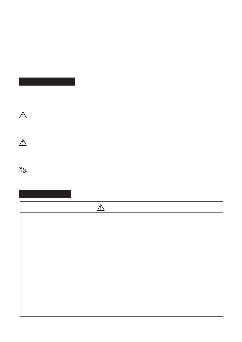
1 Unpacking
The illustration below shows the items included
for the standard specification printer .
Printer
Screws
For details, see page 7.
If any items are damaged, please contact your
dealer for assistance.
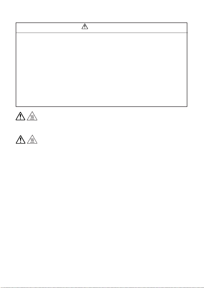
2 Machine Layout
Paper roll
Cable
Connects the printer to
the IM-300.
Printer cover
Cutter cover
Cover open button
4
Page 6
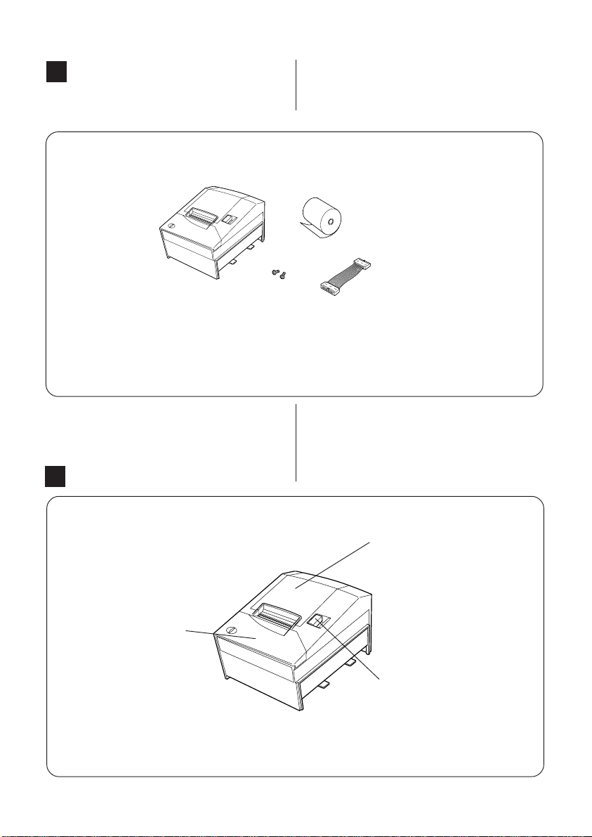
Labels
Paper-roll replacement guide label
Affixed to the inside of the print cover.
3 Confirming the DIP switches
Some application may require the alternation
of the DIP switches setting. Please confirm the
DIP switches setting before connecting the
printer. Please refer to P.14 for the DIP switches
setting.
Auto-cutter label
Affixed to the inside of the
cutter cover.
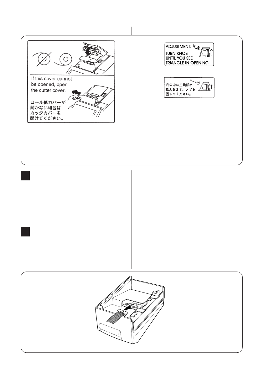
4 Connecting to the IM-300
Use the following procedure to connect the
printer to the IM-300.
1.Connect one end of the cable to connector
CN401 on the rear of the printer.
5
Page 7

2.Bend the cable as shonw below.
3.Remove the slot cover at the side of the IM-
300.
4.Connect the other end of the cable to the
connector on the IM-300.
5.Bend the cable as shown below.
6
Page 8

6. Slide the printer in the direction indicated
by the arrow so that the hooked area on the
printer fits into the groove on the base unit.
Make sure the cable isn't hooked at the projection of the plate.
7. Open the cover on the side of the printer,
and fasten the printer to the base unit using
the 2 screws included in the package.
8. Attach the slot cover to the IM-300.
7
Page 9

If necessary, you can remove the printer from
the IM-300 as follows.
1.Switch off the power on the base unit.
2. Remove the slot cover at the side of the IM-
300.
3.Remove the two screws holding the printer
to the IM-300.
4.Slide the printer to the left to remove it.
5. Disconnect the cable from the connector on
the IM-300.
5
Installing or Replacing the Paper Roll
Notes:
Be sure to use paper rolls that meet the
specifications.
Notes:
Do not use paper rolls that have the paper
glued to the core because the printer cannot detect the paper and correctly.
Installing
1.Make sure that the printer is not receiving
data; otherwise, data may be lost. Open the
paper roll cover by pressing the cover-open
button. If the cover-open button will not open
the cover, see page 12 in Troubleshooting.
8
Page 10

2.Insert the paper roll as shown.
Notes:
Be sure to note the correct direction that
the paper comes off the roll.
3.Pull out a small amount of paper, as shown.
4.Then close the cover.
9
Page 11

5.Tear off the paper as shown.
Replacing
1.Remove the used paper roll core.
6 Running a self-test
(printer operation check)
You can use the self-test feature to confirm that
the printer is operating correctly. Although it
is not strictly necessity to run this test, it is
generally a good idea to run it at least once to
check the operation. If the printer is not attached
to the IM-300, the self-test can't be executed.
The self-test checks the following.
・Control circuits
・Printer mechanism
・Print quality
・Control ROM version
・DIP-switch settings
Execution of Self-test
1.Turn off the IM-300.
10
Page 12

2. Confirm that the roll paper is set to the
printer.
3.Keep pressing the FEED button on the IM300 base unit.
4. Turn on the IM-300 to start the self-test.
5.Press the FEED button to continue printing.
The printer prints a pattern using the builtin character set.
Note:
If you want to pause the self test manually,
press the FEED button. Press the FEED
button again to continue the self test.
6. The self test automatically ends cuts the paper after
printing the following: ***completed***
The printer is ready to receive data as soon
as it completes the self test.
7 Paper jam
Cautions
Do not touch the print head because it can
be very hot after printing continuously for
a long time.
To clear a paper jam, follow the steps below:
1. Press the cover open button to open the
cover.
2.Remove the jammed paper and put the roll
back in the printer and close the cover.
11
Page 13

Note:
If paper is caught in the automatic cutter and
the printer cover cannot be opened, slide the
cutter cover as shown below.
If the auto cutter does not return to its normal
position by itself, follow the steps below to
correct the problem:
Slide the auto cutter cover as shown below so
that you can rotate the cutter motor knob.
Following the instructions on the label, rotate the knob until the ▽ appears in the hole.
Note:
If foreign object such as a push pin or paper clip drops in the auto cutter and causes
the auto cutter to lock up, the printer enters an error state and begins the recovery
operation automatically.
Note:
Do not open the auto cutter cover unless
the printer cover won't open.
12
Page 14

8 Setting the DIP Switches
TM-T88R
The functions of the switches are shown in the
following tables.
DIP Switch 1
SW Function ON OFF
Data receive error
1
Receive buffer capacity
2
3 Handshaking XON/XOFF DTR/DSR
4 Data word length 7 bits 8bits
5 Parity check Enabled Dsabled
6 Parity selection Even Odd
7 Transmission speed
8 (See the table below)
Transmission Speed
Transmission Speed
[BPS] 7 8
2400 ON ON
4800 OFF ON
9600 ON OFF
19200 OFF OFF
DIP Switch 2
SW Function ON OFF
1 Handshaking Receive Off line or
(BUSY condition)
2 Reserved do not change settings
Selects print density
3
4
5 Reserved do not change settings
6 Reserved do not change settings
I/F pin 12 reset signal
7
Unused
8
• lgnored Prints"?"
45 bytes 4K bytes
Switch No.
buffer full receive buffer
•iRefer to table below•j
Enabled Disabled
Unused
Print Density Selection
Print Density
Level
1 (Light) ON ON
2 OFF OFF
3 ON OFF
4 (Dark) OFF ON
Switch No.
34
13
Page 15

TM-T88IIR
The functions of the switches are shown in the
following tables.
DIP Switch 1
SW Function ON OFF
Data receive error
1
Receive buffer capacity
2
3 Handshaking XON/XOFF DTR/DSR
4 Data word length 7 bits 8bits
5 Parity check Enabled Dsabled
6 Parity selection Even Odd
7 Transmission speed
8 (See the table below)
lgnored Prints"?"
45 bytes 4K bytes
Transmission Speed
Transmission Speed
[BPS] 7 8
2400 ON ON
4800 OFF ON
9600 ON OFF
19200 OFF OFF
Switch No.
DIP Switch 2
SW Function ON OFF
1 Handshaking Receive Off line or
(BUSY condition)
2 Reserved Fixed to OFF.
Selects Print density
3
/Low power mode
4
5 Reserved Fixed to OFF
6 Reserved Fixed to OFF
I/F pin 12 reset signal
7
8 Unused Unused
buffer full receive buffer
(Refer to table below)
Enabled Disabled
Print Density Selection
Print Density
Level
1
Low power mode ON ON
2 OFF OFF
3 ON OFF
4 Dark OF F ON
Switch No.
3 4
Normal
14
Page 16

If you need to change settings, follow the steps
below to make your changes:
Caution
Turn off the IM-300 remove the printer from
it while changing the settings of the DIP
switches to prevent an electric short, which
can damage the printer.
1.Make sure the IM-300 is turned off.
2.Remove the printer from the IM-300. Please
refer to 4 for the removal procedure.
3.Remove the screw from the printer bottom
cover. Then take off the printer bottom cover,
as shown in the illustration below.
4. Set the switches using a pointed tool, such as
tweezers or a small screwdriver.
5.Replace the printer bottom cover. Then secure it with the screw.
Note:
The new settings take effect when you turn
on the IM-300.
15
Page 17

9 Adjusting the Remaining-
Paper Detector
Read this section only if you are using the remaining-paper detection feature.
Note
Rolls should be of specified paper type, and should
have an inner diameter (core diameter) of 12mm
and an outer diameter of 18mm.
1.Open the cover of the paper-roll area, and
remove the current paper roll.
2. Loosen the adjustment screw holding the de-
tector in place, and align the top of the positioning plate to the adjustment scale.
Approximate remaining paper level for each
scale setting is as follows.
#1 23mm
#2 27mm
3.Tighten the adjustment screw.
4. Confirm that the detection lever moves
smoothly.
5.Load a paper roll.
16
Page 18

17
Printed in Japan
1999.12
 Loading...