

Page 1
Technical Reference Guide
Describes features of the product.
Describes setup and instrallation of the product and
peripherals.
Describes the modes to set and check settings.
Describes how to control the printer and necessary
information when you develop applications.
Describes how to handle the product.
Describes precautions for replacement.
Describes general specications and character codes.
Product Overview
Setup
Setting/Checking Modes
Application Development Information
Handling
Replacement of the TM-T70
Appendix
M00063503
Rev.D
Page 2

Cautions
• No part of this document may be reproduced, stored in a retrieval system, or transmitted in any form or by any means,
electronic, mechanical, photocopying, recording, or otherwise, without the prior written permission of Seiko Epson Corpo-
ration.
• The contents of this document are subject to change without notice. Please contact us for the latest information.
• While every precaution has been taken in the preparation of this document, Seiko Epson Corporation assumes no respon-
sibility for errors or omissions.
• Neither is any liability assumed for damages resulting from the use of the information contained herein.
• Neither Seiko Epson Corporation nor its affiliates shall be liable to the purchaser of this product or third parties for
damages, losses, costs, or expenses incurred by the purchaser or third parties as a result of: accident, misuse, or abuse of
this product or unauthorized modifications, repairs, or alterations to this product, or (excluding the U.S.) failure to strictly
comply with Seiko Epson Corporation’s operating and maintenance instructions.
• Seiko Epson Corporation shall not be liable against any damages or problems arising from the use of any options or any
consumable products other than those designated as Original Epson Products or Epson Approved Products by Seiko
Epson Corporation.
Trademarks
EPSON is a registered trademark of Seiko Epson Corporation.
Exceed Your Vision and ESC/POS are registered trademarks or trademarks of Seiko Epson Corporation.
Microsoft and Windows are registered trademarks of Microsoft Corporation.
®
The Bluetooth
Seiko Epson Corporation is under license.
IOS is a trademark or registered trademark of Cisco in the U.S. and other countries and is used under license.
All other trademarks are the property of their respective owners and used for identification purpose only.
word mark and logos are registered trademarks owned by Bluetooth SIG, Inc. and any use of such marks by
ESC/POS® Command System
Epson ESC/POS is a proprietary POS printer command system that includes patented or patent-pending commands. ESC/POS
is compatible with most Epson POS printers and displays.
ESC/POS is designed to reduce the processing load on the host computer in POS environments. It comprises a set of highly
functional and efficient commands and also offers the flexibility to easily make future upgrades.
© Seiko Epson Corporation 2013-2018. All rights reserved.
2
Page 3
For Safety
Key to Symbols
The symbols in this manual are identified by their level of importance, as defined below. Read the following
carefully before handling the product.
You must follow warnings carefully to avoid serious bodily injury.
WARNING
Provides information that must be observed to prevent damage to the equipment or loss of data.
• Possibility of sustaining physical injuries.
CAUTION
• Possibility of causing physical damage.
• Possibility of causing information loss.
Provides information that must be observed to avoid damage to your equipment or a
malfunction.
Provides important information and useful tips.
3
Page 4
Warnings
WARNING
• To avoid risk of electric shock, do not set up this product or handle cables during a
thunderstorm.
• Never insert or disconnect the power plug with wet hands.
Doing so may result in severe shock.
• Handle the power cable with care.
Improper handling may lead to fire or electric shock.
∗ Do not modify or attempt to repair the cable.
∗ Do not place any heavy object on top of the cable.
∗ Avoid excessive bending, twisting, and pulling.
∗ Do not place the cable near heating equipment.
∗ Check that the plug is clean before plugging it in.
∗ Be sure to push the plug all the way in.
• Be sure to use the specified power source.
Connection to an improper power source may cause fire or shock.
• Do not place multiple loads on the power outlet.
Overloading the outlet may lead to fire.
• Shut down your equipment immediately if it produces smoke, a strange odor, or unusual
noise.
Continued use may lead to fire. Immediately unplug the equipment and contact qualified
service personnel.
• Never attempt to repair this product yourself.
Improper repair work can be dangerous.
• Never disassemble or modify this product.
Tampering with this product may result in injury or fire.
• Do not allow foreign matter to fall into the equipment.
Penetration by foreign objects may lead to fire.
• If water or other liquid spills into this equipment, do not continue to use it.
Continued use may lead to fire. Unplug the power cord immediately and contact qualified
service personnel.
• Do not use aerosol sprayers containing flammable gas inside or around this product.
Doing so may cause fire.
Cautions
• Do not connect cables in ways other than those mentioned in this manual.
Different connections may cause equipment damage or fire.
CAUTION
• Be sure to set this equipment on a firm, stable, horizontal surface.
The product may break or cause injury if it falls.
• Do not use this product in locations subject to high humidity or dust levels.
Excessive humidity and dust may cause equipment damage or fire.
• Do not place heavy objects on top of this product. Never stand or lean on this product.
Equipment may fall or collapse, causing breakage and possible injury.
• To avoid injury, do not insert fingers or any part of the hand in the roll paper opening
where the manual cutter is installed.
• Do not open the roll paper cover without taking the necessary precautions, as this can
result in injury from the autocutter fixed blade.
• To ensure safety, unplug this product before leaving it unused for an extended period.
4
Page 5

Restriction of Use
When this product is used for applications requiring high reliability/safety, such as transportation devices
related to aviation, rail, marine, automotive, etc.; disaster prevention devices; various safety devices, etc.; or
functional/precision devices, etc., you should use this product only after giving consideration to including fail-
safes and redundancies into your design to maintain safety and total system reliability. Because this product was
not intended for use in applications requiring extremely high reliability/safety, such as aerospace equipment,
main communication equipment, nuclear power control equipment, or medical equipment related to direct
medical care, etc., please make your own judgment on this product’s suitability after a full evaluation.
5
Page 6

About this Manual
Aim of the Manual
This manual was created to provide information on development, design, and installation of POS systems and
development and design of printer applications for developers.
Manual Content
The manual is made up of the following sections:
Chapter 1
Chapter 2
Chapter 3
Chapter 4
Chapter 5
Chapter 6
Appendix
Product Overview
Setup
Setting/Checking Modes
Application Development Information
Handling
Replacement of the TM-T70
Product Specifications
Option Specifications
Specifications of Interface and Connector
Character Code Tables
6
Page 7

Contents
■ For Safety..........................................................................................................................................3
Key to Symbols.......................................................................................................................................................................................... 3
Warnings...................................................................................................................................................................................................... 4
Cautions....................................................................................................................................................................................................... 4
■ Restriction of Use.............................................................................................................................5
■ About this Manual ...........................................................................................................................6
Aim of the Manual ................................................................................................................................................................................... 6
Manual Content........................................................................................................................................................................................ 6
■ Contents............................................................................................................................................7
Product Overview ............................................................................... 11
■ Features..........................................................................................................................................11
■ Product Configuration...................................................................................................................12
Interface..................................................................................................................................................................................................... 12
Buzzer ......................................................................................................................................................................................................... 12
Color............................................................................................................................................................................................................12
Accessories ...............................................................................................................................................................................................12
■ Parts Name and Function..............................................................................................................14
Power Switch ........................................................................................................................................................................................... 14
Power Switch Cover...............................................................................................................................................................................14
Control Panel ...........................................................................................................................................................................................15
Connectors ...............................................................................................................................................................................................16
Offline.........................................................................................................................................................................................................16
■ Error Status.....................................................................................................................................17
Automatically Recoverable Errors....................................................................................................................................................17
Recoverable Errors.................................................................................................................................................................................17
Unrecoverable Errors ............................................................................................................................................................................18
■ NV Memory (Non-Volatile Memory).............................................................................................19
NV Graphics Memory............................................................................................................................................................................19
User NV Memory.....................................................................................................................................................................................19
Memory Switches................................................................................................................................................................................... 19
R/E (Receipt Enhancement)................................................................................................................................................................20
User-defined Page .................................................................................................................................................................................20
Maintenance Counter........................................................................................................................................................................... 20
7
Page 8

Setup .................................................................................................... 21
■ Flow of Setup................................................................................................................................. 21
■ Installing the Printer..................................................................................................................... 22
Important Notes on Installation....................................................................................................................................................... 23
Affixing Position of DF-10................................................................................................................................................................... 23
■ Connecting the Printer to the Host Computer............................................................................ 24
For Serial Interface ................................................................................................................................................................................ 24
For Parallel Interface............................................................................................................................................................................. 26
For USB Interface ................................................................................................................................................................................... 27
For LAN Interface ................................................................................................................................................................................... 29
For Wireless LAN Interface .................................................................................................................................................................. 30
For Bluetooth Interfaces...................................................................................................................................................................... 30
■ Connecting the AC Adapter.......................................................................................................... 31
Connecting the AC Adapter............................................................................................................................................................... 31
■ Setting the Memory Switches/Receipt Enhancement................................................................ 32
Functions.................................................................................................................................................................................................. 33
■ Connecting the Optional External Buzzer................................................................................... 42
Unpacking................................................................................................................................................................................................ 42
Installation Position .............................................................................................................................................................................. 42
Installation Procedures........................................................................................................................................................................ 43
Adjusting the Buzzer Volume............................................................................................................................................................ 44
Setting the Optional External Buzzer ............................................................................................................................................. 44
■ Connecting the Cash Drawer........................................................................................................ 45
Connecting the Drawer Kick-out Cable......................................................................................................................................... 45
Setting the Internal Buzzer (for Models with an Internal Buzzer) ........................................................................................ 46
Setting/Checking Modes .................................................................... 47
Self-test Mode......................................................................................................................................................................................... 47
Hexadecimal Dumping Mode........................................................................................................................................................... 49
NV Graphics Information Print Mode ............................................................................................................................................. 50
R/E (Receipt Enhancement) Information Print Mode ............................................................................................................... 51
Memory Switch Setting Mode .......................................................................................................................................................... 52
Application Development Information ............................................. 59
■ Controlling the Printer.................................................................................................................. 59
ESC/POS .................................................................................................................................................................................................... 59
■ Controlling the Cash Drawer........................................................................................................ 60
■ Controlling the Built-in Buzzer .................................................................................................... 61
■ Controlling the Optional External Buzzer................................................................................... 62
■ Software and Manuals .................................................................................................................. 63
Development Kits.................................................................................................................................................................................. 63
Drivers........................................................................................................................................................................................................ 64
8
Page 9

Utilities........................................................................................................................................................................................................65
Download..................................................................................................................................................................................................66
Handling .............................................................................................. 67
■ Installing and Replacing Roll Paper .............................................................................................67
■ Removing Jammed Paper .............................................................................................................69
■ Cleaning the Thermal Head ..........................................................................................................69
■ Preparing for Transport.................................................................................................................70
Replacement of the TM-T70................................................................ 71
■ Compatibility .................................................................................................................................71
Printing.......................................................................................................................................................................................................71
Print Density.............................................................................................................................................................................................71
Number of Head Energizing Parts....................................................................................................................................................71
Printable Area (for 80 mm Width Paper/58 mm Width Paper) ...............................................................................................71
Cutting Method.......................................................................................................................................................................................72
Manual Paper Feed ................................................................................................................................................................................72
Receive Buffer ..........................................................................................................................................................................................72
Memory Capacity ...................................................................................................................................................................................72
Electrical Characteristics ......................................................................................................................................................................72
DIP Switches.............................................................................................................................................................................................72
Printer Status............................................................................................................................................................................................72
Logo Registration ...................................................................................................................................................................................73
Driver Compatibility ..............................................................................................................................................................................73
USB Power-Saving Function ...............................................................................................................................................................73
Maintenance Counter ...........................................................................................................................................................................73
Buzzer .........................................................................................................................................................................................................73
Overall Dimensions................................................................................................................................................................................74
■ Additional Functions and Functional Improvements.................................................................75
Print Speed................................................................................................................................................................................................75
Barcodes ....................................................................................................................................................................................................75
Number of Characters...........................................................................................................................................................................76
Image Tone Setting................................................................................................................................................................................76
Interface.....................................................................................................................................................................................................76
USB Class....................................................................................................................................................................................................76
Coupon Printing......................................................................................................................................................................................76
Memory Switches...................................................................................................................................................................................77
R/E Information Print Mode................................................................................................................................................................77
Reliability ...................................................................................................................................................................................................78
Appendix.............................................................................................. 79
■ Product Specifications ..................................................................................................................79
Printing Specifications..........................................................................................................................................................................80
Character Specifications ......................................................................................................................................................................82
Printable Area ..........................................................................................................................................................................................86
9
Page 10

Printing and Cutting Positions.......................................................................................................................................................... 88
Paper Specifications.............................................................................................................................................................................. 88
Electrical Characteristics ..................................................................................................................................................................... 90
Environmental Conditions ................................................................................................................................................................. 91
External Dimensions and Mass......................................................................................................................................................... 92
■ Option Specifications ................................................................................................................... 93
AC Adapter (PS-180)............................................................................................................................................................................. 93
■ Specifications of Interface and Connector.................................................................................. 94
RS-232 Serial Interface ......................................................................................................................................................................... 94
IEEE 1284 Parallel Interface ................................................................................................................................................................ 97
USB (Universal Serial Bus) Interface ..............................................................................................................................................100
■ Character Code Tables ................................................................................................................ 101
10
Page 11

Chapter 1 Product Overview
Product Overview
This chapter describes features and specifications of the product.
Features
The TM-T70II is a receipt printer with high speed printing and a small footprint. With its compact design, it
can be placed in a narrow space, such as under a counter, and it also has full front access for easy operability.
High speed printing
• Issuing of batch receipts is possible.
Maximum print speed: 250 mm/s {9.84
• Graphics are also printed with high-speed printing.
•Multi-tone graphic printing
• Coupon print function is supported.
"/s} (200 mm/s {7.87"/s} for some models)
Front operation
•Easy drop-in paper loading
• Front access operation of the power switch and operation panel
• Front access operation for receipt ejection
Software
• Command protocol is based on the ESC/POS Proprietary Command System.
• OPOS ADK and Windows printer driver are available.
• In addition to supporting several kinds of bar code printing, GS1-DataBar printing and two-dimensional
symbol (PDF417, QR code, MaxiCode, Composite Symbology) printing are possible.
1
• Various layouts are possible by using page mode.
• A maintenance counter function is supported.
• Paper-saving function is supported.
Environmental
• TM-T70II is ENERGY STAR qualified. (Some models may be exempted.)
Others
• Various interface boards (EPSON UB series) can be used.
• The TM-T70II Software & Documents Disc (drivers, utility software, and manuals)
11
Page 12
Product Configuration
Interface
• Serial interface model (RS-232)
• Parallel interface model (IEEE1284)
• USB interface model (full-speed)
• Ethernet interface model (100BASE-TX/10BASE-T)
• Wireless LAN interface model (IEEE802.11a/b/g/n)
• Bluetooth interface model (Bluetooth Ver.2.1 + EDR)
For this printer, never use a LAN interface board or a wireless LAN interface board with a
buzzer function.
CAUTION
Buzzer
Otherwise, the printer or the interface board may be damaged.
The name of interface boards with a buzzer function has “A” at the end.
Example) UB-E**A, UB-R**A (*: alphanumeric character)
• Model with the buzzer function
• Model without the buzzer function
The optional external buzzer and the internal buzzer cannot be used together at the same time.
Color
• ECW (Epson Cool White)
•EDG (Epson Dark Gray)
Accessories
Included
• Roll paper (for operation check)
•Power switch cover
•AC adapter*
• AC cable*
12
Page 13

•Locking wire saddle*
• The TM-T70II Software & Documents Disc (drivers, utility software, and manuals)*
•Setup Guide
• Warranty certificate*
* May not be included depending on the model.
Options
•AC adapter
•AC cable
• Connector cover (Model: OT-CC702W/OT-CC702B)
Protects cables and interface connected to the printer.
• Affixing tapes for fixing the printer (Model: DF-10)
• Interface boards (UB series)
• Optional external buzzer (Model: OT-BZ20)
Chapter 1 Product Overview
1
13
Page 14
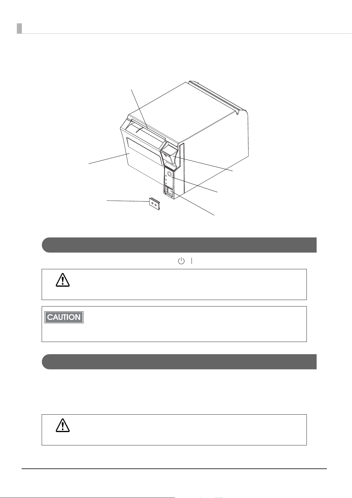
Parts Name and Function
Manual cutter
Roll paper cover
Power switch cover
Cover open lever
Control panel
Power switch
Power Switch
Turns the printer on or off. The marks on the switch: ( / )
Before turning on the printer, be sure to check that the AC adapter is connected to the
power supply.
CAUTION
Before turning the printer off, it is recommended to send a power-off command to the printer. If
you use the power-off sequence, the latest maintenance counter values are saved. (Maintenance
counter values are usually saved every two minutes.)
For detailed information about ESC/POS commands, see the ESC/POS Command Reference.
Power Switch Cover
Install the power switch cover that comes with the TM-T70II onto the printer to prevent inadvertent changing
of the power switch, to prevent tampering, and to improve the appearance of the printer.
To reset the printer when the power switch cover is installed, insert a long, thin object (such as the end of a
paper clip) into the hole in the power switch cover and press the power switch.
WARNING
14
If an accident occurs with the power switch cover attached, unplug the power cord
immediately.
Continued use may cause fire or shock.
Page 15
Chapter 1 Product Overview
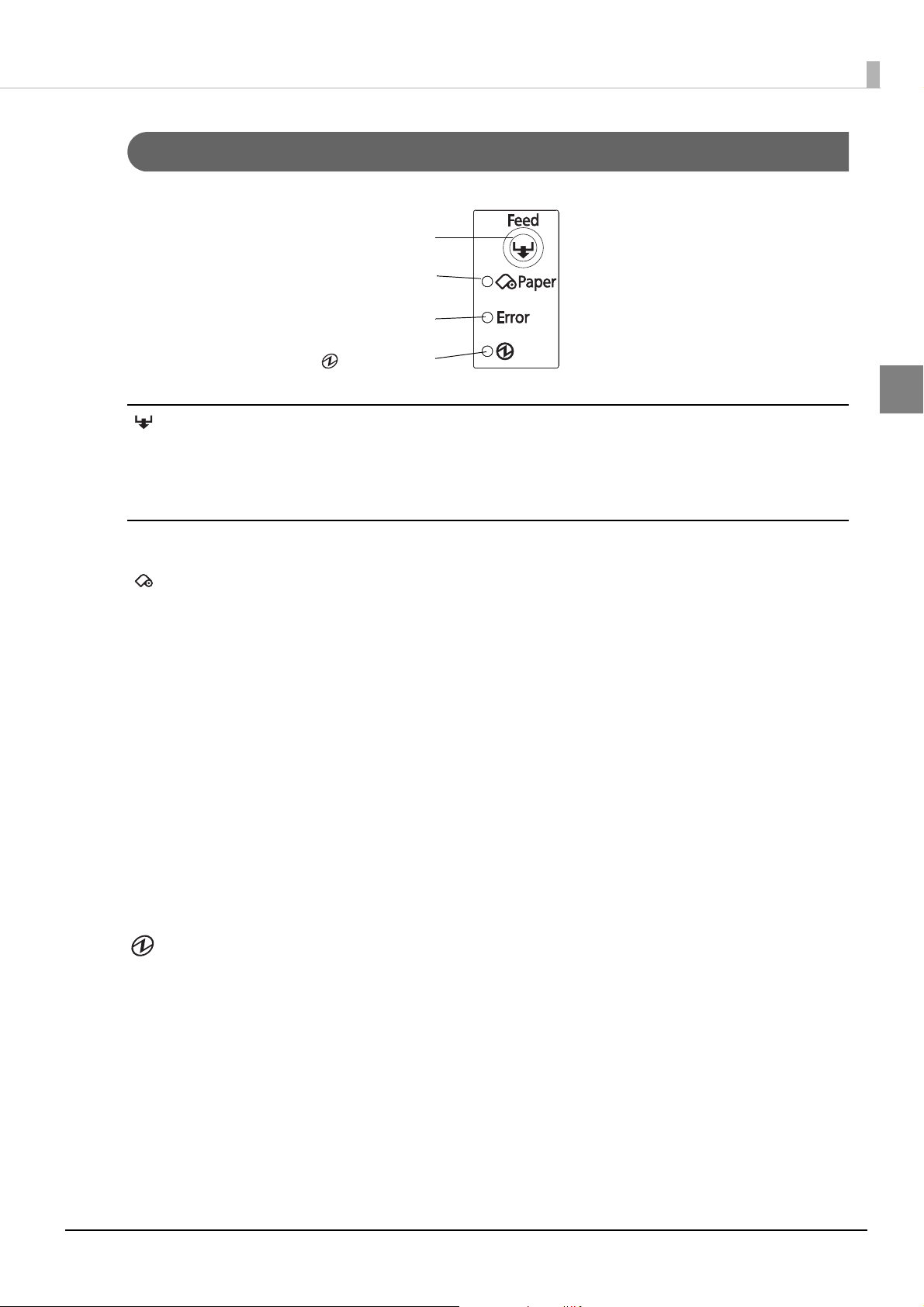
(Power) LED
Feed button
Paper LED
Error LED
Control Panel
Feed button
Pressing this button once feeds the roll paper by one line. Holding this button down feeds the roll paper
continuously.
1
LEDs
Paper LED (orange)
• Lights when there is little remaining.
• Off when there is a sufficient amount of roll paper remaining.
• Flashes when a self-test is in progress or when macro execution standby state.
Error LED (orange)
Lights or flashes when the printer is offline.
• Lights after the power is turned on or after a reset (offline). Automatically goes out after a while to indicate
that the printer is ready.
• Lights when the end of the roll paper is detected, and when printing has stopped (offline). If this happens,
replace the roll paper.
• Flashes when an error occurs. (For details about the flash codes, see "Error Status" on page 17.)
Goes out during regular operation (online).
•
POWER LED (green)
• Lights when the power supply is on.
• Goes out when the power supply is turned off.
15
Page 16
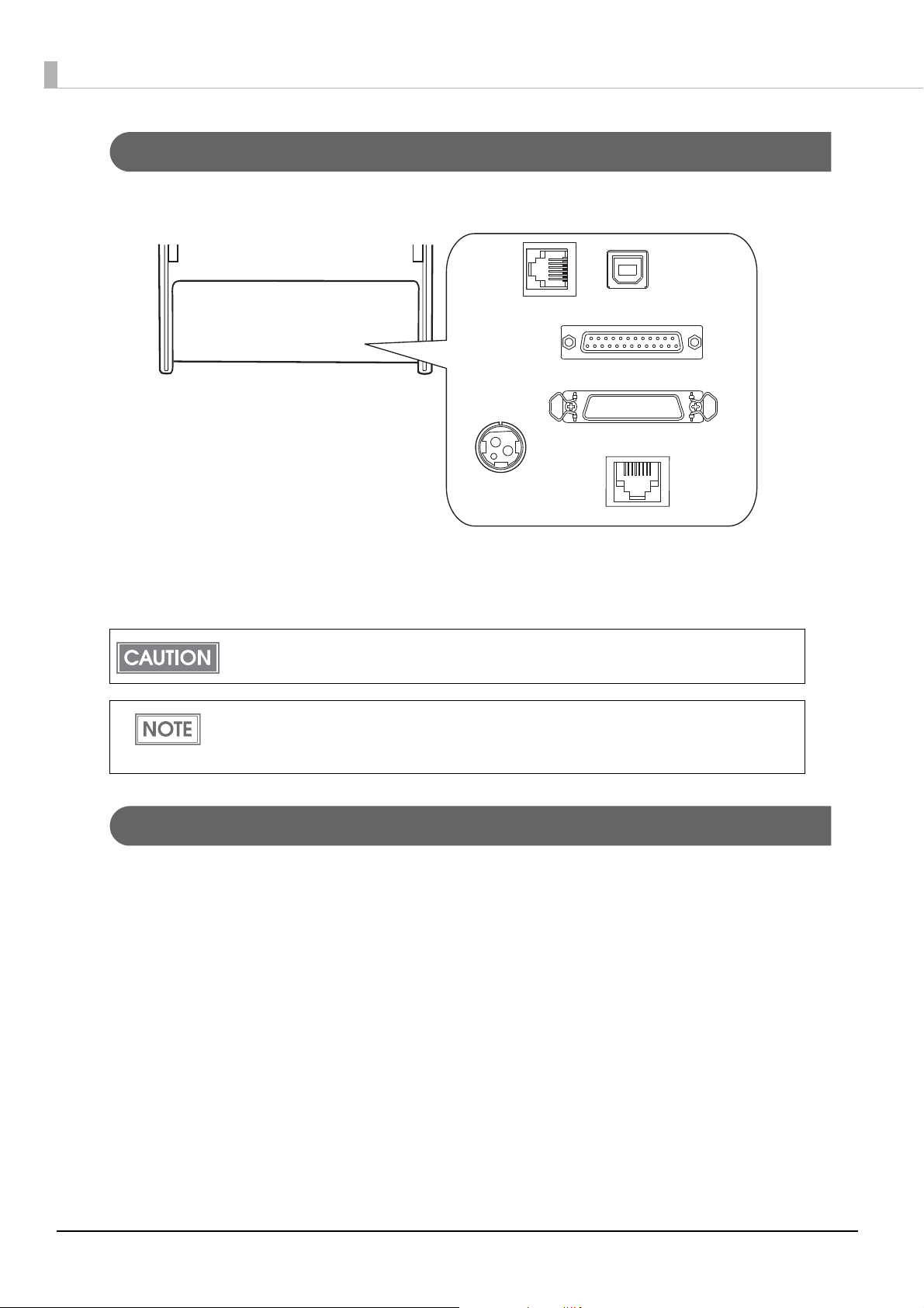
Connectors
USB interface
Power supply
connector
Drawer kick
connector
LAN interface
Serial interface
Parallel interface
All cables are connected to the connector panel on the lower rear of the printer.
• Drawer kick connector: Connects the cash drawer or the optional external buzzer.
• Power supply connector: Connects the AC adapter.
• Interface connector: Connects the printer with the host computer interface.
For printers on which the standard USB connector has a cap, you cannot use the standard USB
interface.
For details on the various interfaces and how to connect the power supply connector and cash
drawer, see "Connecting the Printer to the Host Computer" on page 24 and "Connecting the Cash
Drawer" on page 45.
Offline
The printer automatically goes offline under the following conditions:
• During power on (including resetting with the interface) until the printer is ready
• During the self-test
• When the roll paper cover is open
• While roll paper is fed using the Feed button
• When the printer stops printing due to a paper-end (if an empty paper supply is detected by the roll paper
end sensor or if the driver has been set to stop printing when a roll paper near-end is detected)
• During a macro execution standby state
•When an error has occurred
16
Page 17
Chapter 1 Product Overview
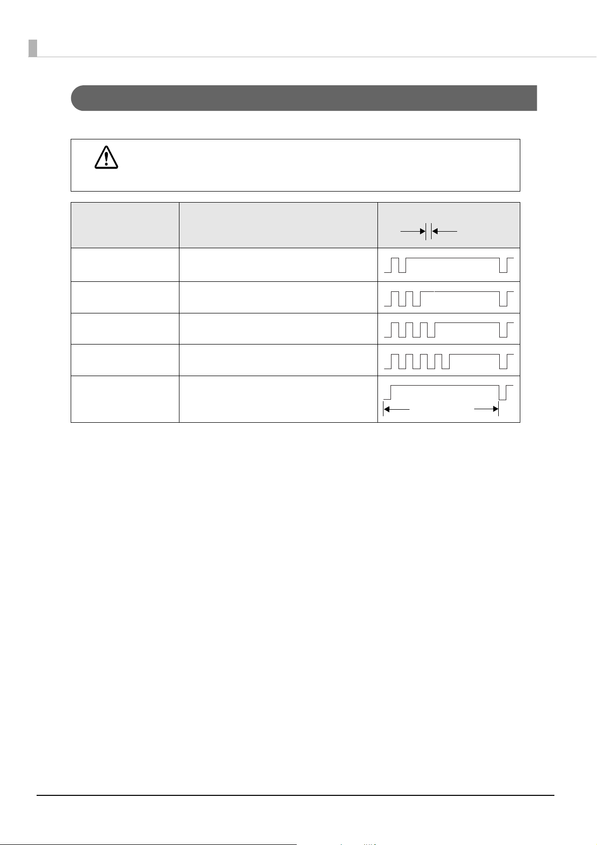
Approx.
160 ms
Approx.
160 ms
Approx.2.56 s
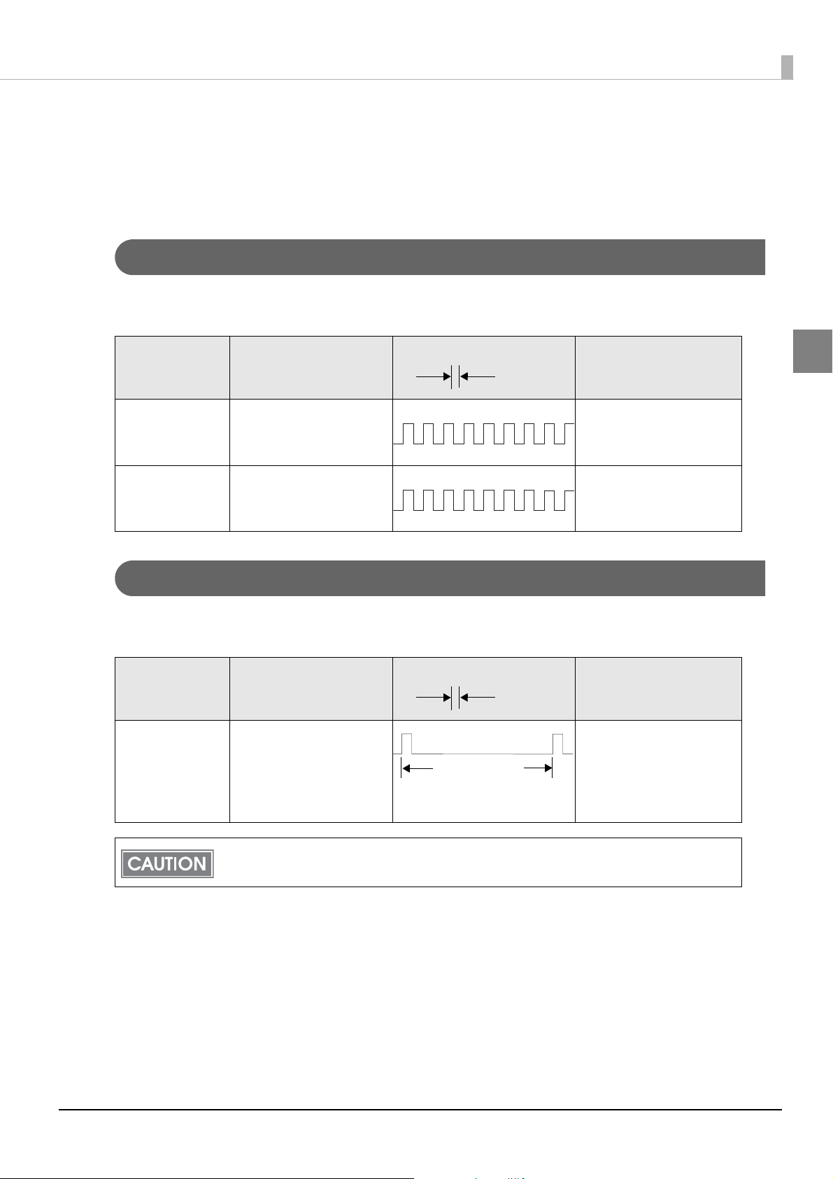
Error Status
There are three possible error types: automatically recoverable errors, recoverable errors, and unrecoverable
errors.
Automatically Recoverable Errors
Printing is no longer possible when automatically recoverable errors occur. They can be recovered easily, as
described below.
Error LED flash code
Error Error description
Roll paper cover
open error
Print head
temperature error
The roll paper cover was
opened during printing.
A high temperature outside
the head drive operating
range was detected.
Recovery measure
Recovers automatically
when the roll paper cover is
closed.
Recovers automatically
when the print head cools.
Recoverable Errors
Printing is no longer possible when recoverable errors occur. They can be recovered easily by sending an error
recovery command after eliminating the cause of the error.
Error LED flash code
Error Error description
Autocutter error Autocutter does not work
correctly.
Recovery measure
Remove the jammed paper
or foreign matter in the
printer, close the roll paper
cover, send the error recover
command.
1
The error recovery command is valid only if a recoverable error (excluding automatically
recoverable errors) occurs.
17
Page 18
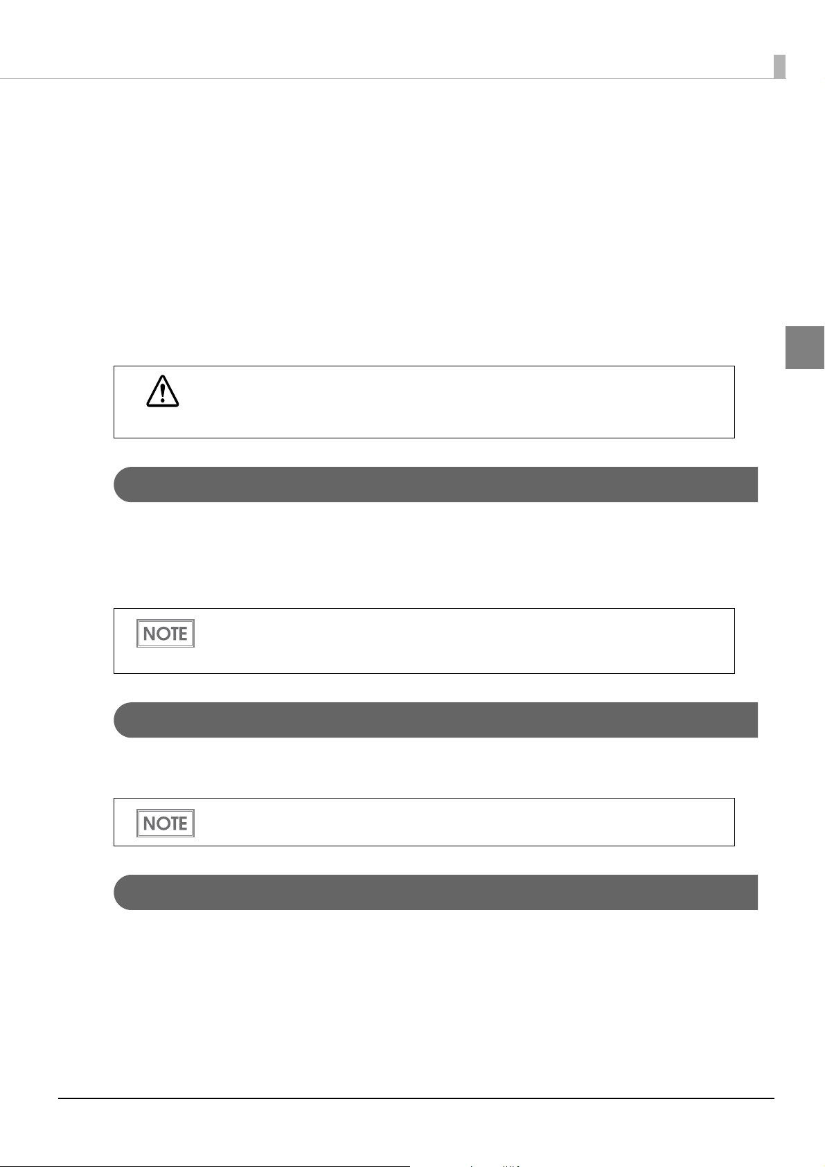
Unrecoverable Errors
Approx.
160 ms
Approx.2.56 s
Printing is no longer possible when unrecoverable errors occur. The printer must be repaired.
Turn off the power immediately when unrecoverable errors occur.
CAUTION
Error LED flash code
Error Error description
Memory R/W error After R/W checking, the printer does not work
correctly.
High voltage error The power supply voltage is extremely high.
Low voltage error The power supply voltage is extremely low.
CPU execution error The CPU is executing an incorrect address.
Internal circuit
connection error
Internal circuits are not connected correctly.
18
Page 19
Chapter 1 Product Overview
NV Memory (Non-Volatile Memory)
The printer's NV memory stores data even after the printer power is turned off. NV memory contains the
following memory areas for the user:
• NV graphics memory
• User NV memory
•Memory switches
• R/E (Receipt Enhancement)
•User-defined page
• Maintenance counter
As a guide, NV memory rewriting should be 10 times or less a day when you program
applications.
CAUTION
NV Graphics Memory
Graphics, such as shop logos to be printed on receipts, can be stored. Even with a serial interface model whose
communication speed is low, high speed graphics printing is possible.
Use the TM-T70II Utility to register graphics. You can also use the TM-T70II Utility or the NV graphics
information print mode to confirm the registered graphics.
• For detailed information about the TM-T70II Utility, see the TM-T70II Utility User’s Manual.
• For information about how to use the NV graphics information print mode, see "NV Graphics
nformation Print Mode" on page 50.
I
User NV Memory
1
You can store and read text data for multiple purposes, such as for storing a note including customizing or
maintenance information of the printer. Use ESC/POS commands to store and read the text data.
or information about ESC/POS commands, see the ESC/POS Command Reference.
F
Memory Switches
With the memory switches, which are software switches for the printer, you can configure various settings of the
printer. For information about the memory switches, see "S
on page 32.
etting the Memory Switches/Receipt Enhancement"
19
Page 20
R/E (Receipt Enhancement)
Graphics, such as shop logos to be printed on top or bottom of receipts can be registered.
For information about R/E, see "Setting the Memory Switches/Receipt Enhancement" on page 32.
User-defined Page
You can store character data in the user-defined page (character code table: page 255) so that you can also print
characters not resident in the printer.
• For the character code table, see "Character Code Tables" on page 101.
• User-defined page is not supported by South Asia font models.
Maintenance Counter
With this function, printer information, such as the number of lines printed, the number of autocuts, and
printer operation time after the printer starts working, is automatically stored in NV memory. You can read the
information with the Status API of the APD or OPOS ADK to use it for periodical checks or part replacement.
Maintenance Counter can be checked with the TM-T70II Utility or in a self-test.
20
Page 21
Setup
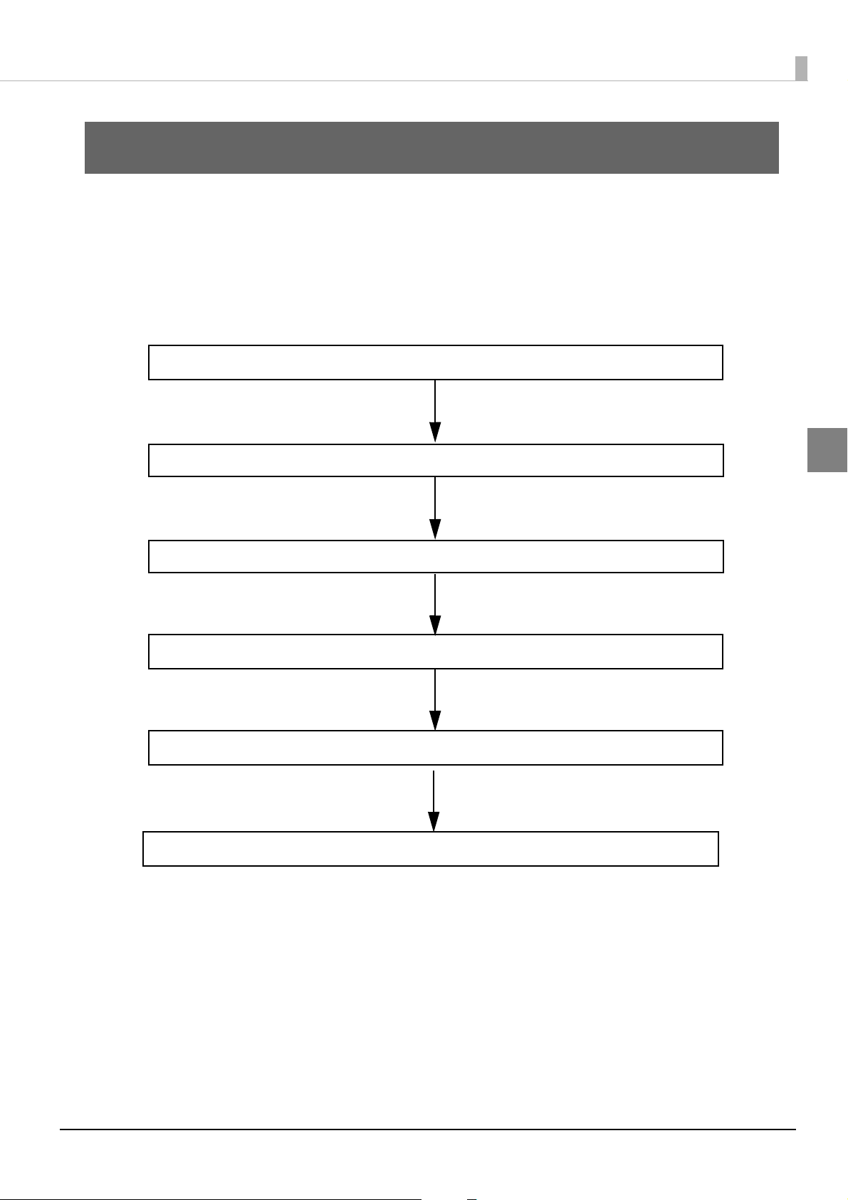
1. Installing the Printer (page 22)
5. Connecting the Optional External Buzzer (page 42)
4. Setting the Memory Switches/Receipt Enhancement (page 32)
3. Connecting the AC Adapter (page 31)
6. Connecting the Cash Drawer (page 45)
2. Connecting the Printer to the Host Computer (page 24)
This chapter describes setup and installation of the product and peripherals.
Flow of Setup
This chapter consists of the following sections along with the setup flow of the product and peripherals.
Chapter 2 Setup
2
21
Page 22
Installing the Printer
Within
± 3°
Within
± 3°
Horizontal
Range that manual cutting is possible
Area required for loading the roll paper
(diameter: 83 mm)
60° or more
137 mm
109.5 mm
7.5 mm
Shelf height: 150 mm
Shelf height: 140 mm
Shelf height: 127 mm
Manual cutter
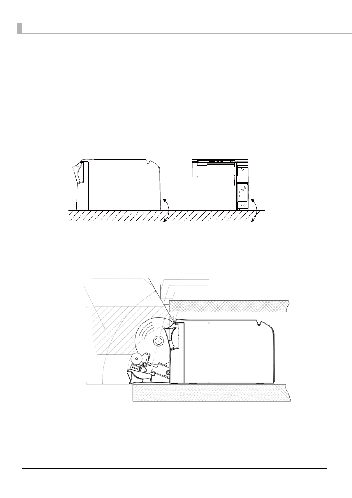
You can install this printer only horizontally.
Fix the printer so that it does not move around when you open the roll paper cover and cut roll paper. A tape for
fixing the printer is available as an option. (See "Affixing Position of DF-10" on page 23.)
s shown in the figure below, install the printer with a maximum tilt of 3°.
A
Installing the printer with a tilt of more than 3° may cause the following problems.
• Roll paper near end cannot be detected.
• The roll paper cover will not close after installing roll paper.
• Roll paper cannot be taken out.
If the printer installation does not fit within the specifications shown in the figure below, the following
problems may occur.
• Cannot set the roll paper in the printer
• Cannot cut the paper with the manual cutter
22
Page 23
Chapter 2 Setup
118.5
Affixing position of the DF-10
Important Notes on Installation
• The printer must be installed horizontally.
• Do not place the printer in dusty locations.
• Do not catch cables or foreign matter under the printer.
• Do not put anything that has a force of more than 32.7 N {3 kgf} on the top of the printer.
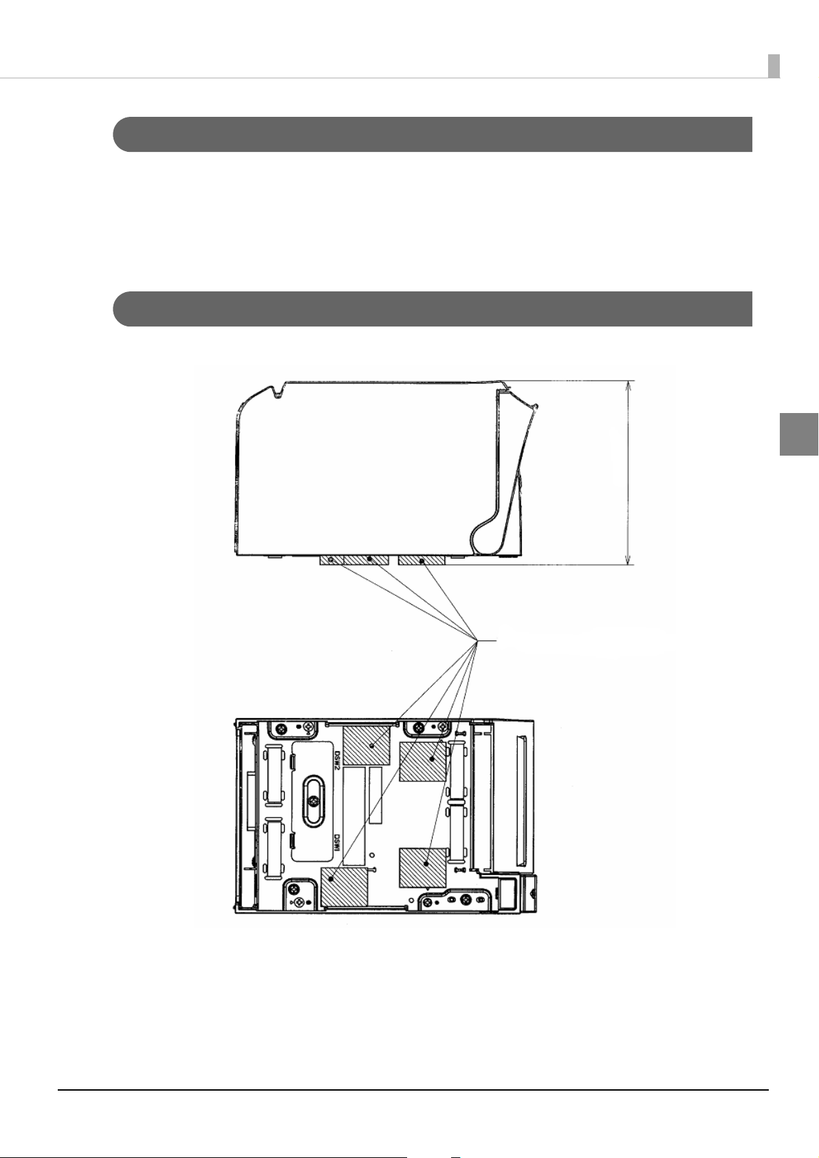
Affixing Position of DF-10
When you use the affixing tapes for fixing the printer (Model: DF-10), paste them as shown in the figure below.
2
23
Page 24
Connecting the Printer to the Host Computer
TM-T70II
Serial cable
DM-D
(Serial I/F model)
Extension cable for
power supply
Serial cable
Modular cable
Cash drawer
AC adapter + AC cable
DM-D
(USB I/F model)
Serial cable
Modular cable
Cash drawer
AC adapter + AC cable
TM-T70II
USB cable
• Be sure to install the printer driver before connecting the printer to the host computer.
• The printer uses a modular connector specifically designed for the cash drawer. Do not
connect the connector to an ordinary telephone line.
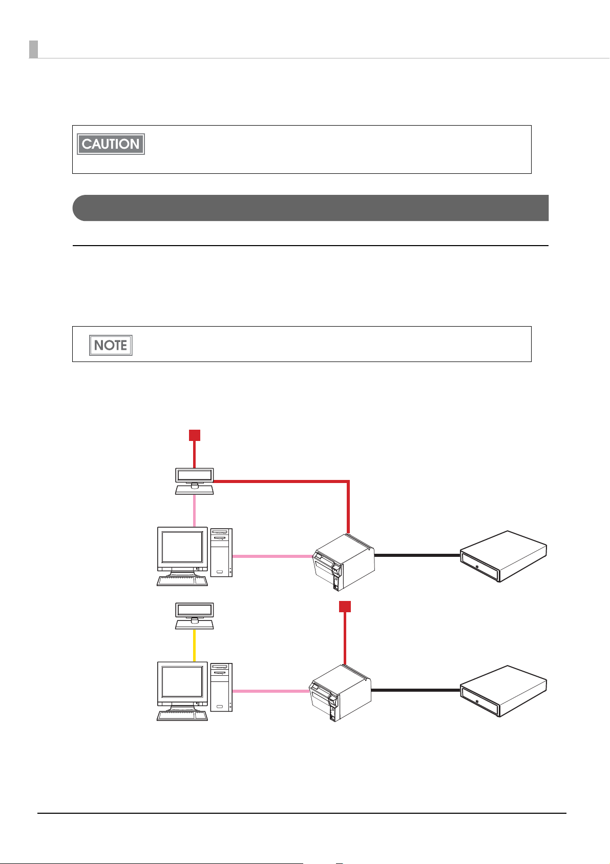
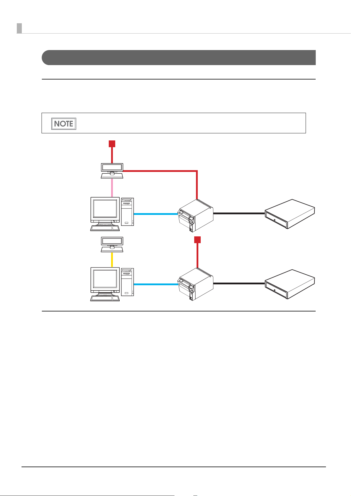
For Serial Interface
Serial interface connection diagram
When this printer is connected to a host computer by the serial interface, two connection forms are possible:
•Stand alone
• Y connection
• The modular cable is mounted on the cash drawer.
• Use the extension cable for power supply bundled with the customer display.
Stand alone
This printer is connected to the host computer via the serial port. When a customer display (DM-D) is to be
connected, connect it to the host computer via the serial port or USB port.
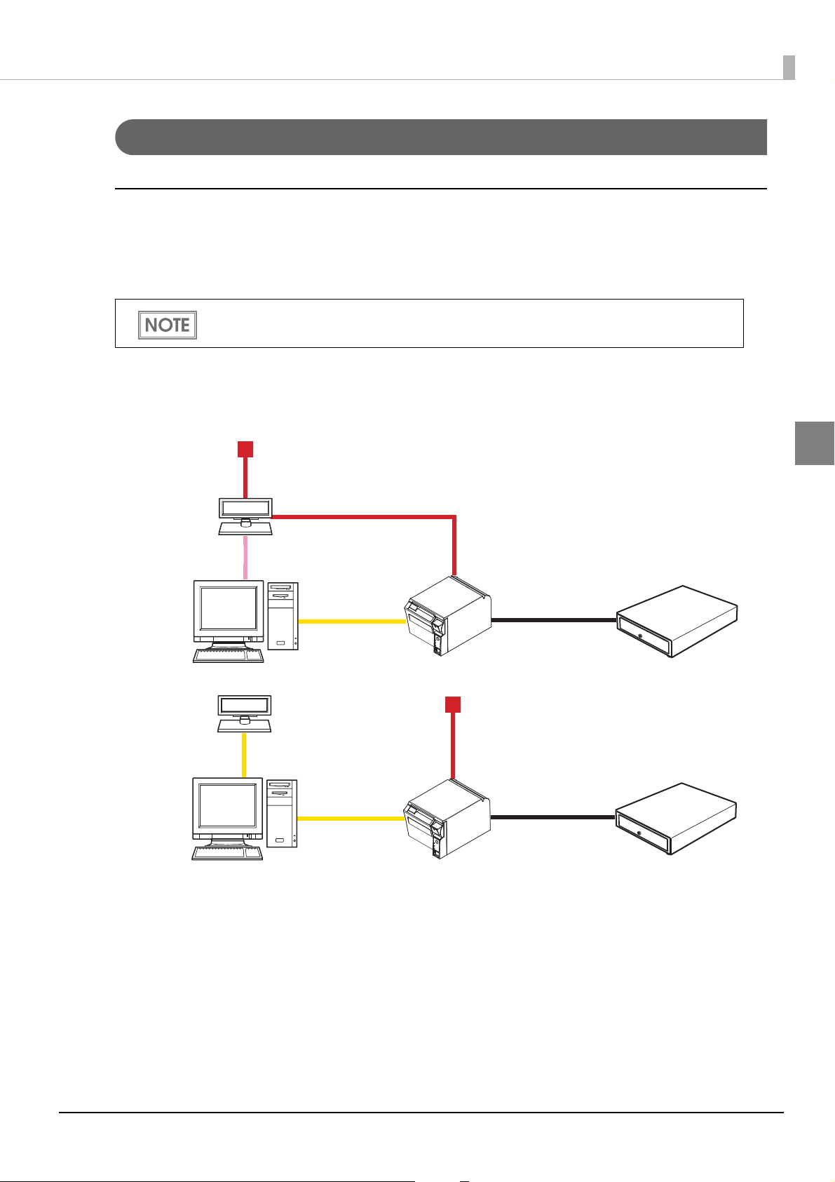
Y connection (only for models with a customer display (DM-D) connector)
This printer is connected to the host computer via the serial port. When a customer display (DM-D) is to be
connected, connect it to the printer via the modular cable.
24
Page 25
Chapter 2 Setup
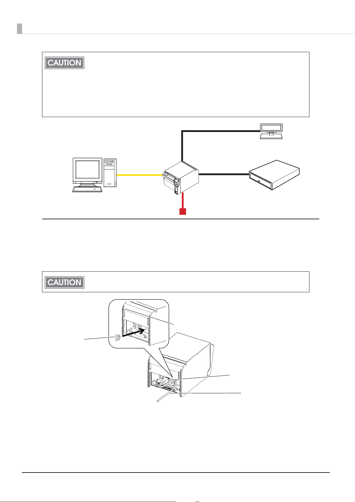
Modular cable
Modular cable
DM-D
Cash drawer
TM-T70II
Serial cable
AC adapter + AC cable
• Make sure to pull out the power cable before connecting cables.
• When connecting a customer display to the printer, connect the modular jack from the
customer display to the DM-D connector.
• Set the communication conditions of the customer display as follows:
∗ Baud rate: 19200 bps
∗ Bit length: 8-bit
∗ Parity: no parity
∗ Stop bit: 1
2
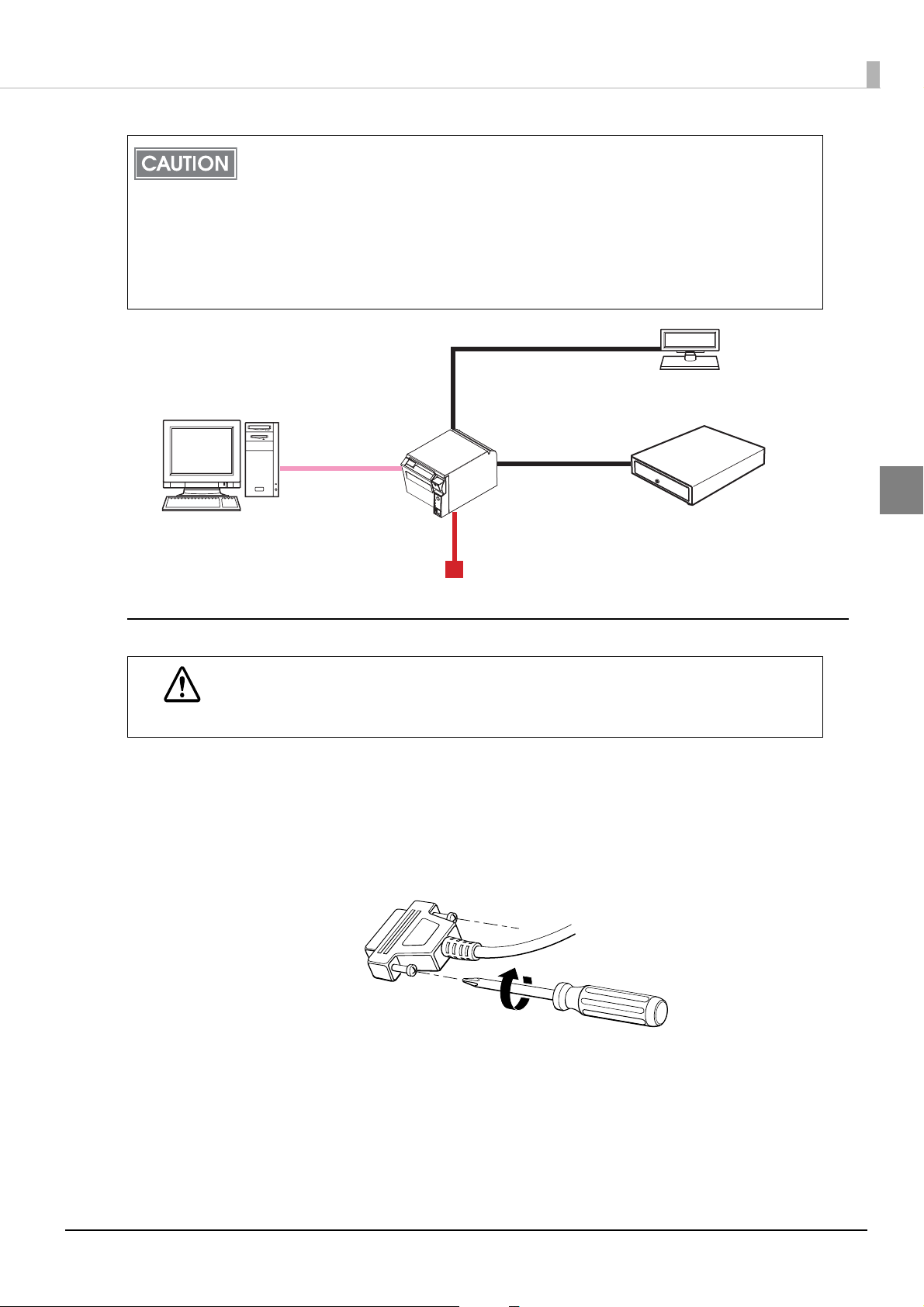
Connecting the serial interface (RS-232) cable
Be sure to turn off the power supply for both the printer and host computer before
connecting the cables.
WARNING
Insert the interface cable connector firmly into the interface connector on the connector
1
panel.
When using connectors equipped with screws, tighten them to secure the connectors
2
firmly.
When using interface cables equipped with a grounding line, attach the ground line to
3
the screw hole marked “FG” on the printer.
Connect the other end of the interface cable to the host computer.
4
25
Page 26
For Parallel Interface
DM-D
(Serial I/F model)
AC adapter + AC cable
Extension cable for
power supply
Parallel cable
Parallel cable
DM-D
(USB I/F model)
Modular cable
Modular cable
AC adapter + AC cable
Serial cable
USB cable
Cash drawer
Cash drawer
TM-T70II
TM-T70II
Parallel interface connection diagram
This printer is connected to the host computer via the parallel port. When a customer display (DM-D) is to be
connected, connect it to the host computer via the serial port or USB port.
• The modular cable is mounted on the cash drawer.
• Use the extension cable for power supply bundled with the customer display.
Connecting the parallel interface cable
1
2
3
4
26
Insert the interface cable connector firmly into the interface connector on the connector
panel.
Press down the clips on either side of the connector to lock it in place.
When using interface cables equipped with a ground line, attach the ground line to the
screw hole marked “FG” on the printer.
Connect the other end of the interface cable to the host computer.
Page 27
Chapter 2 Setup
DM-D
(Serial I/F model)
Serial cable
DM-D
(USB I/F model)
USB cable
Extension cable for
power supply
AC adapter + AC cable
Cash drawer
Cash drawer
Modular cable
Modular cable
TM-T70II
TM-T70II
AC adapter + AC cable
USB cable
USB cable
For USB Interface
USB interface connection diagram
When this printer is connected to the host computer by the USB interface, two connection forms are possible:
•Stand alone
• Y connection
• The modular cable is mounted on the cash drawer and the customer display.
• Use the extension cable for power supply bundled with the customer display.
Stand alone
This printer is connected to the host computer via the USB port. When a customer display (DM-D) is to be
connected, connect it to the host computer via the serial port or USB port.
2
Y connection (only for models with a customer display (DM-D) connector)
This printer is connected to the host computer via the USB port. When a customer display (DM-D) is to be
connected, connect it to the printer via the modular cable.
27
Page 28
• Make sure to pull out the power cable before connecting cables.
Modular cable
Modular cable
DM-D
Cash drawer
TM-T70II
USB cable
AC adapter + AC cable
Locking wire saddle
USB cable
USB upstream connector
• When connecting a customer display to the printer, connect the modular jack from the
customer display to the DM-D connector.
• Set the communication conditions of the customer display as follows:
∗ Baud rate: 19200 bps
∗ Bit length: 8-bit
∗ Parity: no parity
∗ Stop bit: 1
Connecting the USB interface cable
Attach the locking wire saddle at the location shown in the figure below.
1
Put the USB cable through the locking wire saddle.
2
Putting the USB cable through the locking wire saddle, as shown in the figure below, prevents the
cable from coming unplugged.
Connect the USB cable from the host computer to the USB upstream connector.
3
28
Page 29
Chapter 2 Setup
TM-T70II
TM-T70II
Modular cable
Cash drawer
10BASE-T/100BASE-TX
DM-D
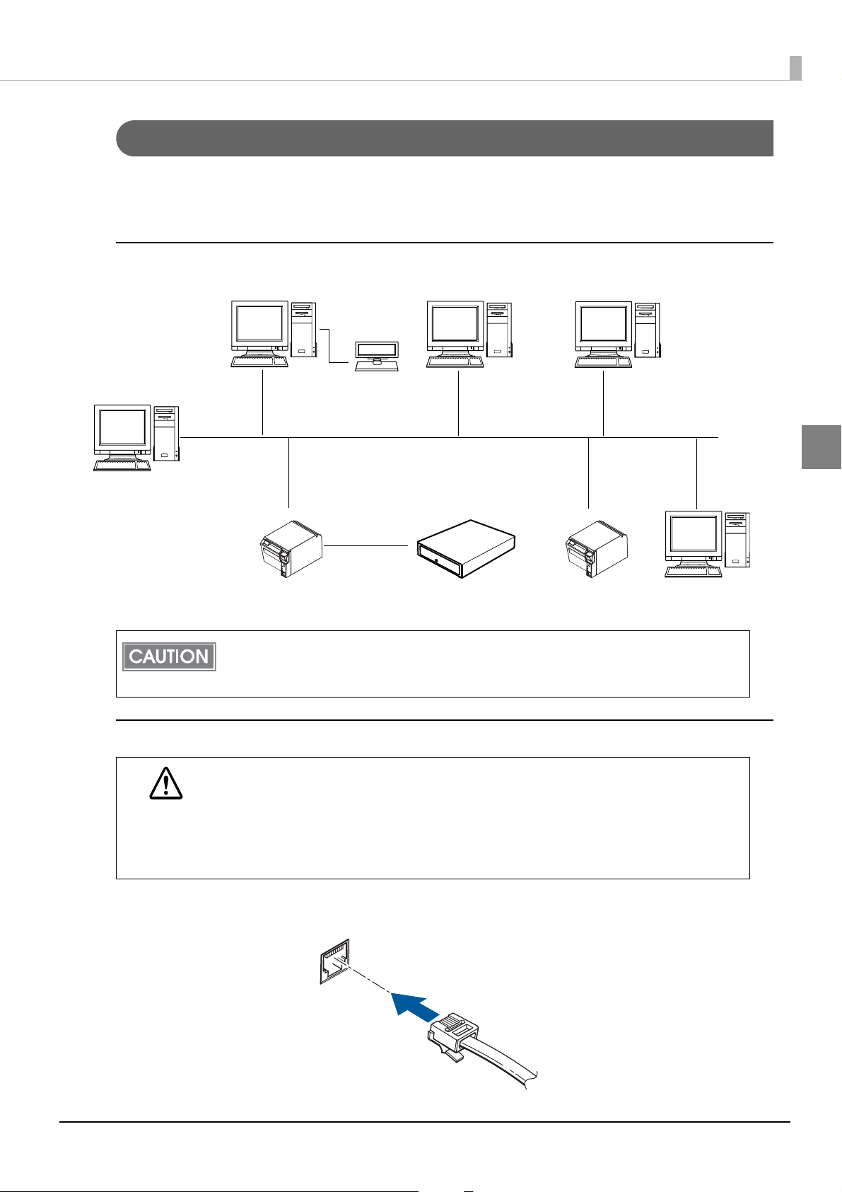
For LAN Interface
Connect the printer to a network by a LAN cable via a hub.
For the setting method of the IP address, see the Technical Reference Guide for the interface board.
LAN interface connection diagram
2
A customer display (DM-D series) cannot be connected to the printer when the printer is
connected to the host computer. To connect the customer display, connect the printer to the
host computer via the serial interface or the USB interface.
Connecting the LAN interface cable
• When LAN cables are installed outdoors, make sure devices without proper surge
protection are cushioned by being connected through devices that do have surge
CAUTION
Connect a 10BASE-T/100BASE-TX cable to the LAN connector by pressing firmly until the connector clicks
into place.
protection.
Otherwise, the devices can be damaged by lightning.
• Never attempt to connect the customer display cable, drawer kick-out cable, or the
standard telephone line cable to the LAN connector.
29
Page 30
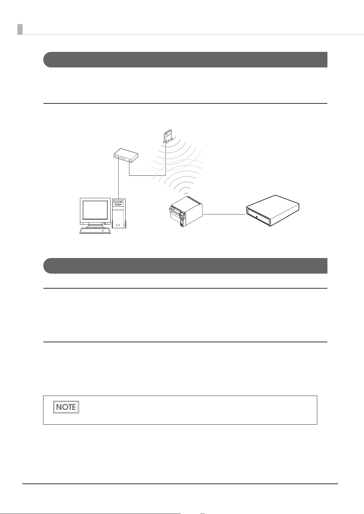
For Wireless LAN Interface
TM-T70II
Modular cable
Cash drawer
Access point
For details on how to set up a wireless LAN interface, see the Technical Reference Guide for the wireless LAN
interface board or the wireless LAN interface unit.
Wireless LAN interface connection diagram
For Bluetooth Interfaces
Connecting to smart devices
You can connect by using your smart device's Bluetooth connection settings as well as by using the Epson TM
Utility "Bluetooth Setup Wizard". See the iOS Bluetooth® TM Printer Technical Reference Guide for details on
connecting to iOS devices.
Connecting to Windows PCs
You can connect quickly and easily by using the EPSON TM Bluetooth® Connector utility. Start the utility, select
the search method, and then click [Search]. Select the printer you want to pair with, and then click [Connect]. If
a passkey entry screen is displayed, enter the Passkey, and then click [OK]. Select the port you want to use from
the drop-down list, and then click [OK]. The [Connection complete] screen is displayed.
• The device name displayed during pairing is TM-T70II_xxxxxx (where the last six digits are the
product serial number).
• The default Passkey is "0000".
30
Page 31

Connecting the AC Adapter
Power supply connector
Interface board
Use the PS-180 or an equivalent product as the AC adapter.
• Always use the PS-180 or an equivalent product as the AC adapter.
Using a nonstandard power supply can result in electric shock and fire.
WARNING
Connecting the AC Adapter
Make sure the printer’s power supply is turned off.
1
Connect the AC cable to the AC adapter.
2
Insert the DC cable onto the power supply connector (stamped 24V).
3
• Should a fault ever occur in the PS-180 or equivalent product, immediately turn off the
power to the printer and remove the power supply cable from the wall socket.
Chapter 2 Setup
2
Before removing the DC cable from the AC adapter, make sure the AC cable has been removed
from the AC adapter, then grasp the arrow-marked section of the connector and pull straight out.
31
Page 32

Setting the Memory Switches/Receipt Enhancement
With the memory switch and R/E (receipt enhancement) function, which are software settings for this printer,
you can set the various functions.
For an outline of the functions, see the following section. Use the methods shown in the table below; TM-T70II
Utility, Memory Switch Setting Mode, or ESC/POS commands, to set the memory switches and R/E functions.
Item\Method
Receive buffer capacity
BUSY condition
Processing when data receive error ✔✔✔
Auto line feed
USB power-saving function
Release condition of receive buffer BUSY ✔✔✔
Paper sensor to output paper-end signals default*
Error signal output
Print density ✔✔✔
Multi-tone print density
Print speed ✔✔✔
Number of head energizing parts ✔
Thai character print mode*
Character code table default ✔✔✔
Memory Switches
International character default ✔✔✔
2
1
TM-T70II
Utility
✔✔✔
✔✔✔
✔✔✔
✔✔✔
✔✔
✔✔✔
✔✔✔
Memory
Switch
Setting Mode
✔✔
ESC/POS
Commands
Interface selection
Autocutting after closing cover ✔✔✔
Customized Values
Paper reduction ✔✔✔
Font A auto replacement
Font B auto replacement ✔✔
Buzzer
TM-T70II command-compatible mode*
Communication condition of serial interface ✔✔✔
Communication condition of USB interface
Auto top logo ✔*
Auto bottom logo ✔✔
Receipt
Auto top/bottom logo extended functions
Enhancement
dpi: dots per inch
*1: Enabled only for the parallel interface
*2: Enabled only for South Asia font models
3
✔✔✔
✔✔✔
4
4
✔*
✔✔
✔✔
✔✔
✔
✔
32
Page 33

*3: Enabled only for ANK models
*4: Excluding some functions.
• For information about the TM-T70II Utility, see the TM-T70II Utility User’s Manual.
• For information about how to use the memory switch setting mode, see "Memory Switch
ting Mode" on page 52.
Set
or information about ESC/POS commands, see the ESC/POS Command Reference.
• F
Functions
Receive buffer capacity
• 4 KB (initial setting)
• 45 bytes
Chapter 2 Setup
BUSY condition
• Receive buffer full/Offline (initial setting)
• Receive buffer full
• In either case above, the printer enters the BUSY state after power is turned on, and when a
self-test is being run.
• If BUSY condition is set to “Receive buffer full,” the printer will not become BUSY
∗ When the cover is open
∗ When paper is fed by the Feed button
∗ When printing has stopped for a paper out
∗ When macro execution ready state
∗ When error has occurred
Processing when data receive error
• Prints “?” (initial setting)
•Ignored
Auto line feed
2
• Always disabled (initial setting)
•Always enabled
33
Page 34

USB power-saving function
•Disabled
• Enabled (initial setting)
The USB power-saving function is valid only when the USB interface communication condition is
set to the vendor-defined class and the system configuration is set so that the USB driver can
support the USB power-saving function.
Release condition of receive buffer BUSY
• Releases when the remaining receive buffer capacity becomes 256 bytes (initial setting)
• Releases when the remaining receive buffer capacity becomes 138 bytes
This function is enabled only when Receive buffer capacity is set to 4 KB.
Paper sensor to output paper-end signals default (only for parallel
interface models)
• Paper end sensor enabled, paper near-end sensor enabled
• Disabled (initial setting)
Error signal output
• Enabled (initial setting)
•Disabled
Print density
Selectable from levels 1 to 13 (70% ~ 130%)
Initial setting: level 7 (100%)
Depending on the paper type, it is recommended to set the print density as shown in the table below for the best
print quality.
Original Paper type Density Level
TF50KS-E, P220AGB-1, AF50KS-E Level 5 (90%)
TF60KS-E, PD160R, PD190R, KT48F20, KT55F20, F5041 Level 7 (100%)
P300, P310, P350 Level 8 (105%)
34
When the print density level is increased, printing speed may be reduced.
Page 35

Chapter 2 Setup
Multi-tone print density
Selectable from levels 1 to 13 (70% ~ 130%)
Initial setting for ANK models: level 7 (100%)
Initial setting for Simplified Chinese models, Traditional Chinese models, and South Asia font models: level 11
(120%)
• First change the print density, and then configure the Multi-tone print density.
• If you set the density too high, the contrast becomes lower. Select the density level checking
the overall tone balance of your image.
Print speed
Selectable from levels 1 to 13 (Slow ~ Fast)
Initial setting: level 13
Depending on print conditions, such as print duty, print head temperature, and data transmission
speed, print speed is automatically adjusted, which may cause white lines due to intermittent
print (the motor sometimes stops). To avoid this, keep the print speed constant by setting it
lower, or set the transmission speed higher for the serial interface.
Thai character print mode (only for South Asia font models)
•Thai 3 pass
• Thai 1 pass (initial setting)
Selecting the number of head energizing parts
• One-part energizing (initial setting)
• Two-part energizing
• Usually, the number of head energizing parts does not need to be changed.
• When printing at the maximum speed, select “One-part energizing.”
Character code table default
Selectable from 43 pages including user defined page
2
Initial setting: Page 0 (PC437: USA, Standard Europe)
• For the character code table, see "Character Code Tables" on page 101.
• User-
defined page is not supported by South Asia font models.
35
Page 36

International character default
Selectable from 18 sets
Initial setting for Simplified Chinese models: China
Initial setting for ANK models, Traditional Chinese models, and South Asia font models: USA
For the character code table, see "Character Code Tables" on page 101.
Interface selection
Selectable from: automatic selection (initial setting), fixed to UIB interface, or fixed to built-in USB. The table
below describes the modes you can set for the printer to control the dual interfaces.
UIB interface
Interface mode
Automatic selection
Serial/Parallel
Available
*1
Interface other than
Serial/Parallel
Available
*2
Built-in USB
Available
*1,*2
Fixed to UIB
Fixed to built-in USB
For printers on which the standard USB connector has a cap, you cannot use the standard USB
interface.
• Automatic selection
∗ *1: The interface of either the serial/parallel or built-in USB to which data is transmitted first
is selected.
∗ *2: When the USB cable is connected with a host PC, the USB interface is selected.
• Once the interface is selected, the selection is enabled until the power is turned off or the
printer is reset.
Available Available Not available
Not available Not available Available
Autocutting after closing cover
•Cuts
• Does not cut (initial setting)
Paper reduction
Extra upper space reduction
• Disabled (initial setting)
•Enabled
36
Page 37

Extra lower space reduction
• Disabled (initial setting)
•Enabled
Line space reduction rate
• Not reduced (initial setting)
• 25%
• 50%
• 75%
Line feed reduction rate
• Not reduced (initial setting)
• 25%
• 50%
• 75%
Chapter 2 Setup
2
Barcode height reduction rate
• Not reduced (initial setting)
• 25%
• 50%
• 75%
• Paper reduction is not performed for space dot lines of graphics printing data.
• When reducing barcode height, be sure to check reading a barcode with your barcode reader
in advance.
Font A auto replacement
• Does not replace (initial setting)
•Font B
Font B auto replacement
• Does not replace (initial setting)
•Font A
37
Page 38

Buzzer
• For models without the internal buzzer function, the optional external buzzer (OT-BZ20) needs
to be connected to use the buzzer function. For information about how to connect the
optional external buzzer, see "Connecting the Optional External Buzzer" on page 42.
• When the
disable it when you use a cash drawer.
Enables/disables
•Disabled
• Optional external buzzer is enabled
• Internal buzzer is enabled (initial setting)
Buzzer frequency (Error) (only for the optional external buzzer)
•Does not sound
•Sounds 1 time
• Sounds continuously (initial setting)
Sound pattern (Autocut) (only for the optional external buzzer)
Selectable from Patterns A to E
optional external buzzer is enabled, a cash drawer cannot be used. Be sure to
Initial setting: Pattern A
Buzzer frequency (Autocut) (only for the optional external buzzer)
•Does not sound
• Sounds 1 time (initial setting)
Sound pattern (Pulse 1) (only for the optional external buzzer)
Selectable from Patterns A to E
Initial setting: Pattern A
Buzzer frequency (Pulse 1)
• Does not sound (initial setting)
• Sounds 1 time
Sound pattern (Pulse 2) (only for the optional external buzzer)
Selectable from Patterns A to E
Initial setting: Pattern B
Buzzer frequency (Pulse 2)
•Does not sound
• Sounds 1 time (initial setting)
38
Page 39

Chapter 2 Setup
TM-T70II command-compatible mode (only for ANK models)
• Disabled (initial setting)
•Enabled
Communication condition of serial interface
Transmission speed
• 2400 bps
• 4800 bps
• 9600 bps
• 19200 bps
• 38400 bps (initial setting for ANK models (with TM-T70II command-compatible mode enabled))
• 57600 bps
• 115200 bps (initial setting for ANK models (with TM-T70II command-compatible mode disabled),
South Asia font models, Simplified Chinese models and Traditional Chinese models)
[bps: bits per second]
2
Parity
• None (initial setting)
•Even
•Odd
Data bit
•7 bits
• 8 bits (initial setting)
If set to 7 bits, printing from a printer driver is not possible.
Flow control
• DTR/DSR (initial setting)
• XON/XOFF
Communication condition of USB interface
• USB printer class
• USB vendor-defined class (initial setting)
39
Page 40

Auto top logo
TM-T70II Utility does not support the function for Number of lines to be deleted below top logo.
Key-code
Selectable from key-codes of registered logos
Alignment
• Left (initial setting)
•Center
•Right
Number of lines to be deleted below top logo
Auto bottom logo
Key-code
Selectable from key-codes of registered logos
Alignment
• Left (initial setting)
•Center
•Right
Auto top/bottom logo extended functions
TM-T70II Utility does not support the following functions.
• Top logo print while paper feeding to the cutting position
• Top logo print while clearing the buffer to recover from a recoverable error
• Top logo print after paper feeding with the Feed button has finished
Top logo print while paper feeding to the cutting position
•Disabled
• Enabled (initial setting)
Top logo print when printer is powered on
• Disabled (initial setting)
•Enabled
Top logo print when roll paper cover is closed
•Disabled
• Enabled (initial setting)
40
Page 41

Top logo print while clearing the buffer to recover from a recoverable error
•Disabled
• Enabled (initial setting)
Top logo print after paper feeding with the Feed button has finished
• Disabled (initial setting)
•Enabled
Chapter 2 Setup
2
41
Page 42

Connecting the Optional External Buzzer
Optional external buzzer
Affixing tape
(1 pair, 2 pieces)
User’s Manual
When using the optional external buzzer (OT-BZ20), install the optional external buzzer.
If your printer is not equipped with a buzzer, you can use the optional external buzzer (OT-BZ20) by
connecting it to the drawer.
• The optional external buzzer and the drawer cannot be used together at the same time.
• If you configure the memory switch setting to enable the optional external buzzer, the drawer
cannot be opened because the pulse is not sent to the drawer kick connector pin.
• Make sure to use the accessory affixing tape to attach the optional external buzzer to the
printer.
• Be careful not to spill water, oil, solvent, or any other liquid over the printer. Doing so may
result in malfunction of the printer.
Unpacking
Open the package and confirm that it contains all of the parts listed in the illustration. If any parts are missing
or damaged, please contact your dealer for assistance.
Installation Position
This product is recommended to be installed in the following position.
•Either side of the printer.
• Do not install the optional external buzzer at the roll paper exit.
• To prevent liquid from entering inside, it is recommended to install the optional external
buzzer so that the volume adjustment knob is positioned sideways or downward. (For details
of the volume adjustment knob, see "Adjusting the Buzzer Volume" on page 44.)
42
Page 43

Installation Procedures
Affixing tape
Drawer kick connector
Turn off the printer.
1
Connect and disconnect the optional external buzzer while the printer is turned off. If you
connect it while the printer is turned on, the buzzer does not function correctly.
Clean and dry the printer case where the optional external buzzer will be installed.
2
With 2 pieces of the affixing tape combined, peel off the sticker on one side, and paste it
3
around the center of the attaching surface of the optional external buzzer.
Chapter 2 Setup
2
Connect the cable of the optional external buzzer to the drawer kick connector on the
4
printer.
• Be sure to connect to the drawer kick connector on the applicable printer.
• Do not connect both the optional external buzzer and the drawer by using a splitter or similar
device.
43
Page 44

Peel off the sticker on the other side of the affixing tape, and attach and fix the optional
Printer case
Volume adjustment knob
High
Low
5
external buzzer to the printer case.
Turn on the printer.
6
Make settings for the optional external buzzer on the printer.
7
• To use this product, be sure to enable the optional external buzzer with the printer setting.
• When the optional external buzzer is enabled with the printer setting, the drawer cannot be
driven.
Adjusting the Buzzer Volume
Turn the volume adjustment knob to adjust the buzzer volume.
Setting the Optional External Buzzer
You need to set the memory switches for buzzer enable/disable setting, sound pattern setting, and frequency
setting. For information about the memory switches, see "Setting the Memory Switches/Receipt Enhancement"
on page 32.
44
Page 45

Connecting the Cash Drawer
Use the cash drawer handled by EPSON or your dealer.
Connecting the Drawer Kick-out Cable
• Specifications of drawers differ depending on makers or models. When you use a drawer
other than specified, make sure its specification meets the following conditions.
WARNING
Otherwise, devices may be damaged.
∗ The load, such as a drawer kick-out solenoid, must be connected between pins 4 and 2 or
pins 4 and 5 of the drawer kick connector.
∗ When the drawer open/close signal is used, a switch must be provided between drawer kick
connector pins 3 and 6.
∗ The resistance of the load, such as a drawer kick-out solenoid, must be 24 Ω or more or the
input current must be 1 A or less.
∗ Be sure to use the 24 V power output on drawer kick connector pin 4 for driving the equip-
ment.
• Use a shield cable for the drawer connector cable.
• Two driver transistors cannot be energized simultaneously.
• Leave intervals longer than 4 times the drawer driving pulse when sending it
continuously.
• Be sure to use the printer power supply (connector pin 4) for the drawer power source.
• Do not insert a telephone line into the drawer kick connector.
Doing so may damage the telephone line or printer.
Chapter 2 Setup
2
Connect the connector of the drawer kick-out cable to the printer.
45
Page 46

Drawer connection diagram
With shielded
Drawer kick connector
Printer side
User side [Drawer kick-out side]
Drawer open/close switch
Drawer kick-out solenoid
Control device
Setting the Internal Buzzer (for Models with an Internal Buzzer)
Models with the buzzer function can beep the buzzer when the drawer is opened, by setting the properties of
the driver or outputting a pulse signal by a command. The internal buzzer cannot change the buzzer volume
and sound pattern but can change the buzzer frequency. When using the internal buzzer, you need to enable the
internal buzzer with the memory switch.
The buzzer setting is performed by setting the memory switches for the buzzer and specifying connector pin
numbers to which a command outputs a pulse signal, as shown in the table below. For information about the
memory switches, see "Setting the Memory Switches/Receipt Enhancement" on page 32
Memory
switch
Buzzer
frequency
(Pulse 1)
Buzzer
frequency
(Pulse 2)
Specified connector pin ON OFF Initial setting
Drawer kick connector pin 2 Buzzer beeps.
Drawer kick connector pin 5 Buzzer beeps.
Since the buzzer drive signal and the cash drawer drive signal are common in the printer, do not
use the same connector pin numbers to output the signal for the buzzer and the cash drawer.
• For detailed information about ESC/POS commands, see the ESC/POS Command Reference.
• For detailed information about the driver control, see the manual for each driver.
Buzzer does not
beep.
Buzzer does not
beep.
OFF
ON
46
Page 47

Chapter 3 Setting/Checking Modes
Setting/Checking Modes
Besides the ordinary print mode, the printer has the following modes to set or check settings of the printer.
• Self-test Mode
• Hexadecimal Dumping Mode (page 49)
NV Graphics Information Print Mode (page 50)
•
Receipt Enhancement Information Print Mode (page 51)
•
• Memory Switch Setting Mode (page 52)
Self-test Mode
You can confirm the following information by running the self-test mode.
• Control ROM version
• Interface type
• Receive buffer size
• Busy conditions (depending on the interface type)
• Mounted multilingual fonts
• Thai character print mode (only for South Asia font models)
• Auto line feed (with a parallel interface)
•Print density
• TM-T70II command-compatible mode (only for ANK models)
• Maintenance counter information (head running length, number of times of autocutting)
• Memory switch settings
Follow the steps below to run this mode.
Close the roll paper cover.
1
While pressing the Feed button, turn on the printer. (Keep pressing the Feed button
2
until the printer starts printing.)
The printer starts printing current status of the printer.
3
With the LAN interface, before printing starts, it takes 6 seconds if the IP address is fixed and 13
seconds if the IP address is obtained with the automatic setting. (It may take longer depending
on the response time from the host.)
When the printer finishes printing the printer status, the following message is printed and the Paper LED
flashes. (The printer is now in the self-test wait mode.):
“Select Modes by pressing Feed button.
Continue SELF-TEST: Less than 1 second
47
Page 48

Mode Selection : 1 second or more”
Press the Feed button while the printer is in the self-test wait mode.
3
If you select the SELF-TEST, the printer prints a rolling pattern using only the built-in character set.
If you select the mode selection, follow the instructions printed by the printer.
After printing the following message, the printer is initialized and returned to the normal mode.
“*** completed***”
48
Page 49

Chapter 3 Setting/Checking Modes
Hexadecimal Dumping Mode
In the hexadecimal dumping mode, the printer prints the data transmitted from a host computer in
hexadecimal numbers and their corresponding characters.
Follow the steps below to run this mode.
• If there is no character corresponding to print data, “.” is printed.
• If print data is less than one line, press the Feed button to print the line.
• Applications that confirm printer status may not work correctly during the hexadecimal
dumping mode. The printer returns only the status for “Transmit real-time status.”
Open the roll paper cover.
1
While pressing the Feed button, turn on the printer.
2
Close the roll paper cover.
3
The printer starts printing data received from then on in hexadecimal numbers and their corresponding
characters.
Printing example:
Turn off the printer or press the Feed button three times to return to the normal mode.
3
49
Page 50

NV Graphics Information Print Mode
You can confirm the following information by running the NV graphics information print mode:
• Capacity of the NV graphics
• Used capacity of the NV graphics
• Unused capacity of the NV graphics
• Number of NV graphics that are registered
• Key code, number of dots in X direction, number of dots in Y direction, number of colors to be defined.
• NV graphics data
For detailed information about NV graphics, see "NV Graphics Memory" on page 19.
Follow the steps below to run this mode.
Close the roll paper cover.
1
While pressing the Feed button, turn on the printer. (Keep pressing the Feed button
2
until the printer starts printing.)
The printer starts printing current status of the printer.
With the LAN interface, before printing starts, it takes 6 seconds if the IP address is fixed and 13
seconds if the IP address is obtained with the automatic setting. (It may take longer depending
on the response time from the host.)
After the printing has been completed, press the Feed button for more than one second.
3
The printer starts printing instructions.
After the printing has been completed, press the Feed button.
4
Then press the Feed button for more than one second.
5
Turn the power off and on to return to the normal mode.
50
Page 51

Chapter 3 Setting/Checking Modes
R/E (Receipt Enhancement) Information Print Mode
You can confirm the following information by running the R/E information mode:
• Automatic top logo setting
• Automatic bottom logo setting
• Extended settings for automatic top/bottom logo
Follow the steps below to run this mode.
Close the roll paper cover.
1
While pressing the Feed button, turn the power on. (Keep pressing the Feed button
2
until the printer starts printing.)
The printer prints current status of the printer.
With the LAN interface, before printing starts, it takes 6 seconds if the IP address is fixed and 13
seconds if the IP address is obtained with the automatic setting. (It may take longer depending
on the response time from the host.)
After the printing has been completed, press the Feed button for more than one sec-
3
ond.
The printer starts printing instructions.
After the printing has been completed, press the Feed button twice.
4
Then press the Feed button for more than one second.
5
Turn the power off and on to return to the normal mode.
3
51
Page 52

Memory Switch Setting Mode
You can configure the memory switches of the printer.
• Receive buffer capacity • BUSY condition
• Processing when data receive error • Auto line feed
• USB power-saving function • Release condition of receive buffer BUSY
• Error signal output • Print density
• Multi-tone print density • Print speed
• Character code table default • International character default
• Interface selection • Autocutting after closing cover
• Auto paper reduction • Font auto replacement
• Buzzer control • Communication condition of serial interface
• Communication condition of USB interface • TM-T70II command-compatible mode (only for ANK
models)
For detailed information about memory switches, see "Setting the Memory Switches/Receipt
Enhancement" on page 32.
Starting the memory switch setting mode
Follow the steps below to run this mode.
Close the roll paper cover.
1
Turn on the printer while pressing the Feed button. (Keep pressing the Feed button until
2
the printer starts printing.)
The printer prints current status of the printer.
ith the LAN interface, before printing starts, it takes 6 seconds if the IP address is fixed and 13
W
seconds if the IP address is obtained with the automatic setting. (It may take longer depending
on the response time from the host.)
After the printing has been completed, press the Feed button for more than one second.
3
The printer starts printing instructions.
52
Page 53

Chapter 3 Setting/Checking Modes
After the printing has been completed, press the Feed button three times.
4
Then press the Feed button for more than one second.
5
The printer starts printing instructions for settings. Follow the instructions.
After one setting has been completed, the printer stores the setting and then starts initializing. After that, the
printer returns to the normal mode.
3
53
Page 54

Setting the memory switch
Follow the steps below to run this mode.
Enter the memory switch setting mode.
1. Check that the roll paper is set and that the printer is turned off.
2. While pressing the Feed button, turn on the printer. Keep pressing the Feed button until the printer starts
printing.
3. When the printer finishes printing the printer status, press the Feed button. Keep pressing the Feed button
until the printer starts printing.
4. Press the Feed button three times.
5. Then press the Feed button. Keep pressing the Feed button until the printer starts printing.
The printer starts printing instructions for settings. Follow the instructions.
Select the setting item
Select the setting item by the number of times the Feed button is pressed as follows.
When the Feed button is not pressed (0 times) or it is pressed more than 12 times, this mode finishes.
❏ 1: Print Current Settings
❏ 2: Print Density
❏ 3: Serial Interface Settings
❏ 4: Automatic Paper Reduction
❏ 5: Auto Paper Feed&Cut at
cover close
❏ 6: Default Character
❏ 7: Embedded Font Replacement
❏ 8: Interface Selection
❏ 9: USB Interface Settings
❏ 10: Printing Speed
❏ 11: Other Settings
When the button is pressed
less than or more than shown
on the left, the setting has
not been changed.
Set the conditions
You can make settings for each condition per setting item by the number of times the Feed button is pressed.
❏ Print Current Settings
❏ Print Density (page 55)
rial Interface Settings (page 55)
❏ Se
utomatic Paper Reduction (page 55)
❏ A
❏ Auto Paper Feed&Cut at cover close (page 55)
❏ Default C
haracter (page 56)
edded Font Replacement (page 56)
❏ Emb
❏ In
terface Selection (page 56)
B Interface Settings (page 56)
❏ US
rinting Speed (page 57)
❏ P
❏ Other Settings (page 57)
Finish the memory switch setting mode
Turn off the printer. Print out the new settings and save them to the NV memory. Software is reset, and the
printer is ready to print.
54
Page 55

Chapter 3 Setting/Checking Modes
Setting conditions
•Print Density
Number of times to press the Feed button Settings
0No change
1 Monochrome
2 Multi-Tone
• Serial Interface Settings
Number of times to press the Feed button Settings
0No change
1Baud Rate
2Parity
3 Handshaking
4 Data Bits
5 Data Receive Error
•Automatic Paper Reduction
Number of times to press the Feed button Settings
0No change
1Upper Margin
2Lower Margin
3 Blank Line Spacing
4Blank Space
5 Barcode Height
• Auto Paper Feed&Cut at cover close
Number of times to press the Feed button Settings
0No change
1Enable
3
2Disable
55
Page 56

• Default Character
Number of times to press the Feed button Settings
0No change
1Code Page
2 International Character Set
• Embedded Font Replacement
Number of times to press the Feed button Settings
0No change
1 Font A Replacement
2 Font B Replacement
•Interface Selection
Number of times to press the Feed button Settings
0No change
1UIB
2 Built-in USB
3Auto
• USB Interface Settings
Number of times to press the Feed button Settings
0No change
1Class
2 USB Power Saving
56
Page 57

Chapter 3 Setting/Checking Modes
• Printing Speed
Number of times to press the Feed button Settings
0No change
1 Level 1 (Slow)
2 Level 2
3 Level 3
4 Level 4
5 Level 5
6 Level 6
7 Level 7
8 Level 8
9 Level 9
10 Level 10
11 Level 11
12 Level 12
13 Level 13 (Fast)
• Other Settings
Number of times to press the Feed button Settings
0No change
1 TM-T70II Compatible Mode
2Buzzer Control
3Interface Settings
3
57
Page 58

58
Page 59

Chapter 4 Application Development Information
Application Development Information
This chapter describes how to control the printer and gives information useful for printer application
development.
Controlling the Printer
The printer supports the following command systems:
•ESC/POS
Users can control the printer by using the aforementioned command, or the following development kits or
drivers.
•OPOS ADK
• OPOS ADK for .NET
•JavaPOS ADK
• EPSON Advanced Printer Driver (APD)
• ePOS-Print SDK (for Android/iOS/Windows Store Apps/JavaScript)
ESC/POS
ESC/POS is the Epson original printer command system for POS printers and customer display. With ESC/POS
commands, you can directly control all the printer functions, but detailed knowledge of printer specifications or
combination of commands is required, compared to using drivers and applications.
For detailed information about ESC/POS commands, see the ESC/POS Command Reference that can be
accessed from the following URL.
www.epson-biz.com/pos/reference/
4
59
Page 60

Controlling the Cash Drawer
A pulse output is sent to drawer kick connector pin 2 or pin 5, and you can open the drawer.
You can also check the open/close status of the drawer by checking the signal level of the drawer kick connector
pin 3.
These controls are executed by a driver or by commands.
ESC/POS Commands
Prepare the output command for the specified pulse and the status transmission command.
For details, see the ESC/POS Command Reference.
For Windows Printer Drivers (APD)
You can set so that the drawer opens at the start/end of printing or start/end of a page. For details, see the
manual for drivers.
For details on control, see the manual for Status API of the driver.
OPOS (OCX Driver)
Register a cash drawer using the SetupPOS Utility, and control using the OpenDrawer method or the DirectIO
function.
For details, see the "EPSON OPOS ADK MANUAL APPLICATION DEVELOPMENT GUIDE Cash Drawer"
and the "UnifiedPOS Specification".
OPOS for .NET
Register a cash drawer using the SetupPOS Utility, and control using the OpenDrawer method or the DirectIO
function.
For details, see the "EPSON OPOS ADK for .NET MANUAL Application Development Guide Cash Drawer
(EPSON Standard)" and the "UnifiedPOS Specification".
ePOS-Print SDK
The output command for the drawer kick pulse and the status transmission command are provided in each
SDK library. For details, see the user's manuals provided with each SDK.
• Whether or not pin 2 or pin 5 operates the drawer kick connector depends on the connected
cash drawer.
• You can acquire documents regarding the UnifiedPOS from the following link.
https://www.omg.org/retail/unified-pos.htm
60
Page 61

Chapter 4 Application Development Information
Controlling the Built-in Buzzer
For specifications with a built-in buzzer, a pulse output is sent to the operating pin for the drawer kick
connector, and the built-in buzzer beeps.
You cannot change the volume or the sound emitted, but you can change the buzzing time by changing the
signal pulse width.
This is controlled by a driver or by commands.
ESC/POS Commands
The output command for the specified pulse is used.
For details, see the ESC/POS Command Reference.
For Windows Printer Drivers (APD)
You can set so that the buzzer beeps at the start/end of printing or start/end of a page. For details, see the
manual for drivers.
For API, the API for opening the drawer is used. For details, see the manual for Status API of the driver.
OPOS (OCX Driver)
Register a POS printer using the SetupPOS Utility and control using the DirectIO function.
For details, see the "EPSON OPOS ADK MANUAL APPLICATION DEVELOPMENT GUIDE POSPrinter
(TM Series)".
OPOS for .NET
Register a POS printer using the SetupPOS Utility and control using the DirectIO function.
For details, see the "EPSON OPOS ADK for .NET MANUAL Application Development Guide POSPrinter
(TM-T70II)".
ePOS-Print SDK
Use the output command for the drawer kick pulse provided in each SDK library. For details, see the user's
manuals provided with each SDK.
When using a cash drawer operated by pin 5 with a built-in buzzer, you need to change the DIP
switch settings for the buzzer circuit so that the buzzer beeps from a pulse signal for pin 2. For
details, see "Setting the Internal Buzzer (for Models with an Internal Buzzer)" on page 46.
4
61
Page 62

Controlling the Optional External Buzzer
You can set the optional external buzzer to buzz when an error occurs and when an automatic cut off occurs.
The buzzer can be buzzed using a driver or a command.
You can also set the timing and the beep pattern for the buzzer.
ESC/POS Command
Use the buzzer control command or the output command for the specified pulse.
For details, see the ESC/POS Command Reference.
For Windows Printer Drivers (APD)
You can set so that the buzzer beeps at the start/end of printing or start/end of a page. For details, see the
manual for drivers.
For API, use the DirectIO function or the API for opening the drawer. For details, see the manual for Status API
of the drivers.
OPOS (OCX Driver)
Register a POS printer using the SetupPOS Utility and control using the DirectIO function.
For details, see the "EPSON OPOS ADK MANUAL APPLICATION DEVELOPMENT GUIDE POSPrinter
(TM Series)".
OPOS for .NET
Register a POS printer using the SetupPOS Utility and control using the DirectIO function.
For details, see the "EPSON OPOS ADK for .NET MANUAL Application Development Guide POSPrinter
(TM-T70II)".
ePOS-Print SDK
The command for the buzzer function is provided in each SDK library. For details, see the user's manuals
provided with each SDK.
For details on setting the optional external buzzer, see "Connecting the Optional External Buzzer"
on page 42.
62
Page 63

Chapter 4 Application Development Information
Software and Manuals
The following software and manuals are provided for application development.
Development Kits
Software Description Targ e t m odel
ePOS-Print SDK This development kit is for controlling the printer
for Android Ethernet/ Wireless LAN /
for iOS Ethernet / Wireless LAN /
for Windows Store Apps Ethernet / Wireless LAN /
from Web applications and native applications of
smart devices. It includes libraries, manuals, and
sample programs.
Bluetooth / USB
Bluetooth
Bluetooth
for JavaScript Ethernet
*1: Except for models with the following interface boards.
UB-E02, UB-E02A, UB-E03
*2: Except for models with the following interface boards.
UB-R02, UB-R02A, UB-R03, UB-R03A
Software Description
EPSON OPOS ADK This OCX driver can control POS peripherals using OLE
technology*
original commands is not required on the application side,
efficient system development is possible.
EPSON OPOS ADK for .NET The OPOS ADK for .NET is a POS industry standard printer driver
compatible with Microsoft POS for .NET.
It allows you to develop applications that are compatible with
the UPOS (Unified POS) specification.
When developing applications, use a separate development
environment such as Microsoft Visual Studio .NET.
1
. Because controlling POS peripherals with
*1
/ Wireless LAN
Operating
environment
Windows
Windows
*2
4
63
Page 64

Software Description
Operating
environment
JavaPOS ADK JavaPOS is the standard specification which defines an
architecture and device interface (API) to access various POS
devices from a Java based system.
Using JavaPOS standard API allows control with Java based
applications of functions inherent to each device.
A flexible design with Java language and JavaPOS enables
many different types of computer systems, such as stand alone
or network configuration, to use a same application.
You can use JavaPOS to build applications and drivers
independently of platforms.
This allows flexible configurations using thin clients to meet the
system requirements.
Windows, Linux
*1: OLE technology developed by Microsoft divides software into part blocks.
The OPOS driver is presupposed to be used with a development environment such as Visual Basic, unlike
ordinary Windows printer drivers. It is not a driver to be used for printing from commercial applications.
Drivers
Software Description
Operating
environment
EPSON Advanced Printer
Driver (APD)
EPSON TM Virtual Port Driver This is a serial/parallel-USB/LAN conversion driver to make an
TM-T70II Mac Printer Driver Mac printer driver allows you to control the TM-T70II using
In addition to ordinary Windows printer driver functions, this
driver has controls specific to POS. The Status API (Epson
original DLL) that monitors printer status and sends ESC/POS
commands is also attached to this driver.
Epson TM/BA/EU printer connected via USB or LAN accessible
from a POS application through a virtual serial or parallel port. It
allows you to directly control devices connected via USB or LAN
with ESC/POS commands without making changes in the POS
application that controls devices connected via a serial or
parallel interface.
Common UNIX Printing System (CUPS) on Mac OS X.
This is a full raster printer driver. It is able to print images, text,
and vector graphics etc., that an application displays. With this
driver many printer controls are possible, such as paper cut
timing control, cash drawer control, print speed control, blank
line skip, and upside-down printing. It also provides API and
dialogues for print setting, sample applications, and logo
setting utility.
Windows
Windows
Mac
64
Page 65

Chapter 4 Application Development Information
Software Description
Epson TM/BA Series Thermal
Printer Driver
This driver allows you to control the TM-T70II using Common
UNIX Printing System (CUPS) on GNU/Linux.
This is a full raster printer driver. It is able to print images, text,
and vector graphics etc., that an application displays. With this
driver many printer control are possible, such as paper cut
timing control, cash drawer control, print speed control, blank
line skip, and upside-down printing.
Utilities
Software Description
TM-T70II Utility A utility for checking and changing various printer settings. Use
this utility to:
• Checking current settings
• Operation check
• Storing logos
• Coupon settings
• Paper reduction settings
• Automatic paper cut settings
• Printing control settings
• Font settings
• Optional buzzer settings
• Communication I/F settings
• Backup/restore
Operating
environment
Linux
Operating
environment
Windows
4
EpsonNet Config A network setting tool for Epson network products.
In the case of this printer, you can use this tool to check and/or
set network parameters by connecting the Wireless LAN model
to a computer for setup via the USB interface.
Monitoring Tool Use to check a list of status for the Epson printers connected to
the network.
Deployment Tool Use to make network and printer settings simultaneously, via
USB. Allows you to make settings efficiently at the time of
introducing TM printers for the first time, or when configuring
multiple TM printers at the same time.
BmpToRaster This is a command line and GUI utility that converts Windows
BMP files to raster graphics data for ESC/POS commands. You
can create a variety of multiple tone or monochrome image
print data. You can print graphics by sending the created binary
file to the printer as it is.
Windows, Mac
Windows
Windows
Windows
65
Page 66

Download
You can obtain software and manuals from one of the following URLs.
For customers in North America, go to the following web site:
www.epson.com/support/
For customers in other countries, go to the following web site:
www.epson-biz.com/
66
Page 67

Handling
This chapter describes basic handling of the printer.
Installing and Replacing Roll Paper
• Do not open the roll paper cover during printing.
The printer may be damaged.
WARNING
• Do not touch the manual cutter with your hands when installing or replacing the roll
paper.
Otherwise, you may be injured because the manual cutter blade is sharp.
• Use roll paper that meets the printer specification. For details about paper specification, see
"Paper Specifications" on page 88.
aper must not be pasted to the roll paper spool.
• P
Chapter 5 Handling
Press the cover open lever to open the roll paper cover.
1
Remove the used roll paper core, if any.
2
In the correct direction of the roll paper, install the roll paper.
3
5
67
Page 68

Pull out some roll paper, and make sure that the roll paper is set between the paper
Paper guides
4
guides.
Close the roll paper cover.
5
Tear off the roll paper.
6
68
Page 69

Chapter 5 Handling
Thermal head
Removing Jammed Paper
Do not touch the thermal head (See"Cleaning the Thermal Head" on page 69.) because it
can be very hot after printing.
CAUTION
Turn off the printer and press the cover open lever to open the roll paper cover.
1
Remove the jammed paper, reinstall the roll, and close the roll paper cover.
2
Cleaning the Thermal Head
Epson recommends cleaning the thermal head periodically (generally every 3 months) to maintain receipt print
quality.
After printing, the thermal head can be very hot. Do not touch it and let it cool before you
clean it. Do not damage the thermal head by touching it with your fingers or any hard
CAUTION
object.
Turn off the printer and open the printer cover. Clean the thermal elements of the thermal head with a cotton
swab moistened with an alcohol solvent (ethanol or IPA).
5
69
Page 70

Preparing for Transport
Follow the steps below to transport the printer.
Turn off the printer.
1
Confirm that LED is off.
2
Remove the power supply connector.
3
Remove the roll paper.
4
Pack the printer upright.
5
70
Page 71

Chapter 6 Replacement of the TM-T70
Replacement of the TM-T70
The TM-T70II is designed so that it can smoothly replace the TM-T70. This chapter describes precautions for
the replacement.
Compatibility
Printing
The printing and character specifications are the same as those of the TM-T70. Without special configurations,
the TM-T70II prints the same results as the TM-T70 prints.
Print Density
The print density of the TM-T70II can be set with the memory switch as can the TM-T70.
For detailed information about the memory switch, see "Setting the Memory Switches/Receipt
Enhancement" on page 32.
Number of Head Energizing Parts
For the TM-T70II, the initial setting of the number of head energizing parts is “One-part energizing.” You can
change the setting with the memory switch (See "Setting the Memory Switches/Receipt Enhancement" on page
32.); however it does not usually need to be changed.
TM-T70II TM-T70
• One-part energizing
• Two-part energizing
Number of head energizing parts
• 58 mm width paper printing
One-part energizing/Two-part
energizing/Auto energizing
• 80 mm width paper printing
One-part energizing/Two-part
energizing
6
Printable Area (for 80 mm Width Paper/58 mm Width Paper)
The printable area (left/right margins, print start position from the autocutting position, print start position
from the manual cutting position) of the TM-T70II is the same as that of the TM-T70.
71
Page 72

Cutting Method
The TM-T70II uses the partial cutting method (cutting with one point in left edge left uncut) as does the
TM-T70.
Manual Paper Feed
Manual paper feed is not possible with the TM-T70II while it is possible with the TM-T70 after printing pauses.
Receive Buffer
You can set the receive buffer of the TM-T70II to 4 KB or 45 bytes with the memory switch, while you can set
the receive buffer of the TM-T70 with the DIP switch. The buffer full condition and buffer full release condition
of the TM-T70II are the same as those of the TM-T70.
Memory Capacity
The sizes of the download buffer and NV graphics data of the TM-T70II are the same as those of the TM-T70.
Electrical Characteristics
The operating voltage of the TM-T70II is DC 24 ± 7%, the same as the TM-T70. The current consumption
differs, depending on the print duty.
DIP Switches
TM-T70II does not have DIP switches; however, various functions can be set with memory switches. For
detailed information about the memory switches, see "Setting the Memory Switches/Receipt Enhancement" on
pa
ge 32.
Printer Status
The TM-T70II goes to the same status under the same conditions as the TM-T70. You can replace the TM-
T70II with the TM-T70 without modifying applications.
72
Page 73

Chapter 6 Replacement of the TM-T70
Logo Registration
The TM-T70II can register logos in the NV memory (NVRAM) with the TM-T70II Utility, while the TM-T70
can register logos with the TM Flash LOGO Setup Utility for NVRAM (TM-Flogo).
For detailed information about the TM-T70II Utility, see the TM-T70II Utility User’s Manual.
Driver Compatibility
You can operate the TM-T70II with a driver for the TM-T70 (APD Ver.3xx or later or APD Ver.4.54 or later).
You cannot operate the TM-T70 with a driver for the TM-T70II.
Advanced Printer Driver
When the TM-T70 was controlled by APD Ver. 4.00 ~ 4.53, you need to install APD Ver.4.54 or later versions.
OPOS ADK
If the TM-T70 was controlled by an OPOS ADK, you can replace it with the TM-T70II without modifying the
OPOS ADK.
USB Power-Saving Function
With the TM-T70II, you can enable the USB power-saving function with the memory switch.
Maintenance Counter
For the TM-T70II, “Number of lines fed (when the print head was replaced)” is added.
Buzzer
For an application that can beep an internal buzzer of the TM-T70, the application can also beep an internal
buzzer or optional external buzzer of the TM-T70II without any changes of the application. TM-T70II is
available with an internal buzzer or without the buzzer. Even if you purchase the one without the buzzer, you
can attach an optional external buzzer. You can beep the buzzer with the pulse signal using a command. (See
"Setting the Internal Buzzer (for Models with an Internal Buzzer)" on page 46, "Connecting the Optional
E
xternal Buzzer" on page 42.)
6
For detailed information about ESC/POS commands, see the ESC/POS Command Reference.
73
Page 74

Overall Dimensions
You can place the TM-T70II in the same location as the TM-T70, since its overall dimensions and weight are
about the same as or smaller than those of the TM-T70.
74
Page 75

Chapter 6 Replacement of the TM-T70
Additional Functions and Functional Improvements
Print Speed
The TM-T70II has increased its print speed up to a maximum of 250 mm/s (200 mm/s for some models).
TM-T70II TM-T70
Maximum print speed
Print speed setting
Note: When the printer prints text (built-in fonts) with the default print density level at 24 V and 25°C {77°F}.
Depending on print conditions such as print duty, print head temperature, and data transmission
speed, print speed is automatically adjusted.
(200 mm/s for some models)
250 mm/s
Levels 1 to 13 Levels 1 to 9
170 mm/s
Barcodes
With the TM-T70II, printing the following barcodes, two-dimensional symbols and composite symbology is
additionally possible.
• GS1-128
• GS1 DataBar Omnidirectional
• GS1 DataBar Truncated
•GS1 DataBar Stacked
• GS1 DataBar Stacked Ominidirectional
•GS1 DataBar Limited
•GS1 DataBar Expanded
•GS1 DataBar Expanded Stacked
•MaxiCode
• Composite Symbology
6
75
Page 76

Number of Characters
For the TM-T70II, character code tables and international characters are added.
TM-T70II TM-T70
Character code tables
International characters
128 × 43 pages
(including user-defined page)
18 sets 16 sets
128 × 11 pages
(including user-defined page)
Image Tone Setting
The TM-T70II allows you to specify tone of images (2 tones/Multi-tone).
Interface
The USB interface is added to the main unit of the TM-T70II as standard equipment.
USB Class
When using the built-in USB interface or USB Plus Power, USB printer class can be used beside the USB
vendor-defined class. This setting can be done with the memory switch. (See "Setting the Memory Switches/
Recei
pt Enhancement" on page 32.)
Coupon Printing
The TM-T70II allows you to print coupons registered and set with the TM-T70II Utility.
For detailed information about the TM-T70II Utility, see the TM-T70II Utility User’s Manual.
76
Page 77

Memory Switches
For the TM-T70II, the following memory switches are added.
• Multi-tone print density
• Initial value of the character code table
• Initial value of the international character set
•Buzzer
•USB class
•Interface mode
• Paper autocutting after closing the cover
• Automatic paper-saving (upper space reduction)
• Automatic paper-saving (lower space reduction)
• Automatic paper-saving (line space reduction rate)
• Automatic paper-saving (line feed reduction rate)
Chapter 6 Replacement of the TM-T70
• Automatic paper-saving (barcode height reduction rate)
• Font A replacement
• Font B replacement
For detailed information about the memory switches, see "Setting the Memory Switches/Receipt
Enhancement" on page 32.
R/E Information Print Mode
The TM-T70II has a Receipt Enhancement (R/E) Information Print mode that lets you confirm the following
information:
• Automatic top logo setting
• Automatic bottom logo setting
• Extended settings for automatic top/bottom logo
6
77
Page 78

Reliability
The TM-T70II has improved reliability.
Printer mechanism 17 million lines 15 million lines
TM-T70II TM-T70
Life
MCBF
Print head 120 million pulses, 120 km 100 million pulses, 100 km
Autocutter 1.7 million cuts 1.5 million cuts
65 million lines 52 million lines
78
Page 79

Appendix
Product Specifications
Printing method Thermal line printing
Cutting method Partial cut (cutting with one point in left edge left uncut)
Roll paper (single-ply) width 80 mm width paper printing: 79.5 ± 0.5 mm {3.13 ± 0.02"}
58 mm width paper printing: 57.5 ± 0.5 mm {2.26 ± 0.02"}
Interface Serial (RS-232), Parallel (IEEE1284), LAN (10BASE-T/100BASE-TX),
USB (Full-speed), Wireless LAN (IEEE802.11a/b/g/n), Bluetooth (Bluetooth
Ver.2.1 + EDR)
Buffer Receive buffer 4 KB/45 bytes (selectable using the memory switch)
Downloaded buffer 12 KB (both for user-defined characters and downloaded images)
Appendix
Macro buffer 2 KB
NV graphics memory 256 KB
Download graphics
memory
User NV memory 1 KB
Barcode/two-dimensional code
printing
DKD Function 2 drives
Supplied voltage DC 24 V ± 7%
Life Mechanism 17 million lines
Thermal head 120 million pulses, 120 km
208 KB
UPC-A, UPC-E, JAN 8 (EAN 8), JAN 13 (EAN 13), CODE 39, ITF,
CODABAR (NW-7), CODE 93, CODE 128, GS1-128,
GS1 DataBar Omnidirectional, GS1 DataBar Truncated,
GS1 DataBar Stacked, GS1 DataBar Stacked Omnidirectional,
GS1 DataBar Limited, GS1 DataBar Expanded,
GS1 DataBar Expanded Stacked, PDF417, QR CODE, MaxiCode,
Composite Symbology
Autocutter 1.7 million cuts
MTBF 360,000 hours
MCBF 65 million lines
Temperature/humidity Operating: 5 to 45°C {41 to 113°F}, 10 to 90% RH
Storage: -10 to 50°C {14 to 122°F}, 10 to 90% RH
Overall dimensions (H × W × D) 114 × 125 × 194 mm {4.49 × 4.92 × 7.64"}
Weight (mass) Approx. 1.7 kg {3.75 lb} (Roll paper excluded)
79
Page 80

Printing Specifications
80 mm width paper
printing
Printing method Thermal line printing
Dot density ANK models 180 dpi -
Simplified Chinese models 203 dpi -
Traditional Chinese models 203 dpi
South Asia font models 203 dpi -
Printing direction Unidirectional with friction feed (Reverse feed is not supported.)
Maximum
printable
width
Characters
per line
ANK models 72.2 mm {2.84"}, 512 dots -
Simplified Chinese models 72 mm {2.83"}, 576 dots -
Traditional Chinese models 72 mm {2.83"}, 576 dots 52 mm {2.05"}, 416 dots
South Asia font models 72 mm {2.83"}, 576 dots -
ANK models Font A: 42, Font B: 56 -
Simplified Chinese models Font A: 48, Font B: 64,
Kanji font: 24
Traditional Chinese models Font A: 48, Font B: 64,
Kanji font: 24
58 mm width paper
printing
-
Font A: 34, Font B: 46,
Kanji font: 17
South Asia font models Font A: 48, Font B: 64,
Special font A: 48,
Special font B: 64
Line spacing ANK models 4.23 mm {1/6"} (initial setting,
programmable by command)
Simplified Chinese models 3.75 mm {1/5"} (initial setting,
pr
ogrammable by command)
Traditional Chinese models 3.75 mm {1/5"} (initial setting, programmable by command)
South Asia font models 3.75 mm {1/5"} (initial setting,
ogrammable by command)
pr
Character
spacing
Maximum print speed* 250 mm/s {9.84"/s} (200 mm/s {7.87"/s} for some models)
ANK models 0.28 mm {0.0110"} (2 dots) -
Simplified Chinese models 0.25 mm {0.0098"} (2 dots) -
Traditional Chinese models 0.25 mm {0.0098"} (2 dots)
South Asia font models 0.25 mm {0.0098"} (2 dots) -
-
-
-
-
-: Not supported
dpi: dots per inch
*: When the printer prints with the default print density level at 24 V and 25°C {77°F}.
80
Page 81

• Printing speed may be slower, depending on the such items as the data transmission speed.
Appendix
81
Page 82

Character Specifications
Number of characters
ANK models Font A (initial setting)
Font B
Simplified Chinese
models
Traditional Chinese
models
South Asia font
models
Font A (initial setting)
Font B
Kanji font GB18030-2000: 28,553
Font A (initial setting)
Font B
Kanji font Big5: 13,535
Font A (initial setting)
Font B
Special font A
Special font B
Alphanumeric characters: 95
Extended graphics: 128 × 43 pages (including user-defined page)
International characters: 18 sets
Alphanumeric characters: 95
Extended graphics: 128 × 43 pages (including user-defined page)
International characters: 18 sets
Alphanumeric characters: 95
Extended graphics: 128 × 43 pages (including user-defined page)
International characters: 18 sets
Alphanumeric characters: 95
Extended graphics: 128 × 42 pages (user-defined page is not
supported)
International characters: 18 sets
82
Page 83

Character structure
Appendix
80 mm width paper
printing
Font A (initial setting) 12 × 24 (including 2-dot horizontal spacing)
Font B 9 × 17 (including 2-dot horizontal spacing)
Kanji font 24 × 24
Special font A 12 × 24 (including 2-dot horizontal spacing)
Special font B 9 × 24 (including 2-dot horizontal spacing)
Character size
Standard/Double-height/Double-width/Double-width, double-height
80 mm width paper
printing
Font A ANK models 1.41 × 3.39/1.41 × 6.77/2.82 × 3.39/2.82
× 6.77
Simplified Chinese
models
1.25 × 3.00/1.25 × 6.00/2.50 × 3.00/2.50
× 6.00
W × H (mm)
58 mm width paper
printing
58 mm width paper
printing
-
-
Traditional Chinese
models
South Asia font
models
Font B ANK models 0.99 × 2.40/0.99 × 4.80/1.98 × 2.40/1.98
Simplified Chinese
models
Traditional Chinese
models
South Asia font
models
Kanji font Simplified Chinese
models
Traditional Chinese
models
Special font A South Asia font
models
1.25 × 3.00/1.25 × 6.00/2.50 × 3.00/2.50 × 6.00
1.25 × 3.00/1.25 × 6.00/2.50 × 3.00/2.50
× 6.00
× 4.80
0.88 × 2.13/0.88 × 4.25/1.75 × 2.13/1.75
× 4.25
0.88 × 2.13/0.88 × 4.25/1.75 × 2.13/1.75 × 4.25
0.88 × 2.13/0.88 × 4.25/1.75 × 2.13/1.75
× 4.25
3.00 × 3.00/3.00 × 6.00/6.00 × 3.00/6.00
× 6.00
3.00 × 3.00/3.00 × 6.00/6.00 × 3.00/6.00 × 6.00
1.25 × 3.00/1.25 × 6.00/2.50 × 3.00/2.50
× 6.00
-
-
-
-
-
-
Special font B South Asia font
models
0.88 × 3.00/0.88 × 6.00/1.75 × 3.00/1.75
× 6.00
-
83
Page 84

-: Not supported
Note:
Space between characters is not included.
Characters can be scaled up to 64 times as large as the standard size.
84
Page 85

Characters per line
Appendix
Standard/Double-height/Double-width/Double-width, double-height
W × H (mm)
80 mm width paper
printing
Font A ANK models 42/42/21/21 -
Simplified Chinese
models
Traditional Chinese
models
South Asia font
models
Font B ANK models 56/56/28/28 -
Simplified Chinese
models
Traditional Chinese
models
South Asia font
models
Kanji font Simplified Chinese
models
48/48/24/24 -
48/48/24/24 34/34/17/17
48/48/24/24 -
64/64/32/32 -
64/64/32/32 46/46/23/23
64/64/32/32 -
24/24/12/12 -
58 mm width paper
printing
Traditional Chinese
models
Special font A South Asia font
models
Special font B South Asia font
models
-: Not supported
24/24/12/12 17/17/8/8
48/48/24/24 -
64/64/32/32 -
85
Page 86

Printable Area
<180 dpi model>
<203 dpi model>
2561
257
512
Approx.0.07 mm
80 mm paper width printing
79.5 0.5 mm
0.141 0.05 mm
72.2 0.2 mm
(3.65 mm) (3.65 mm)
<180 dpi model>
In 2-divided energizing, the print position within the printable area of the thermal elements for
dots 1 to 256 and 257 to 512 is shifted approximately 0.07 mm {0.0028"} as shown in the figure
below in the paper feed direction.
79.5 0.5 mm
0.125 0.05 mm
72 0.2 mm
(3.75 mm) (3.75 mm)
<203 dpi model>
In 2-divided energizing, the print position within the printable area of the thermal elements for
dots 1 to 288 and 289 to 576 is shifted approximately 0.06 mm {0.0024"} as shown in the figure
below in the paper feed direction.
2881
289
576
Approx.0.06 mm
86
Page 87

58 mm paper width printing
(2.75 mm)
(2.75 mm)
52 0.2 mm
0.125 0.05 mm
57.5 0.5 mm
In 2-divided energizing, the print position within the printable area of the thermal elements for
dots 1 to 208 and 209 to 416 is shifted approximately 0.06 mm {0.0024"} as shown in the figure
below in the paper feed direction.
Appendix
2081
209
416
Approx.0.06 mm
87
Page 88

Printing and Cutting Positions
Autocutter blade position
Approx. 30
Approx. 13
Manual-cutter position
Paper feed direction
Center of the print dotline
[units: mm (All the numeric values are typical.)]
The values above may vary slightly as a result of paper slack or variations in the paper. Take the
notice into account when setting the cutting position of the autocutter.
Paper Specifications
Paper types Specified thermal paper
Form Roll paper
Size Roll paper diameter 83 mm {3.27"} maximum
Roll paper spool Inside: 12 mm {0.47"}, Outside: 18 mm {0.71"}
Roll width when taken up 80 + 0.5/-1.0 mm 58 + 0.5/-1.0 mm
Paper width 79.5 ± 0.5 mm 57.5 ± 0.5 mm
Specified roll paper type NTP080-80 NTP058-80
Specified original paper type TF50KS-E, TF60KS-E (NIPPON Paper Industries Co., Ltd.)
80 mm width paper
printing
PD160R, PD190R (OJI Paper Mfg. Co., Ltd.)
P220AGB-1 (Mitsubishi Paper Mills Limited.)
P300, P310, P350 (Kanzaki Specialty Papers)
AF50KS-E (Jujo Thermal Oy)
F5041 (Mitsubishi HiTec)
KT55F20, KT48F20 (Koehler Paper Group)
58 mm width paper
printing
88
Page 89

• Paper must not be pasted to the roll paper spool.
• The remaining amount of the roll paper when a roll paper near-end is detected differs
depending on the spool type.
• For the best print quality for each paper type, it is recommended to set the print density. (See
"Setting the Memory Switches/Receipt Enhancement" on page 32.)
Appendix
89
Page 90

Electrical Characteristics
6789
67890
ABCDE
BCDE
48 columns
6789
67890
ABCDE
BCDE
34 columns
Supply voltage DC 24 V ± 7%
Current consumption
(at 24 V, 25°C, normal
print density)
Standby Mean: Approximately 0.1 A
Maximum 1 A for drawer kick-out driving.
Operating
(80 mm
width paper
printing)
Operating
(58 mm
width paper
printing)
Mean: Approximately 2.0 A (180 dpi model)
Mean: Approximately 1.5 A (203 dpi model)
Note: When print ratio is
approximately 18%.
• Font A
• 48 columns
• ASCII character continuous
printing for 50 lines (repeats
20H-7FH)
• 5 line feeding
• Autocutting
Mean: Approximately 1.4 A (203 dpi model)
Note: When print ratio is
approximately 18%.
• Font A
• 34 columns
• ASCII character continuous
printing for 50 lines (repeats
20H-7FH)
• 5 line feeding
• Autocutting
90
Page 91

Environmental Conditions
[%RH]
34°C, 90%
40°C, 65%
45°C, 50%
[°C]
Appendix
Temperature/
Humidity
Acoustic noise (Operating) Approximately 55 dB (Bystander position)
Operating 5 to 45°C {41 to 113°F}, 10 to 90% RH (See the operating temperature and
humidity range below.)
Storage
(Factory packing)
-10 to 50°C {14 to 122°F}, 10 to 90% RH (except for paper)
90
65
Operating environment
range
Relative humidity
10
5344045
Ambient temperature
Note: The values above are measured in the Epson evaluation condition.
The acoustic noise differs depending on the paper used, printing
contents, or the setting values such as print speed or print density.
91
Page 92

External Dimensions and Mass
<When the Optional OT-CC702W/OT-CC702B is installed>
255.5
114
[Units: mm]
• Height: Approximately 114 mm {4.49"}
• Width: Approximately 125 mm {4.92"}
• Depth: Approximately 194 mm {7.64"}
• Mass: Approximately 1.7 kg {3.75 lb} (except for roll paper)
125
184
194
114
92
Page 93

Option Specifications
[Units: mm]
136
68
32
AC Adapter (PS-180)
Electric characteristics Input conditions input voltage (rating): AC 90 to 264 V
(AC 100 V -10% to AC 230 V +15%)
Appendix
Frequency (rating): 50/60 Hz ± 3 Hz
Power consumption (rating): 100 VA
Output conditions Output voltage (rating): DC 24 V ± 5%
Output current (rating): 2.0 A
Output electric power (rating): 48 VA
Output peak current: 4.5 A
Case specifications Dimensions
(H × W × D)
Weight Approx. 0.4 kg {14.11 oz} (excluding the AC cable)
Color Black (matte)
68 × 136 × 32 mm {2.68 × 5.35 × 1.26"}
(excluding projections)
Material
No specific brominated flame retardants, such as PBBE and PBB, are used in this product.
AC cable selection
Select an AC cable that satisfies the following conditions.
• Safety standard product
•Plug with PE terminal
Ground connections
Be sure to ground for safety.
93
Page 94

Specifications of Interface and Connector
For detailed information about LAN or wireless LAN, see the Technical Reference Guide for the
interface board.
For detailed information about Bluetooth, see the iOS Bluetooth
Guide.
RS-232 Serial Interface
Interface board specifications (RS-232-compliant)
Item Specifications
Data transfer method Serial
Synchronization Asynchronous
Handshake Select one of the following with the memory switch (see "Setting the Memory
S
witches/Receipt Enhancement" on page 32):
R/DSR • XON/XOFF
• DT
®
TM Printer Technical Reference
Signal level MARK -3 V to -15 V logic “1”/OFF
SPACE +3 V to +15 V logic “0”/ON
Bit length Select one of the following with the memory switch (see "Setting the Memory
S
witches/Receipt Enhancement" on page 32):
• 7 bits • 8 bits
T
ransmission speed
[bps: bits per second]
Parity selection Select one of the following with the memory switch (see "Setting the Memory
Stop bit 1 or more bits
Connector Printer side DSUB 25-pin (female) connector
• Select one of the following with the memory switch (see "Setting the Memory
witches/Receipt Enhancement" on page 32):
S
2400/4800/9600/19200/38400/57600/115200 bps
witches/Receipt Enhancement" on page 32):
S
• None
d
• Od
However, the stop bit for data transfer from the printer is fixed to 1 bit.
• Even
Functions of each connector pin
Pin no. Signal name Signal direction Function
1FG — Frame ground
2 TXD Output Transmission data
94
Page 95

Pin no. Signal name Signal direction Function
3 RXD Input Reception data
4 RTS Output Equivalent to DTR signal (pin 20)
6 DSR Input This signal indicates whether the host computer can receive
data.
SPACE indicates that the host computer can receive data.
MARK indicates that the host computer cannot receive data.
When DTR/DSR control is selected, the printer transmits data
after confirming this signal (except if transmitted using some
ESC/POS commands).
When XON/XOFF control is selected, the printer does not
check this signal.
7 SG — Signal ground
20 DTR Output 1) When DTR/DSR control is selected, this signal indicates
whether the printer is BUSY.
• SPACE status
Indicates that the printer is ready to receive data.
• MARK status
Indicates that the printer is BUSY. Set BUSY conditions with
memory switch 1-3.
2) When XON/XOFF control is selected, the signal indicates
that the printer is properly connected and ready to receive
data from the host. The signal is always SPACE, except in the
following cases:
• During the period from when power is turned on to when
the printer is ready to receive data.
• During the self-test.
Appendix
25 INT Input This signal can be used as a reset signal for the printer. The
printer is reset if the signal remains at SPACE for a pulse width
of 1 ms or more.
XON/XOFF
When XON/XOFF control is selected, the printer transmits the XON or XOFF signals as follows. The
transmission timing of XON/XOFF differs, depending on the setting of memory switch 1-3.
95
Page 96

Signal Printer status
Memory switch 1-3
1 (ON) 0 (OFF)
XON 1) When the printer goes online after turning on the power (or reset using
the interface)
2) When the receive buffer is released from the buffer full state Transmit Transmit
3) When the printer switches from offline to online — Transmit
4) When the printer recovers from an error using some ESC/POS
commands
XOFF 5) When the receive buffer becomes full Transmit Transmit
6) When the printer switches from online to offline — Transmit
Transmit Transmit
— Transmit
Code
The hexadecimal numbers corresponding to the XON/XOFF codes are shown below.
• XON code: 11H
• XOFF code: 13H
• When the printer goes from offline to online and the receive buffer is full, XON is not
transmitted.
• When the printer goes from online to offline and the receive buffer is full, XOFF is not
transmitted.
96
Page 97

IEEE 1284 Parallel Interface
Modes
The IEEE 1284 parallel interface supports the following two modes.
Mode Communication direction Other information
Compatibility mode Host → Printer communication Centronics-compliant
Reverse mode Printer → Host communication Assumes a data transfer from an asynchronous
printer
Compatibility Mode
Compatibility mode allows data transmission from host to printer only: Centronics-compatible.
Specification
Data transmission 8-bit parallel
Appendix
Synchronization Externally supplied STROBE
Handshaking ACK
Signal levels TTL-compatible connector
Connector ADS-B36BLFDR176 (HONDA) or equivalent product
Reverse communication Nibble or byte mode
and BUSY signals
signals
Reverse Mode
The transfer of status data from the printer to the host proceeds in the nibble or byte mode.
This mode allows data transfer from an asynchronous printer under the control of the host. Data transfers in
the nibble mode are made via the existing control lines in units of four bits (a nibble). In the byte mode, data
transfer proceeds by making the 8-bit data lines bidirectional. Both modes fail to proceed concurrently in the
compatibility mode, thereby causing half-duplex transmission.
97
Page 98

Interface signals
Pin Source Compatibility Mode Nibble Mode Byte Mode
1Host Strobe HostClk HostClk
2 Host/Ptr Data0 (LSB) Data0 (LSB) Data0 (LSB)
3 Host/Ptr Data1 Data1 Data1
4 Host/Ptr Data2 Data2 Data2
5 Host/Ptr Data3 Data3 Data3
6 Host/Ptr Data4 Data4 Data4
7 Host/Ptr Data5 Data5 Data5
8 Host/Ptr Data6 Data6 Data6
9 Host/Ptr Data7 (MSB) Data7 (MSB) Data7 (MSB)
10 Printer Ack
11 Printer Busy PtrBusy/Data3,7 PtrBusy
12 Printer Perror AckDataReq/Data2,6 AckDataReq
13 Printer Select Xflag/Data1,5 Xflag
14 Host AutoFd
15 NC ND ND
16 GND GND GND
17 FG FG FG
18 Printer Logic-H Logic-H Logic-H
19 GND GND GND
20 GND GND GND
21 GND GND GND
22 GND GND GND
23 GND GND GND
PtrClk PtrClk
HostBusy HostBusy
24 GND GND GND
25 GND GND GND
26 GND GND GND
27 GND GND GND
28 GND GND GND
29 GND GND GND
30 GND GND GND
98
Page 99

Pin Source Compatibility Mode Nibble Mode Byte Mode
31 Host Init Init Init
32 Printer Fault DataAvail/Data0,4 DataAvail
33 GND ND ND
34 Printer DK_STATUS ND ND
35 Printer +5 V ND ND
Appendix
36 Host SelectIn
NC: Not Connected
ND: Not Defined
• A signal name with a rule above it indicates an “L” active signal.
• Bidirectional communications cannot take place, unless all signal names for both sides
correspond to each other.
• Connect all signal lines using a twisted-pair cable. Connect the return side to the signal
ground level.
• Make sure the signals satisfy electrical characteristics.
• Set the leading edge and trailing edge times to 0.5 μs or less.
• Do not ignore Ack
data corruption.
• Make the interface cables as short as possible.
1284-Active 1284-Active
or BUSY signals during a data transfer. Ignoring such signals may result in
99
Page 100

USB (Universal Serial Bus) Interface
For printers on which the standard USB connector has a cap, you cannot use the standard USB
interface.
Outline
• Full-speed transmission at 12 Mbps [bps: bits per second]
• Plug & Play, Hot Insertion & Removable
USB transmission specifications
USB function
Overall specifications According to USB 2.0 specifications
Transmission speed USB Full-Speed (12 Mbps)
Transmission method USB bulk transmission method
Power supply specifications USB self power supply function
Current consumed by USB bus 2 mA
USB packet size (with full-speed connection)
USB bulk OUT (TM) 64 bytes
USB bulk IN (TM) 64 bytes
Status transmission from printer with USB interface
In order to ensure that there is no lack of status data, it is necessary to periodically retrieve status data at the host
computer.
Unlike RS-232 transmission, it cannot spontaneously interrupt data transmission to the host computer.
The printer has a 128-byte status data buffer. Statuses that exceed the buffer capacity are cancelled.
100
 Loading...