

Page 1

®
SERVICE MANUAL
Color Large Format Inkjet Printer
EPSON Stylus PRO 7000
SEIJ99017
Page 2

Notice:
All rights reserved. No part of this manual may be reproduced, stored in a retrieval system, or transmitted in any form or by any means,
electronic, mechanical, photocopying, recording, or otherwise, without the prior written permission of SEIKO EPSON CORPORATION.
The contents of this manual are subject to change without notice.
All efforts have been made to ensure the accuracy of the contents of this manual. However, should any errors be detected, SEIKO EPSON
would greatly appreciate being informed of them.
The above not withstanding SEIKO EPSON CORPORATION can assume no responsibility for any errors in this manual or the consequences
thereof.
EPSON is a registered trademark of SEIKO EPSON CORPORATION.
General Notice: Other product names used herein are for identification purpose only and may be trademarks or registered trademarks of
their respective owners. EPSON disclaims any and all rights in those marks.
Copyright © 2000 SEIKO EPSON CORPORATION. Printed in Japan.
Page 3

PRECAUTIONS
Precautionary notations throughout the text are categorized relative to 1) personal injury and 2) damage to equipment.
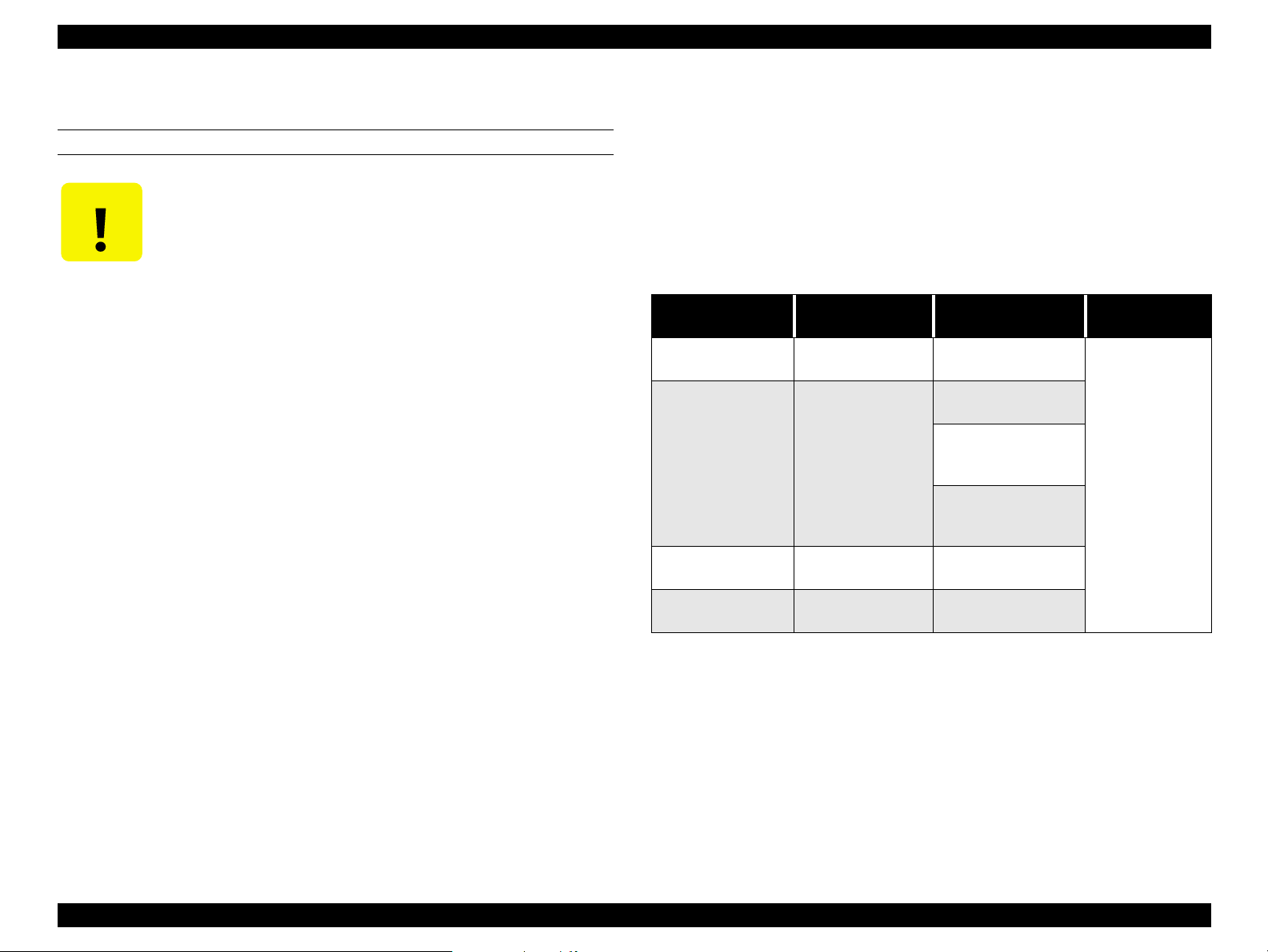
DANGER
WARNING
The precautionary measures itemized below should always be observed when performing repair/maintenance procedures.
Signals a precaution which, if ignored, could result in serious or fatal personal injury. Great caution should be
exercised in performing procedures preceded by DANGER Headings.
Signals a precaution which, if ignored, could result in damage to equipment.
DANGER
1. ALWAYS DISCONNECT THE PRODUCT FROM THE POWER SOURCE AND PERIPHERAL DEVICES PERFORMING ANY
MAINTENANCE OR REPAIR PROCEDURES.
2. NO WORK SHOULD BE PERFORMED ON THE UNIT BY PERSONS UNFAMILIAR WITH BASIC SAFETY MEASURES AS DICTATED
FOR ALL ELECTRONICS TECHNICIANS IN THEIR LINE OF WORK.
3. WHEN PERFORMING TESTING AS DICTATED WITHIN THIS MANUAL, DO NOT CONNECT THE UNIT TO A POWER SOURCE UNTIL
INSTRUCTED TO DO SO. WHEN THE POWER SUPPLY CABLE MUST BE CONNECTED, USE EXTREME CAUTION IN WORKING ON
POWER SUPPLY AND OTHER ELECTRONIC COMPONENTS.
WARNING
1. REPAIRS ON EPSON PRODUCT SHOULD BE PERFORMED ONLY BY AN EPSON CERTIFIED REPAIR TECHNICIAN.
2. MAKE CERTAIN THAT THE SOURCE VOLTAGES IS THE SAME AS THE RATED VOLTAGE, LISTED ON THE SERIAL NUMBER/
RATING PLATE. IF THE EPSON PRODUCT HAS A PRIMARY AC RATING DIFFERENT FROM AVAILABLE POWER SOURCE, DO NOT
CONNECT IT TO THE POWER SOURCE.
3. ALWAYS VERIFY THAT THE EPSON PRODUCT HAS BEEN DISCONNECTED FROM THE POWER SOURCE BEFORE REMOVING OR
REPLACING PRINTED CIRCUIT BOARDS AND/OR INDIVIDUAL CHIPS.
4. IN ORDER TO PROTECT SENSITIVE MICROPROCESSORS AND CIRCUITRY, USE STATIC DISCHARGE EQUIPMENT, SUCH AS ANTISTATIC WRIST STRAPS, WHEN ACCESSING INTERNAL COMPONENTS.
5. REPLACE MALFUNCTIONING COMPONENTS ONLY WITH THOSE COMPONENTS BY THE MANUFACTURE; INTRODUCTION OF
SECOND-SOURCE ICs OR OTHER NONAPPROVED COMPONENTS MAY DAMAGE THE PRODUCT AND VOID ANY APPLICABLE
EPSON WARRANTY.
Page 4

About This Manual
This manual describes basic functions, theory of electrical and
mechanical operations, maintenance and repair procedures of
EPSON EPSON Stylus PRO 7000. The instructions and procedures
included herein are intended for the experienced repair
technicians, and attention should be given to the precautions on
the preceding page.
Contents
This manual consists of six chapters and Appendix.
CHAPTER 1. PRODUCT DESCRIPTIONS
Provides a general overview and specifications of the product.
CHAPTER 2. OPERATING PRINCIPLES
Describes the theory of electrical and mechanical operations of the
product.
CHAPTER 3. TROUBLESHOOTING
Provides the step-by-step procedures for the troubleshooting.
CHAPTER 6. MAINTENANCE
Provides preventive maintenance procedures and the
lists of Epson-approved lubricants and adhesives
required for servicing the product.
CHAPTER 7. APPENDIX
Provides the following additional information for reference:
Connector pin assignments
Parts list
Electric circuit boards components layout
Exploded diagram
Electrical circuit boards schematics
CHAPTER 4. DISASSEMBLY AND ASSEMBLY
Describes the step-by-step procedures for disassembling and
assembling the product.
CHAPTER 5. ADJUSTMENTS
Provides Epson-approved methods for adjustment.
Page 5
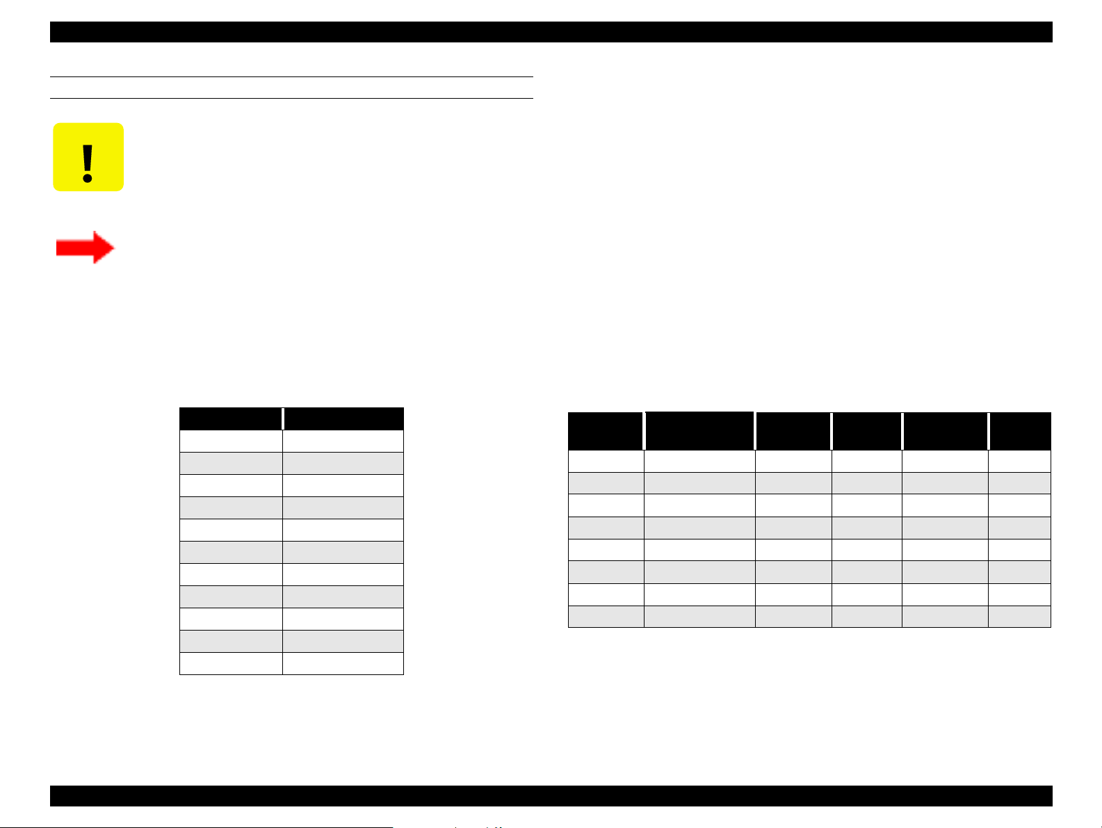
Symbols Used in This Manual
Various symbols are used throughout this manual either to provide
additional information on a specific topic or to warn of possible
danger present during a procedure or an action. Be aware of all
symbols when they are used, and always read WARNING,
CAUTION or NOTE messages.
Indicates a reassembly procedure, practice, or
condition that, if not strictly adhered to, could result
in damage to, or nonoperability of, the equipment.
W ARNING
CAUTION
CHECK
PO IN T
Indicates an operating or maintenance procedure,
practice or condition that, if not strictly observed, could
result in injury or loss of life.
Indicates an operating or maintenance procedure,
practice, or condition that, if not strictly observed,
could result in damage to, or destruction of,
equipment.
May indicate an operating or maintenance procedure,
practice or condition that is necessary to accomplish
a task efficiently. It may also provide additional
information that is related to a specific subject, or
comment on the results achieved through a previous
action.
Page 6

Revision Status
Revision Issued Date Description
Rev. A February 17, 2000 First Release
Rev. B April 12, 2000 Improved interface description (pg 31), nozzle check description (pg 43), paper thickness
detection (pg 46), cutter replacement (pg 47), maintenance mode 2 description (pg 50),
transportation mode (pg54)
Fixed illustrations on pages 60, 61, 63, 71
Fixed paper sensor volume adjustment
Added parts list and lubrication points
Added troubleshooting information regarding proper gap between cap and printhead
Added troubleshooting information regarding the cutter housing and encoder sensor
Page 7

EPSON Stylus Pro 7000 Revision B
Contents
Chapter 1 Product Description
Features
Interfaces
...................................................................................................... 12
Consumable Products & Options ........................................................ 13
Standard Accessories ......................................................................... 13
Print Specifications ............................................................................... 14
Printing Specifications........................................................................ 14
Character Specifications..................................................................... 14
Paper Feeding ..................................................................................... 14
Paper Specifications ............................................................................. 15
Roll Paper Specifications.................................................................... 15
Cut Sheet Specifications .................................................................... 16
Printable Area ....................................................................................... 17
Ink Cartridges ........................................................................................ 18
Electrical Specifications ....................................................................... 18
Reliability ............................................................................................... 19
Environmental Conditions ................................................................... 19
Temperature/Humidity ....................................................................... 19
Vibration & Shock ............................................................................... 20
Controller .............................................................................................. 20
Conformity/Safety Approvals .............................................................. 21
Acoustic Noise ...................................................................................... 21
CE Marking ............................................................................................ 22
.................................................................................................... 22
Parallel Interface - Compatibility Mode .............................................. 23
Data Transmission Timing ................................................................. 23
Parallel Interface - Nibble Mode .......................................................... 26
Parallel interface - ECP mode .............................................................. 27
USB ........................................................................................................ 29
TYPE-B Optional Interface ................................................................... 30
Preventing Data Transfer Time-Outs .................................................. 30
Interface Selection ................................................................................ 31
Physical Specifications
Printer Dimensions & Weight ............................................................ 32
Setup Guidelines ................................................................................ 32
Cutter Specifications .......................................................................... 33
Control Panel
Buttons ................................................................................................ 34
LED indicators ..................................................................................... 35
Indicator Status in Normal Mode ........................................................ 36
Control Panel Messages ...................................................................... 37
Panel Display Priority ........................................................................... 38
Loading Paper
SelecType Settings
Printer Setting Menu ............................................................................ 41
Test Print Menu .................................................................................... 42
Printer Status Menu ............................................................................. 44
Paper Configuration Settings .............................................................. 44
Cutter Replacement Menu ................................................................... 45
Head Alignment Menu ......................................................................... 46
Maintenance Request
Service Requests
Maintenance And Diagnostic Modes .................................................. 49
Maintenance Mode ............................................................................. 49
Maintenance Mode 2 .......................................................................... 50
Self-Diagnostic Mode ......................................................................... 51
Firmware Update
Jumper Settings
Initialization
Transportation Mode
............................................................................................. 34
............................................................................................ 39
........................................................................................ 52
............................................................................................... 52
............................................................................. 32
................................................................................... 40
............................................................................... 47
....................................................................................... 48
...................................................................................... 51
................................................................................ 53
7
Page 8

EPSON Stylus Pro 7000 Revision B
Chapter 2 Operating Principles
Component List & Illustrations
Print Mechanism Components ............................................................ 55
EPSON Stylus Pro 7000 Body & Stand ............................................. 57
Carriage Components......................................................................... 57
Paper Feed Path & Components........................................................ 58
Ink System Components .................................................................... 59
Electrical Circuit Boards ..................................................................... 59
Description of Components
Carriage Movement .............................................................................. 60
Carriage & Carriage Components ..................................................... 61
Paper Feed Assembly ........................................................................... 63
PF Rail .................................................................................................. 63
Paper-Feeding-Related Sensors ........................................................ 64
Maintenance Assembly ........................................................................ 65
CR Lock Mechanism ............................................................................. 66
Ink Supply Mechanism ......................................................................... 67
Ink-Related Sensors ............................................................................ 67
Printer Mechanism Operation Outline
Carriage Mechanism ............................................................................ 69
Platen Gap Mechanism ...................................................................... 70
Paper Feed Mechanism ...................................................................... 72
Summary of Control Circuit Operations
Power Supply Board Summary ........................................................... 78
................................................................ 55
...................................................................... 60
.................................................... 69
................................................. 76
Chapter 3 Troubleshooting
Outline
Troubleshooting Using the Error Messages
........................................................................................................ 80
First... ..................................................................................................... 80
Remember ............................................................................................. 80
Diagnosing the Problem ...................................................................... 80
Maintenance Errors .............................................................................. 81
Service Errors ....................................................................................... 82
........................................... 83
Warnings ............................................................................................. 85
Errors ................................................................................................... 86
Fatal Errors .......................................................................................... 92
Errors That Require a Service Technician
Maintenance Call 0100 ....................................................................... 93
Service Call 00000100 ......................................................................... 93
Service Call 00000101 ......................................................................... 93
Service Call 00010000 ......................................................................... 93
Service Call 00010001 ......................................................................... 94
Service Call 00010002 ......................................................................... 94
Service Call 00010003 ......................................................................... 94
Service Call 00010004 ......................................................................... 95
Service Call 00010005 ......................................................................... 95
Service Call 00010006 ......................................................................... 96
Service Call 00010007 ......................................................................... 96
Service Call 00010008 ......................................................................... 96
Service Call 00010009 ......................................................................... 97
Service Call 0001000A ........................................................................ 97
Service Call 0001000B ........................................................................ 97
Service Call 0001000C ........................................................................ 97
Service Call 0001000D
Service Call 0001000E ........................................................................ 97
Service Call 0001000F ......................................................................... 97
Service Call 00010010 ......................................................................... 97
Service Call 00020000 (NVRAM error)
Service Call 00020001 (Internal RAM error)
Service Call 00020002 (SRAM error)
Service Call 00020003 (DRAM error) ................................................. 98
Service Call 0002000B (Mail box Memory Error) ............................. 98
Service Call 10020004 (CPU gnrl illegal Instrctns)
Service Call 10020006 (CPU Slot illegal Instrctns)
Service Call 10020009 (CPU address error)
Service Call 1002000A (CPU DMAC/DTC address error)
Service Call 1002000B (CPU watchdog time-out error)
Service Call 100200## (CPU Vector 32~63) ....................................... 98
General Errors
Ink Low ................................................................................................ 99
Paper Out............................................................................................. 99
Load xxx Paper ................................................................................. 100
Load Paper ........................................................................................ 100
Paper Jam ......................................................................................... 100
Cover Open ....................................................................................... 100
Paper Not Cut .................................................................................... 101
............................................................................................ 99
............................................... 93
8
Page 9

EPSON Stylus Pro 7000 Revision B
Paper Not Straight ............................................................................ 101
Reload Paper ..................................................................................... 101
Please Lower Lever ........................................................................... 102
Ink Out................................................................................................ 102
No Ink Cartridge ................................................................................ 102
Remove Paper ................................................................................... 103
Option I/F Error.................................................................................. 103
Troubleshooting Based on Your Printout
Dot Missing ....................................................................................... 103
Uneven Printing/Poor Resolution .................................................... 104
Smudged or Marred Printout (Front) .............................................. 105
Smudged or Marred Printout (Reverse side).................................. 105
White or Black Banding .................................................................... 105
............................................. 103
Chapter 4 Disassembly & Assembly
Summary
Warnings ............................................................................................. 108
Tools .................................................................................................... 110
Screw List ............................................................................................ 111
Disassembly Flow
Removing the Housing ...................................................................... 113
Circuit Board Removal ....................................................................... 122
Printer Mechanism Disassembly ....................................................... 125
.................................................................................................. 107
.................................................................................... 112
Chapter 5 Adjustment
Adjustment Outline
Adjustment Tools ............................................................................... 157
Adjustment Items ............................................................................... 158
Adjustment Steps
Parameter Backup .............................................................................. 159
Requirements for parameter Backup .............................................. 159
Backing up parameters From Main Board to PC card ................... 160
Downloading Parameters From PC Card to new Board ................ 160
Backup/Download Error Recovery................................................... 161
Range of Backed Up Parameters ..................................................... 161
Firmware Update ................................................................................ 162
................................................................................. 157
.................................................................................... 159
Updating Firmware Via the PC ........................................................ 162
Updating Firmware From a Memory Card ..................................... 163
Self-Diagnostics
Self-Diagnostic Mode Menus
Test Menu ........................................................................................... 166
Version............................................................................................... 167
Control Panel..................................................................................... 167
Sensors .............................................................................................. 168
Sensor Adjustment ........................................................................... 169
Encoder.............................................................................................. 172
Fan ..................................................................................................... 172
Elec..................................................................................................... 172
D/A Revision and Head Signal ......................................................... 173
Adjustment Menu ............................................................................... 174
Adj Cap Position ............................................................................... 176
Adj Check Skew ................................................................................ 176
Write D/A Value................................................................................. 177
Adj Input Rank................................................................................... 177
Adj Check Nozzle .............................................................................. 178
Adj x Head Slant (B/C heads) ........................................................... 179
Adj B/C Head Height ......................................................................... 181
Adj Bi-D.............................................................................................. 183
Head Gap Adjustment ...................................................................... 187
Flush Point adjustment .................................................................... 188
Feed Adjustment............................................................................... 189
Adj Top & Bottom............................................................................. 190
Adj Rear Sensor Position ................................................................. 191
Test Pattern Print .............................................................................. 192
Clean Head (drain ink) ...................................................................... 193
Counter Clear .................................................................................... 194
Cleaning Menu ................................................................................... 194
Print Menu .......................................................................................... 195
Parameter Menu ................................................................................. 195
"Initialize" Items ................................................................................ 195
"Update" Items .................................................................................. 195
Mechanism Adjustment
CR Timing Belt Tension Adjustment ............................................... 198
PF Timing Belt Tension Adjustment................................................ 198
P THICK Sensor Assembly Adjustment .......................................... 199
....................................................................................... 164
................................................................. 165
......................................................................... 197
9
Page 10

EPSON Stylus Pro 7000 Revision B
Cover Open Sensor Assembly ......................................................... 200
USB ID Copy/Backup
Extracting the USB-ID Copy Program ............................................. 201
After Extracting the Program ........................................................... 201
Running the Program ......................................................................... 202
Copying the ID to the New Board.................................................... 202
Generating New ID & Writing It to the New Board ........................ 202
.............................................................................. 201
Chapter 6 Maintenance
General Maintenance Issues
Periodic Maintenance Items .............................................................. 206
Product Life Information .................................................................... 206
Important Maintenance Items During Service Operations ............. 207
Lubrication and Glue .......................................................................... 207
.................................................................. 204
Chapter 7 Appendix
Wiring Diagrams
Parts List
Exploded View Diagram
Component Layout
Circuit Diagrams
................................................................................................... 211
...................................................................................... 209
......................................................................... 215
.................................................................................. 226
...................................................................................... 228
10
Page 11

PRODUCT DESCRIPTION
CHAPTER
1
Page 12
EPSON Stylus Pro 7000 Revision B
1.1 Features
Paper Save feature searches for the front edge of the roll paper before
printing to make sure no paper at the leading edge is wasted
The EPSON Stylus Pro 7000 is an 24-inch wide, 6-color ink jet printer with
professional color output. It has the same printheads as the EPSON Stylus Pro
9000. The EPSON Stylus Pro 7000 provides the following major features and
more.
Large Format
A1, full size
24 inch-full size printing (A1+size supported)
Excellent Photo-quality printing
1440 (H) x 720 (V) dpi combined with EPSON’s Microdot printing
Same quality as the EPSON Stylus Pro 9000.
High-speed throughput
Table 1-1. Throughput Speed
EPSON media Slide Bar Resolution Dot Mode Speed
Plain Paper
Presentation
Matte Paper
Glossy Photo
Semigloss
Photo
Photo Quality
Glossy Film
Photo Quality
Ink Jet
Speed 360x360dpi Normal 2 Dot Bi-D 200cps 6 min.
Quality 360x360dpi Normal Dot x 2 Bi-D FOL 300cps 8 min.
Speed 720x360dpi Normal Dot Bi-D FOL 300cps 8 min.
Quality 720x360dpi Normal Dot Uni-D FOL 300cps 14 min.
Speed 720x360dpi Normal Dot Bi-D FOL 300cps 8 min.
Quality 720x720dpi Normal Dot Bi-D FOL 300cps 15 min.
Adv. Photo 1440x720dpi Micro Dot Bi-D 4P 300cps 30 min.
Quality 720x720dpi Micro Dot Bi-D FOL 300cps
Adv. Photo 1440x720dpi Micro Dot Bi-D 4P 300cps
Quality 720x720dpi Normal Dot Uni-D FOL 300cps
Adv. Photo 1440x720dpi Micro Dot Uni-D 4P 300cps
(Max.
A3+)
(Max.
A2)
Complete Software Compatibility With EPSON Stylus Pro 9000
Latest RIP Technology
CPSI Pro (software)
PS Server
Large format, yet provided as a desktop printer (optional stand
available)
Paper Handling:
Standard roll paper feeder
Straight paper path
Automatic paper cutter
Low running cost
Six separate ink cartridges so you only have to replace the empty ink
cartridge (each cartridge holds 110ml of ink)
Auto Rotate feature saves paper by automatically rotating an image if
the width is shorter than the height
Product Description Features 12
Page 13
EPSON Stylus Pro 7000 Revision B
1.1.1 Consumable Products & Options
Table 1-2. Consumables & Options
Name Code Product
Black Ink
Cyan Ink
Magenta Ink
Yellow Ink
Light Cyan Ink
Light Magenta Ink
Optional stand
Consumable item
For two-inch diameter roll paper
For three-inch diameter roll paper
610mm (24 in.) wide/20.7m long
24 in wide/25m long
24 in wide/25m long
A2
A3
A3 Wide/B
B
A3
A3 Wide/B
B
A3
A3 Wide/B
B
Fiery Adobe® PostScript® 3™
Server
Software RIP (CPSI Pro)
Ink cartridges
Stand
Paper cutter blade
Roll Feed Spindle 2”
Roll Feed Spindle 3”
Glossy Photo Paper
Semigloss Photo
Roll Paper
Presentation Matte
Roll Paper
Photo Quality Ink Jet
Paper
Photo Paper
Photo Quality Glossy
Film
Rip Station 5100 PS
Server Series II
Software RIP (CPSI
Pro)
T460
T463
T462
T461
T465
T464
C844022
C815131
C811092
C811102
S041225
S041223
S041220
S041079
S041068/S041045
S041069/S041043
S041070/S041044
S041142
S041143
S041156
S041073
S041074
S041075
EAI - C850092
Other - C850093
Table 1-2. Consumables & Options (continued)
Name Code Product
Multi-protocol
Ethernet interface
card
100Mbps Multiprotocol Ethernet
interface card
IEEE 1394 interface
card
Note:
* Signifies a number that varies by market.
C82362
C82363
C82372
Type-B 10Base-T
Type-B 100Base-T
IEEE 1394 interface card
STANDARD ACCESSORIES
The following are standard accessories with the SP 7000:
Power cord x1
Roll paper spindle (2”) x1
Ink cartridges x6, one for each color
Printer driver utility set x1
Roll paper sample x1 (24” semi-gloss Photo roll paper 5m)
Roll paper fixing belt x1
Paper cutter x1
User’s manual set x1
Product Description Features 13
Page 14
EPSON Stylus Pro 7000 Revision B
1.1.2 Print Specifications
PRINTING SPECIFICATIONS
Drop-
On-Demand MACH (Multi-layer Actuator Head) inkjet - E-MACH
type
Nozzle configuration
64 nozzles per color (same printhead as the EPSON Stylus Pro 9000)
Print direction = Bi-direction (high-speed return, high-speed skip only)
Print Speed and Printable Area
Character mode
Character pitch 10cpi (Pica)
Printable area 237 characters
Printing speed 200 cps (one print-pass in which 1/2 of character
matrix is printed at 360dpi: 2pass)
Graphic mode
Table 1-3. Print Area and Speed
Horizontal resolution
(dpi)
360
720
1440
Printable area Max. printable dots Speed
604mm
23.78 inches
604mm
23.78 inches
604mm
23.78 inches
8561
17,123
34,246
20 IPS
30 IPS/FOL
30 IPS/4pass
20 IPS/FOL
30 IPS/4pass
CHARACTER SPECIFICATIONS
Control codes
ESC/P Raster
EPSON Remote command
Character tables (2 international sets)
PC 437 (US, Standard Europe)
PC 850 (Multilingual)
Typeface
Bitmap LQ font: EPSON Courier 10 CPI
PAPER FEEDING
Paper feeding method: Friction feed
Line spacing: 1/6” or programmable at 1/720”
Paper path: Roll paper/manual
Feed speed: 1/6” 200
Continuous 2.5” (63.5mm)/second
10m seconds
±
Product Description Features 14
Page 15
EPSON Stylus Pro 7000 Revision B
1.1.3 Paper Specifications
ROLL PAPER SPECIFICATIONS
CAUTION
Minimum-Quality Roll Paper
Paper meeting the requirements described below can be used with this
printer, but neither the feeding nor printout quality is guaranteed.
•Size = Width 210~610mm
•Roll Size = 2” or 3” core (with opt ional 3” spindle) 150mm ext. diameter
max.
•Thickness = 0.08~0.5mm (0.003~0.019”)
Normal-Quality Roll Paper
For paper meeting the following requirements, the feeding operation only
is guaranteed.
•Size = Width 210~610mm
•Roll Size = 2” or 3” core (with opt ional 3” spindle) 150mm ext. diameter
max.
Paper must have no wrinkles, tears, or folds plus the surface
should be smooth.
(8.4~24.0”)
Length 279mm~90m (within roll size)
(11.1”~298.8’)
(8.4~24.0”)
Length 279mm~90m (within roll size)
(11.1”~30’)
paper from the core
*3: At the point where the rear edge comes free from the core (approx.
last 30 cm.), print quality is no longer guaranteed.
*4: If a 3” core is used, the EPSON-exclusive optional 3” roll paper spindle
is required
EPSON Special Roll Paper
The following special papers meet or exceed EPSON requirements, and
paper feeding plus printout quality are assured.
Table 1-4. EPSON Special Paper
Type (US) Type (outside US)
Presentation Matte
Paper
Glossy Paper-Heavy
Weight
Semi Glossy Paper-
Heavy Weight
Photo quality glossy
Film (TBD)
Presentation Matte
Paper
Glossy Photo Paper
Semigloss Photo
Paper
Photo quality
glossy Film (TBD)
*1: Use at normal room temperature (15~25°C (59~77°F) 40~60%
humidity)
*2: At the point where the rear edge comes free from the core (approx.
last 30 cm.), print quality is no longer guaranteed.
Paper Size
(W x H)
610mm x 25m
(24” x 83’)
610mm x 20.7m
(24” x 68.7’)
210mm (same as A4)
x 10m
(8.4” x 33.2’)
329mm (same as
A3+) x 10m
(13.1” x 33.2’)
610mm x 25m
(24” x 83’)
610mm x TBD
(24” x TBD)
Roll Size
2” core,
maximum103mm
external diameter
•Thickness = 0.08~0.11mm (0.003~0.0043”)
•Weight = 64~90gf/m
2
(17~24 lb.s)
•Quality = Normal paper, recycled paper
*1: Use at normal room temperature (15~25°C (59~77°F) 40~60%
humidity)
*2: The printer exerts between 300~500gf to peel off the rear edge of roll
Product Description Features 15
Page 16
EPSON Stylus Pro 7000 Revision B
CUT SHEET SPECIFICATIONS
CAUTION
Minimum-quality paper
Paper meeting the requirements described below can be used with this
printer, but neither the feeding nor printout quality is guaranteed.
Size = see the following table
Paper must have no wrinkles, tears, or folds plus the surface
should be smooth
Paper must be fed short-edge first (portrait)
Use at normal room temperature (15~25°C (59~77°F)
40~60% humidity)
Plain paper
For paper meeting the following requirements, only the feeding operation
is guaranteed.
•Size = see Table 1-5 above (plus the following requirements)
•Thickness = 0.08~0.11mm (0.003~0.0044”)
•Weight = 64~90gf/m
2
(17~24 lb.s)
•Quality: Normal, recycled paper
*1: Load short edge first (portrait)
*2: Use at normal room temperature (15~25°C (59~77°F) 40~60%
humidity)
EPSON Special Paper
The following special papers meet or exceed EPSON requirements, and
paper feeding plus printout quality are assured.
•Size = see the following table
Table 1-5. Supported Cut-Sheet Paper
Size Dimensions (W x H)
B2 515 x 728mm
A1+ 24 x 36”
A1 594 x 841mm
A2 420 x 594mm
A3+ 329 x 483mm
A3 297 x 420mm
A4 210 x 297mm
ANSI D 22 x 34”
ANSI C 17 x 22”
ANSI B 11 x 17”
Letter 8.5 x 11”
Size
A4 210 x 297mm Yes Yes Yes -
A3 297 x 420mm Yes Yes Yes -
A3+ 329 x 483mm Yes Yes Yes -
A2 420 x 594mm Yes - - -
Letter 216 x 279mm Yes Yes Yes -
B 279 x 432mm Yes Yes Yes -
C 431 x 558mm Yes - - -
B2 515 x 728mm - - - Yes
Table note:
*1: Print quality optimized with uni-direction printing
Table 1-6. Cut-Sheet Availability
Dimensions
(W x H)
SuperFine
*1
PhotoPrint
Photo Quality
Glossy Film
Art
Board
Thickness = 0.08~1.5mm (for 297~728mm/ 11.8~29.0” length paper
(0.003~0.06”)
0.08~0.5mm (for 728~915mm/ 29.0~36.4” length paper)
(0.003~0.02”)
Product Description Features 16
Page 17
EPSON Stylus Pro 7000 Revision B
1.1.4 Printable Area
LM
Paper
Feed
PW
Printable Area
TM
BM
RM
PL
Table 1-7. Printable Area
Heading Roll Paper Cut Sheets
PW (width)
PL (length)
LM (left margin)
TM (top) 3mm/15mm* 3mm
RM (right) 3mm/15mm* 3mm
BM (bottom) 3mm/15mm* 14mm
Note: *The size of the margin is determined by the control panel setting.
210 ~ 610mm
(8.27 ~ 24”)
Max. 90m
(298.8’)
3mm/15mm*
(0.12~0.59”)
210 ~ 610mm
(8.27 ~ 24”)
297~915mm
(11.8~36.4”)
3mm
There are three margin settings via the control panel;
3mm = All margins are set to 3mm
15mm = All margins are set to 15mm
T/B 15mm TM and BM are 15mm, while LM and RM are
3mm
Table 1-8. Optimal Margin Settings
To optimize for Select this setting
largest printable area and decrease chance of paper
rubbing printheads
exact paper size and decrease chance of paper rubbing
printheads
largest printable area and exact paper size 3mm
Top/Bottom 15mm
15mm
When the Paper Set Lever is:
Figure 1-1. Printable Area
Back
The feed path is open and you can load, remove or change the
position of paper in the feed path.
Forward
The feed path is closed and loaded paper is locked in place. You can
print on the loaded paper.
(It is not possible to change the lever position during printing.)
Product Description Features 17
Page 18
EPSON Stylus Pro 7000 Revision B
1.1.5 Ink Cartridges
Shape: Each ink cartridge is uniquely shaped so the
cartridges do not fit in the wrong slots.
Ink colors: Black, Cyan, Magenta, Yellow, Light Cyan, Light
Magenta
Ink life: Two years from production date
Ink volume: 110ml
Weight: 200g
Effective ink: 83.0g
Print capacity: A1 = approx. 28 pages at 720dpi and 40% coverage
A1 = approx. 11 pages at 720dpi and 100% coverage
D = approx. 26 pages at 720dpi and 40% coverage
A4 = approx. 3,800 pages at 360dpi and 5%
coverage
Dimensions: 25.1 x 141.1 x 105.3mm (WxDxH)
Weight: Approx. 200g
Storage temperature: See the table below
.
Table 1-9. Ink Cartridge Specifications
Situation Temperature Notes
Transporting
Storage
Installed
-30~50°C
(-22~122°F)
-20~40°C
(-7.6~104°F)
-30~40°C
(-22~104°F)
• Less than a month at 40°C (104°F)
• Less than 120 hours at 50°C (122°F)
Less than a month at 40°C (104°F)
Less than a month at 40°C (104°F)
1.1.6 Electrical Specifications
Table 1-10. Electrical Specifications
120V Model 220-240V Model
Rated voltage range
Input voltage range
Rated frequency range
Input frequency range
Rated current
Power consumption
Insulation resistance
Dielectric strength
10MΩ minimum (between AC line and chassis, DC 500 V)
AC 1,000V rms per minute
second (between AC line
AC120V AC220~240V
AC90~132V AC198~264V
1.0A (Max. 1.6A) 0.5A (Max.0.8A)
standby mode = 15W or less
Energy Star Compliant
or AC 1,200V rms per
and chassis)
50~60Hz
49.5~60.5Hz
AC 1,500V rms per minute
(between AC line and
chassis)
Do not refill or reuse cartridges; they are consumable items.
Do not use ink that beyond its expiration date. See above.
To use ink that has been frozen below -15 °C (5 °F), let it
thaw at least 3 hours at room temperature.
Product Description Features 18
Page 19
EPSON Stylus Pro 7000 Revision B
1.1.7 Reliability
Total print volume: 20,000 pages at A1 size
Printheads: 2,000,000,000 dots/nozzle
Cutter: Approximately 2,000 sheets (A1)
Maintenance parts: Approximately 12,000 sheets
Ink pad, Pump unit, Flushing box, Cap assembly,
and Head Cleaner are all included in the SP-7000
Maintenance Kit (P/N 1054038)
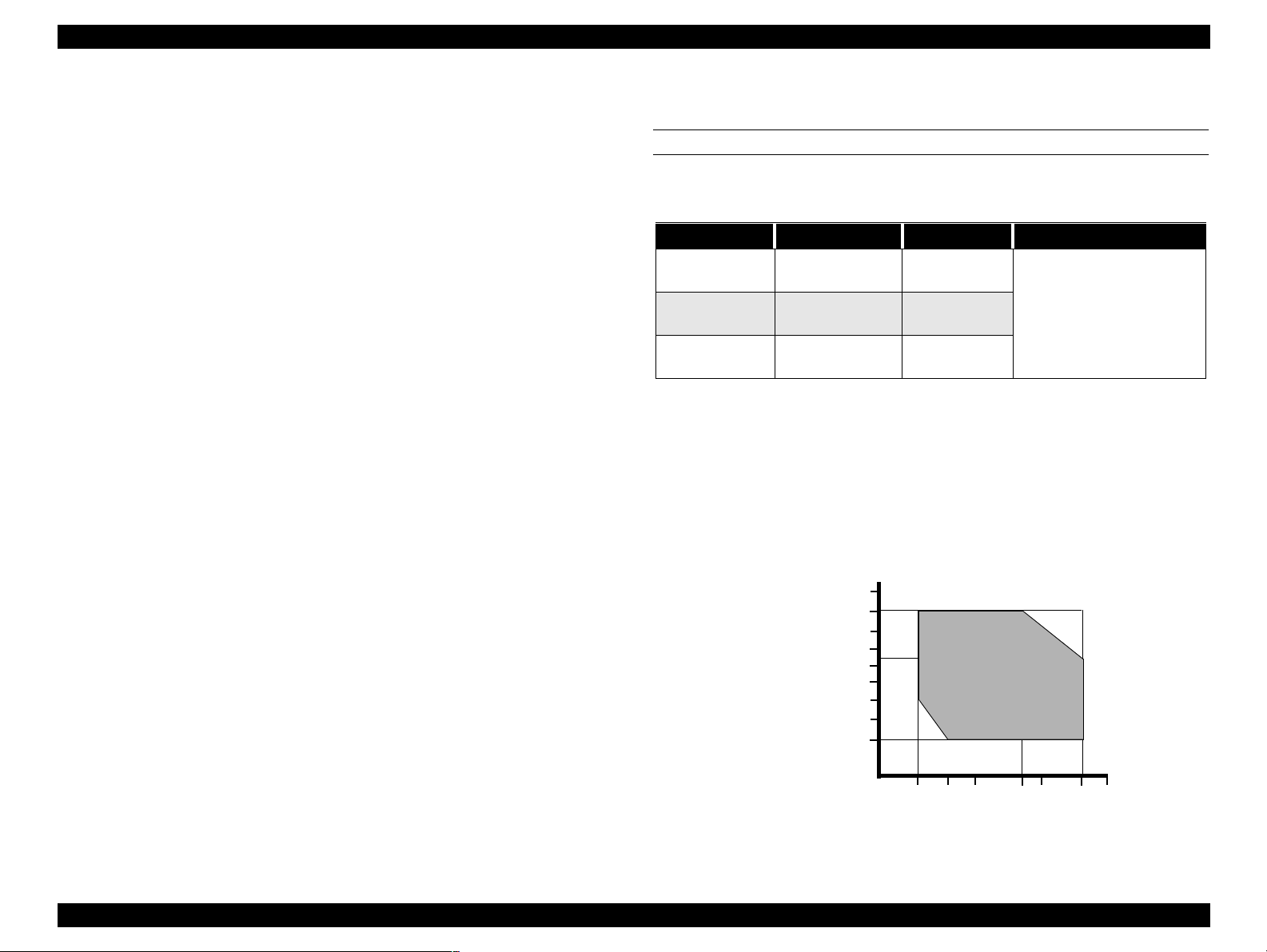
1.1.8 Environmental Conditions
TEMPERATURE/HUMIDITY
See the following table.
Table 1-11. Environmental Conditions
Condition Temperature Humidity Notes
Operating
Storage
Transportation
Notes:
1) When storing the printer, make sure the printheads are in the home (capped)
position. If necessary switch power on, wait for the printheads to move to the
home position, and then switch power off.
2) Before transporting the printer, remove the ink cartridges and turn the ink
valves screws to the closed position. Also make sure the printheads are in the
home, capped, position. After transporting the printer, install new ink
cartridges.
3) If the temperature drops below -15°C (5°F), the ink in the cartridges and
printheads freezes. The ink thaws completely after three hours at 25°C (77°F).
10~35°C
(50~95°F)
-20~40°C
(-4~104°F)
-20~60°C
(-4~140°F)
20~80%
20~85%
5-85%
• Less than a month at
40°C (104°F)
• Less than 120 hours at
60°C (140°F)
• With no freezing
90
80
70
60
Humidity (%)
50
40
30
20
10
10
15
20
27 30 35 40
Temperature (°C)
Figure 1-2. Print Temperature and Humidity
Product Description Features 19
Page 20
EPSON Stylus Pro 7000 Revision B
VIBRATION & SHOCK
See the following table.
Table 1-12. Vibration and Shock
Condition
Operating
Storage
Notes:
* Make sure the printhead is capped during transportation and storage. To cap
the printhead, turn the power on (with ink cartridges installed) and turn the
power off when the printheads are capped.
* To thaw frozen ink in the printer or cartridge, leave the printer out at a
temperature of 25°C (77°F) for approximately three hours.
Vibration
Resistance
0.15G
10~55Hz
0.5G
10~55Hz
Shock
Resistance
1G
maximum 1ms
2G
maximum 2ms
Notes
X/Y/Z directions
1.1.9 Controller
CPU: Hitachi SH7043, 33Mhz
RAM: 8MB + 2MB (fixed)
Interfaces: IEEE1284
USB
Type B (one expansion port)
Product Description Features 20
Page 21

EPSON Stylus Pro 7000 Revision B
1.1.10 Conformity/Safety Approvals
120V Model
Safety Standards:
UL1950
CSA 22.2 No. 950
EMI:
FCC part 15 subpart B class B
CSA C108.8 class B
220~240V Model
Safety Standards:
EN 60950
EMI:
EN55022 (CISPR Pub. 22) class B
AS/NZS 3548 class B
1.1.11 Acoustic Noise
Approx. 50dB(A) (According to ISO 7779)
Product Description Features 21
Page 22

EPSON Stylus Pro 7000 Revision B
1.1.12 CE Marking
220~240V Model
Low Voltage Directive 73/23/EEC: EN60950
EMC Directive 89/336/EEC EN55022 Class B
EN61000-3-2
EN61000-3-3
EN50082-1
IEC801-2
IEC801-3
IEC801-4
1.2 Interfaces
The EPSON Stylus Pro 7000 is equipped with parallel and USB interfaces as
well as an expansion slot for an optional Type-B interface. This section
provides information on each of these interfaces.
Product Description Interfaces 22
Page 23
EPSON Stylus Pro 7000 Revision B
1.2.1 Parallel Interface - Compatibility Mode
Table 1-13. Parallel Interface Specifications
Item Description
Transmission mode 8-bit parallel, IEEE-1284 compatibility mode
Synchronization By STROBE pulse
Handshaking By BUSY and ACKNLG signal
Logic Level
Connector
Note:
Use a twisted-pair cable that is as short as possible.
The BUSY signal is set high before setting the -ERROR signal low or the PE
signal high. The BUSY signal remains high until all these signals return to
their normal, inactive state.
The BUSY signal is high:
When receiving data
When the input data buffer is full
When the -INIT signal is low, or during hardware initialization
During a printer error
When the parallel interface is not selected
TTL compatible level (IEEE-1284 Level 1 device)
57-30360 (Amphenol) or equivalent
The ERROR signal is low when there is a:
Printer hardware error (fatal error)
Paper-out error
Paper-jam error
Ink-out error
NOTE: The PE signal is high during paper-out errors.
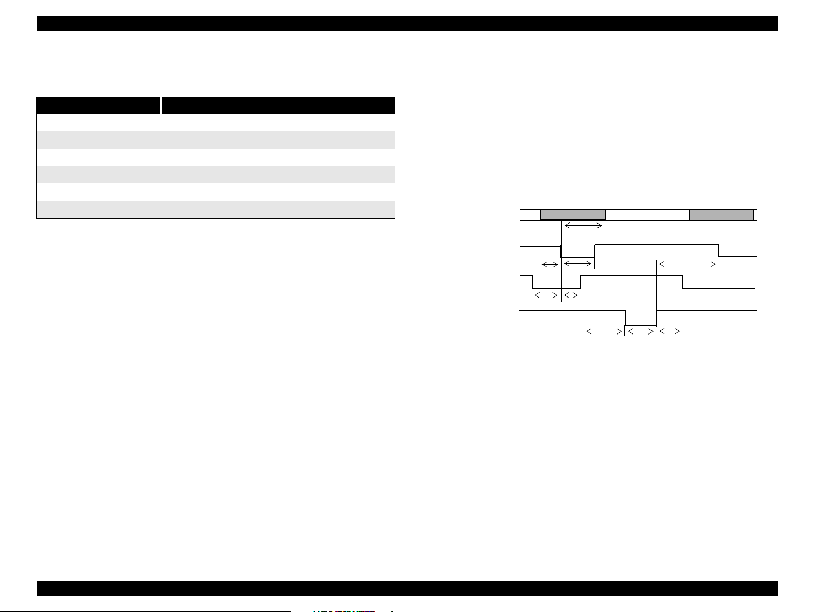
DATA TRANSMISSION TIMING
DATA
-STROBE
BUSY
-ACKNLG
ready
t
setup
t
data byte n
hold
t
t
busy
t
stb
t
reply
ack
t
nbusy
t
Figure 1-3. Data Transmission Timing
data byte n + 1
next
t
Product Description Interfaces 23
Page 24
EPSON Stylus Pro 7000 Revision B
Table 1-14. Data transmission times
Parameter Minimum Maximum
tsetup 500 ns -
thold 500 ns -
tstb 500 ns -
tready 0 -
tbusy - 500 ns
tt-out* - 120 ns
tt-in** - 200 ns
treply 0 -
tack Typical 2 us
tnbusy 0 -
tnext 0 -
* Rise and fall time of every output signal
** Rise and fall time of every input signal
Table 1-15. Typical tack time
Parallel I/F mode Time required
High speed (default) 0.5us
Normal speed 2us
Product Description Interfaces 24
Page 25
EPSON Stylus Pro 7000 Revision B
Table 1-16. Connector Pin Assignments and signals - Forward
Channel
Pin
No.
2-9
10
11
12
13
14
15
16
17
18
19-30
31
Signal
Name
-STROBE
1
DATA0~7
-ACKNLG
BUSY
PE
SLCT
-AFXT
NC
GND Ground for twisted pair return
Chassis
GND
Logic H Pulled up to +5V via 3.9Kohm
GND Ground for twisted pair return
-INIT
Return
Pin
19 I
20-27 I
28 O
29 O
28 O
28 O
30 I
- -
30 I
In/
Out
Data reception pulse. Data is read at the falling
edge of this pules.
The DATA0 through DATA7 signals represent
data bits 0 to7, respectively. Each signal is at
high level when data is logical 1 and low level
when data is logical 0.
This signal is a negative pulse indicating that
the printer can again accept data.
HIGH means the printer cannot receive data.
This occurs when the printer is receiving data
or when the printer is in an error state.
HIGH means no paper is loaded.
Always HIGH when the printer is on.
Not used
Not connected
Ground for frame/body
Pulse width of 50uS or more means LOW
pulse, and the falling edge of LOW signal
causes the printer to initialize.
Functional Description
Table 1-16. Connector Pin Assignments and signals - Forward
Channel (continued)
Pin
No.
34
35
36
Note: In (I) and Out (O) refer to the direction of signal flow from the printer’s point
NC
+5V
-SLIN
of view.
Signal
Name
Return
Pin
---- ----
---- O
30 I
In/
Out
Not connected
HIGH during normal operation. Pulled up to
+5V via 1.0Kohm
Not used
Functional Description
32
33
-ERROR
GND
29 O
---- ----
LOW means printer error
Ground for twisted pair return
Product Description Interfaces 25
Page 26
EPSON Stylus Pro 7000 Revision B
1.2.2 Parallel Interface - Nibble Mode
Table 1-17. Transmission Specifications
Description
Transmission mode IEEE-1284 nibble mode
Synchronization Refer to IEEE-1284 specification
Handshaking Refer to IEEE-1284 specification
Signal level TTL compatible (IEEE-1284 level 1 device)
Adaptable
connector
Data trans. timing Refer to IEEE-1284 specification
Extensibility request
Device ID
57-30360 (Amphenol) or equivalent
The printer responds affirmatively when the extensibility
request values are 00H or 04H:
00H: Request Nibble Mode Reverse Channel Transfer
04H: Request Device ID;
Return Data Using Nibble Mode Reverse Channel
Transfer
The printer returns the following strings when the device ID
is requested:
<00H><4EH>
MFG: EPSON
CMD: ESCPL2, BDC
MDL: Stylus[SP]Pro[SP]7000
CLS: PRINTER
DES: EPSON[SP]Stylus[SP]Pro{SP]7000
Note:
[00H] denotes a hexadecimal value of zero
MDL values depend on the EEPROM setting
Table 1-18. Connector Pin Assignments - Reverse Channel
Pin
Signal Name
No.
HostClk
1
Data0-7
2-9
PtrClk
10
PtrBusy/
11
DataBit-3,7
AckDataReq/
12
DataBit-2,6
Xflag/
13
DataBit-1,5
HostBusy
14
NC Not connected
15
GND Signal ground
16
Chassis GND Chassis ground
17
Logic-H
18
19-30
Note: In (I) and Out (O) refer to the direction of signal flow from the printer’s point
GND Ground for twisted pair return
-INIT
31
-DataAvail/
32
DataBit-0,4
GND Signal ground
33
NC Not connected
34
+5V
35
1284-Active
36
of view.
Return
Pin
19 I
20-27 I
28 O
29 O
28 O
28 O
30 I
30 I
29 O
---- O
30 I
In/
Out
Host clock signal.
The DATA0 through DATA7 signals
represent data bits 0 to7, respectively.
Each signal is at high level when data is
logical 1 and low level when data is logical
0.
Printer clock signal
Printer busy signal and reverse channel
transfer data bit 3 or 7.
Acknowledge data request signal and
reverse channel transfer data bit 2 or 6.
X-flag signal and reverse channel transfer
data bit 1 or 5.
Host busy signal.
Pulled up to +5V via 3.9K ohm resister.
O
Not used.
Data available signal and reverse channel
transfer data bit 0 or 4.
Pulled up to +5V via 1.0K ohm resister.
1284 Active Signal
Functional Description
Product Description Interfaces 26
Page 27
EPSON Stylus Pro 7000 Revision B
1.2.3 Parallel interface - ECP mode
Table 1-19. Transmission Specifications
Description
Transmission mode IEEE-1284 ECP mode
Synchronization Refer to IEEE-1284 specification
Handshaking Refer to IEEE-1284 specification
Signal level IEEE-1284 level 1 device
Adaptable
connector
Data trans. timing Refer to IEEE-1284 specification
Extensibility request
Device ID
See forward channel
The printer responds affirmatively when the extensibility
request values are 10H or 14H:
10H: Request ECP Mode Reverse Channel Transfer
14H: Request Device ID;
Return Data Using ECP Mode Reverse Channel
Transfer
The printer returns the following strings when the device ID
is requested:
<00H><4EH>
MFG: EPSON
CMD: ESCPL2, BDC
MDL: Stylus[SP]Pro[SP]7000
CLS: PRINTER
DES: EPSON[SP]Stylus[SP]Pro{SP]7000
Note:
[00H] denotes a hexadecimal value of zero
MDL values depend on the EEPROM setting
Product Description Interfaces 27
Page 28
EPSON Stylus Pro 7000 Revision B
Table 1-20. Connector Pin Assignments - ECP Mode
Pin
No.
1
2-9
10
11
12
Signal Name
HostClk
Data0-7
PeriphClk
PeriphAck
nAckReverse
Return
Pin
19 I
20-27 I
28 O
29 O
28 O
In/
Out
Data or address information is transferred
from the host to the printer.
The DATA0 through DATA7 signals
represent data bits 0 to7, respectively.
Each signal is at high level when data is
logical 1 and low level when data is logical
0. These signals are used to transfer the
1284 extensibility request values to the
printer.
Data is transferred from the printer to the
host.
The printer uses this signal for flow
control in the forward direction. Also used
for data bit 9 which indicates command
information and data to be output on the
data signal in the forward direction.
The printer goes to Low and approves the
nReverseRequest.Acknowledge data
request signal and reverse channel
transfer data bit 2 or 6.
Functional Description
Table 1-20. Connector Pin Assignments - ECP Mode
Pin
Signal Name
No.
nReverseReq
31
uest
nPeriphRequ
32
est
GND Ground for twisted pair return
33
NC Not connected
34
+5V
35
1284-Active
36
Note: In (I) and Out (O) refer to the direction of signal flow from the printer’s point
of view.
Return
Pin
30 I
29 O
---- O
30 I
In/
Out
This signal goes low to change to the
reverse channel.
This signal produces a host interrupt.
Always HIGH. Pulled up to +5V via 1.0K
ohm resister.
1284 Active Signal. HIGH in ECP mode
Functional Description
13
14
15
16
17
18
19-30
Xflag
HostAck
NC Not connected
GND Signal ground
Chassis GND Chassis ground
PeriphLogicH
GND Ground for twisted pair return
28 O
30 I
X-flag signal and reverse channel transfer
data bit 1 or 5.
The host uses this signal for flow control
in the reverse direction. Also used for data
bit 9 which indicates command
information and data to be output on the
data signal in the forward directions.
Always HIGH. Pulled up to +5V via 3.9K
O
ohm resister.
Product Description Interfaces 28
Page 29
EPSON Stylus Pro 7000 Revision B
1.2.4 USB
Standard :“Universal Serial Bus Specifications Revision 1.0”
“Universal Serial Bus Device Class Definition for
Printing Devices Version 1.0”
Bit rate :12Mbps (Full speed device)
Data encoding :NRZI
Adaptable connector :USB series B
Suggested cable length :2 meters
Table 1-21. USB connector pin assignments and signals
Pin no. Signal name In/Out Description
1 VCC -
2 -Data bi-directional
3 +Data bi-directional
4 Ground -
Pin #2
Cable power, max. power consumption is
100mA
data
data, pull up to +3.3V via 1.5K Ω resistor
Cable ground
Pin #1
Device ID
<00H><4EH>
MFG: EPSON
CMD: ESCPL2, BDC
MDL: Stylus[SP]Pro[SP]7000
CLS: PRINTER
DES: EPSON[SP]Stylus[SP]Pro{SP]7000
NOTE: To use USB interface: set “PARA.I/F=COMPAT.” in the Printer
Settings Menu.
Pin #3
Pin #4
Figure 1-4. USB Pins
Product Description Interfaces 29
Page 30

EPSON Stylus Pro 7000 Revision B
1.2.5 TYPE-B Optional Interface
The EPSON Stylus Pro 7000 supports a Type-B interface (level 2).
Reply message (short version):
When using a Co-ax/Twin-ax interface card:
Main type: MTP48p, PW127cl10cpi, PRG (B0xxxx)rev,
AP1200ma
Product name: Stylus[SP]Pro[SP]7000
Emulation type: ESCPL2-00
Entity type: EPSONLQ2
When using a card other than a Co-ax/Twin-ax interface card:
Main type: MTP48p, PW127cl10cpi, PRG (B0xxx)rev,
AP1200ma, SPD0fast
Product name: Stylus[SP]Pro[SP]7000
Emulation type:ESCPL2-00
Entity type: ESPONLQ2
1.2.6 Preventing Data Transfer Time-Outs
Generally, hosts abandon data transfer to peripherals when a peripheral is in
the busy state for dozens of seconds continuously. To prevent hosts from
entering this kind of time-out period, the printer slows down the data
reception rate to about one byte per second when there is less than 4kb of
free space in the printer buffer. Data reception comes to a complete stop if the
free space is less than 32 bytes, but returns to one byte per second when free
space reaches 1KB or more.
Product Description Interfaces 30
Page 31

EPSON Stylus Pro 7000 Revision B
1.2.7 Interface Selection
The SP 7000 has one slot for an optional Type-B interface and two built-in
interfaces; the USB and parallel interfaces.
The printer has only two internal BUS lines for the interfaces, so the parallel
and USB interfaces share one line while the other line is exclusive to the
Type-B interface. The USB interface takes priority when both interfaces are
connected meaning the USB interface works but the parallel does not. Make
sure nothing is connected to the USB interface before printing via the parallel
interface.
Interface status and selection
When the option interface is selected, the parallel/USB interface goes into
the busy state. The LH signal is “L” at this time. “L” means the power is
cut, in other words 1284 does not respond. Therefore, the LH check is
required via the Reverse channel. The USB interface responds NACK and
cannot receive data.
The the option interface is not selected, an off-line bit is set to Main Status
Register (MNSTS). When the printer initializes or returns to the idle state,
the USB interface is out of the NACK condition and resets the off-line bit
of the Main Status Register to option interface.
The parallel or USB interface can operate normally even if an optional Type-B
interface is installed and connected. The interface in use can be selected
automatically or manually.
Manual selection
The interface can be manually determined using the Printer Setting
Menu; see SelecType in the user’s guide for details.
The choices are INTERFACE = PARA/USB or INTERFACE = OPTION.
Automatic selection
If the interface setting is set to “AUTO” (default), the printer scans the
interfaces for incoming data. The interface that receives data first is
selected.
As long as the host sends data or the printer interface is in the busy state,
the interface selection does not change.
When the host stops transferring data and the printer is in the stand-by
state for a certain period of time, the printer returns to the idle state.
Be aware that an interrupt signal such as the -INIT signal only takes effect
on the parallel interface when the parallel interface is selected.
When the printer is initialized or returns to an idle state, the parallel
interface enters a ready condition, the serial DTR signal is set to low, and
the off-line bit of the Main Status Register (MNSTS) is reset.
The /INIT signal on the parallel interface is not active while that interface
is in Nibble or ECP Mode, or is not selected.
Product Description Interfaces 31
Page 32

EPSON Stylus Pro 7000 Revision B
1.3 PHYSICAL SPECIFICATIONS
PRINTER DIMENSIONS & WEIGHT
Dimensions: 1100 x 572 x 560mm (WxDxH)
(43.8 x 22.8 x 22.3 inches)
Weight: 43.5Kg (95.7 lb.s)
SETUP GUIDELINES
When setting up the printer on a desk or table top, refer to the instruction and
illustration below. (When setting up the printer using the optional stand, see
the setup guide that comes with the stand for details.)
1. Make sure the printer is 60~80cm (24~32”) off the floor.
2. Make sure the nearest obstruction in front of the printer is at least 60cm
(24”) away.
Nearest
obstruction
Paper eject
direction
At least 60cm
60~80cm
Figure 1-5. Printer Dimensions
Floor
Product Description Physical Specifications 32
Page 33

EPSON Stylus Pro 7000 Revision B
CUTTER SPECIFICATIONS
Attributes: Consumable item that is replaced by the user, and it
is made of very hard steel, so the blade can be
chipped. Handle carefully to avoid cuts to yourself
and to avoid chipping the blade.
Life: The cutter can cut well over 2,000 sheets of paper,
but the actual wear-and-tear depends on the type
and thickness of the paper used.
The cutter life can be determined manually; attempt
to cut a piece of normal paper and if the cutter easily
cuts the paper, it is OK.
Unlike the cutter position with the EPSON Stylus Pro
9000, the SP 7000 cutter position is automatically
determined by the carriage cover position. No
adjustment is needed for the cutter position or the
carriage cover height.
Product Description Physical Specifications 33
Page 34

EPSON Stylus Pro 7000 Revision B
1.4 Control Panel
This section describes the control panel, the buttons, the lights, and the way
you make settings.
Figure 1-6. Control Panel
BUTTONS
All eight buttons on the control panel and their functions are described below.
Table 1-22. Buttons and Functions
Button
(Second function)
Power Power on/off N/A N/A
Pause
(Reset)
SelecType
Cut/Eject
(Enter)
Paper Feed
Paper Feed
Paper Source
(Item)
Cleaning
Paper Source +
Cut/Eject +
Paper Feed
Paper Source +
Cut/Eject +
Cleaning
Notes:
1: Interrupts ink drying and runs the specified operation.
2: 1.27cm/second paper feed for 2 seconds after key is pressed. 7.62cm/second
paper feed if pressed for over two seconds. Maximum feed of 20cm with one
press of the button.
3: 1.27cm/second paper feed for 2 seconds after key is pressed. 7.62cm/second
paper feed if pressed for over two seconds.
• Switch -pause/ready
• Reset (press 3 seconds)
• Enters SelecType mode
• Opens Cutter
Selects *1
•Auto Cut
• Cutter Off
• Sheet
↑
Feeds paper backward *2
↓
Feeds paper forward *3
Cleans both heads (press
for three seconds)
↓
Function
(Normal)
Replacement Menu
(press for five seconds)
Selects paper source
N/A
SelecType
Function
N/A
Selects menu or
major category
Confirms and saves
setup values
Cycles backward/
increases value
Cycles forward/
decrease value
Selects item or
minor category
N/A
Power-On
Function
Maintenance
Mode
N/A
Maintenance
Mode 2
Firmware
Update
Mode
Product Description Control Panel 34
Page 35

EPSON Stylus Pro 7000 Revision B
LED INDICATORS
Table 1-23. LED Indicator Lights
LED Status Condition
•On
Operate
Paper Out
Pause
Ink Out Y
Ink Out LM
Ink Out LC
Ink Out M
Ink Out C
Ink Out K
Roll Auto Cut
Paper Type
(Cut Off)
Sheet
Note: *Also occurs if no cartridge is installed or the wrong cartridge is installed.
•Flashing
•On
•Flashing
•On
•Flashing
•On
•Flashing
•On
•Flashing
•On
•Flashing
•On
•Flashing
•On
•Flashing
•On
•Flashing
•On
•Flashing
•On
•Flashing
•On
•Flashing
• Power on
• Receiving data or performing power-down
sequence
• No paper loaded, end of roll, sheet/roll paper
error, paper set lever is in release position, or
the loaded paper is too thick for cleaning
• Paper jam, paper cutting, paper skew, or paper
check error
•Paused
• Performing head cleaning or the printer is in
ink drying phase. Also flashes during ink
charging operation.
• Ink out*
• Ink low
• Ink out*
• Ink low
• Ink out*
• Ink low
• Ink out*
• Ink low
• Ink out*
• Ink low
• Ink out*
• Ink low
• Auto cut selected
• Roll paper not set or roll paper and cut sheet
sizes are different
• Roll paper will not be cut
• Roll paper not set or roll paper and cut sheet
sizes are different
• Single sheet printing mode.
• Roll paper not set or roll paper and cut sheet
sizes are different
Product Description Control Panel 35
Page 36

EPSON Stylus Pro 7000 Revision B
1.4.1 Indicator Status in Normal Mode
Table 1-24. Operate Indicator
Printer Status Indicator
With power on and in any status other
than those listed below.
While processing data and during power
off sequence
Fatal error Flashing
Reset, timer IC reset/NVRAM clear On
Table 1-25. Paper Out Indicator
Printer Status Indicator
Out of paper, end of roll On
Roll paper and sheet sizes are different On
Paper set lever in release position On
Paper is too thick to perform cleaning On
Paper jam Flashing
Paper cutting error Flashing
Paper skew Flashing
Paper check error Flashing
Problem with paper eject (sheet) Flashing
Fatal error Flashing
Reset, timer IC reset/NVRAM clear On
Flashing
On
Table 1-26. Pause Indicator
Printer Status Indicator
Ready Off
In SelecType mode Off
Paused Off
Ink drying phase Flashing
Ink charging sequence Flashing
Other errors Off
Fatal error Flashing
Reset, timer IC reset/NVRAM clear On
Table 1-27. Ink Out Indicators
Printer Status Indicator
Out of specified ink
No I/C for specified ink
Wrong I/C for that slot
Ink low Flashing
Fatal error Flashing
Reset, timer IC reset/NVRAM clear On
On
Product Description Control Panel 36
Page 37

EPSON Stylus Pro 7000 Revision B
1.4.2 Control Panel Messages
Table 1-28. Paper Source Indicator
Printer Status Indicator
Selected paper source On
Fatal error Flashing
Roll paper and sheet sizes are different Flashing
Reset, timer IC reset/NVRAM clear On
Printer status and error messages appear on the control panel display. The
table below lists the messages.
Table 1-29. Control Panel Messages
Display Message Meaning
SERVICE REQ. nnnnnnnn
TURN PWR OFF AND ON
RESET
TRANSPORT PREP nn%
POWER OFF
COVER OPEN
SECURE PAPER LEVER
NO INK CARTRIDGE
OPTION I/F ERROR
INK OUT
Fatal error - see “Service Requests” on
page 48
Turn the printer off and on to reinitialize
In the process of re-initializing.
See “Transportation Mode” on page 53
Preparing to shut down.
The cover is open. The carriage stops in place,
and the printhead can be damaged if the head
remains out of the capped position for a long
period of time.
Paper Set lever is in the released and cannot
continue or begin a print, cleaning, or
initialization sequence.
One or more cartridges are not installed
An unsupported Type-B interface card is
installed.
• A predetermined amount of ink has been
consumed after the cartridge has entered
the near-end condition.
• A near-end cartridge has been removed and
re-installed.
Table 1-29. Control Panel Messages (continued)
Display Message Meaning
READY *
WAIT *
INK CHARGING nnn%
INK DRY xx MIN *
PRESS PAUSE BUTTON
LOAD xxx PAPER
LOAD PAPER
PAPER JAM
PAPER NOT CUT
PAPER NOT STRAIGHT
Can receive and print data.
Resetting Timer IC
Clearing NVRAM
Performing reset operation
Performing ink sequence operation
Initializing the printer
Initializing the paper
Initial charging of ink - shown in percent
completed
Printer waits xx minutes before the next print
job to allow enough time for ink to dry on
previous print job.
Waiting for paper initialize start trigger
Wrong paper loaded or wrong paper source
selected on control panel.
The Paper Set Lever is in the released position
(before printing). Pull the Paper Set lever
forward to the set position
Both front and rear paper sensors detect paper
and there is a carriage over-current or out of
step error. This is due to:
• Paper is jammed inside the printer
• Paper is obstructing the carriage path
during feeding or cutting operation.
Printer did not cut the paper completely, or the
cut piece still remains over the paper sensor
Paper skewed more than 3mm between the
leading and following edges. Check the
printout for skew and make sure no ink was
fired onto the platen.
Product Description Control Panel 37
Page 38

EPSON Stylus Pro 7000 Revision B
Table 1-29. Control Panel Messages (continued)
Display Message Meaning
When trying to print a test or adjustment
pattern, one of the following occurs:
UNABLE TO PRINT
RELOAD PAPER
REMOVE PAPER
PAUSE
INK LOW
MAINTENANCE REQ. nnnn
PRINTING *
PAPER OUT
Notes*: If the printer’s platen gap setting is set to Thick, a “H” will appear in the
last space on the LCD display.
• Paper not loaded
• Ink cartridge not loaded
• Paper detection error
• The paper was loaded too far forward and
cannot be backward fed to the proper
position.
• The paper’s horizontal position exceeds the
normal printable area when the paper is
loaded.
• The paper’s horizontal position exceeds the
normal cutting area after printing.
• The cut sheet is too long and cannot be
ejected properly.
• Recovery from cutter error.
Loaded paper is too thick to perform timer
cleaning
Pause state.
When total dots fired = 90%, cartridge enters
near-end condition. Remaining ink = A1 at
100% duty
Printer requires maintenance - see
“Maintenance Request” on page 47
Processing print data.
• No paper loaded
• End of roll paper (printer stops feeding)
• End of sheet paper (when paper feeds to
eject position, put hand under the sheet and
press Cut/Eject to release)
1.4.3 Panel Display Priority
High priority to low priority
Fatal errors/restart required
Reset, timer IC rest/NVRAM clear
Entering or in power-off sequence/transport preparation sequence
Entering or in ink-cartridge-replacement sequence
Cover open
Paper set lever released during operation
Type B interface error
No ink cartridge
Wrong ink cartridge
Ink out
Roll paper and sheet sizes are different
Paper jam
Paper set lever in release position
Paper cutting error
Paper not straight
Paper check error
Roll paper end
Paper eject error
Initializing
Paper is too thick for cleaning
Entering or in ink sequence
Waiting for paper-initialization trigger
Paused
Entering or in paper initialization
Entering or in ink drying time-out
Ink low/Maintenance required
Processing data/printer ready
Out of paper
Product Description Control Panel 38
Page 39

EPSON Stylus Pro 7000 Revision B
1.5 Loading Paper
To automatically cut off the printed roll paper after printing:
1. Push back the paper set lever to the release position. The printer is
incapable of printing.
2. Select Roll, Auto Cut using the Paper Source button.
3. Load the paper from the paper insertion slot and align it with the paper
guideline.
4. Pull the paper set lever forward to the set position.
5. If the surface of the paper is dirty or indented anywhere, use the Paper
Feed buttons to skip over that area. When that area passes the cut off line,
press the Cut/Eject button. This trims the unusable section of paper, and
the printer is now ready to print.
6. Push the Pause button or wait ten seconds to automatically feed the
paper back to the standby position. The printer is ready to receive print
data, print it, and cut off the paper.
To print and not cut off the roll paper:
1. Pull up the paper set lever to the release position. The printer is incapable
of printing.
To use cut sheets
smaller than A3+ size cut sheets
1. Select Sheet using the Paper Source button.
2. Make sure the paper set lever is in the forward (set) position, and load a
sheet in the paper insertion slot
3. Push the Paper Feed or Pause button (you need to press one) to feed the
paper forward to the standby position. The printer is ready to receive
print data.
A3+ or larger size cut sheets
1. Push back the paper set lever to the release position. The printer is
incapable of printing.
2. Select Sheet using the Paper Source button.
3. Load the paper from the paper insertion slot and align it with the paper
guideline.
4. Pull the paper set lever forward to the set position.
5. Push the Pause button or wait ten seconds to automatically feed the
paper forward to the standby position. The printer is ready to receive
print data.
2. Select Roll, Cutter Off using the Paper Source button.
3. Load the paper from the paper insertion slot and align it with the paper
guideline.
4. Pull the paper set lever forward to the set position.
5. If the surface of the paper is dirty or indented anywhere, use the Paper
Feed buttons to skip over that area. When that area passes the cut off line,
press the Cut/Eject button. This trims the unusable section of paper, and
the printer is now ready to print.
6. Push the Pause button or wait ten seconds to automatically feed the
paper forward to the standby position. The printer is ready to receive
print data and print.
Product Description Loading Paper 39
Page 40

EPSON Stylus Pro 7000 Revision B
1.6 SelecType Settings
Entering SelecType mode
To access the control panel settings, press the SelecType button while the
printer is not printing. The printer enters the SelecType mode and cannot
print.
Using SelecType mode
1. Repeatedly press the SelecType button to view the SelecType menus
which appear in the order shown below.
Table 1-30. SelecType Menus
Display Message For details, see
PRINTER SETTING MENU
TEST PRINT MENU
PRINTER STATUS MENU
PAPER CONFIG. MENU
CUTTER REPLACE MENU
HEAD ALIGNMENT MENU
2. Press the Item button to select the choice shown in the LCD display.
“Printer Setting Menu” on page 41
“Test Print Menu” on page 42
“Printer Status Menu” on page 44
“Paper Configuration Settings” on page 44
“Cutter Replacement Menu” on page 45
“Head Alignment Menu” on page 46
Exiting SelecType mode
Select one of the following methods to exit SelecType mode:
Press the Pause button while in SelecType mode; the printer is ready
to print.
Perform the printer initialization.
Print a status sheet.
Print a nozzle check pattern.
Replace the cutter.
Press the SelecType button several times at the top level of
SelecType menus.
Press the SelecType button one time at the second level of SelecType
menus.
3. Press the SelecType button to view the options for that Item.
4. Press the “+” button or “-” button to view the available values for an
option.
5. Press the Enter button to record the current option or to execute the
operation shown in the display.
Product Description SelecType Settings 40
Page 41

EPSON Stylus Pro 7000 Revision B
1.6.1 Printer Setting Menu
Table 1-31. Printer Setting Menu
Display Message Options Notes
PLATEN GAP
PAGE LINE
INTERFACE
PARA. I/F
CODE PAGE
ROLL MARG
Auto
Wide
ON
OFF
Auto
Para/USB
Option
Compat
ECP
PC437
PC850
T/B 15MM
15MM
3MM
Adjusts the platen gap. (Normally, leave
set to Auto.)
When Auto Cut Off is selected on the
control panel, this setting determines
whether a line for manual cutting is
printed.
Determines which interface the printer
checks for data. Auto continuously
checks all interfaces and is good for
normal use.
Determines the data transfer rate when
using this interface.(Normally, leave set
to Compatible.)
Character code setting. (PC437:
expanded graphics/PC850: multi-lingual)
Roll sheet margin setting.
• Top/Bottom 15mm*
top and bottom margins = 15mm
left and right margins = 3mm
• 15mm: all margins = 15mm
• 3mm all margins = 3mm
Platen gap
You can adjust the platen gap using this option. (See “Platen Gap
Mechanism” on page 70 for details.)
Roll paper margin
T/B 15MM = the printed image is the same size whether the margin is
15mm or 3mm. The difference is 12mm of paper clearance is added to the
top and bottom edges to make paper feeding more stable and to prevent
the paper from rubbing the printheads.
If the print area is greater than the width of the printable area of the
paper, the printer ignores the extra print data on the right side of the
paper.
Paper size check
You can disable the paper size check to prevent “RELOAD PAPER” errors
which may occur when using very thin paper or paper with low reflective
qualities such as tracing paper.
The print area is determined manually, and the printheads will fire ink
onto the platen if the print area is set larger than the actual paper size.
PAPER SIZE CHK
PAPER ALIGN CHK
INIT. PANEL Exec.
Notes:
* The printed image is the same size whether the margin is 15mm or 3mm. The
difference is 12mm of paper clearance is added to the top and bottom edges to
make paper feeding more stable and to prevent the paper from rubbing the
printheads.
The underlined item equals the default.
ON
OFF
ON
OFF
Determines whether the paper size check
is enabled
Determines whether the paper skew
check is enabled
Initializes control panel setup values to
their defaults
Product Description SelecType Settings 41
Page 42

EPSON Stylus Pro 7000 Revision B
1.6.2 Test Print Menu
Table 1-32. Test Print Menu
Display Message Item Notes
NOZZLE CHECK Print
STATUS SHEET Print
1.6.2.1 Nozzle check
Version: BO289C
Ink Pad: 94%
Note: the actual pattern prints in color: black, cyan,
magenta, light cyan, light magenta, and yellow
The firmware version is described as the date the firmware was set.
Check the printout, any missing lines
mean the nozzle(s) are clogged.
Prints the current printer settings.
1.6.2.2 Status sheet
BO = EPSON Stylus Pro 7000
28 = date
9 = last digit of year (1999 in this case)
C = month (16H, so 1 means January, A means October and C means
December)
The remaining capacity of the waste ink pads is shown as a percentage.
Head Gap = see Platen Gap in Printer Status Menu, page 44
Border Line = see Page Line in Printer Status Menu, page 44
Interface = See Table 1-31, “Printer Setting Menu,” on page 41
Parallel I/F = See Table 1-31, “Printer Setting Menu,” on page 41
Product Description SelecType Settings 42
Page 43

EPSON Stylus Pro 7000 Revision B
Code page = PC 437 (US/Europe) or PC 850
Version = Firmware version
Ink Left = see below
E***** F 100~81% remaining
E**** F 80~61% remaining
E*** F 60~41% remaining
E** F 40~20% remaining
E* F 20%~near end
nn% near end ~ ink end (Ink End LED = flashing)
0% ink end (Ink End LED = on)
Cutter Life
The values are approximate and will vary depending on usage.
Table 1-33. Cutter Life Value
Printed Value Meaning
E*****F 100-81% remaining
E**** F 80~61% remaining
E*** F 60~41% remaining
E** F 40~20% remaining
E* F 20~1% remaining
E F less than 1% remaining
Ink Pad = waste ink count, see below
E***** F 100~81% remaining
E**** F 80~61% remaining
E*** F 60~41% remaining
E** F 40~21% remaining
E* F 20~1% remaining
E F Less than 1% remaining (Maintenance Req 0100)
when the ink pads are calculated to be full, Service Req. 00000100 occurs
and the printer cannot print.
After replacing the waste ink pads, clear the waste ink counter with
Maintenance Mode 2. See page 50.
CR Motor life = Monitors carriage passes to notify when ink tubes
need replacing. See above for count explanation. Service Req.
00000101 occurs when the count equals 0.
PF Motor life = Monitors the feed drive mechanism. See above for
count explanation. No fatal error.
Head = Keeps track of the number of dots fired from the head
according to color. The color that has been fired most is shown on the
Status Sheet. See above for count explanation. No fatal error. Part
replacement is determined on site.
Cleaner = Keeps track of the number of head cleaning operations
(wiping/rubbing). See above for count explanation. No fatal error. Part
replacement is determined on site.
When the cutter life = less than 1%, the cutter should be checked (it is OK if it
cuts a clean, straight line) and replaced if necessary. This is a subjective check
and the cutter does not have to be replaced if it still cuts properly.
Users can replace the cutter themselves.
Page count = total number of printed pages (max. six digits)
Product Description SelecType Settings 43
Page 44

EPSON Stylus Pro 7000 Revision B
1.6.3 Printer Status Menu
All consumable items and maintenance parts either run out of their contents
or wear out. To determine how much contents (ink) or useful life remains,
compare the message and value shown on the control panel display to the
corresponding value below and the messages in the table below.
E***** F 100~81% full/life remaining
E**** F 80~61% full/life remaining
E*** F 60~41% full/life remaining
E** F 40~21% full/life remaining
E* F 20~1% full/life remaining (generates a warning)
E F Less than 1% full/life remaining (generates an error)
Table 1-34. Printer Status Menu
Display message Meaning
VERSION
INK LEFT-K
INK LEFT-C
INK LEFT-M
INK LEFT-LC
INK LEFT-LM
Shows the firmware version.
Shows the amount of remaining ink - Black
Shows the amount of remaining ink - Cyan
Shows the amount of remaining ink - Magenta
Shows the amount of remaining ink - Light Cyan
Shows the amount of remaining ink - Light
Magenta
1.6.4 Paper Configuration Settings
Table 1-35. Paper Config. Menu
Display Message Item Notes
TD
PAPER NUMBER
THICK. PAT.* Print
PAPER THICK. NO. 1~17
DRYING TIME 0 MIN ~30 MIN
SUCTION
Note: The underlined item equals the default.
* The paper thickness detection function is enabled only when PAPER
NUMBER equals something other than standard.
S
1~4
NORM
LOW
Select Standard for EPSON special paper.
Select the appropriate number for thick
paper.
Prints a pattern to detect the paper
thickness. If “Paper Number” is set to
“Standard”, this message does not
appear.
Select the paper thickness number. If
“Paper Number” is set to “Standard”, this
message does not appear.
Determines the length of time the printer
allows the ink to dry. When printing on
roll paper, the printer will wait the
specified time after printing
The vacuum setting.
INK LEFT-Y
CUTTER LIFE
TOTAL PRINTS
WASTE INK
CR MOTOR
PF MOTOR
HEAD UNIT
CLEANER
Shows the amount of remaining ink - Yellow
Shows the remaining useful life of the cutter
Shows the total number of printed documents
Maintenance information
Maintenance information
Maintenance information
Maintenance information
Maintenance information
1.6.4.1 Detecting Paper Thickness
This option allows the user to detect the thickness of available paper, and
register up to four user-defined paper types. Ink drying time can also be
registered.
1. Load a sheet of A4 or larger size paper.
2. Press the SelecType button to enter SelecType mode.
3. Select the Paper Config. menu, and press the Item button.
4. Select a paper number, one to four. (If you use EPSON media, select STD
and proceed to step 4.)
Product Description SelecType Settings 44
Page 45

EPSON Stylus Pro 7000 Revision B
5. Press Item and confirm that “THICK. PAT. = Print” appears on the display.
Then press Enter to print the paper thickness pattern.
A4 printable
area
Select the number of
the set of lines that is
vertically aligned.
The numbers above represent
0.1mm increments between the
head and platen, with “1” being
0.0mm and “17” being 1.6mm.
Figure 1-7. Paper Thickness Pattern
6. Select the number of the most vertically aligned pair of lines, and press
Enter. (#5 is correct in the example below).
1.6.5 Cutter Replacement Menu
Print the Status Sheet from the Test Print menu in SelecType mode and see
page 43 for information on determining when the cutter needs to be replaced.
The following table includes the steps/messages that must be followed to
replace the cutter.
Table 1-36. Cutter Replace Menu
Display Message Notes
CUTTER REPLACE MENU
OPEN LOWER COVER
REPLACE CUTTER
CLOSE LOWER COVER
If you need to replace the cutter:
1. Press the SelecType button until CUTTER REPLACE MENU appears on the
LCD. (You can automatically enter the cutter replacement menu by
pressing the SelecType button for five seconds.)
2. Open the Lower Cover (as shown on the LCD).
3. While pushing down the cutter (the lower of the two extensions on the
left), slide the cutter actuator extension up and to the right.
4. Remove the old cutter and replace with a new one.
5. Close the Lower Cover (as shown on the LCD).
Prepare a replacement cutter and
Open the front cover.
Push down on the cutter itself and
move the cap (actuator) to the right.
Remove the old cutter and install a
new one. Make sure the cap is
correctly replaced over the cutter.
Close the front cover. The printer is
ready and the cutter counter is
automatically reset.
If necessary, select Drying Time from the Paper Config menu to select an
automatic period of time that the printer will pause printing to let the
previously printed sheet dry. Also, to prevent thin or light paper from getting
stuck over the paper suction holes in the Lower Paper Guide, you can select
Low (50% power) as the Suction setting.
Product Description SelecType Settings 45
Page 46

EPSON Stylus Pro 7000 Revision B
1.6.6 Head Alignment Menu
The head alignment function allows you to perform the parallelism
adjustment. See the illustrations and table below for details.
To perform the parallelism adjustment:
1. Load A1-size roll paper.
2. Press the SelecType button and select the Head Alignment Menu. Then
press the Item button.
3. If using EPSON special media (paper thickness = 0.2~1.2mm), select
“STD”. If using other media, enter the paper thickness in 0.1mm
increments. (See “Detecting Paper Thickness” on page 44 if necessary.)
Press Enter.
4. Select the pattern #1~12 or patterns “ALL” that you want to print. See the
table below for details. Press the Enter button to print the test patterns.
5. There are twelve sections in the printout, and for each section determine
which pattern is vertically aligned and enter the corresponding value
(1~7). You will notice in the printout that sections six through eight are a
little different than the others.
Incorrect
Effective Buttons
Item = next
Enter = select
PF +/- = change
Figure 1-8. Head Alignment sections
The adjustment values for head parallelism are stored in NVRAM.
Correct
This is too far
apart. In this
example, #4 is
the correct
pattern.
Figure 1-9. Head alignment printout
Product Description SelecType Settings 46
Page 47

EPSON Stylus Pro 7000 Revision B
CHECK
PO IN T
Table 1-37. Head Alignment Menu
Display Messages Item Notes
PAPER THICK
ADJUST. PATT.
#1 1~4~7
#2 1~4~7
#3 1~4
#4 1~4~7
#5 1~4
#6 1~4~7
#7 1~4
#8 1~4~7
#9 1~4
#10 1~4~7
#11 1~4
#12 1~4~7
Note: The underlined item equals the default.
STD
0.0~1.6mm
All
#1~12
~7
~7
~7
~7
~7
Select the thickness, to 0.1mm, of the
paper you are using to check the platen
gap. Normally, leave set to Standard.
Selects which patterns to print. (All
patterns or selected patterns only.)
Bi-D adjust 1 (200cps, Normal Dot, left)
Bi-D adjust 2 (200cps, Normal Dot, right)
Bi-D adjust 3 (200cps, Micro Dot, left)
Bi-D adjust 4 (200cps, Micro Dot, right)
Bi-D adjust 5 (300cps, Normal Dot, left)
Bi-D adjust 6 (300cps, Normal Dot, right)
Bi-D adjust 7 (300cps, Micro Dot, left)
Bi-D adjust 8 (300cps, Micro Dot, right)
L/R adjust 1 (200cps, Normal Dot)
L/R adjust 2 (200cps, Micro Dot)
L/R adjust 3 (300cps, Normal Dot)
L/R adjust 4 (300cps, Micro Dot)
1.7 Maintenance Request
There are several consumable parts in the printer, and the printer employs
separate counters to keep track of each one. The “Maintenance Req. 0100”
message appears on the display to warn the user when the Waste Ink pads
are about 99% full.
The printer can continue to print even though the “Maintenance Req. 0100*
message appears instead of the “Ready” or “Printing” message. However,
when the waste ink counter determines the Waste Ink pads are 100% full, the
“Service Req 00000100” message appears and the printer can no longer print.
To clear this condition, perform the following.
Replace: The following items must be replaced.
- Waste Ink Pads
- Pump Assembly
- Cap Assembly
- FBox
- Cleaner, Head
The above mentioned items are available as a kit.
Description: MAINTENANCE KIT
Parts code: 1054038
Required Adjustments: Perform the following adjustments after replacing
the maintenance parts.
- Waste Ink Counter Clear
(See “Maintenance Mode 2” on page 50)
- Cleaner Counter
(See “Maintenance Mode 2” on page 50)
Product Description Maintenance Request 47
Page 48

EPSON Stylus Pro 7000 Revision B
CAUTION
CHECK
PO IN T
1.8 Service Requests
When “Service Req nnnnnnnn” appears on the LCD display, a fatal error
requiring a service technician has occurred. The nnnnnnnn indicates what
needs to be fixed to return the printer to a working state.
Table 1-38. Service Errors
Service Code Explanation
0000101
0001000
0001001
00010002
00010003
00010004
00010005
00010006
00010007
00010008
00010009
0001000A
0001000B
0001000C
0001000D
0001000E
0001000F
00010010
00020000
00020001
00020002
00020003
Ink tube life error
PF Motor encoder check error
PF Motor out of step
PF Motor overcurrent
PF Motor in-position time-out error
CR Motor encoder check error
CR Motor out of step
CR Motor overcurrent
CR Motor in-position time-out error
Servo interrupt watchdog time-out error
System interrupt watchdog time-out error
CR origin sensor error
PF origin sensor error
PG origin sensor error (Head slide error)
Cover sensor error (00)
Cover sensor error (01)
CR motor PWM output error
PF motor PWM output error
NVRAM Error
Internal RAM Check Error
SRAM Check Error
DRAM Check Error
Table 1-38. Service Errors (continued)
Service Code Explanation
0002000B
100000004
100000006
100000006
10000000A
10000000B
1000000**
Mail box receiving error
CPU Vector 4 - General illegal instruction
CPU Vector 6 - Slot illegal instruction
CPU Vector 9 - CPU address error
CPU Vector 10 - DMAC\DTC address error
CPU Vector 11 - Watchdog time-out error
CPU Vector 32~63; wrong trap
When replacing the following parts to clear “Service Req.
00000100” error, you need to clear the corresponding counter
using “Maintenance Mode 2”.
[Affected parts] (Maintenance Kit SP7000)
Waste Ink Pads
Flushing Box
Pump Assembly
Cap Assembly
Cleaner, Head
[Affected counters]
Init. Waste Ink
Init. Cleaning Unit
The above mentioned parts are also available as a KIT.
Description: MAINTENANCE KIT
Parts code: 1054038
Product Description Service Requests 48
Page 49

EPSON Stylus Pro 7000 Revision B
1.8.1 Maintenance And Diagnostic Modes
When the printer is not functioning properly, there are three modes that help
you detect what is wrong and can help you fix the problem. These modes are
“Maintenance Mode”, “Maintenance Mode 2”, and “Self-Diagnostic Mode”.
To enter a mode, press and hold down the appropriate button (described
below) while turning on the printer.
For details on how to make settings, see “SelecType Settings” on page 40. To
exit a mode, turn the printer off and on again.
CAUTION
The following explanations regarding control panel service
functions are for service and support purposes only; do not
share this information with the user.
MAINTENANCE MODE
To enter: While pressing the Pause button, turn the printer on.
Table 1-39. Maintenance Mode
Message Item Explanation
Prints the print data in hexadecimal
form, allowing you to confirm whether
Hex Dump Print
English, French,
Language
Italian, German,
Spanish,
Portuguese
the print data from the host PC is
properly sent/received. Press the Pause
key to stop printing and turn off the
printer to exit.
Determines which language is used to
display messages on the LCD display.
Product Description Service Requests 49
Page 50

EPSON Stylus Pro 7000 Revision B
MAINTENANCE MODE 2
To enter: While Pressing the Paper Source + Cut/Eject + Paper
↓
Feed
buttons, turn the printer on.
Table 1-40. Maintenance Mode 2 - (NVRAM) counter value menu
LCD Message
INIT. ALL Exec
INIT. NVRAM Exec
INIT. TIMER Exec
INIT. CR MTR Exec
INIT. PF MTR Exec
INIT. HEAD Exec
INIT. CLEANER Exec
INIT. TTL PR Exec
INIT. INK Exec
INIT. WA. INK Exec
BID OFFSET #1 -4~0~+4
BID OFFSET #2 -4~0~+4
CLR HEAD ERROR Exec
INK K 0~4294967295
INK C 0~4294967295
INK M 0~4294967295
INK LC 0~4294967295
INK LM 0~4294967295
Item
(decimal)
Description
Initializes NVRAM, Timer, life
counters, and mechanical
counters
Initializes NVRAM
Initializes timer
Initializes CR Motor counter
(after replacing ink tubes)
Initializes PF Motor counter
Initializes Head unit counter
Initializes cleaning unit
counter
Initializes total print counter
Initializes ink counter
Initializes waste ink counter
Right head Bi-D offset setting
#1 (for Normal Dot 300cps)
Right head Bi-D offset setting
#2 (for Micro Dot 300cps)
Clear head error
Ink remaining value (K)
Ink remaining value (C)
Ink remaining value (M)
Ink remaining value (LC)
Ink remaining value (LM)
Table 1-40. Maintenance Mode 2 - (NVRAM) counter value menu
LCD Message
INK Y 0~4294967295
CUTTER 0~4294967295
TTL PAGES 0~4294967295
WAST. INK A 0~4294967295
WAST INK B 0~4294967295
CR MOTOR 0~4294967295
PF MOTOR 0~4294967295
HEAD K 0~4294967295
HEAD C 0~4294967295
HEAD M 0~4294967295
HEAD LC 0~4294967295
HEAD LM 0~4294967295
HEAD Y 0~4294967295
CLEANER 0~4294967295
Item
(decimal)
Description
Ink remaining value (Y)
Cutter life value
Total printed pages value
Waste ink A value
Waste ink B value
CR motor life value
PF motor life value
Head unit (K)
Head unit (C)
Head unit (M)
Head unit (LC)
Head unit (LM)
Head unit (Y)
Cleaning unit life value
Product Description Service Requests 50
Page 51

EPSON Stylus Pro 7000 Revision B
CHECK
PO IN T
SELF-DIAGNOSTIC MODE
Power-on button: Paper Feed
This mode is used primarily for replacing worn-out printer parts and
adjustment operations. For details, see Chapter 5, "Adjustment".
↓ +
Cut/Eject + Cleaning
1.9 Firmware Update
The information contained in this section is not to be shared
publicly.
The firmware contained on the Main Board is Flash ROM; therefore if you
need to update the firmware or replace the Main Board, see “Parameter
Backup” on page 159 and “Firmware Update” on page 162 for details.
Product Description Firmware Update 51
Page 52

EPSON Stylus Pro 7000 Revision B
1.10 Jumper Settings
The factory default settings for jumper and DIP switch on the Main Board
(C299MAIN) are as follows.
Table 1-41. Jumper Settings
Type Number Setting
Jumper JP1 Jumpered
Jumper JP2 Jumpered
DIP-SW SWD1 “1” (1-4) OFF (Open)
DIP-SW SWD1 “2” (2-3) OFF (Open)
1.11 Initialization
There are three ways to initialize the EPSON Stylus Pro 7000:
Hardware initialization:
When the power is turned on or a cold-reset command is sent to the
printer (remote RS command), the printer does the following:
Initializes the printer mechanism
Clears the input data buffer
Clears the print buffer
Restores the default values
Software initialization:
When the printer receives an ESC @ command, it does the following:
Clears the print buffer
Restores the default values
Control panel (operator) initialization:
When the Pause button is pressed for more than two seconds or the
printer receives an -INIT signal (negative pulse) from the parallel
interface, the printer:
If a single sheet is loaded, the printer ejects the sheet. If roll paper is
loaded and Auto Cut is selected, the printer cuts the printed area off
and reverse feeds the paper. If roll paper is loaded and Cutter Off is
selected, the printer reverse feeds the paper.
Caps the printheads
Clears the input data buffer
Clears the print buffer
Resets the default values
The default values are shown below.
Page Position: Current paper position as page-start position
Line feed: 1/6”
Right margin: 237th character
Left margin: 1st character
Character pitch: 10 CPI
Print mode: Text mode (non-raster graphics mode)
Product Description Jumper Settings 52
Page 53

EPSON Stylus Pro 7000 Revision B
1.12 Transportation Mode
To prepare the printer for transportation (drain ink), the user must enter the
transportation mode as follows.
1. With the printer turned on, remove all ink cartridges.
2. Turn off the printer. The printer automatically drains the ink and shows
the progress as a percent on the LCD panel.
The Paper Set lever must be in the set position; otherwise
the ink drain sequence won’t execute.
When setting up again, the printer will perform an initial
ink charge.
CHECK
PO IN T
For long distance trips where the printheads will be dry for
more than two or three days:
1. Insert six transportation fluid cartridges (1045585 x six) to
charge with fluid.
2. When the charge is finished, turn off the printer and then
remove the cartridges.
3. Properly prepare and ship the printer.
4. Set up the printer at the next location.
5. Before turning on the printer insert the six transportation
fluid cartridges and turn on the printer. It will perform a
timer cleaning.
6. Remove the cartridges and turn off the printer to drain the
transportation fluid.
7. Turn on the printer and insert six new ink cartridges to
charge the ink.
Product Description Transportation Mode 53
Page 54

OPERATING PRINCIPLES
CHAPTER
2
Page 55

EPSON Stylus Pro 7000 Revision B
2.1 Component List & Illustrations
This section explains the print mechanism and operating principles for the
EPSON Stylus Pro 7000.
2.1.1 Print Mechanism Components
The printer mechanism of EPSON Stylus Pro 7000 consists of the following
mechanism parts.
Table 2-1. Printer Mechanism Components
Part Drive voltage Description
Carriage components
B printhead
C printhead
Head thermistor +5VDC One in each printhead, B and C
CR motor +42VDC DC motor
CR_HP sensor +5VDC
CR encoder sensor +5VDC
Pump motor
(PG adjustment)
PG (HD_SLID) sensor +5VDC
P_Edge sensor +5VDC
Cutter solenoid +28VDC solenoid, cutter drive
+42VDC,
+28VDC,
-2VDC
+42VDC,
+5VDC
B/C/M printhead,
LC/LM/Y printhead
Photo interrupter
active= CR out of HP
interrupted = CR in HP
Linear encoder
two channel A phase/B phase
4 phase 200 cycle HB type stepping
motor with internal encoder sensor
-also used for cleaning
Photo reflector
reflected = in PG HP
unreflected = out of PG HP
Photo reflector
over threshold = paper exists
under threshold = no paper
Table 2-1. Printer Mechanism Components (continued)
Part Drive voltage Description
Paper feed components
PF motor +42VDC DC Servo motor
Rotary encoder
PF encoder sensor +5VDC
Paper suction fans
(x2)
P_Front sensor +5VDC
P_Rear sensor +5VDC
P_Thick sensor +5VDC
Paper set lever
position sensor
Pump motor
(cleaning)
I/C sensors
(B/C/M/lc/lm/Y)
Ink end sensors
(B/C/M/lc/lm/Y)
+28VDC DC motor fan
+5VDC
Ink delivery components
+42VDC,
+5VDC
+5VDC
+5VDC
two channel A phase/B phase
in PF motor
Photo reflector
over threshold = paper exists
under threshold = no paper
Photo reflector
over threshold = paper exists
under threshold = no paper
Photo interrupter
active= thick paper
interrupted = normal paper
Photo interrupter
active= thick paper
interrupted = normal paper
4 phase 200 cycle HB type stepping
motor with internal encoder sensor
also used for PG adjustment
Microswitch 1/ slot
Open = no I/C
Closed = I/C installed
Mechanical switch 1/ slot
Open = near end
Closed = ink remains
Operating Principles Component List & Illustrations 55
Page 56

EPSON Stylus Pro 7000 Revision B
Table 2-1. Printer Mechanism Components (continued)
Part Drive voltage Description
Other components
Mechanical switch
Cover open sensor +5VDC
Panel unit +5VDC
+42VDC,
C299MAIN board
Power supply board -
+28VDC,
+5VDC,
-2VDC
Open = cover open
Closed = cover closed
Printer control/drive circuit board
Operating Principles Component List & Illustrations 56
Page 57

EPSON Stylus Pro 7000 Revision B
EPSON STYLUS PRO 7000 BODY & STAND
AC inlet
Control
Panel
CARRIAGE COMPONENTS
The carriage component functions are described in detail on page 60.
Home position
P-Edge sensor
(underneath carriage)
sensor
Linear encoder
sensor
Platen gap HP
sensor
Figure 2-2. Carriage Components/Main Parts
Figure 2-1. Panel and AC inlet
Operating Principles Component List & Illustrations 57
Page 58

EPSON Stylus Pro 7000 Revision B
PAPER FEED PATH & COMPONENTS
Secondary
PF Motor &
belt
Roller
Assembly
R = Paper Width flag
L = Paper Set Lever flag
Frontal view
of sensor flags
Sideways view
of sensor flags
Paper Set
Lever
Roll paper
P-Rear sensor
P-Front
sensor
Second
assembly
from right
Paper suction
fans
Figure 2-3. Paper Feed Components - 1
Figure 2-4. Paper Feed Components - 2
Operating Principles Component List & Illustrations 58
Page 59

EPSON Stylus Pro 7000 Revision B
INK SYSTEM COMPONENTS
Ink
cartridge
holder
Ink cartridge
Flushing box
ELECTRICAL CIRCUIT BOARDS
Pump
motor
Main board
Waste ink
pads
Maintenance
assembly
Power supply
board
Figure 2-5. Ink System - Main Parts
Figure 2-6. Electrical Circuit Board locations
Operating Principles Component List & Illustrations 59
Page 60

EPSON Stylus Pro 7000 Revision B
2.2 Description of Components
2.2.1 Carriage Movement
To print on paper as wide as A1+ (24 inches), the carriage must be quite
stable and must travel further than the usual carriage. To increase stability,
the SP 7000 uses a carriage guide rail instead of the carriage guide shaft. The
carriage comes into direct contact with the printer frame using a set of
bearings which are attached to the carriage.
The CR motor (DC motor) drives the carriage, and the Linear Encoder sensor
in combination with the T-Fence (plastic timing fence found underneath the
carriage guide rail) determine the lateral position of the carriage. As shown in
Figure 2-7 below, the Linear Encoder reads the timing stripes to determine the
position of the carriage as well as the carriage speed, and this data is sent to
the software servo.
NOTE: CR motor errors (such as overcurrent) and encoder sensor
malfunctions can be caused by simple problems; for example
dust/ink on the T-Fence or the T-Fence is out of the sensor.
The following sensors are used in combination with the carriage components:
Home Position Sensor
This optical sensor activates when the CR Guide Rail flag enters the
space between the light emitter and the light receiver. The flag is
located on the carriage and the sensor is located to the right of the
maintenance assembly. The HP sensor sends an “On” signal when
the carriage is in the home position.
Carriage
Linear
Encoder
Carriage
flag
T-Fence
Home Position
Sensor
Carriage
Figure 2-7. Carriage Mechanism & CR Guide Rail
Linear Encoder sensor
This sensor is located on the back of the carriage (cutter housing
section). This reflective photo sensor helps determine the exact
carriage location by counting the clear and dark sections of the TFence. The Linear Encoder sends a pulse to the printer logic as a PTS
(Print Timing Signal). The shaded sections have a distance equal to
180 dpi.
Operating Principles Description of Components 60
Page 61

EPSON Stylus Pro 7000 Revision B
CAUTION
CARRIAGE & CARRIAGE COMPONENTS
The SP 7000 uses a special system to ensure the distance between the
printhead nozzles and paper remains the same for all supported paper types.
The carriage is composed of two sections; main carriage and subcarriage. The
subcarriage can be moved closer or further away from the platen using the
PG Cam which is driven by the PG Gear. The distance changes according to
the position of the PG Cam.
The main carriage attaches to the CR Guide Rail using bearings and it
supports the subcarriage. The subcarriage houses the printheads.
Carriage
CR Guide Rail
(frame span)
PG Cam
PG Gear
PG Gear
Extension
Printhead
Do not remove or loosen the screws that secure the CR guide
rail, also do not remove the carriage. These parts are adjusted
to 1/100th of a mm at the factory.
The printheads are the same type used in the EPSON Stylus Pro 9000 and
EPSON Stylus Pro 5000. The design of the printhead holder is the same and
the printheads are replaced in the same way. Therefore, after replacing the
printheads, hardware and software adjustments are necessary to make sure
the nozzles are lined up and to make sure ink dots are fired in the correct
places. See Chapter 5 for details.
Other sensors and components attached to or related to the carriage are:
P-EDGE sensor
This sensor measures the distance between the right and left edges of
the paper. Where paper exists, the light emitted from the sensor is
reflected back to the sensor. In this way the sensor determines the
right and left paper-edge positions and the width of the paper. For
more details, see “Paper size detection - right and left edges” on
page 73.
Cutter housing
Left
edge
Right
edge
Carriage
Bearings
Subcarriage
(printhead slots)
Figure 2-8. Carriage Mechanism & CR Guide Rail (side view)
P_EDGE
HP side
sensor
Paper
Figure 2-9. Paper width sensor
Operating Principles Description of Components 61
Page 62

EPSON Stylus Pro 7000 Revision B
Platen Gap home position flag
The PG HP flag is located on the PG gear on the right side of the
carriage. This gear connects with the PG gear assembly when the
carriage is in the home position and the Pump motor is active. The PG
origin sensor is a reflective sensor which detects when this flag is in
the PG origin position.
Carriage home position flag
The CR HP flag is located on the right side of the carriage. This flag
cuts off the signal in the CR origin sensor. The CR origin sensor is a
photo sensor which detects when the carriage is in the home position.
Cutter solenoid
The solenoid is attached to the carriage on the opposite side of the
home position (in the cutter housing) and it drives the cutter toward
the paper. The spring drives the cutter back away from the paper.
Also, the cutter solenoid is used to release the carriage lock.
In order to cut roll paper evenly, the following method is used:
1) The cutter cuts from the left of center (when facing the printout) to the
left edge.
2) The cutter cuts from several centimeters inside the right edge to the
right edge.
Cutter
Cutter
solenoid
Cutter
Screw
Cutter
height
guide
Cutter
guide
3) The cutter cuts the remaining uncut portion, in the center, from the
right side to the left.
Cutter height guide
An important point is the cutter height guide which slides up and
down. Its function is to stop the cutter guide at the correct height,
which is determined at the factory. Due to this added feature, no
carriage cover height adjustment is necessary, unlike the EPSON
Stylus Pro 9000. Normally, you should not loosen or remove the
screw that secures the cutter height guide.
Paper
Figure 2-10. Carriage and Cutter Solenoid
Operating Principles Description of Components 62
Page 63

EPSON Stylus Pro 7000 Revision B
2.2.2 Paper Feed Assembly
PF RAIL
The main paper feed components are the CR Guide Rail, the Grid Roller
Assembly which is attached to the PF Rail, and the Secondary Roller
Assembly which attaches to the back of the CR Guide Rail and faces the Grid
Roller Assembly. The Grid Roller Assembly is made up of three equal lengths
of rollers and their coupling.
The PF Motor is a DC Motor that is controlled by the software servo system,
and the servo receives a pulse from the built-in optical rotary encoder. This
rotary encoder allows for minute paper feeding.
The PF Roller torque is transferred through the PF Roller shaft edge (left
frame), and turns the PF motor pinion gear and timing belt.
Grid Roller
Assembly
PF Rail
Secondary Roller
Assembly
CR Guide
Rail
Speed-
Reduction
Gear
Platen
Subplaten
Paper
Paper Guide,
PF Motor
Lower
Figure 2-11. Paper Feed Path
Operating Principles Description of Components 63
Page 64

EPSON Stylus Pro 7000 Revision B
PAPER-FEEDING-RELATED SENSORS
The following sensors aid in the paper feeding process.
P_FRONT sensor
This sensor is attached to the subplaten and is an optical (photoreflective) sensor. This sensor detects the front edge of the paper after
paper has been loaded but before it is set and ready to print.
P_REAR sensor
This sensor is attached to the Upper Paper Guide and is an optical
(photo-reflective) sensor. This sensor detects the rear edge of the
paper and detects the front edge when the paper is first loaded in the
paper path. The position of this sensor is stored in EEPROM.
P_EDGE sensor
This sensor is attached to the Cutter Housing section on the carriage
and detects the right and left edges of the paper. This sensor is also
used to check for paper skew by checking whether the edges are in
the same location at the top and bottom of a page.
P_THICK sensor
This optical sensor physically gauges whether the paper falls into the
normal/thin category or the thick category. For details, see “Platen
Gap Mechanism” on page 70.
Table 2-2. Paper Thickness Detection
Detected
Thickness
0.6mm or less On 0.7V or more
0.7mm or more Off 2.4V or more
Sensor Signal
Output Signal
Strength
Note that the P-Thick and Paper Set Lever sensors as well as
their corresponding flags are located next to each other. The
sensors employ the two metal flags on top of the
Roller unit (second from the HP side when facing the
printer). The left flag is used to determine the paper
thickness and the right flag is used to determine the Paper
Release Lever position.
Double sensor and flag set:
R = Paper set lever sensor
L = P_Thick sensor
Paper feed
direction
P_Rear
sensor
Secondary
Paper Set
lever
P_Front
sensor
Paper Set Lever sensor
The Paper Set Lever sensor is located on the right side of the printer,
and this optical sensor determines whether or not the Paper Set lever
is in the set (print) position.
Figure 2-12. Paper Feed Sensors
Operating Principles Description of Components 64
Page 65

EPSON Stylus Pro 7000 Revision B
2.2.3 Maintenance Assembly
The maintenance assembly for the SP 7000 is similar to the maintenance
assembly in the EPSON Stylus Pro 9000. If you are not familiar with the SP
9000, see the following for a detailed description.
See Figure 2-5 on page 59 for an illustration of the cleaning. The main
components are:
Pump Assembly (head cleaner)
Pump Motor (stepping motor)
Cap Assembly (B head/C head independent)
Flushing Box
Waste Ink pads
The cleaning mechanism components are installed above the subframe and
some are fixed on the main frame as shown below.
Flushing box
Pump
Motor
Pump
rotation = CW
Pump assembly (head cleaner)
When the head is in the capped position (valve closed), the pump motor
creates a vacuum that sucks ink from the nozzles. This is used for
removing ink from the nozzles and nozzle plate, initial ink charge, as well
as cleaning. The waste ink flows through two small tubes to the waste ink
pads.
Head cleaner
The head cleaner has felt on one side and rubber on the other, and is used
to wipe or rub off ink and foreign materials from the nozzle surface.
Pump motor
Clockwise rotation = pump assembly drive for cleaning and so on
Counter clockwise rotation = platen gap adjustment
Cap assembly (one pad for each printhead)
When not printing, the printheads (should) rest on the cap assembly to
make sure the nozzles don’t clog. Also, the printheads are in the capped
position during ink charging, cleaning, and so on.
Flushing box
Flushing (dummy printing) is performed over the flushing box, and the
flushed ink flows through the large diameter tube to the waste ink pads.
Flushing fires a little ink to remove ink that may be drying on the nozzle
surface; performed in between print jobs and sometimes during long
print jobs.
Waste ink pads
The waste ink pads absorb ejected ink through the pump assembly ink
tubes and the flushing box tubes.
When the pads near full, the LCD displays Maintenance Call 0100. When
the pads are completely full, the LCD displays Service Call 00000100. The
pads must be replaced at this time.
CR Lock
Head
Cleaner
Cap Assembly
Pump Assembly
Figure 2-13. Cleaning Mechanism Components
Operating Principles Description of Components 65
Page 66

EPSON Stylus Pro 7000 Revision B
2.2.4 CR Lock Mechanism
The printer uses a spring to activate the carriage lock and an electromagnetic
solenoid to release it. The spring forces the carriage lock up into the opening
at the bottom of the subcarriage when the carriage is in the home position.
However, when the CR Motor is running, the solenoid prevents the lock from
engaging the carriage. To release the carriage from the capping position, the
printer activates the cutter solenoid which pushes down the CR lock releasing
the carriage.
To manually release the carriage when it is locked in the home position, press
down the cutter and push the carriage to the left.
Operating Principles Description of Components 66
Page 67

EPSON Stylus Pro 7000 Revision B
2.2.5 Ink Supply Mechanism
There is only one ink cartridge holder for all six cartridges. The design of the
holder makes it quite easy to install and replace ink cartridges from the front
of the printer. To prevent users from accidently installing a color ink cartridge
in the wrong slot, the cartridges have slightly different designs.
Before moving the printer you or the user now has to flush the ink system as
described in “Transportation Mode” on page 53.
CHECK
PO IN T
If you are familiar with the EPSON Stylus Pro 9000, you should
quickly notice a few differences, including the missing ink
valve, missing ink-type sensor, missing ink color sensor and
missing ink ID sensor.
INK-RELATED SENSORS
The following sensors are located in the ink cartridge compartments.
Ink Cartridge sensor
This optical sensor is built in all six ink cartridge slots.
When a cartridge is installed, switch = closed
When a cartridge is not installed, switch = open
Ink Low sensor
This mechanical sensor (microswitch) is at the bottom of all six ink
cartridge slots and detects when ink is running out.
When the I/C is nearly empty, the switch = open
When the I/C is not low (normal), the switch = closed
Ink Cartridge
Ink Cartridge Sensor
Ink Low Sensor
Figure 2-14. Ink Cartridge Holder Sensors
Operating Principles Description of Components 67
Page 68

EPSON Stylus Pro 7000 Revision B
Cover open sensor
To ensure proper paper feeding and to prevent paper jams, the front cover
must be closed during printing. There is one cover-open sensor that detects
when the cover is open using an interlock switch, and this sensor is located
near the left side of the main printer opening. When the cover is open, the
relay that controls the current to the CR motor and PF motor cuts off the flow
of that current. When this happens, the motors lose their electromagnetized
state.
Control
Cover open
panel
flag
Cover open sensor
CR
Motor
PF
Motor
Driver
Front cover
open
Cover open
sensor flag
Cover
Ink cartridge
holder
Figure 2-15. Cover Open Sensor
The sudden loss of current to the motors can cause problems and may even
damage the motors or the printhead. To prevent this, a discharge from the
capacitor connected to the current circuit is used to slow down the current
before it is totally cut off. This process ensures that printing stops when the
cover is open without causing any damage to printer parts.
Driver
C126/127
Figure 2-16. Cover-Open-Motor Control Circuit
Operating Principles Description of Components 68
Page 69

EPSON Stylus Pro 7000 Revision B
2.3 Printer Mechanism Operation Outline
This section describes the various parts of the printer mechanism and how
those parts work.
2.3.1 Carriage Mechanism
The carriage speed is determined by a software servo system. This software
servo is a closed-loop system where the CR motor (a DC motor) must provide
constant torque to keep the carriage speed even. For this purpose a timing
fence (or step ruler) and an encoder sensor are employed to measure the
carriage speed/location and to provide feedback to the motor controller
accordingly.
Print Control
The carriage speed during printing is described below.
Table 2-3. Print Speed
Print Mode Carriage Speed
720dpi & Normal M/W 200cps
4 Pass FOL printing 300cps
unidirectional 400cps
the carriage travels. If the position of the carriage according to the
Software Servo is different from the position according to the
encoder, a fatal error occurs (Service Call 00010005).
See page 60 for details on carriage sensors and other parts.
Note: Due to the carriage’s quick acceleration process, even after the
heads reach and maintain normal speed, they are not stable enough to
print for the next 10mm.
Stop Control (stop position)
The encoder determines the carriage position by counting the dark
stripes on the Step Ruler. When the carriage reaches the
predetermined position (depends on paper width), the carriage stops.
To make sure the carriage has come to a complete stop, the printer
checks the encoder for a certain time (in-position time-out) to make
sure no signal is generated.
CR Motor Abnormality Detection
The software servo sends a series of pulses to the CR Motor to drive
the carriage a certain distance (depends on current operation, paper
size, and so on). At the same time the encoder measures the distance
Operating Principles Printer Mechanism Operation Outline 69
Page 70

EPSON Stylus Pro 7000 Revision B
PLATEN GAP MECHANISM
To produce high quality printouts, the printer must maintain a constant
distance between the printhead nozzles and the paper. To do this the printer
measures the thickness of the paper and adjusts the height of the carriage
accordingly.
The carriage is composed of two parts; the main carriage which is secured to
the CR guide rail via bearings, and the subcarriage which holds the
printheads. The subcarriage is secured with a cam, and due to the cam’s
shape, the subcarriage can be raised or lowered depending on the rotation of
the cam. See Figure 2-17.
The platen gap adjustment is linear; the nozzle surface is constantly parallel to
the paper surface.
Carriage
PG cam
(Head SLID)
printheads
PG_HP sensor
PG_HP flag
CR guide rail
View of right
side of carriage
Bearings
Subcarriage
B/C
PG slide gear
Pump motor
(CCW)
View of right
side of
printer
Figure 2-17. Platen Gap Control
Operating Principles Printer Mechanism Operation Outline 70
Page 71

EPSON Stylus Pro 7000 Revision B
When the carriage is in the home position, the PG motor can drive the cam via
a series of gears. The motor turns counter clockwise to turn the cam and raise
or lower the subcarriage to a set height. The actual platen gap position used
during printing depends on the paper thickness as well as the control panel
Platen Gap setting.
NOTE: You can manually set the platen gap. See Platen Gap in
“Printer Setting Menu” on page 41 for information on making
this setting.
Table 2-4. Determining PG Settings
Control Panel
Setting
Wide
Command
Setup
Wide PG
Default PG
Paper
Thickness
Sensor
Wide Wide
Thin Wide
Wide Wide
Thin Medium
Actual Platen
Gap Position
Wide PG
Auto
Default PG
Wide Wide
Thin Wide
Wide Wide
Thin Narrow
The three platen gap (height) settings, as described in the table below.
Table 2-5. Platen Gap Settings
Platen Gap Setting Gap Distance
Narrow 1.3mm
Medium 2.2mm
Wide 2.7mm
Operating Principles Printer Mechanism Operation Outline 71
Page 72

EPSON Stylus Pro 7000 Revision B
PAPER FEED MECHANISM
The EPSON Stylus Pro 7000 feeds roll paper and cut-sheet paper using
friction, and the two sensors along the paper feed path provide all necessary
information for controlling the paper feed process. The sensors are the P-Rear
sensor located on the right near the top of the paper feed path and the P-Front
sensor located on the right under the carriage path. See Figure 2-12, "Paper
Feed Sensors" on page 64. Another important point to remember about the
paper-feed mechanism is the paper suction fans.
The paper suction fans are located behind the lower paper guide and are
necessary to keep the roll paper flat against the lower paper guide, which
prevents ink smears. The fans create a vacuum through the holes in the lower
paper guide, pulling the paper flat against the guide. The strength of the
vacuum is adjusted according to the media type setting.
Paper Suction
Fans
Release
lever up?
Yes
P-REAR
sensor on?
Yes
P. suction fan level =
low
P-FRONT
sensor on?
Yes
No
No
P. suction fan
stops
No
P. suction fan level =
high
Finished
Figure 2-18. Paper Suction Fan Operation
Operating Principles Printer Mechanism Operation Outline 72
Page 73

EPSON Stylus Pro 7000 Revision B
Paper size detection - right and left edges
Before printing the printer needs to determine the distance from the right
and left paper edges to the right frame and left frame (home position).
As shown in the following flowchart, the printer flushes the heads to
make sure no ink smears the paper as the printheads move across the
paper. Then the carriage moves to where paper should definitely be (if
loaded properly), near the vertical guide line. There the Paper Width
sensor determines the brightness level (high) of the light reflected off the
paper. (If no light is reflected, paper is not loaded or is not loaded
properly and a “Reload Paper” error occurs.) The carriage moves back
toward the home position, where paper definitely should not be if loaded
properly, and determines the brightness level (low) when light is not
edge
Left-top
edge
Dotted line =
printable area
Black line = paper
edge
Right-top
reflected off the paper. This procedure is necessary to set the high/low
levels when adjusting for different media types, such as glossy or plain
paper.
Next the carriage moves from the home position toward the opposite
frame and measures the distance from the home position to the opposite
(right) edge of the paper according to the brightness high and low levels.
If the paper edge has not been determined by a certain point (outside of
the printheads’ print range), the paper is loaded too far to the right and a
“Reload Paper” error occurs
Once the opposite-side paper edge has been found, the carriage moves
from the opposite frame to the home position and measures the distance
from the opposite frame to the HP-side (left) edge of the paper.
Error
Error type:
Reload Paper
vertical guideline
No
Paper exists?
Yes
CR moves to expected
No
?
P
H
n
Detection
Right/Left Edge
I
suction position
Yes
CR moves to psuedo
flushing
Perform regular
CR moves to near
no-paper location
Yes
Paper loaded
No
Determine “No-
Yes
No
determined
Opposite edge is
CR detects paper
paper” signal level
distance from HP to
opposite edge (signal
CR determines
edge (HP) side
Paper exists?
distance from
CR determines
opposite side to HP-
Yes
Paper exists?
No
The edge on HP side
is found
Return
Figure 2-19. Paper Size Detection - R/L edges
Operating Principles Printer Mechanism Operation Outline 73
Page 74

EPSON Stylus Pro 7000 Revision B
Paper size detection - leading edge
Before printing the printer needs to determine the location of the front
edge.
edge
Left-top
edge
Dotted line =
page 73).
Before beginning this
procedure, the printer must
determine the sensor’s high
and low reflection levels (see
Black line = paper
edge
Right-top
Error
Error type:
Reload Paper
Yes
detected?
Right-top edge
No
CR moves to 30mm
Return
inside right edge
Leading edge
No
feed,
Max. reverse
P-Front sensor
Reverse feed +40mm
CR moves to preset
position
P-Front = off
feed paper until
Max. reverse feed and
P-Front sensor
= on?
Yes
detection
flushing
Perform regular
Stop suction fans stop
200mm
Max. reverse feed
inside left edge
CR moves to 30mm
No
Yes
P-Width sensor =
leading edge
Printer detects
Figure 2-20. Paper-size detection of leading edge
Operating Principles Printer Mechanism Operation Outline 74
Page 75

EPSON Stylus Pro 7000 Revision B
After paper is loaded in the printer, the printer performs the above left, right,
and leading edge detection operations to make sure the paper is inside the
printable range of the printheads. If any of these edges is outside of this area,
a “Reload Paper” errors.
Basic loading procedure
Make sure the left edge (near the HP) is lined up with the vertical line
of holes in the Lower Paper Guide.
Normal loading area
Paper loaded within 10mm of the center of the vertical line of holes in
the Lower Paper Guide is considered in the printable zone; however,
paper loaded outside that 10mm zone causes an error.
Paper skew
In order to avoid printing on paper that is skewed or fed at a slant too
far to the right or left, the printer detects the right and left edges at the
leading edge of every page. If the printer determines that the paper is
skewed 3mm or more compared to the previous page, a “Paper Not
Straight” error occurs.
Basics
The right and left edge positions are checked at the top of every page.
Degree of skew
Any change in the edge position (from the originally detected
position) over 3mm causes an error.
Operating Principles Printer Mechanism Operation Outline 75
Page 76

EPSON Stylus Pro 7000 Revision B
42VDC
2.4 Summary of Control Circuit Operations
This section summarizes the functions of the (C299MAIN) Main Board and the
controls used to operate the printer.
IC8
CPU/C90A14CA
CN7
Control Panel
Reset
signal
5VDC
IC80
RESET IC
28VDC
IC15
REGULA
TOR
-2VDC
3.3V
DC
E06A4610A
IC32
ASIC/uPD65802
IC13
ASIC/E05B61AA
IC9
ASIC/TE7751
IC20
IC69 BUS DRV/
LV161284
Stop signal
IC62 USB CTRL/
USS725
IC39
SRAM/8KB
IC73,74,75,76
DRAM/8MB
IC81,82
DRAM/2MB
IC1,2
Flash ROM/1MB
CN20
PCMCIA CARD Socket
Head data & control signals
DAC/M65530FP
CN1
Parallel I/F
CN2
Type-B Slot
CN3
USB I/F
IC61
EEPROM
D/A adj.,
USB-ID
-Firmware
-D/A adjustment,
setting parameters
Head-drive wave
generation
IC37
Motor
drivers
Printer
mechanism
B head
IC33
CR
Motor
IC35
PF
Motor
IC30
Pump
Motor
Fan
Motor
x2
IC41
IC43
Fan
cutter
solenoid
Head-drive
voltage common
driver
Printheads (B/C)
C head
Figure 2-21. C299MAIN Board-Circuit Block Diagram
Operating Principles Summary of Control Circuit Operations 76
Page 77

EPSON Stylus Pro 7000 Revision B
Table 2-6. Control Circuit Operation
Name/Code Location Function
CPU (C90A14CA)
SH7043
ASIC (E06A4610A) IC9 I/O port expansion
ASIC (E05B61AA) IC13
ASIC (TE7751) IC20
ASIC (uPD65802) IC32
IC8
32 bit RISC-CPU
• Clock speed = 33MHz
• 128KB PROM (IPL) internal
1) Regulates print data
• Command handling
• Rasterizer (image data handling)
• Head drive regulation (DAC control)
• Print timing regulation
2) Memory (DRAM/SRAM)
3) I/F Circuit Control
• Parallel interface (IEEE1284)
• USB interface
• Type-B
Motor regulation
• Pump Motor (pump/PG)
• Cutter solenoid
• Fan (Paper suction) x2
Motor regulation (PWM regulation)
• CR Motor
•PF Motor
Table 2-6. Control Circuit Operation (continued)
Name/Code Location Function
Serial EEPROM
EEPROM IC61
M51953BFP IC80 Reset IC
Driver IC (L6203) IC33, IC35 CR/PF Motor Drivers
Driver IC (LB1845) IC30 Pump Motor Driver
Driver IC
(MMDF205ZR2)
PQ3RD13 IC15 +3.3V regulator
IC41, IC43
Head drive D/A factory adjustment
parameters
USB-ID factory settings
Suction fan x2 and cutter solenoid
driver
DAC (M65530FP) IC37
Flash Memory
(MBM29F400TC)
DRAM (EDO)
SRAM
(LC3564SM-10)
IC1, IC2
IC81, IC82
IC73~76
IC39
3 channel 10 bit DA converter
• head-drive voltage control
Flash Memory (1Mbyte)
• Save firmware
• Register D/A, user defined, and
factory default setting parameters
EDO RAM
• 10Mbyte (onboard)
64Kbit SRAM
• External data ring buffer type
Operating Principles Summary of Control Circuit Operations 77
Page 78

EPSON Stylus Pro 7000 Revision B
2.4.1 Power Supply Board Summary
Depending on the printer model, either 100V AC or 220V AC is supplied to the
printer when the printer is plugged into an live outlet.
When plugged into a live power outlet, the power supply board is working.
CAUTION
To prevent over-current damage to the PS board, the following fuser is
supplied on the PS board.
100V AC
The C299MAIN board has three control signals, described in detail in the table
below.
Even after pressing the power switch to turn off the printer,
power is supplied to and from the power supply board. During
the power-down sequence, power is supplied to the CR motor
to move the printheads to the capped position to prevent ink
from clogging the nozzles.
Always turn off the printer using the power switch - do not
remove the power cable from the wall outlet while the printer
is on or while internal parts are moving.
± 10%
= 125V AC/6.3A
Table 2-7. PS Board Signal Summary
Signal Name Condition Function
+28V/+42V
REM_ON
(MAIN ->PS)
AC_OFF
(MAIN<-PS)
POWER_SW
(Panel/MAIN ->
PS)
During operation
Printer off
During operation
(= H)
Printer off
(= L)
Turning on
Turning off
The On/Off status is controlled from the
C299MAIN board.
When this terminal is released (=L), the
28VDC and 42VDC lines drop to 0VDC.
When turned on, the PS board is
enabled and all lines go active. After
that, the “H” signal is sent to the
C299MAIN board.
When turned off, the PS board is still
enabled, but all lines go inactive. After
that the “L” signal is sent to the
C299MAIN board (this also occurs if the
incoming power drops below the rated
voltage).
This terminal closes and the PS board is
activated.
This terminal releases and remains
active anywhere from10+ seconds to
several minutes.
Operating Principles Summary of Control Circuit Operations 78
Page 79

TROUBLESHOOTING
CHAPTER
3
Page 80

EPSON Stylus Pro 7000 Revision B
CAUTION
3.1 Outline
See this chapter for detailed troubleshooting instructions if the printer is not
working properly.
3.1.1 First...
Before starting, confirm or attempt the following:
There are no foreign materials inside the printer.
If the LCD display displays “Ready” when the power is on, print a
status sheet. Press the SelecType button twice to access the “Test
Print Menu”, press the Item + button until you see “Print Status
Sheet”, and then press Enter.
By checking the Status Sheet you can determine whether the cause of
the problem is the printer itself (i.e. a part has been used beyond its
useful life) or a user-defined control panel setting.
CHECK
PO IN T
If necessary, you can restore the factory default settings in the
NVRAM on the C299MAIN board as follows.
From “Maintenance Mode 2” select “Counter Init. Menu” and
then “NVRAM Init.”.
3.1.2 Remember
Before beginning disassembly turn the printer off, wait for a few seconds
after the LCD panel goes blank, and then remove the power cord from the
outlet. Also remove any interface cables.
The printer tools mentioned in the following pages have
been tested and are proven to preserve the quality of the
printer. The use of other, non-standard tools is not
supported.
Only use the type of oils and lubricants described in this
manual.
Always perform adjust procedures as described in this
manual.
3.1.3 Diagnosing the Problem
This section describes how to diagnose printer errors. Troubleshooting is
divided into the following categories.
“Troubleshooting Using the Error Messages” on page 83
“Troubleshooting Based on Your Printout” on page 103
The printer is not abnormally dirty. Clean if necessary.
The printer parts are original or EPSON replacement parts and no
part of the printer is deformed or out of shape in any way.
The connectors are properly fixed with no damage to them or any of
the harnesses.
The cams and gears inside the printer are not worn, not wearing out
unevenly, and are connecting properly/turn freely.
The rubber pads on the rollers are not dirty. Clean if necessary.
The rubber pads on the rollers are not worn, not wearing out
unevenly, and are connecting properly/turn freely.
If necessary, reset the NVRAM parameters to the factory default
parameters. Maintenance Mode 2 > Counter Init. Menu > NVRAM Init.
Troubleshooting Outline 80
Page 81

EPSON Stylus Pro 7000 Revision B
3.1.4 Maintenance Errors
There are several consumable parts in the printer, and the printer employs
separate counters to keep track of each one. The “Maintenance Req. 0100”
message appears on the display to warn the user when the Waste Ink pads
are about 99% full.
The printer can continue to print even though the “Maintenance Req. 0100*
message appears instead of the “Ready” or “Printing” message. However,
when the waste ink counter determines the Waste Ink pads are 100% full, the
“Service Req 00000100” message appears and the printer can no longer print.
To clear this condition, perform the following.
Replace: The following items must be replaced.
- Waste Ink Pads
- Pump Assembly
- Cap Assembly
- Flushing Box
- Cleaner, Head
CHECK
PO IN T
Required Adjustments: Perform the following adjustments after replacing
The above mentioned items are available as a kit.
Description: MAINTENANCE KIT
Parts code: 1054038
the maintenance parts.
- Waste Ink Counter Clear
(See “Maintenance Mode 2” on page 50.)
- Cleaner Counter
(See “Maintenance Mode 2” on page 50.)
Troubleshooting Outline 81
Page 82

EPSON Stylus Pro 7000 Revision B
CAUTION
CHECK
PO IN T
3.1.5 Service Errors
When “Service Req nnnnnnnn” appears on the LCD display, a fatal error
requiring a service technician has occurred. The nnnnnnnn indicates what
needs to be fixed to return the printer to a working state.
Table 3-1. Service Errors
Service Code Explanation
00010000
00010001
000100002
000100003
000100004
000100005
000100006
000100007
000100008
000100009
00010000A
00010000B
00010000C
00010000D
00010000E
00010000F
000100010
000200000
000200001
000200002
000200003
0002000B
PF Motor encoder check error
PF Motor out of step
PF Motor overcurrent
PF Motor in-position time-out error
CR Motor encoder check error
CR Motor out of step
CR Motor overcurrent
CR Motor in-position time-out error
Servo interrupt watchdog time-out error
System interrupt watchdog time-out error
CR origin sensor error
PF origin sensor error
PG origin sensor error
Cover sensor error (00)
Cover sensor error (01)
CR motor PWM output error
PF motor PWM output error
NVRAM Error
Internal RAM Check Error
SRAM Check Error
DRAM Check Error
Memory/Mail Box reception error
Table 3-1. Service Errors (continued)
Service Code Explanation
100000004
100000006
100000006
10000000A
10000000B
1000000**
CPU Vector 4 - General illegal instruction
CPU Vector 6 - Slot illegal instruction
CPU Vector 9 - CPU address error
CPU Vector 10 - DMAC\DTC address error
CPU Vector 11 - Watchdog time-out error
CPU Vector 32~63
When replacing the following parts to clear “Service Req.
00000100” error, you need to clear the corresponding counter
using “Maintenance Mode 2”.
[Affected parts] (Maintenance Kit SP7000)
Waste Ink Pads
Flushing Box
Pump Assembly
Cap Assembly
Cleaner, Head
[Affected counters]
Init. Waste Ink
Init. Cleaning Unit
The above mentioned parts are also available as a KIT.
Description: MAINTENANCE KIT
Parts code: 1054038
Troubleshooting Outline 82
Page 83

EPSON Stylus Pro 7000 Revision B
3.2 Troubleshooting Using the Error Messages
The EPSON Stylus Pro 7000 performs self-diagnostic tests using the data
supplied by its various sensors, and if an error is detected by one or more
sensors, a corresponding error message appears on the control panel display.
No matter what kind of error occurs, use Table 3-2, “LCD Panel Error
Messages,” on page 83 or Table 3-3, “Messages That Indicate Service is
Necessary,” on page 84 to determine what and where the problem is, as well
as where to look for directions on fixing the problem.
Table 3-2 lists the printer errors that users can check and troubleshoot
by themselves.
Table 3-3 lists the printer errors that require service technicians to
check and troubleshoot, such as failed part replacement.
Table 3-2. LCD Panel Error Messages
LCD message Status Type
Ink Cartridge
Replace
Ink Drying nn min. Ink drying Status
Ink Low Ink low Warning 85
Ink Charge nnn Initial Ink Charge Status
Replace Ink
Cartridge
Press Pause Waiting for the paper-initialization trigger Status
Ink End, Wrong Ink Cartridge Error
Performing ink cartridge replacement Error 90
Refer to
page
Table 3-2. LCD Panel Error Messages
LCD message Status Type
Cover Open The cover is open Error 88
Turn off/on The printer needs to re-initialize. Status
Service Call
nnnnnnnn
Please Wait
Power Off Performing power-off sequence Status
Pause Printer paused Status
Maintenance Call
nnnn
Transportation
Prep nn%
Paper Not Cut Paper cut error Error 88
Paper Skew Paper fed at a slant Error 89
Paper Jam Paper jam occurred Error 87
Load Paper No paper loaded or roll paper end Error 87
Return Paper
Lever
Set Paper Lever
Fatal error occurred Error 92
Initializing printer, initializing paper,
charging ink, resting timer IC, or clearing
NVRAM
Maintenance required (waste ink pad
replacement)
Draining transport fluid (100% = end) Status
The Paper Set Lever was moved to the
Released position during printing and
must be returned to the Set position.
Paper is loaded but the Lever is not in the
Set position. Move to the Set position.
Status
Warning 86
Error 90
Error
Refer to
page
Ready Printer is ready Status
Cannot Print There is a problem. Error 91
Printing Printing the current print job. Status
Option I/F Error Type-B interface error Error 91
No Cartridge One or more ink cartridges not installed Error 91
Please Reload
Paper
Remove Paper
Reset Re-initializing the printer Status
Please Load xxx Roll paper/cut sheet size error Error 87
Paper recognition error or paper feed/exit
error (cut sheets only)
Paper is too thick for cleaning and must
be removed for cleaning.
Error 89
Error
Troubleshooting Troubleshooting Using the Error Messages 83
Page 84

EPSON Stylus Pro 7000 Revision B
Table 3-3. Messages That Indicate Service is Necessary
Error Code Description Refer to
Maintenance
Call nnnn
Service Call
nnnnnnnn
0100
00000100 Waste Ink pads must be replaced
00000101 Ink Tube worn out
00010000 PF motor encoder check error
00010001 PF motor out of step
00010002 PF motor overcurrent
00010003 PF in-position time-out
00010004 CR motor encoder check error
00010005 CR motor out of step
00010006 CR motor overcurrent
00010007 CR in-position time-out
Waste Ink pads is almost full (less than 1%
remaining)
page 93
page 93
page 93
page 93
page 94
page 94
page 94
page 95
page 95
page 96
page 96
Table 3-3. Messages That Indicate Service is Necessary
Error Code Description Refer to
00010008 Servo interrupt watchdog time-out error
00010009 System interrupt watchdog time-out error
0001000A CR origin sensor malfunction
0001000C PG origin sensor malfunction
0001000D Cover sensor malfunction (00)
0001000E Cover sensor malfunction (01)
0001000F CR motor PWM output error
00010010 PF motor PWM output error
Service Call
nnnnnnnn
(continued)
00020000 NVRAM error
00020001 Internal RAM check error
00020002 SRAM check error
00020003 DRAM check error
0002000B Memory/Mail Box reception error
10000004 CPU vector 4 - General illegal instruction
10000006 CPU vector 6 - Slot illegal instruction
page 96
page 97
page 97
page 97
page 97
page 97
page 97
page 97
page 98
page 98
page 98
page 98
page 98
page 98
10000009 CPU vector 9 - CPU address error
1000000A CPU vector 10 - DMAC/DTC address error
1000000B CPU vector 11 - Watchdog time-out error
100000”” CPU vector 32~63
page 98
page 98
page 98
page 98
Troubleshooting Troubleshooting Using the Error Messages 84
Page 85

EPSON Stylus Pro 7000 Revision B
Table 3-4. Warning/Error Messages
Error Type Message Refer to
Warning Ink Low page 99
Paper Out page 99
Load xxx Paper page 100
Load Paper page 100
Paper Jam page 100
Cover Open page 100
Paper Not Cut page 101
Error
Note: “Maintenance Call nnnn” is described in Table 3-3.
Paper Not Straight page 101
Reload Paper page 101
Push Lever Down page 102
Ink Out page 102
No Ink Cartridge page 102
Remove Paper page 103
Option I/F Error page 103
WARNINGS
Warning messages appear on the LCD display to warn users that a problem
may occur. The printer can still print and there is no effect on print quality;
however the messages do not go away until the possible problem is taken
care of or the printer enters the corresponding error condition. For example,
the Waste Ink Pads Near Full message will remain until the pads are replaced
and the counter is reset or until the pads become full and the printer enters an
error state.
Table 3-5. Ink Low
Item Description
LCD
message
LED indicator
status
Details
Ink Low
The LED indicator for the ink cartridge that is low flashes.
The printer has received the Near-End signal from one of the ink
low sensors. After the LCD displays the Ink Low warning, the
printer can print about one A1 sheet at 100% duty. By all means,
change the ink cartridge as soon as possible.
Once a “low-ink” cartridge has been removed, it will
automatically cause an ink-end error if replaced in the printer.
Only replace empty or low cartridges with new, full cartridges;
otherwise the ink counter cannot perform correctly.
Recovery Replace the old ink cartridge with a new one.
Troubleshooting Troubleshooting Using the Error Messages 85
Page 86

EPSON Stylus Pro 7000 Revision B
Table 3-6. Maintenance Call nnnn
Item Description
LCD
message
LED indicator
status
Details
Recovery
Maintenance Call nnnn
nnnn = the replacement part code (see “Service Call 00000100”
on page 93)
No change.
Maintenance required. The corresponding part described by the
nnnn has almost reached the end of its effective life. Service is
required.
Replace the old part(s) with new ones (Maintenance Kit 1054038)
and reset the corresponding counters (Waste Ink and Cleaning).
ERRORS
Error messages appear on the LCD to notify the user that the printer cannot
print properly under the current conditions. When an error message appears,
printing stops and data transfer from the host PC stops. (The parallel interface
signal = /ERROR -> “LOW” and BUSY -> “HIGH” and data cannot be entered.)
Table 3-7. No Paper Loaded
Item Description
LCD
message
LED indicator
status
Details
Recovery
No Paper Loaded
Paper Check indicator is on
No paper loaded or the end of the roll paper.
When printing on roll paper, if the Paper End sensor detects the
end of the roll paper, paper feeding stops and the paper is held
in place.
When printing on cut sheets, if the Paper End sensor detects the
end of the paper, printing as well as feeding stop and the paper
is held in place.
Load paper.
For cut sheets, remove the printed sheet and load a new one.
After loading the new sheet, the error is cleared. If data from the
previous print job remains, the data is printed on the new sheet
according to the original paper-size data.
If this error occurs even if paper is properly loaded, check the PREAR sensor for obstruction or dust. Also make sure there is no
foreign material blocking the hole in the Paper Guide U where
the P-Rear sensor is located.
Troubleshooting Troubleshooting Using the Error Messages 86
Page 87

EPSON Stylus Pro 7000 Revision B
Table 3-8. Please Load xxx
Item Description
LCD
message
LED indicator
status
Details
Recovery
Please Load xxx
Paper check indicator is on and the currently selected paper path
indicator flashes. The paper path information is supplied by the
PP remote command.
Roll paper and cut sheet size settings differ.
The PP remote command determines the paper path, and when
this setting and the paper setting made via the control panel
differ, this (paper mismatch) error occurs.
Load the correct paper size, or change the setting in the control
panel/driver to match the size of the paper loaded in the printer.
When this error clears, printing begins.
Table 3-9. Paper Path Command and LED Indicators
PP Command
Roll Paper Flashing Flashing On
Cut Sheets On On Flashing
Roll
Auto Cut
Roll
No Cut
Sheet
Table 3-10. Please Load Paper
Item Description
LCD
message
LED indicator
status
Details
Recovery
Please Load Paper
The Paper Check indicator in on.
The Paper Set Lever is in the release position.
While loading paper, the Paper Set Lever was pushed to the
release position.
Pull the Lever forward to the paper set position to clear the error.
If the error doesn’t clear, check the Paper-Set-lever position
sensor for dust or foreign material. Also make sure the sensor is
properly connected to the Main board.
Table 3-11. Paper Jam
Item Description
LCD
message
LED indicator
status
Paper Jam
Paper Check sensor flashes
There is a paper jam.
Details
Recovery
During a printing, feeding, or cutting operation the paper
jammed on a printer part. A paper jam is detected when one of
the paper-edge sensors is on and the CR motor has an out-ofstep error or an overcurrent error is detected.
Remove the paper from the printer, turn the printer off and back
on, and try to print again. If the error recurs, make sure nothing
blocks the carriage path and there are no foreign objects inside
the printer.
Troubleshooting Troubleshooting Using the Error Messages 87
Page 88

EPSON Stylus Pro 7000 Revision B
Table 3-12. Cover Open
Item Description
LCD
message
LED indicator
status
Details
Recovery
Cover Open
N/A
The front cover is open.When the cover is open the CR cannot
move and no printer operations such as cleaning can be
performed. If the cover is left open for a long period of time, the
printheads may be affected adversely.
Close the front cover. The printer automatically returns to the
pre-error state; i.e. “Ready” or “Paused”.
If the cover is opened during printing, printout quality may
suffer. If you have to open the cover for some reason while the
printer is printing, first press the Pause button to decrease the
chance of adversely affecting printout quality.
If this error occurs even though both sides of the cover are
securely closed, check the cover-open sensor (interlock switch)
on the left side for proper operation and position.
Table 3-13. Paper Not Cut
Item Description
LCD
message
LED indicator
status
Details
Recovery
Paper Not Cut
Paper Check indicator flashes.
Paper cut error occurred.
The page was not cut entirely or the page was cut unevenly and
part of it still covers the P-FRONT sensor.
Open the front cover and remove any cut paper that has not
fallen. If necessary, cut the paper above the P-FRONT sensor
with scissors. The LCD will display the “Set Paper Correctly”
message. Move the Paper Set Lever to the release position and
after making sure the leading edge is even, properly reload the
paper. If the error is due to a worn cutter blade, replace the
blade. Make sure the cutter and cutter solenoid are installed and
working properly.
Troubleshooting Troubleshooting Using the Error Messages 88
Page 89

EPSON Stylus Pro 7000 Revision B
Table 3-14. Paper Skew
Item Description
LCD
message
LED indicator
status
Details
Recovery
Paper Skew
Paper Check indicator flashes.
Paper skew error occurred.
The lateral (horizontal) position of the leading edge and rear
edge are off by over 3mm.
When this error occurs, there is the possibility that ink has been
fired onto the platen; make sure the platen is clean. Also, you
may need to reprint your print job if the degree of skew is too
much.
Set the paper correctly to clear this error.
Follow the directions in the user’s guide carefully. If the roll
paper is curved or bent near the edge, line up the leading edge
on both sides. If reloading the paper correctly does not clear the
error, turn the printer off and back on.
Table 3-15. Correctly Load Paper
Item Description
LCD
message
LED indicator
status
Details
Recovery
Correctly Load Paper
Paper Check indicator flashes.
There was a paper recognition error or cut sheet feeding error,
which can happen under the following conditions:
1) The user loaded the leading edge of the paper too far into the
printer. The printer can only reverse feed the paper a set
distance, and if the paper is loaded too far, it will not reverse
feed far enough.
2) The printer detected that the paper was loaded outside of the
printable area/carriage path.
3) After printing, the printer detected that the paper is outside of
the cutting area/carriage path.
4) The printer detected that the cut sheet loaded in the printer is
too long/unsupported and could not be fully ejected. This may
occur if roll paper is loaded but the control panel is set to cut
sheets.
5) This error may occur after a Paper Not Cut error.
1-3 above) Correctly set the paper as described in the user’s
guide. If the front edge is not clean and straight, cut it evenly.
4-5 above) For roll paper cut off the section of the paper that has
been ejected and properly reload the paper. For cut sheets eject
the remaining paper and select Sheets on the control panel or
load supported paper depending on the cause of the error.
If after correctly reloading paper the same error occurs, check the
operation and connection of the P-EDGE sensor located on the
carriage.
Troubleshooting Troubleshooting Using the Error Messages 89
Page 90

EPSON Stylus Pro 7000 Revision B
CAUTION
Table 3-16. Return Paper Lever
Item Description
LCD
message
LED indicator
status
Details
Recovery
Return Paper Lever
N/A
The Paper Set Lever was moved to the release position during
operation. Similar to leaving the front cover open for long
periods of time, leaving the Paper Set Lever in the release
position (during operation) can have an adverse affect on the
printheads.
Return the Paper Set Lever to the set (forward) position.
The printer automatically returns to the pre-error state; i.e.
“Ready” or “Paused”.
Moving the Paper Set Lever during printing may cause a decline
in printout quality and is not supported by EPSON.
If after returning the Lever to the set position this error does not
clear, check the operation and connection of the Paper Set Lever
sensor.
Table 3-17. Load Ink Cartridge
Item Description
LCD
message
Load Ink Cartridge
Table 3-18. Replace Ink Cartridge
Item Description
LCD
message
LED indicator
status
Details
Recovery
Replace Ink Cartridge
The Ink End indicator for the incorrect slot (if an ink cartridge is
installed in the wrong slot) or empty ink cartridge is on.
The ink-end error appears after the ink-end sensor detects the
near-end condition and then a predetermined amount of ink is
ejected. Also, if an ink cartridge that is already in the near-end
condition is loaded, the printer will automatically produce this
error.
In cases where an ink cartridge is loaded in the wrong slot or an
unsupported ink cartridge is loaded, this error also occurs.
If an ink cartridge is empty, replace it with a new cartridge. Do
not load a previously used ink cartridge; otherwise the ink
counter will not work properly.
If the wrong cartridge is loaded, replace it with the correct
cartridge.
If this error occurs even after replacing the old cartridge with a
new cartridge, check the operation and connection of the
corresponding ink-out sensor.
Do not insert used ink cartridges into the printer. Doing so will
cause the ink counter to function improperly.
N/A
LED indicator
status
Details Only occurs during ink cartridge replacement.
Recovery
The Ink End indicators only function when the ink is low/empty,
when there is no ink cartridge, or when an ink cartridge is loaded
in the incorrect slot.
Finish replacing the ink cartridge(s) and close the ink cartridge
holder door.The printer automatically returns to the pre-error
state; i.e. “Ready” or “Paused”.
Troubleshooting Troubleshooting Using the Error Messages 90
Page 91

EPSON Stylus Pro 7000 Revision B
Table 3-19. No Cartridge
Item Description
LCD
message
LED indicator
status
Details No ink cartridge installed or the ink cartridge is not fully installed.
Recovery
CAUTION
No Cartridge
The Ink End indicator is on for the ink cartridge that is missing or
improperly installed.
Open the ink cartridge holder and install a new cartridge in the
empty slot. Do not use cartridges after removing them even one
time.
If the cartridge is installed, and installed correctly, check the
operation and connection of the I/C detection sensor.
Do not insert used ink cartridges into the printer. Doing so will
cause the ink counter to function improperly.
Table 3-20. Option I/F Card
Item Description
LCD
message
LED indicator
status
Details
Recovery
Option I/F Card
N/A
An unsupported optional interface card is installed but cannot be
used.
Turn off the printer, remove the unsupported option card, and
turn the printer back on. Install a supported option card if
necessary.
Table 3-21. Remove Paper
Item Description
LCD
message
LED indicator
status
Details
Recovery
Remove Paper
Paper Check LED is on.
Paper is too thick to allow for head cleaning.
The currently loaded paper is too thick to allow for timed
cleaning.
Move the Paper Set Lever to the release position, remove the
paper, and return the Lever to the set position. Cleaning starts
and “Please Wait” appears on the LCD panel. When “No Paper
Loaded/Load Paper” appears, reload the thick paper to begin
printing.
Table 3-22. Cannot Print
Item Description
LCD
message
LED indicator
status
Details
Recovery
Cannot Print
Same as before this error arose.
Cannot perform test print.
Due to one or more of the following reasons the printer cannot
print a nozzle check pattern, status sheet, PG adjustment pattern,
or paper thickness pattern:
1) No paper loaded
2) Ink cartridge missing
3) Paper recognition error
This error appears on the LCD panel for about three seconds,
and then the display returns to its previous state.
Exit SelecType mode and clear the error that appears on the LCD
panel. Then return to SelecType mode and print.
Troubleshooting Troubleshooting Using the Error Messages 91
Page 92

EPSON Stylus Pro 7000 Revision B
FATAL ERRORS
Fatal error messages appear on the LCD panel to warn users that an
unrecoverable error has occurred. However, in some cases the printer may
recover if turned off and back on.
Table 3-23. Fatal Error
Item Description
LCD
message
LED indicator
status
Details
Recovery
Service Call nnnnnnnn
All LED indicators flash.
A fatal error occurs for one of the following reasons.
1) A problem occurred that the user cannot solve by himself.
2) A maintenance part has exceeded its useful life and if not
replaced may cause damage to the printer or printer parts.
3) An illegal function was attempted or illegal command received
and the operation is impossible.
Turn off the printer and turn it back on. If the error does not
recur, continue normal operation.
If the same fatal error occurs when you turn the printer back on,
see the following table and perform the necessary service.
Table 3-24. Fatal Error Code List
Code Description
00000100 Waste ink pads are full 93
00000101 Ink tubes have reached their predetermined 93
00010000 PF motor/ encoder check error (out of step error) 93
00010001 PF motor/motor out of step 94
00010002 PF motor/overcurrent 94
00010003 PF motor/ in position time-out error 94
Refer to
page
Table 3-24. Fatal Error Code List (continued)
Code Description
00010005 CR motor/motor out of step 95
00010006 CR motor/overcurrent 96
00010007 CR motor/ in position time-out error 96
00010008 Servo watchdog time-out error 96
00010009 System watchdog time-out error 97
0001000A CR home position sensor error 97
0001000B PF home position sensor error 97
0001000C Head slide (PG) home position sensor error 97
0001000D Cover open sensor error (00) 97
0001000E Cover open sensor error (01) 97
0001000F CR motor/PWM output malfunction 97
00010010 PF motor/PWM output malfunction 97
00020000 NVRAM error 98
00020001 Internal RAM check error 98
00020002 SRAM check error 98
00020003 DRAM check error 98
0002000B Mail box error (memory error) 98
10020004 CPU vector 4 general illegal instruction 98
10020006 CPU vector 6 slot illegal instruction 98
10020009 CPU vector 9 CPU address error 98
1002000A CPU vector 10 DMAC/DTC address error 98
1002000B CPU vector 11 watchdog time-out error 98
100200** CPU vector 32~63 (incorrect trapping) 98
Refer to
page
00010004 CR motor/ encoder check error (out of step error) 95
Troubleshooting Troubleshooting Using the Error Messages 92
Page 93

EPSON Stylus Pro 7000 Revision B
3.3 Errors That Require a Service Technician
MAINTENANCE CALL 0100
Problem
The waste ink pads are almost full, causing a warning error. The
printer can continue printing, but this messages overrides status
messages such as Ready or Printing.
Solution
Replace the following parts and reset the counters as described below
Waste Ink Pads
F Box
Pump Assembly
Cap Assembly
Cleaner, Head
From Maintenance Mode 2 enter the Counter Init. Menu and initialize
the Waste Ink counter and Cleaning counter.
SERVICE CALL 00000100
Problem
The waste ink pads are completely full, causing a fatal error. The
printer stops printing.
Solution
Replace the following parts and reset the counters as described below
Waste Ink Pads
F Box
Pump Assembly
Cap Assembly
Cleaner, Head
From Maintenance Mode 2 enter the Counter Init. Menu and initialize
the Waste Ink counter and Cleaning counter.
SERVICE CALL 00000101
Problem
A printer part has exceeded its useful life, and to prevent damage to
other parts as well as abnormal operations/printouts, an error occurs.
This error occurs when the CR Motor has reached 2.5 million passes,
and this indicates the ink tubes should be replaced due to excessive
wear and tear.
Solution
To make sure the ink tubes are not worn out, verify no part of any of
the tubes shows wear, is loose, or leaks ink anywhere, especially the
tube area between the printheads and the ink pipes.
SERVICE CALL 00010000
Problem
PF motor encoder check error
The PF motor makes small revolutions clockwise and counterclockwise. When it turns, the printer checks the rotary encoder (inside
the motor) output signals to make sure the motor is turning at the
correct speed/distance. If the encoder sends an incorrect signal, an
error occurs.
Solution
Make sure there is nothing blocking the grid rollers. If that does not
solve the problem, check the PF motor encoder connection. If there
still is a problem, try the following.
Check and adjust the PF Belt tension
Replace the PF motor
Replace the Main Board
Troubleshooting Errors That Require a Service Technician 93
Page 94

EPSON Stylus Pro 7000 Revision B
SERVICE CALL 00010001
Problem
PF motor out of step - the length of the PF motor internal encoder’s
pulse is too long or too short compared to the regular pulse.
Solution
Make sure there is nothing blocking the grid rollers. If that does not
solve the problem, check the PF motor encoder connection. If there
still is a problem, try the following.
Check and adjust the PF Belt tension
Replace the PF motor
Replace the Main Board
SERVICE CALL 00010002
Problem
PF motor overcurrent - Feedback from the PF motor (IC35) driver’s 10pin output (sensor signal) indicates that the PF motor’s current is
irregular.
Solution
Replace the PF motor
Replace the Main Board
SERVICE CALL 00010003
Problem
PF in-position time-out - The in-position time is the amount of time
the printer waits to make sure the carriage is not moving when the
carriage comes to a stop. The rotary encoder is activate for the
predetermined “in-position time” and if the encoder sends a pulse,
this means the carriage is moving even though it is supposed to be at
a full stop, this generates an error.
Solution
Replace the PF motor
Replace the Main Board
Troubleshooting Errors That Require a Service Technician 94
Page 95

EPSON Stylus Pro 7000 Revision B
SERVICE CALL 00010004
Problem
CR motor encoder check error
The CR motor makes small revolutions clockwise and counterclockwise. When it turns, the printer checks the encoder output
signals to make sure the motor is turning at the correct speed/
distance. If the encoder doesn’t send the correct signal or output data,
an error occurs.
Solution
Make sure there is nothing blocking the carriage. If that does not solve
the problem, check the CR motor encoder connection. If there still is a
problem, try the following.
Check the plastic step ruler for soiled areas, obstructions, and
damage
Make sure no foreign material or ink tubes (from pump assembly) are
blocking the carriage path (see “Removing the Maintenance
Assembly” on page 143 for reassembly points)
Replace the encoder sensor
Replace the CR motor
Replace the Main Board
Replace the encoder sensor
Replace the CR motor
Replace the Main Board
SERVICE CALL 00010005
Problem
CR motor out of step - the length of the CR motor’s pulse is too long
or too short compared to the regular pulse.
Solution
Make sure there is nothing blocking the carriage. If that does not solve
the problem, check the CR motor encoder connection. If there still is a
problem, try the following.
Check the plastic step ruler for soiled areas, obstructions, and
damage
Make sure no foreign material or ink tubes (from pump assembly) are
blocking the carriage path (see “Removing the Maintenance
Assembly” on page 143 for reassembly points)
Troubleshooting Errors That Require a Service Technician 95
Page 96

EPSON Stylus Pro 7000 Revision B
SERVICE CALL 00010006
Problem
CR motor overcurrent - Feedback from the CR motor (IC33) driver’s
10-pin output (Sense signal) indicates that the CR motor’s current is
irregular.
Solution
Check the CR cover, slightly loosen screws if necessary
Check the cutter housing, slightly loosen screws if necessary
Make sure no foreign material or ink tubes (from pump assembly) are
blocking the carriage path (see “Removing the Maintenance
Assembly” on page 143 for reassembly points)
Replace the CR motor
Replace the Main Board
Solution
Replace the Main Board
SERVICE CALL 00010007
Problem
CR in-position time-out - The in-position time is the amount of time
the printer waits to make sure the carriage is not moving when the
carriage comes to a stop. The linear encoder is activate for the
predetermined “in-position time” and if the encoder sends a pulse,
this means the carriage is moving even though it is supposed to be at
a full stop, this generates an error.
Solution
Replace the encoder sensor
Replace the CR motor
Replace the Main Board
SERVICE CALL 00010008
Problem
Servo interrupt watchdog time-out error due to motor-drive control
related error
Troubleshooting Errors That Require a Service Technician 96
Page 97

EPSON Stylus Pro 7000 Revision B
SERVICE CALL 00010009
Problem
System interrupt watchdog time-out error due to sensor-related error
Replace the PG motor
Replace the Main Board
SERVICE CALL 0001000D
Solution
Replace the Main Board
SERVICE CALL 0001000A
Problem
CR origin sensor malfunction - CR home position sensor malfunction
Solution
Make sure the CR HP sensor is not twisted or bent
Replace the CR HP sensor
Replace the Main Board
SERVICE CALL 0001000E
Problem
Cover sensor malfunction - one or both cover open sensors (interlock
switch) located at either end of the cover shaft is malfunctioning.
(00): right sensor (HP side)
(01): left sensor
Solution
Make sure the sensor(s) are properly installed. If that does not solve
the problem, check the cover open sensor connection. If there still is a
problem, try the following.
Replace the malfunctioning cover sensor
Replace the Main Board
SERVICE CALL 0001000B
Problem
PF origin sensor malfunction - PF home position sensor malfunction
means motor replacement
Solution
Check the PF motor and sensor connections
Replace the PF motor (internal sensor)
Replace the Main Board
SERVICE CALL 0001000F
Problem
CR motor PWM output error
Solution
Check the cutter housing, slightly loosen screws if necessary
Replace the Main Board
SERVICE CALL 00010010
SERVICE CALL 0001000C
Problem
PG origin sensor malfunction (may indicate PG motor malfunction)
Solution
Make sure there is no ink or dust on the surface of the sensor. If this
does not solve the problem, check the PG sensor connection. If there
still is a problem, try the following.
Replace the PG sensor
Problem
PF motor PWM output error
Solution
Replace the Main Board
Troubleshooting Errors That Require a Service Technician 97
Page 98

EPSON Stylus Pro 7000 Revision B
SERVICE CALL 00020000 (NVRAM ERROR)
SERVICE CALL 00020001 (INTERNAL RAM ERROR)
SERVICE CALL 00020002 (SRAM ERROR)
SERVICE CALL 00020003 (DRAM ERROR)
Problem
Unusual condition detected.
Solution
Write down the error code, turn the printer off and back on again to
confirm whether the error recurs. If the same error recurs, replace the
Main Board.
For “Service Call 00020003” (DRAM error), replace the SIMM installed
in CN19 and confirm whether the error recurs.
SERVICE CALL 0002000B (MAIL BOX MEMORY ERROR)
Problem
Data (also can be command code) reception error caused by outside
factors such as power-drain during PC-side data transmission or
printer reception. Also could be due to interference in interface cable
or a warn cable, and so on.
Solution
Turn the printer off and back on again, and then resend the print job.
If you cannot regenerate the error, have a nice day.
Make sure no machines that share the same power supply (with the
PC or printer) are turned on while the print job is being sent.
Make sure the interface cable is within specifications for this printer.
Replace the interface cable; it may be worn out.
To make sure an errant command code is not the cause try sending a
different print job, or send the print job from another application or
another PC.
Write down the error code, turn the printer off and back on again to
confirm whether the error recurs. If the same error recurs, replace the
Main Board.
SERVICE CALL 10020004
SERVICE CALL 10020006
SERVICE CALL 10020009
SERVICE CALL 1002000A
SERVICE CALL 1002000B
SERVICE CALL 100200##
Problem
Unusual condition detected.
Solution
Write down the error code, turn the printer off and back on again to
confirm whether the error recurs. If the same error recurs, replace the
Main Board.
Send a different print job to make sure the error wasn’t due to
electrical noise or bad print data.
(CPU GNRL ILLEGAL INSTRCTNS)
(CPU SLOT ILLEGAL INSTRCTNS)
(CPU ADDRESS ERROR)
(CPU DMAC/DTC ADDRESS ERROR)
(CPU WATCHDOG TIME-OUT ERROR)
(CPU VECTOR 32~63)
Troubleshooting Errors That Require a Service Technician 98
Page 99

EPSON Stylus Pro 7000 Revision B
CAUTION
3.4 General Errors
This section describes error that can be solved by the user.
CHECK
PO IN T
INK LOW
Problem
An ink end sensor has detected that the corresponding ink cartridge is
almost empty (ever ink cartridge has an ink level gauge). It is possible
to print about 100% duty on B1 size paper with the remaining ink, but
the cartridge should be replaced as soon as possible.
If you re-install an ink cartridge that was detected as being in a “Near
End” state, the status will immediately go to “Ink Out”. Only install
new cartridges.
Solution
Replace the ink cartridge.
By using “Check: Test” function in the built-in self-diagnostic
mode, you can check control panel, sensors, encoders
function. Refer to Chapter 5, Adjustment, for more details.
PAPER OUT
Problem
Paper is not loaded.
The rear edge of roll paper has been detected.
The print job using cut sheets is finished or the rear edge of cut-sheet
paper has been detected.
Solution
If paper has run out, remove the printer paper and load new paper. If
print data remains in the printer, the data will be printed.
If this error occurs even though paper is properly loaded, there may
be something on the P-Rear sensor’s surface. Clean the sensor’s
surface (hole in the Paper Guide, Upper) with a clean, dry cloth.
Use a clean, dry cloth when cleaning sensors; never use a wet
cloth or soap.
CHECK
PO IN T
If for any reason you replace an ink cartridge before it reaches
the ink-low or ink-out state with a new ink cartridge, you need
to reset the ink counter using the control panel and
Maintenance Mode 2.
Troubleshooting General Errors 99
Page 100

EPSON Stylus Pro 7000 Revision B
LOAD XXX PAPER
Problem
The selected paper source (according to the remote PP command)
and the paper type selected on the control panel do not match.
Solution
Load the correct paper or change the panel setting to match the type
of paper loaded in the printer.
LOAD PAPER
Problem
While paper is loaded, the Paper Release lever was pushed up to the
Release position.
Solution
Make sure paper is loaded properly and push down the Release lever
to lock the paper in place.
If this error occurs even when the lever is down, in the Lock position,
there may be a problem with the Paper Release lever sensor. Check
the sensor operation, sensor connection, and board.
PAPER JAM
Problem
A paper jam occurs when during printing, paper feeding, or paper
cutting the carriage is not able to move properly (due to paper
catching on some part). The printer determines a paper jam has
occurred if the P-Front sensor and P-Rear sensors are in the “on” state
but the CR motor is out of step or has overcurrent.
Solution
After removing the paper stuck in the printer, the “TURN OFF AND
ON” message appears on the display. The printer is ready after you
turn the printer off and back on again.
If a paper jams occurs again after removing the original paper jam,
check to make sure nothing is blocking the feed path or blocking the
carriage.
Make sure the tabs of the Lower Paper Guide are inserted underneath
the metal that supports the subplaten.
COVER OPEN
Problem
The front cover is open.
This error occurs when the cover is opened during carriage operation
or a cleaning operation, causing the CR/PF operation and ink
sequences to stop. If the cover is left open too long, the printheads
may be damaged. (To avoid this problem, press the Pause button
before opening the cover. But be aware that a stripe may appear on
the printout indicating the different drying times.)
Solution
Close the cover as soon as possible.
If the cover is fully closed when this error occurs, make sure the left
and right cover-open sensors are correctly installed and are operating
properly.
Troubleshooting General Errors 100
 Loading...