

Page 1
6(59,&(0$18$/
&RORU,QN-HW3ULQWHU
EPSON Stylus Pro 5000
®
4008867
Page 2

NOTICE
All rights reserved. No part of this manual may be reproduced, stored in a retrieval system, or transmitted in any form or by any means, electronic,
mechanical, photocopying, recording, or otherwise, without the prior written permission of SEIKO EPSON CORPORATION.
The contents of this manual are subject to change without notice.
All effort have been made to ensure the accuracy of the contents of this manual. However, should any errors be deteced, SEIKO EPSON would greatly
appreciate being informed of them.
The above not withstanding SEIKO EPSON CORPORATION can assume no responsibility for any errors in this manual or the consequences thereof.
EPSON is a registered trademark of SEIKO EPSON CORPORATION.
General Notice: Other product names used herein are for identification purpose only and may be trademarks or registered trademarks of their respective
owners. EPSON disclaims any and all rights in those marks.
Copyright © 1996 SEIKO EPSON CORPORATION. Printed in Japan.
Page 3

PRECAUTIONS
Precautionary notations throughout the text are categorized relative to 1)Personal injury and 2) damage to equipment.
DANGER
WARNING
The precautionary measures itemized below should always be observed when performing repair/maintenance procedures.
Signals a precaution which, if ignored, could result in serious or fatal personal injury. Great caution should be exercised in performing
procedures preceded by DANGER Headings.
Signals a precaution which, if ignored, could result in damage to equipment.
DANGER
1. ALWAYS DISCONNECT THE PRODUCT FROM THE POWER SOURCE AND PERIPHERAL DEVICES PERFORMING ANY MAINTENANCE OR
REPAIR PROCEDURES.
2. NOWORK SHOULD BE PERFORMED ON THE UNIT BY PERSONS UNFAMILIER WITH BASIC SAFETY MEASURES AS DICTATED FOR ALL
ELECTRONICS TECHNICIANS IN THEIR LINE OF WORK.
3. WHEN PERFORMING TESTING AS DICTATED WITHIN THIS MANUAL, DO NOT CONNECT THE UNIT TO A POWER SOURCE UNTIL
INSTRUCTED TO DO SO. W HEN THE POWER SUPPLY CABLE MUST BE CONNECTED, USE EXTREME CAUTION IN WORKING ON POW ER
SUPPLY AND OTHER ELECTRONIC COMPONENTS.
WARNING
1. REPAIRS ON EPSON PRODUCT SHOULD BE PERFORMED ONLY BY AN EPSON CERTIFIED REPAIR TECHNICIAN.
2. MAKE CERTAIN THAT THE SOURCE VOLTAGES IS THE SAME AS THE RATED VOLTAGE, LI STED ON T HE SERIAL NUMBER/RATING PLAT E. IF
THE EPSON PRODUCT HAS A PRIMARY AC RATING DIFFERENT FROM AVAILABLE POW ER SOURCE, DO NOT CONNECT IT TO THE POW ER
SOURCE.
3. ALWAYS VERIFY THAT T HE EPSO N PRODUCT HAS BEEN DI SCONNECT ED FRO M THE POWER SOURCE BEFORE REMOVING OR REPLACING
PRINTED CIRCUIT BOARDS AND/OR INDIVIDUAL CHIPS.
4. IN ORDER TO PROTECT SENSITIVE MICROPROCESSORS AND CIRCUITRY, USE STATIC DISCHARGE EQUIPMENT, SUCH AS ANTI-STATIC
WRIST STRAPS, WHEN ACCESSING INTERNAL COMPONENTS.
5. REPLACE MALFUNCTIONING COMPONENTS ONLY WITH THOSE COMPONENTS BY THE MANUFACTURE; INTRODUCTION OF SECONDSOURCE ICs OR OTHER NONAPPROVED COMPONENTS MAY DAMAGE THE PRODUCT AND VOID ANY APPLICABLE EPSON WARRANTY.
Page 4

PREFACE
This manual describes basic functions, theory of electrical and mechanical operations, maintenance and repair procedures of Stylus Pro5000. The
instructions and procedures included herein are intended for the experienced repair technicians, and attention should be given to the precautions on the
preceding page. The chapters are organized as follows:
CHAPTER 1. PRODUCT DESCRIPTIONS
Provides a general overview and specifications of the product.
CHAPTER 2. OPERATING PRINCIPLES
Describes the theory of electrical and mechanical operations of the product.
CHAPTER 3. TROUBLESHOOTING
Provides the step-by-step procedures for troubleshooting.
CHAPTER 4. DISASSEMBLY AND ASSEMBLY
Describes the step-by-step procedures for disassembling and assembling the
product.
CHAPTER 5. ADJUSTMENTS
Provides Epson-approved methods for adjustment.
CHAPTER 6. MAINTENANCE
Provides preventive maintenance procedures and the lists of Epson-approved
lubricants and adhesives required for servicing the product.
APPENDIX
Provides the following additional information for reference:
• Connector pin assignments
• Electric circuit boards components layout
• Exploded diagram
• Electrical circuit boards schematics
Page 5

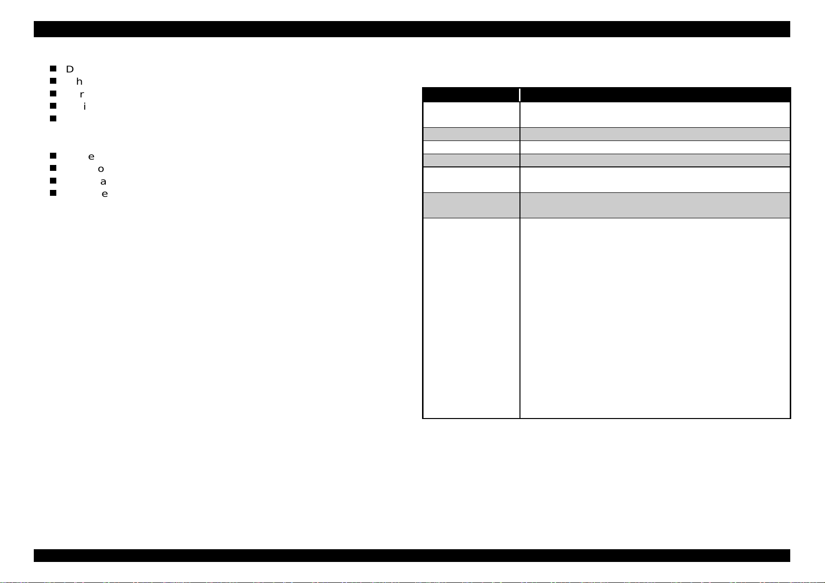
REVISION STATUS
Rev. Date Page(s) Contents
A 1998/01/23 All First release
B 1998/03/10
4-68∼4-93
4-8
4-59
4-60
Chapter4
• Added “Disassembly and Assembly for ASF Unit”.
• Modified flow chart for disassembling the mechanism
according to addition of “Disassembly and Assembly for ASF
Unit”.
• Added “CAUTION”.
• Added sentences to “CHECKPOINT”.
• Word “phase” is replaced by “alignment”.
Page 6

TABLE OF CONTENTS
PRODUCT DESCRIPTION
1.1 FEATURES....................................................................................................................................................................1-1
1.2 SPECIFICATIONS.........................................................................................................................................................1-4
1.3 ADDING PAPER GUIDE ROLLER UNIT.....................................................................................................................1-46
OPERATING PRINCIPLES
2.1 FEATURE......................................................................................................................................................................2-1
2.1.1 Operating Principles of Printer Mechanism.....................................................................................................................................2-1
2.1.1.1 Printing Mechanism...................................................................................................................................................................2-2
2.1.1.2 Carriage Mechanism.................................................................................................................................................................2-3
2.1.1.3 Paper Feed Mechanism............................................................................................................................................................2-5
2.1.1.4 Upper Surface Sensor Mechanism ...........................................................................................................................................2-7
2.1.1.5 Paper Return Mechanism..........................................................................................................................................................2-8
2.1.1.6 Lifter Gear Train Mechanism.....................................................................................................................................................2-9
2.1.1.7 Hopper 5mm Down Mechanism..............................................................................................................................................2-10
2.1.1.8 Sub Roller Gear Train Mechanism..........................................................................................................................................2-13
2.1.1.9 Gear Train Change with Hopper installed ...............................................................................................................................2-14
2.1.1.10 Ink Engage/Disengage Mechanism.......................................................................................................................................2-16
2.1.1.11 PG Disengage Mechanism....................................................................................................................................................2-18
2.1.1.12 Ink Valve Mechanism............................................................................................................................................................2-20
2.1.1.13 Friction Release Mechanism.................................................................................................................................................2-21
2.1.1.14 Gear Train Block Diagram.....................................................................................................................................................2-23
Page 7

2.1.2 Outline of Electrical Circuit..............................................................................................................................................................2-24
2.1.2.1 C228 PSB Board.....................................................................................................................................................................2-24
2.1.2.2 C228 DRV Board.....................................................................................................................................................................2-26
2.1.2.3 C228 Main Board ....................................................................................................................................................................2-27
TROUBLESHOOTING
3.1 FEATURES....................................................................................................................................................................3-1
3.1.1 Problems relating to the printer mechanism....................................................................................................................................3-1
ASSEMBLY AND DISASSEMBLY
4.1 OVERVIEW....................................................................................................................................................................4-1
4.1.1 Precautions.........................................................................................................................................................................................4-1
4.1.2 Tools....................................................................................................................................................................................................4-2
4.1.3 Screws.................................................................................................................................................................................................4-2
4.2 DISASSEMBLY................................................................................................................ .............................................4-2
4.2.1 Housing Upper Removal....................................................................................................................................................................4-3
4.2.2 Housing Front Unit Removal .............................................................................................................................................................4-5
4.2.3 Mechanism Unit Removal ..................................................................................................................................................................4-6
4.2.4 MB Rear Unit Removal .......................................................................................................................................................................4-7
4.2.5 Disassembling the Mechanism..........................................................................................................................................................4-8
4.2.5.1 Discharge Brush Removal.........................................................................................................................................................4-9
4.2.5.2 Paper Guide Assembly, Cover Removal.................................................................................................................................4-10
4.2.5.3 Print Head Removal................................................................................................................................................................4-11
4.2.5.4 MB Front Unit Removal...........................................................................................................................................................4-13
4.2.5.5 Fan Assembly Removal ..........................................................................................................................................................4-15
4.2.5.6 PS Unit Removal.....................................................................................................................................................................4-16
Page 8

4.2.5.7 Motor Assembly, PF Removal.................................................................................................................................................4-16
4.2.5.8 Motor Assembly, CR Removal ................................................................................................................................................4-17
4.2.5.9 Motor Assembly, ASF Removal ..............................................................................................................................................4-18
4.2.5.10 Carriage Unit Removal..........................................................................................................................................................4-19
4.2.5.11 Frame, Main, Paper Eject Removal ......................................................................................................................................4-22
4.2.5.12 Paper Guide Upper Unit Removal.........................................................................................................................................4-26
4.2.5.13 Pump Frame Removal ..........................................................................................................................................................4-27
4.2.5.14 Frame, Main, PF Removal ....................................................................................................................................................4-28
4.2.5.15 ASF Unit Removal.................................................................................................................................................................4-31
4.2.5.16 Upper Surface Sensor Removal............................................................................................................................................4-32
4.2.5.17 PE Sensor Removal..............................................................................................................................................................4-33
4.2.5.18 PR Sensor Removal..............................................................................................................................................................4-34
4.2.5.19 HP Sensor Removal..............................................................................................................................................................4-36
4.2.5.20 Cable Assembly, Sensor FPC Removal................................................................................................................................4-37
4.2.5.21 Interlock Assembly Removal.................................................................................................................................................4-37
4.3 DISASSEMBLY AND ASSEMBLY FOR GEAR TRAIN...............................................................................................4-38
4.3.1 Disassembly of Gear Train...............................................................................................................................................................4-38
4.3.2 Assembling Gear Train.....................................................................................................................................................................4-46
4.4 DISASSEMBLY AND ASSEMBLY FOR ASF UNIT ....................................................................................................4-68
4.4.1 Disassembly of ASF Unit..................................................................................................................................................................4-69
4.4.2 Assembling ASF Unit........................................................................................................................................................................4-75
ADJUSTMENT
5.1 OVERVIEW....................................................................................................................................................................5-1
5.1.1 Conditions which adjustment is required ........................................................................................................................................5-1
5.1.1.1 Resetting Initial Ink Charge Flag ...............................................................................................................................................5-3
5.1.1.2 Re-input the Model Name .........................................................................................................................................................5-6
5.1.1.3 Head Voltage Value Adjustment ...............................................................................................................................................5-8
Page 9

5.1.1.4 Head Angular Adjustment .......................................................................................................................................................5-11
5.1.1.5 Head Height Adjustment .........................................................................................................................................................5-18
5.1.1.6 Head Gap Adjustment.............................................................................................................................................................5-22
5.1.1.7 Bi-D Adjustment ......................................................................................................................................................................5-27
5.1.1.8 Uploading of Firmware............................................................................................................................................................5-32
5.1.1.9 Parallelism Adjustment............................................................................................................................................................5-34
5.1.1.10 Upper Surface Sensor Positioning Adjustment.....................................................................................................................5-37
MAINTENANCE
6.1 CLEANING ....................................................................................................................................................................6-1
6.2 MAINTENANCE.............................................................................................................................................................6-2
6.2.1 Head cleaning .....................................................................................................................................................................................6-2
6.2.2 Maintenance Request.........................................................................................................................................................................6-3
6.3 LUBRICATION AND ADHESION ..................................................................................................................................6-4
APPENDIX
7.1 CONNECTOR SUMMARY.............................................................................................................................................7-1
7.2 EEPROM ADDRESS MAP ............................................................................................................................................7-5
7.3 COMPONENT LAYOUT ..............................................................................................................................................7-10
7.4 CIRCUIT DIAGRAM.....................................................................................................................................................7-13
Page 10

PRODUCT DESCRIPTION
&+$37(5
Page 11
EPSON Stylus Pro 5000 Chapter1 Product Description
1.1 FEATURES
EPSON Stylus Pro 5000 is a 6-color ink jet printer , which can output colors
for the professional level. Major features are following.
Professional color print quality
1440(H) x 720(V) dpi printing at the highest resolution setting.
Photo reproduction quality(6 color printing, C.M, Y, K, LC, LM)
By micro dot + super micro dot, super fine printing equivalent to
Comoro Wide is available.
PostScript printing(option)
High speed printing
Color 360 dpi A4: 1.1 PPM
Color 720 dpi A4: 0.39 PPM
Built in 3 types of interfaces
Bi-directional parallel interface (IEEEP1284.4/ECP support)
Mac. Serial interface(up to approx. 1.8M bps)
Type-B interface (SIM for copying up to approx. 98M is available to
install on the same board;C228 main board)
Low running cost
Long life ink cartridge;
Black: 3200 papers, Yellow: 3200 papers, Cyan/Magenta:3000 papers
(5% ECOMA duty printing)
Independent 4 colors ink cartridges: Black, Yellow, Cyan including
with light cyan, Magenta including light magenta.
Ink quantity sensor.
Note)
After ink near end is detected by the mechanical switch, the
firmware counts the determined absorbing quantity.
Paper handling
Double bin ASF(second bin option)
Manual feeding from the top cover of first bin and from the rear with
opened rear cover.
Paper volume for ASF/Paper size sensor/Paper type sensor
Note)
Those sensors do not work correctly, if users set the paper size
or media type lever wrong.
Increased paper loading capacity in the paper tray (55 g/m
sheets/ Standard, option ASF)
Windows/Macintosh exclusive
2
250 cut
Rev.A
Note)
Cyan/Magenta ink is united as one, which light color and
ordinary color ink are separated. The reason why that ink life span is
not so different from others even though they are separated is that
users are usually unable to perform printing which require strict
separation of light color and ordinary color. Therefore, since light color
and ordinary color inks are adjusted to be used alternately on the
application, the life span of Cyan/Magenta does not become simply
half life span of the other inks.
1-1
Page 12
EPSON Stylus Pro 5000 Chapter1 Product Description
2
Following table shows optional items for Stylus Pro 5000.
CHECK POINT
9
Since there are many kinds of exclusive papers,
please refer to “Special Media” on the Reference
Guide for Stylus Pro 5000.
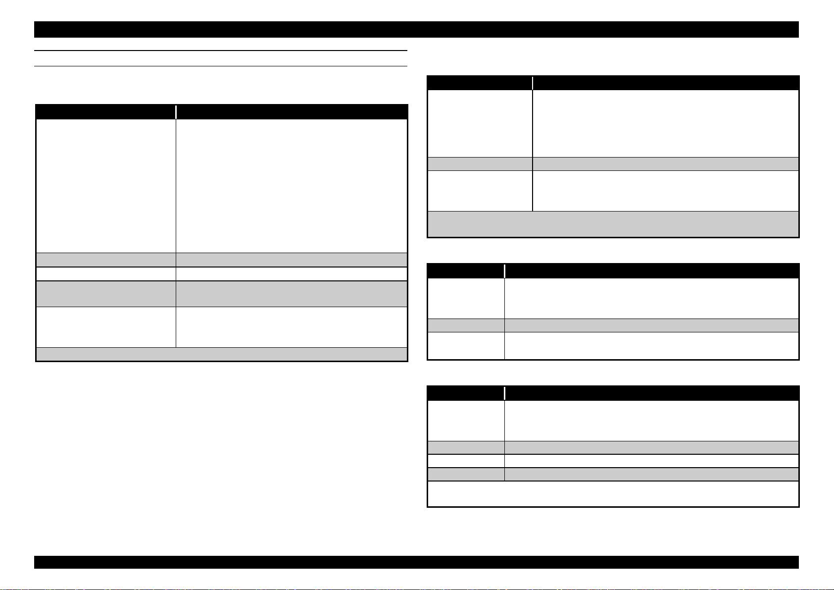
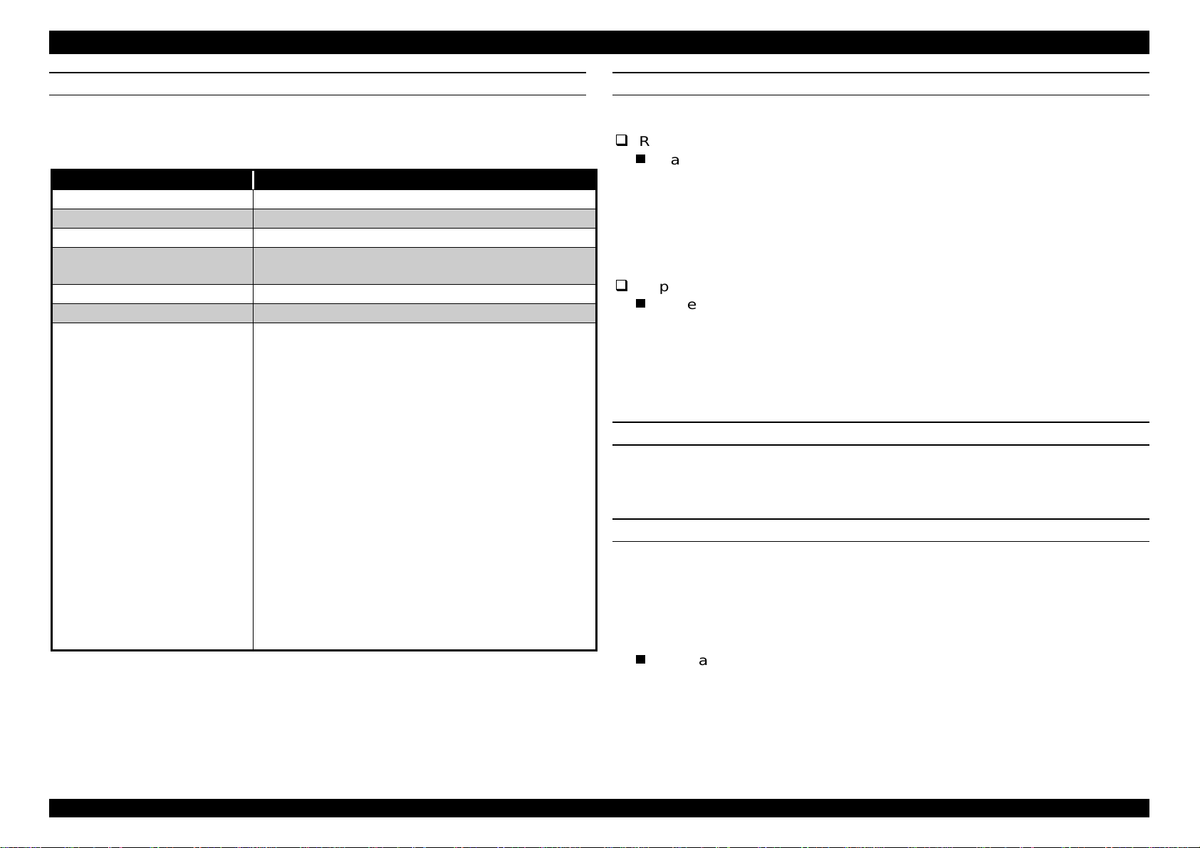
Table 1-1. Optional Items and Available Consumable
Name Remark Code No.
Ink cartridge Black ink cartridge S020118
Cyan (including light
cyan)
Magenta(including light
magenta)
Yellow S020122
Paper tray unit
Exclusive Paper Refer to the reference
SIMM memory Max.96MB(32MB x3), 72
Type-B I/F Card 32KB Serial interface
B5 ∼A3 (55g/m2:250
sheet)
guide
pins
card
LocalTalk
Co-ax interface card C82314*
Twin-ax interface card C82315*
Ethernet interface card C82357*
Bi-directional Parallel
interface card
TM
interface card C82312*
S020147
S020143
C81275*(lower paper
cassette)
C81276*
---
---
C82307*/C82308*
C82345*
Note) *
Rev.A
The asterisk is a substitute for the last digit, which varies by country.
1-
Page 13
EPSON Stylus Pro 5000 Chapter1 Product Description
3
1.2 SPECIFICATIONS
PRINTING SPECIFICATION
Print method: On demand MACH ink jet
Nozzle configuration Black - 64 nozzles
Color(5 colors) - 64 nozzles for each
color(total: 320 colors, Y, M, C, LM, LC)
Print direction Bi-direction with logic seeking
Print speed See the tables below
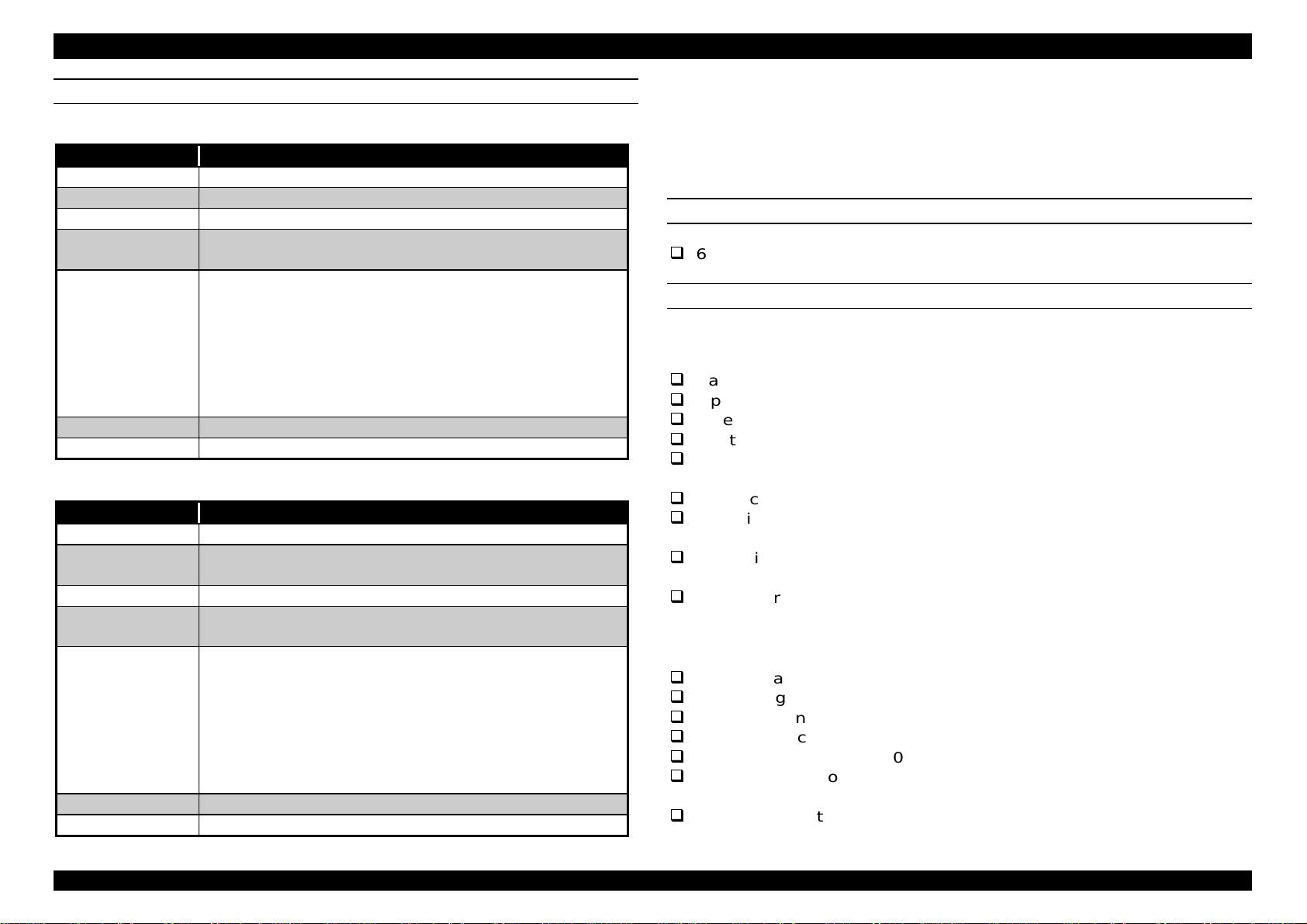
Table 1-2. Character Mode
Item Content
Character quality High quality
Character pitch 10 CPI (Pica)
Printable columns 127 columns
LQ speed 200 CPS*
Note*)
This value is the speed of one print-pass in which the ¼ of character
matrix is printed.
Table 1-3. Raster Graphics Mode
CHARACTER SPECIFICATION
Character tables: 2 international character sets;
PC437(US, Standard Europe)
PC850(Multilingual)
Type face: Bit map LQ font
EPSON courier 10 CPI
CONTROL CODE
ESC/P Raster
EPSON Remote command
PAPER FEED SPECIFICATION
Feeding method: Friction feed with ASF
Line spacing: 1/6 inch or programmable at 1/360 inch
Paper path: Cut-sheet ASF
Paper feeding: Standard cassette, optional lower paper
cassette, front manual feeding, rear manual
feeding.(All friction feeding)
Feed speed 79 ms. (1/6 inch paper feeding)
6 inch/sec.(Continuous paper)
Horizontal
Resolution
360 dpi 323mm(12.7 inch) 4578 20 IPS
720 dpi 323mm(12.7 inch) 9156 20 IPS
Note)
20 IPS is equivalent to 200 CPS at printing 10 CPI.
Printable Area Available dot CR speed (IPS)
Rev.A
1-
Page 14
EPSON Stylus Pro 5000 Chapter1 Product Description
4
PAPER SPECIFICATION
Table 1-4. Cut sheet specification
Item Remark
Paper size
Thickness
Weight
Quality Exclusive paper, Bond paper, PPC, Special
Paper
Note1)
No curled, wrinkled, scuffing or torn paper be used.
•Super A3 327 mm(W) x 483 mm(L)
•A3 297 mm(W) x 420 mm(L)
•A5 148mm(W) x 210 mm(L)
•B4 257 mm(W) x 364 mm(L)
•Letter 216 mm(W) x 279 mm(L)
•A4 210 mm(W) x 297 mm(L)
•B5 182 mm(W) x 257 mm(L)
•Legal 216 mm(W) x 356 mm(L)
•Statement 139.7 mm(W) x 215.9 mm(L)
•Exclusive 190.5 mm(W) x 254 mm(L)
0.08 mm(0.003”) ∼ 0.11 mm(0.004”)
64 g/m2 (17lb.) ∼ 90 g/m2 (24lb.)
papers.
•Regular plain paper
•EPSON Photo Quality Ink Jet Paper
•EPSON Photo Paper
Table 1-5. Transparency and Glossy film and paper specification
Item Remark
Paper size
Thickness 0.075 mm(0.003”) - 0.085 mm(0.0033”)
Paper
Note)
Note**)
Size
Thickness Less than 0.23 mm(0.0091”)
Paper
Transparency printing is only available at normal temperature.
Glossy film only.
Item Remark
•Super A3/B 13”(W) x 19”(L)
•A3 297 mm(W) x 420 mm(L)
•A4 210 mm(W) x 297 mm(L)
•Letter 216 mm(W) x 279 mm(L)
•A6 105 mm(W) x 148 mm(L)**
•EPSON Photo Quality Glossy Film
•EPSON Photo Quality Glossy Paper
•EPSON Ink Jet Transparencies
Table 1-6. Index card specification
•A6 Index card: 105 mm(4.1”)(W) x 148 mm(5.8”)(L)
•5x8” Index card 127 mm(5.0”)(W) x 203 mm(8.0”)(L)
•10x8” Index card 127 mm(5.0”)(W) x 203 mm(8.0”)(L)
•EPSON Photo Quality Ink Jet Card
•EPSON Photo Card
Rev.A
Table 1-7. Envelope specification
Item Remark
Size
Thickness 0.16 mm(0.006”) - 0.52 mm(0.02”)
Weight 45 g/m2 (12lb.) - 75 g/m2 (20lb.)
Quality Bond paper, Plain paper, Air mail
Note)
Note)
Envelope printing is only available at normal temperature.
Keep the longer side of the envelope horizontally at setting.
•No.10 241 mm(9 1/2”)(W) x 104.8 mm(4 1/8”)(L)
•DL 220 mm(8.7”)(W) x 110 mm(4.3”)(L)
•C6 162 mm(6.4”)(W) x 114 mm(4.5”)(L)
1-
Page 15
EPSON Stylus Pro 5000 Chapter1 Product Description
5
INK CARTRIDGE
Table 1-8. Black, Yellow Ink Cartridge
Item Specifications
Type Exclusive ink cartridge
Color Black, Yellow
Print capacity 3200 pages/A4 (360 dpi, ECOMA 5% duty)
Validity 2 years from production date(sealed in package, or
being installed to the printer)
Environmental
conditions
Dimension 25.1 mm(W) x 139.6 mm(D) x 105.3 mm(H)
Weight Approximately 200g
Item Specifications
Type Exclusive ink cartridge
Color Magenta +Light magenta(I/C1), Cyan + Light
Print capacity 3000 pages/A4 (360 dpi, 5% duty)
Validity 2 years from production date(sealed in package, or
Environmental
conditions
Dimension 35.1 mm(W) x 140.9 mm(D) x 105.3 mm(H)
Weight Approximately 200g
•Transit: −30°C ∼ 60°C
(within 120 hours at 60°C, and within a month at
40°C)
•Package storage: −30°C ∼ 40°C
(within a month at 40°C)
•Storage(installed to the printer):−20°C ∼ 40°C
(within a month at 40°C)
Table 1-9. Magenta and Cyan Ink Cartridge
cyan(I/IC2)
being installed to the printer)
•Transit: −30°C ∼ 60°C
(within 120 hours at 60°C, and within a month at
40°C)
•Package storage: −30°C ∼ 40°C
(within a month at 40°C)
•Storage(installed to the printer):−20°C ∼ 40°C
(within a month at 40°C)
Note1)
Note2)
Note3)
INPUT DATA BUFFER
ELECTRIC SPECIFICATION
1) 120V version
2) 220-240V version
Ink cartridge can not re-fill, only ink cartridge is prepared for article of
consumption.
Do not use the ink cartridge which was passed away the ink life.
Ink will be frozen under -15°C environment, however it will be
useable after placing it more than 3 hours at room temperature.
6 K-byte
Rated voltage: AC 120 V
Input voltage range: AC 99 V - 132 V
Rated frequency range: 50 - 60 K Hz
Input frequency range: 49.5 - 60.5 Hz
Rated current: 1.0A (Max.1.6A)
Energy Star compliant
Power consumption: Approx. 32W(ISO/IEC 10561 Letter pattern)
Insulation resistance: 10 M ohms min. (between AC line and chassis,
DC 500 V)
Dielectric strength: AC 1000 V rms. 1 minute or AC1200 V rms.
1 second(between AC line and chassis)
Sneak current: Less than 0.25 mA
Rated voltage: AC 220 V - 240 V
Input voltage range: AC 198 V - 264 V
Rated frequency range: 50 - 60 Hz
Input frequency range: 49.5 - 60.5Hz
Rated current: 0.5 A(Max.0.8 A)
Power consumption: Approx. 32 W(ISO/IEC 10561 Letter pattern)
Energy Star compliant
Insulation Resistance: 10 M ohms min.(between AC line and chassis,
DC 500 V)
Rev.A
1-
Page 16
EPSON Stylus Pro 5000 Chapter1 Product Description
6
Dielectric strength: AC 1500 V rms. 1 minute(between AC line and
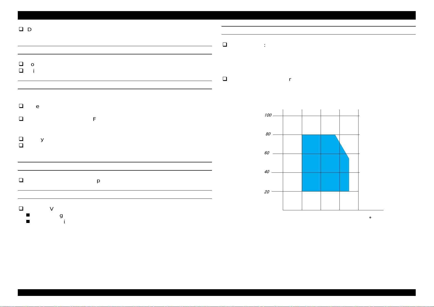
ENVIRONMENT CONDITION
chassis)
Temperature: Operating: 10°C ∼ 35°C
RELIABILITY
Storage: −20°C ∼ 40°C
Non-operating: −20°C ∼ 60°C
Total print volume: 75,000 pages (A4, letter)
Print head life: 2000 million dots/nozzle
SAFETY APPROVALS
Note)
Within 1 month at 40°C, within 120 hours at 60°C
Humidity: Operating: 20% ∼ 80% RH (without condensation)
Storage: 20% ∼ 85% (without condensation)
Non-operating: 5% ∼ 85% (without condensation)
1)120 V version
Safety standards: UL1950 with D3
CSA22.2 No.950 with D3
EMI: FCC part15 subpart B class B
Note)
Refer to the figure below.
Humidity
(% RH)
CSA C108.8 class B
2)220-240 V version
Safety standards: EN 60950 (VDE, NEMKO)
EMI: EN 55022 (CISPR Pub.22) class B
AS/NZS 3548 class B
ACOUSTIC NOISE
Level: Approx.47dB(A) (According to ISO 7779)
CE MARKING
220-240 V version
Low Voltage Directive 73/23/EEC :EN60950
EMC Directive 89/336/EEC :EN55022 Class B
EN61000-3-2
EN61000-3-3
EN50082-1
IEC801-2
IEC801-3
IEC801-4
Rev.A
10 20 30 40
Tem perature
( C )
Figure 1-1. Temperature/Humidity Range
1-
Page 17
EPSON Stylus Pro 5000 Chapter1 Product Description
7
Resistance to vibration: Operating: 0.15G, 10 ∼ 55 Hz X,Y,Z directions
Non-operating: 0.50G, 10 ∼ 55 Hz X,Y,Z
directions
Resistance to shock: Operating: 1G, within 1 ms X,Y,Z directions
Non-operating:2G, within 2 ms X,Y,Z
directions
Note1)
Note2)
Note3)
Note4)
During non-operating, make sure that the cap is capped.
During the transport, make sure that the head is capped and ink
cartridge is installed to the printer.
If the head is not capped at the power-off state, turn the printer on
while the ink cartridge is installed, and turn off the power after
capping the head.
Ink will be frozen under −15°C environment, however it will be
useable after placing it more than 3 hours at 25°C.
SERIAL INTERFACE SPECIFICATION
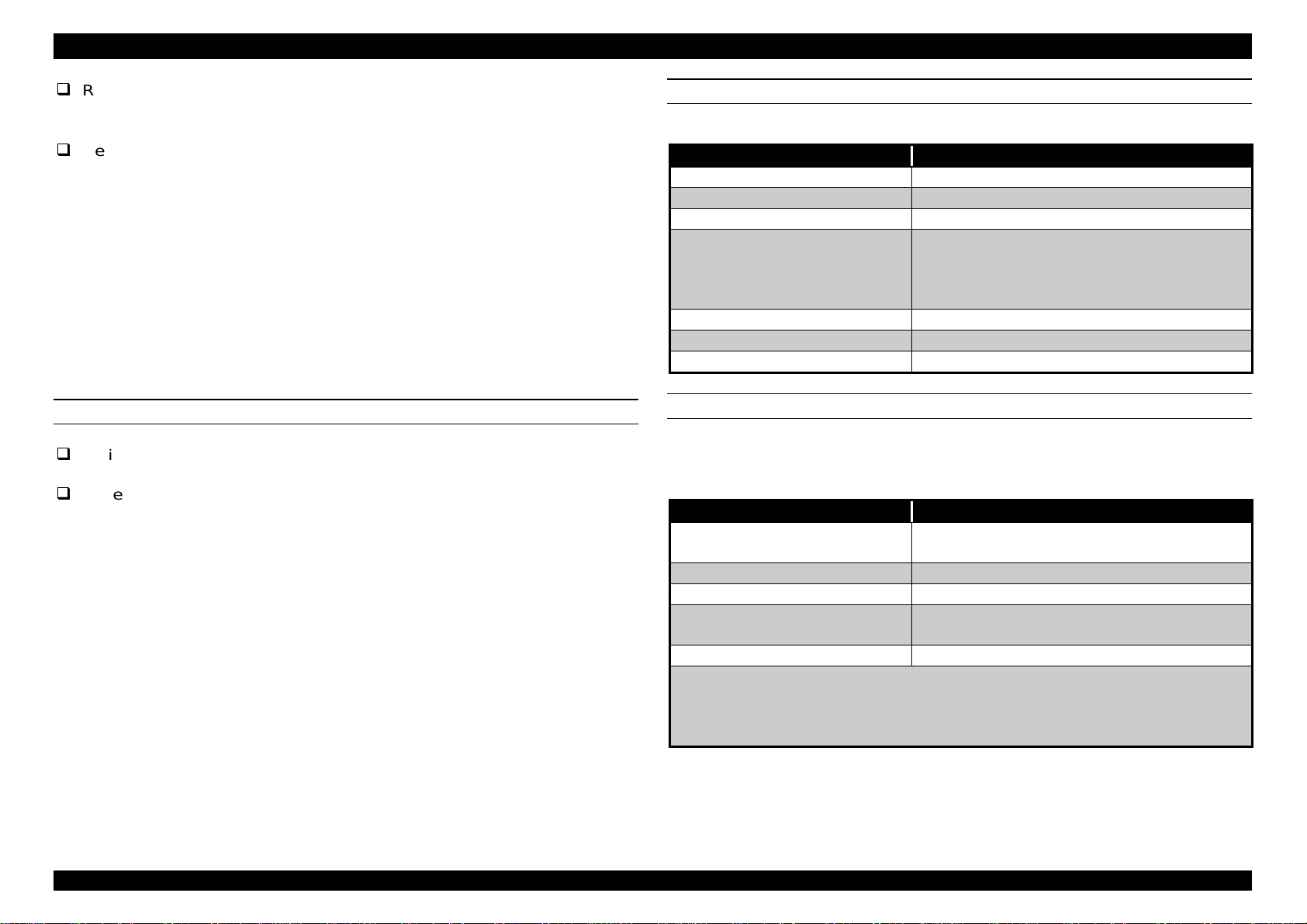
Table 1-10. Serial Interface
Item Content
Transmission mode Based on RS-423
Synchronization Synchronous
Transfer speed About 1.8M bps
Data format Start bit: 1bit
Data bit: 8bit
Parity bit: none
Stop bit: 1bit
Handshaking X-ON/X-Off, DTR protocol
Adaptable connector 8-pin mini circular connector
Recommended I/F cable Apple system peripheral-8cable
PHYSICAL SPECIFICATION
Weight: 22 Kg (only a main frame)
Dimension: 640 mm(W) x 439 mm(D) x 224 mm(H)(Body only)
640 mm(W) x 704 mm(D) x 224 mm(H)(Printing on A3
size paper tray)
640 mm(W) x 584 mm(D) x 318 mm(H)(Printing on A4
size paper, optional cassette installed)
PARALLEL INTERFACE
[Compatibility Mode]
Table 1-11. Compatibility Mode
Item Content
Transmission mode 8-bit Parallel, IEEE-1284 compatibility
mode
Synchronization By STROBE pulse
Handshaking By BUSY and ACKLG signal
Logic Level TTL compatible level (IEEE-1284 Level 1
device)
Adaptable connector 57-30360(amphenol) or equivalent
Note1):
Note2):
Note)
Recommend to use short interface cable according to your
necessity.
Use the twist pair line for each control signal of input connector
and connect the return side to the signal ground.
BUSY signal is set high before setting either /ERROR low or PE high
and held high until all these signals return to their inactive state.
Rev.A
1-
Page 18
EPSON Stylus Pro 5000 Chapter1 Product Description
8
Busy signal is at high level in the following cases;
During data entry(see Data transmission timing)
When input data buffer is full
During /INT signal is at low level or during hardware initialization
During printer error (See /ERROR signal)
When the parallel interface is not selected
ERROR signal is at low level when the printer is one of the following states.
Printer hardware error (fatal error)
Paper out error
Paper jam error
Ink out error
Note)
PE signal is at high level during paper-out error.
[Nibble Mode]
Table 1-12. Nibble Mode
Item Content
Transmission
mode
Synchronization Refer to IEEE-1284 specification
Handshaking Refer to IEEE-1284 specification
Signal level TTL level (IEEE-1284 level 1 device)
Adaptable
connector
Data transfer
timing
Extensibility
request data
IEEE-1284 nibble mode
See forward channel
Refer to IEEE-1284 specification
The printer responds affirmatively when the
extensibility request values are 00H or 04H, that
mean,
00H :Request nibble mode reverse channel
transfer.
04H :Request device ID; Return Data using Nibble
Mode Rev channel transfer.
The printer sends following device ID string when it is
requested.
[00H] [3BH]
MFG : EPSON
CMD : ESCPL2, BDC
MDL : Stylus[SP]Pro[SP]5000;
CLS : PRINTER
Note)
[00H] denotes a hexadecimal value of zero.
MDL value depends on the EEPROM setting.
Rev.A
1-
Page 19
EPSON Stylus Pro 5000 Chapter1 Product Description
9
PARALLEL INTERFACE (CONT.)
[ECP Mode]
Table 1-13. ECP Mode
Item Content
Transmission mode IEEE-1284 ECP mode
Synchronization Refer to IEEE-1284 specification
Handshaking Refer to IEEE-1284 specification
Signal level TTL level (IEEE-1284 level 1 device)
See forward channel
Adaptable connector See forward channel
Data transfer timing Refer to IEEE-1284 specification
Extensibility request data The printer responds affirmatively when the
extensibility request values are 10H or 14H,
that mean,
10H :Request ECP mode reverse
channel transfer.
14H :Request device ID; Return Data
using ECP Mode Rev channel
transfer.
The printer sends following device ID string
when it is requested.
[00H] [3BH]
MFG : EPSON
CMD : ESCPL2, BDC
MDL : Stylus[SP]Pro[SP]5000
CLS : PRINTER
Note)
[00H] denotes a hexadecimal value of
zero. MDL value depends on the
EEPROM setting.
TYPE B OPTIONAL INTERFACE SPECIFICATION
Type-B interface level 2 is supported.
Reply message (Short version):
Case of using Co-ax / Twin-ax I/F card:
Main Type: MTP48p, PW127cl10cpi, PGR(KAxxxx)rev,
AP1200ma
Product Name: Stylus[SP]Pro[SP]5000
Emulation Type: ESCPL2-00
Entity Type: EPSONLQ2
Reply message
Case of using except Co-ax / Twin-ax I/F card
Main Type: MTP48p, PW127cl10cpi, PGR(KAxxx)rev,
AP1200ma, SPD0fast
Product Name: Stylus[SP]Pro[SP]5000
Emulation Type: ESCPL2-00
Entity Type: ESPONLQ2
BUFFER OPERATION
Stylus Pro5000 starts sending BUSY signal when it acknowledges no
available area left in the buffer. When the host keeps receiving this signal
for a long time, it acknowledges as time out and stops sending data.
INTERFACE SELECTION
The printer has 3-built in interfaces; the parallel interface and serial
interface, and has 1 optional Type-B interface card slot. These interfaces
are selected manually by the default setting mode or selected automatically.
(However, it is necessary to set these settings within the maintenance mode
level 1 of the panel operation.)
Manual Selection:
One of three interfaces can be selected by the default setting mode.
Rev.A
1-
Page 20

EPSON Stylus Pro 5000 Chapter1 Product Description
0
Automatic Selection:
The automatic interface selection is enabled by the default setting
mode. In this automatic interface selection mode, the printer is
initialized to the idle state scanning which interface receives data
when it is powered on. Then the interface that receives data first is
selected. When the host stops data transfer and the printer is in the
stand-by state for the seconds, the printer is returned to the idle
state. As long as the host sends data or the printer interface is busy
state, the selected interface is let as it is.
Following explains conditions of other interfaces when a particular interface
is selected.
When the parallel interface is not selected, the interface gets into
BUSY state. At this time, LH signal is set to “L”. That means blocking
power supply and no responds from 1284. Therefore, it is necessary
for the host, which requires Reverse transfer, to check LH state.
When the serial interface is not selected, the interface sets the DTR
signal MARK.
When the optional interface is not selected, Off-Line bit is set to Main
Status Register(MNSTS).
When the printer is initialized or returned to the idle state, Parallel
interface becomes the ready condition and DTR of serial interface
becomes SPACE(Low) condition and reset off-line bit of Main Status
Register(MNSTS)to, option interface.
/INIT signal on the parallel interface is not effective while that
interface is not selected or nibble Mode, ECP Mode.
Rev.A
1-1
Page 21
EPSON Stylus Pro 5000 Chapter1 Product Description
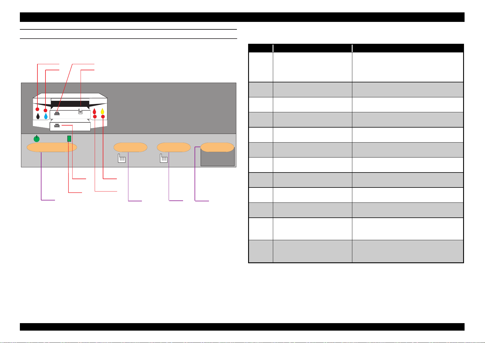
CONTROL PANEL
There are 4 non-lock push buttons and 8 LEDs. Each button function and
indicator are explained briefly below and on your right.
A
B
O perate
1
C
D
C leaningReset
3 se c 3 sec
G
H
E
F
2 3 4
Eject
C ontinue
Figure 1-2. Control Panel
Table 1-14. Control Panel Function
No. Button / Indicator Function
1 Operate button
(power)
Power source switch on the
secondary side.
Note)
Current is constantly flowing
in the primary side.
2 Reset button(Pressing for
Printer reset. Buffer clear.
3 sec.)
3 Cleaning button(Pressing
for 3 sec.)
4 Eject(Error recover)
button (2 sec.)
A Black I/C out indication
LED
B Cyan I/C out indication
LED
C Paper out indication LED
for cassette (paper tray) 1
D Paper out indication LED
for manual feed slots
Perform cleaning all heads of both
sides.
Ejects the paper, or recovers from
error.
Blinks for low ink quantity and light is
on for out of ink.
Blinks for low ink quantity and light is
on for out of ink.
Indication for paper out or paper
loading miss of cassette 1.
All 3 LEDs (C, D, G) blink at the
same time for paper loading miss.
E Magenta I/C out LED Blinks for low ink quantity, and light
is on for out of ink.
F Yellow I/C out LED Blinks for low ink quantity, and light
is on for out of ink.
G Paper out indication LED
for optional lower
Indication for paper out or paper
loading miss of cassette 2.
cassette (paper tray) 2.
H Operate LED
(power)
Green light is on while the current is
flowing, or receiving data, or CL
operation.
Rev.A
1-11
Page 22
EPSON Stylus Pro 5000 Chapter1 Product Description
2
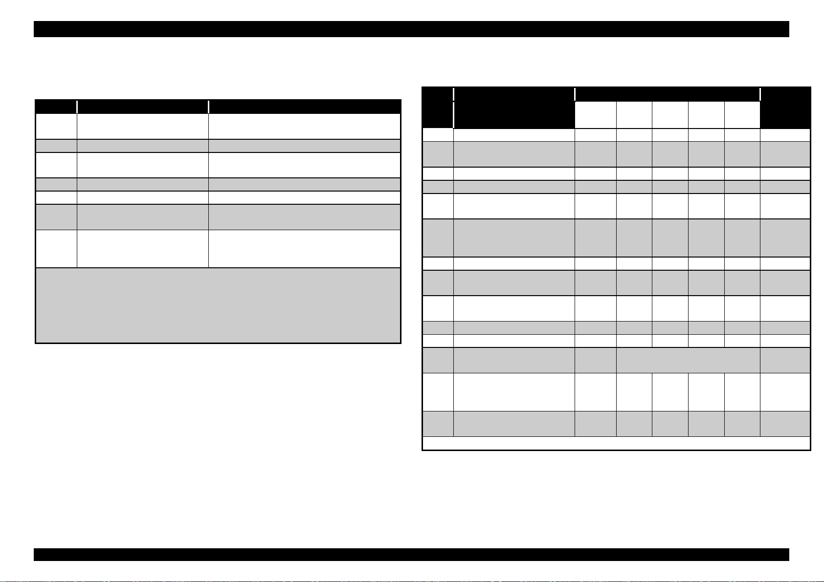
Following table shows function when the power is turned on.
Table 1-15. Functions with power on
No. Name of switch Function
1 Reset Perform status printing (Refer to
Note1)
2 Cleaning Changes paper size, type verification.
3 Eject/Continue Changes platen gap adjustment for
the manual feed slots.
4 Reset + Cleaning Changes parallel I/F ECP mode
5 Reset + Eject/Continue Enters print head alignment mode.
6 Cleaning +
Eject/Continue
7 Reset +Cleaning +
Eject/Continue
(All SW)
Note1)
Note2):
mode.
:This status printing prints firmware version, ink counter, selected
code page and nozzle check patterns. Since the value of the
waste ink counter is indicated by HEX, it is recommended to use
the exclusive service program for checking the counter value.
Refer to Table1-17 for Download of Firmware and Maintenance
Enters the maintenance mode,
level1.(Factory use only)
Enters the Firmware uploading mode.
(Factory use only)
Following table shows LED indications.
Table 1-16. Printer condition and Panel status
No. Printer Status Indicators (Figure 1-2) Priority
H AB
EF
1 Power On On --- --- --- --- 9
2 Performing Ink
sequence
3 Receiving Data blink --- --- --- --- 8
4 Paper jam --- --- blink blink blink 3
5 Cassette 1/paper out,
wrong paper feeding
6 Out of paper in
Cassette 1(paper
tray1)
7 Cassette(Paper tray)2 --- --- --- --- On 5
8 Paper out in
Cassette(Paper tray)2
9 SIMM copy error
(over flow)
10 Ink end, No I/C --- On --- --- --- 7
11 Ink low --- blink --- --- --- 7
12 Reset, Timer IC reset,
EEPROM clear
13 Maintenance request
(waste ink counter
over flow)
14 Fatal error blink All
Note):
“---“ means no changes.
blink --- --- --- --- 6
--- --- --- blink --- 5
--- --- --- On --- 5
-- --- --- --- On 5
blink On On On On 4
--- On
blink AllOnblink blink blink 2
blink
D C G No.
---
(1 sec.)
blink blink blink 1
Rev.A
1-1
Page 23
EPSON Stylus Pro 5000 Chapter1 Product Description
3
Name of
Switch
All switches
+ Power on
Cleaning +
Eject Switch
+ Power on
(Level1)
Table 1-17. Download/Maintenance Mode
Function
1.Manual feed LED turns on when the printer enters this
mode correctly. Exclusive starting command(
is transmitted on the DOS (or DOS prompt). Black ink
LED blinks during this transmission and Cyan ink LED
will be turned on when the transmission is completed
correctly.
2.Wait 2 or 3 seconds after the Cyan ink LED is turned
on. Firmware
time, Magenta ink LED is turned one during this
transmission, and Yellow ink LED is turned on when it is
completed.
3.Turn off the power.
I/F
Diseng
age
Hexade
cimal
dump
(KEYWEST.HEX
1. After the operation written in the left column
is performed, press Reset switch until the
black ink LED is turned on. During entering
this mode, black, Cyan, Magenta and Yellow
LEDs are turned on alternatively, every time
the reset switch is pressed.
2.When the black ink LED turns on, press
Eject switch to determine.
3.Press the Reset switch until the
corresponding LED turns on, according to the
following explanation.
Black ink LED→Automatic, Cyan ink
LED→Parallel, Magenta ink LED→Serial,
Yellow ink LED→Option
4.Press either Eject switch or turn the power
off for registering to EEPROM.
1.After the operation written in the left column
is performed, press Reset switch until the
Magenta ink LED is turned on. During entering
mode, black, Cyan, Magenta and Yellow LEDs
are turned on alternatively, every time the
Reset switch is pressed. Press Eject switch to
determine after Magenta LED turns on.
2.Turning power off is the only way to escape.
) is transmitted. At this
IPL2.HEX
Table 1-18. Download/Maintenance Mode(Cont.)
Name of Switch Function
Cleaning + Eject
Switch + Power on
)
P-I/F
receiving
speed
CG
Disenga
ge
1.After the operation written in the left
column is performed, press Reset
switch until the Cyan ink LED is turned
on. During entering this mode, black,
Cyan, Magenta and Yellow LEDs are
turned on alternatively, every time the
reset switch is pressed.
2.Press Eject switch to determine after
Cyan ink LED is turned on.
3.Press the Reset switch until the
corresponding LED turns on, according
to the following explanation.
Black ink LED→High speed, Cyan ink
LED→Standard
4.Press Eject switch to register in the
EEPROM.
Note)It is not registered to EEPROM, if
power is turned off without pressing
Eject switch.
1. After the operation written in the left
column is performed, press Reset
switch until the Yellow ink LED is turned
on. During entering this mode, black,
Cyan, Magenta and Yellow LEDs are
turned on alternatively, every time the
reset switch is pressed.
2.Press Eject switch to determine after
Yellow ink LED is turned on.
3. Press the reset switch until the
corresponding LED turns on, according
to the following explanation.
Black ink LED→PC437, Cyan ink
LED→PC850
4. Press Eject switch to register in the
EEPROM.
Rev.A
1-1
Page 24
EPSON Stylus Pro 5000 Chapter1 Product Description
4
Table 1-19. Download/Maintenance Mode(Cont.)
Name of Switch Function
After inputting
modes written in
the previous page,
press Cleaning,
then, Reset switch.
(Level 2)
INITIALIZATION
Stylus Pro 5000 has following 3 initializations.
Note)After entering maintenance mode level1, it
becomes EEPROM reset function by pressing
Cleaning switch, then, Reset switch.
1.Make sure that black ink LED is on. If it is not
on, press Reset switch until the black ink LED
turns on.
2.After black ink LED turns on, press Eject switch
and confirm the reset.
3.To end this operation, turn the power off.
Operator(Panel) initialization
This printer is initialized when pushing the panel reset switch, or
printer recognized the /INT signal(negative pulse) of parallel
interface. When printer is initialized, following action is performed.
1. Caps the print head
2. Ejects a paper
3. Clears input data buffer
4. Clears print buffer
5. Resets default values
SETTING VALUES BY INITIALIZATION
By performing initialization, the following items return to the initial values.
Also, the panel setting, default setting, and item that can be saved on the
remote command will be default values.
Power on (Hardware) initialization:
This printer is initialized when turning the printer power on, or printer
recognized the cold-reset command (remote RS command). When
printer is initialized, following action is performed.
1. Initializes printer mechanism
2. Clears input data buffer
3. Clears print buffer
4. Resets default values
Software initialization
The ESC@ command also initializes the printer. When printer is
initialized, following action is performed.
1. Clears print buffer
2. Resets default values
1. Page position: Page heading location as present
paper location
2. Line spacing: 1/6 inch
3. Right margin position: 127 lines
4. Left margin position: First line
5. Word pitch: 10 CPI
6. Printing mode: Text mode(Not raster graphics mode)
Rev.A
1-1
Page 25
EPSON Stylus Pro 5000 Chapter1 Product Description
5
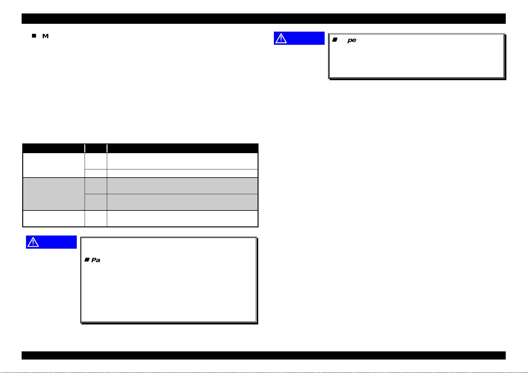
ERROR CONDITION
Stylus Pro5000 goes to error condition when it falls to the following
conditions. Out of Centronics interface signals, BUSY signal is set High and
/ERROR signal is set LOW. Then, the printer goes to unprintable state,
stopping data input from outside. Once the error happens, the printer can go
back to the standby position or ready status for printing again by removing
the error causes.
Ink near end and Ink out Error
When the printer runs out the most part of the ink of any one color, it
warns ink-low and keeps printing. When the printer runs out the whole
ink of any one color, it stops printing and indicates ink-out error. User is
requested to install a new ink-cartridge in this state.
A ink-cartridge once taken out should never be used again. Reinstallation of the cartridge not filled fully upsets the ink level detection
and may cause a serious problem in the print head as a result.
Paper out sensor
When there is no paper in the paper tray, or paper tray itself is not
installed, this sensor detects and goes paper out error.
Paper loading miss:
When printer fails to load a sheet or PE sensor does not detect the
paper on the path, it goes paper out error.
Paper Jam Error
Even when the paper feeding is performed at the power on, if the PE
sensor detects the paper on the paper path or fails to eject a paper by
FF command or Eject button, the printer considers it as paper jam and
goes to the error condition. In the Stylus Pro5000, the linear encoder
monitors detection of paper jam in the carriage running range.
No ink-cartridge
When the printer detects that ink cartridge comes off or is not installed, it
goes to the error condition.
CAUTION
Rev.A
Although there is no worry of bubble invasion by
pulling out or installing the ink cartridge, it is
necessary to pay attention to the following points.
1)If the ink cartridge is once removed and installed
again in the condition that the ink out(end) sensor
detects the ink is still in, ink consumption based
on the previous ink life will be kept counting.
2)If the ink cartridge is once removed and the ink
cartridge whose left ink quantity is little is installed
again in the condition that the ink is still in, Stylus
Pro5000 goes to the ink out error condition, even
though there is still enough ink in it.
Maintenance Request
When the total quantity of ink wasted through the cleanings and flushing
reaches to the limit, printer indicates this error and stops. The
absorber(waste ink pad) in the printer enclosure is needed to be
replaced with new one by a service person. This error does not recover
until the waste ink pad is replaced and “0” is written to the particular
address in the EEPRON by a service man.
Fatal Errors
When fatal errors such as carriage control error or CG access error are
detected, the printer goes to error condition and stops. Repair service is
required for this error.
1-1
Page 26
EPSON Stylus Pro 5000 Chapter1 Product Description
6
PANEL SETTING FUNCTION
Here explains input method for each panel setting.
Printing nozzle check pattern and printer configuration
•Operation: Reset SW + Power On
•Exit: Power Off
•Function: (Power LED blinking while in this mode)
1)Reset SW + Power on →2)Position change
to thick→3)Starts printing pattern→
4)Printing 1-page→5)Eject paper→6) Stand by
mode in self-test by pressing →Refer to
followings.
[Pressing Cleaning SW: in standby mode only]
1)Execute cleaning→2)Eject paper 3)Reprint self test
page→4)self-test stand by mode.
[Pressing Eject SW: in standby mode only]
1)Feed paper→2)Reprint self test page→3)self-test
stand by mode.
Note)
Ignore Cleaning SW while printing and Power off to exit this mode.
K 00227A A :0D 95 B :0D A F D :002C E 2C 0
Current Settings
P a p e r S iz e /T y p e C h e c k : O n
P a r a lle l I/F E C P M o d e : O ff
Platen G ap A djustm ent for M anual Feed S lots : Fixed (thick paper)
CHECK POINT
9
Even if Cleaning or Eject switch is pressed
during printing, the panel operation is ignored.
You can escape from the self-test mode only by
turning the power off.
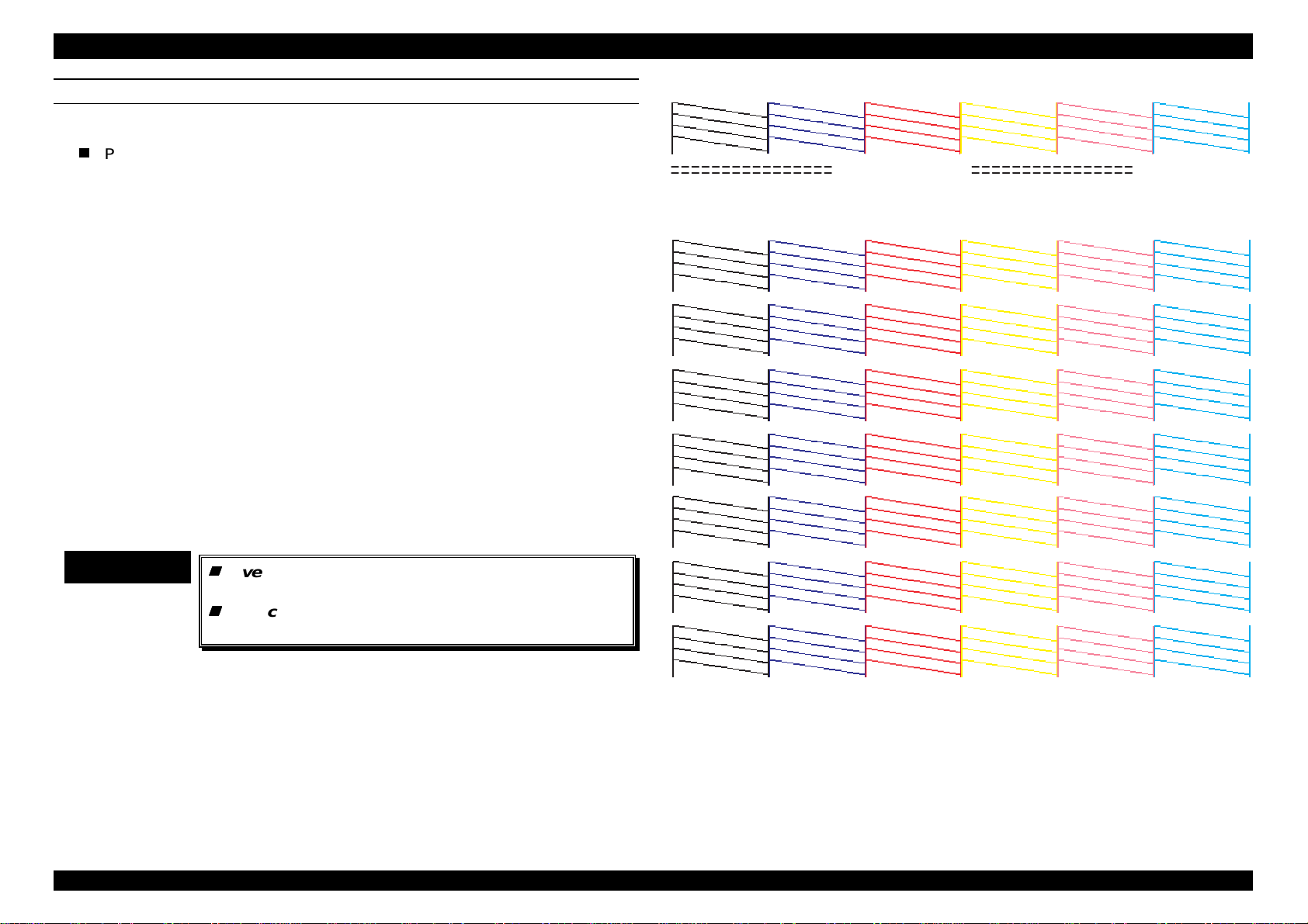
Printing Pattern: Print nozzle test pattern, firmware version, the value
of wasted ink count and current setting values are
printed. Following shows printing pattern.
Rev.A
Figure 1-3. Printing Sample
[Explanation]
K00227A: Firmware version.
A:0D95 : The present counting value of ink absorber only for
dark colors head.
1-1
Page 27

EPSON Stylus Pro 5000 Chapter1 Product Description
7
B:0DAF : The present counting value of ink absorber for light
color head only.
D: 002CE2C0 : The present counting value of waste ink absorber for
flushing.
Note)
By referring to the printing pattern on the previous page, it becomes
possible to check ink discharge conditions (or dot missing or alignment
failure) from all nozzles in each color. As an example, refer to “A” ∼ “D” lines
shown on the black nozzle pattern. “A” line is printed by black nozzle #1 to
#16, “B” line is by #17 to #32, “C” line is by #33 to #48, and “D” is #49 to
#64. Since the nozzle for different colors is also aligned in the same way,
you can consider in the same way.
Maintenance Error occurs at the point either A or B becomes full
counter condition. In other words, it occurs when A becomes 46650,
or B becomes 47200. Since the value is indicated by HEX indication,
it is recommended to use the exclusive program to check the counter
value.
Rev.A
1-1
Page 28

EPSON Stylus Pro 5000 Chapter1 Product Description
8
Paper check mode
This setting decides to turn the paper check function on or off. For
Stylus Pro5000, it is necessary to match the lever located paper feed
cassette(tray) above to the presently used paper type (media type)
and its size. If the PC which supports bi-directional communication is
used, it is not necessary to make this paper check setting
effective(on), because the user can change the lever positions on the
cassette, according to the error message on the PC screen.
However, if the user uses the PC which does not support the bidirectional communication, it is necessary to set this mode on the
printer body, since he/she can not check the error message on the
computer screen.
[After completing the setting, if the power is turned off]
1)Printer escapes from the selected paper check
mode.→2)Printer goes to the power off condition.
•Setting and LED indicator:
ECP mode off→Cyan LED on
ECP mode on→Black ink LED on.
•Function: 1)Reset SW+ Cleaning SW+ Power on to
enter this mode→2)Power LED turns on and
Cassette1LED blinks→
3)Indicate the current setting by blinking ink
LED.→4)Change ECP On/Off by Reset SW.
•Operation: Cleaning SW + Power on to enter this mode.
•To change paper check mode setting On/Off:
Reset SW
•Save setting: Press Eject switch or turn off the power.
•Setting and LED indicator:
Paper check On→ Black ink LED On.
Paper check Off→ Cyan ink LED On.
•Function: 1)Cleaning SW +Power on to enter this
mode→2)Power LED blinks, Cassette1 LED
turns on→3)Ink LED indicates current
setting→ 4)Change paper check On/Off by
Reset SW.
[After completing the setting, if the power is turned off]
1)Save setting→2)Exit mode→3)Power off
[After completing the setting, if Eject switch is pressed]
1)Save setting→2)Exit mode→3)Idle state
ECP Mode
•Operation: Reset SW + Cleaning SW + Power On to enter
this mode.
•To change ECP mode On/Off:
Reset SW
•Save setting : Turn off the power or press the Eject SW
[After completing the setting, if Eject switch is pressed]
1)Printer escapes from the selected paper check
mode. →2)Printer goes to the ordinal printing mode(idle state).
Rev.A
1-1
Page 29
EPSON Stylus Pro 5000 Chapter1 Product Description
9
Manual feed slots paper thickness - Auto mode
The setting for Manual feed thick paper and auto mode is the function
only to deal with using manual feed slots(front/rear). After checking the
result of the printing by the manual feeding, this function becomes
effective when the printing is blurry or faint. The reason why there is this
kind of function only for manual feeding is that the printer can not
recognize the paper thickness, unlike the other paper feed cassettes.
There is no influence on the other paper feeding path(or standard
cassette or optional cassette), when this function becomes effective.
Also, unless this function is set effective, manual paper feeding always
make PG(platen gap) big or wider and perform printing. Following shows
conditions when the PG becomes wider(big).
Table 1-20. Setting conditions when PG becomes thick paper mode
Setting No. Conditions
Setting on the
Driver side.
Lever setting on
the cassette side.
Special Panel
setting.
1 In case A4 size paper (landscape) is set.
2 In case SF exclusive paper (landscape) is set.
3 In case Media type is the combination of
ordinary paper and paper size A4(landscape).
4 In case Media type is the combination of SF
exclusive paper and A4 size(landscape).
5 In case of thick paper mode for the manual
feed.
CAUTION
Paper Feed from Manual Paper Feed Slot
Priority order1.:PG is wider(big) if thick paper
mode is set.
Priority order2.:In case, media type is set to the
envelope.
•Operation: Eject switch + Power on to enter this mode.
•To change setting Manual/Auto mode:
Reset SW
•Save setting: Turn off the power or press the Eject switch.
•Setting and LED indication: *Auto→Black ink LED On. Platen gap
is defined by platen gap command
‘PG’.
*Manual feed(thick paper)→Cyan ink
LED on. Platen gap ignores PG
command and uses platen gap thick
position.
•Function: 1)Eject SW + Power On to enter this
mode→2)Power LED blinks and
Cassette 2 LED turns on→3)Ink LED
indicates current setting→4)Automatic
or manual (thick paper) is changed
over everytime the Reset SW is
pressed.
Rev.A
CAUTION
According to the Table above, priority order for
each setting is determined as follows.
Paper Feed from paper feed cassette
(standard/option).
Priority order1.:In case the media type is set to
“Thick Paper”.
Priority order2.:In case there is mis-matching
between driver and lever position on the printer,
the priority is given to the driver setting, if “Ignore”
button is selected on the screen.
[After completing the setting, if the power is turned off]
1)Save setting→ 2)Exit setting mode →3)Printer goes
to the power off condition.
[After completing the setting, if Eject switch is pressed]
1)Save setting→ 2)Exit setting mode →3)Printer goes
to the ordinary printing mode.(idle state)
1-1
Page 30
EPSON Stylus Pro 5000 Chapter1 Product Description
0
Select I/F mode(Cont1. from Maintenance mode)
Maintenance Mode 1
• Operation: Cleaning SW + Eject SW + Power ON to enter this
mode.
• To change maintenance item:
Reset SW
• Determine the selection(maintenance item):
Eject SW
• Maintenance item and LED indicator:
I/F selection → Black ink LED is on.
Parallel input speed→Cyan ink LED is on.
HEX dump→Magenta ink LED is on.
Character set→Yellow ink LED is on.
• Function: 1)Cleaning SW + Eject SW+ Power ON to enter this
mode→2)Power LED blinks. Manual cassette(tray),
Cassette1 and 2 turn on→3)Ink LED indicates current
setting→4) Paper check, I/F selection, Parallel input
speed, Hex change is changed over everytime the
Reset SW is pressed.
Ink LED turn on in the order of left to right and returns
to left side.
[In case of pressing Eject SW]
1)Select item(Data registration)→2)Exit this mode→3)Enter each setting
mode.
CAUTION
Following explains setting of each item in the
maintenance mode selection.
• Operation: After Eject SW + Power ON, turn the black ink LED
on by pressing Reset SW, and determine that
selection by pressing Eject SW.
• To select I/F mode:
Reset SW(Parallel→Serial→Option)
• Save setting:
Eject SW or Power off
• Setting item and LED indicator:
Auto selection setting→Black ink LED is on.
Parallel I/F mode→Cyan ink LED is on.
Serial I/F mode→Magenta ink LED is on.
Option I/F mode→Yellow ink LED is on.
• Function: 1)Select “Black” in maintenance mode to enter this
mode.→2)Power LED blinks. Cassette1 and 2 turn on
→3)Ink LED indicates current setting. →4)By pressing
Reset SW, Auto, Parallel, Option is selected in this
order. Ink LED moves left to right and return to left.
[After completing the setting, if power is turned off]
1)Save setting(Data registration)→ 2)Exit setting mode →3)Printer goes
to the power off condition.
[After completing the setting, if Eject switch is pressed
1)Save setting(Data registration)→ 2)Exit setting mode →3)Printer goes
to the ordinary printing mode(idle state).
Rev.A
1-2
Page 31

EPSON Stylus Pro 5000 Chapter1 Product Description
HEX dump mode (Cont2. from Maintenance mode)
• Operation: After pressing Eject SW + power on, turn on the
Magenta ink LED by pressing Reset SW and
determine by Eject SW. After that, HEX dump and
ordinary mode is changed over by pressing Reset
SW.
• Save setting: Press Eject SW.
• Function: 1)Enter HEX dump mode →2)Hex dump idle →3)HEX
dump printing.
Exit mode by power off.
Parallel I/F speed(/ACK plus width) (Cont3. from Maintenance mode)
• Operation: After pressing Cleaning SW + Eject SW + Power on,
turn on the Cyan ink LED by pressing Reset SW
and determine by Eject SW. After that, High speed
and standard is changed over by pressing Reset SW.
• Save setting: Press Eject SW.
• Setting item and LED indicator:
/ACK with short(0.5us)→Black ink LED is on.
/ACK with standard(2us)→Cyan ink LED is on.
• Function: 1)Select “Cyan” in maintenance mode to enter this
mode. →2)Power LED and Cassette 1 blink.
Cassette2 LED turns on. →4) Ink LED indicates
current setting. →
5)Short or Standard is changed over everytime Reset
SW is pressed.
PC437-PC850 Code Page select(Cont4.from Maintenance mode)
• Operation: After pressing Cleaning SW +Eject SW +Power on,
turn on the Yellow ink LED by pressing Reset SW
and determine by Eject SW. After that, PC-437 and
PC-850 is changed over by pressing Reset SW.
• Save setting: Power off or Eject SW
• Setting item and LED indicator:
PC437→Black ink LED is on.
PC850→Cyan ink LED is on.
• Function: 1)Select maintenance mode “Yellow” to enter this
mode. →2)Power LED and cassette 2 LED blink.
→3)Ink LED indicates current setting. →4)PC437 and
PC850 is changed over every time Eject SW is
pressed.
[In case of turning power off]
1)Save setting(Data registration)→2)Exit this mode→3)Power off
[In case of pressing Eject SW]
1)Save setting→2)Exit this mode→3)Ordinary printing mode(idle state)
[In case of turning power off]
1)Save setting(Data registration)→2)Exit this mode→3)Power off
[In case of pressing Eject SW]
1)Save setting→2)Exit this mode→3)Ordinary printing mode(idle state)
Rev.A
1-21
Page 32

EPSON Stylus Pro 5000 Chapter1 Product Description
2
Maintenance Mode 2
Reset EEPROM (Cont. from Maintenance Mode2)
This operation is to input particular address “0” in the EEPROM.
• Operation: In maintenance mode, press Cleaning SW and
then Reset SW to enter maintenance mode2.
• Select maintenance mode2 setting item:
Reset SW
• Select item: Eject SW
• Setting item and LED indicator:
Reset EEPROM→Black ink LED is on.
• Function: 1)In maintenance mode, press Cleaning SW and then
press Reset SW to enter this mode. →2)Power LED
and manual tray LED blink. Cassette 1 and 2 turn on.
→3)Ink LED indicates current setting. →
4)Ink LED moves left to right and return to left by
every Reset SW.
[In case of pressing Eject SW]
1)Save setting→2)Exit this mode→3)Execute one of setting mode.
CAUTION
There is only one available item in the maintenance
2. See the item on your right.
There is only one item that you can actually operate in the maintenance
mode2. This function is the same reset as other EEPROM reset of other
EPSON printer products.
• Operation: After entering maintenance mode, press Cleaning
SW, then, press Reset SW to enter maintenance
mode2. At this time, black ink LED is on.
Select maintenance mode 2 “BLACK” to clear
EEPROM.
• Execute: Eject SW
• Function: Pressing Eject SW clears only particular address in
the EEPROM.
• Exit: Exit this mode by power off.
Following shows items which are actually cleared by this operation.
CHECK POINT
9
Following items are reset forcefully by executing
maintenance mode2.
Waste ink counter (protect counter) is cleared.
Total power off time(timer IC) is cleared.
Cleaning counter is cleared.
The value of Auto I/F returns to Auto(initial value).
Rev.A
1-2
Page 33

EPSON Stylus Pro 5000 Chapter1 Product Description
3
Gap Adjustment Mode
This adjustment is Bi-D adjustment and head gap adjustment.
By turning on power, pressing Cleaning SW and Eject SW, the printer
enters to the gap adjustment mode and prints out the present adjustment
values.
• Select: Select most appropriate No. of line from the
samples by referring to the table below.
In this selection, LED moves from 1→7
direction by Reset SW, and 7→1 direction by
Eject SW.
CAUTION
In this gap adjustment mode, 4 printing patterns
are printed out; 1. Normal dot, 2.Micro dot, 3.BiD printing of Super micro dot, 4.Head Gap
pattern. However, in this present model, Bi-D
printing by other dots except normal dot is not
performed. The reason why Bi-D adjustments for
micro and super micro are included is for the
future use, in case of specification changes.
• Operation: Rese SW+ Eject SW + Power On to enter this mode.
After entering to the gap adjustment mode, 4
patterns(#1∼#4) of Bi-D sample with present values is
printed out. At this time, set the sample number you
want to adjust by referring to the Table below.
Table 1-21. Number selection after entering adjustment mode
No. Ink LED #1 #2 #3 #4
1 Black On Off Off Off
2 Cyan Off On Off Off
3 Magenta Off Off On Off
4 Yellow Off Off Off On
• Select setting item: Number is changed from #1 to #4
everytime Reset SW is pressed.
• Determination: Press Eject SW, and the next pattern (1∼7) is
printed out.
Table 1-22. Selecting Adjustment values after selecting number
No. Ink LED #1 #2 #3 #4 #5 #6 #7
1 Black On Blink Off Off Off Off Off
2 Cyan Off Off On Blink Off Off Off
3 Magenta Off Off Off Blink On Off Off
4 Yellow Off Off Off Off Off Blink On
• Determination: Determine No. by Cleaning SW and perform
printing again.
• Exit: Exit this mode by power off. Also, it is written
to EEPROM at this time. By pressing
Eject SW, the printer exits from this mode and
stores the memory of adjustment values.
Firmware uploading
If any changes occur on the firmware after the products are sent, it is
possible to perform uploading from the PC without changing ROM of Stylus
Pro5000.
• Operation1: Turn on the power, pressing Cleaning SW, Reset SW
and Eject SW, in order to enter the firmware
uploading mode. IPL2.HEX file in the FD for
uploading, which will be distributed, is transferred first.
IPL2 file is the program to make the next firmware to
transfer. Without performing this operation, following
uploading program can not get started.
Rev.A
1-2
Page 34

EPSON Stylus Pro 5000 Chapter1 Product Description
4
CHECK POINT
9
• Opeation2: Check if the operation is completed correctly and wait
CHECK POINT
9
• Exit: Exit this mode by power off.
Type the following sentence on DOS screen or
on the DOS prompt for transmission.
Copy X :IPL2.HEX_LPT1
During transmission, black ink LED turns on
and Cyan ink LED turns on when the
transmission is completed correctly.
2 or 3 seconds. Main firmware K0xxxx.HEX is
transferred.
Type the following sentence on DOS screen or
on the DOS prompt for transmission.
Copy X: K0xxxx.HEX_LPT1
During transmission, Magenta ink LED turns on
and Yellow ink LED turns on when the
transmission is completed correctly.
Rev.A
1-2
Page 35

EPSON Stylus Pro 5000 Chapter1 Product Description
5
1.3 ADDING PAPER GUIDE ROLLER UNIT
Here explains installing and removing Paper Guide Roller Unit, which can be
installed to the paper feed cassette. Paper Guide Roller Unit is designed to
improve the credibility of paper feeding for large exclusive papers (especially
glossy paper), such as A3 or Super A3/B,.
Table 1-23. Parts Code List
Parts Name Parts Code
Paper Guide Roller Unit 1040445
[Installing Paper Guide Roller Unit]
Step1. As it is shown in Figure1-4, insert the yellow side of the unit, which is
located at left side of Paper Guide Roller Unit, into the yellow spaced
of paper feed cassette, and insert the other hook into the hole on the
paper feed cassette. (Refer to Figure1-4)
WARNING
When installing Paper Guide Roller Unit to the paper
feed cassette, be careful not to involve the
protection board for signal cable of paper type/size
sensor.
Protection board for signal cable of
paper type/size sensor
Paper Guide Roller Unit
Paper Feed Cassette
Hook
Figure 1-4. Installing Paper Guide Roller Unit
Step2. Push the Paper Guide Roller Unit hard until it clicks and the unit is
attached completely.
Rev.A
1-2
Page 36

EPSON Stylus Pro 5000 Chapter1 Product Description
6
Minus DriverBig Hook
[Removing Paper Guide Roller Unit]
Step1. Looking at the front side of paper feed cassette from its bottom,
release the big hook, which is located under its right side(paper type
lever), as it is shown in Figure1-5. (Refer to Figure1-5)
Step2. Looking at the front side of paper feed cassette from its bottom,
release the hook by inserting a minus driver into 2 small hooks from
their sides, which are located under the left side of paper feed
cassette(paper size lever), and remove Paper Guide Roller Unit.
(Refer to Figure1-6)
Figure 1-5. Paper Guide Roller Unit Removal (1)
Minus Driver
Rev.A
2 small hooks
Figure 1-6. Paper Guide Roller Unit Removal (2)
1-2
Page 37

OPERATING PRINCIPLES
&+$37(5
Page 38

Stylus Pro5000 Chapter2 Operating Principles
2.1 FEATURE
This section explains mechanical and electrical operating principles for
Stylus Pro5000.
2.1.1 Operating Principles of Printer Mechanism
The printer mechanism of Stylus Pro5000 consists of the following
mechanism parts.
Table 2-1 . Mechanism Components
No. Mechanism Motor Function(Purpose)
1 Printing Mechanism ----2 Carriage Mechanism CR
3 Paper Load/Paper Feed
Mechanism
4 Upper Surface Sensor
Mechanism
5 Paper Return Mechanism
6 Lifter Gear Train
Mechanism
7 Hopper 5mm Down
Mechanism
8 Sub Roller Gear Train
Mechanism
PF+ASF
-----
Pump,
ASF
•Ink Discharge
•Driving Carriage
•Input or Output trigger
to ink mechanism
•Paper transport.
•Open or close the ink
valve.
•Load adjustment of
the Paper Load Roller,
according to the paper
volume.
•Prevention of multifeeding.
•Lifter Up/Down.
•Prevention of folding
paper on the paper
skew.
•Improvement of
credibility of paper
loading.
•Big roller for paper
transport.
Table 2-2. Mechanism Components(Con.)
No. Mechanism Motor Function(Purpose)
9 Gear Train Changes with
Hopper installed
10 Ink Engage/Disengage
Mechanism
11 PG Engage/Disengage
Mechanism
12 Ink Valve Mechanism PF
13 Friction Release
Mechanism
----PF
CR+PF
Pump,
ASF
•Engaging to the Lifter
Gear Train.
•Changes over Paper
Load line/ Pump line
•Changes PG
according to the paper
type.
•Prevention of ink
leaking during the retransportation.
•Friction Release
Mechanism in the
range 10cm of the
paper end edge.
Rev. A
2-1
Page 39

Stylus Pro5000 Chapter2 Operating Principles
2
2.1.1.1 Printing Mechanism
Printing method for Stylus Pro5000 uses EPSON original’s MACH method,
like the previous models. Although 2 color heads which are the same ones
used for Stylus Color 800, are used for Stylus Pro500, auto color
calibration function is added to the heads used for Stylus Pro5000.
Therefore, since the ID contents written in the head is completely different
from the ones of Stylus Color 800,
can not be used for Stylus Pro5000 on the service.
Table 2-3. Head Code
Head Name Parts Code
IJ192-AD(Left Head) F055040
IJ192-AE(Right Head) F055050
CAUTION
Head shape of 2 heads mentioned above look
same. Therefore, when replacing 2 heads at the
same time, do not get confused which is right
head and which is left head.
It is possible to use the right head as left head,
but left head can not be used as right head. If
you ignore this, it gives bad influence directly
on the printing quality.
the color heads of Stylus Color 800
[Nozzle Component]
Nozzle component is shown in the figure 2-1. It is one of the major
characteristics that black nozzles are included as a part of the color
nozzles. Also, 2 head are divided into either dark colors or light colors. In
the dark colors, there are black, Cyan, Magenta. In the light colors, there
are light cyan, light magenta, and yellow.
Each head: < (64 nozzles / Color x 3 lines) x 2 heads = Total 384
nozzles >
N ozzle C onfiguration for S tylus Pro5000
144/360"
32/360"
320/360"
#64
#63
[Cleaning Operation]
Also, 2 printing heads are mounted on the carriage, but black head or color
head are not divided in this Stylus Pro5000.
Therefore, there is no cleaning function that clean the black head or color
head respectively. So, when the cleaning command is input from the
printer body or from the driver, these 2 heads are cleaned with the same
ink absorbing quantity.
Rev. A
4/360"
Black
(L ig h t C y a n )
(V ie w fro m th e to p )
Figure 2-1. Nozzle Configulation
Cyan
(Light M agenta)
#2
M agenta
(Y e llo w )
R ight H ead
(For Light C olors)
L e ft H e a d
(D a rk C o lo rs )
#1
2/360"
2-
Page 40

Stylus Pro5000 Chapter2 Operating Principles
3
2.1.1.2 Carriage Mechanism
The carriage unit of Stylus Pro5000 performs on/off of D/E lever not only to
control motive power transmission to the pump mechanism(at “0” digit
side), but also to change the platen gap(at “137” digit side).
Head for
Light Colors
Head for
Dark Colors
Figure 2-2. Carriage Mechanism
D/E Mech anism
for PG change
[Carriage Unit]
3 sensors are mounted on the carriage unit and each sensor detects the
following printer conditions.
Table 2-4. Sensors on the carriage and their function
No. Name of Sensor Function
1 Carriage Home Position Sensor Detects paper jam and
acknowledges the standard
position when the carriage is
driven.
2 Encorder Pulse Sensor PTS compensation signal to
PZT driving trapezoidal
waveform.
3 Paper width sensor Detects the paper width
every time the paper is
loaded. (Prevention of
printing on the platen)
Rev. A
2-
Page 41

Stylus Pro5000 Chapter2 Operating Principles
4
[Carriage Guide Axis]
Unlike the previous EPSON ink jet printer models, 2 carriage guide axes
support the whole carriage in the Stylus Pro 5000. Also, since eccentric
shafts are used for both guide axes, more sophisticated PG changes are
possible. Following picture shows its concept.
PG C oncept in the
previous m odels
Ex1:
Stylus C olor3000
d1
PG is wider
Ex2:
Stylus C olor
d2
P G is n a rro w e r
PG is wider
PG C oncept in the
Stylus Pro5000
d1
P G is n a rro w e r
d2
Figure 2-3. Concept of PG Mechanism
As it is shown in the figure above, it is understandable that the PG
mechanism of Stylus Pro5000 equals the flying time for all nozzles.(Flying
time means the time span that ink is discharged and until it reaches to the
paper.)
Rev. A
2-
Page 42

Stylus Pro5000 Chapter2 Operating Principles
5
2.1.1.3 Paper Feed Mechanism
There are 4 paper feed paths in the Stylus Pro5000; 1) Standard Paper
Tray, 2)Optional Paper Cassette, 3)Front Manual Feed, 4)Rear Manual
Feed.
Following figure shows the paper feed path from the standard paper tray.
In case of the rest of other paper feed paths, the same operation is done,
except a point that the Paper Load Roller does not rotate.
C ro s s S e c tio n D ia g ra m fo r P a p e r P a th
Paper Pick U p S ensor
Size, P aper type sensor
Front M anual
Feed P ath
Paper Tray 1
N o M anual Feeding!
O ptional Paper
C a s s e tte
Paper Eject S upport R oller
Platen
PF Motor
(P aper) Left Q uantity Sensor
Pow der C oated R oller
Support R oller
H opper B ottom P late
Figure 2-4. Paper Feed Path
PE Sensor
Paper Load Roller(Sem icircle roller)
PF Support R oller(2)
Pum p,A SF
Motor
PR Sensor (R ear M anual
Feed)
Sub R oller
Flap (Fixed)
M anual F eed P ath
(R e a r)
R oller for optional paper
c a s s e tte
PF Support Roller(1)
Paper Return R oller
P S ensor 1(Front
M anual F eed) +
Paper Tray1
L ifte r fo r c a s s e tte
[Paper Loading from the Standard Paper Tray]
1. While the printer is turned on, Papers in the tray are always monitored
by 3 sensors; Left Quantity Sensor, Paper size sensor and Paper type
sensor.
2. When the printing command is input from the PC, the paper load roller,
which is at the waiting mode, rotates half circle towards left direction
and stops once in this position.
3. While the Paper Load Roller maintains this position, the lifter pushes up
the hopper in the paper tray. This makes the paper on the hopper up.
(Refer to “Lifter Gear Train Mechanism”)
4. At this time, when the Upper surface sensor detects THLD(THLD value:
almost On or Off condition) by the Paper Pick Up mechanism, lifter
operation is stopped. (Refer to “Paper Pick Up Mechanism”)
5. By rotating the Paper Load Roller again, the top paper on the paper pile
is separated, and picked up from the rest of the other papers on the
separation pad.
6. While the top paper is separated from the other papers, the credibility of
this paper separation is improved, and also the problem that the paper
edge is bent or folded at the skew removal operation can be avoided by
moving the hopper 5mm down. (Refer to “5mm Down Mechanism”) The
skew removal operation is to correct the skew part by colliding the
loaded paper to the surface of PF Support Roller(1).
7. The head edge of the loaded paper is collided to the edge of the PF
Support Roller for skew removal.
8. Sub roller is rotated and the loaded paper is transported to the printing
start position.
9. When the Step 8 operation is completed, the Paper Load Roller returns
to the waiting mode.
10. Lifter returns down and hopper returns to the waiting position. (Refer to
“Lifter Gear Mechanism”)
Rev. A
2-
Page 43

Stylus Pro5000 Chapter2 Operating Principles
6
[Paper Feeding From the Optional Cassette]
Although inside of the optional cassette is composed of same parts as you
can find in the standard cassette, there is some distance from the optional
cassette to the standard cassette. Therefore, paper load roller for optional
cassette mounted on the printer becomes impossible to pick up the tip of
the paper correctly in case of relatively short paper and paper type, which
rolls back, and causes paper jam. Therefore, paper type that can be used
for optional cassette is limited.
[Paper Feeding from Front Manual Feed Slot]
1. When the user insert a paper directly from the manual feed slot, the
heading tip of the paper motivates P sensor(1), then, stops by colliding
with edge of PF support roller. This sensor is in charge of detecting the
heading tip of the paper in both cases, paper feeding from the front
manual feed slot and from the standard cassette.
2. When this P sensor(1) works, the printer enables the sub roller to rotate
without rotating the paper load roller, and carry the paper with friction
between sub roller and paper support roller(1) up to the point that the
heading tip of the paper can be completely hold.(Actually, the paper is
fed only a few mm) Also, in case of front manual feeding, since the
distance between the paper setting positing and P sensor(1) is very
long, relatively short paper becomes impossible to make its heading tip
to touch with this sensor. Therefore, like the optional cassette, paper
size for using the front manual feed slot is limited.
3. After that, the printer rotates the sub roller again by inputting the printing
command, and carries the paper’s heading tip to the platen quickly.
4. When the paper is carried to the platen, the paper is fixed completely by
the friction between powder coated roller(paper feed roller) and support
roller, and also between sub roller and PF support roller. As s result, the
printer tries to release the friction between the sub roller and PF support
roller(1), and to prevent kick back at the end of printing operation.
[Paper Feeding from Rear Manual Feed Slot]
In case of paper feeding from rear manual feed slot, exclusive PR sensor
is mounted. This sensor enables the printer to carry the paper to the inside
of the printer in the same process as front manual feeding does but without
driving the paper load roller. Refer to “Paper Feeding from Front Manual
Feed Slot” for the rest of operations. If you select this paper path, since
paper loading is almost straight loading, the printer supports paper sizes
from A6 to 22 inches, as it is mentioned in the specification.
Rev. A
2-
Page 44

Stylus Pro5000 Chapter2 Operating Principles
7
2.1.1.4 Upper Surface Sensor Mechanism
As printing operation goes on, of course, the number of paper in the paper
tray decreases. Unlike the previous ink jet printer models, since the lifter
supports the hopper directly in the Stylus Pro5000, if the height which this
lifer rises is always constant, the credibility of paper loading decreases by
the change of the paper volume in the paper tray. In order to avoid this
symptom, the Paper Load Roller itself moves up and down with its axis.
Paper Load R oller
Paper P ick U p S ensor
Flag
Paper
L ifte r
Flag is up
[Explaining the operation]
As it is shown in the figure 2-5, since the lifter does not rise at the waiting
mode, the hopper in the paper tray does not contact with the Paper Load
Roller. After the printer receives the printing order, the lifter rises up for
paper loading and the hopper is also pushed up together. When the flag
which is fixed to the unit reaches the upper surface sensor, C228 main
control board stops the rotation of the gear train so that the lifter does not
keep rising up any more. Also, this timing to stop the rotation of gear sets
the best height for Paper Load Roller to pick up the top paper from the
paper pile.
H opper
Seperation P ad
[W aiting C ondition]
[Paper Loading Condition]
L ifte r is u p
Figure 2-5. Transition of Paper Load Roller Unit Condition at Paper
Loading
Rev. A
2-
Page 45

Stylus Pro5000 Chapter2 Operating Principles
8
2.1.1.5 Paper Return Mechanism
The purpose of paper return mechanism is to return the second paper, or
papers after the first paper to the paper tray by force, in case the multifeeding happens. When the Paper Load Roller rotate, this mechanism is
performed by conveying motive power to the transmission gears in order to
drive the Paper Return Lever by the timing belt .
Sub R oller
PF S upport R oller
Paper R eturn Lever
Second Paper
First P aper
It pops out
at paper loading
P a p e L o a d R o lle r in
w a itin g c o n d it io n
Seperarion Pad
Paper Load R oller in the paper
lo a d in g c o n d itio n
[Explaining the operation]
As it is shown in the figure2-6, when the paper loading starts, the Paper
Load Roller which was in the waiting mode rotates left and loads the top
paper from the pile of papers. Since paper loading is performed on the
Separation Pad, in many cases, even if multiple feeding occurs, the
different distance occurs between the head of the first(top) paper and
second one.
The head of the first paper reaches the friction between the Sub Roller and
Paper Feed Support Roller, and as soon as it goes to the state that the
paper is about to be transferred not by the rotation of Paper Load Roller
but the rotation of Sub Roller, the Paper Return Lever jumps out as it is
shown in the figure and kicks back the following paper(s), which is(are)
attached to the first(top) paper by static electricity, to the tray inside.
Rev. A
Figure 2-6. Paper Return Lever Operation
2-
Page 46

Stylus Pro5000 Chapter2 Operating Principles
9
2.1.1.6 Lifter Gear Train Mechanism
Lifter Gear Train Mechanism is the mechanism to control the lifter, which
operates the hopper up or down. Unlike the previous paper trays, the
hopper of Stylus Pro5000 does not go up automatically, even the user
installs the tray to the printer body. Therefore, the lifter pushes up the
hopper forcefully from the hole located under the paper tray.
E
D
Figure 2-7. Lifter Gear Train Mechanism
[Explaining the operation]
Power source is pump/ASF motor. This motive power is conveyed from the
transmission gear located under pump frame to the top surface of the sun
gear, which has 3 planetary gears. (See “A” in the figure 2-7)
When the pump/ASF motor rotates right, the motive power is conveyed
from “A” to “I” shown in the figure and in that alphabetic order, and the lifter
goes up. At this time, semicircle gear “I” moves the axis of the lifter up and
down directly, and maintains reverse rotation at paper loading and upper
surface sensor operation so that the lifted up lifter does not return to the
opposite direction by One-way Roller. (When the paper is actually loaded,
refer to the next section, since hopper 5mm Down mechanism works.)
Rev. A
2-
Page 47

Stylus Pro5000 Chapter2 Operating Principles
0
2.1.1.7 Hopper 5mm Down Mechanism
Hopper 5mm down is to improve the paper loading credibility and to
prevent the head of paper from being folded at the moment that the Paper
Load Roller picks up the top of the paper in the paper tray.
5 m m M e c h a n is m O u tlin e
Paper Load R oller
Paper Tray
H opper
Tim ing that touches the 2 points
Seperation Pad
L ifte r
[Explaining the operation]
At the moment that Paper Load Roller rotates and picks up the top paper
on the paper pile, there is a timing that the loading of Paper Load Roller
touches both hopper and separation pad. At this time, since the head of
paper might be folded by the rotation of Paper Load Roller because of
different angles and locations of the separation pad and hopper, this
phenomenon is controlled by pushing the lifter 5mm down at the moment
that the paper is picked up.
Rev. A
D ire c tio n to r o ta te
5mm Down
Figure 2-8. Concept of Hopper 5mm Down Mechanism
2-1
Page 48

Stylus Pro5000 Chapter2 Operating Principles
g
[Outline of Paper Gear Train]
Power source is Pump/ASF motor. Also, refer to section 2.1.1.6 Lifter Gear
Train Mechanism for the transmission of motive power. Figure 2-9 shows
important gear train of 5mm down mechanism.
Return Sprin
Clutch Gear for
5mm Down
Lifter Transmission Gear
One-way
Roller
Even when One-way Roller release the gear train, since the stopper lever
of clutch gear is stopping rotation of clutch gear forcefully, the clutch gear
does not rotate in reverse completely and only the gear shown in the figure
2-9, whose upper clutch gear is removed, rotates in reverse(left rotation)
by the power of the return spring located inside.
Only the range that this return spring located in the clutch gear rotates in
reverse enables the lifter to go down 5mm. The movement that only this
One-way Roller releases is performed by rotating the paper return
transmission cam with 2-step clutch gear, which is the transmission gear
for rotating the paper load roller.
Cam pushes the pin and
One-way Roller goes up.
Stopper Lever
Figure 2-9. 5mm Mechanism Gear Train
[Explaining the operation]
Like lifter gear train mechanism explained in the section 2.1.1.6, the motive
power from pump/ASF motor is transmitted to the transmission gear for
driving the lifter. At the moment which the paper is loaded by the rotation of
Paper Load Roller, only One-way Roller moves away from the lifter
transmission gear.
Rev. A
Pin for controlling
One-way Roller up and down
Paper Return
Transmission Cam
Figure 2-10. Controlling One-way Roller Up and Down
2-11
Page 49

Stylus Pro5000 Chapter2 Operating Principles
2
[Explaining the operation(Con.)]
After the Paper Load Roller loads the paper and performs hopper down
5mm, lifter returns to the original position and the hopper is reset. In order
to perform this operation, the stopper lever which fix the clutch gear must
leave to downward. In order to perform this, the lever for lifter release
needs to be pushed to right side by the rotation of Cam gear. (See ① in the
figure2-11)
Cam gear is released by laying down the lever for lifter release toward right
direction.(See ② in the figure2-11)
Lever for Lifter Release
Cam Gear
1
As a result, the stop lever, which stops the clutch gear, releases the
connection with the clutch gear. On the other hand, since the tension
spring of the semicircle gear for driving the lifter is always trying to reset,
the lifter goes back the original position immediately after the stop lever is
released.
Rev. A
2
3
Stopper Lever
Figure 2-11. Conceptual Figure for Lifter Reset
Semicircle Gear
Tension Spring
Figure 2-12. Position of Tension Spring
2-1
Page 50

Stylus Pro5000 Chapter2 Operating Principles
3
2.1.1.8 Sub Roller Gear Train Mechanism
The sub roller of Stylus Pro5000 is the big roller which always rotates, no
matter which paper tray is used to load the paper. This roller rotates only
while the pump/ASF motor rotates in reverse. Figure 2-13 shows motive
power transmission.
Sub Roller Driven Gear
[Explaining the operation]
Pump/ASF motor rotates in reverse, then the sun gear marked “A” in the
figure2-13 also performs reversed rotation. By this reverses rotation of this
sun gear, the planetary gear 3 makes the transmission gear, which is
located rear side of Gear B. rotate in reverse. (Since Gear 3 is located
behind the planetary gear2, it is not shown in the figure2-13) By this, the
planetary gear 4(Gear “C” in the figure), which is hiding itself in the below,
comes up as it is shown in the figure, and makes it possible to have
engagement with Sub Roller Driven gear.
Figure 2-13. Conveying Motive Power in the Sub Roller Gear Train
Rev. A
2-1
Page 51

Stylus Pro5000 Chapter2 Operating Principles
4
2.1.1.9 Gear Train Change with Hopper installed
Gear train of Stylus Pro5000 is controlled so that it is not until the user
install the paper tray that the motive power becomes available for the lifter
gear train. However, if the user removes the paper tray while the printer is
performing the paper loading, the lifter which has been lifted up, returns to
the reset position. Also, if the paper tray is not installed, C228 main control
board prevents the lifter from being lifted up by the feedback signal from
the logical line in order to avoid accidents. Figure2-14 shows all parts
which changes their conditions, when the hopper is installed.
Sun Gear
Protrusion Part
Small Cam Gear
rotates left.
[Explaining the operation]
Flag, which collides with paper tray, is sticking out in the mechanism
frame.
By installing the paper tray to the printer body, this flag moves to rear side
(to right direction in the figure2-14). Along with this, the slider plate moves
to right side. (See ① in the figure2-14) On this plate, the small cam gear
always engages with the notched part, which looks like the gear teeth.
(See ② in the figure2-14). This cam gear is located under the sun gear,
and is usually located behind planetary gear 2(Refer to figure2-13).
Therefore, when the slider plate moves to the right side, cam gear rotates
left . As a result, the protrusion side of the cam gear faces upward.
Rev. A
1
Slider Plate:
Moves to the right side
when the paper tray is installed.
Figure 2-14. Gear Train Transmission(1)
Gear part also moves
to right side.
2-1
Page 52

Stylus Pro5000 Chapter2 Operating Principles
5
[Explaining the operation]
Figure 2-15 and 2-16 shows 2 conditions; one is the case that pump/ASF
motor rotates right without installing paper tray and the planetary gear2
does not fall to right side, being unable to convey the motive power, and
the other case that pump/ASF motor rotates forward (rotates right) with the
paper tray installed.
Planetary Gear 2 does not fall to
right side without installing the Paper
tray.
Therefore, the planetay gear2
can not convey the motive power
to the next transmission gear.
Planetary Gear2 falls to the right
side with Paper tray installed
As a result, Planetary Gear2
can transmit the motive power to
the next transmission gear.
Figure 2-16. Condition of Planetary Gear 2 with Paper Tray Installed
Figure 2-15. Condition of Planetary Gear 2 without Paper Tray
Rev. A
Also, the planetary gear 2 mentioned in the figure above is not the only
one part, which gear train changes by installing the paper tray to the printer
body. The lever to release the lifter gear train mounted on the printer rear
side is also influenced. Refer to section 2.1.1.7 Hopper 5mm Down
Mechanism for the details about this operation.
2-1
Page 53

Stylus Pro5000 Chapter2 Operating Principles
6
2.1.1.10 Ink Engage/Disengage Mechanism
The ink disengage mechanism for Stylus Pro5000 is called
D/E(disengage/engage mechanism). This determines to conveys the motive
power from paper load/eject line to the pump line for absorbing ink or not.
Figure 2-17 shows the exterior view of pump frame.
Slider
Pump Unit
Planetary Gear 1
Return Spring 1
Transmission Gear for
pump driving
Planetary Gear 2
Semicircle Cam Gear2
Return Spring 2
Figure 2-18. Gear Train Condition at transmitting power to the Pump
[Explaining Operation1]
Figure 2-17. Exterior View of Pump Frame
[Explaining Figure2-17]
The major parts mounted on the pump frame above consists of various
gears, which determines whether to convey the motive power from
pump/ASF motor, cap unit and pump unit to the paper load/eject line gear
train, or to the pump only. Out of these gears, the gear train for engaging or
disengaging the motive power is the same as the one of Stylus Color 800.
Rev.A
Figure 2-18 shows the condition that motive power of pump/ASF motor is
transmitted only to the pump unit. When the printer performs the pump
operation, the planetary gear 1 moves to left direction, since the carriage
collides with the slider, as it is shown in the figure2-17. While the carriage
collides with the slider, the return spring 1 on the same axis, which the
planetary gear 1 is also on, is compressed. When this spring expands, it
moves the planetary gear 1 to left direction. In this condition, when the
pump/ASF motor rotates forward, the motive power charged on the
planetary gear 1 is transmitted to the semicircle cam gear. Then, as this
cam gear goes up, the planetary gear 2 is pushed out to the notch of the
right frame. (Refer to Figure2-19)
2-1
Page 54

Stylus Pro5000 Chapter2 Operating Principles
7
Transmission gear for
pump driving and Planetary
Gear 2 after the gear train is
released.
Motive power goes
to Paper Load/Eje ct
Gear Train
Semi circle gear
after its direction changed
Figure 2-19. Gear Train Condition at transmitting power to the Paper
Load/Eject Line
[Explaining Operation2]
The planetary gear1 gets engaged with the cam gear and pump/ASF motor
is rotated forward, the motive power to the transmission gear(black) for
driving pump is shut off, but instead, the motive power is conveyed to the
transmission gear, which transmits the power to the paper load/eject line.
Rev.A
2-1
Page 55

Stylus Pro5000 Chapter2 Operating Principles
8
2.1.1.11 PG Disengage Mechanism
Stylus Pro 5000 performs automatic control to change the platen gap, which
the users were controlling the platen gap manually in the previous models.
Usually, the printer perform this operation automatically, according to the
paper type setting from the driver.
Clutch Roller
PF Motor
(CW)
Transmission Gear
Flag for colliding with
carriage
PF Motor
(CCW)
PG Driven Gear
[Explaining the operation]
When the printing command is input in the conditions that plain paper or
Photo Quality Ink Jet paper (landscape) is selected on the driver, or the
media type lever is set to Thick Paper, or manual feed thick paper mode is
selected by the alternative function on the control panel, the carriage lets the
flag, which is waiting at the most left edge with the paper width sensor,
collide with the protrusions on the carriage. Once the flag collides with the
carriage, although the positions of the transmission gear and PG driven gear
match as it is shown in the figure 2-20, they can not be really engaged with
each other, since there is still gap between them. Therefore, the whole
transmission gear falls into the PG driven gear side by rotating the PF motor
counterclockwise, then, the PG driven gear rotates. The figure 2-21 shows
the condition of small(narrow) platen gap before the PG driven gear rotates,
and figure2-22 shows the condition of the gear train after the PG gap
becomes wider.
Carriage Guide Axis(Rear)
Carriage Guide Axis(Front)
Rev.A
Figure 2-20. PG Changes
Powder Coated Roller
Driving Gear
(High precision gear)
PG Driven Gear
Clutch gear by statical friction
torque
Figure 2-21. Gear Train Condition when PG is narrow(small)
2-1
Page 56

Stylus Pro5000 Chapter2 Operating Principles
9
[Explaining the operation(Con.)]
Once the transmission gear is engaged with the PG driven gear, PG driven
gear is rotated counterclockwise by the forward rotation of PF motor, and
PG mechanism starts its operation. (See figure 2-20) The figure 2-22 shows
the gear train condition, when the platen gap becomes big(wider).
Middle Transmission Gear
Up
Down
No gear teeth
Figure 2-22. Gear Train Condition when PG is wider(big)
[Explaining the operation]
When the PG driven(clutch) gear starts rotating right direction, each lever
with gear located on both sides of the transmission gear, changes the
condition. Also, as it is shown in the figure2-22, since the some portions of
gear teeth are removed on the surface of the driving gear and on the lever
with gear on the right side, the rotation by the PF motor can not be
transmitted more than necessary. Since the PG driven gear itself is the
clutch gear applied with static friction torque, even the motive power tries to
go to the other areas except for the area of controlling PG(2.1mm) and
small PG(1.2mm), the PG driven gear loses its clutch and can not transmit
the power.
Rev.A
2-1
Page 57

Stylus Pro5000 Chapter2 Operating Principles
0
2.1.1.12 Ink Valve Mechanism
The purpose of ink valve mechanism is to prevent ink leaking during retransport after the serve is completed. Stylus Pro5000 does not have the
waste ink sequence like Stylus Color 3000 had, instead, this ink valve
mechanism prevents leaking from the ink pack. Also, in case of Stylus Color
3000, when the waste ink sequence is performed, the program performs
initial ink charge automatically by turning the printer on after installing each
ink cartridge. On the other hand, in case of Stylus Pro5000, since the printer
itself does not have the function to perform initial ink charge, it is
recommended not to remove the ink cartridge from the printer during the retransport.
Valve is opened by CW
PF motor rotation
CW(Valve is opened)
CCW(Valve is closed)
Transmission Gear
Protrusion of cam faces out
by CW PF motor rotation
Clutch Gear
Valve is closed by CCW
PF motor rotation
Protrusion of Cam faces the
valve side by CCW PF motor
rotation
Figure 2-24. Ink Valve Mechanism when the Valve is closed
[Explaining the operation]
The motive power source of ink valve mechanism is PF motor. When the PF
motor is rotating, although ink valve mechanism is always receiving the
motive power, the cam loses its clutch in the clutch unit so that the cam to
operate the valve does not rotate more than 180 degree.
In the actual operation, when the printer is turned on, the valve is opened by
rotating the PF motor forward with initialization operation, and the valve
mechanism stays open, but stays always close in the non-printing condition.
Rev.A
Figure 2-23. Ink Valve Mechanism when the Valve is opened
2-2
Page 58

Stylus Pro5000 Chapter2 Operating Principles
2.1.1.13 Friction Release Mechanism
In the previously used paper feed mechanism, which was applied for Stylus
Color 1520 and Stylus Color 3000, the paper feed roller always contacts with
the paper feed support roller located under the paper feed roller. In this
condition, as the printing on the presently moving the paper gets closer to
the end, since the friction between paper feed roller and the paper feed
support roller is all released at the paper ending edge, strictly speaking,
there is a possibility that the paper feed pitch varies slightly.
Paper Feed R oller
F r ic tio n is
released
Paper Feed
Support R oller
[P revious M odels]
Figure 2-25. Concept of Friction Release
[Explaining the operation]
The gear train, which sets or releases the friction with paper feed support
roller, depends on the sub roller driven gear train. As it is mentioned in the
section 2.1.1.7 Hopper 5mm Down Mechanism, when the pump/ASF motor
rotates, the cam gear always rotates too, regardless the motor’s rotational
direction. This cam gear not only pushes or pulls the lever in order to
encourage the lifter gear train to be released, but also conveys the motive
power to the transmission gear to encourage the paper feed support roller to
move up and down in the frame inside.
[P revious M odels]
Down
Sub Roller Driven Gear
Cam Gear
Sun Gear
Planetary Gear
Figure 2-26. Transmitting the motive power to the Cam Gear
Since the sub roller is not supposed to rotate forward, this gear train are not
able to rotate in reverse, unless the pump/ASF motor rotates backward,
using planetary gears and conveys the motive power. On the other hand,
when the pump/ASF motor rotates forward, the motive power is not
transmitted to the Sub Roller Driven gear but only to the cam gear. If this
cam gear keeps rotating, it will come off eventually, since there is a limit for
up and down operation by the paper feed support roller.
In order to prevent this, a part of gear teeth of the cam gear is removed and
this avoids conveying the unnecessary motive power from the planetary
gears.
Rev.A
2-21
Page 59

Stylus Pro5000 Chapter2 Operating Principles
2
Cam for driving Paper Feed Support Roller
Transmission Gear 1
Transmission Gear 2
Cam Gear
Sub Roller
Paper Feed Support Roller
Figure 2-27. Transmitting motive power to Paper Feed Support Roller
[Explaining the operation(Con.)]
Table 2-5. Relation between Rotational Direction of Motive Power and
Gear Train Changes
Rotational
direction for
Sub Roller
condition
Cam Gear
condition
PF Support
Roller
Pump/ASF motor
CW(right) rotation Not operate Right rotation
(It stops after
Release
condition
the certain
rotation)
CCW(left) rotation Left rotation
(Paper
transportation)
Left rotation
(It stops after
the certain
Friction
condition
rotation)
Figure2-27 shows transmission of motive power, which the motive power of
pump/ASF motor is conveyed to the paper feed support roller.
The cam gear must rotate, as a condition to set or release the paper feed
support roller. However, while the sub roller is rotating in reverse, the cam
gear loses motive power and stops, after setting the paper feed support
roller in the friction condition. Also, while the pump/ASF motor rotates
forward, since the planetary gear in the figure2-26 does not engage with the
Sub Roller Driven gear, the motive power is not transmitted to the sub roller,
and the paper feed support roller is set in the release condition by rotating
the cam gear clockwise. The table 2-5 shows the relation between the
rotation of pump/ASF motor and operation of each mechanism.
Rev.A
2-2
Page 60

Stylus Pro5000 Chapter2 Operating Principles
3
2.1.1.14 Gear Train Block Diagram
Diagram below shows the most complicated mechanism in the Stylus Pro5000; the Gear Train for Paper Load/Eject line control.
Stylus P ro5000 M echanism Flow
Sub R oller G ear Train B lock
Friction R elease
M echanism
Lifter G ear Train
State0
Clutch Roller
for 5 m m dow n
State2
Cam Roller
R otating Forw ard
(PF S upport R oller: R eleased)
Cam Roller Rotating
Backw ard
(PF S upport R oller: S et)
Lifter
State1
State2
Stopper Cam for 5 mm down
Hopper Reset
Hopper Set
Sub R oller D riven
H opper
5 m m dow n
State1
O ne-w ay
R o lle r
Lifter
Transm ission
G ear
F o rw a rd R o ta tio n
Planetary G ear 5
C am R oller Line
B a c k w a rd R o ta tio n
M otive pow er goes to planetary
gear4, only in the back rotation
Planetary G ear 4
Sub R oller Line
Planetary G ear 2
Lifter G ear Train Line
Lifter S tops
Lifter
Drive
G ear
Lifter
M iddle
G ear
O ne-w ay
R o lle r
M o tiv e p o w e r is tra n s m itte d to
planetary gear 5, regardless of
its rotational direction.
Planetary G ear 3
Sub R oller Line
Backw ard
Rotation
C ondition 1
Planetary G ear 2 can
tra n s m it m o tiv e p o w e r
o n ly w ith fo rw a r d ro ta tio n
C ondition 2
Planetary gear 2 can
n o t tra n s m it m o tiv e
pow er w ithout installing
the paper tray.
Valve M echanism
PF M echanism
ASF/Pump
Motor
B a c k w a rd R o ta tio n
R eversing
G ear
Paper R eturn
G ear Train
M ovem ent on the C R
B a c k w a rd R o ta tio n
(P F )
D /E
M echanism
Forward
Rotation
(P F )
CR,PF M otor
Pum p Fram e
S a m e a s fo r
Stylus C olor 800
D /E
M echanism
ASF
Sun G ear R otating
F o rw a rd /B a c k w o rd
Planetary G ear 1
One-way Control
Forward
R o ta tio n
D ouble C lutch G ear
R otating Forw ard O nly
2nd O n
Tim ing B elt
Forw ard /B ackw ard
R otation (PF )
PG
PG M echanism
In k
Pum p M echanism
2nd
Solenoid
On
1st
On
1st O n
Paper Load R oller
H opper S tate
Rev.A
Lifter G ear Train B lock
H o pp er G ear Train B lock
Figure 2-28. Flow Chart for Paper Load/Eject Line Gear Train
2-2
Page 61

Stylus Pro5000 Chapter2 Operating Principles
4
2.1.2 Outline of Electrical Circuit
Here explains outline of various electric circuit boards.
2.1.2.1 C228 PSB Board
In the power supply circuit of Stylus Pro5000, the switching power supply
called C228 PSB board is used, and plays role of generating various
driving voltages. Table below shows the voltage, which C228 PSB board
generates, and its usage.
Table 2-6. Output Voltages of C228 PSB Board and their Usage
No. Output Voltages Usage or Roles
1 +42V
2 +5V
3 +28V
•Driving Pump/ASF motor.
•Driving PF motor.
•Driving CR motor.
•Driving Paper Load Solenoid (Driving
Optional solenoid)
•Source of the print head common
voltage.
•Source of the Fan driving voltage.
•Logical signal of C228 Main Board.
•Current setting signal of various motor
drivers.
•Source of nozzle selector for head
driving.
•Control Panel LED driving voltage.
•Reset IC standard monitoring voltage.
•Timer IC driving voltage, etc.
•Standard voltage of comparator for
generating head driving voltage.
Full W ave
R e c tif ic a tio n
Circuit
Input Filter C ircuit
F1
CN1
LN
Figure 2-29. C228 PSB Power Supply Circuit Block
Sm oothing
Circuit
Switching Circuit
*1
Drop Circuit
*3
*4
Delay Circuit
*2
Drop Circuit
+42V
+ 5V
GND
- 2 V
+28V
PSC
CN2
Figure 2-29 shows circuit block for C228 PSB board.
Rev.A
2-2
Page 62

Stylus Pro5000 Chapter2 Operating Principles
5
[Various Protection Circuits]
Each output power source from *1 through *4 numbered in the figure2-29
has protection circuit, as it is explained below.
*1) 5 VDC Stabilization Circuit
IC51(L4960), which is also HIC for drop circuit, outputs +5 VDC, as +42 V
line power supply voltage. If the switching circuit on the primary side gets
shorted by any malfunctions, the output voltage level on the secondary
side gradually increases and may damage C228 main board and C228
DRV board. Therefore, +5 V output line is always monitored by ZD94, and
output will be stopped completely, if the voltage level exceeds 9 VDC.
*2) +42 VDC Line Stabilization Circuit
+42 V consists of 2 stabilization circuits. It is the control circuit to vary the
On/Off timing of the switching circuit located on the primary side by 7
Zener diodes, which are from ZD51 to ZD86 on the circuit. If +42V lines
falls to +38V by the influence of overloading, electromagnetic induction on
the primary side is encouraged to be stopped periodically by turning the
main switching FET(Q1) off. This circuit is called constant voltage control
circuit.
The other one is the over voltage protection circuit. If the voltage of +42 V
line falls into the abnormal situations, especially assuming the malfunction
on the switching circuit on the primary side, this protection circuit stops all
the operations on the C228 PSB board so that the abnormally increased
voltage is not output. This circuit is called the over voltage protection
circuit.
*4) Delay Circuit
Since the power supply switch is on the secondary side, even if the power
is turned off on the control panel, the exclusive power off sequence still
operates. Following shows various power off sequences, which are always
performed, when the power is turned off from the control panel.
Closing ink valve
Carriage lock set
Paper eject operation(if the printer is still printing)
ASF load paper system reset (If it is operating)
*3) +28 VDC Line Stabilization Circuit
This circuit is mounted on the same line as the +42 V line over voltage
protection circuit is on, which is mentioned above. It stops all the
operations on the C228 PSB board, when +28V line falls to the abnormal
situations by malfunctions of the switching circuit on the primary side, etc.,
and the voltage level exceeds 33V. This circuit is also called over voltage
protection circuit.
Rev.A
2-2
Page 63

Stylus Pro5000 Chapter2 Operating Principles
6
2.1.2.2 C228 DRV Board
In the C228 DRV board, E05B48(IC9) plays its central role. On this board, 2 printing heads, 3 motors and solenoids, and all sensor circuits are mounted.
These driving/stop signal, monitoring the conditions of all sensors in the motive power line, and the control in the driving line according to the conditions are
determined by E05B48 through communication with C228 main board. Figure below shows block diagram of C228 DRV board.
Left H ead
COM
CN10
R ight H ead
COM
CN11
CR
PF
VH4
VH4
CN14
CN15
VH2
M 65X X (IC 80)
VH2
CXD2308Q(IC8)
IC 2
IC 3
IC 4
E05B 48 XX (IC 9)
(P aper)Left Q uantity Sensor
CN19
CN3
CN13
O perate
Paper Size/Type Sensor
Paper Size/Type Sensor
I/C O u t, In k
O ut S ensor
Paper P ick U p S ensor
CN18
PTS Encoder
CN12
C o o lin g
Fan
C leaning
3 sec
Eject
Continue
CN9
Reset
3 sec
CN6
CN21(C,c)
CN20(M,m)
CN22(Y)
CN23(Bk)
Rev.A
Pum p
ASF
ASF
CN16
CN8
IC 5
IC 5
CN8
S o le n o id
Figure 2-30. C228 DRV Board Block
CN7
PR Sensor PE Sensor
CRHP
P S ensor
S o le n o id
CN4
CN17
2-2
Page 64

Stylus Pro5000 Chapter2 Operating Principles
7
2.1.2.3 C228 Main Board
In the C228 Main board, mainly, memory control
(Flash/DRAM/SRAM/PDRAM), taking CPU as its center, optional SIM
control and Bus control are performed, and this board plays the major role
for the whole circuit.
Also, this board plays role of sending or receiving information between
interfaces(Parallel/Type-B/Mac.) and various exterior parts. Figure below
shows block diagram for C228 main board.
CN1
R elay C onnector
TM P 95C 063
(IC 3 )
Address Bus
Data Bus
IC 2
Transceiver
E05B 47
(IC 7 )
IC 10-12 B us D R V
CN3
S e ria l I/F
Figure 2-31. C228 Main Board Block
CN2
P a ra lle l
I/F
SIM 1
SIM 2
SIM 3
Rev.A
2-2
Page 65

TROUBLESHOOTING
&+$37(5
Page 66

Stylus Pro5000 Chapter3 Troubleshooting
3.1 FEATURES
This chapter describes how to troubleshoot abnormal operations of Stylus
Pro5000.
3.1.1 Problems relating to the printer mechanism
In this section, problems which may occur in the printer mechanism and
their remedies are described in each table.
Table 3-1. Phenomenon:
Cleaning does not solve the problem in print quality.
Step Remedy
1 Connect the printer and the PC with a cable and turn them on. If
any error condition is found, the cause of the error must be
eliminated.
2 Start the service program “Stylus Pro5000.EXE” and select
“Head cleaning” from the menu ‘Maintenance”. (Repeat the
cleaning 5, 6 times or more to remove severe head clogging.
(See Chapter 5 for details.) If this operation does not recover
the head condition, go to Step 4.
3 Select “Ink charge flag reset” from the same menu. Note that
this operation does not start initial charge operation.
4 Turn the printer off.
5 Turn the printer back on, and the initial charge operation starts.
6 Run the self-test to check the output. If the problem is not
solved yet, go back to Step 1 and repeat the operation.
WARNING
CAUTION
The servicing program runs on DOS program only.
Therefore, do not run the program on Mac. ®PC.
In the cleaning operation by the servicing
program, always CL2(strong cleaning) is forcibly
performed. Therefore, make sure to perform
printing test every time CL is performed.
Note that “Ink charge flag reset” in the servicing
program does not reset the initial charge flag by
itself. For this reason, be sure to turn the printer
off and then back on after the operation.
Be careful no to perform initial ink charge more
than necessary as it spends a considerable
amount of ink. In case you need to repeat the
operation to solve the head clogging problem,
make sure that you have an extra cartridge
ready, since you can not repeat the operation
three times at a time. (The ink usually ends
before the second operation is complete. )
Rev. A
3-1
Page 67

Stylus Pro5000 Chapter3 Troubleshooting
2
Table 3-2. Phenomenon:
Cleaning does not solve the problem in print quality. (Continued)
Step Remedy
7 Remove the upper case and then the cover on the carriage.
(Refer to Chapter4)
8 Check the damper inserted in the needle for each color. If it is
loose, fix it securely.
9 Check that hexagon nuts connecting the pipes and ink supply
tubes for all colors routed out to the front side of the printer are
securely tightened.
10 Check that the hexagon nuts securing the ink supply port at the
back of the ink cartridge holders are securely tightened.
11 When the printhead is at the home position, check the rubber on
the cap and the head surface, which should be in tight contact
with each other, for the correct position. If they are not properly
positioned, following conditions can be assumed:
Lack of parallelism due to bad repair or severe shock.
Incorrect engagement of the parts around the cap, such as the
spring dislocated and the cap supporting shaft unhooked.
Ink tube has come off or deformed.
Small concavities on the cap rubber surface
12 Using the tester, check the signal change in on and off for that
the detected signal is properly fed back from the ink out sensor.
13 Head driver common voltage and the nozzle selector control
signals may not be sent to the printhead. Therefore, check that
the FFCs are correctly connected to CN10 and CN11 on the
C228 DRV board.
14 Check that the FFCs for the printheads are correctly connected.
If it is not connected completely, there is a possibility that excess
current already flew into PZT in the head, damaging the head.
15 Waveform for the head driver voltage output from the C228DRV
board may be abnormal. Therefore, replace the C228DRV board.
16 C228MAIN board may be bad. Replace the C228MAIN board.
17 If the problems is not solved through the steps, replace the
printhead.
WARNING
Step Remedy
1 When the printer ejects ink in a improper direction, that
condition is considered “improper alignment”. The possible
causes other than head clogging are failure in any of the
following adjustments:
Referring to Chapter 5, print a check pattern to see the current
adjustment condition.
WARNING
Mind that 2 printhead used for the printer, the dark
color version (left) and light color version (right),
have different ordering codes. Therefore, be sure
to install the head of the correct code, as a wrong
head has a direct effect on print quality.
Table 3-3. Phenomenon:
Printer ejects ink but prints badly.
Bi-D adjustment, Head gap adjustment,
Head angle adjustment, Head vertical adjustment
The adjustments mentioned above must be
performed in the specified order. Make sure that
you perform the adjustments in the order
specified in Chapter 5.
Rev. A
3-
Page 68

Stylus Pro5000 Chapter3 Troubleshooting
3
Table 3-4.Phenomenon:
Printer Fails to Load Paper Frequently.
Step Remedy
1 Paper types available and the way to set vary depending on the
cassette types; standard cassette or optional cassette. Look into
the User’s Guide and set the paper which is not available to the
optional cassette to the standard one.
2 Check that the paper set in the cassette does not exceed the
capacity.
3 Check that the edge guides in the cassette are properly aligned
with the paper sides.
4 A separation pad in the paper cassette must be kept to have
proper friction with paper. If the user touches the pad surface, it
affects paper separation. Therefore, when this problem occurs
wipe the paper separation pad surface with a cloth moistened
with alcohol.
5
If a PF roller is used for many years, it starts losing proper µ due
to friction built up on its surface. In stand by status, the roller can
not be cleaned as it is facing upward. Therefore, clean the roller
in the following order when this problem occurs:
1. Remove the paper cassette.
2. Turn the printer off and back on, and the ASF resets.
3. Using the cloth moistened with alcohol, wipe the PF roller as
the roller rotates.
Table 3-5.Phenomenon:
Printer Loads Multiple Paper Frequently.
Step Remedy
1 The hopper 5-mm down mechanism may not be properly
functioning. Referring to Section 2.1.1.7 in Chapter 2, check the
mechanism in the following step.
2 Check that the spring in the clutch gear which acts to bring the
lifter down by 5 mm is properly set. To check it, hold one gear
(either inner one or outer one) and then turn the other gear
manually. If the turned gear spins back with the tension of the
spring, it means the spring is set properly.
Table 3-6.Phenomenon:
Hopper does not Reset after Paper Is Loaded.
Step Remedy
1 The tension spring is dislocated form the lifter driving gear (a
crescent gear). Therefore, mount it properly.
Rev. A
3-
Page 69

Stylus Pro5000 Chapter3 Troubleshooting
4
Table 3-7. Abnormal Phenomenon:
LED Indicates “Paper Out (tray 1)”.
Step Remedy
1 Remove the paper cassette and check the paper left quantity
sensor actuator (an acting pole with a roller attached on it) for the
proper function. If it is dislocated or not functioning properly,
reinstall it to the correct position. (Refer to Chapter 4.)
2 The LED status may remain the same after the cassette is
properly reinstalled to the printer. It is because the LED indication
also shows “No Tray” condition.
3 Check that the CN6 on the C228DRV board is properly set.
4 Referring to Table 3-3, perform the adequate cleaning.
5 Check that each connector connecting the paper cassette with
the printer is properly connected.
6 C228DRV board is not feeding back the cassette presence status
properly. Therefore, replace it.
7 C228MAIN board may be defective. Therefore, replace it.
Table 3-8. Abnormal Phenomenon:
LED Indicates “Paper Out (tray 2)”.
Step Remedy
1 Remove the paper cassette and check the paper left quantity
sensor actuator (an acting pole with a roller attached on it) for the
proper function. If it is dislocated or not functioning properly,
reinstall it to the correct position. (Refer to Chapter 4.)
2 The LED status may remain the same after the cassette is
properly reinstalled to the printer. It is because the LED indication
also shows “No Tray” condition.
3 Check that the CN9 on the C228DRV board is properly set.
4 Referring to Table 3-3, perform the adequate cleaning.
5 Check that each connector connecting the paper cassette with
the printer is properly connected.
6 C228DRV board is not feeding back the cassette presence status
properly. Therefore, replace the C228DRV board.
7 C228MAIN board may be defective. Therefore, replace it.
Table 3-9. Abnormal Phenomenon:
LED Indicates “Paper Out (manual feed)”.
Step Remedy
1 If the P sensor does not come on despite the manual feed is
selected in the printer driver, the printer assumes that no paper
is loaded in the manual feed paper entrance. In this case,
following problems may be considered.
2 A sheet is set but the front edge has not reached the P sensor,
and the sheet is not loaded into the printer as the result. In this
case, push the sheet further until it meets resistance.
Note: Paper types and setting directions available to manual
feed are limited. Look into the User’s Guide, and if you
find the paper not available to manual feed, set the
paper to the cassette. Also, be sure to switch the paper
source from manual feed to cassette feed in the printer
driver.
3 Check the P sensor, since it is disconnected or defective.
4 Check that the CN4 on the C228DRV board is securely
connected.
5 Replace C228DRV board is not detecting the signal from the P
sensor. Therefore, replace it.
6 C228MAIN board may be defective. Therefore, replace it.
Rev. A
3-
Page 70

Stylus Pro5000 Chapter3 Troubleshooting
5
Table 3-10. Abnormal Phenomenon:
LED Indicates “Paper Jam”.
Step Remedy
1 The same LEDs come on when the rear cover is open. Therefore,
check that the rear cover is securely closed to the printer side.
2 The printer refers to the points below to determine ‘Paper Jam”
condition:
Point where the P sensor comes on. (Right after a sheet is
picked up from the paper cassette.)
Point where the PE sensor comes on.
Point where the PR sensor comes on. (Comes on at manual
rear insertion only.)
In the CR scanning area (Paper jam is detected based on the
change in the pulse output from the encoder belt.)
The printer monitors the conditions for these sensors and
determines if any paper or paper debris is remaining.
3 Check that the following connectors on the C228DRV board are
properly connected.
CN4 (P sensor), CN7(PE,PR sensors), CN12(PTS)
4 C228DRV board may not be detecting the signals from the
sensors. Therefore, replace it.
5 C228MAIN may be defective. Therefore, replace it.
Table 3-11. Abnormal Phenomenon:
Any of the Ink End LEDs Stays On or Blinking.
Step Remedy
1 Check that the life of the ink cartridge currently installed as a
repair tool almost expires, or check that the ink cartridge is
installed to the printer.
2 Check that the ink out sensor and I/C out sensor are properly
functioning. Also, check if they are securely set to the specified
positions.
3 Check that the following connectors for the ink out sensor and
I/C out sensor on the C228DRV board are properly connected.
CN23(Bk), CN22(Y), CN20(Mm), CN21(Cc)
4 C228DRV board may not be detecting the signals from the
sensors. Therefore, replace it.
5 C228MAIN board may be defective. Therefore, replace it.
Rev. A
3-
Page 71

Stylus Pro5000 Chapter3 Troubleshooting
6
Table 3-12 .Abnormal Phenomenon:
LED indicates “Fatal Error”.
Step 1: Summary
The printer indicates “Fatal Error” condition by bringing all LEDs on. This
is caused by the troubles occurred in the driver lines including electrical
circuit, as shown below:
Trouble occurred in the CR motor control mechanism
Trouble occurred in the PF motor control mechanism
Trouble occurred in the pump/ASF drive mechanism
(Occurs when an abnormally excess force applied to a specific
gear train or mechanism is preventing the motor from rotating.)
To find out the cause of the problem, follow the steps and isolate the
defective part. Exceptionally, you can go straight to the corresponding
step for a quick solution when you notice the following problem:
The printer operates at power on and then indicates “Fatal Error” when
it enters a specific sequence. (Ex.: The PF motor rotates normally at
power on but enters “Fatal Error” condition when the CR starts
moving.)
Therefore, be sure to refer to the following steps when “Fatal Error”
occurs at power on only.
Note: Following steps correspond to the sequence which the
mechanisms operate.
Step 2: Checking the PF motor drive line
At power on, the PF motor is driven first. If you notice “Fatal Error”
immediately after power on, you are to check the following parts to see
the condition of the PF motor drive line:
Check internal coil resistance for the PF motor. If the result does not
meet the specification, replace the motor.
− Specification: 2.8 Ω ± 10% (each phase)
− Check points: Between Pins 1 and 3 or Pins 2 and 4 for CN15
on the C228DRV board
Replace the C228DRV board and check for the proper operation.
Replace the C228MAIN board and check for the proper operation.
Table 3-13 .Abnormal Phenomenon:
LED indicates “Fatal Error”. (Continued)
Step 3: Checking the CR motor drive line
When the PF motor drives and releases the CR lock and ink valve
mechanisms, the CR motor comes in operation. The printer then checks
that the CR shifts in the scanning area normally. Therefore, if “Fatal
Error” occurs while the CR is in operation after PF motor drive is
complete, check the following for the correct operation of the CR motor
line:
Check internal coil resistance for the CR motor. If the result does not
meet the specification, replace the motor.
− Specification: 4.3 Ω ± 10% (each phase)
− Check points: Between Pins 1 and 3 or Pins 2 and 4 for CN14
on the C228DRV board
Replace the C228DRV board and check for the proper operation.
Replace the C228MAIN board and check for the proper operation
Step 4: Checking the Pump/ASF motor (1)
After the CR moves normally and returns to the home position, the
printer starts ink absorbing operation (Timer-CL) for the period
determined based on the power off time. To enter this operation, the D/E
mechanism (Disengage Mechanism), or the switch for the pump gear
train, crashes into the carriage to transmit torque from the Pump/ASF
motor to the gear train on the pump side. If “Fatal Error” occurs during
this operation, following must be checked:
Check internal coil resistance for the Pump/ASF motor, and replace
the motor if the result does not meet the specification.
− Specification: 3.9 Ω ± 10% (each phase)
− Check points: Between Pins 1 and 3 or Pins 2 and 4 for
CN16 on the C228DRV board
Check the D/E switch, a slider switch on the home position side,
manually for the proper operation. (Push the switch into the HP side
and see if it bounds with spring tension.)
Rotate the transmission gear (white) next to the motor pinion gear
manually and check that each transmission gear for pump drive turns
smoothly.
Replace the C228DRV board and check for the proper operation.
Replace the C228MAIN board and check for the proper operation.
Rev. A
3-
Page 72

Stylus Pro5000 Chapter3 Troubleshooting
7
Table 3-14 .Abnormal Phenomenon:
LED Indicates “Fatal Error”. (Continued)
Step 5: Checking the Pump/ASF Motor (2)
After ink is absorbed properly from the printhead by the pump
mechanism, the built-in ASF resets. When drive is not properly
transmitted to the ASF, it causes the motor to rotate abnormally because
of lack or excess of drive produced in the mechanism. If “Fatal Error”
occurs as a result, check the following:
Check that the gear (white) sticking out from the bottom the pump
frame is properly set so that torque is transmitted to the root of the
basic rack (See Chapter 2.) in the gear train at the right of the
mechanism frame. Note that gears in the gear train must be engaged
with each other at right phases, as listed below, and a wrong phase
may stop the whole gear train mechanism at worst.
*Phase: Enables the gears with specified notches on them to
engage with each other so that they drive properly.
1. Between the paper load roller driving transmission gear and the
double clutch gear
2. Between the double clutch gear and the paper return transmission
gear (white)
3. Between the white and cream paper return transmission gears
4. Between the paper return transmission gear on the timing belt and
the paper return transmission cam
5. Between the paper return transmission cam and the paper return
drive roller
6. Between the cam gear in the friction release gear train, 2
transmission gears inside the frames, and the paper return driving
cam gears (for both frames)
Check internal coil resistance for the solenoid.
− Specification: 115 Ω
− Check points: Between Pins 1 and 3 or Pins 2 and 4 for CN16 on
the C228DRV board
(Between Pins 5 and 11 for CN8 for the option.)
If resistance is infinitive, replace the motor.
Table 3-15. Abnormal Phenomenon:
LED Indicates “Maintenance Error”.
Remedy
One of the waste ink counters has passed the limit. Refer to Chapter 1 or
Chapter 6 and clear the error.
WARNING
The printer is equipped with the following 3
different waste ink counters A, B and D, which can
be found in the self-test. Be careful not to replace
the corresponding waste ink pad only, since all
the counters reset at a time when the
“Maintenance Error” is reset.
Rev. A
3-
Page 73

Stylus Pro5000 Chapter3 Troubleshooting
8
Table 3-16. Abnormal Phenomenon:
Color Gradation Differs Among the Printers
Step Remedy
1 If 2 or more Stylus Pro5000 are used in an office of by an
individual user, they may print the same data in different color
gradations. Generally, sine the printer is equipped with the
Auto Color Calibration, it only creates different color
graduations at an unnoticeable level. However, if the PC does
not support a Bi-directional parallel interface, it does not write
the adjusted value stored in the C228DRV board into the
driver. Therefore, it is required to register the adjusted value in
the driver forcibly by following the steps below.
2 Connect the printer with the PC with the cable and turn them
on.
3 Select “Utility” and next “Printer and Option Information (P)”
from the menu.
4 The windows for ‘Printer ID” are ineffective. Select ‘Setting
Sheet” so that the printer prints the adjusted values stored in
the EEPROM.
5 See the values output and input them to the 6 windows for
“Printer ID”.
Rev. A
CAUTION
Each of 2 printheads consists of 2 rows of head
nozzles for each color, and ink ejected differs in
weight from nozzle to nozzle. Therefore, Ink
ejected from each nozzle is weighed in the
manufacture and the data is stored in the driver as
the Printer ID. As a result, the printer manages to
equalize ink ejected from each nozzle in weight,
referring to the IDs.
3-
Page 74

ASSEMBLY AND DISASSEMBLY
&+$37(5
Page 75

Stylus Pro5000 Chapter4 Assembly and Disassembly
4.1 OVERVIEW
This section explains disassembly and assembly of the printer. Basically, the
disassembled components can be re-assembled by reversing the
disassembly procedure, but we explains procedure of assembling the gear
trains for ASF control since it is complicated part. “Caution” and “Check
Point” are mentioned for the procedures which requires extra attention.
“Adjustment” is for required adjustments resulted by assembly or
disassembly. Also, read the precautions below before disassembling and
assembling in this chapter.
4.1.1 Precautions
The lithium battery, which is necessary for managing the ink system, is
mounted on the main control board of this printer. Since mishandling the
lithium battery may cause explosion at the worst case, read the warning and
caution below carefully and start disassembly or assembly.
WARNING
Plug off and disconnect the power cable before
disassembling or assembling the printer.
If ink gets in your eye, flush the eye with fresh
water and see a doctor immediately.
A lithium battery is installed on the main board
of this printer. Be sure to observe the following
instructions.
1. Keep the battery away from any metal or
other batteries so that electrodes of the
opposite polarity do not come in contact with
each other.
2. Do not heat the battery or put it near fire.
3. Do not solder on any part of the battery.
(Doing so may result in leakage of electrolyte
from the battery, burning or explosion. The
leakage may affect other devices close to the
battery)
WARNING
CAUTION
WARNING
4. Do not dismantle the battery.(The gas inside the
battery may hurt your throat. Leakage, burning
or explosion may also be resulted.)
5. Do not install the battery in the wrong direction.
(This may cause burning or explosion.)
6. Do not charge the battery. (An explosion may be
generated inside the battery, and cause burning
or explosion)
Remove any accessories such as paper cassettes
or tray before starting disassembly.
Risque d’explosion si la pile est remplacée
incorrectment. Ne remplacer que par une pile du
même type ou d’un type équivalent recommandé
par le fabricant. Eliminer les piles déchargées
selon les lois et les règles de sécurité en vigueur.
Rev.B
4-1
Page 76

Stylus Pro5000 Chapter4 Assembly and Disassembly
2
g
g
4.1.2 Tools
Use only specified tools to maintain quality of the printer.
Table 4-1. Required Tools
Name Supplier EPSON parts code
Phillips Screw Driver (No.1) EPSON B743800400
Phillips Screw Driver (No.2) EPSON B743800200
Minus Driver (−)
Cutting pliers Commercially
Thickness gauge set EPSON B776702201
Tweezers EPSON B741000100
Exclusive pliers for C-ring for
shaft ST-0
Exclusive pliers for C-ring for
shaft ST-1
Paper pick up detector adjust
tool
Positioning pin Commercially
Torque Wrench EPSON B765106901
EPSON B74300100
−
available
EPSON 103983900
EPSON 103984000
EPSON 103983200
Use nail whose
available
diameter is φ1.8∼2.
4.2 DISASSEMBLY
This section describes disassembly procedure until mechanism and “MB
Rear Unit” are removed. Refer to section 4.3 to disassemble more fine parts
on the mechanism. Refer to flow chart below for items explained on
section4.2.
Start
4.2.1
“Housin
Removal
4.2.2
“Housin
Removal
Upper”
Front“
4.2.4
“MB Rear Unit”
Removal(C228 Main)
4.1.3 Screws
Following abbreviation for screws are used in the explanation for
disassembly and assembly.
Table 4-2. Screw Abbreviation
Abbreviation Name
CBS Cross/Bind/S-tight screw
CBP Cross/Bind/P-tight screw
CP Cross/Pan-head screw
CB Cross/Binding Screw
Rev.B
4.2.3
“Mechanism Unit“
Removal
Figure 4-1. Flowchart of Disassembly
CAUTION
The MB rear unit, which C228 main board is
mounted on, can be removed directly, without
disassembling other parts in advance.
Refer to sections from Section 4.3 for
disassembly and assembly which are not
mentioned on the flow chart above.
4-
Page 77

Stylus Pro5000 Chapter4 Assembly and Disassembly
3
4.2.1 Housing Upper Removal
1. Open the rear tray.
2. Remove the “Cover, printer”, releasing 2 hooks on the “Cover, printer”.
3. Remove 5 CBS screws(3x8) securing “Housing Upper” to the
mechanism unit. The rest of one CBS screw(3x6) does not effect on
removing “Housing Upper”.
4. Open “Paper Guide Assembly, Cover” united with rear tray completely
and remove one CBS screw(2x6) located on the left side of AC cable.
2 Hooks
5 CBS Screws(3x8)
1 CBS(3x6) screw
Figure 4-3. Positions of fixing screws for Housing Upper(1)
Paper Guide Assembly, Cover
1 CBS screw(3x6 )
Rev.B
Rear Tray
Figure 4-2. Cover, Printer Removal
Figure 4-4. Position of fixing screw for Housing Upper(2)
4-
Page 78

Stylus Pro5000 Chapter4 Assembly and Disassembly
4
g
g
g
5. Insert a minus driver to 3 airspace (A), located upper paper eject of
“Housing Front Unit”, and remove hooks which are connecting “Housing
Upper” and “Housing Front Unit”. (Refer to Figure 4-5)
6. Insert a minus driver to 2 airspace (B), located both right and left of the
front printer and remove the hooks which are connecting “Housing
Assembly Upper” and “Housing Lower”. (Refer to Figure 4-6)
7. Release one hook connecting with “Housing Lower” at the rear side of
“Housing Assembly, Upper”. (Refer to Figure4-7)
2 Hooks
WARNING
8. Remove “Housing Assembly Upper”, lifting it up.
If you try to remove “Housing Assembly, Upper”
forcibly from the front direction, the rib located
inside of “Housing Assembly, Upper” may be
broken. So, be careful of removing it.
3 Hooks
Housing Front Unit
Housin
Figure 4-6. Position of Hooks(located both right and left side)
Upper
Housin
Front Unit
One hook on the
"Housin
Assem bly,
Upper".
Rev.B
Figure 4-5. Location of Hooks
Figure 4-7. One hook at back of the printer
4-
Page 79

Stylus Pro5000 Chapter4 Assembly and Disassembly
5
g
g
g
4.2.2 Housing Front Unit Removal
1. Remove “Housing Upper”.(See Section4.2.1)
2. Remove “Cable, Panel” connecting to “Board Assembly, Panel” from
connector on the board.
3. Remove 2 CBS screws(3x6) securing “Grounding plate, Panel” to
“Frame, Paper Eject”. (Refer to Figure4-8)
4. Release 2 hooks securing “Housing Front Unit” located front bottom side
of “Housing Lower”. (Refer to Figure4-9)
5. Remove “”Housing Front Unit”.
2 CBS screws(3x6)
"Cable, Panel"
"Groun din
"Housin
Front Unit"
Figure 4-8. Housing Front Unit Removal
Plate, Panel"
Rev.B
Hook under "Housin
Lower"(located at both right
and left side)
Figure 4-9. Discharge Brush Removal
4-
Page 80

Stylus Pro5000 Chapter4 Assembly and Disassembly
6
g
4.2.3 Mechanism Unit Removal
"Frame, Main, Rear"
1. Remove “Housing Upper”. (See section 4.2.1)
2. Remove “Housing Front Unit”. (See section 4.2.2)
3. Looking from back side of printer, insert the plus screw driver into the
notch which is located at “Frame, Main, Rear” and remove 2 CBP
screws(4x12) securing the mechanism to “Housing Lower”.
(Refer to Figure4-10)
4. From the printer front, remove 2 CBP screws(4x12) securing the
mechanism to “Housing Lower”. (Notice that the fixing screw at the left
side is also securing reinforcing frame.)
Notched parts
to insert the driver
WARNING
CHECK POINT
9
5. Lift up the mechanism and remove it from “Housing Lower”.
When installing the mechanism to “Housing
Lower”, it is recommended to do so by 2 service
men. And connect 2 waste ink tubes of right and
left head into each holes of waste ink absorber.
Failing to do so causes ink leaking.
When installing the mechanism to “Housing
Lower”, install them matching 2 dimples of
“Housing Lower” to 2 notched parts on the
mechanism frame, as it is shown in the figure 4-
11.
Figure 4-10. MB Rear Unit Removal (1)
Positioning Notches
Reinforcin
Frame
Rev.B
2 CBP screws(4x12)
Figure 4-11. Mechanism Removal (2)
4-
Page 81

Stylus Pro5000 Chapter4 Assembly and Disassembly
7
4.2.4 MB Rear Unit Removal
CAUTION
$'-8670(17
1. Remove 2 fixing screws securing “MB Rear Unit” to “Frame, Main, PF” of
the mechanism unit.
2. Remove 2 CBS screws(3x12) securing “Cover, Connector, Upper”, and
remove “Cover, Connector, Upper”.
3. Remove 2 CBS screws(3x12) securing “Cover, Rear” and remove “Cover,
Rear”. (Refer to Figure4-12)
4. Insert the driver into 2 bail locks on the I/F connector and remove “MB
Rear Unit” toward back. (Refer to Figure4-13)
The MB rear unit, which C228 main board is
mounted on, can be removed directly, without
disassembling other parts in advance.
When installing this unit again, push in hard so
that it can be firmly connected to the connector
on the C228 DRV board.
EEPROM ,which various adjustment values are
registered, is not mounted on C228 main board. In
the flash memory of spare part C228 main board,
the program is not registered. Therefore, refer to
“Firmware uploading”(page 1-23) and perform reinstallation of the program.
Fixing screws
"Cover,Connector,Upper"
CBS
(3x12)
CBS
(3x8)
"Cover, Rear"
Figure 4-12. Cover, Rear Removal
MB Rear Unit
Rev.B
Bail Lock
MB Rear Unit
Figure 4-13. MB Rear Unit Removal
4-
Page 82

Stylus Pro5000 Chapter4 Assembly and Disassembly
8
4.2.5 Disassembling the Mechanism
Here explains procedure to disassemble the removed mechanism to more fine pieces.
Start
4.4 Disassembly
and Assembly for
ASF Unit
4.3. Disassembly
and Assembly for
GearTrain
4.2.5.1 Discharge
Brush Removal
4.2.5.5 Fan Assembly Removal
4.2.5.9 Motor
Assembly, ASF
Removal
4.2.5.13 Pump
Frame Removal
4.41. Disassembly
of ASF Unit
4.3.1. Disassembly
of Gear Train
4.2.5.2 Paper Guide
Assembly, Cover,
Removal
4.2.5.6 PS Unit
Removal
4.2.5.10 Carriage
Unit Removal
4.2.5.14 Frame,
Main, PF,
Removal
4.4.2. Assembling
ASF Unit
4.3.2. Assembling
Gear Train
4.2.5.3 Print Head
Removal
4.2.5.7 Motor
Assembly, PF
Removal
4.2.5.11 Frame,
Main,Paper
Eject, Removal
4.2.5.15 ASF
Unit Removal
4.2.5.4 MB Front
Unit Removal
4.2.5.8 Motor
Assembly, CR,
Removal
4.2.5.12 Paper
Guide Upper
Unit Removal
4.2.5.16 Upper
Surface Sensor
Removal
Rev.B
4.2. 5.17 PE
Sensor Removal
4.2.5.21 Interlock
Assembly Removal
Figure 4-14. F low Chat for Disassembling the Mechanism
4.2.5.18 PR
Sensor Removal
4.2.5.19 HP
Sensor Removal
4.2.5.20 Cable
Assembly,Sensor
FPC Removal
4-
Page 83

Stylus Pro5000 Chapter4 Assembly and Disassembly
9
4.2.5.1 Discharge Brush Removal
1. Remove 3 CBS Sems W2 screws(3x8) securing “Discharge brush” to
“Frame, Main, Paper Eject” of the mechanism unit, and remove
“Discharge Brush”.
CAUTION
It is necessary to remove the discharge brush
when performing “Head Angular Adjustment” or
“Head Height Adjustment”.
CBS Sems W2(3x4)
"Discharge Brush"
Rev.B
Figure 4-15. Discharge Brush Removal
4-
Page 84

Stylus Pro5000 Chapter4 Assembly and Disassembly
0
g
g
4.2.5.2 Paper Guide Assembly, Cover Removal
1. Remove “Housing Upper”. (See section 4.2.1)
2. Remove “Housing Front Unit”. (See section 4.2.2)
3. Remove the mechanism. (See section 4.2.3)
4. Push hard “Paper Guide Assembly, Cover” toward right or left direction
releasing it from the protrusion at the side you pushed, and remove
“Paper Guide Assembly, Cover” from the mechanism.
(Refer to Figure4-16)
CAUTION
When removing “Paper Guide Assembly, Cover”,
do not lose a plain washer and “U” shaped spring
washer; a plain washer and “U” shaped spring
washer come off from right side.
CHECK POINT
9
Paper G uide Assem bly, C over
Since the “U” shaped spring washer has a
determined direction to be installed, install the
washer so that concave side of the spring washer
faces to the “Assembly Cover” side. (See figure 4-
17)
Fram e A ssem bly, M iddle, Left
Rev.B
Plain was her
"U" shaped sprin
(leaf sprin
"Paper Guide Assembly, Cover"
Figure 4-16. Paper Guide Assembly, Cover Removal
"U "shaped S pring W ahser
Plain W asher
Figure 4-17. Installation of Spring Washer
washer
)
4-1
Page 85

Stylus Pro5000 Chapter4 Assembly and Disassembly
g
4.2.5.3 Print Head Removal
WARNING
1. Remove “Mechanism Unit”. (Refer to section 4.2.7)
2. In case of replacing the head, if the carriage is fixed at the home
position, that makes difficult to replace the head. Therefore, it is
necessary to rotate the paper feed roller driven gear(Gear,80), holding
2 protrusions on the gear surface and release the carriage lock. (Refer
to Figure4-18)
WARNING
This printer uses left head for dark colors and right
head for light colors, and each head has different
parts code. Therefore, in case of exchanging right
and left heads at the same time, make sure to
follow the points below. Failing to do so gives bad
influence on the printing quality.
It is prohibited to use the left head(for dark
colors) as right head(for light colors).
It is allowed to use the right head as left head.
In case of replacing both right and left heads,
make sure to install each head at proper
position.
Do not touch the teeth part of “Gear,80” by your
fingers. Since it is a high precision gear, touching
the gear with bare hands gives bad influence on
paper feeding and printing quality.
Gear,80
Protrusions
Figure 4-18. Releasing Carriage Lock
CBP(3x8)
Fixin
Hooks
Position of carriage lock
3. Release the “Cable, head, left/right” for head control located on the
carriage from the hook.
4. Move the carriage unit to the center of the mechanism, and remove one
CBP screw(3x8) securing “Cover, CR, Rear” over the carriage, and
remove “Cover, CR, Rear”. (Refer to Figure4-19)
Rev.B
Cable, Head, Right
Figure 4-19. Cover, Carriage, Rear, Removal
Cable, Head, Left
4-11
Page 86

Stylus Pro5000 Chapter4 Assembly and Disassembly
2
g
g
g
5. Release each 2 fixing parts of “Cover, CR, Front” located rear and front,
and release “Cover, CR, Front”. (Refer to Figure4-20)
6. Pull out each 6 dampers from the head needle.
CAUTION
WARNING
7. Remove each one CBB screw(2.5x6) securing left and right head to the
carriage and plain washer(3.4x1.0x8.2x2).
8. Remove “Compression Spring,9.9” pressing left and right head to the
carriage side. (Refer to Figure4-21)
CHECK POINT
9
Total 6 dampers are fixed in the order(from left);
Bk→→Cyan→→Magenta→→Light Cyan→→Light Magenta
→→Yellow.
Since the print head is not strong against static
electricity, wear rubber glove.
Even after releasing the fixing part of head, if the
head can not be removed easily, pull the parts
marked with arrow in the figure 4-21 so that the
head can be removed easily.
"Cover, CR, Front"
"Compression Spring,9.9"
Hooks(each at both right and left sides)
Fixin
Figure 4-20. Releasing "Cover, CR, Front"
Rev.B
Screw with plain
washer for fixin
left head.
Figure 4-21. Print Head Removal(1)
Screw with plain
washer for fixin
right head.
4-1
Page 87

Stylus Pro5000 Chapter4 Assembly and Disassembly
3
g
g
9. Remove FFC inserted in each right and left head, and remove the print
head. (Refer to Figure4-22)
4.2.5.4 MB Front Unit Removal
CHECK POINT
9
$'-8670(17
"O" is marked onl y on the FFC for lleft head
When replacing heads to new ones, connect
FFC correctly. Only the FFC which should be
installed for left head is marked with “O”.
After replacing the print head, refer to Table5-1 of
Chapter5, and perform necessary adjustment
items according to the procedure order.
Left Head
(for dark colors)
Ri
(for li
ht Head
ht colors)
1. Remove the mechanism unit.(Refer to section 4.2.7)
2. Remove one CBS screw(3x6) securing “Grounding plate, DB2” to
“Shield plate, M/B, Front”.
3. Remove one CBS screw(3x6) securing “Grounding plate, DB2” to
“Frame Assembly, Left”.
4. Remove “Grounding plate, DB2”. (Refer to Figure4-23)
"Frame Assembly, Left"
2 CBS screws(3x6)
"Grounding P late, DB2"
Rev.B
"Shield Plate, M/B, Front"
4-1
Figure 4-22. Print Head Removal(2)
Figure 4-23. Grounding Plate, DB2 Removal
Page 88

Stylus Pro5000 Chapter4 Assembly and Disassembly
4
5. Disconnect all connectors on C228 DRV board.
CHECK POINT
9
Following shows connectors on C228 DRV board,
which is necessary for installing MB front unit
CHECK POINT
9
As it is shown in the figure4-23, the FFC to install
again.
to connector CN10 is marked with “O” on the
cable surface.(FFC for left head)
$'-8670(17
After replacing C228 DRV board, refer to Table5-1
of Chapter5, and perform necessary adjustment
WARNING
Since the same connectors are used for CN14,
items according to its procedure order.
CN15 and CN16, the mechanism might get
damaged by wrong connector insertion. Since 1pin of each cable corresponding to these 3
connectors are marked red, black, and blue
respectively, check red, black and blue printed on
the connector location and install them correctly.
6. Looking from the printer front, remove 2 CBS screws(3x6) securing “MB
Front Unit” to “Frame Assembly, Left”, and remove “MB Front Unit”.
(Refer to Figure below)
CBS (3x6)
CBS (3x6)
"MB Front Unit"(Front side)
Figure 4-24. MB Front Unit Removal
"MB Front Unit"(Rear side)
Connector
No.
CN1 Black MB rear unit(C228 Main:Only when
CN2 White Board Assembly, P/S
CN3 White Fan Assembly
CN4 Black Harness, sensor, P
CN5 White Harness, sensor, HP
CN6 White Mounting board, connector(Standard paper
CN7 White Harness sensor, PE(cable for PE/PR
CN8 Black Harness, option connector, B(for optional
CN9 White Harness, option, connector
CN10 White Cable, Head, Right(for dark colors)
CN11 White Cable, Head, Left(for light colors)
CN12 Black Cable, Sensor FFC(for both PTS, paper
CN13 Black Cable, Panel (control panel)
CN14 White Motor Assembly, CR
CN15 White Motor Assembly, PF
Table 4-3. Connectors on C228 DRV Board
Connector
Color
Name of Harness / Destination of
Connection
removing MB rear unit)
type/size sensor)
sensor)
motor, solenoid, P sensor)
sensor(Optional paper type/size)
width sensor)
Rev.B
4-1
Page 89

Stylus Pro5000 Chapter4 Assembly and Disassembly
5
Table 4-4. Connectors on the C228 DRV Board(Cont.)
Connector
No.
CN16 White Motor Assembly, ASF
CN17 Yellow Solenoid, ASF(standard side)
CN18 Yellow Harness, Upper Surface Sensor(standard
CN19 Black Left quantity sensor(paper level sensor at
CN20 Red Holder Assembly, Ink cartridge, M
CN21 Blue Holder Assembly, Ink cartridge, C
CN22 Yellow Holder Assembly, Ink cartridge, Y
CN23 Black Holder Assembly, Ink cartridge, BK
CN24 White Case, Open sensor(CR/Pump for rear
Connector
Color
Name of Harness / Destination of
Connection
paper surface sensor)
standard side)
manual feed, Turn on or off ASF motor)
4.2.5.5 Fan Assembly Removal
CAUTION
1. Remove the mechanism unit.(Refer to section 4.2.7)
2. Remove connector CN3 on the “Board assembly, Driver, C228 DRV”.
3. Release a harness of “Fan Assembly” from locking wire saddle”(Lead
wire cramp).
4. Remove 3 CBS screws(3x30) securing “Fan assembly” to “Shield Plate,
P/S, Cover” of PS unit, and remove “Fan Assembly”.
(Refer to Figure below)
It is necessary to remove the fan assembly before
removing PS unit(Power supply unit).
PS unit
CBS (3x30)
Rev.B
Fan Assembly
Figure 4-25. Fan Assembly Removal
4-1
Page 90

Stylus Pro5000 Chapter4 Assembly and Disassembly
6
4.2.5.6 PS Unit Removal
1. Remove “Fan assembly” (Refer to section 4.2.8.3)
2. Remove “AC cable” from connector CN1 of “Board Assembly, P/S”.
Note)
Remove AC cable, pressing the hook located under the
connector.
3. Remove connector CN2(white) on the “MB Front Unit”
4. Remove 2 CBS screws(3x6) securing “PS Unit” to “Frame, Main, Rear”.
(Refer to Figure below)
5. Remove 2 CBS screws(3x6) securing “PS Unit” to “Frame, Main, PF”,
and remove “PS Unit”. (Refer to Figure below)
CBS(3x6)
CN1
4.2.5.7 Motor Assembly, PF Removal
1. Remove the mechanism unit.(Refer to section 4.2.7)
2. Remove MB Front Unit. (Refer to section 4.2.8.2)
3. Remove PS Unit. (Refer to section 4.2.8.4)
4. Remove the harness of “Motor Assembly, PF” from the connector
(CN15, white) of “MB Front Unit” and also remove it from “Locking Wire
Saddle” on the “Frame, Main, PF”.
5. Remove 2 CBS screws(3x6) securing “Mounting board, Motor, PF” to
“Frame, Left”, and remove “Motor Assembly, PF” with “Mounting Board,
Motor, PF”. (Refer to Figure below)
CBS (3x6)
"Gear,80"
"Combination Gear,
9,6,36"
Rev.B
Figure 4-26. PS Unit Removal
WARNING
Lockig Wire Saddle
Figure 4-27. Motor Assembly, PF Removal
When you try to touch the tip of the drive to 2
fixing screws for “Motor Assembly, PF”, be careful
not to let the tip or shank of the driver to touch the
gear teeth of “Gear,80” or “Combination
gear,9,6,36”. Since these gears are high precision
gears, small impact can damage them.
Pinion for PF motor
4-1
Page 91

Stylus Pro5000 Chapter4 Assembly and Disassembly
7
4.2.5.8 Motor Assembly, CR Removal
1. Remove the PS Unit. (Refer to section 4.2.5.6)
2. Remove the timing belt hanging on the pinion of “Motor Assembly, CR”.
(Refer to Figure4-28)
3. Remove 4 CBS screws(3x6) securing “Mounting board, CR” to “Frame,
Main, Rear”, and remove “Motor Assembly, CR” with “Mounting board,
Motor, CR”. (Refer to Figure4-29)
$'-8670(17
In case of replacing “Motor Assembly, CR”, refer
to Chapter5 and perform “Bi-D Adjustment”.
Timing Belt
Figure 4-28. Timing Belt Removal
Pinion
"Motor Assembly, CR"
"Motor Assembly, CR"
Rev.B
CBS (3x6)
Figure 4-29. Motor Assembly, CR Removal
4-1
Page 92

Stylus Pro5000 Chapter4 Assembly and Disassembly
8
4.2.5.9 Motor Assembly, ASF Removal
1. Remove PS unit. (Refer to section 4.2.5.6)
2. Remove a harness of “Motor Assembly, ASF” from the connector(CN16,
white) of “MB Front Unit”, and remove it from locking wire saddles located
at 3 locations(around PS unit was installed) on the “Frame, Main, PF”.
3. Remove a harness of “Motor Assembly, ASF” from lead cramp on the
“Paper Guide, Upper”.
4. Remove one CBS screw(3x6) securing pump unit and “Frame Assembly,
DE, Left”. (Refer to Figure4-30)
5. Remove 2 CBS screws(3x6) securing “Mounting board assembly, Cap”
and “Frame Assembly, DE, Left”, and remove “Mounting board assembly,
Cap”. (Refer to Figure4-30)
6. Remove 3 “Axis, damper, CR”s securing “Motor Assembly, ASF” to
“Frame Assembly, Pump, ” by inserting the driver to notched part on the
mechanism frame, and remove “Motor Assembly, ASF” with “Mounting
board, Motor, ASF” from the frame rear side. (Refer to Figure4-31)
CAUTION
Washers are attached to each “Axis, damper, CR”.
Be careful not to lose them.
"Frame Assembly,
3 CBS scr ews(3x 6)
"Mounting Board Assembly, Cap"
Figure 4-30. Mounting Board Assembly, Cap Removal
DE, Left"
"Motor Assembly, ASF"
"Frame, Assembly, DE, Left" "Axis, damper, ASF"
Figure 4-31. Motor Assembly, ASF Removal
Rev. B 4-1
Page 93

Stylus Pro5000 Chapter4 Assembly and Disassembly
9
4.2.5.10 Carriage Unit Removal
1. Remove print head. (Refer to section 4.2.5.3)
2. Remove “Motor Assembly, CR”. (Refer to section 4.2.5.8)
3. Remove “C” shaped ring securing “Gear,80” by a pair of tweezers or stop
ring pliers. (Refer to Figure4-32)
4. Remove “Gear,80”.
"Gear,80"
WARNING
5. Remove “E” shaped ring (#6) pressing “Combination gear, 36,36”, and
remove “Combination gear, 36,36”.
6. Remove one CBS screw(3x8) pressing “Bush, Parallelism, Adjustment”
and remove “Bush, Parallelism, Adjustment”. (Refer to Figure4-33)
CHECK POINT
9
CAUTION
Never use “Gear,80”,which is once removed,
again. Failing to do so can not guarantee normal
paper feeding. Also, when installing a new
“Gear,80”, attach it by pushing its surface and do
not touch the gear teeth.
There is alignment between “Combination Gear,
36,36” and “Gear,49”. When assembling them,
install them to each axis, matching “O” marked on
the both gear surface(red circle in the figure4-33).
When removing “Bush, Parallelism, Adjustment”,
“Reinforcing board, Axis, CR” attached behind of
“Bush, Parallelism, Adjustment” can easily come
off. Be careful not to lose this board. (Refer to
Figure4-34)
"C" shaped ring
CBS(3x6)
Stop ring Pliers
Figure 4-32. Releasing Gear
"E" shaped ring
"Gear,49"
"Combination Gear,36,36"
"Bush, Parallelism, Adjustment"
Figure 4-33. Releasing Carriage Guide Axis at left side
Rev. B 4-1
Page 94

Stylus Pro5000 Chapter4 Assembly and Disassembly
0
g
7. Remove “E” shaped ring(#6) and one CBS screw(3x8) securing “Bush,
Parallelism, Adjustment” at the right side of mechanism, and remove
“Bush, Parallelism, Adjustment”.
CAUTION
When removing “Bush, Parallelism, Adjustment”,
“Reinforcing board, Axis, CR” attached behind of
“Bush, Parallelism, Adjustment” can easily come
off. Be careful not to lose this board. (Refer to
Figure4-34)
8. Remove “Axis, CR” from the notched part for “Bush, Parallelism,
Adjustment”, which is removed at Step7. At this time, do not lose one leaf
spring and a plane washer.
CHECK POINT
9
When installing “Axis, CR” again, install leaf
spring(8.2x0.15x15) first, then install plane
washer(8.2x0.15x15). When installing the leaf
spring, convex side should face inside.
$'-8670(17
After removing “Axis, CR”, make sure to perform
“Platen Gap Adjustment”, referring to Chaper5.
"Bush, Parallelism, Adjustment" "E" shaped ring(#6)
CBS(3x8)
Figure 4-35. Removal of “Bush, Parallelism, Adjustment” at right side
"Bush, Parallelism,
Adjustment"
(8.2x0.15x15)
Plain Washer
(8.2x0.15x15)
Leaf Spring
"Reinforcin
Figure 4-34. Back of “Bush, Parallelism, Adjustment”
board, Axis, CR"
Figure 4-36. Axis, CR Removal
Rev. B 4-2
"Axis, CR"
Page 95

Stylus Pro5000 Chapter4 Assembly and Disassembly
y
g
9. Remove “Tension spring,28.76” located back of the belt pulley unit at the
left side of the mechanism, and release the timing belt.
10. Remove “Timing belt” from the pulley unit, and remove “Tension
spring,2.44” for linear scale from the frame. (Refer to Figure4-37)
11. Remove the connector for paper width sensor on the carriage unit.
12. Release engagement between the carriage unit and timing belt.
CHECK POINT
9
When installing “Timing belt” to the carriage unit
again, match the inside surface of the belt, which
has no ditches, to “A” part in the figure 4-38.
Belt Pulle
"Tension Spring, 28.76"
"Tension Spring,
2.44"
"Frame, Main, Rear"
Figure 4-37. Tension spring, Timing Belt and Linear Scale Removal
"Timin
"Linear Scale"
Belt"
Connector for paper
width sensor
No ditches
"A" part
"Timing Belt"
Figure 4-38. Carriage Unit Removal
Rev. B 4-21
Page 96

Stylus Pro5000 Chapter4 Assembly and Disassembly
2
g
4.2.5.11 Frame, Main, Paper Eject Removal
1. Remove print head. (See section4.2.5.3)
2. Remove each 2 CBS screws(3x30) securing “Holder, Fixing, Tube, B”,
and remove “Holder, Fixing, Tube, B” from the mechanism.
(Refer to Figure4-39)
CHECK POINT
9
3. Perform prevention for ink leakage to 6 dampers, which are removed
from print head.
WARNING
“Holder, Fixing, Tube, B” located both right and
left sides are exclusive ones. Therefore, before
reinstalling them, check “L”(for left) and “R”(for
right) written on the surface of “Holder, Fixing,
Tube, B” and install them correctly.
Removing “Tube, Locking Screw” in the condition
that the print head is removed has a risk of ink
leakage from damper side. This may make
clothing or mechanism dirty. In order to prevent
this, have a container in advance, which can
absorb ink leakage from the damper, and put the
damper in it. (See Figure4-40)
"Holder,Fixin
CBS(3x30)
Figure 4-39. “Holder, Fixing, Tube, B” Removal
,Tube, B"
L
R
CBS(3x30)
Figure 4-40. Preventing Ink Leakage
Rev. B 4-2
Page 97

Stylus Pro5000 Chapter4 Assembly and Disassembly
3
g
g
4. Remove only 6, which are located inside, out of 12 “Tube, Locking
Screw”s securing 6 ink tubes respectively, and remove ink tubes.
(Refer to Figure4-41)
"Tube, Locking Screw"
CBS(3x6)
"Tube, Lockin
Screw"
WARNING
After removing each ink tube from “Relay, Tube”,
handle it so that the tip of the tune does not face
down but face up. Otherwise, ink charged in the
tube may leak out.
4. Remove 2 CBS screws(3x6) securing “Reinforcing board, Fixing, FFC” to
the mechanism, and remove ink tubes for each color with dampers.
5. From left side of the printer mechanism, remove “E” shaped ring securing
“Combination gear,36.36.67”, and remove “Combination gear, 36.36.67”.
(Refer to Figure4-42)
CHECK POINT
9
There is alignment between “Combination Gear,
36,36.67” and “Gear,49”. When assembling them,
install them to each axis, matching “O” marked on
the both gear surface(red circle in the figure4-42).
"Relay, Tube"
"Reinforcin
Figure 4-41. “Tube, Locking Screw” Removal
, Fixing, FFC"
Gear,49
"Relay, Tube"
"E" shaped ring(#6)
Combination Gear,36. 36.67
Figure 4-42. “Combination Gear,36.36.67”
Rev. B 4-2
Page 98

Stylus Pro5000 Chapter4 Assembly and Disassembly
4
g
7. From right side of the printer mechanism, remove one “E” shaped ring
securing “Axis, CR, Support”.
8. Rotate a bush for fixing an axis(shaft) toward right direction and remove
the bush. (Refer to Figure4-43)
9. Remove “Axis, CR, Support” from the mechanism.
"E" shaped rin
CHECK POINT
9
When re-installing “Axis, CR”, set a leaf
spring(8.2x0.15x15) to the axis first, then, install a
plain washer(8.2x0.15x15). Also, when installing a
leaf spring, convex side should face to inside.
(Refer to Figure4-44)
Fixing bush for "Axis, CR, Support"
Figure 4-43. Removing a fixing bush for Axis, CR Support
Plain Washer
(8.2x0.15x15)
"Axis, CR, Support"
Leaf Spring(8.2x0.15x15)
Figure 4-44. Axis, CR, Support Removal
Rev. B 4-2
Page 99

Stylus Pro5000 Chapter4 Assembly and Disassembly
5
10. Release various harness from 3 “Mini-cramp(small cramp)”s located at
the front side of “Frame, Main, Paper Eject”. (Refer to Figure4-45)
11. Remove one CBS screw(3x6) securing “Tank, Absorber”, and remove
“Tank, Absorber”.
12. Remove 8 CBS screws(3x6) securing “Frame, Main, Paper Eject”, and
remove “Frame, Main, Paper Eject”.
(Refer to Figure4-46)
"Mini Cram p"
Figure 4-45. Releasing Harness at the front side of “Frame, Main, Paper
Eject”
"Tank, Absorber"
CBS(3x6)
"Frame, Main, Paper Eject"
CBS(3x6)
CBS(3x6)
Figure 4-46.”Frame, Main Paper Eject” Removal
Rev. B 4-2
Page 100

Stylus Pro5000 Chapter4 Assembly and Disassembly
6
4.2.5.12 Paper Guide Upper Unit Removal
Tension Spring, 11.7
1. Remove carriage unit.(See section 4.2.5.10)
2. Remove a connector of carriage home position sensor from CN5(white,3pin) located on the “MB Front Unit”.
3. Remove a connector of PE sensor including PR sensor from CN7(white,
5-pin) located on the “MB Front Unit”.
4. Remove “Tank, Absorber”. (See section 4.2.5.11)
5. Remove “Tension spring,11.7” which is pulling “Lever, PF roller,
Pressing”. (Refer to Figure4-47)
6. Remove 8 CBS screws(3x6) and 4 CBP screws(3x8) securing “Paper
Guide Upper Unit” to the mechanism, and remove “Paper Guide Upper
Unit”. (Refer to Figure4-48)
CHECK POINT
9
When re-installing “Paper Guide Upper Unit”,
assemble it so that the slider to disengage the
motive power to the pump system is inserted
correctly to the notched parts on the unit.
(See Figure4-48)
"Lever, PF Roller, Pressing"
Figure 4-47.”Tension Spring,11.7” Removal
Notched part and Slide r position
CBS(3x6)
Figure 4-48. Paper Guide Upper Unit Removal
CBP(3x8)
CBS(3x6)
Rev. B 4-2
 Loading...