

Page 1
EPSON Endeavor VL
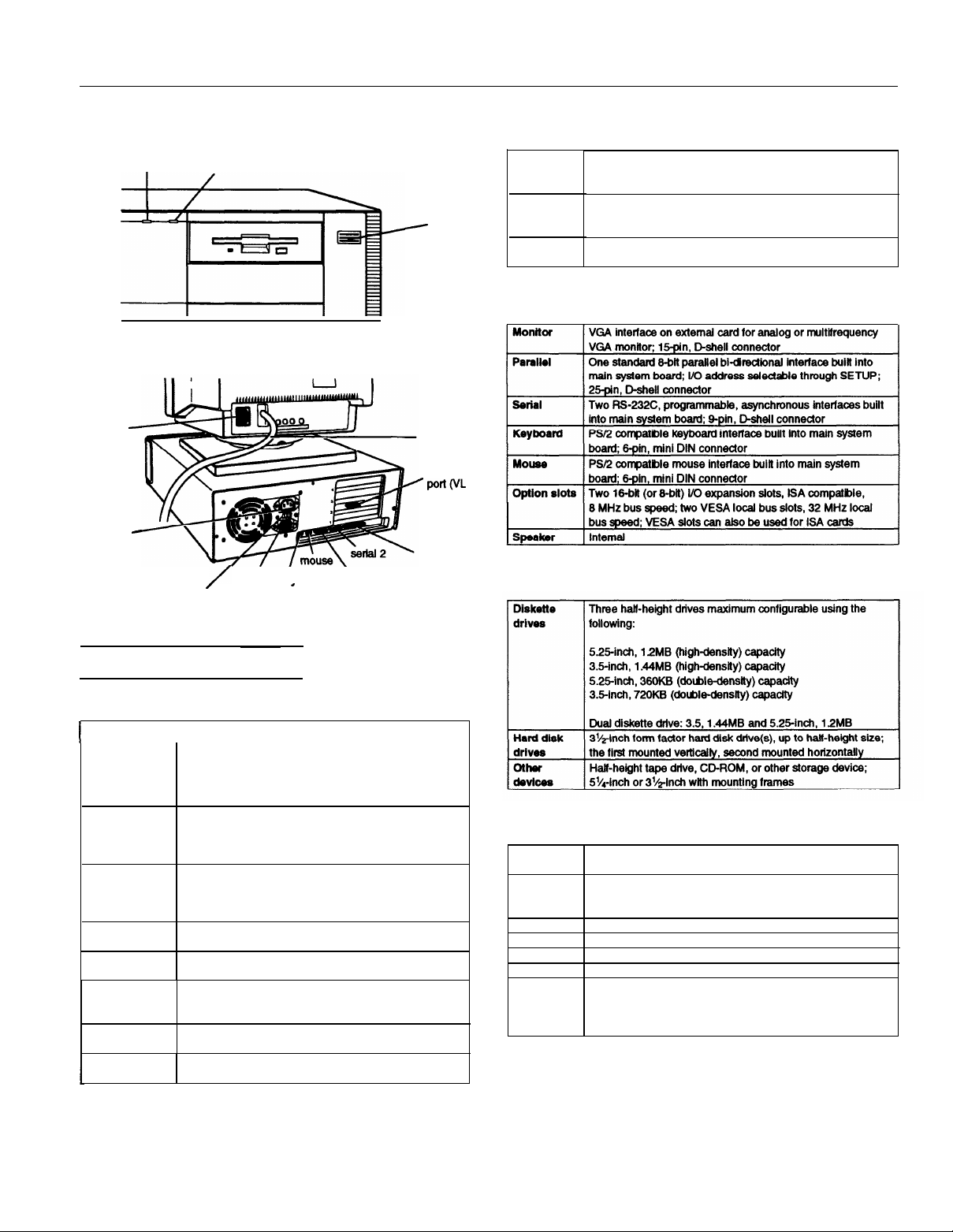
power (speed) light
AC inlet for
monitor
AC outlet
-
Controllers
I
hard disk access light
-
power
button
Video
Diskette
Hard disk
External VESA local bus video cam supports high resolution
displays (preinstailed on systems sold in the United States);
see the video card manual for more information
Controller on main system board supports up to two diskette
drives or one diskette drive and one tape drive or other
storage device
Local bus IDE interface on main system board supports up to
two IDE hard disk drives with built-in controllers.
Interfaces
monitor
cable
video
‘PofloIL
slots are
2 and 3)
-
/
/
voltage
switch
AC
inlet
keyboard
.
Serial
parallel
port
Mass Storage
Computer Specifications
CPU and Memory
32-bit
CPU
I
System speed
Memory
ROM
Shadow RAM
Cache
Math
coprocessor microprocessor
Clock/ calendar
Intel 486SX, DX, or DX2 processor
I
Ail systems can be upgraded with a faster
microprocessor, including SX2, DX4, and Pentium
OverDrive processor when available; DX4 processors
require an adapter board to regulate voltage
High and low speeds available; high speed is the speed
of the microprocesso
speed selection through keyboard command or SETUP;
0 watt state memory access at high speed
4MB RAM standard soldered on the system board;
expandable to 40MB (maximum) using 4MB or 16MB
SIMMs; SIMMs must be 32- or 36-bit, 72-pin fast-page
mode type with 70ns (or faster) access speed
128KB system BIOS, video BIOS, and SETUP code
located in EPROM on main system board
Supports shadowing of system and video BIOS ROM into
RAM
8KB of internal cache (built into the microprocessor);
sockets for 64,128, or 256KB of SRAM external cache
(optional)
On DX and DX2 systems, math coprocessor built into the
Real-time clock, calendar, and CMOS RAM socketed on
main system board with built-in battery backup
r,
low speed is simulated 8 MHz;
Keyboard
Design
Layout
Interface
Connector
Cable length 51 inches (1300 mm); coiled
Weight
Dimensions
Detachable; two-position height; NumLock and speed settings
adjustable through SETUP
101 or 102 sculpted keys; country-dependent main typewriter
keyboard; numeric/cursor control keypad; four-key cursor
control keypad; 12 function keys
PS/2-compatibie
6-pin, mini-DIN, male
3 lb (1.36kg)
17.5 inches (446 mm) wide
6.9 inches (175 mm) deep
1.5 inches (37.6 mm) high, without legs
2 inches (51 mm) high, with legs
3/94
EPSON Endeavor VL-1
Page 2

EPSON Endeavor VL
Physical Characteristics
Power Supply
--
Power Source Requirements
120 Volt power source requirements
Power supply specifications
Option slot power limits
Maximum current
For each slot
For all tour slots
+5 Volts
7 Amps
16 Amps
+12 volts -5 Volts and -12 Volts
1.5 Amps
3 Amps
Environmental Requirements
1
I I
Non-operating
0.3 Amp
0.3 Amp
240 Volt power source
requirements
EPSON Endeavor VL-2
3/94
Page 3

Major Subassemblies
EPSON Endeavor VL
option card
connector
board
SIMM sockets
I
DIP switches
I
I
3/94 EPSON Endeavor VL-3
Page 4

EPSON Endeavor VL
System Board Layout
CPU
@F=W
EPSON Endeavor VL-4
3/94
Page 5

EPSON Endeavor VL
System board components
Jumper and DIP Switch Settings
Factory set according to system CPU
External cache jumper settings
Other DIP switch settings
-
SIMM Installation
The computer comes with 4MB of memory soldered on the
system board. By installing SIMMs you can increase the
amount of memory in your computer up to 40MB.
Each of the three SIMM sockets on the main system board
can contain one 4MB or 16MB memory module. The
following table shows the possible SIMM configurations; do
not install memory in any other configuration.
SIMM configurations
SIMM 1
0 0
4MB 0
4MB 4MB
4MB
16MB
4MB
16MB 16MB 0
4MB 16MB 16MB
Standard memory on the system board
l
SIMM 2
4MB
0
16MB
SIMM 3
0
0 8MB
0
4MB
0
0
Before you install SIMMs, observe the following guidelines
to ensure that they will work properly:
Use only 32- or 36-bit, 72-pin, tin-plated, fast-page mode
Cl
SIMMs that operate at an access speed of 70ns or faster.
Be sure all the SIMMs operate at the same speed.
Your computer can use any SIMM that complies with
Q
industry standards.
Total
4MB*
12MB
16MB
20MB
I24MB
36MB
40MB
I
Factory setting; change jumpers only if external cache chips are installed at
factory or by servicer
Clock speed DIP switch settings
Clock speed*
25
MHz
33
MHz
Factory set according to system type; DX2/50 and DX2/66 systems are set at
25
and 33 MHz, respectively
Switch 1
OFF
ON
Switch 2
OFF
ON
Switch 3
ON
OFF
3/94
Supported SIMMs
EPSON Endeavor VL-5
Page 6

EPSON Endeavor VL
External Cache
You can install cache SRAM DIP chips to increase the cache
memory to 64KB, 128KB, or 256KB, depending on the
amount of cache memory installed at the factory. You must
change the settings of jumpers J4 through J7 to match the
cache memory size.
Supported
Socket
U20, U21 (15-ns)
U22 - U28 (20-ns) Alliance
cache memory
Manufacturer
Alliance
Winbond
Samsung
Micron
Winbond
UMC
Samsung
Micron -
SRAM
DIP chips
Original manufacturer part number
AS7C256-15PC
W24257AK-15
KM68257BP-15
MT5C42568-15
AS7C256-20PC
W24266(7)AK-20
UM61256-20
KM68257 BP-20
MT5C42568-15
I
Cache memory configurations
Bank 0
U22, U23, U24, U25
8Kx8
32Kx8
32Kx8
Bank 1
U26, U27, U28, U29
8Kx8
I
I32Kx8
Tag SRAM
(U20, U21) cache
8Kx8
8Kx8/32Kx8 128KB
I32Kx8
Total
[
256KB
I
Microprocessor Upgrades
Hard Disk Drive Types
The following table lists standard hard disk drive types.
Check the table and the drive manufacturer’s documentation
for the correct drive type number. If none of the types listed
matches, select Type 47 (user-defined), and enter the
appropriate numbers for the cylinders, heads, precomp,
landing zone, and sectors in SETUP.
Hard disk drive types
The computer’s processor can be upgraded by replacing the
existing microprocessor with a faster one. You can either
purchase an upgrade kit from EPSON or buy the individual
components separately, as listed in the following table.
Microprocessor upgrade components
l
For the DX/33, DX2/50, DX2/66, DX4 and Pentium OverDrive processor
You may also need to change the settings of jumper J1 or DIP
switches 1,2, and 3.
l
Actual formatted size may be slightly different than size on drive label.
EPSON Endeavor VL-6
3/94
Page 7

EPSON Endeavor VL
Drive Option Information
Hard disk drive options for 1-inch IDE drives
Diskette and magneto optical drive options
System Memory Map
40MB
Extendedmemory
l
Select 1 or none for the precomp value. If neither of these options am
available, select the maximum available precomp value.
IDE hard disk drive jumper settings
l
CS (cable selection) can be jumpered for any configuration. When CS is used,
the drive is a master if pin 26 is grounded, or a slave if pin 26 k not
grounded.
FFFF
F000
E000
D000
C800
system ROM
64KB
unused
64KB
unused
32KB
unused
Video ROM
VGA text
32KB
unused
VGA graphics
Base memory
1MB
640KB
3/94
EPSON Endeavor VL-7
Page 8

EPSON Endeavor VL
DMA Assignments
Hardware Interrupts
System I/O address map (continued)
Connector Pin Assignments
Mouse connector pin assignments (CN4)
Pin
Signal
1
Mouse data 4 +5 VDC
2
Reserved
3
Ground
Pin
5
6
Signal
Mouse clock
Reserved
System l/O Address Map
Keyboard connector pin assignments (CN5)
Pin Signal
1
Keyboard data 4 +5 VDC
2
Resewed
3
Ground
Pin
5
6
Signal
Keyboard
Resewed
data
Serial port connector pin assignments (CN9, CN10)
Parallel port connector pin assignments (CN11)
EPSON Endeavor VL-8
3/94
Page 9

EPSON Endeavor VL
Power connector pin assignments (CN1)
Diskette drive connector pin assignments (CN12)
Hard disk drive connector pin assignments (CN13)
SIMM connector pin assignments (SMM1-SIMM3)
* Active low logic
Option card riser board connector pin assignments (CN16)
Hard disk drive LED connector pin assignments (CN14)
1
2
3 HDD
4
VCC
HDD
VCC
Speed indicator LED connector pin assignments (CN6)
Pin Signal
1
2
3
VCC
TURBO
Ground
Speaker connector pin assignments (CN15)
Pin Signal
1
3
4
VCC
I
Ground
ISPKD
3/94
EPSON Endeavor VL-9
Page 10

EPSON Endeavor VL
VESA expansion slot pin assignments
VL-bus slot connector pin assignments
Option Card Riser Board
The option card riser board contains four ISA option card
slots and two VL,-bus slots
The A side of the connector is the component side of the
option card; the B side is the solder side of the option card.
EPSON Endeavor VL-10 3/94
Page 11

EPSON Endeavor VL
Installation/Support Tips
Installing Diskette Drives
Make sure that the drive type has been correctly selected in
the SETUP program.
Installing Hard Disk Drives
When installing a hard disk drive, see the hard disk drive
Ll
type table to select the correct type number for the drive.
If the parameters for your drive are not listed, you can
define your own drive type by selecting drive type 47 and
entering the drive’s exact parameters for this userdefined
drive type.
Cl
It is recommended that a 16-bit, AT-type hard disk
controller be used if you are installing a drive that cannot
use the embedded IDE interface. If you install a non-IDE
hard disk drive and controller card, use the SETUP
program to disable the built-in IDE hard disk drive
interface.
Software Problems
Ll
When installing a copy-protected software package, first
try the installation at high speed. If this does not work
properly, select low speed by pressing Ctrl Alt - . Try
loading the program at low speed and then switching to
high speed, if possible.
Cl When using a software package that uses a key disk as its
copy-protection method, try loading it at high speed. If
this does not work, load it at low speed.
Information Reference List
Engineering Change Notices
None.
Technical Information Bulletins
None.
Product Support Bulletins
None.
Related Documentation
TM-ENDVRVL
PL-ENDVRVL
400305700 EPSON Endeavor VL User’s Guide
EPSON Endeavor VL Service Manual
EPSON Endeavor VL Parts Price List
Booting Sequence
If you cannot boot the computer from the hard disk, make
sure the booting sequence in SETUP is set to
Then boot the computer from a system diskette in drive A.
then C : .
A:
Password
Make sure that you do not forget the password you set up. If
you do:
Disable the password by setting DIP switch 4 on the main
1.
system board to ON.
Then turn the computer on, wait 20 seconds, and turn it
2.
off again.
3.
Set DIP switch 4 to OFF to enable the password function.
4.
Run SETUP to enter a new password, if desired.
You can also enter a hot key designation in SETUP to secure
the system from unauthorized users. Once a password and
hot key have been set, when the hot key is pressed, the
keyboard and mouse lock until the user enters the password.
3/94
EPSON Endeavor VL-11
 Loading...