

Page 1
INSTALLATION GUIDE
1
Page 2

Contents
1.Safety Instructions . . . . . . . . . . . . . . . . . . . . . . . . . . . . . . . . . . . . . . . . . . . . . . . . . .5
2.Installation . . . . . . . . . . . . . . . . . . . . . . . . . . . . . . . . . . . . . . . . . . . . . . . . . . . . . . . .7
2-1.Projection distance between projector and screen . . . . . . . . . . . . . . . . . . . . . .7
2-1-1.When using the standard lens . . . . . . . . . . . . . . . . . . . . . . . . . . . . . . . . . .7
<Model EMP-8000> . . . . . . . . . . . . . . . . . . . . . . . . . . . . . . . . . . . . . . . . .8
2-1-2.When using the long zoom lens ELPLL02 (optional) . . . . . . . . . . . . . . . .9
2-1-3.When using the long zoom lens ELPLL01 (optional) . . . . . . . . . . . . . . .10
Attaching the LONG THROW ZOOM LENS . . . . . . . . . . . . . . . . . . . . . .11
2-1-4.When using the wide conversion lens (ELPCW01) . . . . . . . . . . . . . . . . .16
2-1-5.When using the wide zoom lens ELPLW01 (optional) . . . . . . . . . . . . . . .17
2-2.Cabling . . . . . . . . . . . . . . . . . . . . . . . . . . . . . . . . . . . . . . . . . . . . . . . . . . . . . . .20
2-2-1.Connecting to a computer . . . . . . . . . . . . . . . . . . . . . . . . . . . . . . . . . . . .20
• Projecting the computer image . . . . . . . . . . . . . . . . . . . . . . . . . . . . . . .20
<Connecting two computers> . . . . . . . . . . . . . . . . . . . . . . . . . . . . . . . . . .21
<Projecting the projector image on a monitor display> . . . . . . . . . . . . . .22
<Outputting the computer voice from the projector> . . . . . . . . . . . . . . . .23
<Connecting a computer directly to external audio equipment> . . . . . . .23
<Outputting the computer voice input to the projector from external
audio equipment> . . .24
<Connecting to a workstation> . . . . . . . . . . . . . . . . . . . . . . . . . . . . . . . . .25
<If the workstation is a 5BNC port (1):> . . . . . . . . . . . . . . . . . . . . . . . . . 26
<If the workstation is a 5BNC port (2):> . . . . . . . . . . . . . . . . . . . . . . . . . .26
2-2-2.Connecting to a video source . . . . . . . . . . . . . . . . . . . . . . . . . . . . . . . . .27
• Inputting the composite video signal . . . . . . . . . . . . . . . . . . . . . . . . . . .27
• Inputting the S-Video signal . . . . . . . . . . . . . . . . . . . . . . . . . . . . . . . . . .27
• Inputting the component (color-difference) video signal . . . . . . . . . . . .28
• Inputting the composite video signal . . . . . . . . . . . . . . . . . . . . . . . . . . .29
• Inputting the S-Video signal . . . . . . . . . . . . . . . . . . . . . . . . . . . . . . . . . .29
• Inputting the component (color-difference) video signal . . . . . . . . . . . .30
• Setting the BNC terminal entry mode . . . . . . . . . . . . . . . . . . . . . . . . . .31
2-3.Mounting Position and Location . . . . . . . . . . . . . . . . . . . . . . . . . . . . . . . . . . . .32
2-3-1.Positioning the projector and screen . . . . . . . . . . . . . . . . . . . . . . . . . . . .32
• Positioning the projector and screen . . . . . . . . . . . . . . . . . . . . . . . . . . .32
2-3-2.Assembly and Mounting . . . . . . . . . . . . . . . . . . . . . . . . . . . . . . . . . . . . .33
• Projector Mounting . . . . . . . . . . . . . . . . . . . . . . . . . . . . . . . . . . . . . . . . .33
• Installing on the Ceiling . . . . . . . . . . . . . . . . . . . . . . . . . . . . . . . . . . . . .33
2-3-3.Adjustment Function . . . . . . . . . . . . . . . . . . . . . . . . . . . . . . . . . . . . . . . .34
2-3-4.Example of mounting to ceiling . . . . . . . . . . . . . . . . . . . . . . . . . . . . . . . .35
• For concrete ceilings . . . . . . . . . . . . . . . . . . . . . . . . . . . . . . . . . . . . . . .35
2-3-5.Ceiling Plate and Pipe Configurations . . . . . . . . . . . . . . . . . . . . . . . . . . .36
• Ceiling plate configuration . . . . . . . . . . . . . . . . . . . . . . . . . . . . . . . . . . .36
• Pipe configurations . . . . . . . . . . . . . . . . . . . . . . . . . . . . . . . . . . . . . . . .36
• Securing the Ceiling Plate to the Ceiling . . . . . . . . . . . . . . . . . . . . . . . .37
• Installing the Pipe . . . . . . . . . . . . . . . . . . . . . . . . . . . . . . . . . . . . . . . . .37
• Installing to the Ceiling . . . . . . . . . . . . . . . . . . . . . . . . . . . . . . . . . . . . . .37
2-3-6.Using the ceiling mounting bracket fixture and pipe . . . . . . . . . . . . . . . .39
• Installing the Flange . . . . . . . . . . . . . . . . . . . . . . . . . . . . . . . . . . . . . . . .39
2
Page 3

2-3-7.Adjustment Function . . . . . . . . . . . . . . . . . . . . . . . . . . . . . . . . . . . . . . . .42
• Using the ceiling-hung projector . . . . . . . . . . . . . . . . . . . . . . . . . . . . . .43
• Projecting the image from the behind of the screen
using the ceiling-hung projector . . . . . . . .44
2-3-8.Checking that the projector is operational . . . . . . . . . . . . . . . . . . . . . . . .45
3.Installing the stack multi-screen(Model EMP-8000 only) . . . . . . . . . . . . . . . . . . . .46
3-1.The following tips should be kept in mind when you install the
stack multi-screen: . . . . . . . .46
3-2.Connection for stack projection of the computer image . . . . . . . . . . . . . . . . . .47
3-2-1.If the computer has a 15-pin micro-D-style (BNC) output port . . . . . . . .47
3-2-2.Adjustment before stack projection . . . . . . . . . . . . . . . . . . . . . . . . . . . . .49
<Adjusting the color with the test pattern> . . . . . . . . . . . . . . . . . . . . . . . .49
• For Windows users: . . . . . . . . . . . . . . . . . . . . . . . . . . . . . . . . . . . . . . . .49
• Using the lens shift function . . . . . . . . . . . . . . . . . . . . . . . . . . . . . . . . . .50
• Color setting . . . . . . . . . . . . . . . . . . . . . . . . . . . . . . . . . . . . . . . . . . . . . .51
3-3.Operating/controlling the stack-connected projectors . . . . . . . . . . . . . . . . . . .52
3-3-1.Establishing the stack-connection . . . . . . . . . . . . . . . . . . . . . . . . . . . . . .52
• For Macintosh users: . . . . . . . . . . . . . . . . . . . . . . . . . . . . . . . . . . . . . . .52
3-3-2.Operating the stack-connected projectors . . . . . . . . . . . . . . . . . . . . . . .56
• Turn on all projectors at a time . . . . . . . . . . . . . . . . . . . . . . . . . . . . . . .56
3-3-3.Alert message on the Installer specific setting window . . . . . . . . . . . . . .56
3-3-4.Using the setting menu . . . . . . . . . . . . . . . . . . . . . . . . . . . . . . . . . . . . . .57
• For Windows users: . . . . . . . . . . . . . . . . . . . . . . . . . . . . . . . . . . . . . . . .57
• For Macintosh users: . . . . . . . . . . . . . . . . . . . . . . . . . . . . . . . . . . . . . . .58
3-3-5.Operations and restrictions on the stack-connection . . . . . . . . . . . . . . .60
• Operations . . . . . . . . . . . . . . . . . . . . . . . . . . . . . . . . . . . . . . . . . . . . . . .60
4.Installing the remote control receiver . . . . . . . . . . . . . . . . . . . . . . . . . . . . . . . . . . .61
4-1.Installing . . . . . . . . . . . . . . . . . . . . . . . . . . . . . . . . . . . . . . . . . . . . . . . . . . . . . .61
5.Maintenance . . . . . . . . . . . . . . . . . . . . . . . . . . . . . . . . . . . . . . . . . . . . . . . . . . . . . .62
5-1.Replacing the lamp . . . . . . . . . . . . . . . . . . . . . . . . . . . . . . . . . . . . . . . . . . . . .63
5-1-1.Model EMP-7350/EMP-7250/EMP-5350 . . . . . . . . . . . . . . . . . . . . . . . .63
5-1-2.Model EMP-8000 . . . . . . . . . . . . . . . . . . . . . . . . . . . . . . . . . . . . . . . . . .65
5-2.Replacing the air filter . . . . . . . . . . . . . . . . . . . . . . . . . . . . . . . . . . . . . . . . . . .67
5-2-1.Model EMP-7350/EMP-7250/EMP-5350 . . . . . . . . . . . . . . . . . . . . . . . .67
5-2-2.Model EMP-8000 . . . . . . . . . . . . . . . . . . . . . . . . . . . . . . . . . . . . . . . . . .68
6.Product specifications . . . . . . . . . . . . . . . . . . . . . . . . . . . . . . . . . . . . . . . . . . . . . .69
6-1.Projector specifications . . . . . . . . . . . . . . . . . . . . . . . . . . . . . . . . . . . . . . . . . .69
6-1-1.Model EMP-7350/EMP-7250/EMP-5350 . . . . . . . . . . . . . . . . . . . . . . . .69
6-1-2.Model EMP-8000 . . . . . . . . . . . . . . . . . . . . . . . . . . . . . . . . . . . . . . . . . .70
6-2.Lens specifications . . . . . . . . . . . . . . . . . . . . . . . . . . . . . . . . . . . . . . . . . . . . . .71
6-2-1.Long zoom lens (ELPLL02) . . . . . . . . . . . . . . . . . . . . . . . . . . . . . . . . . . .71
6-2-2.Wide conversion lens (ELPCW01) . . . . . . . . . . . . . . . . . . . . . . . . . . . . .71
6-3.Using the control panel on the projector . . . . . . . . . . . . . . . . . . . . . . . . . . . . .72
6-3-1.Model EMP-7350/EMP-7250/EMP-5350 . . . . . . . . . . . . . . . . . . . . . . . .72
6-3-2.Model EMP-8000 . . . . . . . . . . . . . . . . . . . . . . . . . . . . . . . . . . . . . . . . . .74
6-4.Using the remote control . . . . . . . . . . . . . . . . . . . . . . . . . . . . . . . . . . . . . . . . .76
3
Page 4

6-4-1.Front . . . . . . . . . . . . . . . . . . . . . . . . . . . . . . . . . . . . . . . . . . . . . . . . . . . .76
6-4-2.Inside of the cover . . . . . . . . . . . . . . . . . . . . . . . . . . . . . . . . . . . . . . . . . .77
6-5.I/O terminals . . . . . . . . . . . . . . . . . . . . . . . . . . . . . . . . . . . . . . . . . . . . . . . . . . .78
6-5-1.Model EMP-7350/EMP-7250/EMP-5350 . . . . . . . . . . . . . . . . . . . . . . . .78
6-5-2.Model EMP-8000 . . . . . . . . . . . . . . . . . . . . . . . . . . . . . . . . . . . . . . . . . .80
6-6.Dimensional diagram . . . . . . . . . . . . . . . . . . . . . . . . . . . . . . . . . . . . . . . . . . . .82
6-6-1.Projector<Model EMP-8000> . . . . . . . . . . . . . . . . . . . . . . . . . . . . . . . . .82
6-6-2.I/O panel . . . . . . . . . . . . . . . . . . . . . . . . . . . . . . . . . . . . . . . . . . . . . . . . .84
6-7.Connector pin assignments . . . . . . . . . . . . . . . . . . . . . . . . . . . . . . . . . . . . . . .85
6-7-1.Computer1/2 In . . . . . . . . . . . . . . . . . . . . . . . . . . . . . . . . . . . . . . . . . . . .85
6-7-2.Audio1 In . . . . . . . . . . . . . . . . . . . . . . . . . . . . . . . . . . . . . . . . . . . . . . . . .85
6-7-3.Audio Out . . . . . . . . . . . . . . . . . . . . . . . . . . . . . . . . . . . . . . . . . . . . . . . .86
6-7-4.Computer Out(Model EMP-800:Monitor Out) . . . . . . . . . . . . . . . . . . . . .86
6-7-5.S-Video In . . . . . . . . . . . . . . . . . . . . . . . . . . . . . . . . . . . . . . . . . . . . . . . .87
6-7-6.L-Audio-R . . . . . . . . . . . . . . . . . . . . . . . . . . . . . . . . . . . . . . . . . . . . . . . .87
6-7-7.L-Audio2-R . . . . . . . . . . . . . . . . . . . . . . . . . . . . . . . . . . . . . . . . . . . . . . .87
6-7-8.Video . . . . . . . . . . . . . . . . . . . . . . . . . . . . . . . . . . . . . . . . . . . . . . . . . . . .87
6-7-9.Mouse/Com . . . . . . . . . . . . . . . . . . . . . . . . . . . . . . . . . . . . . . . . . . . . . . .88
6-7-10.Remote . . . . . . . . . . . . . . . . . . . . . . . . . . . . . . . . . . . . . . . . . . . . . . . . .88
6-8.Main cable . . . . . . . . . . . . . . . . . . . . . . . . . . . . . . . . . . . . . . . . . . . . . . . . . . . .89
4
Page 5

1.Safety Instructions
Warning
• The installation procedure described in this manual is written for your dealer with who has the
adequate know-how and skill to install the projector.
• In the following situations turn off the projector, and unplug it from the wall outlet.
• If smoke is detected, or if an unusual smell or noise is present.
• If the projector does not work properly due to a failure including no image and no sound on the
screen.
• If liquid or foreign matter has been entered into the projector.
• If the projector has been dropped or the housing has been damaged.
Failure to do so may result in fire or electric shock.
• Never open the cabinet of the projector except for your dealer or qualified service personnel. Do
not disassemble or modify the projector under any circumstances.
Dangerous electrical voltages inside the projector can cause fire, electric shock, or injury.
• Use the type of power source indicated on the projector.
Failure to do so may result in fire or electric shock.
• Use the power cable supplied with the projector.
Failure to do so may result in fire or electric shock.
• Do not use the damaged power cable.
Failure to do so may result in fire or electric shock.
Always take the following precautions when handling the power cable.
• Do not work on the power cable.
• Do not place a heavy object on the power cable.
• Do not bend, twist or pull the power cable by forcing.
• Do not lay the power cable near a heater.
Replace the damaged power cable with the new one.
• Never look into the projector lens when the lamp is switched on.
The bright light can damage your eyes.
• Extra special care must be taken on handling the power plug/power connector. Failure to do so
may result in fire or electric shock.
Always take the following precautions when handling the power plug/power connector.
• Avoid the star-burst connection.
• Ensure that the power plug/power connector is free of dust before inserting it into a socket.
• Ensure that the power plug/power connector is inserted into the socket securely.
• Do not insert or disconnect the power plug/power connector with wet hands.
• Do not pull the power cable to disconnect the power plug/power connector. Always disconnect
the power plug holding the plug or connector itself.
• A lot of glass components such as a lens and lamp are employed in the projector.
If any of the components is broken, handle it so you do not cut yourself. Refer all servicing to the
EPSON Service Center.
• Do not place a vase, container filled with water, or chemicals on the projector.
Failure to do so may result in fire or electric shock due to spillover or entry of water or chemicals.
• Do not insert or drop objects of any kind including a metal, flammable material, and foreign
matter into the openings such as the vent hole on the projector.
Failure to do so may result in fire or electric shock.
• Do not place the projector or remote control with batteries inserted in an extremely heated place,
such as a car with all windows closed, an area exposed to direct sunlight, and an air flap of an air
conditioner/heater.
It may result in deformation due to heat, or the adverse effect on the components inside the
projector which may lead to fire.
• Do not step on the projector or place a heavy object on it.
5
Page 6

Failure to do so may result in injury due to falling or breakage.
• Do not place the projector on an unstable place such as a wobbly or inclined stand.
Failure to do so may result in injury due to dropping or breakage.
• Install or keep the projector out of the reach of children.
Failure to do so may result in injury due to dropping or breakage.
• Do not place the projector on a humid or dusty place, or near a place with greasy fumes/steam
given off such as a cookware or humidifier.
Failure to do so may result in fire or electric shock.
• Do not block the intake fan/exhaust fan on the projector. They provide ventilation and prevent
the projector from overheating which may lead to fire. Do not place the projector in a place as
follows:
• In an enclosed area such as a closet and bookcase.
• On a rug, bedding or blanket.
• Do not cover a cloth such as a blanket, curtain and tablecloth over the projector.
Keep the clearance of 20 cm or more between the wall and the projector if wall-mounted.
• Turn off the projector, unplug it from the wall outlet, and ensure that all cabling is disconnected
before moving the projector.
Failure to do so may result in fire or electric shock.
• Never remove the lamp immediately after turning off the projector.
• Failure to do so may result in burns or injury due to heat.
Let the projector cool for about 60 minutes after turning off it. Ensure that the projector is
sufficiently cooled down before replacing the lamp.
• Misuse of a battery can result in fire, injury, or corrosion on the projector due to explosion or
liquid leakage. Always take the following precautions when using a battery safely.
• Do not use batteries different in kind or old and new batteries together.
• Always use the type of battery indicated in the instruction manual.
• Wipe off liquid leaked from a battery with a cloth, and replace it with the new one.
• Replace a dead battery with the new one immediately.
• Remove batteries if you will not use the projector for an extended time.
• Do not heat s battery or dispose of it in fire or water.
• Check the polarity (+, -) before inserting a battery.
• Wash your hands immediately if leaked liquid has contacted to them.
Dispose of an old battery following the local regulations.
• Disconnect the power plug/power connector from the wall outlet before cleaning.
Failure to do so may result in electric shock.
6
Page 7
2.Installation
2-1.Projection distance between projector and screen
First of all, determine the projection distance between the projector and the screen. Then, place
the projector the correct distance from the screen.
2-1-1.When using the standard lens
<Model EMP-7350/EMP-7250/EMP-5350>
• Adjust the distance between the projector lens and screen so that the desired image size is
obtained.
• The projectors that can be mounted with this bracket are equipped with 1.3X zoom lenses.
Thus, the maximum enlargement of the projected image size is 1.3 times the minimum
enlargement. The relationship between projection distance and screen size is as shown in the
table below. Ideal images are obtained with a projection distance of from 1.6m to 16.7m.
* If a screen size other than those shown above is used, determine the correct distance between
Approximate
Scrrin size (cm)
Projector Distace
(m)
300inch(610x457) 12.4-16.7 437.0 23.0
200inch(406x305) 8.3-11.1 285.0 15.0
100inch(203x152) 4.1-5.5 142.5 7.5
80inch(163x122) 3.3-4.4 114.0 6.0
60inch(122x91) 2.5-3.3 85.5 4.5
40inch(81x61) 1.6-2.1 58.0 3.1
30inch(61x46) 1.6 43.7 2.3
the projector and the screen according to the following expression.
Maximum screen size(cm)=0.612 X Projector to screen(cm) + 3.877
Minmun screen size(cm)=0.456 X Projector to screen(cm) + 2.898
Maximun Projector to screen(cm) =2.195 X screen size(cm) - 6.361
Minmun Projector to screen(cm) =1.633 X screen size(cm) - 6.330
A
Dimension A
(see fig. below)
(cm)
12.4-16.7
8.3-11.1
4.1-5.5
3.3-4.4
2.5-2.2
1.6-2.1
1.6
Dimension B
(see fig. below)
Screen Size
(cm)
300inch
200inch
100inch
80inch
60inch
40inch
30inch
Center of lens
B
Distance from the projector (m)
A:B will be 19:1
7
Page 8
<Model EMP-8000/EMP-9000>
A
B
• Adjust the distance between the projector lens and screen so that the desired image size is
obtained.
• The projectors that can be mounted with this bracket are equipped with 1.4X zoom lenses.
Thus, the maximum enlargement of the projected image size is 1.4 times the minimum
enlargement. The relationship between projection distance and screen size is as shown in the
table below. Ideal images are obtained with a projection distance of from 1.1m to 15.6m.
Scrrin size (cm)
Approximate
Projector Distace
(m)
Dimension A
(see fig. below)
(cm)
Dimension B
(see fig. below)
(cm)
300inch(610x457) 11.2-15.6 460 230
200inch(406x305) 7.5-10.4 300 150
100inch(203x152) 3.7-5.1 150 75
80inch(163x122) 3.0-4.1 120 60
60inch(122x91) 2.2-3.0 90 45
40inch(81x61) 1.5-2.0 61 30.5
30inch(61x46) 1.1-1.4 46 23
* If a screen size other than those shown above is used, determine the correct distance between
the projector and the screen according to the following expression.
Maximum screen size(cm)=0.676 X Projector to screen(cm) + 5.824
Minmun screen size(cm)=0.483 X Projector to screen(cm) + 4.163
Maximun Projector to screen(cm) =2.070 X screen size(cm) - 1.334
Minmun Projector to screen(cm) =1.480 X screen size(cm) - 1.334
10:1
11.2-15.6
7.5-10.4
3.7-5.1
3.0-4.1
2.2-3.0
1.5-2.0
1.1-1.4
300inch
200inch
100inch
80inch
60inch
40inch
30inch
Screen Size
Center of lens
Distance from the projector (m)
5:5
11.2-15.6
7.5-10.4
3.7-5.1
3.0-4.1
2.2-3.0
1.5-2.0
1.1-1.4
300inch
200inch
100inch
80inch
60inch
40inch
30inch
Screen Size
Center of lens
Distance from the projector (m)
8
Page 9
2-1-2.When using the long zoom lens ELPLL02 (optional) <ELP-8000>
The screen image in the maximum zoom in mode is projected at a size 1.7 times larger than
that in the minimum zoom in mode as an 1.7:1 zoom lens is fitted as optional.
We recommend that the projection distance between the projector and the screen is set to 4.1 m to
17.6 m at installation. The following table shows the guidelines to adjust to the correct distance.
The remote control supplied with the projector offers the remote operation up to 10 m from the
projector. If you want to operate the projector at a distance of 10 m or more from it, it is necessary
to install and use the optional remote control receiver ELPST02.
Scrrin size (cm) Approximate Projector Distace (m)
Wide Tele
300inch(610x457) 15.6 200inch(406x305) 10.4 17.6
100inch(203x152) 5.1 8.7
80inch(163x122) 4.1 6.9
60inch(122x91) - 5.1
* If a screen size other than those shown above is used, determine the correct distance between
the projector and the screen according to the following expression.
Maximum screen size(cm)=0.487 X Projector to screen(cm) + 5.933
Minmun screen size(cm)=0.286 X Projector to screen(cm) + 3.703
Maximun Projector to screen(cm) =3.492 X screen size(cm) - 2.004
Minmun Projector to screen(cm) =2.053 X screen size(cm) - 1.888
9
Page 10
2-1-3.When using the long zoom lens ELPLL01 (optional)
<Model EMP-7350/7250/5350>
The screen image in the maximum zoom in mode is projected at a size 1.7 times larger than
that in the minimum zoom in mode as an 1.7:1 zoom lens is fitted as optional.
We recommend that the projection distance between the projector and the screen is set to 1.9 m to
25.8 m at installation. The following table shows the guidelines to adjust to the correct distance.
The remote control supplied with the projector offers the remote operation up to 10 m from the
projector. If you want to operate the projector at a distance of 10 m or more from it, it is necessary
to install and use the optional remote control receiver ELPST02.
Scrrin size (cm) Approximate Projector Distace (m)
Wide Tele
300inch(610x457) 15.4 25.8
200inch(416x305) 10.5 17.5
100inch(203x152) 5.1 8.7
80inch(163x122) 4.0 6.8
60inch(122x91) 3.0 5.1
40inch(81x61) 1.9 3.3
* If a screen size other than those shown above is used, determine the correct distance between
the projector and the screen according to the following expression.
Maximum screen size(cm)=0.474 X Projector to screen(cm) + 8.252
Minmun screen size(cm)=0.285 X Projector to screen(cm) + 4.818
Maximun Projector to screen(cm) =3.509 X screen size(cm) - 16.908
Minmun Projector to screen(cm) =2.109 X screen size(cm) - 17.404
10
Page 11
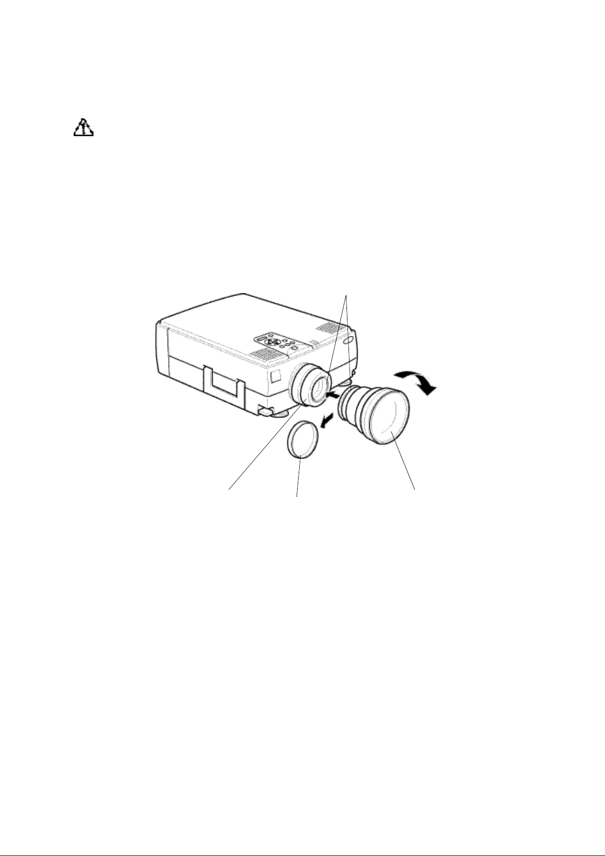
• Attaching the LONG THROW ZOOM LENS
Warning
• The lens is sold under the condition that it is attached by a dealer with sufficient skill and
technical ability.
• Tighten the screws securely.
• Incorrect attachment of the lens may result in it falling and causing accidents if the projector is
suspended.
Memo
• Always attach or remove the lenses in a clean dust-free room. Dust inside the projector can
cause malfunctions.
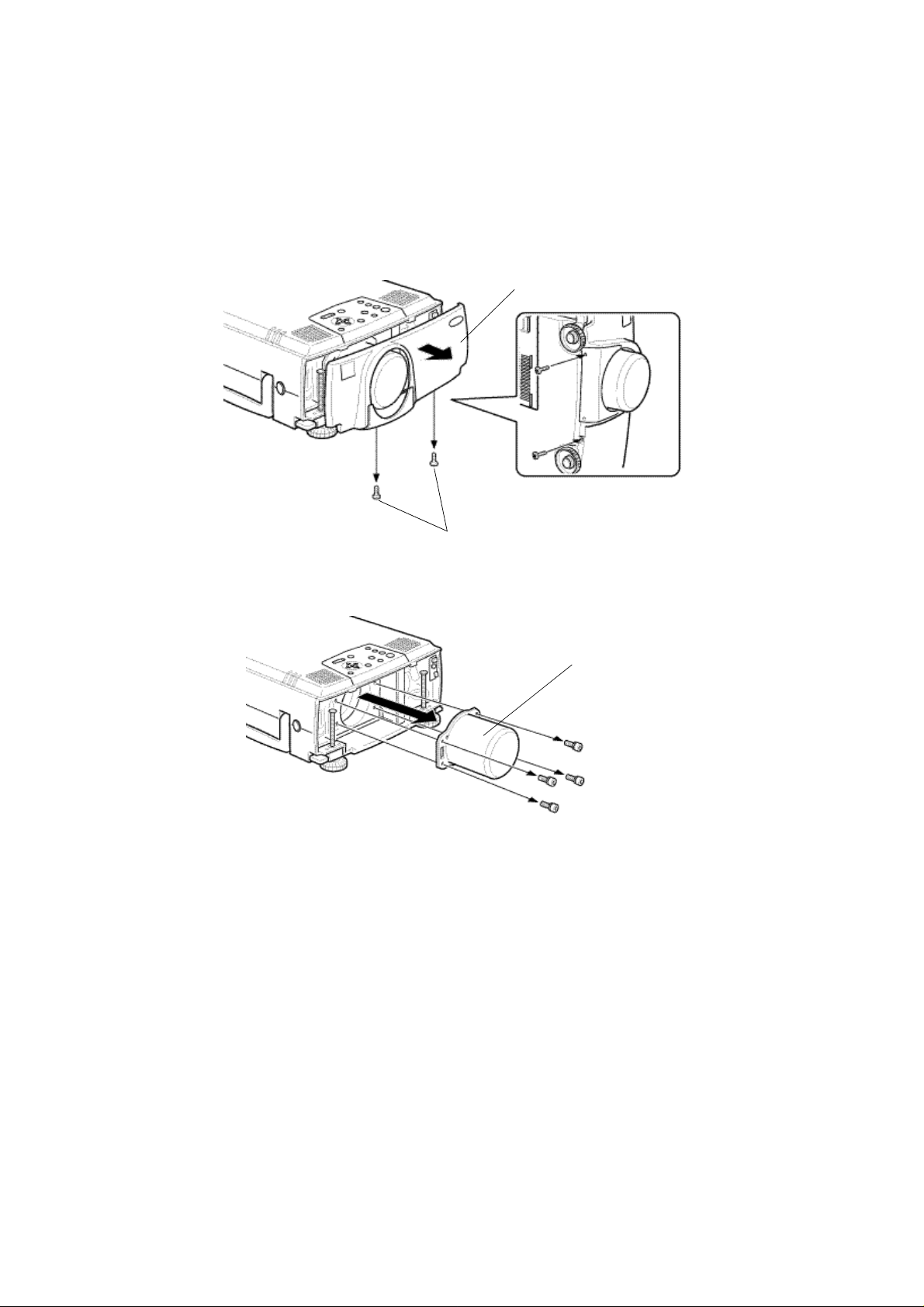
<Model EMP-7350/EMP-7250/EMP-5350>
(1)Remove the rear interface panel.
• Remove the four screws and detach the interface panel.
Interface pane
(2)Remove the front case screws.
• Remove five screws: two each side and one at the rear.
• Remove two screws: one at the handle and one at the bottom.
Front case
Handle
11
Page 12
(3)Remove the operating panel lead circuit board and front case.
• Raise the front case gently to a position where the lead circuit board’s
connections can be checked.
• Release the connector lock and remove the lead circuit board.
• Remove the front case.
lead circuit board
Connector
Release lock
Memo
Be sure to remove the front case only after releasing the lead circuit board lock. Otherwise, you
may damage the load cicuit board and connector.
(4)Remove the speaker unit at the left (facing to the lens).
• Remove a screw of the fixing plate for attaching the speaker unit.
• Gently lift up the speaker unit until the four screws fixing the lens can be seen.
Speaker unit
Fixing plate
Memo
When moving the speaker unit, be sure to not break the wire.
12
Page 13
(5)Removing the standard lens.
• Use the supplied screwdriver to remove the four screws, then detach the lens.
(7)Attach the LONG THROW ZOOM LENS
• Remove the lens cover attached to the lens mounting face.
• Use the supplied screwdriver to fix the lens in proper place with the four screws.
Mount the lens with the seal top.
Seal
Lens cover
Memo
When re-attaching the standard lens, make sure that the seal appears on the top.
(8)Assembly
Reverse the removal procedure to attach the lens.
• Attach the speaker unit
• Insert the lead circuit board into the operating panel connector and lock it.
• Attach the front case and fasten it with the screws
• Attach the interface panel and fasten it with the screws.
Assembly is now complete.
• Turn on the power to check that the projector is operating normally.
Memo
To prevent melting of the lens cap, always remove the lens cap while the power is turned on.
13
Page 14
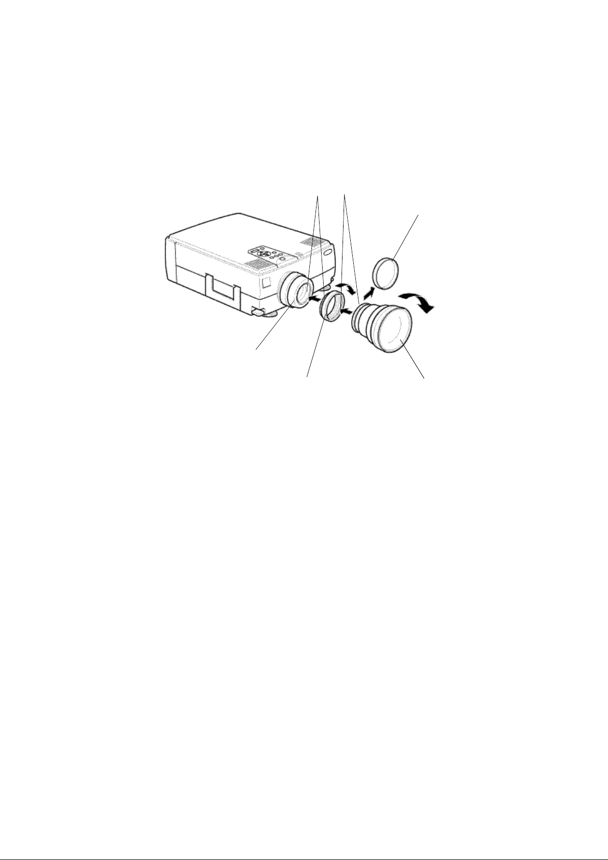
<Model EMP-8000>
(1)Remove the rear interface panel.
• Remove the tow screws and detach the interface panel.
Memo
Choose a Phillips screwdriver which suits the screws.
Front case
screws
(2) Unscrew the four screws to remove the existing lens using a hexagon head
screwdriver supplied with the long zoom lens.
Existing lens
14
Page 15
(3) Remove the rear lens cap on the long zoom lens.
(4) Install the long zoom lens with the four screws using a hexago head screwdriver
supplied with it.
Ensure that the arrow of the "UPPER" mark on the seal is placed up.
seal
Rear lens cap
(5) Set the front case, and secure it with two screws.
screws
screws
(6) After replacing the lens is completed, checking that the projector operates properly
as referring to the section "Checking that the projector is operational" .
15
Page 16
2-1-4.When using the wide conversion lens (ELPCW01)
The wide conversion lens can be used by fitting it to the standard lens.
The projection distance when this lens is used is shorter than when the standard lens is used.
We recommend that the projection distance between the projector and the screen is set to 0.9 m to
12.6m at installation. The following table shows the guidelines to adjust to the correct distance.
Scrrin size (cm)
300inch(610x457) 9.5-12.6
200inch(416x305) 6.3-8.4
100inch(203x152) 3.1-4.2
80inch(163x122) 2.5-3.3
60inch(122x91) 1.9-2.5
40inch(81x61) 1.2-1.6
30inch(61x41) 0.9-1.1
23inch(47x35) 0.9
* If a screen size other than those shown above is used, determine the correct distance between
the projector and the screen according to the following expression.
Maximum screen size(cm)=0.795 X Projector to screen(cm) + 6.670
Minmun screen size(cm)=0.600 X Projector to screen(cm) + 4.437
Maximun Projector to screen(cm) =1.666 X screen size(cm) - 1.145
Minmun Projector to screen(cm) =1.258 X screen size(cm) - 1.300
Approximate Projector Distace (m)
EMP-7350/7250/5350
16
Page 17
2-1-5.When using the wide zoom lens ELPLW01 (optional) <ELP-8000/ELP-9000>
The screen image in the maximum zoom in mode is projected at a size 1.2 times larger than
that in the minimum zoom in mode as an 1.2:1 zoom lens is fitted as optional.
We recommend that the projection distance between the projector and the screen is set to 1.7 m to
6.8 m at installation. The following table shows the guidelines to adjust to the correct distance.
Dimension A
Scrrin size (cm) Approximate Projector Distace (m)
(see fig. below)
(cm)
Wide Tele
200inch(406x305) 10.4 17.6 0-153
100inch(203x152) 5.1 8.7 0-76
80inch(163x122) 4.1 6.9 0-61
60inch(122x91) - 5.1 0-46
* If a screen size other than those shown above is used, determine the correct distance between
the projector and the screen according to the following expression.
Maximum screen size(cm)=0.876 X Projector to screen(cm) + 9.634
Minmun screen size(cm)=0.730 X Projector to screen(cm) + 7.694
Maximun Projector to screen(cm) =1.142 X screen size(cm) - 1.705
Minmun Projector to screen(cm) =1.369 X screen size(cm) - 1.633
5.7-6.8
2.8-3.3
2.3-2.6
1.7-1.9
Center of lens
A
Screen Size
200inch
100inch
80inch
60inch
17
Page 18
<Model EMP-7350/7250, PowerLite 7350/7250>
Warning
• Be sure to screw the wide conversion lens and adapter ring down completely. Unless they are
securely screwed on, they could fall off and cause damage or injury (especially when the
projector is ceiling-mounted).
(1)Remove the rear lens cap.
(2)Screw the wide conversion lens into the standard lens.
(3)Rotate it in the direction of the arrow below until it is secure.
Screw in tightly
Standard lens
Rear lens cap
Wide conversion lens
18
Page 19
<Model EMP-5350, PowerLite 5350>
(1)Screw the adapter ring into the standard lens.
(2)Rotate the adapter ring in the direction of the arrow below until it is secure.
(3)Remove the rear lens cap from the wide conversion lens.
(4)Screw the wide conversion lens into the adapter ring.
(5)Rotate it in the direction of the arrow below until it is secure.
Screw in tightly.
Rear lens cap
Standard lens
Adapter ring
Wide conversion lens
19
Page 20
2-2.Cabling
2-2-1.Connecting to a computer
<Model EMP-7350/EMP-5350/EMP-8000>
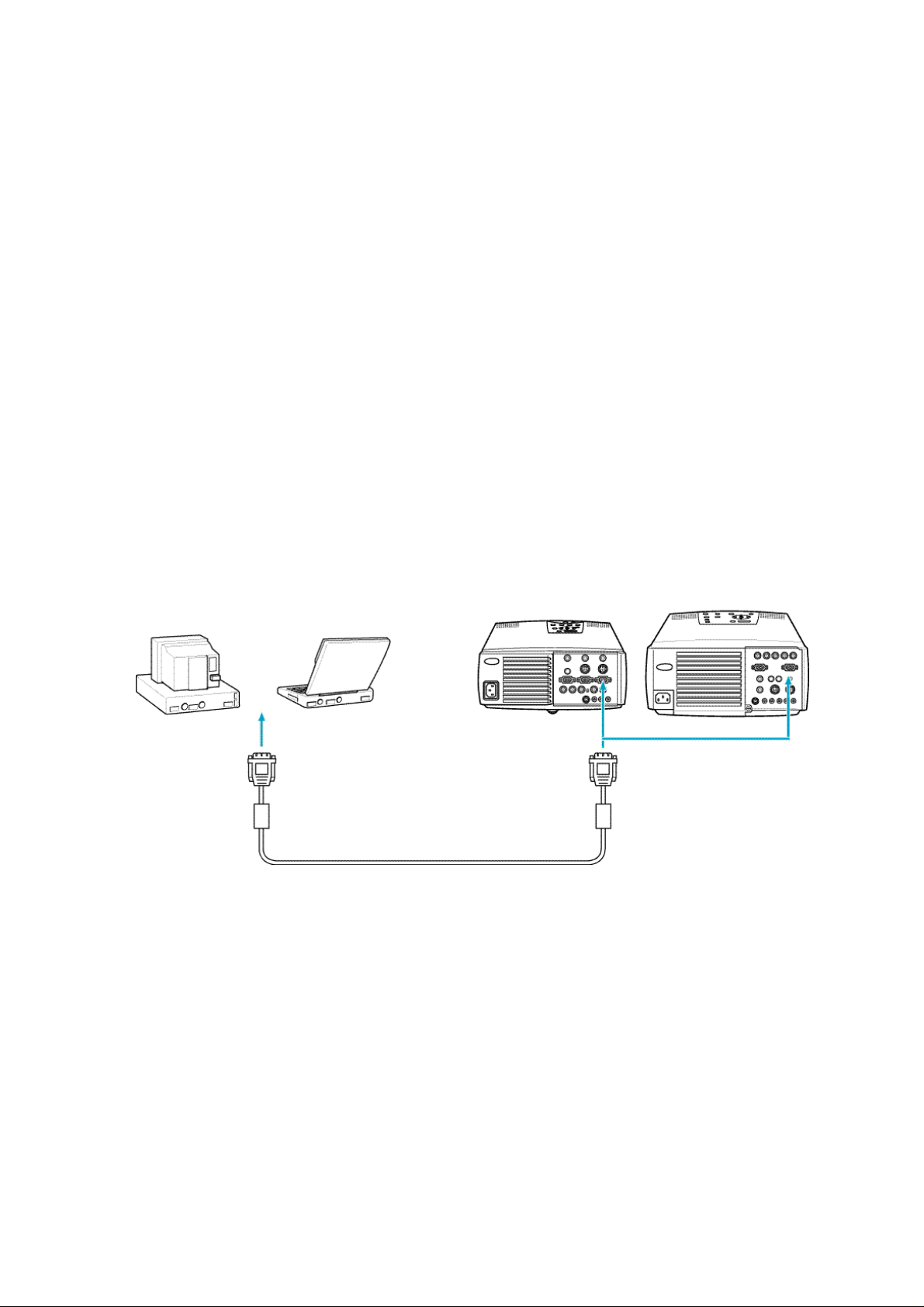
• Projecting the computer image
The computer cable supplied with the projector can be used to connect to a computer.
Note:
• If the projector is located at a distance from a computer, an optional 3 m computer cable
ELPKC09 can be used to connect to the computer.
• Except for a computer with the "15-pin micro-D-style" port, an adapter can be used to connect to
a computer.
• To connect a Macintosh desktop computer or PowerBook, the MAC monitor adapter supplied
with the projector can be used to connect to it.
Caution:
• If a universal extension cable is used to connect to a computer, always use a coaxial cable with a
coaxial wire for the H Sync and V Sync of the Video signal to avoid an unnecessarily long
cabling. The long cabling may cause image noise.
• Never tie the computer cable and power cable together. It may cause malfunction.
Monitor port (video port)
on computer
Computer cable
EMP-7350/7250/5350 EMP-8000
Computer 1 terminal
20
Page 21
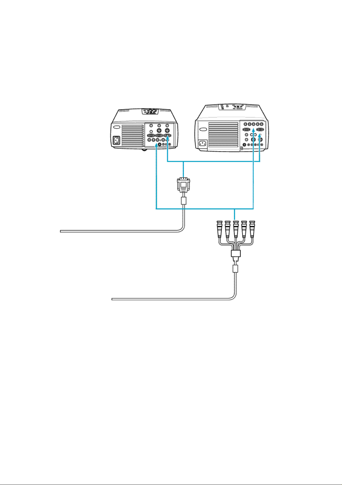
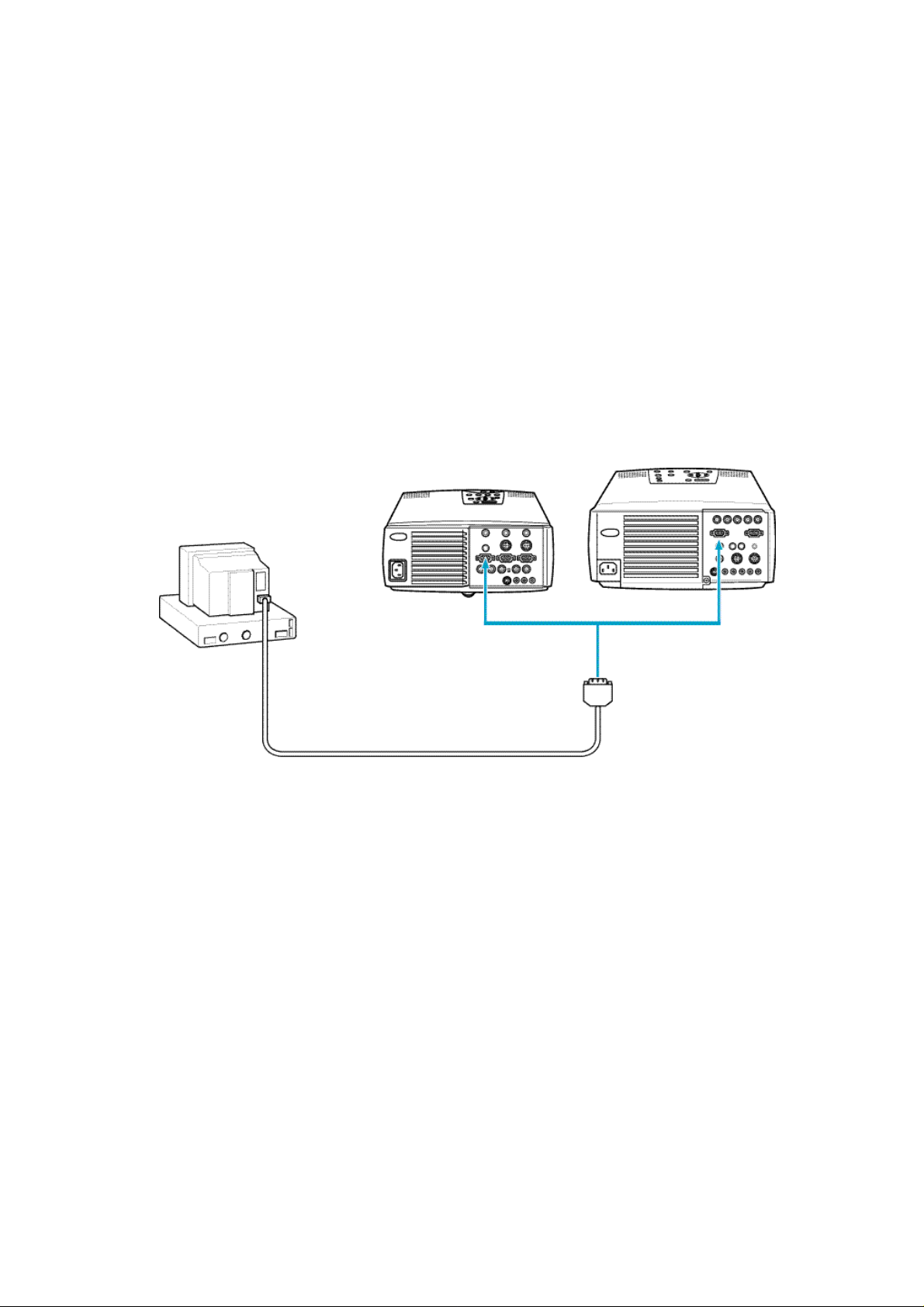
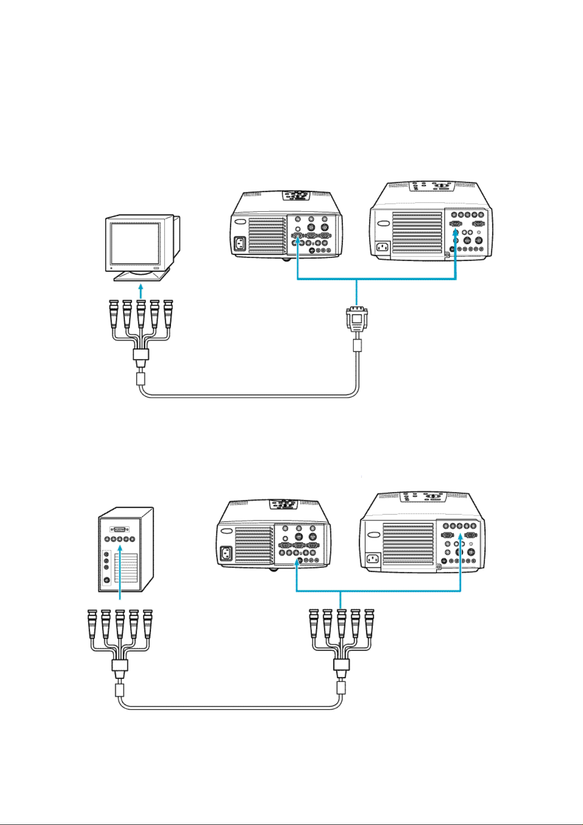
<Connecting two computers>
In addition to the computer cable supplied with the projector, an optional 1.8 m (ELPKC02) or 3 m
(ELPKC09) computer cable is required to connect to a computer.
Memo
Prepare a cable with the connector at the end of the computer mating to the output terminal of it.
EMP-7350-7250/5350 EMP-8000
Computer2/BNC
terminal
computer 1 terminal
Computer2/BNC
terminal
Monitor terminal of computer
Monitor terminal of computer
21
Page 22
<Projecting the projector image on a monitor display>
The following figure shows the cable connection to project the projector image on a monitor
display.
Note:
• Except for a computer with the "15-pin micro-D-style" port, an adapter can be used to connect to
a computer.
• To connect a Macintosh desktop computer or PowerBook, the MAC monitor adapter supplied
with the projector can be used to connect to it.
Caution:
• If the projector is located at a distance from a monitor, a universal extension cable is used to
connect to it. Avoid an unnecessarily long cabling. The long cabling may cause image noise.
• Never tie the monitor cable and power cable together. It may cause image noise.
EMP-7350/7250/5350 EMP-8000
Monitor cable
Computer Out
terminal
Monitor Out terminalCompute Out terminal
Monitor Out
terminal
22
Page 23
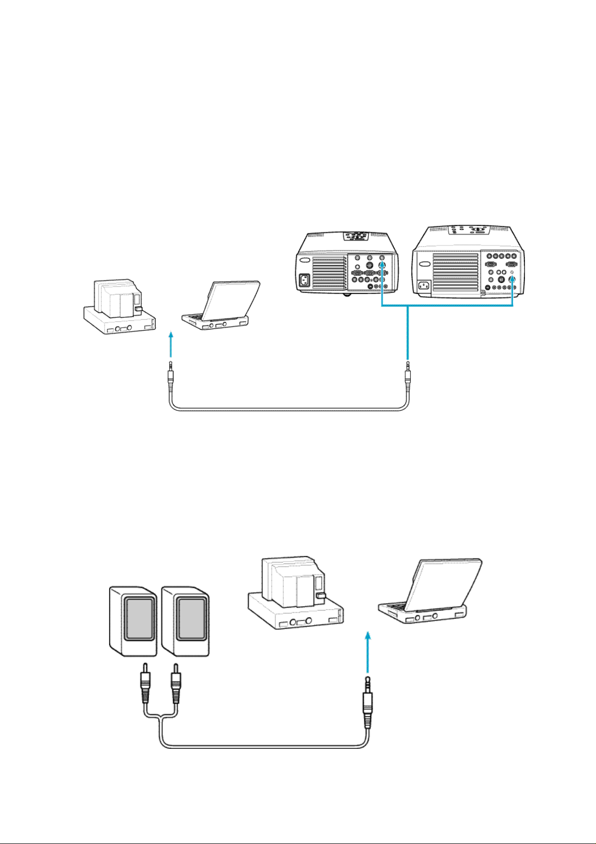
<Outputting the computer voice from the projector>
An 3W x 2 (output) amplifier is built into the projector.
Note:
• If the projector is located at a distance from a computer, a commercially available audio cable
(with a 3.5 mm stereo mini plug at the end of projector) can be used to connect to the computer.
Caution:
• If a commercially available universal extension cable is used to connect to a computer, install a
cabling as short as possible. The unnecessarily long cabling may cause image noise.
EMP-7350/7250/5350 EMP-8000
Audio 1 terminal
Audio output port on computer
Audio cable (supplied with this projector)
<Connecting a computer directly to external audio equipment>
The audio output port of the computer can be connected to external output equipment.
Note:
• To determine the necessary audio connecting cable, check the types of connection ports on the
computer and external audio equipment to be connected.
• Install a cabling as short as possible. The unnecessarily long cabling may cause image noise.
Computer
Audio cable
23
Page 24
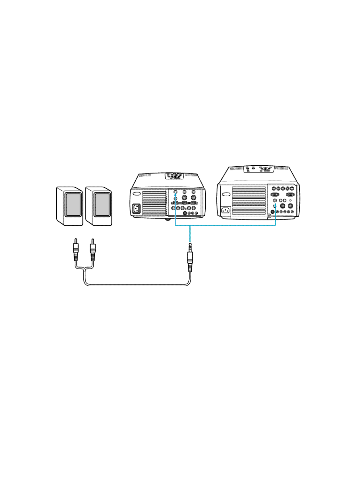
<Outputting the computer voice input to the projector from external audio
equipment>
A commercially available audio cable can be used to output the computer voice from external
audio equipment.
Note:
• When an audio cable is plugged in the Audio Output terminal on the projector, the computer
voice is automatically output to external audio equipment. In this case, no voice is output from
the speaker of the projector proper.
• To determine the necessary audio connecting cable, check the type of connection port of the
external audio equipment to be connected. A 3.5 mm stereo mini plug can be connected at the
end of the projector.
• Install a cabling as short as possible. The unnecessarily long cabling may cause image noise.
EMP-7350/7250/5350 EMP-8000
Audio cable
Audio Output terminal
24
Page 25
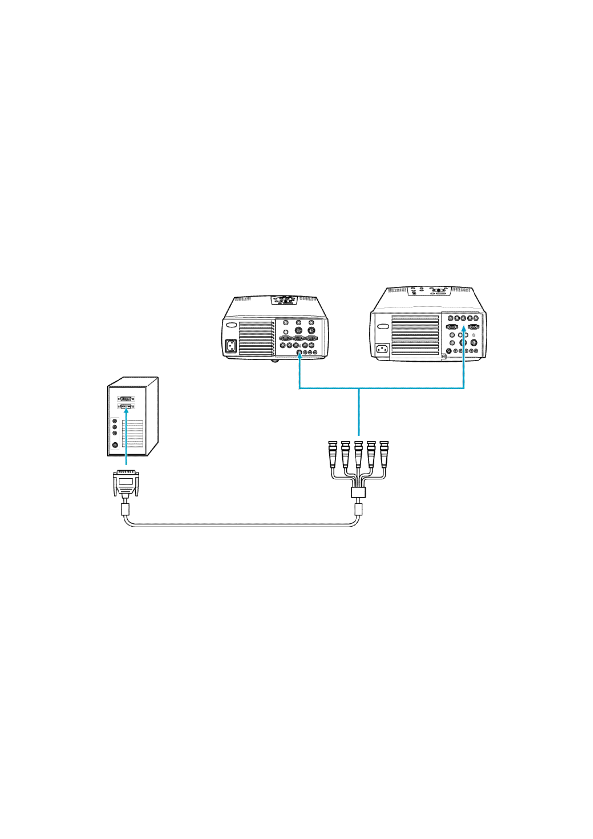
<Connecting to a workstation>
Note:
• If the projector is located at a distance from a workstation, a universal extension cable can be
used to connect to the workstation. Avoid an unnecessarily long cabling. The unnecessarily
long cabling may cause image noise.
• Never tie the EWS cable and power cable together. It may cause image noise.
• To project the computer image using the BNC terminal, make the necessary settings as referring
to the section "Setting the BNC terminal entry mode" described below.
If the workstation has a 13w3 port:
With the projector, an optional 3.0 m (ELPKC12) "13w3-5BNC" cable can be used to connect to a
workstation.
EMP-7350/7250/5350 EMP-8000
13w3 - 5BNC cable
Computer1 terminal
25
Page 26
<If the workstation is a 5BNC port (1):>
For EMP-7350/7250/5350, a commercially available "15-pin micro-D-style - 5BNC" cable can be
used to connect to a workstation.
For EMP-8000, the computer cable supplied with this projector (15-pin micro-D-style - 5BNC) can
be used to connect to a workstation.
EMP-7350/7250/5350 EMP-8000
Computer1 terminal
15-pin micro-D-style - 5BNC cable
<If the workstation is a 5BNC port (2):>
A commercially available "5BNC - 5BNC" cable can be used to connect to a workstation.
EMP-7350/7250/5350 EMP-8000
BNC terminal
5BNC - 5BNC cable
26
Page 27
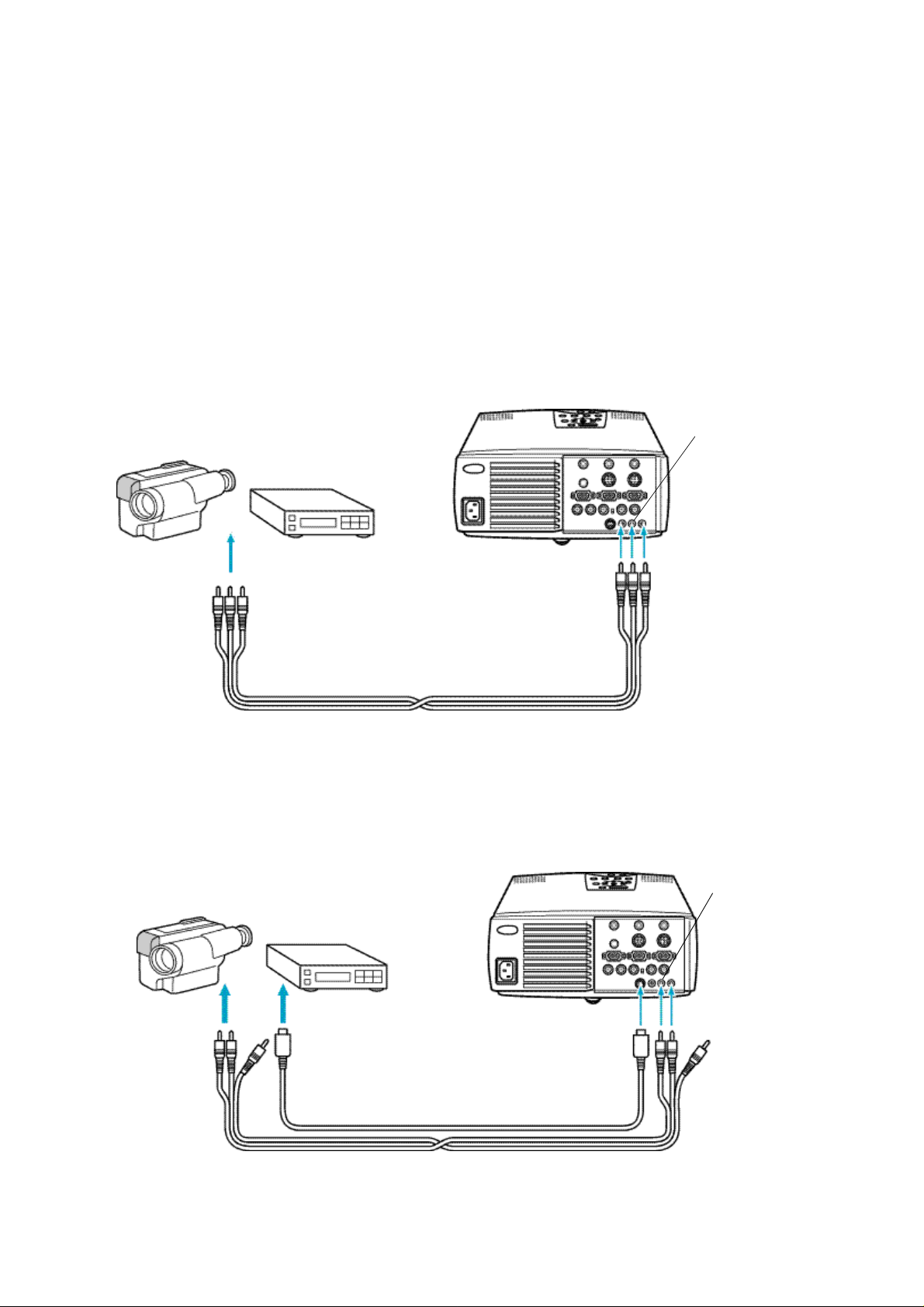
2-2-2.Connecting to a video source
<Model EMP-7350/EMP-7250/EMP-5350>
Note:
• If the projector is located at a distance from a video source, a universal extension cable can be
used to connect to a workstation. Avoid an unnecessarily long cabling. The unnecessarily long
cabling may cause image noise.
• Never tie the A/V cable and power cable together. It may cause image noise.
• Inputting the composite video signal
• Inputting the composite video signal
The A/V cable supplied with this projector can be used to connect to a video source.
Audio terminal L
(white)
Video terminal(yellow)
Audio terminal L (white)
Audio terminal R (red)
A/V cable (supplied with this projector)
Video terminal
(yellow)
Audio terminal R
(red)
• Inputting the S-Video signal
A commercially available S-Video cable can be used to connect to a video source as it is not
supplied with the projector.
Audio terminal L
(white)
Audio terminal R
(red)
Audio terminal
L (white)
Audio terminal
R (red)
S-Video terminal
S-Video terminal
Commercially available S-Video cable
A/V cable (supplied with this projector)
27
Page 28

• Inputting the component (color-difference) video signal
Audio terminal L
Note:
• Connect the projector to a video source as follows:
Video source Projector
R-Y R/R-Y
Y G-R (G Sync)
B-Y B/B-Y
• To project the computer image using the BNC terminal, make the necessary settings as referring
to the section "Setting the BNC terminal entry mode" described below.
R/R-Y terminal G-R(G Sync) terminal R/B-Y terminal
(white)
Audio terminal L
(white)
Audio terminal R
(red)
R-Y terminal
Y terminal
B-Y terminal
Commercially available Video
cable
A/V cable (supplied with this projector)
Audio terminal R
(red)
28
Page 29

<Model EMP-8000>
• Inputting the composite video signal
Audio terminal L
(white)
Video terminal(yellow)
Audio terminal L (white)
Audio terminal R (red)
A/V cable (supplied with this projector)
Video terminal
(yellow)
Audio terminal R
(red)
• Inputting the S-Video signal
A commercially available S-Video cable can be used to connect to a video source as it is not
supplied with the projector.
Audio terminal L
(white)
Audio terminal L
(white)
Audio terminal R
S-Video terminal
S-Video terminal
Commercially available S-Video cable
A/V cable (supplied with this projector)
29
Audio terminal R
(red)
Page 30

• Inputting the component (color-difference) video signal
Audio terminal L
Note:
• Connect the projector to a video source as follows:
Video source Projector
R-Y R/R-Y
Y G-R (G Sync)
B-Y B/B-Y
• To project the computer image using the BNC terminal, make the necessary settings as referring
to the section "Setting the BNC terminal entry mode" described below.
R/R-Y terminal G-Y(G Sync) terminal R/B-Y terminal
(white)
Audio terminal L
(white)
Audio terminal R
(red)
R-Y terminal
Y terminal
B-Y terminal
Commercially available Video
cable
A/V cable (supplied with this projector)
Audio terminal R
(red)
30
Page 31

• Setting the BNC terminal entry mode
To use the BNC terminal, set the input video signal mode as described below.
(1) Press [Menu] button to display the Main menu. Press [Sync +, -](control panel) or
[Enter](remote control) button on the Main menu to select Setting.
(2) Press[ (Enter) (control panel) or [Enter] (remote control).Press [Sync +, -](control
panel) or [Enter](remote control) button to select "BNC".
(3) Press [Tracking +, -] (control panel) or[Enter] (remote control) button to select
RGB.
RGB : When the computer signal is used.
YcrCb : When the video signal is used.
(4) Press Menu button to close the menu.
(5) Place the BNC switch of the I/O terminal at the back of the projector to the "BNC"
side.
(6) For EMP-7350/EMP-7250/EMP-5350, place the BNC switch of the I/O terminal at
the back of the projector to the "BNC" side.
31
Page 32

2-3.Mounting Position and Location
• This Ceiling Mount is used to mount Epson Multi-Media Projectors directly on the ceiling.
• The design of the actual product may not be identical to that shown in the illustration.
• Specifications are subject to change without notice.
Safety Cautions
The warning mark shown below is used throughout this instruction manual to ensure correct usage
and to prevent personal injury or property damage. Please read the instructions carefully and
understand the contents before proceeding.
2-3-1.Positioning the projector and screen
• Positioning the projector and screen
Mount the projector and screen as shown in the figure below.
Bottom Side view
The ideal position is with the projector
mounted perpendicular to the screen.
Unit:mm A B C D E F G H
EMP-7350
EMP-7250
EMP-5350
EMP-8000 12 12 185 118 294 181 213 69-79
* Dimensions are for reference only and need not be exact.
10 10 186 114 236 166 213 56
Mount the projector so that the operation
switches are on the bottom.
It can be
adjusted with
the lens shift
function.
32
Page 33

2-3-2.Assembly and Mounting
• Projector Mounting
(1) Turn the projector upside down, so that the side
with the control switches is facing down.
(2)Set the projector mounting bracket and tighten
using 4 projector lock screws.
Projector is to be mounted with the
lens facing the same direction as the
longer side of the mounting bracket.
Projecter lock screws
• Installing on the Ceiling
Fasten the mounting bracket fixture to the ceiling with nuts and bolts that fit the anchor bolt, etc.,
using the four elongated holes.
Mounting braket
mounting fixture
Adjustment
bracket
First, mount only the ceiling mounting bracket. Then the assembled adjustment bracket and
projector may be installed.
Ceiling contact surface dimensions
Unit: mm
Warning
• All screws have not been tightened completely at the time of purchase. Tighten all screws
completely before installing to ceiling. Failure to do so may result in the unit falling.
33
Page 34

2-3-3.Adjustment Function
Warning
• Support from the bottom while adjusting. After adjustment, completely retighten all of the screws.
Can result in dropping.
(1)Tilt adjustment (adjustable range:
approx. 5 degrees up/down)
If the projected image is at an angle
on the screen, loosen the tilt
adjustment screws then adjust the
projector by moving it vertically.
(2)Horizontal angle adjustment:
(adjustable range: approx. 5
degrees right/left)
If the image is shifted to the left or
right in relation to the screen,
loosen the mounting bracket
fixture screws and adjust by
rotating the projector to the left or
right.
Screen
g
a
m
I
e
Tilt adjustment lock screw
(3)Vertical angle adjustment:
(adjustable range: approx. 5
degrees up / 10 degrees down)
To move the projected image on
the screen vertically, loosen the
vertical angle adjustment screws
then adjust by turning the unit.
ate
Vertical angle
adjusiment screw
Rotate
34
Page 35

2-3-4.Example of mounting to ceiling
• For concrete ceilings
(1)Mount common anchor and bolts (available in stores) to the concrete ceiling.
Anchor
(Red head)
Mounting bracket
mounting fixture
Concrete
Nut
Bolt
(2)Mount the ceiling mounting bracket using common nuts (available in stores).
• In case there is another layer below the concrete or if mounting cannot be made directly, use
the separately sold pipe.
Warning
• When mounting to ceiling, set parts so that they can withstand the weight of the projector main
unit and ceiling mounting bracket, as well as rocking to prevent unit from dropping.
• Epson will not be liable for any accidents occurring from the unit dropping due to improper
mounting, etc.
35
Page 36

2-3-5.Ceiling Plate and Pipe Configurations
• Ceiling plate configuration
units : mm
• Pipe configurations
L dimension
• Pipe 370(ELPFE01) 370mm
• Pipe 570(ELPFE02) 570mm
• Pipe 770(ELPFE03) 770mm
Hole for fastening the ceiling
installation clamp catch.
L
• It is not possible to directly connect two pipes together.
Hole for fastening to ceiling
plate.
36
Page 37

• Securing the Ceiling Plate to the
Ceiling
Fasten to a structural member with 4
slots (elongated holes) and having
sufficient strength in the ceiling.
• Installing the Pipe
(1) First of all, set the ornamental
cap on the pipe as shown in
the drawing. At this point,
fasten with the ornamental cap
setscrew located below the
hole for inserting the pipe thruhole bolt.
(2) Next, set the pipe into the
ceiling plate and secure by
using the pipe thru-hole bolt
and pipe set-nut as shown.
(3) Change the ornamental cap
position according to the height
of the ceiling and fasten
securely with the setscrew.
Pipe set-nut
Pipe
Ornamental cap
Ceiling plate
Large hole
Pipe thru-hol
bolt
• Installing to the Ceiling
<When Attaching to ConcreteÅÑ
(1) Drill a hole so the pipe can
penetrate the ceiling.
(2) Fasten the anchors (available
in stores) to the concrete as
shown in the drawing.
(3) Fasten the ceiling plate body
with the installation bolts
(available in stores).
Ceiling p
Ceiling
Pipe
37
lat
Concrete
e
Ornamental cap
Anchors
Installation bolts
Page 38

<When Attaching to a Steel Fram>
(1)Drill a hole so the pipe can
penetrate the ceiling.
(2)Prepare an installation plate
that matches the steel frame
(see drawing) and secure it to
the steel frame as shown.
(3) Fasten the ceiling plate body to
the installation plate with the
installation bolts (available in
stores).
Ceiling
Set-bolts
IInstallation plate
Steel
frame
Installation bolt
Ornamental cap
Pipe
Ceiling Plate
WARNING
• When mounting in the ceiling, install each part so it can withstand the weight of the projector
body, ceiling suspension clamps, ceiling plate and pipe weight and also so it withstand side
sway. Failure to take this into account may cause the projector and hardware to drop to the floor.
• Our company can bear absolutely no responsibility for accidents, damage or injury due to
dropping or falling of equipment due to an installation of insufficient strength.
• This product is not of the rotating type and should never be rotated after the position has been
adjusted and the screws tightened.
Any attempt to rotate can cause the projector to fall. After installation, any change in the direction
or angle should be made by a specialist.
• Never loosen any of the bolts, screws or nuts after installation.
• People must never hang from the projector.
38
Page 39

2-3-6.Using the ceiling mounting bracket fixture and pipe
The projector can also be mounted using the optional ceiling plate and pipe as described
below.
• Installing the Flange
• Assemble the flange and mounting bracket using the dimensions shown in the diagram below.
• Install so that the optical axis of the projector lens is perpendicular to the screen.
• Refer to page 13 and projector for information concerning the distance from the screen.
Pipe A dimension
Pipe370 ELPFP01 600-750
Pipe570 ELPFP02 800-900
Pipe770 ELPFP03 1000-1150
Pipe is adjustable in increments of 50mm.
You can use one of the following 2 methods to set the pipe in the mounting bracket fixture:
1.Set the ceiling mounting bracket onto the pipe after first finishing all assembly of the ceiling
mounting bracket and projector, etc.
2.Mount only the ceiling mounting bracket onto the pipe, then assemble all the other
components including the projector.
Assemble as follows using either of the above 2 methods.
39
Page 40

Warning:
• Each part must carry a weight of each of the projector proper, ceiling mount, and ceiling plate
and pipe, and withstand lateral vibration adequately. Failure to do so may result in injury due to
falling.
• Neither SEIKO EPSON CORPORATION nor its affiliates shall be liable to the purchaser of this
product or third parties for damages, losses, costs, or expenses incurred by purchaser or third
parties as a result of falling.
• The projector is not rotatable. Never turn the projector after it is adjusted to the proper direction.
Rotating the projector can result in injury due to falling. Refer all works including correction to
the direction and angle of the projector to your dealer after installation.
• Never loosen bolts, screws, and nuts after the projector is mounted properly.
• Never allow anybody to hang from the projector.
ÅúFastening the Pipe, and Ceiling Mounting Bracket
(1)Set the ceiling mounting bracket onto the
pipe.
Pipe
Ceiling mounting
bracket
(2)Mount the ceiling mounting bracket catch
as shown below and secure with the
catch set-bolt and nut.
Catch set-nut
Ceiling mounting
bracket catch
Has angular
shape
Catch set-bolt
Insert through the
pipe
40
Page 41

(3)Lower the ceiling mount fixture onto the
ceiling mount fixture catch.
Position the projector so that the opticla
axis of the lens is perpendicular to the
screen and tighten the pipe screw.
Pipe lock screw
Toward the screen
41
Page 42

2-3-7.Adjustment Function
Warning
• Support from the bottom while adjusting. After adjustment, completely retighten all of the screws.
• Provide sufficient support when removing the pipe through bolt. Can result in dropping.
(1)Horizontal angle adjustment
If the image is shifted to the left or
right in relation to the screen,
loosen the pipe screw and adjust
by rotating to the left or right.
(2)Height adjustment
When making large changes in the
vertical position of the image on the
screen, remove the pipe through
bolt and pipe lock nut, and adjust
by sliding the pipe. Adjust using the
table and drawing shown at
right.Use the mounting bracket to
fine tune the vertical adjustment
and tilt.
Pipe lock screw
g
e
m
a
I
Pipe lock nut
42
Pipe through bolt
Page 43

• Using the ceiling-hung projector
When the projector is hung upside-down from the ceiling, the projected image is mirrored vertically
(top-bottom) and horizontally (left-right). Make the necessary settings according to the following
steps.
(1) Press [Menu] button to display the Main menu. Press [Sync +, -] (control panel) or
[Enter] (remote control) button on the Main menu to select "Advanced".
(2) Press [ (Enter) (control panel) or [Enter] (remote control).
(3) Press [Sync +, -] (control panel) or [Enter] (remote control) button to select
"Ceiling".
(4) Press [Tracking +, -] (control panel) or [Enter] (remote control) button to select
"ON".
(5) Press [Menu] button to close the menu.
43
Page 44

• Projecting the image from the behind of the screen using the ceiling-hung
projector
(1) Press [Menu] button to display the Main menu. Press [Sync +, -] (control panel) or
[Enter] (remote control) button on the Main menu to select "Advanced".
(2) Press [ (Enter)] (control panel) or [Enter] (remote control).
(3) Press [Sync +, -] (control panel) or [Enter] (remote control) button to select "Rear
Proj.".
(4) Press [Tracking +, -] (control panel) or [Enter] (remote control) button to select
"ON".
(5) Press [Menu] button to close the menu.
44
Page 45

2-3-8.Checking that the projector is operational
(1) Make the necessary connection to the power supply, computer, and video source.
(2) Remove the projector lens cap.
Caution:
If the projector is used with the lens cap installed, it may be melted due to heat.
(3) Place the RC ON OFF switch on the remote control to "ON".
Note:
If the RC ON OFF switch on the remote control is not placed to "ON", you cannot operate the
projector with the remote control.
(4) Press the Power button on the remote control to turn on the projector.
ELP-7350/7250/5350 ELP-8000 Remote control
(5) Input the computer or video signal to check that the image is projected properly.If
you cannot input the computer or video signal, press [Menu] button to check that
the menu displayed is projected properly.
Note:
If necessary, check the activation of the projector and functions such as Zoom in and Zoom out.
45
Page 46

3.Installing the stack multi-screen(Model EMP-8000 only)
The stack multi-screen can be used to project the image at about double brightness by installing
two projectors of the same model vertically and projecting the same image simultaneously.
It uses the stack fitting and the lens shift function provided with EMP-8000.
3-1.The following tips should be kept in mind when you install the
stack multi-screen:
• Projectors of the same model must be used.
• Lenses of the same type must be used.
• The same video sources must be used.
• Projectors must be mounted using the stack kit.
If they are mounted without the stack kit, the adjustment can not be made easily.
• It is recommended to project the computer image as a stack. However, if the video signal is
projected, refer to the section "Projecting the video image as a stack" for details.
46
Page 47

3-2.Connection for stack projection of the computer image
In case of the stack-connection, the first projector is connected as a master , and the next
projector is connected as a slave projector 1. Up to 4 projectors including the master projector can
be connected on the stack-connection.
3-2-1.If the computer has a 15-pin micro-D-style (BNC) output port
Prepare the necessary number of 15-pin micro-D-style cables for connecting the projectors to be
used.
(1)Connect the one end of the 15-pin micro-D-style (BNC) connector to the monitor
port of a computer.
Note:
• Except for a computer with the "15-pin micro-D-style" port, an adapter supplied with a computer
or a commercially available adapter can be used to connect to the computer.
• To connect a Macintosh desktop computer or PowerBook, the MAC disk top adapter and MAC
monitor adapter supplied with the projector may be required to connect to it.
• The following illustration shows the cabling using the "15-pin micro-D-style" cable. If the
computer has a BNC monitor port, install a cabling as referring to the instruction manual supplied
with the computer.
• The cable from the computer can be connected to the BNC on the master projector. In this case,
make the necessary settings as referring to the section "Setting the BNC terminal entry mode"
described below.
Caution:
• If a universal extension cable is used to connect to a computer, always use a coaxial cable with a
coaxial wire for the H Sync and V Sync of the Video signal to avoid an unnecessarily long
cabling. The long cabling may cause image noise.
• Never tie the computer cable and power cable together. It may cause malfunction.
(2)Connect the other one end of the 15-pin micro-D-style connector to the
"Computer1" of the master projector.
Master projector
Monitor port or
video port
Computer1
terminal
15-pin micro-D-style
47
Page 48

(3)Connect the "Monitor Out" of the master projector to the "Computer1" of the slave
projector 1 using the 15-pin micro-D-style cable.
Master projector
Monitor Out terminal
15-pin micro-D-style cable
Slave projector 1
Computer1 terminal
(4) If the slave projector 2 or 3 is used, repeat the step 3.
Example
Slave projector 2
Monitor port or
video port
15-pin micro-D-style cable
15-pin micro-D-style cable
Master projector
15-pin micro-D-style cable
Slave projector 1
Monitor Outterminal
Computer1 terminal
48
Page 49

3-2-2.Adjustment before stack projection
If two or more projectors are used to project images, it is required to make the necessary
adjustment including a superimposing of one image upon another and the color temperature.
<Adjusting the color with the test pattern>
The test pattern allows you to adjust the stack position color by projecting it on the screen.
To project the test pattern on the screen, a computer with the operating system (OS) of Window95/
98/NT4.0 or MAC OS 7.5 or later installed is required.
• For Windows users:
(1) Turn off the projector and computer.
(2) Turn on the projector, and then turn on the computer again.
Note:
• The message "Image signal is not input" is displayed until the video signal is output
from the computer side.
This message may not be displayed depending on the settings.
(3) Press [Computer] (control panel) or [Comp1] or [BNC] (remote control) button to
select the terminal connected to the computer of which image is projected.
The [Computer] button switches between [Computer1] and [Computer2] every
time it is pressed.
(4) Turn on the computer, and start Windows. Insert the floppy disk labeled "Test
Pattern Disk" supplied with the projector in the floppy disk drive.
Note:
The test pattern disk includes an application for displaying the color pattern, not for changing the
settings such as the display driver.
(5) Wait for about 15 minutes to stabilize the system for correct adjustment.
(6) Project the test pattern.
<1> Click Start button on the task bar. The popup menu appears. Click Run on
the popup menu.
<2> Type the drive name and "\TESTPAT.EXE" in half size of character. Click OK
button.
* The Run dialog box above appears for Windows98 users when the test pattern disk is inserted in
the Drive A.
49
Page 50

(7) The test pattern is projected after about 20 seconds.
Note:
• If you use a monitor with the resolution lower than 1,208 x 1,024 dots, the display of the test
pattern is slightly different.
• Move the mouse pointer to the low end of the screen. If the mouse pointer is not located at the
required position, the adjustment may not be made properly.
• Similarly, move an item such an icon and tool bar to the low end of the screen if it is displayed.
ÅúUsing the lens shift function
The lens shift function can be used to move the projected image up and down.
To use this function, adjust the side position of the projected image with the stack fitting.
Then, rotate the lens shift knob to superimpose one image on another.
Note:
• The menu can be used to adjust the projection position horizontally and vertically.It is noted that
the adjustment can be changed due to the image signals (changes in output mode and display
color, etc.) from the computer.
• The stack fitting can be used to adjust a superimposing of one image upon another horizontally.
Lens shift knob
50
Page 51

• Color setting
If two projectors are mounted with the stack, set the color temperature, and black and white levels
so that they provide the same color temperature.
(1) Press [Menu] button to display the Main menu. Press [Sync +, -] (control panel) or
[Enter] (remote control) button on the Main menu to select "Advanced".
(2) Press [ (Enter)] (control panel) or [Enter] (remote control). Press [Menu] button.
Press [Sync +, -] (control panel) or [Enter] (remote control) button to select "Color
Temp.".
(3) Press [Tracking +, -] (control panel) or [Enter] (remote control) button to select
"Manual".
• If "Auto" is selected, the color adjustment is made automatically.Proceed to the
step 6
(4) Press [ (Enter)] (control panel) or [Enter] (remote control).
(5) Press [Tracking +, -] (control panel) or [Enter] (remote control) button to set the
color.
(6) Press [Menu] button to close the menu.
51
Page 52

3-3.Operating/controlling the stack-connected projectors
To establish or release the stack-connection, use the "application software ELP-Link IV" which is
installed in a computer.
For further information about the installation of ELP-Link IV, refer to the Owner’s manual supplied
with the projector.
3-3-1.Establishing the stack-connection
(1) Connect the master projector to a computer.
Caution:
Extending the main cable for connection may cause malfunction. If extending a cabling, a serial
cable must be extended.
• For IBM PC/AT compatible machine (DOS/V PC), NEC PC-98 or compatible machine users
* For NEC PC-98 or compatible machine users, an adapter supplied with a computer or a
commercially available adapter is required to connect to it.
Master projector[
To serial port
PC serial cable
• For Macintosh users:
To printer or
modem port
MAC serial cable
To Mouse/Com1 or 2
Main cable
Master projector[
To Mouse/Com1 or 2
Main cable
(2) Plug all stack-connected projectors in the wall outlet, place them in the standby
mode. (The orange power indicator comes on.)
52
Page 53

(3) Turn on the computer connected to the master projector, and start "ELP-Link IV".
(4) When "ELP-Link IV" is started, the following window is displayed. Always select
"No" on the window.
(5) Select the menu item as follows.
For Windows users: Select "About ELP-Link IV" on the pull-down menu appeared
by clicking Help.
For Macintosh users: Select "About ELP-Link IV" on the pull-down menu appeared
by clicking the apple mark "?".
The version information window appears.
(6) Assign a password as follows.
For Windows users: Press [Ctrl] + [I] key.
For Macintosh users: Press [Command] + [I] key.
The version information window disappears, and the window to enter a password
appears.
(7) To assign a password, type the password, and click OK button.
(A password must be up to 16 alphanumeric characters.)
If you do not want to assign a password, just click OK button without any entry.
*No password is entered at installation.
(8)The Installer specific setting window appears.
53
Page 54

[1]
[2]
[3]
[4]
[8]
[9]
[7]
[5]
[6]
[11][10]
54
Page 55

The following table shows the buttons/boxes on the Installer specific setting window and the
respective description/function.
Button/box Description/function
[1]Projector select button Select a projector to be set. It works in the same manner as with the
projector control window. It disables all buttons on projector 1 to 4
on a standalone connection.
[2]Function select
combobox (pop-up
menu)
[3]Setting item
combobox (pop-up
menu)
[4]Subsetting item
combobox (pop-up
menu)
[5]Setting entry area Consists of the edit box and combobox (pop-up menu). For an
[6]Send button Sends the setting displayed to the projector after this button is
[7]Lock/unlock button Disables all setting items and controls in the group box if clicking the
[8]Stack setup button Establishes the stack-connection by clicking this button.
[9]Stack release button Releases the stack-connection by clicking this button.
[10]Password change
button
[11]Stop setting button Terminates the Installer specific settings. It returns to the normal
Selects a function. Generally, it adapts to the OSD on the projector.
The items displayed include Image (computer), Image (video),
Audio, Effects, Setting, User logo, and Advanced.
Changes the function of this control with this box. Generally, it
adapts to the OSD on the projector.
This box can be used if there is a menu entry below the setting item.
If not, disable this box. It prevents the effects function setting from
being changed (only lock/unlock can be possible).
numerical setting item, the edit box is enabled. For a selection item,
the combobox (pop-up menu) is enabled.
pressed if any value is entered (or selected) in the Setting entry
area. It is disabled if not.
Large key button. It enables them by clicking it again. This button
disables the Subsetting item combobox currently displayed (pop-up
menu), Setting entry area, and Send button if clicking the Small
key button. It enables them by clicking it again. It disables the
Initialize all tabs button on the projector control if all initialization is
locked. It enables or disables the projector control items of the ELPLINK IV itself according to the current status.
Changes the password to move to the Installer specific setting
window. The password change window appears by clicking this
button .
projector control window, and enables each item on the function
select combobox (pop-up menu) by clicking this button.
(9) Click Stack setup button.
When the stack-connection is established, the window indicating that the stackconnection is made successfully appears.
(10) Click OK button.
55
Page 56

3-3-2.Operating the stack-connected projectors
When the stack-connection is established successfully, you can operate them using the control
panels on the projectors, remote control and ELP-Link IV.
• Turn on all projectors at a time
Pressing the Power button on the remote control, or sending the power-on command through
ELP-Link IV turns on all stack-connected projectors.
• Turn off all projectors at a time
Pressing the Power button on the remote control, or sending the power-off command through
ELP-Link IV turns off all stack-connected projectors.
• Releasing the stack-connected projectors
Click the ? Stack release button on the ELP-Link IV Installer specific setting window releases all
stack-connected projectors, returns them to the standalone connection.
When the projectors are successfully released, the window indicating the stack-connection is
released appears.
This function can release the projectors only with the lamp off.
• Changing the password
To change the password, enter the old password, new password, and new one for confirmation
correctly without any fail.
If any of them is entered incorrectly, the alert message appears, and all edit entries are cleared.
A password must be up to 16 alphanumeric characters. If you enter a password using 17 or
more characters, it sounds a beep as an error warning.
The password entered is displayed in the form of "*" in Windows, and "." in Macintosh.
3-3-3.Alert message on the Installer specific setting window
The following alert messages are shown on the Installer specific setting window.
For alert messages other than those below, refer to the projector specific or common alert
messages.
Alert condition Alert message Button
If the stack setup button is pressed, and the
stack-connection is established.
If the stack release button is pressed, and
the stack-connection is released.
If the password is changed successfully. Password is changed. OK
If the password is entered incorrectly, or if
no password is entered.
Stack-connection is established. OK
Stack-connection is released. OK
Password is incorrect. OK
56
Page 57

3-3-4.Using the setting menu
• For Windows users:
A pull-down menu appears by clicking Menu on the Installer specific setting window.
Menu title Menu item Status Description
File (F) Open (O) Ctrl + O Enabled Opens up the file select dialog*1.
It can open a projector control file (with
a filename extension elp).
Opening a file sends the setting
(tracking base, lamp on time, PC
frequency) to projectors. Sync polarity,
preset, and input resolution are
excluded. Lock/unlock setting is also
sent. While opening a file and
changing projector settings, the dialog
"Please wait ..." appears.
Save (S) Ctrl + S Enabled Saves the current projector settings. It
saves the setting of the projector.
Save as (A).... Enabled Opens up the file select dialog to save
the projector settings with a different
name.
A file with a filename extension elp can
be used to save the setting of the
projector.
*1 At default (at the first start-up) the ELP-Link IV install folder is displayed. At the 2nd onward the
folder previously selected is displayed.
57
Page 58

• For Macintosh users:
A pull-down menu appears by clicking Menu on the Installer specific setting window.
Menu title Menu item Status Description
About ELP-Link IV Enabled Indicates version information.
File New Command + N Disabled
Open Command + O Enabled Opens up the file select dialog*1.
It can open a projector control file
(with a filename extension elp).
Opening a file sends the setting
(tracking base, lamp on time, PC
frequency) to projectors. Sync
polarity, preset, and input resolution
are excluded. Lock/unlock setting is
also sent. While opening a file and
changing projector settings, the
dialog "Please wait ..." appears.
Close Command + W Disabled
Save Command + S Enabled Saves the current projector settings.
It saves the setting of the projector.
Save as Enabled Opens up the file select dialog to
save the projector settings with a
different name.
A projector control file can be used to
save the setting of the projector.
Exit Command + Q Disabled
Edit Cancel Command + Z Disabled
Cut Command + X Disabled
Copy Command + C Disabled
Paste Command + V Disabled
Select All Command + ADisabled
Option Support presentation
Command + G
Open setting window Disabled
Always start under no
connection
Select port for
reconnection
Set test pattern... Disabled
Projector Send user logo Disabled
Send cursor/stamp Disabled
Help (OS8 or
later)
ELP-Link IV Help Disabled
Disabled
Disabled
Disabled
58
Page 59

Menu title Menu item Status Description
ELP-Link IV Help
(Sysytem7.*)
*1 Adjust the folder to the setting on the control panel.
59
Page 60

3-3-5.Operations and restrictions on the stack-connection
Some operations available on the stack-connection are different from those on the standalone
connection, and some restrictions are imposed on them.
• Operations
Operation Description
Resize This operation is performed from the master projector. Then, the slave
projectors are displayed against a dark background.
However, if using the control panel on the slave projector, it operates
individually in the same manner as with the standalone connection.
Menu[ Displays or hide the menu using the Menu button on the remote
control. If three projectors are stack-connected, they are activated or
deactivated in the following order every time the Menu button is
pressed; the master projector activated - slave projector 1 activated -
slave projector 2 activated - master projector deactivated .......
However, if using the control panel on the slave projector, it operates
individually in the same manner as with the standalone connection.
P In P Project the computer image as a parent, and the Video image as a
child on the screen. However, the slave projectors are displayed
against a dark background.
Mute This operation is performed from the master projector. Then, the slave
projectors are displayed against a dark background.
However, if using the control panel on the slave projector, it operates
individually in the same manner as with the standalone connection.
E-Zoom This operation is performed from the master projector. Then, the slave
projectors are displayed against a dark background.
60
Page 61

4.Installing the remote control receiver 4-1.Installing
The remote control receiver is required if you want to operate the projector at a distance of
10 m or more from it, or if the remote control cannot be pointed towards the remote control
sensor on the projector due to impediments.
Caution:
• The distance between the remote control receiver and the remote control must be kept within 8
m.
• Do not extend the remote control receiver cord with an extension cord. Extension may cause
malfunction.
• Do not place the remote control receiver in an area exposed to direct sunlight or a fluorescent
light.
(1) Turn off the projector and computer.
(2) Plug the remote control receiver cord in the "Remote" at the back of the projector.
Remote
terminal
Remote
terminal
EMP-7350/7250/5350 EMP-8000
(3) Place the remote control receiver at a place where it can be operated by the
remote control.
61
Page 62

5.Maintenance
Warning:
• Never open the cabinet of the projector except for your dealer or qualified service personnel.
Dangerous electrical voltages inside the projector can cause electric shock.
• Extra special care must be taken on handling the power plug/power connector. Always take the
following precautions when handling the power plug and power connector. Failure to do so may
result in fire or electric shock.
• Ensure that the power plug/power connector is free of dust before inserting it into a socket.
• Ensure that the power plug/power connector is inserted into the socket securely.
• Do not insert or disconnect the power plug/power connector with wet hands.
Caution:
• Never remove the lamp immediately after turning off the projector.
• Failure to do so may result in burns or injury.
• Let the projector cool for about 60 minutes after turning off it. Ensure that the projector is
sufficiently cooled down before replacing the lamp.
• Unplug the projector from the wall outlet before cleaning.
• Failure to do so may result in electric shock.
62
Page 63

5-1.Replacing the lamp
Caution
• Insert the lamp and fasten the lamp cover securely to turn on the projector without fail. For
safety, the projector turn itself off if the lamp cover is open.
Note:
• The total lamp usage time is automatically reset to 0 when the lamp is replaced with the new
one.
• Replace the air filter with the new one supplied with lamp after replacing the lamp as well.
5-1-1.Model EMP-7350/EMP-7250/EMP-5350
Replace the lamp as described below.
Use only replacement lamp part number ELPLP05 (optional).
(1)Turn off the projector. Unplug the power cable from the wall outlet after the
projector is cooled down sufficiently.
• The time required to cool down the projector varies with an ambient temperature.
(2)Lift off the lamp cover after the projector is
cooled down sufficiently.
• It takes about 60 minutes to cool down the
projector sufficiently.
• Use a screwdriver, coin, or similar object to
loosen the two retaining screws on the lamp
cover.
(3)Pull out the lamp.
• Use a screwdriver, coin, or similar object to
loosen the two screws holding the lamp in
position. Lift up the handle.
63
Page 64

(4)Gently insert the new lamp by lowering it
into position.
• Align the lamp, and push it as far as it
will go. Use a screwdriver, coin, or
similar object to tighten the screws you
loosened in step 3.
(5)Replace the lamp cover.
• Align the lamp cover, and push it. Use
a screwdriver, coin, or similar object to
tighten the screws you loosened in
step 2.
64
Page 65

5-1-2.Model EMP-8000
Replace the lamp as described below.
Use only replacement lamp part number ELPLP08 (optional).
(1)Turn off the projector. Unplug the power cable from the wall outlet after the
projector is cooled down sufficiently.
• The time required to cool down the projector varies with an ambient
temperature.
(2)Remove the fan after the projector is cooled
down sufficiently.
• It takes about 60 minutes to cool down
the projector sufficiently.
• Use a screwdriver supplied with the
optional lamp to loosen the two retaining
screws on the fan.
(3)Pull out the lamp.
• Use a screwdriver supplied with the
optional lamp to loosen the three screws
holding the lamp in position. Lift up the
handle.
(4)Gently insert the new lamp by lowering it
into position.
• Align the lamp, and push it as far as it will
go. Use a screwdriver supplied with the
optional lamp to tighten the screws you
loosened in step 3.
65
Page 66

(5)Replace the fan.
• Align the lamp cover, and push it. Use a
screwdriver supplied with the optional
lamp to tighten the screws you loosened
in step 2.
66
Page 67

5-2.Replacing the air filter
Replace the air filter with the new one supplied with lamp after replacing the lamp as well.
Caution:
Stand the projector with the handle at the top to prevent dust from entering the projector.
5-2-1.Model EMP-7350/EMP-7250/EMP-5350
(1)Turn off the projector. Unplug the power cable from the wall outlet after the
projector is cooled down sufficiently.
• The time required to cool down the projector varies with an ambient temperature.
(2)Lift off the air filter cover.
(3)Take out the air filter.
(4)Insert the new air filter.
(5)Replace the air filter cover.
67
Page 68

5-2-2.Model EMP-8000
(1)Turn off the projector. Unplug the power cable from the wall outlet after the
projector is cooled down sufficiently.
• The time required to cool down the projector varies with an ambient
temperature.
(2)Lift off the air filter cover.
* Stand the projector with the handle at
the top to prevent dust from entering
the projector.
(3)Insert the new air filter.
* Replace the filter cover by engaging the
retaining lug first, and then pressing the
hook.
68
Page 69

6.Product specifications
6-1.Projector specifications 6-1-1.Model EMP-7350/EMP-7250/EMP-5350
Product name Multimedia projector
Model name EMP-7350/ EMP-7250/ EMP-5350
Dimension 300 [W] x 129 [H] x 400 [D] mm (lens foot included)
Size of panel 1.3 inches (27 mm [W] x 20 mm [H] x 34 mm [from the upper left
corner to
the lower right corner])
Type of display Poly-silicon TFT
Drive <EMP-7350/EMP-7250>
Full line 12-phase block sequential writing
< EMP-5350>
Full line 6-phase block sequential writing
Resolution <EMP-7350/EMP-7250>
2,359,296 pixels (1024 (horizontal) x 768 (vertical) dots x 3)
<EMP-5350>
1,440,000 pixels (800 (horizontal) x 600 (vertical) dots x 3)
Focus adjustment Manual
Zoom adjustment Manual 1:approx. 1.3
E-Zoom with remote control 1:approx. 4
(Light source) Lamp UHE lamp Model ELPLP05, 150W rating
Maximum audio output 3W x 2 stereo
Internal speaker 2
Power supply 120 VAC, 50/60 Hz
Power consumption approx. 200 W
Operation temperature +5 to +40°C(non-condensing)
Storage temperature -10 to +60°C(non-condensing)
Weight approx. 6.2 kg
Connecting terminals
Computer 2 lines High-density 15-pin micro-D-style
(female)
Computer Output 1 line High-density 15-pin micro-D-style
(female)
Audio1 (for Computer1) 2 lines Stereo mini jack
Audio2 (for Computer2) 2 lines Stereo mini jack
Mouse/Com 2 lines 13-pin DIN jack
Video 1 line RCA pin jack
S-Video 1 line 4-pin micro-DIN-style
Audio input 2 lines RCA pin jack x 2 (L, R)
Remote 1 line Stereo mini jack
BNC 1 line 5BNC (female)
Audio output 1 line Stereo mini jack
69
Page 70

6-1-2.Model EMP-8000
Product name Multimedia projector
Model name EMP-8000
Dimension 305 [W] x 157 [H] x 475 [D] mm (lens foot included)
Size of panel 1.3 inches (27 mm [W] x 20 mm [H] x 34 mm [from the upper left
corner to
the lower right corner])
Type of display Poly-silicon TFT
Drive Full line 12-phase block sequential writing
Resolution 2,359,296 pixels (1024 (horizontal) x 768 (vertical) dots x 3)
Focus adjustment Manual
Zoom adjustment Manual 1:approx. 1.3
E-Zoom with remote control 1:approx. 4
(Light source) Lamp UHE lamp Model ELPLP08, 220W rating
Maximum audio output 3W x 2 stereo
Internal speaker 2
Power supply 120 VAC, 50/60 Hz
Power consumption approx. 360 W
Operation temperature +5 to +40°C(non-condensing)
Storage temperature -10 to +60°C (non-condensing)
Weight approx. 8.3 kg
Connecting terminals
Computer 1 line High-density 15-pin micro-D-style
(female)
Monitor 1 line High-density 15-pin micro-D-style
(female)
Audio1 (for Computer1) 1 line Stereo mini jack
Audio2 (for Computer2) 2 lines RCA pin jack x 2 (L, R)
Mouse/Com 2 lines Multipolar jack
Video 1 line RCA pin jack
S-Video 1 line 4-pin micro-DIN-style
Audio input 2 lines RCA pin jack x 2 (L, R)
Remote 1 line Stereo mini jack
BNC 1 line 5BNC (female)
Audio output 1 line Stereo mini jack
70
Page 71

6-2.Lens specifications
6-2-1.Long zoom lens (ELPLL02)
Focal length 68.3 to 116.2 mm
Zoom ratio 1:1.7
F number 2.14 to 2.98
Projection size 40 to 300 inches
Weight approx. 1900 g
6-2-2.Wide conversion lens (ELPCW01)
The projection distance when this lens is used is 0.765 times shorter than when the standard
lens is used if the screen size is same.
Magnification 1:0.765
Size 100 (diameter) x 90 mm (length)
Weight approx. 900 g
71
Page 72

6-3.Using the control panel on the projector
6-3-1.Model EMP-7350/EMP-7250/EMP-5350
[2]
[1]
[10]
[11]
[12]
[8]
[8]
[14]
[1]Operation indicator
It tells you the projector’s operating status.
[2]Power button
It is used to start or stop projection.
[3]Help button
It is used to describe how to handle a problem by item.
[3]
[4]
[5]
[6]
[7]
[8]
[7]
[9]
[4]Resize button
It switches the display dot mode and resize mode.
[5]Video button
It is used to switch to S-Video 1, Composite Video, or Component Video.
[6]>Esc button
It is used to terminate the function that is executed currently.
During menu or help operations, it is used to go back to the next higher layer.
[7]Sync button
It is used to adjust an overall image that is fuzzy or streaked.
During menu or help operations, it acts as a up or down arrow key.
[8]Tracking button
It is used to adjust an image with vertical fuzzy lines.
During menu or help operations, it acts as a right or left arrow key.
[9]Keystone (Volume) button
It is used to adjust an image with trapezoidal distortion. It can be used to adjust the volume with
this key and Shift button pressed simultaneously.
72
Page 73

[10]A/V Mute buttonì
It is used to switch to S-Video 1, Composite Video, or Component Video.
[11]Computer buttonì
It is used to switch to Computer 1, Computer 2, BNC (RGB), or Component Video.
[12]Menu button
It is used to display or hide the menu.
[13] (Enter) button
It is used to register a menu selection.
During menu or help operations, it is used to go forward to the next lower layer if any. If
menu or help operations are not performed, the computer image is optimized.
The input resolution is switched to "Auto" if it is set to "Manual".
[14]Shift button
It can be used to adjust the volume with this key and Keystone (Volume) button pressed
simultaneously.
73
Page 74

6-3-2.Model EMP-8000
[8]
[9]
[10]
[1]
[2]
[11]
[3]
[4]
[5]
[6]
[7]
[1]Operation indicator
It tells you the projector’s operating status.
[2]Power button
It is used to start or stop projection.
[3]Computer button
It is used to switch to Computer 1, Computer 2, BNC (RGB), or Component Video.
[12]
[13]
[14]
[4]A/V Mute button
It is used to cut off video and audio temporarily. You can project the user log during this
time. The video and audio are restored when pressing this button again, or adjusting the
volume.
[5]Resize button
It switches the display dot mode and resize mode.
[6]Video button
It is used to switch to S-Video, or Video.
[7]Shift buttonì
It can be used to adjust the volume with this key and Keystone (Volume) button pressed
simultaneously.
[8]Help button
It is used to describe how to handle a problem by item.
[9]Menu button
It is used to display or hide the menu.
74
Page 75

[10]Sync button
It is used to adjust an overall image that is fuzzy or streaked.
During menu or help operations, it acts as a up or down arrow key.
[11]Esc button
It is used to terminate the function that is executed currently.
During menu or help operations, it is used to go back to the next higher layer.
[12]Tracking button
It is used to adjust an image with vertical fuzzy lines.
During menu or help operations, it acts as a right or left arrow key.
[13] (Enter) button
It is used to register a menu selection.
During menu or help operations, it is used to go forward to the next lower layer if any. If
menu or help operations are not performed, the computer image is optimized.
The input resolution is switched to "Auto" if it is set to "Manual".
[14]Keystone (Volume) button
It is used to adjust an image with trapezoidal distortion. It can be used to adjust the volume
with this key and Shift button pressed simultaneously.
75
Page 76

6-4.Using the remote control
[1]Indicator
[1]
[2]
The remote control can be used commonly among all models.
6-4-1.Front
It comes on while the remote control signal is output.
[2]Remote control sender
It outputs the remote control signal.
[8]
[9]
[10]
[11]
[3]
[4]
[5]
[6]
[7]
[3]Power button
It is used to start or stop the projector.
[4]R/C ON OFF button
It is used to turn on or off the remote control.
If this button is not set to "ON", you can not operate
the remote control.
[5]Effects buttons
It is used to perform the special effect function
assigned to each button.
[6]Enter button
• It is used to register a menu selection.
• It is used to go forward to the next lower layer if
any.
• If the computer image is projected, it act as a left
mouse click.
• It is used to use the remote as a mouse pointer.
• During menu operations, it is used to navigate the
menus for selection of adjustment item.
[7]Esc button
It is used to terminate the function that is executed
currently.
During menu or help operations, it is used to go back
to the next higher layer.
If the computer image is projected, it act as a right
mouse click.
[8]Freeze button
It is used to keep the current or video image on the
screen temporarily. The image is unfreezed when
pressing this button again.
[9]A/V Mute button
It is used to cut off video and audio temporarily. You
can project the user log during this time. The video
and audio are restored when pressing this button
again, or pressing Volume button.
[10]E-Zoom button
It is used to perform the E-Zoom function.
[11] (Illumination) button
All buttons on the remote control are illuminated for
about 10 seconds.
76
Page 77

6-4-2.Inside of the cover
[1]
[2]
[3]
[4]
[5]
[6]
[7]
[8]
[9]
[10]
[11]
[1]Menu button
It is used to display or hide the menu.
[2]Comp1 button
CIt is used to switch to Computer1.
[3]S-Video button
It is used to switch to S-Video.
[4]Auto button
The computer image is optimized.
[5]Pin P button
It is used to display the video image as a child
image on the computer image.
[6]Volume button
It is used to adjust the volume.
[7]Help button
It is used to describe how to handle a problem by
item.
[8]Comp2/BNC button
It is used to switch to BNC.
To activate this button, place the BNC switch of the
I/O terminal at the back of the projector to the
"BNC" side(EMP-7350/EMP7250/EMP-5350).
[9]Video button
It is used to switch to Video.
[10]Resize button
If the computer image is projected, it switches the
display dot mode and resize mode. If the video
image is projected, switch the aspect ratio between
4:3 and 16:9.
[11]Preset button
It is used to promptly adjust the display by invoking
the preset value of the computer input
signal.
77
Page 78

6-5.I/O terminals
6-5-1.Model EMP-7350/EMP-7250/EMP-5350
[8]
[9]
[1]
[2]
[3]
[4]
[5]
[1]Audio Out
It is used to output the audio signal from the projector.
[6]
[10]
[9]
[10]
[8]
BNC Switch
[7]
[2]Remote
It is used to connect the optional remote control receiver.
[3]Computer Out
It is used to output the signal from the computer.
[4]BNC
•R/R-Y
•G/Y
•G Sync
•B/B-Y
•HD/Sync
•VD
It is used to input the BNC video signal from the workstation, or the component video signal
(color-difference signal) from the video.
To use the image from this terminal, place the BNC switch of the I/O terminal at the back of the
projector to the "BNC" side.
[5]S-Video
It is used to input the S-Video signal from the A/V equipment.
[6]Video
It is used to input the video signal from the A/V equipment.
78
Page 79

[7]L-Audio-R
It is used to input the audio signal from the A/V equipment.
[8]Computer1/2
It is used to input the video signal from the computer.
[9]GAudio1 /2
It is used to input the audio signal from the A/V equipment through a stereo mini jack.
[10]Mouse/Com1/2
It is used to connect to the computer when using the remote control as a wireless mouse, or
the Projector Software supplied with the projector.
79
Page 80

6-5-2.Model EMP-8000
[8]
[1]
[2]
[3]
[4]
[5]
[6]
[1]Monitor Out
It is used to output the video signal.
The signal input from the Computer and BNC terminals is output.
[2]Audio Out
It is used to output the audio signal from the projector.
[9]
[10]
[11]
[12]
[7]
[3]Remote
It is used to connect the optional remote control receiver.
[4]S-Video
It is used to input the S-Video signal from the A/V equipment.
[5]L-Audio-R
It is used to input the audio signal from the A/V equipment.
[6]Video
It is used to input the video signal from the A/V equipment.
[7]L-Audio-R
It is used to input the audio signal from the A/V equipment through a RCA pin jack.
[8]BNC
• R/R-Y
• G/Y
• G Sync
• B/B-Y
80
Page 81

• HD/Sync
• VD
It is used to input the BNC video signal from the workstation, or the component video signal
(color-difference signal) from the video.
To use the image from this terminal, place the BNC switch of the I/O terminal at the back of the
projector to the "BNC" side.
[9]Computer1
It is used to input the video signal from the computer.
[10]L-Audio2-R
It is used to input the audio signal from the A/V equipment through a RCA pin jack.
[11]Audio1
It is used to input the audio signal from the A/V equipment through a stereo mini jack.
[12]Mouse/Com1/2
It is used to connect to the computer when using the remote control as a wireless mouse, or the
Projector Software supplied with the projector.
81
Page 82

6-6.Dimensional diagram
6-6-1.Projector<Model EMP-8000>
• Upeer sede
• Left Side
The position of
the lens can be
adjusted using
the lens shift
function.
82
Page 83

• Right Side
• Back Side
• Front Side
83
Page 84

• Botom Side
6-6-2.I/O panel
84
Page 85

6-7.Connector pin assignments
6-7-1.Computer1/2 In
15-pin micro-D-style connector
Pin No. Signal Pin No Signal
1 Red video input 9 NC
2 Green video input 10 Sync GND
3 Blue video input 11 Monitor bit ID input (Bit 0)
4 Monitor bit ID input (Bit 2)2 12 SDA
5 GND 13 Horizontal sync/composite sync input
6 Red video GND 14 Vertical sync input
7 Green video GND 15 SCL
8 Blue video GND
6-7-2.Audio1 In
3.5 mm stereo mini jack
Pin No. Signal
1 GND
2 Computer audio input L
3 Computer audio input R
4 to 9 NC
85
Page 86

6-7-3.Audio Out
3.5 mm stereo mini jack
Pin No.
1, 6 to 9 GND
2 Audio output L
3 Audio output R
4 NC
5 Line out jack plug-in detection
Signal
6-7-4.Computer Out(Model EMP-800:Monitor Out)
15-pin micro-D-style connector
Pin No.
1 Red video output 9 Reserved
2 Green video output 10 GND
3 Blue video output 11 Reserved
4 Reserved 12 SDA
5 GND 13 Horizontal sync signal output
6 GND 14 Vertical sync signal output
7 GND 15 Vertical sync signal output
8 GND
Signal
Pin No. Signal
86
Page 87

6-7-5.S-Video In
4-pin micro-DIN-style connector
Pin No. Signal
1, 2, 6 GND
3 Y signal input
4 C signal input
5 Input detection
6-7-6.L-Audio-R
RCA type pin jack
6-7-7.L-Audio2-R
RCA type pin jack
6-7-8.Video
RCA type pin jack
87
Page 88

6-7-9.Mouse/Com
13-pin multi-mouse jack
The significance of the Mouse/Com pins varies with the mode used.
Pin No. PS/2 mouse Mac mouse Serial mouse
1 XA XA Reserved Reserved
2 XB Reserved Reserved Reserved
3 Reserved Reserved TXD Reserved
4 Reserved Reserved READY Reserved
5 Reserved Reserved GND Reserved
6 Reserved Reserved GND Reserved
7 Reserved Reserved GND Reserved
8 Reserved Reserved Reserved TXD
9 Reserved Reserved Reserved RXD
10 Reserved Reserved Reserved DTR
11 Reserved Reserved Reserved DSR
12 PCV(+5V) PCV(+5V) Reserved Reserved
13 GND GND GND GND
PC serial/Mac
serial mouse
6-7-10.Remote
3.5 mm stereo mini jack
Pin No. Signal
1, 2, 6 GND
2 Repeater detect signal
3 LED lamp
88
Page 89

6-8.Main cable
Main cable
J1
J1
13pin
Projector
Main cable
Main cable
13pin
Projector
Serial mouse cable
J4
J2
J3
Select cither one
according to type of
PC (PS/2)mouse cable
PC Serial cable
(Required cnly when link set option is
used)
MAC Serial cable
(Required cnly when link set
option is used)
MAC mouse cable
J4
J2
J3
DOS/V,PC98
COM port
(RS-232C)
Mouse port
(for mouse)
Serial port
(RS-232C)
Macintosh
ADB port
Printer or modem port
Serial
interface
with same
function
J1
(Male)
J1 J2 J3 J4
PINOUT CONFIGURATION
SHELL
OVERALL SHELL
J2
J4
(All females)
J3
89
 Loading...