

Page 1
Before use
Installation
Connections
Projection
Useful Functions
Adjustments and
Setting
Using the EasyMP
Function
Troubleshooting
Maintenance
Others
Page 2
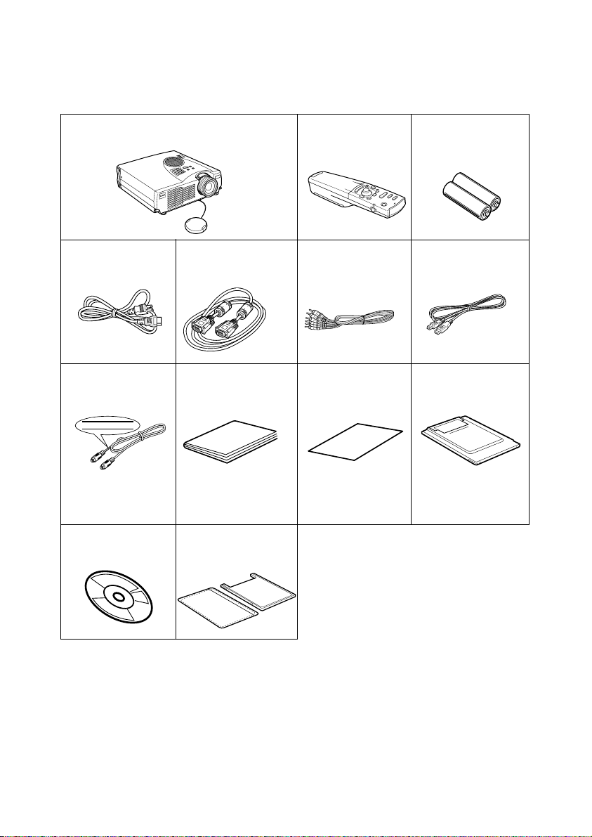
Accessory Verification
Check to confirm that the following items are included in the package when removing the projector and accessories from the box. Contact your dealer if any items are found to be missing.
·Projector
Lens Cover with string
· Power Cord · Computer Cable
(mini D-Sub 15pin/
mini D-Sub 15pin)
· PS/2 Mouse Cable · Owner’s Manual
(this document)
PS/2 MOUSE
· Remote Control · 2AA Batteries for
the remote control
(three-cell alkaline batteries)
· RCA Audio Cable
· USB Mouse Cable
(Red/White/Yellow)
·Temporary
Wa rr a n t y
·Memory Card Set
(8Mbyte compact flash
card + PC card adapter)
*The memory set
has been inserted
into the projector.
·EasyMP Software
(CD-ROM)
· Dummy card
(Dummy card and card
case)
Page 3
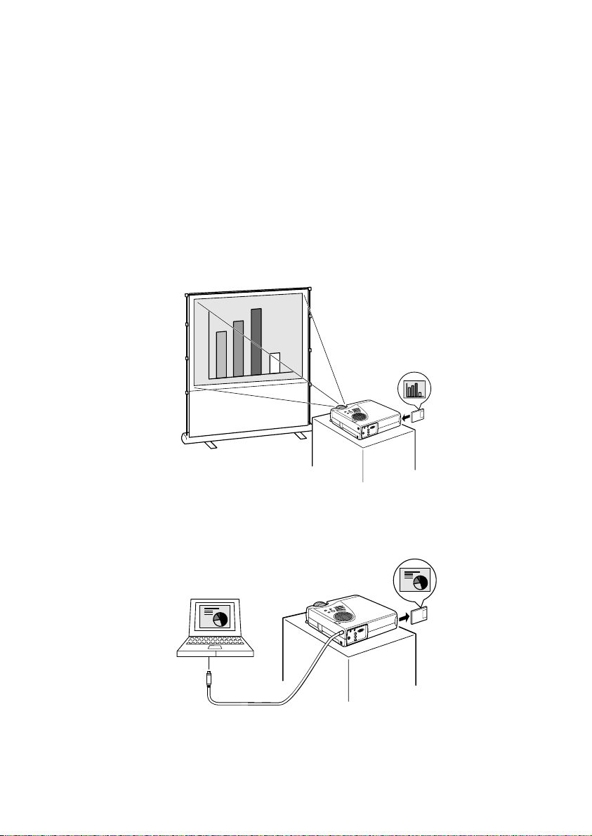
■■■■ Features
● Crystal clear screen
Clarity has been vastly improved.
Provides crystal clear projections even in bright areas, perfect for presentation purposes.
● Wide range of display resolution
Uses a newly-developed high resolution liquid crystal panel.
(1024×768)
● Compact and light
A compact body makes it easy for carrying around.
(approximately 2.7Kg, 6 litres)
● Supports the D output port
Supports digital tuners up to D4 ratings.
● Mounting the PCMCIA card slot
The data saved onto the memory card can be projected for presentation purposes.
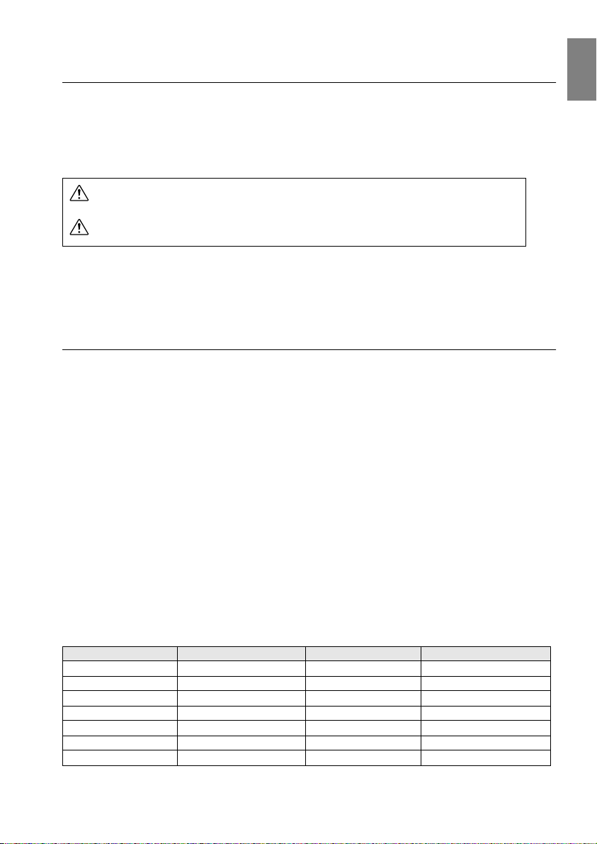
● USB port mounted
In addition to enabling the use of a USB mouse, this also allows data to be transmitted to the
projector's memory card when connected to a computer (only when a list of files is displayed
with EasyMP.)
Features - 1
Page 4

■■■■ Contents
Features 1
Using this manual 7
Symbol displays ................................................................... 7
Power cords for use abroad .................................................7
Safety Precautions 8
Before Using This Equipment 13
Parts, Names and Operations 13
Projector ............................................................................. 13
Remote Control .................................................................. 17
Range of Remote Control Operations ................................20
Inserting the Remote Control Batteries .............................. 21
Installation 22
Installation Procedure 22
Screen size and projection distance .................................. 23
Projection angles ................................................................24
Connections 25
Connecting the projector to a computer 25
Eligible computers .............................................................. 25
In the case of the mini D-Sub 15 pin .................................. 27
Sound connection .............................................................. 28
Connecting external audio equipment ................................ 29
Connecting up the mouse (wireless mouse function) ........30
2- Contents
Page 5

Connecting the video equipment 32
In the case of composite image signals ............................. 32
In the case of S image signals ........................................... 32
In the case of component
(color differential*) image signals ....................................... 33
In the case of the digital tuner's D output port ................... 34
Projecting 35
Projection 35
Preparations ....................................................................... 35
Commencing projection ..................................................... 37
Ending 40
Adjusting the Projection Position 43
Feet adjustments ............................................................... 43
Adjusting the Projection Size 44
Zoom adjustment ............................................................... 44
Keystone adjustment ......................................................... 45
Picture Quality Adjustment 46
Focus adjustment ............................................................... 46
Auto adjustment (when projecting computer images) ........ 46
Tracking adjustments
(when projecting computer images) ................................... 47
Synchronization adjustments
(when projecting computer images) ................................... 47
Introduction of Functions 48
Useful Functions 49
Useful Functions 49
Contents- 3
Page 6

Help Function ..................................................................... 49
Projection Cutting 51
A/V Mute Function ..............................................................51
Freeze Function ................................................................. 51
Switching Image Sizes 52
Enlarging Images (E-zooming function) 54
Effect Function 55
Cursor/Stamp .....................................................................55
Box ..................................................................................... 56
Spotlight ............................................................................. 57
Bar ..................................................................................... 58
Cancelling effects ............................................................... 58
P in P Function 59
Adjustment and Settings 60
Volume Adjustment 60
Menu Configuration 61
Menu items .........................................................................61
Menu Operations 63
Operation method .............................................................. 63
Setting items ......................................................................65
Image capture ....................................................................69
User logo registration ......................................................... 71
Using the EasyMP Function 73
4- Contents
Page 7

Function description 73
Inserting the memory card 74
Viewing EasyMP files 76
Switching projected images across to EasyMP ................. 77
Operations on the file list display ....................................... 78
Operating scenarios 82
Playing back scenarios ...................................................... 82
Editing scenarios ................................................................ 83
Creating scenarios 86
Install the EasyMP Software .............................................. 86
Creating scenarios ............................................................. 87
Transmitting scenarios ....................................................... 91
Connecting up computer with USB cables 93
Connections and installation of the USB driver .................. 93
Browsing the memory card from the computer .................. 94
Troubleshooting 96
Troubleshooting 96
Operation Indicator ............................................................ 96
Lamp Indicator ................................................................... 97
Temperature Indicator ........................................................ 98
When the Indicators Provide No Help 99
The image is not projected ................................................. 99
The image is unclear ........................................................ 103
The image is cut up (Large)/Small ................................... 104
The image color is bad ..................................................... 105
The image is dark ............................................................ 105
No sound .......................................................................... 106
The remote control will not work ...................................... 106
Contents- 5
Page 8

The projector will not switch off
(after the [Power] button has been pressed) .................... 107
Problems with EasyMP images ........................................ 107
Problems when using the EasyMP Software ...................107
Maintenance 108
Cleaning the Projector, Cleaning the Lens,
Cleaning the Air Filter 108
Cleaning the projector ......................................................109
Cleaning the lens ............................................................. 109
Cleaning the Air Filter ....................................................... 109
Replacing the Air Filter 110
Replacement method ....................................................... 110
Replacing the Lamp 111
Replacement method ....................................................... 112
Others 114
Optional Parts 114
Transportation 115
Terminology 116
Specifications 118
Check Sheet 119
World-Wide Warranty Terms 121
Index 125
6- Contents
Page 9
■■■■ Using this manual
Symbol displays
A variety of picture displays have been used in this manual and on the actual product to ensure
that the projector is used correctly and safely in order to prevent risks to users and other people,
and to prevent damage to property. Explanations for these displays are provided below. Ensure
that they are fully understood before reading this manual.
Wa rn in g
Caution
Point: Includes supplementary explanations and useful tips.
See page: Indicates reference pages
*: Refer to the terminology
· Usage of the terms“this unit” and “this projector” in this manual
The terms “this unit” and “this projector” appear regularly in this manual, and these
terms also cover the accessories supplied with the projector and other optional products.
Displays details that may result in death or injury if
ignored.
Displays details that may result in injury or damage to
property if ignored.
Power cords for use abroad
The power cable supplied with the projector conforms to the Electrical Appliance and Material
Control Law and may also be used in Japan.
Ensure that power cords that conform to local laws are used when using the projector in overseas
countries.
Contact one of the numbers on the International Assurance Contact List for details on purchasing
power cables.
● General overseas conditions
The following conditions are common to all countries.
1. The power cord must be a three-core cord (with earth included) that contains the
authorization mark of the authorization organization of the country in which the
projector is to be used.
2. The power cord must have a minimum permissible current of 7A, an official rated
voltage of 125V, or an alternating current of 250V.
3. The power cord must be less than 4.5m in length.
4. The coupler (the connector for connecting to the projector, not the plug for use with a
wall-mounted socket) must conform to EN60320/IEC 320 rated inlets (standard sheet
C13.)
● Authorization organizations in each country
Country name Authorization organization Country name Authorization organization
America UL Sweden SEMKO
Canada CSA Denmark DEMKO
Great Britain BSI Germany VDE
Italy IMQ Norway NEMKO
Australia EANSW Finland FIMKO
Austria OVE France UTE
Switzerland SEV Belgium CEBC
Note: The cords for America and Canada must be three-core SJT or SVT type cords.
Using this manual - 7
Page 10
■■■■ Safety Precautions
d
Read and observe the following safety precautions to ensure safe use of the equipment.
Wa rn in g
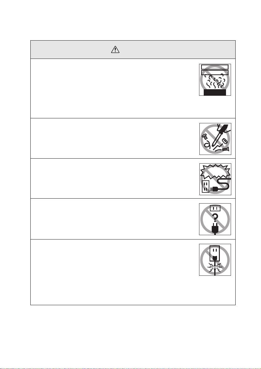
●
If any of the following abnormalities occur, switch off the power
supply immediately, remove the plug from the power socket and
contact your dealer or nearest address provided at page 121.
· The emission of smoke, strange odours or strange noises.
· When water or foreign objects have entered the inside of the unit.
· When the unit has been dropped or the case damaged.
Continuation of operations under these conditions may result in the
outbreak of fire or electric shocks.
Repairs should never be attempted by the user.
●
The cabinet to the unit should never be opened by anyone other
than our service personnel.
The inside of the projector contains many high-voltage parts that may
result in the outbreak of fire, electric shocks or other incidents.
●
Never use an electrical voltage other than that displayed.
The use of a voltage other than that specified may result in the outbreak of fire or electric shocks.
Abnormi oder
Abnormi noise
Other than
those specifie
●
Verify the specifications of the Power Cord.
The Power Cord supplied with the projector conforms to the electrical
specifications of the country of purchase. If the projector is to be used
in any other location, check the electrical voltage and shape of sockets in the relevant country beforehand and purchase a cable that conforms to that country’s specifications.
●
Never use damaged Power Cord.
Failure to observe this may result in the outbreak of fire or electric
shocks.
Also ensure that the following points are strictly observed.
· Never make any modifications to the Power Cord.
· Never place anything heavy on the Power Cord.
· Never bend, twist or pull the cable.
· Ensure that the cable is not installed near heaters.
Contact your dealer or nearest address provided at page 121 if the
power cord becomes damaged.
8 - Safety Precautions
Page 11
Wa rn in g
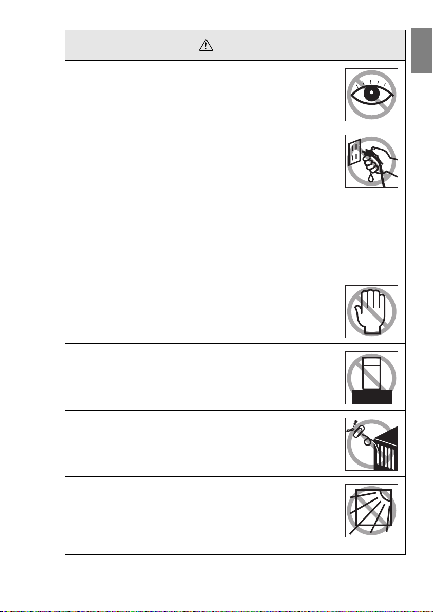
Never look into the lens when the power is switched on.
●
An extremely strong light is emitted that may cause sight defects.
Special attention must be paid by households with children.
Take care when handling power plugs and power connectors.
●
Failure to observe these instructions may result in the outbreak of fire
or electric shocks.
Observe the following precautions when handling power plugs and
power connectors.
· Never connect too many appliances to a single socket.
· Never use plugs or connectors to which dust, dirt or other foreign
objects have adhered.
· Ensure that the plugs and connectors are firmly inserted as far as
they will go.
· Do not atempt to plug in plugs or connectors with wet hands.
· Do not pull the Power Cord when disconnecting plugs and connec-
tors. Always ensure that the actual plug or connector is firmly
gripped.
The projector includes many glass parts, such as the lens and
●
lamps.
If any of these parts should break, handle them with extreme care to
avoid injury and then contact your dealer or nearest address provided
at page 121 and request repairs.
Never place vases or containers that contain liquid on top of the
●
projector.
If the water is spilt and enters the outer case, it may result in the outbreak of fire or electric shocks.
Never insert or drop metal or inflammable objects, or any other
●
foreign objects into the suction inlets and ventilation outlets on
the projector.
Failure to observe this may result in the outbreak of fire or electric
shocks.
Never place the projector or the battery-operated remote control
●
in locations with excessive temperatures, such as in vehicles
with closed windows, in areas subject to direct sunlight, or near
the fan outlets of air-conditioners and heaters.
Failure to observe this may result in heat-distortion that would have
an adverse affect on the contents of the projector, and may result in
the outbreak of fire or electric shocks.
Safety Precautions - 9
Page 12
Caution
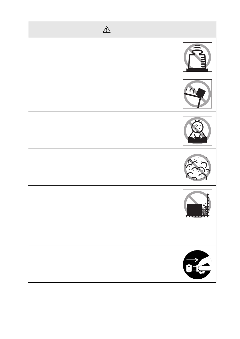
Never stand on the projector or place any heavy objects on it.
●
Failure to observe this may result in it dropping over, becoming damaged, or causing injury.
Never place the projector on unstable surfaces, such as wobbly
●
tables or slanted surfaces.
Failure to observe this may result in it dropping over, becoming damaged, or causing injury.
Do not place or store the projector within the reach of children’s
●
hands.
Failure to observe this may result in it dropping over, becoming damaged, or causing injury.
Do not place the projector in humid or dusty locations, or in
●
locations where it would be subject to oil steam or water steam,
such as kitchens or near humidifiers.
Failure to observe this may result in the outbreak of fire or electric
shocks.
Never block the projector’s suction inlets or ventilation outlets.
●
Failure to observe this may result in the build up of high temperatures inside the projector, leading to the outbreak of fire. Do
not place the projector in the following locations.
· In narrow, badly ventilated areas, such as in cupboards or in bookcases.
· On top of carpets, matresses or blankets.
· Never cover the projectors with table cloth or other material.
Also, if placing by a wall, ensure that at least 20cm of space has
been provided between the projector and the wall.
Never attempt to remove the lamp immediately after use. Wait
●
for approximately one hour after the power has been cut off to
allow the lamp sufficient time to cool.
Failure to observe this may result in the outbreak of fire.
10 - Safety Precautions
Page 13
Caution
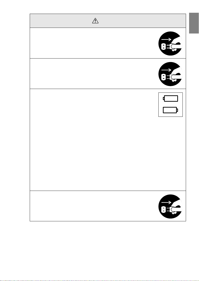
Always ensure that the power has been switched off, the plug
●
has been disconnected from the power socket, and all other
cables have been disconnected when moving the projector.
Failure to observe this may result in the outbreak of fire or electric
shocks.
Never attempt to remove the lamp immediately after the projec-
●
tor has been used. Wait for the projector to cool down sufficiently by leaving it for at least sixty minutes after the power
supply has been switched off before attempting this.
Failure to observe this may result in burns or other injuries.
Misuse of the batteries may result in damage to the batteries
●
and subsequent leakages, leading to the outbreak of fire, injury
and product corrosion. Observe the following precautions to
ensure safety.
· Never use combinations of different batteries, or old batteries
together with new batteries.
· Never use batteries that are not specified in the instruction manual.
· If liquid should leak from the battery, wipe up the leakage with a
cloth and then replace the battery accordingly.
· Replace the batteries immediately when the time for replacement
arrives.
· Remove the batteries when the projector is not to be used for a long
period of time.
· Never apply heat to the batteries, or place them in naked flames or
water.
· Ensure that the batteries are inserted in accordance with the correct polarity (+ and -).
· If any liquid that has leaked from a battery gets onto the hands,
wash it off immediately with water.
Batteries must be disposed of in accordance with the regulations in
effect in each relevant area.
Ensure that the electric plug and connectors have been discon-
●
nected from their sockets when performing maintenance tasks.
Failure to observe this may result in electric shocks.
Confirmation
Safety Precautions - 11
Page 14

Safety Precautions
Using the projector outside of the permissible temperature range (+5C° to +35C°)
●
may result in unstable display and excessive loads being placed on the fan, leading to damage to the equipment.
Storing the projector outside of the permissible temperature range (-10C° to
●
+60C°) may result in damage of the case. Take special care to avoid placing the
equipment in direct sunlight for a long period of time.
Do not use the projector with the lens cover still in place. The heat generated by
●
the lens may cause the cover to become malformed.
The liquid crystal display panel has been manufactured with high-accuracy tech-
●
nology and contains more than 99.99% active pixels. However, note that there is a
possibility of 0.01% of missing pixels and pixels that will be constantly illuminated.
12 - Safety Precautions
Page 15
Before Using This Equipment
This section provides explanations on parts and part names, and the items that should be
verified before operating the remote control.
■■■■ Parts, Names and Operations
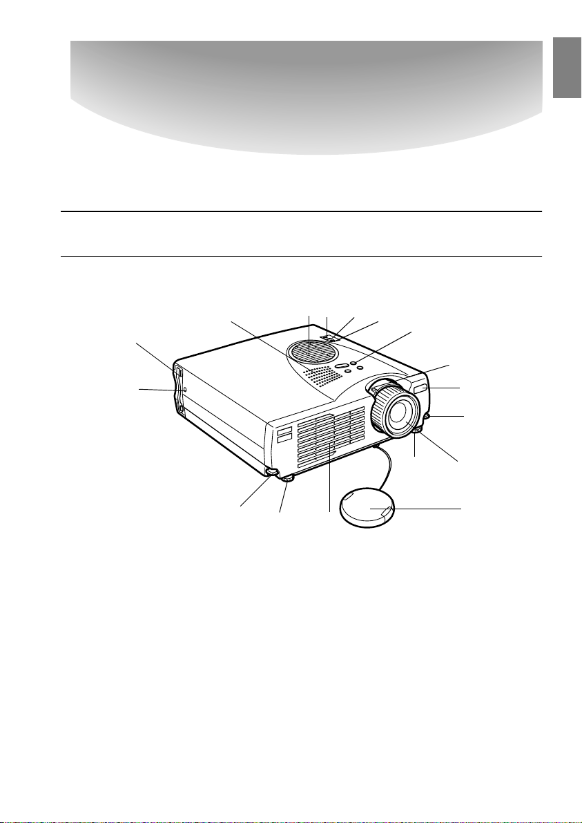
Projector
● Front Panel
4
6
7
8
5
3
2
1
15
14
9
9
1 Operation Panel
2 Operation Indicator
3 Lamp Indicator
4 Temperature Indicator
5 Air Filter (ventilation inlet)
6 Speaker
7 PCMCIA Card Access Lamp
8 PCMCIA Card Slot
9 Foot Adjust Lever
10 Front Foot
11 Ventilation Outlet
12 Lens Cover
13 Focus Ring
14 Remote Control Receiver
15 Zoom Lever
10 11
10
13
12
Parts, Names and Operations - 13
Page 16
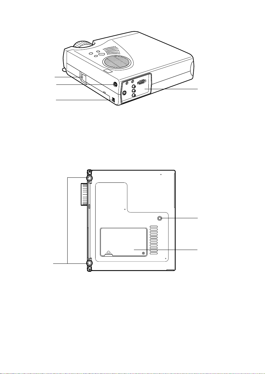
● Rear surface, Side surface
1
2
3
1 Power Inlet
2 Mouse/Com Port
3 USB Port
4 I/O Port
● Rear Panel
4
1
1 Front Foot
2 Rear Foot
3 Lamp Cover
14 - Parts, Names and Operations
2
3
Page 17

● Operation panel (on top of the projector)
Power
1
Help
2
Keystone
Source
3
Enter
Select
1 [Power] button (see page 37, 40 )
Switches the power supply on and off.
· Press twice to switch off the power supply.
2 [Help] button (see page 49)
Displays the methods of solving problems. Press this button when trouble occurs.
3 [Source] (Enter) button (see page 38, 50)
· The projected images will be switched sequentially between Computer (component) -->
S-Video --> Composite Video --> EasyMP. S-Video will not be displayed when no S-Video
signals are being input. EasyMP will not be displayed when a memory card has not been
inserted.
· Operates as an [Enter] button (to set selections) when the help text is displayed.
4 [Keystone] (Select) button (see page 45)
· Performs the necessary adjustments when the screen distorts into a trapezoid shape.
· This button functions as the [Select] button (vertical selection) when the help screen is
displayed.
4
Parts, Names and Operations - 15
Page 18
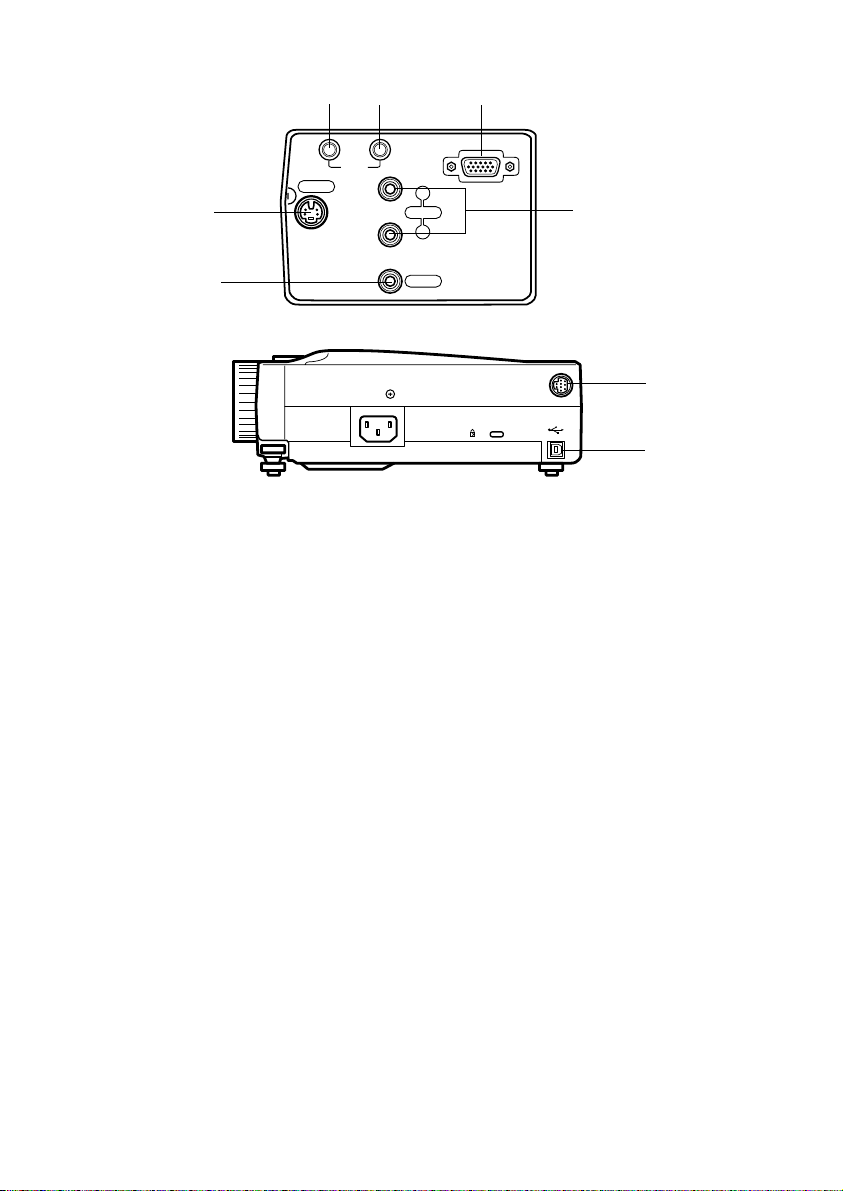
● I/O Ports
32 1
Computer/
Component Video
InOut
Audio
S-Video
4
Audio
R
5
L
6
Video
Mouse/Com
7
8
1 Computer / Component Video Port
Inputs computer analog image signals and AV equipment component image signals.
2 Audio In Port
Inputs the sound signals from equipment connected to the Computer #1 port. Use a stereo
mini-jack when making the connection.
3 Audio Out Port
Outputs the projector's sound signals.
· The sound will no longer be output from the projector's speakers when a stereo mini-jack
is connected here.
4 S-Video Port
Inputs the video equipment's S image signals.
5 L-Audio-R Port
Inputs the sound signals from A/V equipment connected to the Video port or the S-Video
port. The connection is established with an RCA pin jack.
Only the sound for connected computers or A/V equipment is output.
6 Video Port
Inputs the A/V equipment’s component image signals.
7 Mouse/Com Port
Connected to the computer when the remote control is to be used as a wireless mouse.
8 USB Mouse Port
Connect up the computer with the USB mouse cable when the remote control is to be used
as a wireless mouse. Connect up the computer with the USB cable when data is to be
transferred from the computer to the projector's memory card.
16 - Parts, Names and Operations
Page 19
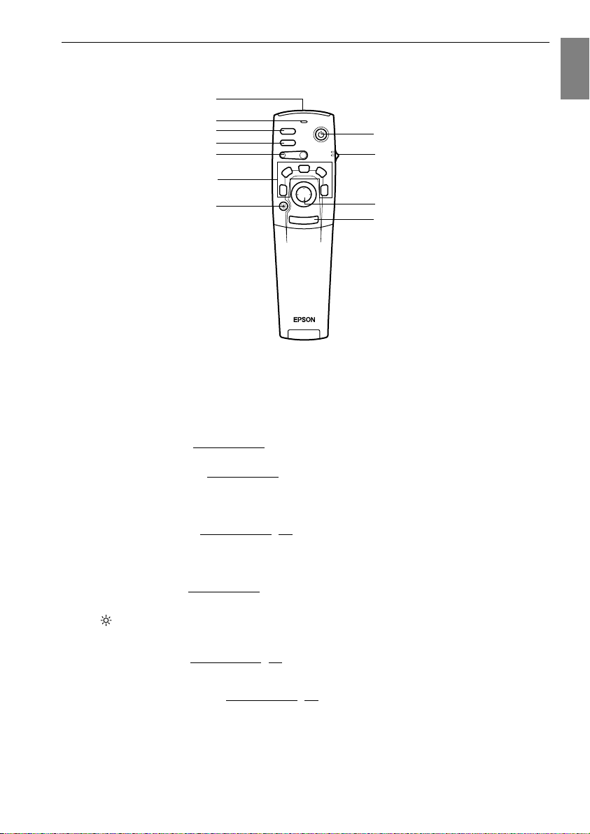
Remote Control
● Front Panel
1
2
3
4
5
6
7
1 Remote control light-receiving area
Outputs the remote control unit’s signals.
2 Indicator
Illuminated when the remote control unit signals are being output.
· Light will not be emitted when the batteries are getting low or when the [R/C ON OFF]
switch is set at [OFF].
3 [Freeze] button (see page 51)
Temporarily freezes the image. Press this button once more to cancel the freeze mode.
4 [A/V Mute] button (see page 51)
Temporarily mutes the images and sound. To resume projection, press the button once
more, adjust the volume control, or display the menu.
It is also possible to project the user logo when the A/V mute function is operating.
5 [E-Zoom] button (see page 54, 59)
Enlarges and reduces the size of the image. The image in the sub-screen will be enlarged
when Picture-in-Picture images are being projected. Press the [Esc] button to cancel this
function.
6 [Effect] button (see page 55)
Executes the allocated effect function. Press the [Esc] key to cancel this mode.
7 [ (Light)] button
The remote control button will be illuminated for approximately ten seconds.
8 [Power] button (see page 37, 40)
Switches the power supply to the projector on and off.
9 [R/C ON OFF] switch (see page 37, 41)
Switches the remote control unit on and off. The remote control unit cannot be used for
operations when this switch is not set at [ON].
Freeze
A/V Mute
E-Zoom
2
1
Power
R/C ON
OFF
3
4
5
Enter
8
9
10
Esc
11
Parts, Names and Operations - 17
Page 20
10 [Enter] button (see page 31, 63)
· Sets the menu item when pressed, and then moves onto the lower stage. Becomes a cursor key to select the menu items when moved up, down, left or right.
· This function operates as a left-hand click on the mouse when computer images are being
projected. The pointer will move when this button is moved up, down, left or right.
11 [Esc] button (see page 31, 64)
· Ends the function being used. Returns to the previous stage when the menu or help text is
being displayed.
· This function operates as a right-hand click on the mouse when computer images are
being projected.
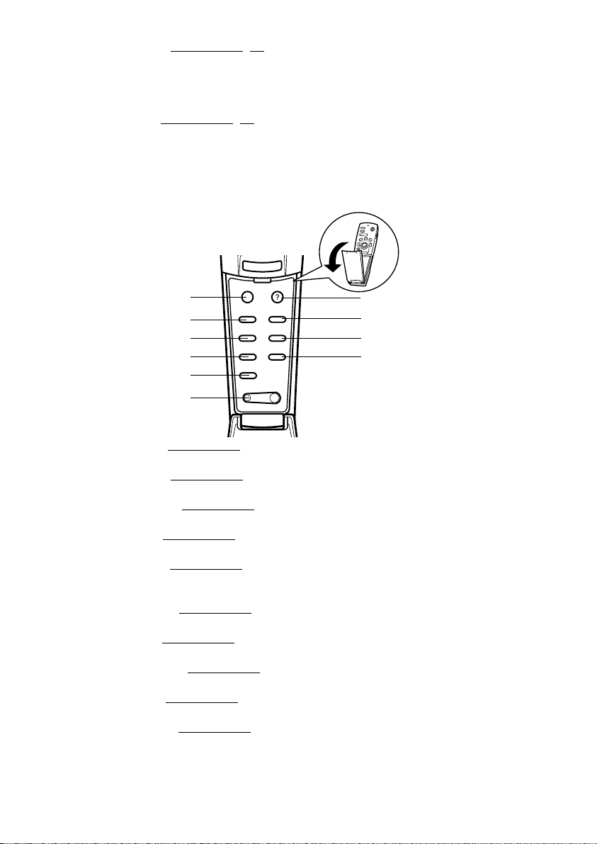
● Inside of the Cover
Enter
Esc
- Volume +
Help
EasyMP
Video
Resize
5
7
8
9
10
1
1
2
3
4
5
6
Menu
Comp
S-Video
Auto
P in P
1 [Menu] button (see page 63)
Displays and ends the menu.
2 [Comp] button (see page 38)
Switches across to the image from computer port.
3 [S-Video] button (see page 38)
Switches S-video images (S-Video).
4 [Auto] button (see page 46)
Optimizes the computer image.
5 [P in P] button (see page 59)
Displays the video image within the computer image or the video image as a sub-screen.
This function is cancelled by pressing this button once again.
6 [Volume] button (see page 60)
Adjusts the volume.
7 [Help] button (see page 49)
Displays the method of solving problems. Press this button when trouble occurs.
8 [Easy-MP] button (see page 38)
Switches the memory card data across to the projected Easy-MP images.
9[Video] button (see page 38)
Switches across to the video images.
10 [Resize] button (see page 52)
Switches between the window display and the resizing display when computer images are
being projected. Switches the aspect ratio between 4:3 and 16:9 when video images are
being projected.
18 - Parts, Names and Operations
Page 21
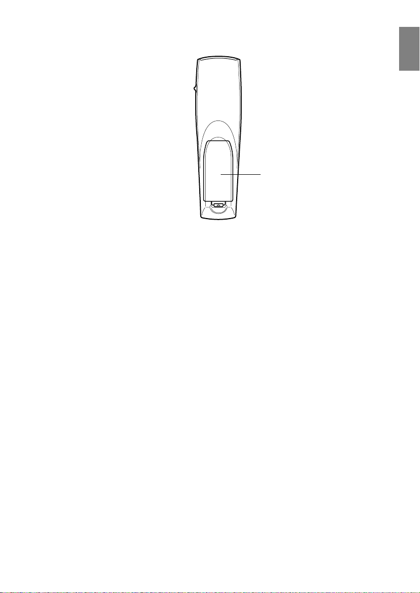
● Rear Panel
1 Battery Cover
1
Parts, Names and Operations - 19
Page 22
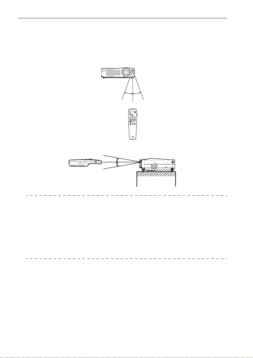
Range of Remote Control Operations
Depending on the distance and angle from the main unit’s light receiving area, there are cases
where the remote control will not function. Ensure that the remote control is used within the following conditions:
● Operable distance: Approximately 10 metres
● Operable range:
Approximately 30 degrees to
the left and right
Approximately 15 degrees up and down
Mouse/Com
Point
· Ensure that the [R/C ON OFF] switch is set at [ON] when using the remote control unit.
· Aim the remote control at the projector’s light-receiving area.
· There are cases where the operable distance (approximately 10 meters) of the remote
control is diminished when signals are reflected off screens depending on the type of
screen in use.
· Ensure that sunlight and florescent lighting is not shining directly into the projector’s light-
receiving area.
· If the remote control will not function or malfunctions, there is a possibility that the batteries need changing. In this event, replace the batteries accordingly.
20 - Parts, Names and Operations
Page 23
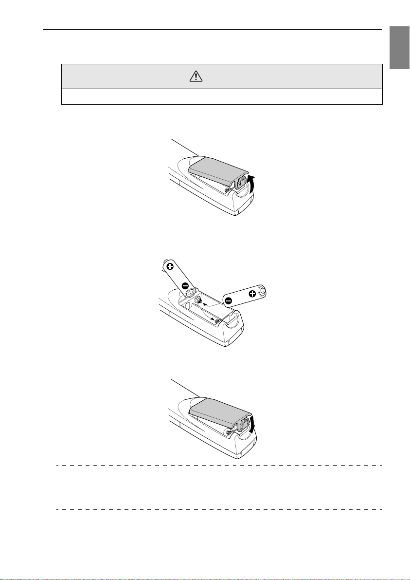
Inserting the Remote Control Batteries
The remote control batteries are inserted in accordance with the following procedure:
Caution
Ensure that unused batteries of the same type are used.
Remove the Battery Cover.
1
Apply pressure to the clip holding the Battery Cover, and then lift it upwards.
Insert the batteries.
2
Ensure that the batteries are aligned correctly with the “+” and “-“ labels on the remote
control.
Replace the cover.
3
Apply pressure to the battery cover until it clicks firmly into place.
Point
· Specified batteries: Phase-3 alkali dry-cell batteries (LR6) X 2
· The batteries should be replaced approximately once every three months when used for
thirty minutes per day.
Parts, Names and Operations - 21
Page 24
Installation
This section provides an example of projector installation, and explanations on the projection distances and projection angles.
■■■■ Installation Procedure
This section provides an example of projector installation, and explanations on projection distances and angles.
Caution
· Do not block the ventilation outlet on the front of the projector, or the air filter (suction
inlet) on the top.
· Take note that there is a possibility that pieces of cloth or paper may be sucked into the air
filter on the top of the projector during projection.
· Do not place the projector in a location where it is subject to the direct air flow from air conditioners or heaters.
· When the projector is to be placed near a wall, ensure that there is at least 20cm of space
between the wall and the projector.
· Do not cover the projector with table cloths or other material.
22 - Installation Procedure
Page 25
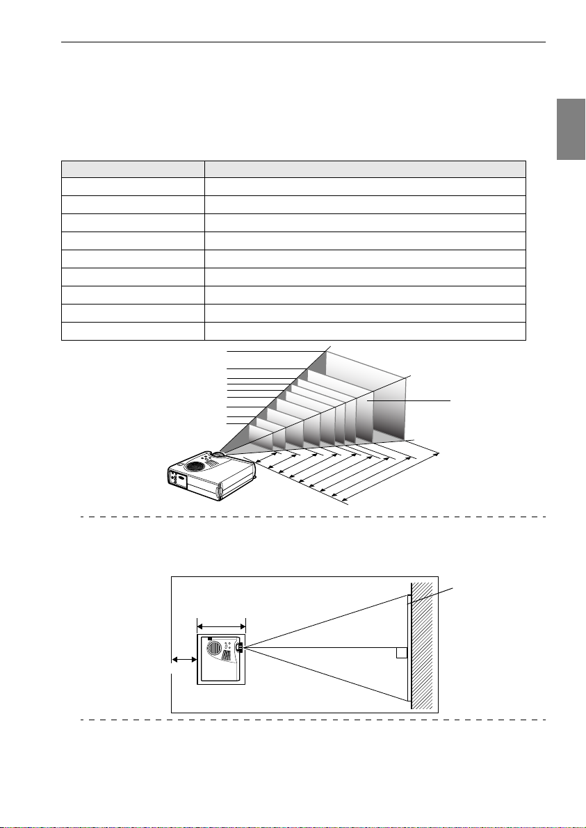
Screen size and projection distance
S
Determines the distance that the screen must be from the lens in order to obtain the required
screen size.
The projector’s Standard Lens is approximately a 1.2x zoom lens and the largest screen size is
about 1.2 times the size of the smallest screen.
Using the following table for reference purposes, install the projector so that the screen size is
smaller than the screen.
Screen Size Approximate Projection Distance
2
2
2
0
0
X
1
5
0
2
0
c
m
1.1m to 1.3m
1.5m to 1.8m
2.2m to 2.7m
3.0m to 3.7m
3.8m to 4.6m
4.6m to 5.4m
5.7m to 6.9m
7.6m to 9.2m
11.5m to 13.9m
4
1
0
X
3
0
0
c
3
0
5
X
2
2
9
c
4
m
X
1
8
3
c
m
c
m
6
1
0
X
4
6
0
c
m
m
Center of the lens
30-inch (61
40-inch (81
60-inch (120
80-inch (160
100-inch (200
120-inch (224
150-inch (305
200-inch (410
300-inch (610
creen Size
46cm)
×
61cm)
×
90cm)
×
120cm)
×
150cm)
×
183cm)
×
229cm)
×
300cm)
×
460cm)
×
300-inch
200-inch
150-inch
120-inch
100-inch
80-inch
60-inch
40-inch
30-inch
1
6
0
X
1
1
2
0
X
9
0
c
m
8
1
X
6
1
c
m
6
1
X
4
6
c
m
1.8
1.1 - 1.3
-
2.7
-
1.5
3.7
2.2
-
4.6
3.0
-
5.4
3.8
4.6 -
6.9
-
5.7
13.9m
9.2
-
11.5 -
7.6
Distance from the projector
Point
· The screen size will become smaller when the trapezoid correction function is used.
· Install the projector at least 20cm away from the wall
213mm
20cm or more
This distance is the
projection distance.
.
Screen
Installation Procedure - 23
Page 26
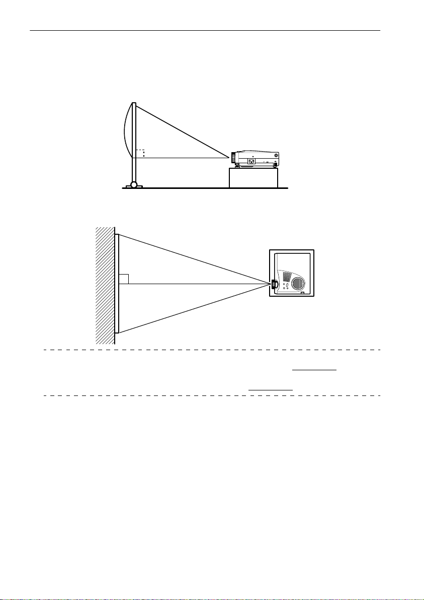
Projection angles
The optimum projection screen is acquired by placing the center of the projector’s lens and a
right-angle to the screen.
When viewing from the side
* It is possible to move the projection position up and down with the lens shift function
Mouse/Com
A:B 10:Becomes 0
When viewing from the top or bottom
Point
Although the projection angle can be adjusted with the front foot (see page 43), there are
cases where the screen will distort into a trapezoid shape. In this event, adjust the trapezoid distortion with the trapezoid correction function. (see page 45
)
24 - Installation Procedure
Page 27
Connections
This section provides explanations on connecting the projector to computers and video
equipment.
■■■■ Connecting the projector to a computer
Switch off the power supply to the projector and computer before attempting to make the
connection.
Eligible computers
There are computers with which connections cannot be established and computers that cannot
be used for projection purposes even though a connection has been established. First of all, it is
necessary to confirm that a connection can be established with the computer in use.
● Conditions for eligible computers
Condition #1: The computer must be fitted with an image signal output port.
Check to ascertain that the computer is fitted with ports that will output image signals,
such as the [RGB Port], the [Monitor Port] and the [Video Port]. If you have trouble
confirming this, refer to chapter on external monitor connections in the computer’s
instruction manual.
There are computers, such as combined computer/monitor models and laptop models,
that do not allow connections or for which optional external output ports must be
purchased.
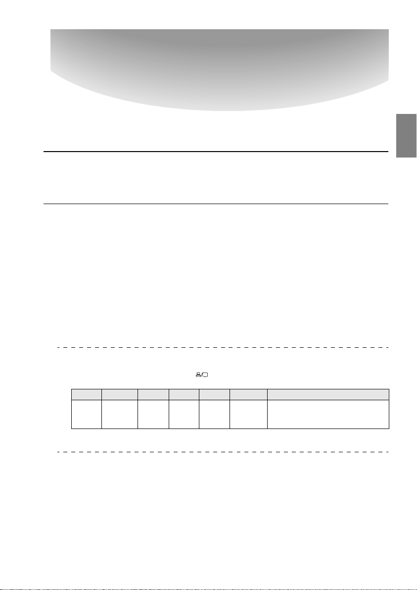
Point
Depending on the computer, there are cases when it is necessary to switch the image signal output with the connection key ( , etc.,) and the settings.
NEC Panasonic To s hi b a IBM SONY FUJITSU Macintosh
Fn+F3 Fn+F3 Fn+F5 Fn+F7 Fn+F7 Fn+F10 Mirroring is set up with monitor
The table shown above provides examples for certain products. Refer to the computer’s
instruction manual for further details.
adjustments on the control panel after
starting up.
Connecting the projector to a computer - 25
Page 28

Condition #2: The resolution and frequency of the computer must be within the
boundaries listed in the chart on the next page.
Projection will not be possible if the computer does not support the output image signal
resolutions and frequencies shown in the chart on the next page (there are cases where
projection is possible, but vivid projection will not be possible).
Confirm the image signal resolution and frequency with the computer’s instruction
manual.
There are also computers available that allow the output resolution to be amended. In this
case, amend the parameters to fit within the ranges shown in the chart on the next page.
Signal Refresh Rate
VGAEGA
VGA 60
VGA Text
VESA 72/75/85
SVGA 56/60/72/75/
XGA 43i/60/70/75/
SXGA 70/75/85
SXGA 60/75/85
SXGA 43i/60/75/85
*1
UXGA
MAC13
MAC16
MAC19
MAC21
NTSC
PA L
SECAM
SDTY
(480i/P)
HDTV
(720P)16:9
HDTV
(1080i)16:9
*1
The EMP-505 is not compatible with UXGA.
(Hz)
85
85
60
60
Resolution
(Dots)
640
640
720
720
640
800
1024
1152
1280
1280
1600
640
832
1024
1152
Pixels (dots)
Used During
Resizing Dis-
play (Resize
350 1024×560 640×350
×
480 1024×768 640× 480
×
350 1024× 640 720× 350
×
400 1024× 640 720× 400
×
480 1024×768 640×480
×
600 1024×768 800×600
×
768 1024×768 1024× 768
×
864 1024×768 1152× 864
×
960 1024×768 1280×960
×
1024 960×768 1280×1024
×
1200 1024×768 1600×1200
×
480 1024×768 640×480
×
624 1024×768 832×624
×
768 1024×768 1024×768
×
870 1016×768 1152×870
×
Pixels (dots)
Used During
Real Display
(Resize Off)
768 1024×576 4:3
768 1024×576 4:3
768 1024×576 4:3
768 1024×576 4:3
576
1024
1024
1024
1024
1024
On)
×
×
×
×
×
Remarks
Virtual (Partial) Display
Virtual (Partial) Display
Virtual (Partial) Display
Virtual (Partial) Display
Virtual (Partial) Display
16:9, Selectable
↔
16:9, Selectable
↔
16:9, Selectable
↔
16:9, Selectable
↔
26 - Connecting the projector to a computer
Page 29
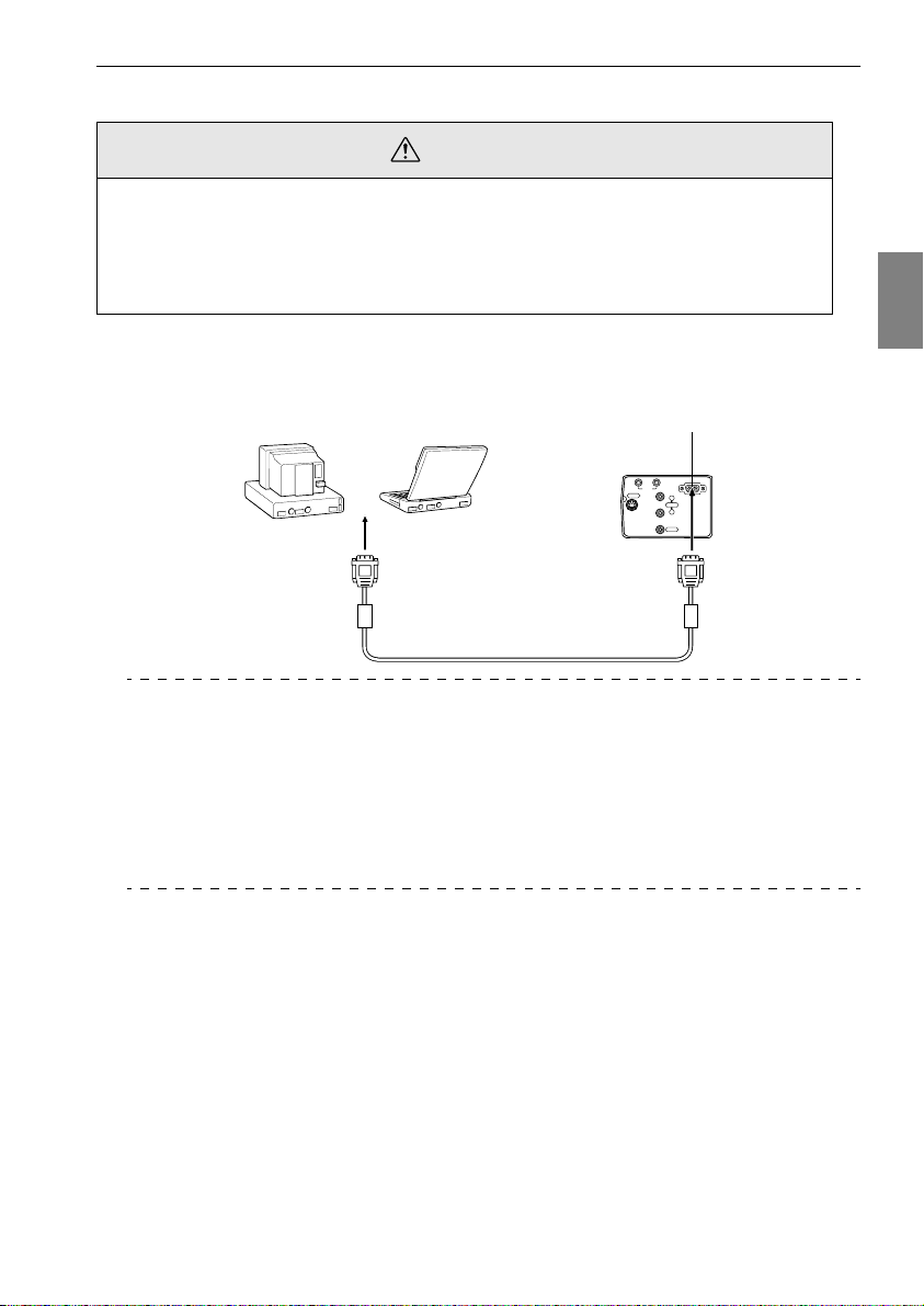
In the case of the mini D-Sub 15 pin
Caution
· Switch off the power supply to the projector and computer before attempting to make the
connection. Failure to observe this may result in damage.
· Confirm the shape of the cable connector and the shape of the port before making the connection. Applying excessive force when the direction or shape of the connector and port
differ may result in defects and damage to the equipment.
· Connect the computer's monitor port to the projector's Computer/Component Video port
with the computer cable supplied.
● When the monitor port is the D-Sub 15 pin
Computer/Component Video port
Computer/
Component Video
InOut
Audio
S-Video
R
Audio
L
Monitor port
(video port)
Computer Cable
(supplied with the projector)
Point
· Set the input signal parameter on the image menu to [RGB] once the connection has
been established.
· Do not bunch the power cable and the computer cable together. Failure to observe this
may result in noise appearing in the images, and may cause malfunctions.
· An adapter may be required when making the connection depending on the stand of the
computer’s port. Refer to the computer instruction manual for further details.
· An optional MAC desktop adapter (ELPAP01) is required when connecting up to a Macintosh computer.
Video
Connecting the projector to a computer - 27
Page 30
● When the monitor port is 13w3
The Computer/Component Video port is also connected to the D-Sub 15 port with the use of
the conversion cable when the 13w3 port is used for connecting the computer’s monitor port to
a work station.
· Connect the computer's monitor port (13w3) to the projector's Computer/Component Video
port with a 13w3 <--> D-Sub 15 cable (available on the open market).
Monitor port
Computer/Component Video port
Computer/
Component Video
InOut
Audio
S-Video
R
Audio
L
Video
(available on the open market)
13w3 Cable
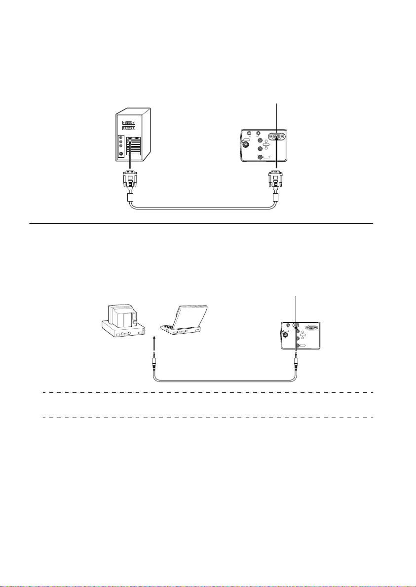
Sound connection
The projector is equipped with a single speaker capable of outputting a maximum of 1W, and it
is possible to output computer sound from the projector's speaker. Connect the computer's
Audio Out port to the projector's Audio In port (stereo mini-jack) with an audio cable (available on the open market).
Computer audio output port
(available on the open market)
Audio Cable
Point
The audio signals output the selected image’s sound.
Audio In port
Component Video
InOut
Audio
S-Video
R
Audio
L
Video
Computer/
28 - Connecting the projector to a computer
Page 31

Connecting external audio equipment
It is possible to enjoy dynamic sound by connecting the Audio Out port on the projector to a
PA system, an active speaker system, or other speakers equipped with built-in amplifiers.
External audio equipment
Audio connection cable (available on the open market)
Use audio connection cables available on the open market (pin plug <--> 3.5mm stereo minijack plug).
Point
· The sound will be output externally if a stereo mini-jack is inserted into the Audio Out port.
The sound will not be emitted from the projector's speakers at this time.
· The sound on the images being projected will be output.
· Purchase an audio connection cable that matches up with the connector on the external
audio equipment to be used.
Audio Out port
InOut
Audio
S-Video
Computer/
Component Video
R
Audio
L
Video
Connecting the projector to a computer - 29
Page 32

Connecting up the mouse (wireless mouse function)
This enables the computer’s mouse pointer to be operated with the remote control in the same
way as a wireless mouse.
Connect the computer's mouse port to the projector's Mouse/Com port or USB mouse port
with the mouse cable.
Computer Mouse to use Mouse cable to use
PC/AT
DOS/V
Macintosh
(OS9 or higher)
PS/2 mouse connection
USB mouse connention
PS/2 mouse PS/2 mouse cable (supplied)
USB mouse USB mouse cable (supplied)
USB mouse USB mouse cable (supplied)
Mouse/Com port
Mouse/Com
Mouse port
PS/2 Mouse Cable (supplied with the projector)
USB port
Mouse/Com
USB Mouse Cable (supplied with the projector)
Refer to the above table before making your selection.
Point
· Only the USB standard mounted model supports USB Mouse Cable connections. In the
case of Windows, only the Windows 98/2000/Me preinstalled model is supported. Operations cannot be guaranteed on upgraded Windows 98/2000/Me environments.
Supports OS9 and higher with the Macintosh environment.
There are cases where it is not possible to use a mouse with both the Windows and
Macintosh platforms depending on the version of the OS.
· There are cases where certain settings must be made on the computer in order to use a
mouse. Refer to the computer's instruction manual for further details.
· Switch off the power supply to the projector and computer prior to making the connection.
· The computer will require rebooting if it does not work.
· Consult with your vendor if with to use a serial mouse, or ADB mouse on a Macintosh.
30 - Connecting the projector to a computer
Page 33

Perform the following mouse operations after the connection has been established:
Left click - - - - - - - - - - - - - - - Press the [Enter] button.
Right click - - - - - - - - - - - - - - Press the [Esc] button.
Mouse pointer movement - - - Lower the remote control [Enter] button.
Power
Freeze
A/V Mute
R/C ON
E-Zoom
OFF
3
4
2
5
1
Enter
Esc
Remote Control
[ENTER]
button
[Esc]
button
Mouse
Remote Control
Power
Freeze
A/V Mute
[ENTER]
R/C ON
E-Zoom
OFF
button
3
4
2
5
1
Enter
Esc
Mouse
Point
· The operations will be reversed if the left/right button functions of the mouse pointer have
been amended with the computer.
· The mouse cannot be used when the menu is being displayed, when the effect, Picturein-Picture or E-zoom functions are in use, or when the size of the image is set for real display(resize off).
· The movement speed of the mouse pointer can be changed. (see page 66
)
Connecting the projector to a computer - 31
Page 34

■■■■ Connecting the video equipment
Switch off the power supply to the projector and video equipment prior to attempting to
make the connection.
Point
The sound for the selected image will be output.
In the case of composite image signals
· Connect the video port, the projector's video port and the L-Audio-R port with the RCA
Audio Cable (red/white/yellow) supplied.
Audio R port (red)
To the video output
port (yellow)
To the audio output port
L (white)
To the audio output port
R (red)
RCA Audio Cable
(Supplied with the projector)
Computer/
Component Video
InOut
Audio
S-Video
R
Audio
L
Audio L port
Video
(white)
Video port (yellow)
In the case of S image signals
· Connect the projector’s S-Video port to the video equipment with the S-Video cable (available
on the open market).
· Connect the L-Audio-R ports with the RCA Audio Cable (red/white/yellow) supplied to
output the sound from the projector's speaker.
Audio R port (red)
S-Video port
To the audio output port
L (white)
To the audio output port
R (red)
To the S-Video output port
S-Video cable
(available on the open market)
S-Video
RCA Audio Cable (supplied with the projector)
Computer/
Component Video
InOut
Audio
R
Audio
L
Video
Audio L port (white)
32 - Connecting the video equipment
Page 35

In the case of component (color differential*) image signals
· Connect the video equipment to the projector's Computer/Component Video port with the
optional component video cable (ELPKC19.)
· Connect the L-Audio-R ports with the RCA audio cable supplied (red/white/yellow) to output sound from the projector's speakers.
To the R-Y (Cr) output port
To the Y output port
To the B-Y (cb) output port
To the audio output
port L(White)
Computer / Component Video port
To the audio output
port R (Red)
Audio cable (available
on the open market)
S-Video
Computer/
Component Video
InOut
Audio
R
Audio
L
Video
Component video cable (optional:ELPKC19)
Point
Set the input signal parameter on the image menu to [YCbCr] or [YPbPr] in accordance
with the equipment's signals after the connection has been established.
Audio R
port (red)
Audio L
port (white)
Connecting the video equipment - 33
Page 36

In the case of the digital tuner's D output port
· Connect the digital tuner to the projector's Computer/Component Video port with the
optional D port cable (ELPKC22).
· Connect the L-Audio-R ports with the RCA audio cable supplied (red/white/yellow) to output sound from the projector's speakers.
To the D output port
To t h e a u dio o ut put
port L (white)
To t h e a u dio o ut put
port R (red)
RCA Audio Cable
(supplied with the projector)
Computer/Component Video port
Computer/
Component Video
InOut
Audio
S-Video
R
L
Audio port R (red)
Audio port L (white)
Audio
Video
The D port cable (optional:ELPKC22)
for component images
Point
· Set the image menu's input signals to either [YCbCr] or [YPbPr] in accordance with the
equipment being used when establishing the connections. (see page 65
· Establishing connections with digital tuners is only possible in Japan.
· Supports digital tuners up to the D4 rating.
)
34 - Connecting the video equipment
Page 37

Projecting
This section provides explanations on starting and ending projection, and on the basic
functions for adjusting projected images.
■■■■ Projection
Images can be projected after all connections have been completed.
Preparations
Wa rn in g
· Never look directly into the lens once the power supply has been switched on. Failure to
observe this may result in the powerful light damaging eyesight.
· Ensure that the Power Cord supplied is used. The use of cables other than the one supplied
may result in the outbreak of fire or electric shocks.
Caution
Do not perform any projection tasks with the Lens Cover attached. Failure to observe this
may result in the cover becoming malformed due to heat.
1 Connect the projector to a computer and video equipment. (see page 25, 32)
Rotate the zoom lever to the central position to extend the lens.
2
Images will be out of focus when projected if the zoom lever is not moved to the central
position.
Remove the Lens Cover.
3
Projection - 35
Page 38

Attach the supplied Power Cord to the projector.
4
Check to confirm the shape of the projector’s Power Inlet and Power Connector, align the
connector in the correct direction, and then insert it as far as it will go.
Power Inlet
Power Connector
Power Cord
Plug the Power Plug into the power socket.
5
The Operation Indicator will be illuminated in orange.
Operation Indicator
Illuminated in orange
Point
Button operations are not possible when the Operation Indicator is blinking in orange.
36 - Projection
Page 39

Commencing projection
Press the [Power] button to turn on the power supply.
1
The Operation Indicator will begin to blink in green, and projection will be started.
Freeze
A/V Mute
E-Zoom
2
1
Enter
Esc
Operation Indicator
Blinking in green → Illuminated
Power
Power
Source
Enter
Keystone
Select
Help
Power
Set the R/C ON OFF switch to [ON] first of all
when using the remote control unit
The operation indicator will change from blinking to being illuminated in green after a
while.
A message stating [No image
signals being input] will be displayed when no image signals are being input. (Note
that there are cases where
this will not be displayed
depending on the no-signal
display setting.)
(see page 67
)
Point
Button operations are not possible when the Operation Indicator is blinking in green.
Power
R/C ON
OFF
3
4
5
2 Open the remote control cover when a remote control is to be used.
Power
Freeze
A
/V
M
u
te
R
/C
O
N
E
-Z
o
o
m
O
F
F
3
4
2
5
1
Enter
Esc
Help
Projection - 37
Page 40

Select the Port to which the connection has been made when more than one item of
3
equipment has been connected.
Press the port button connected to the computer or video equipment to switch the input
source.
Esc
Help
Menu
Comp
S-Video
P in P
Auto
- Volume +
EasyMP
EasyMP
Video
Resize
Video
Source
Power
Source
Enter
Keystone
Select
Help
Comp
S-Video
Image Button to Select Display at the top
Main Unit Remote Control
Computer
(Component)
Vide o [Video ] Vide o
[Source]
(will change whenever pressed)
[Comp] Computer
right-hand corner of
the screen
S-Video [S-Video] S-Video
Memory card [EasyMP] [EasyMP]
Point
· Projection will take place without pressing the button if only one item of equipment is connected.
· It is not possible to switch across to S-Video with the [Source] button when no S-Video
input exists.
· It is not possible to switch across to EasyMP with the [Source] button when a memory
card has not been inserted.
38 - Projection
Page 41

Starting projection.
4
Switch on the power supply to the computer or video equipment. If the equipment connected is video equipment, then also press the [Playback] or [Play] buttons.
The [No Signal] display will be erased, and projection will commence.
Point
· If [No Signal] remains displayed, check the connections once again.
· Depending on the computer, there are cases when it is necessary to switch the image sig-
nal output destination with the key ( , etc.) or the settings after establishing the connection.
NEC Panasonic To s h i ba IBM SONY FUJITSU Macintosh
Fn+F3 Fn+F3 Fn+F5 Fn+F7 Fn+F7 Fn+F10 Mirroring is set up with monitor
The table shown above provides examples for certain products. Refer to the computer’s
instruction manual for further details.
· Press the [Resize] button when signals that support DVD players or wide television
screens (16:9 images) have been input. The parameters will change between 4:3 images
and 16:9 images whenever the switch is pressed.
· There are cases where a projected image will remain projected if a still image is projected
for a long period of time.
adjustments on the control panel after
starting up.
Projection - 39
Page 42

■■■■ Ending
End projection in accordance with the following procedure.
Switch off the power supply to the connected equipment.
1
Press the [Power] button.
2
A message to confirm that the power needs to be switched off will be displayed.
Power
Power
Press the [Power] button once more.
3
Source
Enter
Keyston
S
elect
Help
e
Power
Freeze
A/V Mute
Power
R/C ON
E-Zoom
OFF
3
4
2
5
1
Enter
Esc
The lamp will be extinguished, the Operation Indicator will blink in orange, and the cooldown process will commence.
Power OFF?
Please press Key again
Power
to power off.
A/V Mute
Power
Freeze
R/C ON
E-Zoom
OFF
3
4
2
5
1
Enter
Esc
Power
Power
Source
Enter
K
eystone
Select
Help
Power
The Operation Indicator will change from blinking to being illuminated in orange once the
cool-down process has been completed. The cool-down period will take approximately
ninety seconds (depending on the surrounding temperature).
Point
· Press a different button if the power is not to be switched off. The message will be erased
after seven seconds if no buttons are pressed (the power will remain on).
· Button operations are not possible when the Operation Indicator is blinking in orange. In
this event, please wait until full illumination has been attained.
40 - Ending
Page 43

Check to ascertain that the cooling down period has ended (the operation indicator will
4
be illuminated in orange), and then remove the power plug from the socket.
Operation Indicator
Illuminated in orange
Caution
Do not remove the Power Plug from the socket when the Operation Indicator is blinking in
orange. Failure to observe this may result in damage to the equipment and will speed up the
period for replacing the lamp.
5
Set the R/C ON OFF switch to [OFF] when not using the remote control.
Power
Freeze
A/V Mute
R/C ON
E-Zoom
OFF
3
4
2
5
1
Enter
Point
The batteries are being consumed when the [R/C ON OFF] switch on the remote control
unit is set at [ON]. Ensure that the [R/C ON OFF] switch on the remote control unit is set to
[OFF] when not in use.
Restore the Front Foot if it has been extended.
6
Steady the projector by hand, and then lift the Foot Adjust Lever with a finger and gently
lower it into the main Unit.
Foot Adjust Lever
Ending - 41
Page 44

Attach the lens cover.
7
Rotate the zoom lever to store the lens inside the projector.
8
42 - Ending
Page 45

■■■■ Adjusting the Projection Position
The projector can be adjusted into the following vertical projection positions.
Feet adjustments
Adjusts the projection angle of the projector.
Lift the Foot Adjust Lever with a finger and raise the front part of the projector.
1
The Front Foot will protrude.
Foot Adjust Lever
2 Remove your finger from the Foot Adjust Lever, and then let go of the projector.
Rotate the lower part of the Front Foot to minutely adjust the height.
3
Becomes lower
Becomes higher
Point
· There are cases where the screen will be distorted into a trapezoid shape when foot
adjustments are performed. This trapezoid distortion can be adjusted with the use of the
keystone correction function. (see page 45
· The Front Foot is restored by lifting the Foot Adjust Lever with a finger and lowering the
projector.
)
Adjusting the Projection Position - 43
Page 46

■■■■ Adjusting the Projection Size
It is possible to adjust the size of the projection and correct any trapezoid distortion.
Point
A function to resize the screen (see page 52) and an E-Zoom function for enlarging certain
areas (see page 54
Zoom adjustment
Turn the zoom lever to make the adjustment (enlargement up to 1.2X is possible).
1
) are also available.
Becomes smaller
The projection distance must also be adjusted when enlarging the screen. (see page 23)
Becomes larger
Zoom Ring
Point
Set the zoom lever between the [W] and [T] positions during projection. If the lever is set at
a position that exceeds the adjustable range from the [W] (center) position, the lens will be
stored inside the projector and the images will be out of focus.
44 - Adjusting the Projection Size
Page 47

Keystone adjustment
Make the necessary adjustment when the screen has been distorted into a trapezoid with foot
adjustment.
Press the [Keystone +, -] button on the projector to change the screen into a rectangle.
1
Power
Source
Enter
Keystone
Select
Help
Keystone
Select
Power
Source
Enter
Keystone
Select
Help
Keystone
Select
The corrected screen will shrink in size. The corrected screen will shrink in size.
It is possible to make adjustments with keystone correction (through 30 stages) as long as
the tilt angle of the projector is within a maximum vertical range of approximately 15
degrees.
The maximum value of the tilt angle will differ slightly in accordance with the projected
size adjusted with the zoom.
Approximately
15 degrees upwards
Approximately
15 degrees downwards
Mouse/Com
Point
· The screen will be reduced in size when keystone correction has been performed.
· The details of trapezoid correction will be stored. This must be readjusted to match the
installation status after the projection position and angle have been amended.
· Reduce the sharpness if blurring occurs after keystone correction. (see page 65
· Keystone correction is performed from the menu. (see page 67
)
Adjusting the Projection Size - 45
)
Page 48

■■■■ Picture Quality Adjustment
Adjusts image focus and disturbance.
Focus adjustment
Aligns the focus of the image.
Rotate the Focus Ring to make the required adjustment.
1
Focus Ring
Point
· It is not possible to align the focus if the lens is dirty or fogged over with condensation. In
this event, clean the lens accordingly. (see page 109
· Correct adjustment is not possible if the installation position is out of line by between 1.1
to 13.9 meters.
· Images will be out of focus if the position of the zoom lever is outside of the [W] to [T]
range.
Auto adjustment (when projecting computer images)
Automatically adjusts the computer image to attain the optimum effect. The items adjusted
include the Tracking, Position and Sync.
)
Press the [Auto] button on the remote control.
1
Esc
Help
Menu
EasyMP
Comp
S-Video
Video
Auto
Auto
P in P
Resize
- Volume +
Point
· If auto adjustments are initiated when the E-Zoom, A/V Mute or P in P functions are executing, adjustment will not be carried out until the executing function has been cancelled.
· Depending on the type of signals being output by the computer, there are cases when
adjustment cannot be carried out correctly. In this event, adjust the Tracking and Sync.
(see page 47
)
46 - Picture Quality Adjustment
Page 49

Tracking adjustments (when projecting computer images)
Adjusted when vertical stripes are apparent on the computer image.
Make the adjustment with the [Menu] - [Video] - [Tracking] function.
1
Synchronization adjustments (when projecting computer
images)
Adjusted when flashing, blurring and vertical noise are apparent on the computer image.
Make the adjustment with the [Menu] - [Video] - [Sync.] function.
1
Picture Quality Adjustment - 47
Page 50

■■■■ Introduction of Functions
The functions that can be operated by pressing buttons when images are being projected are
listed below.
Function Outline Button Reference
Main Unit Remote Con-
Help Displays the method of solving problems
A/V Mute Temporarily mutes the image and sound. - A/V mute 51
Freeze Temporarily pauses image movement. - Freeze 51
Resize Changes the size of the image. - Resize 52
E-Zoom Proportionally enlarges the image. - E-Zoom 54
Effect Adds decorations to the image. - [1]-[5] (Effect) 55
P in P Adds a sub-screen to the image. - P in P 59
Keystone
correction
Auto
adjustment
Volume Adjusts the volume. - Volume 60
Menu Displays the menu. - Menu 63
when trouble occurs.
Corrects trapezoid correction. Keystone - 45
Automatically adjusts the image for optimum effect.
Help Help 49
-Auto 46
trol Unit
Page
48 - Introduction of Functions
Page 51

Useful Functions
This section provides explanations on the effective and useful functions, such as presentations, available with this projector.
■■■■ Useful Functions
Help Function
The methods of solving trouble when it occurs are divided into separate sections and explained
below for use when problems arise.
Press the [Help] button.
1
The help menu will be displayed.
Power
Source
Enter
Select the item.
2
Keystone
Select
Help
Help
Help
Press the [Select] button on the main unit (move the [Enter] button up and down on the
remote control) to select the item.
HELP Menu
Help for the image
Help for the sound
Language selection(Language)
If you follow the instructions to solve the problem
unsuccessfully, unplug the power from the wall outlet and
contact with your local dealer.
Esc
Help
Menu
EasyMP
Comp
S-Video
Video
Auto
Resize
P in P
- Volume +
:Select :Exit:Enter
Useful Functions - 49
Page 52

Set the item.
3
Press the [Enter] button to select the required item.
Power
Source
Enter
K
eystone
S
elect
Help
Enter
Enter
Repeat the operations explained in procedures 2 and 3 to select and set the detailed
4
Freeze
A/V Mute
Power
R/C ON
E-Zoom
OFF
3
4
2
5
1
Enter
Esc
items.
HELP Menu
An image does not appear on the Screen.
The image is blurred.
The image is not displayed fully on the Screen.
(cut off/too big/too small/partial)
The colors of the image are not correct.
The image is too dark.
The image is trapezoid.
Return
:Select :Return:Enter :Exit
Point
· Refer to [Troubleshooting] in this manual if the help text does not solve your problems.
(see page 96
· The help menu can be cancelled by pressing the [Esc] or [Help] buttons.
)
50 - Useful Functions
Page 53

■■■■ Projection Cutting
It is possible to temporarily mute or pause images and sound.
A/V Mute Function
Temporarily mutes the images and sound.
Press the [A/V Mute] button on the remote control.
1
The images and sound will be erased.
Freeze
A/V Mute
A/V Mute
To resume projection, press the [A/V Mute] button once more, adjust the volume control,
or display the menu. It is possible to select the status to be assumed when the images and
sound are temporarily muted from the following three different types with the A/V mute
settings on the setup menu. (see page 67
Black color Blue color User logo
(Default settings)
E-Zoom
2
1
Enter
Esc
)
Power
R/C ON
OFF
3
4
5
Point
The Epson logo has been registered in the user logo. User logo registration and setup is
necessary to amend the user logo. (see page 67
)
Freeze Function
Temporarily pauses the movement of images. However, the sound will not be muted.
Press the [Freeze] button on the remote control.
1
The image will freeze.
Power
Freeze
A/V Mute
R/C ON
E-Zoom
Freeze
Press the [Freeze] button once more to cancel this mode.
OFF
3
4
2
5
1
Enter
Esc
Projection Cutting - 51
Page 54

■■■■ Switching Image Sizes
Switches between the window display and the resize display when projecting computer
images. Switches between an aspect ratio of 4:3 and 16:9 when projecting video images.
Press the [Resize] button on the remote control.
1
The screen size will switch.
Esc
Menu
Help
EasyMP
Comp
S-Video
Video
Auto
Resize
P in P
- Volume +
● In the case of computer images
Window display: Projects with the input resolution (real display). There are cases where the
size of the projection and the size of the image will differ.
Resize display: Reduces or enlarges the resolution so that the size of the projection fits the
entire screen.
(Example) When the input resolution is smaller than the display resolution
(in the case of 800 x 600)
Resize Display Window Display
Resize
52 - Switching Image Sizes
Lower the [Enter] button on the
remote control to enable scrolling.
Page 55

(Example) When the input resolution is greater than the display resolution
(in the case of 1600 x 1200)
Resize Display Window Display
Point
· The size will not be switched if the display resolution of the liquid crystal is the same as
the entered resolution (1024 x 768 dots).
· A certain portion of the image will not be displayed if the entered resolution is larger than
the display resolution of the liquid crystal. Lower the [Enter] button on the remote control
unit to scroll through the areas not displayed.
● In the case of video images
Switching will be performed for 4:3 and 16:9 image sizes. Images recorded with digital videos
and DVD images can be projected on 16:9 wide screens.
4:3 display 16:9 display
Switching Image Sizes - 53
Page 56

■■■■ Enlarging Images (E-zooming function)
The projected size will remain as it is while the image will be proportionally enlarged.
Press the [Zoom] button on the remote control.
1
The size percentage will be displayed in the bottom right-hand corner to enable the image
to be reduced or enlarged.
The size percentage will
be displayed.
Power
Freeze
A/V Mute
R/C ON
E-Zoom
OFF
3
4
E-Zoom
Press the [Esc] button on the remote control to cancel the setting.
Point
· Enlargement is possible with 24 stages between 1x and 4x at increments of 0.125x.
· A certain portion of the image will not be displayed when it has been enlarged. Lower the
[Enter] button on the remote control to scroll the screen and display this portion accordingly.
· Sub-screens will be enlarged when the P in P function is being used.
2
5
1
Enter
Esc
54 - Enlarging Images (E-zooming function)
Page 57

■■■■ Effect Function
Effects can be added to the presentation images with the use of the [Effect1] to [Effect4] buttons on the remote control. The effects used can be amended on the [Effect] screen
page 66)
Cursor/Stamp
Imprints a stamp on the image.
Press the [1] button on the remote control.
1
The Cursor/Stamp will be displayed.
Power
Freeze
A/V Mute
R/C ON
E-Zoom
1
Lower the [Enter] button on the remote control unit to move the position of the cursor/
2
stamp.
The stamp will be imprinted at the location of the cursor when the [Enter] button on the
3
remote control unit has been pressed.
OFF
3
4
2
5
1
Enter
Esc
(see
.
Point
· The effect function will be canceled and the cursor will disappear when the [Esc] or [5]
button is pressed.
· The mouse cannot be used when the effect function is in progress.
Effect Function - 55
Page 58

Box
Draws a Box on the image.
Press the [2] button on the remote control.
1
A box will be displayed.
Power
Freeze
A/V Mute
R/C ON
E-Zoom
2
OFF
3
4
2
5
1
Enter
Esc
2 Lower the [Enter] button on the remote control unit to move the cursor to the starting
position.
Press the [Enter] button to set the start position.
3
4 Lower the [Enter] button on the remote control unit to move the cursor to the ending
position.
Press the [Enter] button to set the end position.
5
Point
· The decoration will be erased when the [5] button is pressed.
· There are cases where the effect will be difficult to see depending on the color combina-
tion of the image's background and four corners. Amend the color of the corners in this
event. (see page 66
)
· The mouse cannot be used when the effect function is in progress.
56 - Effect Function
Page 59

Spotlight
Shines a spotlight on a certain part of the image.
Press the [3] button on the remote control.
1
The spotlight will be displayed.
Power
Freeze
A/V Mute
R/C ON
E-Zoom
OFF
3
2
1
Enter
Esc
Lower the [Enter] button to move the spotlight.
2
Point
· The effect function will be cancelled and the spotlight will disappear when the [Esc] or [5]
button is pressed.
· The mouse cannot be used when the effect function is in progress.
3
4
5
Effect Function - 57
Page 60

Bar
Draws a bar line on the image.
Press the [4] button on the remote control.
1
A bar will be displayed.
Power
Freeze
A/V Mute
R/C ON
E-Zoom
3
2
1
Enter
Esc
Press the [Enter] button to set the end position.
2
Point
· The effect function will be cancelled and the bar will disappear when the [Esc] or [5] button is pressed.
· There are cases where the effect will be difficult to see depending on the color combination of the image's background and the bar. Amend the color of the bar in this event. (see
page 66)
· The mouse cannot be used when the effect function is in progress.
4
OFF
4
5
Cancelling effects
Press the [5] button on the remote control.
1
The box and bar decorations will all disappear.
58 - Effect Function
Freeze
A/V Mute
1
E-Zoom
2
Power
5
R/C ON
OFF
3
4
5
Enter
Esc
Page 61

■■■■ P in P Function
It is possible to display a video image as a sub-screen within a computer image or component
video image. It is also possible to output the sound.
Press the [P in P] button on the remote control.
1
An operation guide will be displayed in the top left-hand corner of the screen and the subscreen will be displayed at the top right-hand side of the screen.
2 Press the [Enter] button on the remote control to move the position of the sub-screen.
Press the [E-Zoom] button to change the size of the sub-screen.
3
Press the [Enter] button to set the sub-screen display.
4
Point
· The sub-screen will be erased when the [PinP] button is pressed again.
· The computer image or video image (only component video image signals) will be dis-
played in the main screen, and the video image (Video, S-Video) will be displayed in the
sub-screen. The video image displayed in the sub-screen can be amended with the PinP
setting. (see page 67
· Adjust the position and size of the sub-screen prior to displaying it.
· The sub-screen can be switched between five different sizes.
· When the position of the sub-screen has been amended, it will be displayed in the previ-
ously determined position the next time the Picture-in-Picture function is executed.
)
P in P Function - 59
Page 62

Adjustment and Settings
This section provides explanations on adjusting the projector volume and on setup menu
operations.
■■■■ Volume Adjustment
The volume can be amended when sound is emitted from the projector speakers.
1 Press the [Volume +, -] button on the remote control.
Esc
Menu
Help
Comp
- Volume +
Point
· Adjustment is not possible when no sound signals are being input.
· Adjustment is possible when outputting sound to external speakers.
EasyMP
S-Video
Video
Auto
Resize
P in P
- Volume +
60 - Volume Adjustment
Page 63

■■■■ Menu Configuration
Brightness
Contrast
Sharpness
Gamma
Reset Execute
:
:
:
:
0
0
0
Video
Audio
Effect
Setting
Capture
Advanced
About
Reset All
:Select :Enter
The menu enables the various adjustments and settings to be made.
Menu items
The menus are split into top menus and sub menus and consist of a hierarchy structure. Also,
the image menu will differ in accordance with the input source (connected port).
Top menus Sub menus (image)
Video
Audio
Effect
Setting
Capture
Advanced
About
Reset All
Position
Tracking
Sync.
Brightness
Contrast
Sharpness
Gamma
Input Signal
Auto Setup
Reset
:
:
:
:
:
:
:
:
Adjustment
9999
99
0
0
0
RGB YUV(
ON
Execute
NormalDynamic Natural
YCbCr
OFF
:Select :Enter
● Menu items
Vid eo m enu · Computer Video menu · EasyMP
Video
Audio
Effect
Setting
Capture
Advanced
About
Reset All
:Select :Enter
Position
Tracking
Sync.
Brightness
Contrast
Sharpness
Gamma
Input Signal
Auto Setup
Reset
Vid eo m enu · Video (Video/S-Video) Video menu · Component
Video
Audio
Effect
Setting
Capture
Advanced
About
Reset All
Position
Brightness
Contrast
Color
Tint
Sharpness
Gamma
Video Signal
Reset
Adjustment
9999
:
99
:
0
:
0
:
0
:
:
RGB YUV(
:
:
ON
Execute
Adjustment
0
:
0
:
0
:
0
:
0
:
:
Select [Auto ]
Execute
NormalDynamic Natural
YCbCr
YPbPr )
OFF
NormalDynamic Natural
Video
Audio
Effect
Setting
Capture
Advanced
About
Reset All
Position
Tracking
Sync.
Brightness
Contrast
Sharpness
Gamma
Input Signal
Auto Setup
Reset
YPbPr )
:
:
:
:
:
:
:
:
Adjustment
9999
99
0
0
0
RGB YUV(
ON
Execute
NormalDynamic Natural
NormalDynamic Natural
YCbCr
YPbPr )
OFF
:Select :Enter
Point
· The items displayed on the image menu will differ in accordance with the projected input
source, and menus other than that belonging to the projected input source cannot be
adjusted. When the input source is switched with the menu displayed as it is, the menu
will be automatically switched to the one for the relevant input source.
· The image menu cannot be adjusted when no image signals are being input.
:Select :Enter
Menu Configuration - 61
Page 64

Audio menu Effect menu
Video
Audio
Effect
Setting
Capture
Advanced
About
Reset All
:Select :Enter
Video
Audio
Effect
Setting
Capture
Advanced
About
Reset All
:Select :Enter
Video
Audio
Effect
Setting
Capture
Advanced
About
Reset All
Volume
Tone
Reset
::0
0
Execute
Video
Audio
Effect
Setting
Capture
Advanced
About
Reset All
:Select :Enter
1 Cursor/Stamp
2 Box
3 Spotlight
4 Bar
Cursor Speed
Reset
Setting menu Capture menu
Keystone
P in P
No-Sigual Msg.
Prompt
A/V Mute
Sleep Mode
Reset
0
:
Composite S-Video
:
OFF Black
:
ON OFF
:
Black Blue
:
:
ON OFF
Execute
Blue
Logo
Logo
Video
Audio
Effect
Setting
Capture
Advanced
About
Reset All
:Select :Enter
Image Capture
User's Logo Capture
Advanced menu About menu
Language
Startup Screen
Color Setting
Color Temp. RGB
Rear Proj.
Ceiling
Reset
:
ON OFF
:
:
ON OFF
:
ON OFF
Select [English]
Select
Execute
Video
Audio
Effect
Setting
Capture
Advanced
About
Reset All
Lamp ON Time
Video Source
Input Signal
Frequency
SYNC Polarity
SYNC Mode
Resolution
Refresh Rate
Setting
Setting
Setting
Setting
:L
Execute
:
9999 H
:
Computer
:
RGB
:
H 999. 99 KHz
:
V 999. 99 Hz
:
H Positive
:
V Negative
:
Sync On Green
:
9999x9999
:
999. 9 Hz
M H
Execute
Execute
:Select :Enter
:Select
The information menu displays the setup status of
the projected input source
Reset All menu
Video
Audio
Effect
Setting
Capture
Advanced
About
Reset All
:Select :Execute
Execute
Point
The lamp illumination time is displayed in units of 0H between 0 and 10 hours, and, in units
of 1 hour above 10 hours.
62 - Menu Configuration
Page 65

■■■■ Menu Operations
The menu is operated with the remote control.
Operation method
1 Press the [Menu] button on the remote control.
The top menu will be displayed.
Menu
2 Select the required item.
Move the [Enter] button on the remote control up and down to select the required item.
Set the selected item.
3
Press the [Enter] button to determine the relevant item.
The sub-menu is selected.
Then select the detailed sub item.
4
Move the [Enter] button up and down to select the required sub-item.
The items displayed on the image menu and information menu will differ depending on
the input source being projected.
Language
Startup Screen
Color Setting
Color Temp. RGB
Rear Proj.
Ceiling
Reset
Video
Audio
Effect
Setting
Capture
Advanced
About
Reset All
:
ON OFF
:
:
ON OFF
:
ON OFF
Esc
Help
Menu
EasyMP
Comp1
S-Video
Video
Auto
Resize
P in P
- Volume +
Select [English]
Setting
Execute
Menu Operations - 63
Page 66

Select the parameter value.
5
Move the [Enter] button to the left and right to select the required setting.
Language
Startup Screen
Color Setting
Color Temp. RGB
Rear Proj.
Ceiling
Reset
Select [English]
:
ON OFF
:
:
ON OFF
:
ON OFF
Execute
Setting
Point
· (Enter) is attached to the rear of the sub item names that execute the parameters and
continue onto the lower hierarchies. Press the [Enter] button to set this selection, and
then select the parameter setting again.
· Refer to the list of settings for further information on the function of each setting. (see
page 65)
Set all of the other items in the same way.
6
Press the [Menu] button.
7
The menu will end.
Point
· Press the [Esc] button to return to the previous menu in the hierarchy.
· The items displayed on the image menu will differ in accordance with the projected input
source, and menus other than that belonging to the projected input source cannot be
adjusted.
· Image menus cannot be adjusted when no image signals are being input.
64 - Menu Operations
Page 67

Setting items
To p
Menu
Video Position Moves the position of the image display up, down, left and
Sub Menu Function Default Value
right. Press the [Enter] button to perform the adjustments on
the display position adjustment screen.
Tracking Adjusts vertical stripes that appear on the Computer image. Depends on the
Sync. Adjusts disturbance, blurring and vertical noise that appears
Brightness Adjusts the brightness of the image. Center value (0)
Contrast Adjusts the contrast of the image. Center value (0)
Color Adjusts the strength of the color.
Color Adjusts the color depth of the image. Center value (0)
Tint Adjusts the tint of the image. Center value (0)
Sharpness Adjusts the sharpness of the image. Center value (0)
Gamma Corrects the color vividness of the image.
Input signals Sets the mode for the input image signals connected to the
Auto Setup Automatic setup: Optimizes the computer input image when
Reset Returns all image menu adjustment values to the default val-
on the Computer image.
· Disturbance and blurring may occur as a result of adjusting
the brightness and contrast.
· It is possible to regulate the vividness of the image by
adjusting the synchronization after adjusting the tracking.
Press the [Enter] key to display the adjustment screen, and
then adjust the strength of the red, green and blue.
Dynamic: Produces an image with clear color differences.
Suitable for displaying plans, etc.
Normal: Projects tint without correction.
Natural: Produces an image with natural tint. Suitable for
video images.
Computer/Component Video port.
RGB : Set when RGB signals are being input.
YCbCr: Set when component video signals (YCbCr) are
being input.
YPbPr : Set when component video signals (YPbPr) are
being input.
set at [ON].
ues.
Press the [Enter] button and then select [Yes] on the confirmation screen displayed.
· Select [Reset All] to return all image and sound values to the
default settings. (see page 68
)
Depends on the
connection
signals
connection
signals
0
0
Normal
RGB
ON
-
Menu Operations - 65
Page 68

To p
Menu
Audio Volume Adjusts the volume. 15
Effect Cursor/Stamp Sets the shape, size, color and length of the cursor/stamp
Sub Menu Function Default Value
Tone Adjusts the tone 0
Reset Returns all sound menu adjustment values to the default val-
Box Sets color, shape and the necessity of the shading for the
Spotlight Sets the size of the spotlight assigned to the [3] button on the
Bar Sets the color, direction and width of the bar assigned to the
Cursor Speed Selects the speed of Cursor.
Reset Returns all effect menu adjustment values to the default val-
ues.
Press the [Enter] button and then select [Yes] on the confirmation screen displayed.
· Select [Reset All] to return all image and sound values to the
default settings. (see page 68
assigned to the [1] button on the remote control.
Press the [Enter] button and select the item to be displayed
from the cursor/stamp setup menu. (depending on the
selected cursor shape, size, color and length cannot be set
up.)
· The [1] button executes the cursor/stamp function.(see
page 55)
square assigned to the [2] button on the remote control.
Press the [Enter] button and select the required item from the
Box setup menu.
· The [2] button executes the Box function. (see page 56
remote control.
Press the [Enter] button and select the required item from the
spotlight setup menu.
· The [3] button executes the spotlight function. (see page 57
[4] button on the remote control.
Press the [Enter] button and select the required item from the
bar setup menu.
· The [4] button executes the bar function.(see page 58
L: Slow M:Medium H:Fast
ues.
Press the [Enter] button and then select [Yes] on the confirmation screen displayed.
· Select [Reset All] to return all image and sound values to the
default settings. (see page 68
)
)
)
)
)
-
Model:
Zoom: 100%
Color: Green
Shading: No
Shape: Square
Saize: Medium
Color: Magenta
Direction: Horizontal
Line thickness:
8
M
-
66 - Menu Operations
Page 69

To p
Menu
Setting
Capture
Sub Menu Function Default Value
Keystone Corrects screens distorted into trapezoid shapes.
P-in-P Sets the input source for the P in P function’s sub-screen.
No-Signal Msg The status for [No Image Signal Input] and other message
Prompt Sets whether to display the input source on the screen or not. ON
A/V Mute Sets up the screen status for when the [A/V Mute] button is
Sleep Mode Sets the energy-saving function for when no image signals
Reset Returns all setting menu adjustment values to the default
Image capture Saves the image currently being projected in the memory
User’s Logo
Capture
· The screen will be reduced in size when trapezoid
correction has been performed.
· The status of trapezoid correction will be recorded. Perform
readjustments that match the installation position when the
projection position or angle have been changed.
· Reduce the sharpness if blurring occurs after trapezoid
correction. (see page 65
· The P in P function is executed by pressing the [PinP]
button. (see page 59
display.
· The user logo must be registered and set up before it can be
amended.
pressed.
· User logos must be registered and set up before they can be
amended.
are being input. When this is set at [ON], projection will be
automatically ended and the projector will enter the sleep
mode if no image signals are input and no operations are
performed for a period of thirty minutes (the operation indicator will be illuminated in orange).
Press the [Power] button to restart projection.
values.
Press the [Enter] button and then select [Yes] on the confirmation screen displayed.
· Select [Reset All] to return all image and sound values to the
default settings. (see page 68
card. Press the [Enter] button and perform the operations as
directed with the confirmation screen displayed.(see
page 69)
· A certain amount of time is required for the saving process.
Registers user logos. (see page 71
Press the [Enter] button and follow the instructions displayed on the confirmation screen.
· The saving procedure requires a certain amount of time to
complete. Do not attempt to operate the projector or the
equipment connected to the projector while this procedure
is running. Failure to observe this may result in damage.
· The size that can be registered is 400 x 300 dots.
· The display size will be adjusted when video images are
being projected.
)
)
)
)
Center value (0)
Composite
Blue
Black
ON
-
-
Epson’s logo
Menu Operations - 67
Page 70

To p
Menu
Adva
nced
About (Displays the current settings) -
Reset
all
Sub Menu Function Default Value
Language Sets the language with which messages are to be displayed.
Press the [Enter] button and select the required language
from the language selection menu displayed.
Startup Screen Displays the user logo during warm-up after the power has
been switched on.
· The user logo must be registered and set up before it can be
amended.
Color Setting Adjusts the color temperature (*) of the image.
Color temperature: Sets the color temperature.
Press the [Enter] button and make the setting on the color
setup menu displayed.
RGB: Sets the strength of the RGB colors (red, green and
blue.)
· Press the [Enter] button, select the R (red), G (green) and B
(blue) items on the color setup menu displayed, and then
make the necessary setting.
· Observe the status of the screen when adjusting the settings.
Rear Proj. Set at [ON] to project images onto a half-transparent screen
from the rear. The projected image will be inverted.
Ceiling The projected image will be inverted up, down, left and right
when this is set at [ON].
Reset Returns all advanced setting menu adjustment values to the
default values.
Press the [Enter] button and then select [Yes] on the confirmation screen displayed.
· Select [Reset All] to return all image and sound values to the
default settings.
Execute Returns all items in the set-up menus to the default values.
Press the [Enter] button and then select [Yes] on the confirmation screen displayed.
· Execute the [Reset] function from each individual sub menu
to return the image and sound settings to the default values
for each menu.
· The User’s Logo Capture, Lamp ON Time, language and
BNC settings cannot be restored to the default values.
English
ON
Color
temperature
OFF
OFF
-
-
· The image menu and information displayed will differ in accordance with the projected input
source, and Menus other than that belonging to the projected input source cannot be adjusted.
· The information menu displays the status of the input source settings being projected.
68 - Menu Operations
Page 71

Image capture
The image currently being displayed will be saved onto the memory card.
Displays the images that are to be captured.
1
Press the [Menu] button and then select [Capture] - [Image Capture].
2
A confirmation screen will be displayed.
Video
Audio
Effect
Setting
Capture
Advanced
About
Reset All
:Return
:Select
Select [Yes] and then press the [Enter].
3
Image Capture
User's Logo Capture
:Execute
Execute
Execute
A screen to reconfirm the image to be registered will be displayed.
Image Capture
Do you save the present image
to the Memory Card?
Yes No
:Select:Return :Execute
Select [Yes] and then press the [Enter].
4
The image will be saved. Wait for a moment until the saving completion screen is displayed.
Image Capture
Do you use this image?
Yes No
:Select:Return :Execute
Menu Operations - 69
Page 72

Point
· A certain amount of time is required for the saving process. Do not operate the projector
or connected equipment while saving is in progress. Failure to observe this may result in
defects.
· Images cannot be saved if the memory card has not been inserted.
· Do not remove the memory card while images are being saved.
· A [Capture] folder will be created on the memory card when an image has been captured,
and the contents of that screen will be saved in the jpg format.
· Images cannot be captured when a USB connection has been established with the computer.
· Images cannot be captured if the memory card has not been inserted.
· EasyMP images cannot be captured.
70 - Menu Operations
Page 73

User logo registration
Registers the images currently displayed as the user logo.
Displays the image that is to be registered as the user logo.
1
Press the [Menu] button and select [Capture]-[User’s Logo Capture].
2
A confirmation screen will be displayed.
:Select
Image Capture
User's Logo Capture
:Execute
Video
Audio
Effect
Setting
Capture
Advanced
About
Reset All
:Return
Select [Yes] and then press the [Enter].
3
A screen to save will be displayed.
User's Logo Capture
Do you use the present image
as a user's logo?
Yes No
:Select:Return :Execute
Adjust the position of the image then press the [Enter].
4
A confirmation screen will be displayed.
Execute
Execute
:Select
:Return :setting
/
Menu Operations - 71
Page 74

Select [Yes] and then press the [Enter].
5
The enlargement/reduction screen will be displayed.
User's Logo Capture
Do you use this image?
Yes No
:Select:Return :Execute
Select the enlargement/reduction rate and then press the [Enter].
6
A screen to confirm saving will be displayed.
User's Logo Capture
Set the zoom rate.
zoom rate :
100% 200% 300%
:Select:Return :Execute
Select [Yes] and then press the [Enter].
7
The image will be saved. Wait for a moment until the saving completion screen is displayed.
User's Logo Capture
Do you save the user's logo?
Yes No
If you save it,
the previous user's logo
will be overwritten.
:Select:Return :Execute
Point
· A certain amount of time is required for the saving process. Do not operate the projector
or connected equipment while saving is in progress. Failure to observe this may result in
defects.
· The image size that can be registered is 400 x 300 dots.
· The display size will be amended when the video image is being projected.
· It is not possible to return the user logo to the default settings once it has been registered.
72 - Menu Operations
Page 75

Using the EasyMP Function
This section provides explanations on the EasyMP functions that enable the contents of
memory cards to be confirmed and scenarios to be created and played back.
■ Function description
The following functions are available for use with EasyMP
● Image capturing
It is possible to save projected computer
images and video images onto a memory
card in the jpg format.
● Browsing memory card files
It is possible to display a list of the folders
and files contained in the projector's memory card in order to verify the captured
images and scenarios stored on the memory card.
● Replaying scenarios
It is possible to replay the scenarios stored on the projector's memory card. The playback
sequence and settings for displaying or not displaying screens can also be amended.
· Scenarios can be created with the special [EMP Slide Maker] software beforehand on the
computer in use.
● Computer and USB connections
It is possible to connect the projector to
computers with a USB cable to allow the
operation of files contained in the memory card.
Function description - 73
Page 76

■ Inserting the memory card
A memory card is required when using the EasyMP functions.
● Memory cards that can be used
The following memory cards which are compatible with the Type II ATA standard can be used.
· Compact flash (a PC card adapter is required during mounting)
· Smart media (a PC card adapter is required during mounting)
· Memory stick (a PC card adapter is required during mounting)
· ATA f lash card
· Micro drive (a PC card adapter is required when mounting.)
● Method of insertion
Set the memory card in the card adapter.
1
Refer to the card adapter's instruction manual for details on the direction it should be
inserted.
2 Insert the memory card set in the card adapter into the projector's PCMCIA card slot.
Insert the card firmly to the back, as shown in the illustration.
Rear
Access lamp
Point
· The card will not be able to be inserted to the back if it is inserted back to front. Do not
apply excessive force in this case.
· The access lamp for the PCMCIA card slot will change as follows:
Extinguished: Access not achieved or the card has not been inserted.
Illuminated in orange: Access achieved.(Do not remove the memory card while it is being
accessed.)
Illuminated in red: A non-usable card has been inserted.
· FAT12/16 formatted memory cards can be recognized.
· Depending on the manufacturer, there are smart media adapters that are write-protected
and malfunction when an attempt is made to write in them. Ensure that the write-protect
has been released prior to using smart media.
74 - Inserting the memory card
Page 77

● Removing the card
Point
· Do not remove the memory card when the access lamp is illuminated in orange, or when
scenarios are being played back.
· Replace the memory card with a dummy card to prevent dust and dirt from entering the
slot.
1 Press the button on the left-hand side of the PCMCIA card slot.
The button will protrude.
Access lamp
Press the button on the left-hand side of the PCMCIA card slot once more time.
2
The memory card will be pushed out. Remove the card at this point.
Remove the memory card from the card adapter if necessary.
Press the button on the left-hand side of the PCMCIA card slot if it is protruding.
3
This will restore the button in its original place.
Remove the memory card from the card adapter if necessary.
4
Refer to the card adapter's instruction manual for details on removing the memory card.
Inserting the memory card - 75
Page 78

■ Viewing EasyMP files
It is possible to view the folders and files stored on the memory card with EasyMP.
It is possible to display a list of files contained within the memory card inserted in the projector,
and enlarge each image for confirmation purposes (preview).
The preview function can be used on the following image formats:
· jpg files saved with the capture function.
· jpg files saved during scenario creation.
· SXGA (1024 x 1280) or lower bitmap (bmp) files.
· SXGA (1024 x 1280) or lower jpg files (excluding certain special jpg formats).
Point
· Only 24-bit color bmp files can be viewed with the preview function. 256 color files cannot
normally be displayed.
· There are cases where jpg files saved with digital cameras and other software cannot be
previewed.
· Displays is not possible when the extension log is [jpeg].
· The capture function is executed with the [Image Capture] function on the projector's cap-
ture menu. (see page 69
· Create scenarios with the special [EMP Slide Maker] software beforehand on the computer in use .(see page 87
· Due to the characteristics of jpeg files, if the compression ratio is high, the image may not
be very sharp when it is displayed.
)
)
76 - Viewing EasyMP files
Page 79

Switching projected images across to EasyMP
Press the [EasyMP] button on the remote control.
1
Esc
Menu
Help
EasyMP
EasyMP
Comp
S-Video
Video
Auto
Resize
P in P
- Volume +
The projected image will switch across to a list of EasyMP files, and the contents of the
memory card will be displayed.
Point
· A message stating [No Memory Card] will be displayed when no memory card has been
inserted. The EasyMP functions cannot be used in this event.
· Scenario files that have been saved on the memory card as auto-run files will be automatically played back.(see page 92
)
· The screen will automatically switch across to the EasyMP screen and the scenario
replayed if a memory card containing a scenario file that has been setup on-line is
inserted in the projector, even when the projector is displaying other image sources (computer, video).
Viewing EasyMP files - 77
Page 80

Operations on the file list display
● Basic operations
The contents of folders and files can be verified with the EasyMP file list display function. The
required folder or file is selected with the [Enter] button on the remote control.
1 Align the cursor with the required folder, and then press the [Enter] button.
The files contained within that folder will be displayed.
Selected folder
List of file names
Align the cursor with the required file, and then press the [Enter] button.
2
This will select the relevant file and provide a preview of displayable files.
Selected file
Point
· The preview screen will also be displayed if the [Execute] icon on the left-hand side is
pressed after the cursor has been aligned with the relevant file. Press the [EasyMP] button to move across to the menu on the left-hand side.
· Press the [EasyMP] button to update the display to the latest information.
78 - Viewing EasyMP files
Page 81

Press the [ESC] button when the preview is being displayed.
3
The preview will end and the screen will return to the list of files.
● Functions available on the file list display screen
To u ppe r hier a rc h y
Execute
Preview
Options
Operation guide
[Execute] Shows a preview of the selected file. When a folder has been selected, the files con-
[Preview]
(see page 80
[Edit Scenario]
(see page 83
[Options]
(see page 81
To upper hierarchy Returns to the folder list on the next higher hierarchy.
Operation guide Provides information on the operations that can be performed on this screen.
)
)
)
tained within that folder will be displayed.
When a scenario folder has been selected, a preview of the scenario image files contained in that folder is shown. If the [Execute] button is then pressed, the files are
enlarged and then shown in sequence.
· Operations are not possible when an image file has been selected.
· The icon will change to [Edit Scenario] when a scenario file has been selected.
· A list of file icons will be displayed for files other than scenario image files.
Switches the sequence of the scenario and sets the display/non-display status for the
files.
· Only displayed when a scenario file has been selected.
Sets the display conditions for enlarging and displaying files from the preview list
when a folder has been selected. Only the repeat condition can be set when a scenario
has been selected.
List of files
Viewing EasyMP files - 79
Page 82

Point
It is possible to browse through the memory card from a computer that has a USB connection when the file list is being displayed. (see page 94
)
● List preview for each folder
It is possible to show a preview list of files contained within a folder with the file list display.
1 Align the cursor with the required folder, and then press the [Esc] button.
The folder will remain selected and the menu on the left-hand side will be enabled for use.
Align the cursor with [Preview], and then press the [Enter] button.
2
A preview list of the files contained within the folder will be displayed.
Selected folder
Select
Check the files
3
Press the [Return] button on the preview list display to return to the file list display.
Select [Execute] on the preview list display to enlarge and display a preview of the files
one-by-one. Press the [Enter] button when a file has been enlarged and displayed to proceed to the next file. Press the [Esc] button to return to the previous file (this will differ
depending on the optional settings). Press the [EasyMP] button to end the display.
Enlarged and displayed
in sequence
Returns to the file list display
Point
· Press the [Esc] button if the cursor is not on the left-hand side of the menu.
· Files that cannot be previewed will be displayed as file icons.
· The display conditions for enlarging and displaying are set on the [Options] screen. (see
page 81)
80 - Viewing EasyMP files
Page 83

● Setting up the display conditions
This sets up the list preview and scenario playback display conditions.
Align the cursor with the required folder or scenario, and then press the [Esc] button.
1
The folder or scenario will remain selected and the menu on the left-hand side will be
enabled for use.
Align the cursor with [Options], and then press the [Enter] button.
2
The display condition setup screen will be displayed.
Selected folder
Select
Set up the relevant items
3
Select the parameter for the required item, and then press the [Enter] button to enable
modification.
The files will be enlarged and displayed one-by-one if the [Execute] button is selected on
this screen.
Set the item
parameter
Return to the file
list display
Re-execute Sets whether to repeat enlargement and display or not.
Screen switching time Sets the amount of time before proceeding to the next screen. When
Display order Sets the sequence in which the files are to be displayed.
Select background color Sets the color of the background to be displayed.
* Only this item will be displayed when a scenario file has been
selected.
this parameter is not specified, the next screen is displayed when the
[Enter] button is pressed.
Viewing EasyMP files - 81
Page 84

■ Operating scenarios
It is possible to play back scenarios stored in the memory card.
Playing back scenarios
1 Press the [EasyMP] button on the remote control to switch across to EasyMP images.
The projected image will switch across to a list of EasyMP files, and the contents of the
memory card will be displayed.
Point
· Create scenarios with the special [EasyMP Software] software beforehand on the computer in use. (see page 87
· Scenario files that have been saved on the memory card as auto-run files will be automatically played back from this screen.
Align the cursor with the scenario file to be played back, and then press the [Enter] but-
2
ton.
The scenario will be played back. The screen will automatically return to the file list display after the playback has been completed (the playback will be repeated if set for
repeat).
Although the preview will proceed in accordance with the conditions set for the scenario,
it is possible to proceed to the next screen by pressing the [Enter] button or return to the
previous screen by pressing the [Esc] key. Press the [EasyMP] button to end the playback.
)
Scenario file
point
It is not possible to advance to the next screen with the [Enter] button or return to the previous screen with the [Esc] button after the scenario source being executed has been
switched with the [Source Control] function in the scenario file.
82 - Operating scenarios
Page 85

Point
· The playback conditions must be set at the time of creation, but the playback sequence
and display/non-display parameters can be amended with the [Edit Scenario] button. (see
page 83)
· A confirmation message will be displayed when the [Easy/MP] button is pressed during
scenario playback. Press the [Enter] button one more time to end playback.
Editing scenarios
Align the cursor with the required scenario file on the file list display, and then press
1
the [Esc] button.
The file will remain selected and the menu on the left-hand side will be enabled for use.
Align the cursor with [Edit Scenario], and then press the [Enter] button.
2
A preview of the files contained within the scenario will be shown.
Select
Point
Select [Options] to amend the repeat setting. (see page 81)
Selected file
Operating scenarios - 83
Page 86

Perform the following procedure to amend the sequence.
3
(1) Align the cursor with the screen to be moved, and then press the [Enter] button.
(2) Align the cursor with the place the screen is to be moved to, and then press the [Enter]
button.
Select the screen Select the place the screen is to be moved to
4 Perform the following procedure to prevent a selected screen from not being displayed
during playback.
(1) Align the cursor with the screen that is not to be displayed, and then press the [Esc]
button.
(2) Align the cursor with [Display/Non-Display], and then press the [Enter] button.
A disabled mark will be attached to screens that have been set for non-display.
Select the screen
Select [Display/Hide]
84 - Operating scenarios
Non-display mark
Page 87

Align the cursor with [Return] and then press the [Enter] button.
5
The results of editing will be automatically saved in the scenario, and the screen will
return to the list of files.
Select [Cancel] if the details are not to be saved.
Select
Point
The scenario will be played back with the edited conditions when [Execute] is selected.The
results of editing will be automatically saved in this case.
Operating scenarios - 85
Page 88

■ Creating scenarios
Scenarios are created with the special [EasyMP software] software.
Install the EasyMP Software
● Operating environment
Check to ascertain that this software can be operated on the computer in use.
Computer Computers that operate on Windows 95/98/NT4.0/2000/Me platforms
CPU Pentium 166MHz or higher (Pentium II 300MHz is recommended)
Memory capacity 32 Mbyte or more (96MB or more is recommended)
Required hard disk space 12 MB or more
Display Resolution of VGA (640 x 480) or higher
● Installation
Windows 98 screens are used here for explanatory purposes, but the procedures are the same
with Windows 95.
Start up Windows and set the EasyMP Software CD-ROM in place.
1
The set-up program will automatically start.
Point
If the setup program will not start, open the [Specify and execute files] dialog box with
[Start] - [Specify and execute files], and then execute [CD-ROM Drive name: \SETUP].
Select the language and then click on the [OK] button.
2
The installation procedures will commence. Follow the instructions on all subsequent
screens to proceed with the process.
Point
Select [EMP SlideMaker] with [Settings] - [Control Panel] - [Add and Delete Applications],
and then execute [Add and Delete] to uninstall the program.
86 - Creating scenarios
Page 89

Creating scenarios
It is possible to create image scenarios that combine several Microsoft PowerPoint (97 or above)
and image files for presentation purposes with the use of [EasyMP Software].
Point
· Supports both PowerPoint 97 (SR-1 or higher) and PowerPoint 2000 (PowerPoint 2000 is
recommended).
· Ensure that the PowerPoint data and image files to be used have already been created.
· The animation effects set up with PowerPoint will be disabled. If these effects are to be
enabled when switching between screens, make the relevant setting on the [Cell Property].
· Created scenarios can be played back with the projector's EasyMP function. (see
page 82)
1 Specify [Start] - [Programs] - [EMP SlideMaker] - [EMP SlideMaker].
The EasyMP Software software will start up.
Specify [File] - [Create New].
2
A scenario setup dialog box will be displayed.
Enter the various items for setting up the scenario, and then click on the [OK] button.
3
A new scenario window will be displayed.
Scenario name The name of the scenario. This must be entered without fail. Ensure that the
Scenario folder Specifies the place inside the computer that the created scenario is to be
Background color Specifies the color of the background to be displayed during scenario play-
number of characters used for the work folder and the scenario name do not
exceed 127 characters. Upper-case alphabet characters and numerals can be
entered.
saved.
back.
Point
A folder with the scenario name will be created inside the work folder when a new scenario
is created.
Creating scenarios - 87
Page 90

Specify the document folder to be added to the scenario with the folder window on the
4
left.
A list of files will be displayed in the file window at the bottom left-hand side of the
screen.
When PowerPoint files have been selected, each page will be displayed in thumbnail windows.
Folder window
File window
Scenario window
Thumbnail window
Point
Only thumbnails that have been created with PowerPoint 97 or above can be displayed.
Display is also not possible if PowerPoint has not been installed on the computer. PowerPoint is started up when thumbnails are displayed.
Drag the files and pages that need to be added across to the scenario window.
5
Drag the file from the file window on the bottom left-hand side. Drag the PowerPoint
page from the thumbnail window on the bottom right-hand side.
The selected files and pages will be added to the scenario.
Point
· If the entire contents of a single PowerPoint file are to be included in the scenario, drag
the relevant file on top of the [EMP Slide Maker] icon.
· The following screen will be displayed when the addition procedure is taking time.
88 - Creating scenarios
Page 91

Follow the same procedure to add required items to the scenarios.
6
When it is necessary to switch across to other source images, such as computer images or
video images, during the scenario playback, click on the right-hand mouse button at the
relevant line and specify [Source Control] to insert a control line that will switch the display. The PC (computer images) will be displayed when inserted, but this can be amended
with the [Cell Property] (procedure #7).
When it is necessary to amend the projection time or add display effects, click on the
7
right-hand mouse button at the relevant line and specify [Cell Property] to allow the
setup with a detailed setting dialog box.
The detailed setting dialog box will be displayed.
Advance The amount of time for switching screens can be set between 15 seconds and
Activate
Cell
Effect It is possible to specify animated and other screen switching effects when
1,800 seconds. Switching can be performed manually by pressing the [Enter]
button during playback.
This is displayed when it has been ticked. It will not be displayed if the tick is
removed, and a disabled mark will be attached to that line. (The same setting can
be achieved by clicking on the right-hand mouse button at the relevant line and
specifying [Activate (Inactivate)]).
switching between screens. An example of these effects is shown below. The
effect displays can be specified for multiple lines at the same time. Other lines
can be selected by clicking on them while pressing the [Ctrl] or [Shift] keys.
Slide In/Out: Switches the images from the left or right.
Box Wipe In/Out: Switches the images from the outside or from the inside.
Random
Creating scenarios - 89
Page 92

Point
· It is possible to select the switching source when control lines have been inserted with the
source switching function.
· It is possible to set effect functions to be enabled during playback by clicking on the righthand mouse button and specifying [Cell Effect]. The effect functions are activated with
buttons [1] to [5] on the remote control.
· When rearranging the order of the scenario, drag the relevant lines on the scenario window.
· When switching between display/non-display of the scenario sequence, it is also possible
to make the amendment with the projector after transmission. (see page 83
)
8 Specify [File] - [Save].
The created scenario will be saved.
Select [Save as] and then enter the required name if the scenario is to be renamed.
Point
· Scenarios cannot be transmitted before they have been saved.
· A file with the [scenario.sic] name and the jpeg data for each screen will be saved in the
scenario folder located inside the work folder when the scenario is saved. All PowerPoint
pages will be converted to the jpg format at this point.
· Refer to the help functions for further details on each of the [EMP Slide Maker] menu
functions.
90 - Creating scenarios
Page 93

Transmitting scenarios
It is necessary to transmit created scenarios to the memory card for projection purposes.
Set the memory card in the computer.
1
Set the memory card in a card adapter if necessary.
Specify [Scenario Option] - [Send Scenario].
2
The forward scenario dialog box will be displayed.
Specify the drive in which the memory card is set, and then click on the [OK] button.
3
A confirmation message will be displayed.
Click on the [OK] button.
4
Transmission will be started. A message for confirming the auto-run setting will be displayed when transmission has been completed.
Creating scenarios - 91
Page 94

Click on the [Yes] button.
5
Click on the [Yes] button and proceed onto the following procedures if the auto-run and
repeat functions are to be set.
Click on [No] if these function do not need to be set. Operations will be ended if [No] is
clicked.
Amend the settings and then click on the [OK] button.
6
When the auto-run parameter is to be set, select the relevant scenario from the box on the
left-hand side, and then click on the [>>] button.
The scenarios specified for auto-run will be displayed in the box on the right-hand side.
When the repeat parameter is to be set, select the relevant scenario from the box on the
left-hand side, and then add a tick to the [Execute Repeat] field.
Click on the [OK] button to terminate operations.
Point
· If memory cards on which scenario files that have been set as auto-run files are inserted
in the projector, the scenario files will be automatically played back when EasyMP function is started up .
· The auto-run parameter can also be set by selecting [Scenario Operations] - [Edit Autorun] after the scenario has been transmitted.
· The auto-run setting cannot be specified from the projector.
· When two or more files have been specified with the auto-run setting, they will be exe-
cuted in the order in which they were registered in the auto-run scenario file list.
· It is possible to transmit created scenarios directly to a memory card inserted in the projector when the computer and projector are connected with a USB cable. (see page 93
· The scenario file will be saved under the name of [scenario-name.sit] on the memory card
when it is transmitted to the projector. These [.sit] files cannot be edited with the computer's SlideMaker.
· Images for projection purposes will be saved in the scenario folder as jpg files (images
files) and jps files (thumbnails).
92 - Creating scenarios
)
Page 95

■ Connecting up computer with USB cables
By connecting the computer and projector together with an USB cable, it is possible to view
the contents of the memory card inserted in the projector from the computer.
Point
The computers that can be connected to the projector with a USB connection and used are
restricted to those that operate on the Windows 98, Me and 2000 platforms.
Install the USB driver into the computer to be used if the projector is to be connected to a
computer with a USB connection and a memory card used. The following differences exist
with the driver to be installed depending on the OS in use.
· Windows 98
Refer to #2 and subsequent procedures below to install the USB driver registered on the
EasyMP Software contained on the CD-ROM provided.
· Windows Me
Install either the USB driver provided as standard with the OS, or the USB driver registered on the EasyMP Software contained on the CD-ROM provided with the projector. If
the USB driver provided as standard with the OS has already been installed, it is not necessary to install the USB driver provided with the projector. The USB cable can be connected up and used without making any amendments.
· Windows 2000
Install the USB driver provided as standard with the OS. The USB driver provided with the
projector cannot be used.
Connections and installation of the USB driver
Connect the projector to the computer with a USB cable.
1
Mouse/Com
Installs the USB driver. Switch on the power supply to the projector, start up Windows
2
on the computer, and set the EasyMP software CD-ROM in place.
[Add New Hardware Wizard] will be displayed on the computer screen. The setup program will be started up automatically.
Point
[Add New Hardware Wizard] will be displayed during procedure #1 if the USB cable is connected with a bi-directional power supply.
Connecting up computer with USB cables - 93
Page 96

The [Add New Hardware Wizard] and the setup program can be ended with [Cancel].
3
Open the [Specify and Execute File Name] dialog box with [Start] - [Specify and Exe-
4
cute File Name].
Enter [CD-ROM drive name:\USB-Driver\Win98\language\Disk1\Setup] in the
5
[Open] field, and then click on [OK].
Installation will commence. Proceed with all subsequent procedures by observing the onscreen instructions.
Point
Execute [Program Files\EMP Series\Easympun.exe] to uninstall the program.
Browsing the memory card from the computer
When the computer is connected to the projector with a USB cable and the required drivers
have been installed, the projector's memory card will be displayed as if it were a computer
driver.
Displays the projector display as a file list.
1
Double-click [My Computer] on the computer.
2
[My Computer] will open.
94 - Connecting up computer with USB cables
Page 97

Select the added drive.
3
All subsequent operations are the same as Windows file operations.
Point
· You cannot connect to Macintosh. Do not transfer or connent to Macintosh, as it might
cause a data crush.
· Projector memory card operations from a connected computer are only possible when the
projector display is displayed as a file list.
· Operations are not possible when the projector's memory card is being accessed.
Pay attention to the following when a USB connection has been established.
· Do no remove the memory card or unplug the USB cable when the access lamp is blinking. Failure to observe this may result in damage to the memory card or malfunctions on
the computer.
· Confirm that the access lamp has been extinguished before selecting [Yes] (or [No] to
return the system to the original status) when the Abort USB Access message is displayed. Failure to observe this may result in damage to the memory card or malfunctions
on the computer.
· Do not perform access from the computer after the Abort USB Access message has been
displayed. Access will be possible after the screen has returned to the file selection
screen.
· Select [Disconnect Removable Devices] when removing memory cards on the Windows
2000/Me platforms.
· The image capture function cannot be used during USG connections.
Connecting up computer with USB cables - 95
Page 98

Troubleshooting
This section provides explanations on potential problems and the methods of taking care of
them.
■■■■ Troubleshooting
When you think you have a problem, first of all check the Indicators on the projector.
The projector is fitted with Operation Indicator, Lamp Indicator and Temperature Indicator to
advise the user of the projector ’s status.
Operation Indicator
Lamp Indicator
Temperature Indicator
Operation Indicator
Indicator Status Cause Recovery or Status Reference
Illuminated in
Orange
Blinking in
Orange
Illuminated in
Green
Stand-by status (Not an error)
Cool-down procedure in progress
Projection in
progress
Projection will be started when the [Power]
button is pressed.
(Not an error)
· Wait for a moment. The acount of time for the
projector to cool down (cooling the lamp) will
depend on the external temperature, etc.
· The [Power] button cannot be used during
the cool-down period. This will be
illuminated in orange once the cool-down
process has been completed, so press the
button once more then.
(Not an error) 37
Page
96 - Troubleshooting
36
45
Page 99

Indicator Status Cause Recovery or Status Reference
Blinking in
Green
Blinking in Red Internal error Cease operations, remove the Power Plug from
Extinguished The power is not
Warm - u p i n
progress
switched on
(Not an error)
· Wait for a moment.
· The green lamp will stop blinking and
become illuminated once the warm-up
procedure has been completed.
the socket and contact your dealer or nearest
address provided at page 121 and request
repairs.
The power is not switched on.
· Check the power cord connection.
· Check the power supply to the socket.
Page
Lamp Indicator
37
36
Indicator Status Cause Recovery and Status Reference
Illuminated in
red
Blinking in Red Lamp error · Replace with a new lamp (ELPLP14).
Blinking in
Orange
Extinguished (Not an error)
Time to replace the
lamp.
Nearing the time
for replacing the
lamp
Replace the lamp with a new one (ELPLP14).
· Check to ensure that the lamp or fan are
correctly attached if the lamp has been
replaced. If the lamp or fan are not correctly
attached, the projector will assume the same
status as if the power has not been switched
on.
· If the lamp is broken, take care to avoid injury
and contact your nearest address provided at
page 121 to request repairs (images cannot be
projected unless the lamp is replaced).
Prepare a new lamp. It is recommended that
the lamp is replaced as soon as possible, as
there are cases where the time for replacement
is earlier than stated in the conditions of usage.
The power has not been switched on or normal projection is in progress.
Page
111
111
Troubleshooting - 97
Page 100

Temperature Indicator
Indicator Status Cause Recovery and Status Reference
Illuminated in
Red
Blinking in Red Internal error Cease operations, remove the Power Plug from
Blinking in
Orange
Excessive internal
temperature
(overheating)
High-temperature
cooling in progress
The lamp goes off automatically and projection
becomes impossible. Wait for approximately 5
minutes with the projector in that state. After 5
minutes has passed, pull out the power plug
once, then insert it again.
If the projector overheats, check the following 2
points and make the necessary improvements.
· Is the projector installed in a place with good
ventilation?
Make sure the air intake and exhaust vents are
not covered, and that it is not placed up against
the wall.
· Has dust accumulated in the air filter?
If the air filter is dirty, clean it.
When the power plug is reinserted, the projector
will recover to the normal state, so press the
power button and turn on the power again. If the
projector overheats again even when the above
measures have been taken, and when an error is
displayed in the indicator when the power is
turned on again, discontinue use, pull the power
plug out of the receptacle and request repairs by
the retail shop where you purchased it, or by the
service office at the nearest address provided on
page 121.
the socket and contact your dealer or nearest
address provided at page 121 and request repairs.
· (This is not an error, but the projector will
automatically cease operating if the temperature
increases any further.)
· Use the projector within the permissible
temperature range of between 5 degrees Celsius
and 40 degrees Celsius.
· Install the projector in a well-ventilated place
and ensure that the ventilation inlet and outlet
are not blocked.
· Clean the Air Filter. 109
Page
22
109
22
Extinguished (Not an error)
The power has not been switched on or normal
projection is in progress.
Point
· Refer to the section on [When the Indicators Provide No Help] on the following page if the
Indicators appear normal but the projected image is defective.
· Contact your dealer or nearest address provided at page 121 if an Indicator status not
covered by the above table is apparent.
98 - Troubleshooting
 Loading...