

Page 1

Page 2
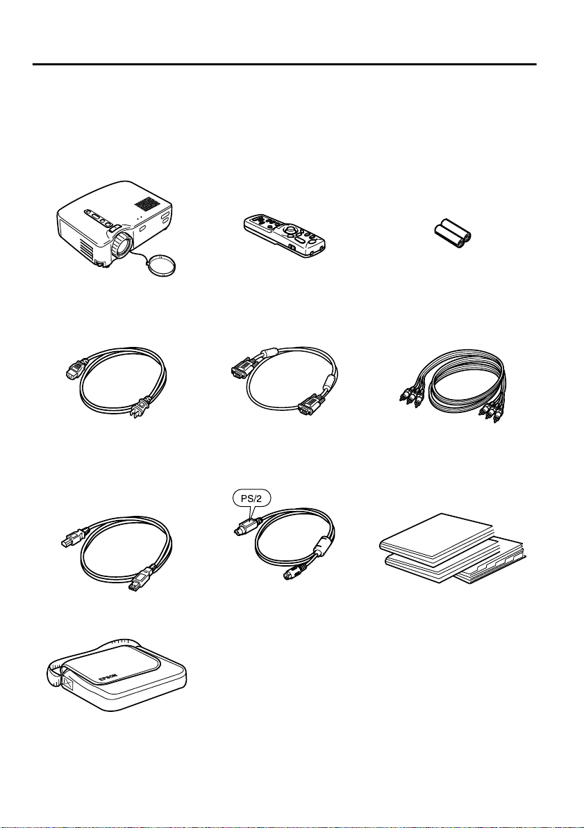
Checking Accessories
When unpacking the projector and accessories from their box, check that the
following items are included.
If any of the components are missing or incorrect, please contact the place of purchase.
•Projector
• Lens cover with cord
• Power cord (9,8 ft (3 m)) • Computer cable
• USB mouse cable (6 ft
(1,8 m))
• Remote control • Two manganese dry cells
(6 ft (1,8 m))
• PS/2 mouse cable (6 ft
(1,8 m))
for the remote control
• Audio/Video (A/V) cable
(red/white/yellow)
(6ft (1,8 m))
• Safety Instructions/WorldWide Warranty Terms
• Instruction Manual
(this manual)
• Quick Reference Guide
• Soft case
Page 3

In This Manual
Getting Started
Name and function of each part and of the remote control operation
Setup
Special notes on setup, setup instructions, and screen size and projection
distance details
Projecting Images
Connecting with different devices and projecting and adjusting images
What You Can Do
Functions to get the most out of your projector
Menu Functions (Remote Control Only)
Basic menu functions and settings
Troubleshooting
Troubleshooting projection failure, bad projection, and other problems
Maintenance
Performing lamp replacement and other routine maintenance and care
General Notes
Optional parts, glossary, index, specifications
1
Page 4

Contents
In This Manual.................................................................................. 1
Features............................................................................................ 4
About The Manuals and Notations Used.......................................... 6
Getting Started
Part Names and Functions............................................................... 8
Remote Control............................................................................... 11
Setup
Special Notes on Setup .................................................................. 14
Setup Instru ct io n s ... .. ............... ....................................................... 1 5
Screen Size and Projection Distance Details ................................. 16
Projecting Images
Connecting to a Computer.............................................................. 18
Connecting to an A/V Device.......................................................... 21
Providing Sound Through an External Audio Device...................... 23
Projecting Images................................ .......................................... . 24
Adjusting Images ............................................................................ 28
Ending After the Projection............................................................. 31
What You Can Do
Using the Wireless Mouse.............................................................. 34
Enlarging an Image......................................................................... 36
Adjusting Im a g e Size.......................................... ............................ 3 7
Adding Image Effects................ .................... .................... .............. 38
Freezing and D e le ti n g Im a g es.............. ................ .......................... 39
Displaying H e lp Screens. ............................. ............................. ...... 40
2
Page 5

Menu Functions (Remote Control Only)
Learning Basic Operations......................................................... .... 42
Video Menu...................................... .. ............................. .. ............. 43
Audio Menu.................................................................................... 45
Effect Menu.................................................................................... 46
Setting Men u.................................................................................. 47
Advanced Menu............................................................................. 49
About Menu.................................................................................... 50
Reset All Menu............................................................................... 51
Troubleshooting
Possible Fa ilu res . .................................................................... ....... 54
When Indicators Do Not Help......................... .................... ............ 57
Maintenance
Projector Cleaning, Lens Replacement,
Air Inlet Cleaning.......................................................................... 64
Lamp Repla c e m e n t........................................................................ 66
General Notes
Optional Accessories..................................................................... 70
Glossary......................................................................................... 71
Specifications................................................................................. 73
External Dim e n s io n s ............................ .......................................... 75
Index...................................................................... ........................ 76
3
Page 6
Features
Compact and Lightweight
The compact, lightweight design of your projector (6.6 liters and roughly 3.1
kilograms (6.83 pounds) ) allows easy carrying.
Clear, Sharp Images
Though compact, your projector provides clear, sharp presentations even in
well-illumi nated areas.
Global Video Signal Compatibility
Your unit projects virtually all of the video signal formats used world-wide,
including NTSC, NTSC4.43, PAL, M-PAL, N-PAL, PAL60, and SECAM.
Improved Video Image Clarity
Projection of distinct video images from composite video and S-video input is
possible.
"Keystone" Correction Function (See pages 29 and 47)
This built-in fun ction all ows easy cor rection o f trapezo idal dist ortion c aused by
projection angle.
Wireless Mouse Remote Control for Computer Mouse Operations (See
page 34)
The remote control allows wireless operation of various projector functions,
including cursor/stamp, horizontal bar display, and image enlargement and
reduction.
Presentation Effects Function (Remote control Effect button, See page 38)
Use of the remote control Effect button creates effective presentations.
Cursor/Stamp
Horizontal bar
4
Page 7
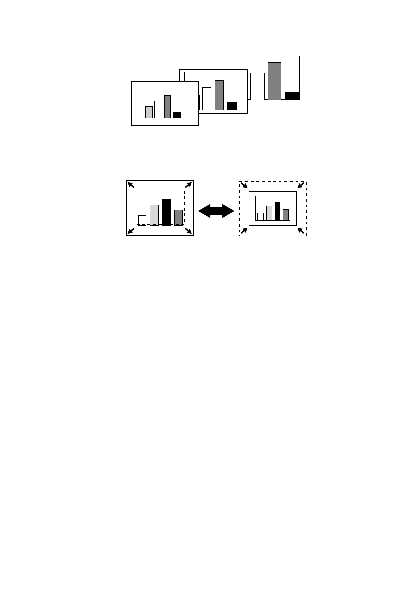
E-Zoom Function (Remote control E-Zoom button, See page 36)
Enlarges an image (from standard to 4x size vertically and horizontally).
Automatic image sizing with Wide/Tele button (See page 37)
Allows image enlargeme nt and reduction.
Enlargement Reduction
5
Page 8

About The Manuals and Notations Used
Types of Ma nu al
The documentation for your EPSON projector is divided into the following
three manuals. The manuals cover the following topics.
• Safety Instructions/World-Wide Warranty Terms
This manual contains information on using the projector safely, and also
includes World-Wide Warranty Terms and a Troubleshooting check sheet.
Be sure to read this manual thoroughly before using the projector.
• Instruction Manual (this manual)
This Instruction Manual contains information on installing the projector,
basic operation, us ing the pr oject or menus, tr oubles hooti ng and maint enance.
• Quick Reference Guide
Contains a n overview of the most commonly-used projector functions for
easy reference. You should keep this Quick Reference Guide near the
projector a t all times and refer to it before starting presentations and while
using the projector in order to check details of operation.
General information
Warning: Indicates procedures which may result in death or serious injury if
sufficient care is not taken.
Caution: Indicates procedures which may result in damage or injury if sufficient
care is not taken.
Tip: Indicates additional information and points which may be useful to know
regarding a topic.
*
Indicates that an explanation of the underlined word or words in front of
this symbol appears in the Glossary of Terms.
Refer to the Glossary in the General Notes. (See page 71)
Meaning of "unit" and "this product"
When "unit" or "this product" appears in the text of this Instruction Manual,
they may refer to items which are access ories or opti onal equipme nt in addit ion
to the main projector unit itself.
6
Page 9

Getting Started
Part Names and Functions........................................8
Remote Control.......................................................11
7
Page 10
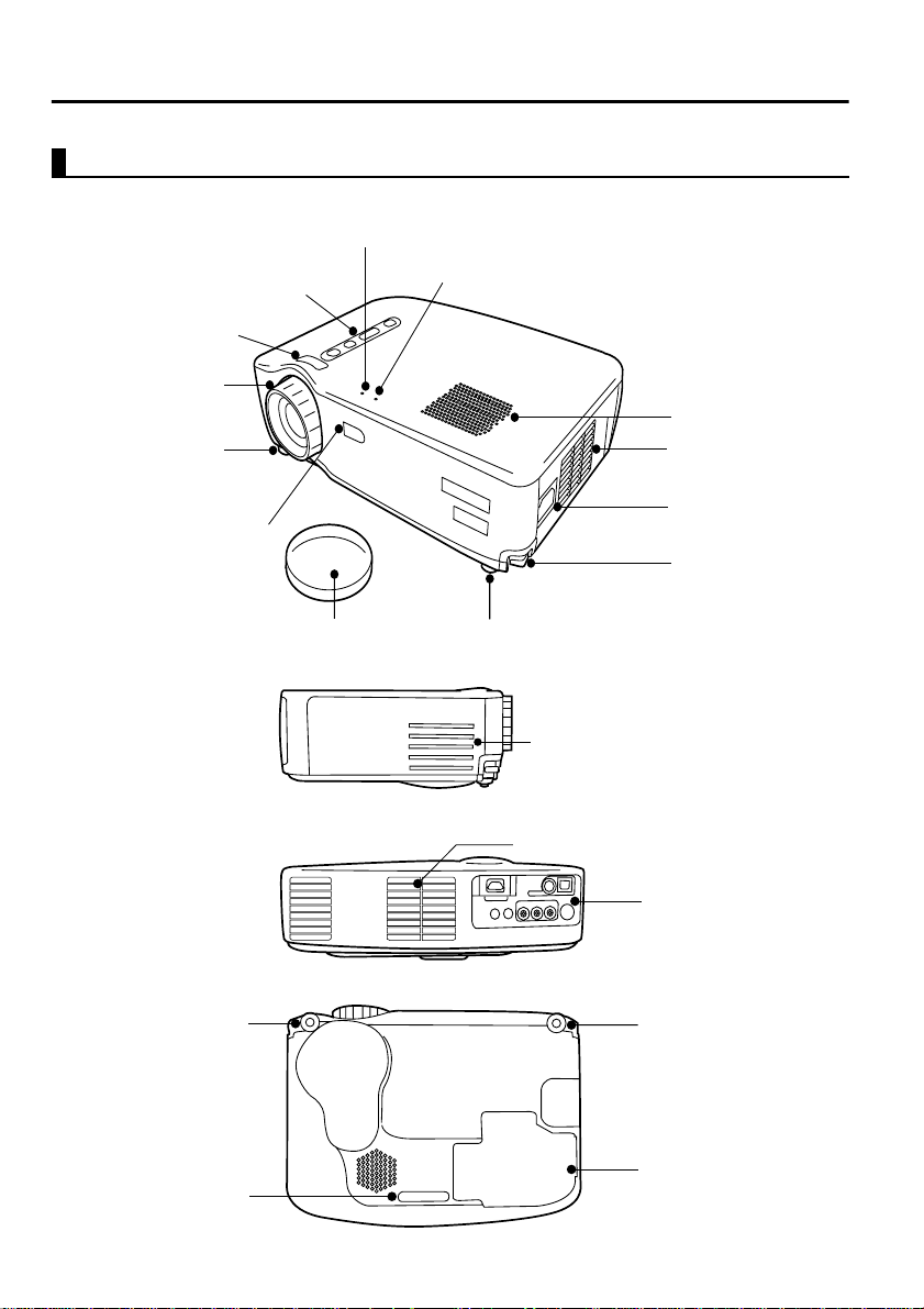
Part Names and Functions
Projector Unit
[Front]
Operation Display Indicator
Control panel
Wide/Tele Button
Focus ring
Front adjustable foot
Remote control receiver
Problem/Alarm Display Indicator
Speaker
Air exhaust vent
Power inlet
Foot adjust lever
[Side]
[Rear]
[Bottom]
Front adjustable foot
Rear adjustable foot
8
Lens cover
Front adjustable foot
Air inlet
Air inlet
Input/Output ports
Front adjustable foot
Lamp Cover
Page 11
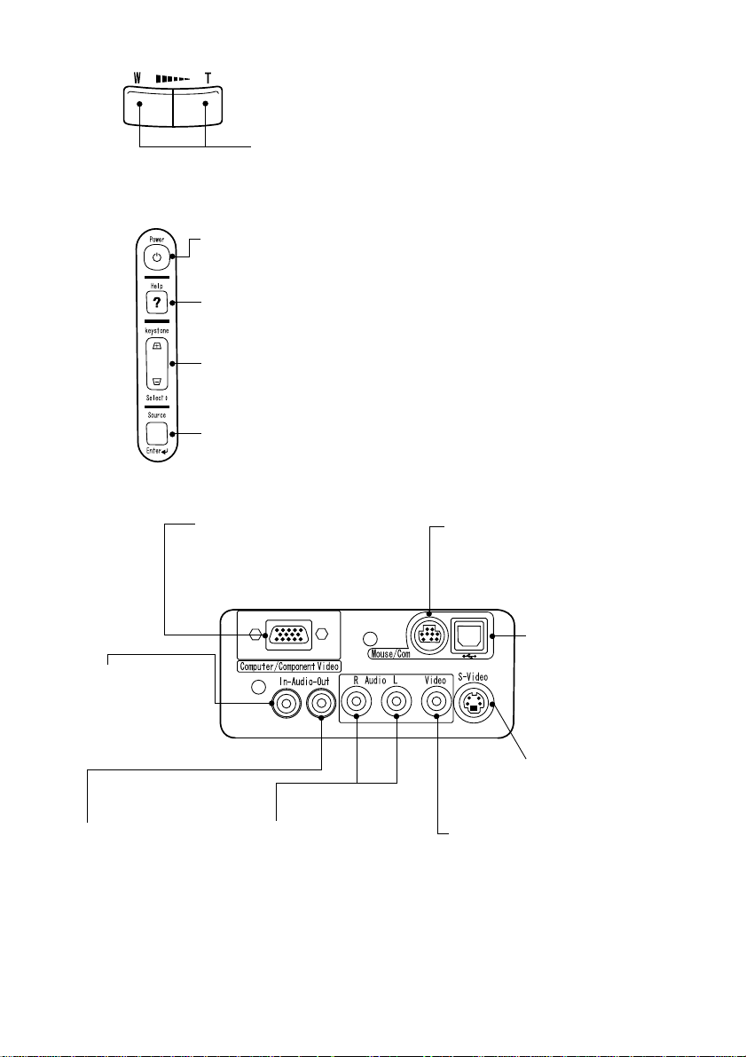
[Wide/Tele Button (See page 37)]
Press the T side (Tele) of the button to reduce the image size.
Press the W side (Wide) of the button to enlarge the image size.
[Control Panel]
Power Button (See pages 25, 31)
Switches power on and off.
*Press twice to turn the power off.
Help Button (See page 40)
Displays help screen.
Keystone (Select) Button (See pages 29, 40)
Adjust when screen is distorted trapezoidally.
When the help menu is displayed, functions as a "Select" button for menu items.
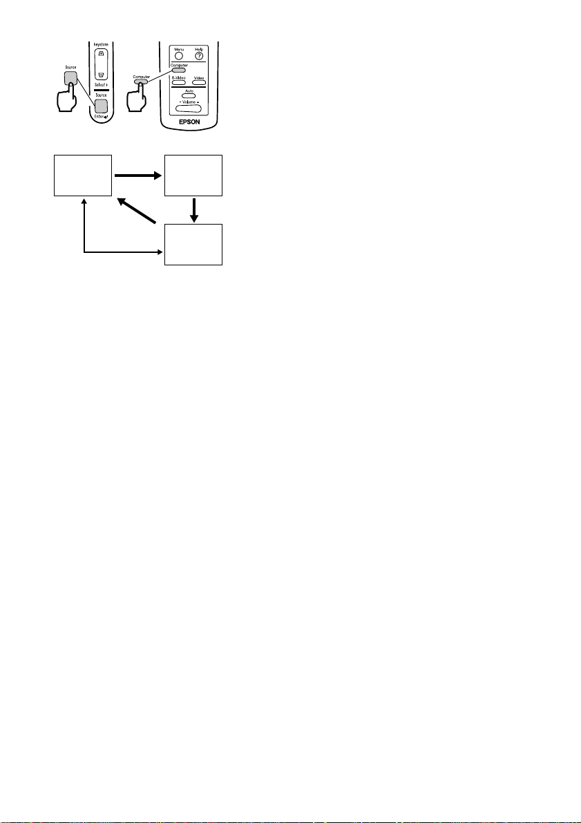
Source (Enter) Button (See page 26, 40)
Toggles the video source between Computer, S-Video, and Composite video.
When the help menu is displayed, functions as a "Enter" button.
[Input/Output Ports]
Computer/Component Video
port (See page 20)
For video signal input from
computer or component video.
Mouse/Com port (See page 35)
Used when using the remote control as
a wireless mouse.
Audio In port (See
page 20)
For input of audio
signal from
computer.
Audio Out port
(See page 23)
For output of audio signal
from projector.
Audio ports
(See page 21)
For input of audio signal
from A/V device.
USB Mouse port
(See page 35)
Used when using the
remote control as a
wireless mouse.
S-Video port
(See page 21)
For input of S-video
signal from A/V device.
Composite Video port
(See page 21)
For input of Composite Video signal
from A/V device.
9
Page 12
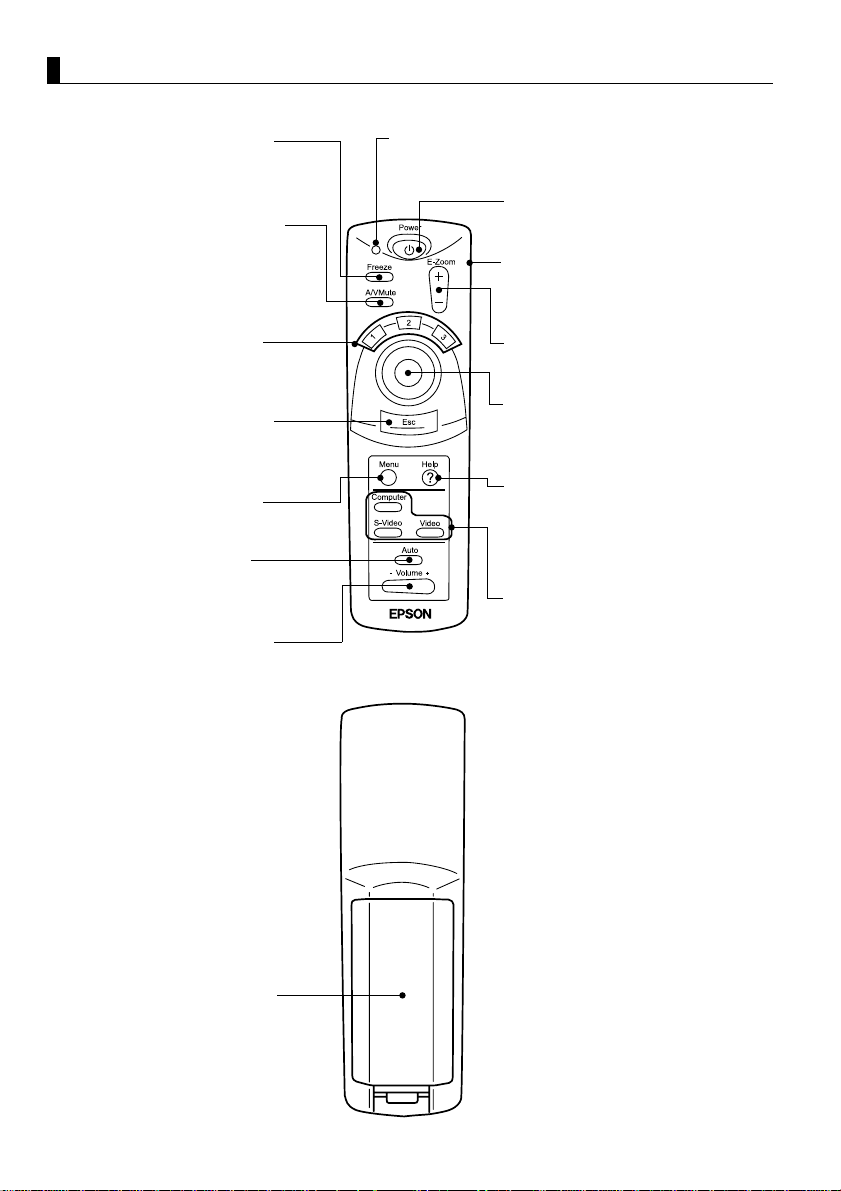
Remote Control
[Front]
Freeze Button (See page 39)
Temporarily stops a moving picture.
To release the freeze, press the
button again.
A/V Mute Button (See page 39 )
Temporarily eliminates picture and
sound.
To release muting, press the button
again or adjust the volume.
Indicator
Lights during signal output from remote control.
Power Button (See page 25, 31)
Switches projector power on and off.
*Press twice to turn the power off.
R/C switch (See pages 25, 32)
Switches remote control power on
and off.
Effect Button (See page 38)
Executes an assigned effect
function.
Esc Button (See page 34, 42)
To terminate an activated function,
or right-click function when using as
a wireless mouse.
Menu Button (See page 42)
Displays or cancels menus.
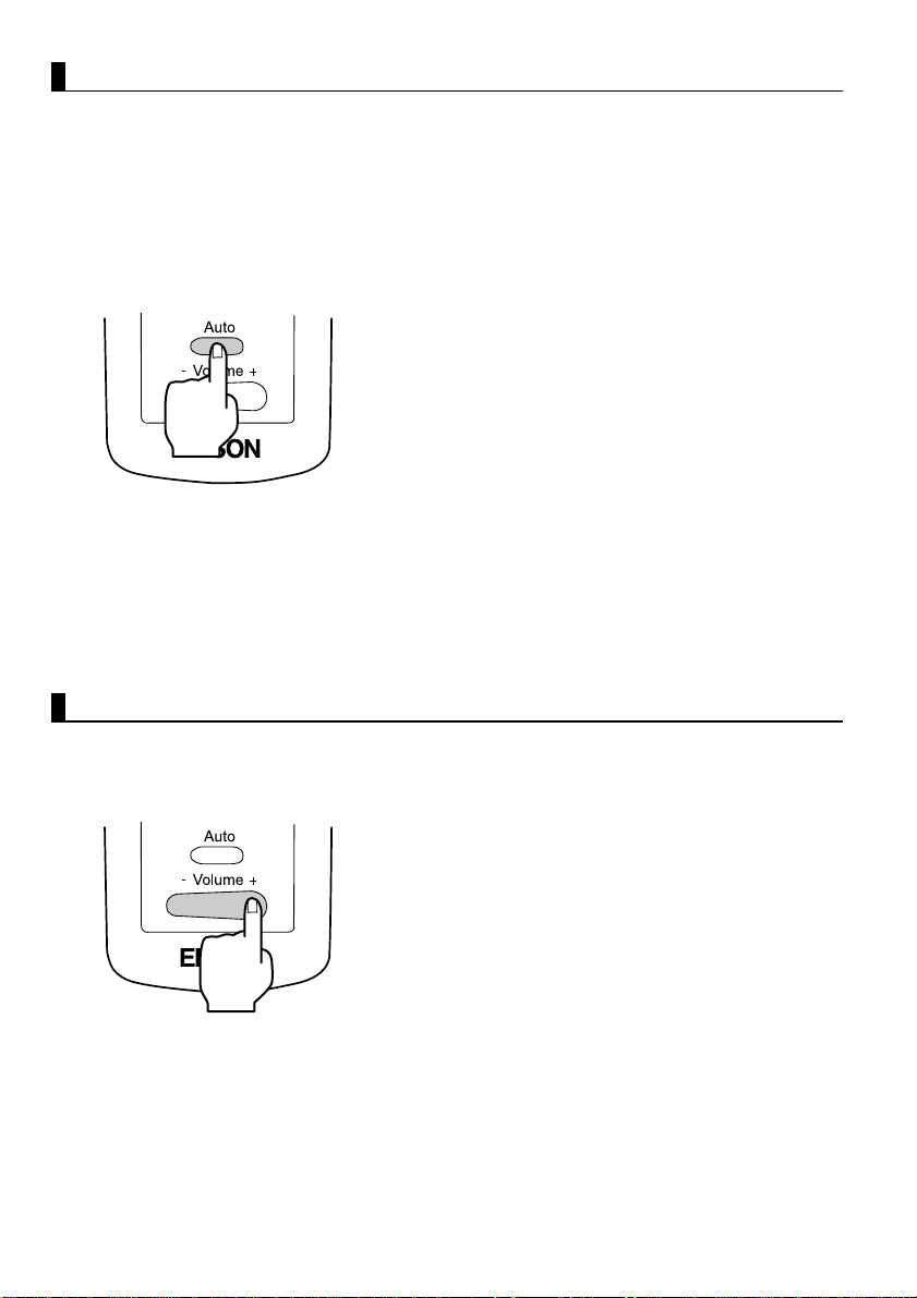
Auto Button (See page 30)
Optimizes computer video.
Volume Button (See page 30)
Adjusts volume.
[Back]
E-Zoom Button (See page 36)
Executes the E-Zoom function.
Enter Button
Used for scrolling, menu item
selection, and as the left mouse
button.
Help Button (See page 40)
Provides topic-specific explanation
for addressing problems.
Use this button when problems
occur.
Computer, S-Video, Video Button
(See page 26)
Switches to the selected video
source.
10
Battery Cover
Page 13
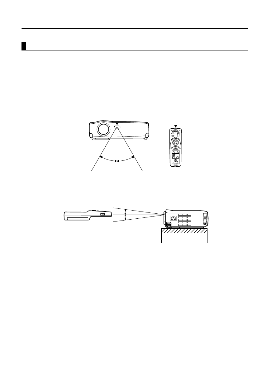
Remote Control
Operating Range
The remote control may not operate beyond certain distances and angles from
the receiver on the projector. Observe the following conditions during use.
[Operating Distance : Approximately 393.70inches (10m) ]
[Operating Area:]
Horizontally
Remote control receiver
Approximately 30º Approximately 30º
Remote control
transmitter
Vertically
Approximately 15º
Tip:
• The remote control R/C switch must be switched to "On" to use the remote control.
• Point the remote control towards the remote control receiver on the projector unit.
• Certain screens may shorten the operating distance (approximately 393.70inches
(10m) ) of the remote control when the control is pointed towards the screen to reflect
its signal during use.
• Situate the remote control receiver out of direct sunlight, fluorescent light, and
similar li ght sources .
These may cause the remote control to malfunction.
• If the remote control malfunctions or stops operating, the batteries may need
changing.
Replace the batteries with a fresh set.
11
Page 14
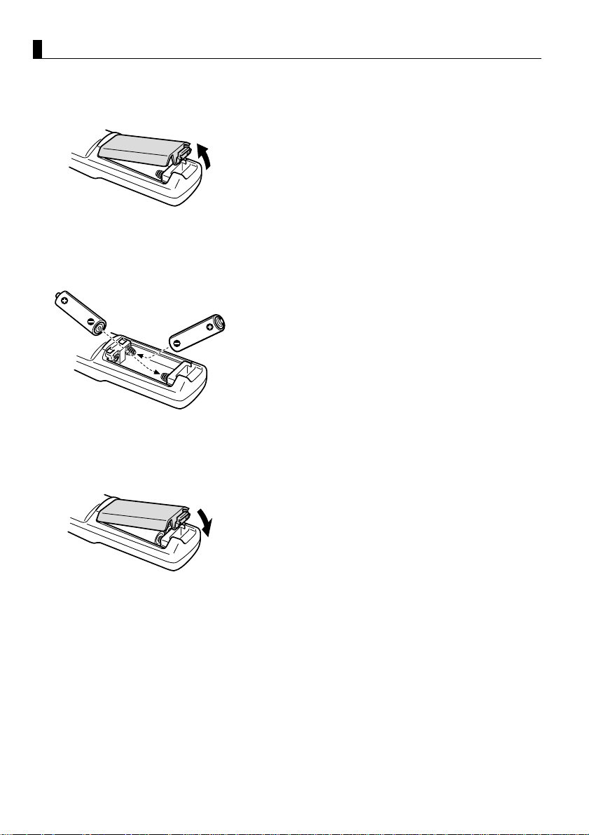
Inserting Batteries in the Remote Control
This section describes how to insert batteries in your remote control.
1.
Remove the battery cover.
Slide the catch of the battery cover in the
direction shown by the arrow.
Tip:
Be sure to use fresh batteries of the same type as
the old.
2.
Insert batteries.
Be sure to match the polarity to that
indicated on the remote control.
Tip:
•Battery type
Two manganese dry cells R6 (AA)
• Use o f 30 minutes per day will requir e a
change of batteries approximately every 3
months.
12
3.
Replace the battery cover.
Press the battery cover into the remote
control until it clicks firmly into place.
Page 15

Setup
Special Notes on Setup...........................................14
Setup Instructions...................................................15
Screen Size a nd P roj ect io n D ista nce De tai ls................ 16
13
Page 16
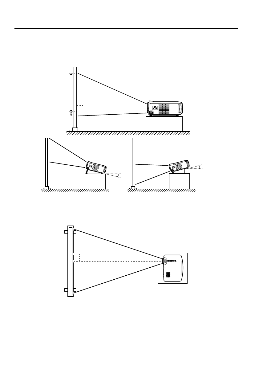
Special Notes on Setup
The best picture is obtained when the projector and screen are set up facing
each other directly, as shown below. Set your projector and screen up this way.
[View from right or left]
9
90º
1
Upward approximately 15º
15º
Downward approximately 15º
15º
Keystone correction all o ws cor re ct ion of tr apezoidal distortion ( See page s 29,
47).
[View from above or below]
90º
Caution:
• Do not block the air exhaust vent on the side of the projector or the air inlets on the
right side and rear of the projector.
• Do not place the unit in direct contact with air conditioner, heater, or other
ventilation currents.
• When setting up the projector near walls, allow at least 7.87inches (20cm) from all
walls.
14
Page 17
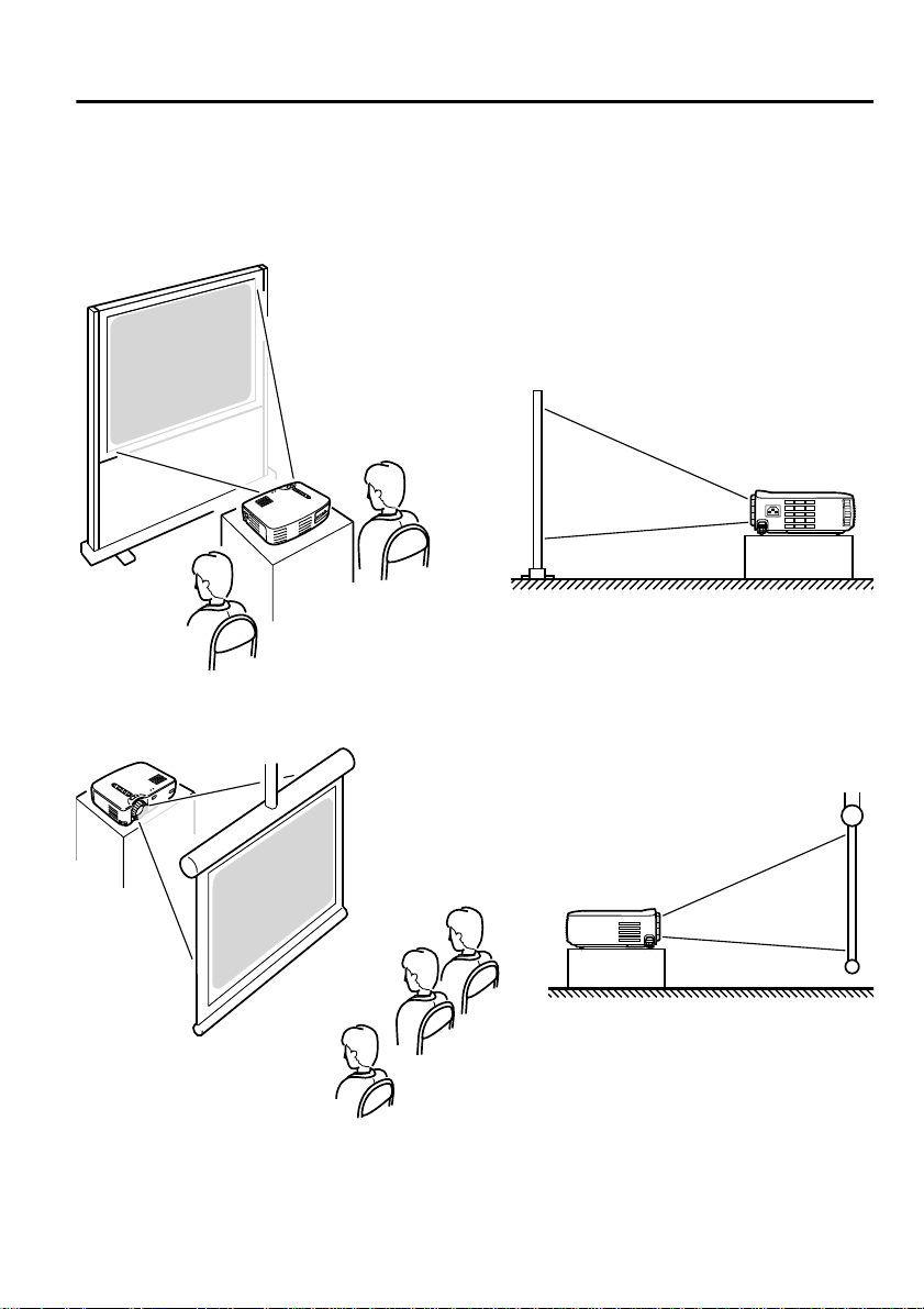
Setup Instructions
Your projector allows projection in the following two ways. Set up the
projector as your location requires.
[Viewing from the front]
[Projection on a semi-transparent screen and viewing from the rear]
15
Page 18
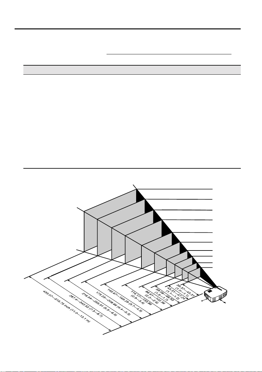
Screen Size and Projection Distanc e Details
Select a distance from lens to screen that provides your desired screen size.
The recommended distance is 39.37inches (1.0 m)—515.75inches (13.1 m)
Refer to the fo llowing table for setup.
Screen size (inch (cm) ) Approximate projection distance* (inch (m) )
300” (240.16x181.1 (610x460)) 433.07—515.75 (11.0—13.1)
200” (161.42x118.11 (410x300)) 287.4—342.52 (7.3—8.7)
150” (120.08x89.76 (305x228)) 216.54—255.91 (5.5—6.5)
120” (96.06x72.05 (244x183)) 173.23—208.66 (4.4—5.3)
100” (78.74x59.06 (200x150)) 145.67—169.29 (3.7—4.3)
80” (62.99x47.24 (160x120)) 114.17—133.86 (2.9—3.4)
60” (47.24x35.43 (120x90)) 86.61—102.36 (2.2—2.6)
40” (31.89x24.02 (81x61)) 59.06—66.93 (1.5—1.7)
30” (24.02x18.11 (61x46)) 43.31—47.24 (1.1—1.2)
28” (22.44x16.93 (57x43)) 39.37—43.31 (1.0—1.1)
* Use the "approximate projection distance" as a guide to setup. Projection
conditions and other factors can affect results.
300"
200"
610x460 (cm)
410x300
305x228
244x183
200x150
160x120
120x90
81x61
61x46
57x43
150"
120"
100"
80"
60"
40"
30"
28"
.
Tip:
A keystone correction will reduce screen size.
16
20(cm
* When installing against a wall, leave a
space of about 7.87 inches (20 cm) between
the projector and the wall.
20(cm)
)
*
*
Page 19

Projecting Images
Connecting to a Computer......................................18
Connecting to an A/V Device.................................21
Providing Sound Through an External
Audio Device........................................................23
Projecting Images ...................................................24
Adjusting Images....................................................28
Ending After the Projection....................................31
17
Page 20

Connecting to a Computer
Computers which can be connected
Some computer models may not allow connection, and others may allow
connection but not projection.
Make sure that the specifications of the computer you are using for connection
meet the following two requirements.
[The computer must have a video signal output port]
Make sure that the computer has a port that outputs a video signal.
A port that outputs a video signal is called an "RGB port", "monitor port ", or
"video port" or the like.
Consult the section de scribing "connecti on to an external mo nitor" or th e like
in the instruction manual for the computer that you are using, and make sure
that the computer has a video signal output port.
Computers w ith an integrated monitor and other components as well as
laptop computers may require separate purchase of an external output port.
In other cases, an external output port cannot be attached.
[The resolution and fre quency of the compute r must be withi n the range of
specifications shown on the following page]
The resolution and frequency of the video signal output by your computer
must be compatible with your projector in order to allow projection (some
computers allow partial projection, but clear projection cannot be obtained).
Check the resolution and frequency of the video signal in the instruction
manual of the computer you are using for projection.
18
Page 21
Compatible Mode Chart for Connectable Computers
If the resolution and frequency of the video signals which are output from the
computer do not corres pond to a ny of t he valu es in t he tabl e belo w, tho se vide o
signals cannot be projected. (In some cases it may be possible to project such
signals, but they will not produce clear images.)
Check the instructi on manual for the computer fo r de tails on the resoluti on a nd
frequency of the video signals.
Furthermore, some computers may let you change the output resolution. If this
is the case, change the resolution to a value in the table below.
Frequency used for
Signal (Resolution)
(dots)
PC (RGB)
compatible modes
PC (YUV)
compatible modes
Video
compatible modes
Signal
640 x 350 VGAEGA 60 1024 x 560 800 x 437
640 x 400 VGACGA 60 1024 x 640 800 x 500
720 x 400 VGA
720 x 350 VGA Text 70 1024 x 497 800 x 388
640 x 480 VESA 60/72/75/85 1024 x 768 800 x 600
800 x 600 SVGA
1024 x 768 XGA
1152 x 864 SXGA
1280 x 960 SXGA2 60/75/85 1024 x 768 -
1280 x 1024 SXGA3 43i/60/75/85 960 x 768 -
640 x 480 MAC13 66 1024 x 768 800 x 600
832 x 624 MAC16 75 1024 x 768 800 x 600
1024 x 768 MAC19 60/75 1024 x 768 800 x 600
1152 x 870 MAC21 75 1024 x 768 800 x 600
- HDTV525I 50/60 1024 x 768 800 x 600
- HDTV525P 50/60 1024 x 768 800 x 600
1280 x 720 HDTV750P 50/60 1024 x 576 800 x 450
1920 x 1080 HDTV1125I 50/60 1024 x 576 800 x 450
- NTSC 60 1024 x 768 800 x 600
- PAL 50 1024 x 768 800 x 600
- SECAM 50 1024 x 768 800 x 600
* Text 70 1024 x 568 800 x 444
* 43i/60/70/75/85 1024 x 768 800 x 600
*1 70/75/85 1024 x 768 -
Refresh rate
(Hz)
* 56/60/72/75/85 1024 x 768 800 x 600
resized displays
(when resizing is on)
(dots)
EMP-71 EMP-51
19
Page 22
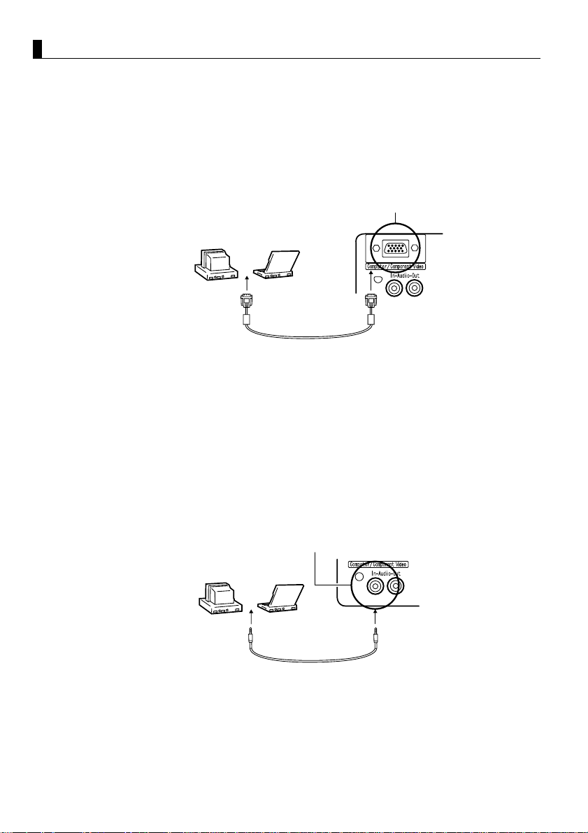
Connecting to a Computer
Tip:
• Before connecting, switch off power to the projector and computer.
• Check that cable and port interfaces match each other.
[Projecting Computer Video]
You can make presentations on a large screen by projecting computer video
from your projector.
Computer / Component Video port
Computer Monitor port
(Video port)
* If your computer port style is not a mini D-Sub 15-pin interface, use a connection
adapter that provides this interface.
When connecting to a Macintosh, you may need to use the optional Mac adapter.
Tip:
• When connected do not bind the power cord and the computer cable together.
• Some computer models may require a connection adapter during connection. Consult
your computer instruction manual or the computer vendor.
Computer cable
(accessory)
[Outputting Computer Audio From Your Projector]
You can output computer audio from the built-in speaker in your projector.
Your projector allows output at a maximum 1W.
Audio In port
Computer Audio
Output port
Audio cable
(sold separately)
Tip:
• When computer video has been selected or when audio input is specified on the
computer by menu, your projector outputs an audio signal from the computer.
• Purchase an audio cable that matches the port style of your computer's output port
and the projector's Audio In port (stereo mini jack).
20
Page 23
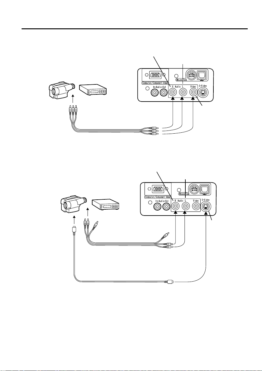
Connecting to an A/V Device
[Inputting a Composite Video Signal]
Audio (R) port (Red)
Audio (L) port (White)
To Video port (Yellow)
To Audio (L) port (White)
To Audio (R) port (Red)
A/V cable (accessory)
[Inputting an S-Video Signal]
Audio (R) port (Red)
Video port
(Yellow)
Audio (L) port (White)
To S-Video
port
A/V cable
(accessory)
To Audio (L) port (White)
To Audio (R) port (Red)
S-Video cable (sold separately)
S-Video
port
21
Page 24
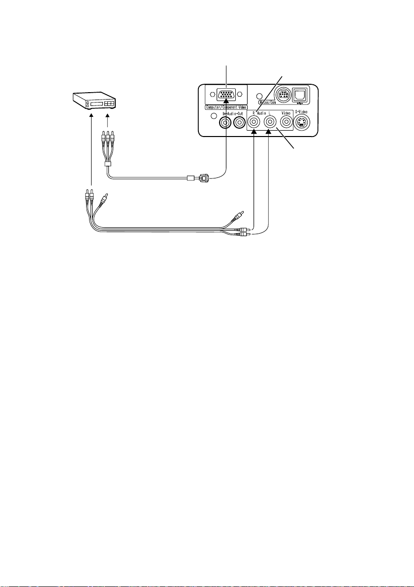
[Inputting a Component Video Image Signal]
If using a component video cable
Computer/Component Video port
Audio (R) port (Red)
DVD player, etc.
To Y port (Green)
To Pb or Cb port (Blue)
To Pr or Cr port (Red)
Component video cable (optional part)
A/V cable (accessory)
To Audio (L) port (White)
To Audio (R) port (Red)
Tip:
• When projecting a component video image, select "YCbCr" or "YPbPr" in the Video
> Input Signal menu.
Select "YCbCr" if using a DVD player, and select "YPbPr" if using a HDTV video
source.
• To change the aspect ratio of the projected image between 4:3 and 16:9, select Video
> Aspect Ratio menu.
Audio (L) port
(White)
22
Page 25
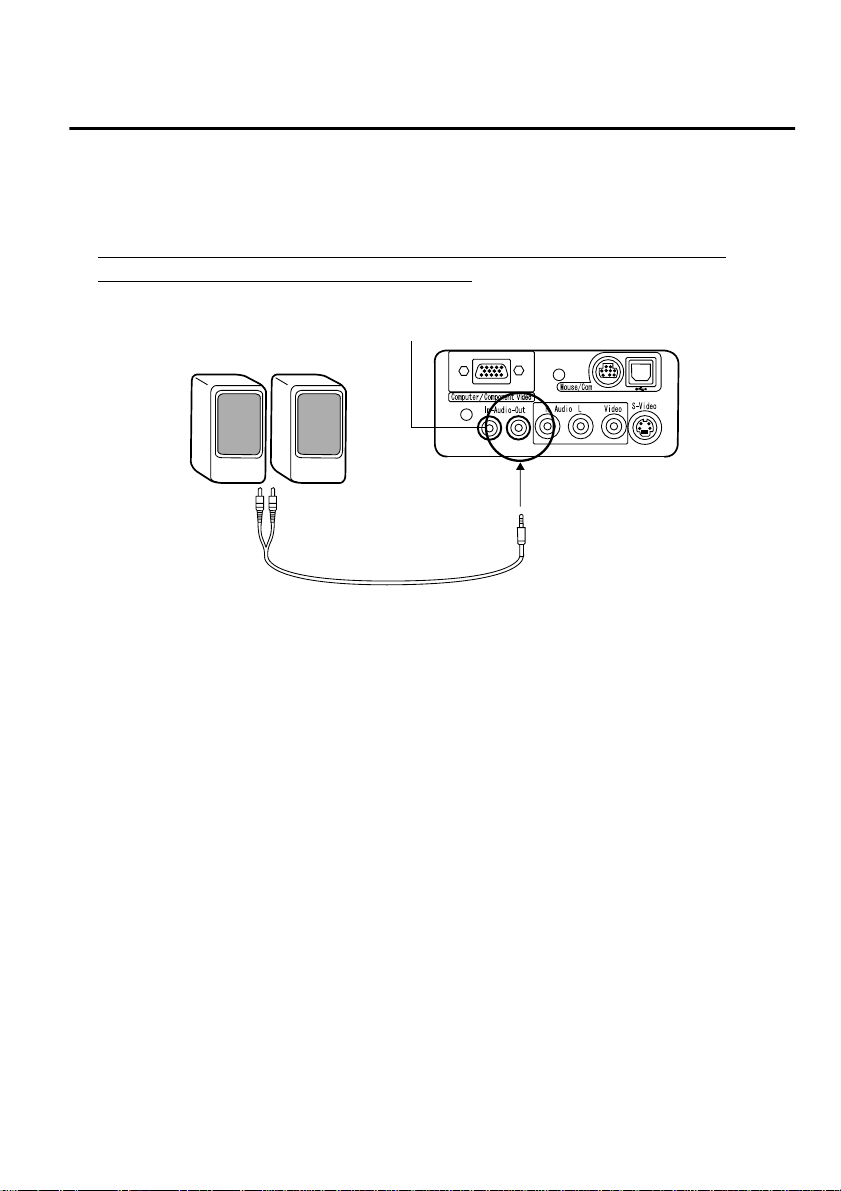
Providing Sound Through an External Audio Device
Connecting the Audio Out por t of your p rojector to a PA syst em, active speaker
system, or other speakers with built-in amplifiers provides powerful, pleasing
sound.
Use a separately sold audio connection cable (pin ring) connecting to a
0.14inches (3.5mm) stereo mini-jack plug.
Audio Out port (Stereo mini jack)
External Audio Device
Audio cable
(sold separately)
Tip:
• When a cable is connected at the
the built-in speaker to external sound output.
• Though the projector outputs audio for projected video images, in the case of A/V
devices, the audio output corresponds to the audio devices connected to the Audio
port
s.
• Before purchasing an audio connection cable, thoroughly check the connection
interface style of the external audio devices you are connecting.
Audio Out port
the sound output will be s witched from
23
Page 26

Projecting Images
Here we begin projecting images from an A/V device.
Preparation
Warning:
• Never look into the lens when the projector is switched on. The intense light can
damage your vision.
• Use only the power cord supplied. Use of other cables may cause fire or electric
shock.
Caution:
Do not attempt projection with the lens cover in place. Heat may deform the lens
cover.
1.
Check th at the projec tor and computer or A/
V device are connected.
2.
Remove the lens cover.
24
Power inlet
3.
Attach the power cord (accessory) to the
projector.
Align the power cord connector with the
power inlet on the projector and insert the
connector firmly and completely into the
inlet.
4.
Insert the plug end of the power cord in an
outlet. The operation display indicator will
light with an orange color.
Tip:
Buttons cannot be operated while the operation
display indicator is flashing orang e .
Page 27

Projection
When preparations are complete, you are ready for projection.
1.
To use the remote contr ol, turn the remote
control R/C switch to "On".
2. Press the Power button to switch power on.
The operation display indicator begins to
flash green, and projection begins.
Projector Remote control
After approximately 30 seconds, the
operation display indicator changes from
flashing green to steady green.
"No-Signal" is displayed.
Depending on your settings,
there may be no display.
(See page 47)
The operation display indicator
lights green.
25
Page 28
Projector Remote control
Computer
When no S-Video
input
S-Video
Video
3.
Press the Source button on the projector or
the Computer, S-Video or Video button on
the remote control to select the video source
you wish to project.
Each time the Source button on the projector
is pressed, the video source cycles between
Computer, S-Video and Video.
If there is no input at the S-Video port, the
Source button switches the video source
from Computer to Video.
Tip:
If projecting a component video picture, change
the setting to Computer.
4.
Switch on power to the computer or A/V
device to begin projection.
The "No-Signal" display disappears, and a
video signal from the computer or A/V
device is projected.
Tip:
• If the "No-Signal" display remains, check the
connections again.
• If the same static image is projected for some
time, the video projection may contain an
afterimage.
26
Page 29

[Settings for laptop and integrated LCD computers (when connected)]
When a laptop or integrated LCD computer is connected to the projector,
some computers require key commands or settings to change the output
destination of a video signal.
Keep "Fn" depressed while pressing "F0" to change the setting.
For details, consult the instruction manual of the computer you are using.
Manufacturer Output Switching Example
NEC
Panasonic
Toshiba
IBM
SONY
Fujitsu
Macintosh After restarting, the monitoring and sound on the
control panel are set to mirror the computer.
Tip:
Some computers may not be able to have images displayed on the computer screen at
the same time as they are being projected. In such cases, use only external output.
"Fn"+"F3"
"Fn"+"F3"
"Fn"+"F5"
"Fn"+"F7"
"Fn"+"F7"
"Fn"+"
F10
"
27
Page 30

Adjusting Images
This section describes how to obtain the best video performance.
See "Setup" (page 13) for details on setting-up position and projection size.
Adjusting the Image Projection Angle
Adjust the projection angle of the projector.
Adjust the projector to face the screen as directly as possible.
1.
Lift the projector to your desired angle of
projection.
Foot adjust levers
Raise
Lower
2.
Use your fingers to pull up the foot adjust
levers.
Front adjustable feet emerge.
3.
Release the foot adjust levers.
4.
Make fine adjustment s to the height.
Turn the lower portion of the front
adjustable feet to make fine adjustme nts to
height.
Tip:
Setting back the front adjustable feet (See page
32)
28
Page 31

Adjusting the Focus
This section describes how to adjust the video focus.
1.
Turn the focus ring on the projector to adjust
the focus.
Tip:
• Focus cannot be achieved if the lens is dirty or
covered with condensation. Wipe off any dirt
or condensation (See page 64).
• If adjustment does not succeed, make sure the
setup distance is between 39.37inches (1.0m)
and 515.75inches (13.1m).
Keystone Correction (Using Projector Button)
When the foot adjust levers are used to change the projection angle, the
keystone correction function can be used to correct trapezoidal distortion
upward or downward by roughly 15°.
1.
Press the Keystone button on the projector
to minimize the trapezo idal distortion.
Tip:
• A keystone correction reduces screen size.
• The keystone correction is stored in memory.
You will need to readjust the image if the
projector is moved to a different location or t he
projection angle is changed.
• If a keystone correction makes the image
noticeably uneven, reduce the video sharpness
with the menu commands Video > Sharpness
(See page 44).
29
Page 32
Adjusting Images (Remote Control Only)
[Optimizing Computer Video (Using the Auto button)]
This function applies automatically optimized adjustment values to a
computer input signal.
If the input is a video signal, this function does not operate.
Adjusted values set automatically are "Tracking", "Position (vertical and
horizontal)", and "Sync" .
Tip:
• This function cannot optimize the adjustment
for some signal types. In these c ases, use the
Video Menu commands to perform adjustment
(See page 43).
• When functions such as E-Zoom or A/V muti ng
are engaged, these functions being used will be
canceled before automatic adjustment is
carried out.
[Opening a Menu For Adjustment]
Press the Menu button and perform adjustment using the Video Menu.
For details, refer to "Menu Functions (Remote Control Only)" (See page 41).
Adjusting the Volume (Remote Control Only)
Press the Volume +, - button to adjust the volume to an easily au dible listening
level.
Tip:
Adjustment is not available if there is no audio
signal.
30
Page 33

Ending After the Projection
Ending
1.
Press the Power button. A "Power Off"
confirmation message is displayed.
2.
Press the Power button again.
The projector lamp goes out, the operation
display indicator flashes orange, and after
Projector Remote control
cool-down
switches to steady orange.
Tip:
If you do not wish to shut the power, press
another button.
Or, if no action is taken, the messa ge disapp ears
after 7 seconds.
* is complete, the indicator
Operation display indicator
lights orange.
3.
Check that the operation display indicator
lights orange.
Tip:
• The flashing orange operation display
indicator indicates that cool-down ( which takes
about 2 minutes) is in progress.
Buttons cannot be operated during cool-down.
• If the power cord plug is pulled out of the
outlet, the operation display indicator will go
out.
31
Page 34

4.
Pull the power cord plug out of the outlet.
Caution:
Do not pull the power co rd plug out of the outl et
while the operation display indicator is flashing
orange. This may cause a malfunction or
shorten the projector lamp life.
5.
Set the remote control R /C switch to Off.
Tip:
Unless the remote control R/C switch is switched
off, a small amount of current will be supplied to
the remote control and exhaust the batteries. If
the remote control will not be used for a long
period or you are moving the unit, set the remote
control R/C switch to Off.
Storage
When you are finished projecting, retract the front adjustable feet into the unit.
Foot adjust levers
1.
Support the projector unit with your hands,
pull upward on the foot adjust levers with
your fingers, and lower the unit slowly.
2.
Attach the lens cover.
32
Page 35

What You Can Do
Using the Wireless Mouse......................................34
Enlarging an Image.................................................36
Adjusting Image Size..............................................37
Adding Image Effects.............................................38
Freezing and Deleting Images................................39
Displaying Help Screens ........................................40
33
Page 36
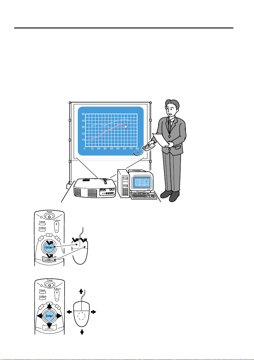
Using the Wireless Mouse
The remote control included allows you to control a computer's mouse
operations at a separate location.
The Enter button has the same ac tion as a left mous e butto n, and the Es c butto n
has the same action as a right mouse button.
Mouse operation by remote control allows you to make a presentation at the
screen without assistance.
Presenter
Unassisted presentation is possible
Remote Control Mouse
Remote Control
34
Tip:
• If mouse button functions are swapped on your
computer, the functions on the remote control
also change as follows.
Esc Button: Left mouse button
Enter Button: Right mouse button
• This function cannot be used while an Effect
Function, E-Zoom function, menu function, or
Help function is in use.
Mouse
Page 37

Making a Connection
Before making a connection, switch off power to the projector and computer.
Caution:
• Connecting a non-USB mouse cable with the power on can cause malfunction or
failure.
• Use only the mouse cable supplied. Any other cable may cause failure.
Mouse/Com port and USB Mouse port
Mouse/USB port
Mouse cable
(accessory)
Computer Mouse Cable Connection Method
IBM PC/AT Compatible
(DOS/V Machine)
Computer for USB* Mouse USB Mouse Cable Connect the computer USB port
PS/2 Mouse Cable Connect the computer mouse
port and the projector Mouse/
Com port.
and the projector USB mouse
port.
When using a USB mouse, note the following.
• Windows
The only compatible models are those pre-installed with the standard USB
interface configuration in Windows2000/Me and Windows98.
If the computer is running a version of Windows 98/2000/Me that has been
upgraded from an earlier version of Windows, correct operation cannot be
guaranteed.
• Macintosh
Compatible with OS 8.6 – 9.1.
* The USB mouse port is only compat ible for a USB m ouse, it is no t
compatible with other USB devices.
35
Page 38

Enlarging an Image
The remote control included lets you enlarge portions of an image.
1.
Enlargement
Reduction
Magnification factor is displayed.
Press the E-Zoom butt on on the rem ote
control to enlarge or reduce the display on
screen.
(The Esc button releases this feature.)
Tip:
24-step partial enlargement and reduction by
factors of 1x-4x is ava ilable.
2.
Tilt the Enter button up, down, left or right
to scroll the projected image in that
direction.
36
Push up
Push rightPush left
Push down
Page 39
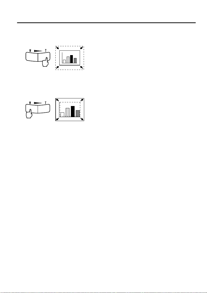
Adjusting Image Size
The Wide/Tele button on the projector allows you to adjust the size of images.
1.
When you press the T (Tele) side of the
button, the images are reduced.
2.
When you press the W (Wide) side of the
button, images are enlarged.
Tip:
• The enlargement/ reduction ratio for
adjustment with the Wide/Tele button is
0.8 – 1.0 in 32 steps.
• This function is active until th e Reset All menu
is executed (See page 51).
37
Page 40
Adding Image Effects
Using the Effect1 and Effect2 buttons, you can add effects to images during
presentation (to cancel this function, press the Esc button).
For effects settings, see "Effect Menu" (page 46).
Cursor/Stamp
This effect displays a cursor on the screen and freezes it at a desired location.
1.
Press the Effect1 button to display a cursor.
2.
Tilt the Enter button to move the curs or to a
desired position.
3.
Press the Enter button, and the cursor
position is displayed as a stamp.
Tip:
• Activate the horizontal bar to remove the
cursor/stamp display.
• To remove the stamp, press the Effect3 button.
Horizontal Bar
This effect displays a horizontal l ine on the s creen and al lows you to move i t up
or down by remote control.
1.
Press the Effect2 button to display a
horizontal bar.
2.
Tilt the Enter button up or down to move the
horizontal bar up or down.
Tip:
• To remove the horizontal bar, activate the
cursor/stamp.
38
Page 41
Freezing and Deleting Images
Freezing a Moving Image (Remote Control Only)
You can freeze a moving image (video or other image).
1.
Press the Freeze button on the remote
control.
(To release the freeze, press the Freeze
button again.)
Muting Images and Sound (Remote Control Only)
You can temporarily mute images and sound and project a black or blue image.
1.
Press the A/V Mute button on the remote
control.
(To cancel the muting featu re, press the A/V
Mute button or another button.)
Tip:
Using the Setting > A/V Mute menu, you can
change the color (black, blue) of the image
projected when audio and video have been
muted (See page 48).
39
Page 42

Displaying Help Screens
You can display topic-specific help on screen for solving problems. Use this
function when problems occur.
1.
Press the Help button to start the help
function.
(Press the Help button again to cancel this
function.)
Tip:
If you cannot solve your problem using the Help
Projector Remote control
Enter
Enter
Projector Remote control
function, consult the "Troubleshooting" section
in this manual (See page 53).
2.
Tilt the Select button on the projector up or
down to select a topic (on the remote
control, tilt the Enter button up or down).
40
Enter
Enter
Projector Remote control
3.
Press the Enter button to enter your
selection.
4.
Select a detailed topic as de scribed in steps 2
and 3 and follow the instructions displayed.
Page 43

Menu Functions
(Remote Control Only)
Learning Basic Operations .....................................42
Video Menu............................................................43
Audio Menu............................................................45
Effect Menu............................................................46
Setting Menu...........................................................47
Advanced Menu......................................................49
About Menu............................................................50
Reset All Menu.......................................................51
41
Page 44

Learning Basic Operations
This section presents the basic functions available in menus. The menu can be
controlled by the remote control.
For functions in each menu, access the guide available under each menu.
[Guide for explanation of symbols]
: Tilt the Enter button up or down. : Tilt the Enter button left or right.
: Press the Enter button. : Press the Esc button.
[Opening and Closing Menus]
Press the Menu button to display the top menu.
To close this menu, press the Menu button again.
To close this menu, press the Menu button. All the settings will be saved
when the menu is closed.
[Menu Selection]
Tilt the Enter button up or down to
Tilt the
Enter button
down.
Tilt the
Enter button
up.
move the pointer up or down.
[Moving in Hierarchy Structure Sub-menu selection]
Press the Enter button to move to the
sub-menus.
When pressing the Esc button, the
settings will be saved and the menu
returns to the top menu.
Press Enter Press Esc
Press the Menu button to clear the
menu display.
42
Page 45
Video Menu
Displaying Menus
Press the Menu button, use the Enter button to select "Video" from the top
menu displayed, and press the Enter button to move to a submenu.
Tip:
• When there is no video signal from a Computer / Component Video device, the
"Video" menu is not available for settings.
• When there is no video signal from a Vid eo device, o nly the "Mode" menu i s avail able
for settings.
Settings
Video menu elements to be set differ as follows when projecting computer/
component video versus video images.
Computer/Component Video Projection Video Projection
D-Sub15: Computer/Component video Video: Video image
Menu Content
Position Adjust video position vertically and
Tracking* Adjust when broad ve rtical s treaks appea r
Sync.
* Adjust when flickering or blurring occurs
horizontally.
* After position is adju sted, changes in the
video signal from a computer (such as
changes in output mo de or display color)
may change the adjusted value.
in image.
(Available for setting only when input
signal is RGB).
(available for setting only when input
signal is RGB).
* When tracking is wrong, adjustment of
sync will not correct flickering. Always
adjust tracking before adjusting sync.
: setting available : setting not available
Video Projection
D-Sub15 Video
43
Page 46

D-Sub15: Computer/Component video Video: Video image
Menu Content
Brightness Adjusts image brightness.
Contrast
Color Adjusts color depth.
Tint Adjusts tint.
Sharpness Adjusts image sharpness.
Gamma
Input Signal Select the input signal of the computer/
Auto Setup Optimizes computer input image.
Mode Select the video mode to use.
Aspect Ratio Select the aspect ratio
Reset Returns Video menu settings to factory sh ipping
* Adjusts difference in color brightness/darkness.
* Adjusts color of projected image.
+: Brightens image.
- : Darkens image.
+: Increas es difference in color br ightness/
darkness.
- : Decreases difference in color brightness/
darkness.
+: Deepens color.
- : Lightens color.
+: Strengthens red.
- : Strengthens green.
+: Strengthens sharpness and defines image.
- : Weakens sharpness and softens image.
* If keystone correction makes unevenness
distinctive, reduce the sharpness.
Dynamic: Increases contrast. (Used when
Normal : Sets normal contrast.
Natural : Weakens contrast to natural colors.
component video in use.
RGB: Computer images
YUV
(Can only be set when the input signal is RGB)
ON : Auto Setup active
OFF: Auto Setup not active
* Selection of Auto provides aut omatic vide o
signal identifica tion , but for PAL (60Hz) mode ,
set to Manual.
(Can only be set when projecting a component
video image (YCbCr*, YPbPr*).)
values.
* See page 52 for factory shipping values.
To reset all menus to factory shipping values,
use the "Reset All" menu.
projecting images c on t ai nin g t ext and
graphics)
(Used to give projected images a
more natural look)
*: Color difference* images
YCbCr
YPbPr
*: DVD images
*: HDTV images
*.
: setting available : setting not available
44
Video Projection
D-Sub15 Video
Page 47

Audio Menu
Displaying Menus
Press the Menu button, use the Enter button to select "Audio" from the top
menu displayed, and press the Enter button to move to a submenu.
Settings
Menu Content
Volume Adjusts the volume of sound output from the projector.
Tone Adjusts the tone of sound output from the projector.
Audio Input Select an audio input destination.
Reset Returns Audio menu settings to factory shippin g values.
+: Increases volume.
- : Decreases volume.
+: Increases treble.
- : Decreases treble.
(When the input signal is a component video signal, select Video.)
Auto : Audio input matching that of the displayed video is
selected.
(Example: When computer video is displayed, computer
audio input is selected).
Computer : Audio input from computer is selected.
Video : Audio input from an A/V device is selected.
* See page 52 for factory shipping values.
To reset all menus to factory shipping values, use the Reset All
menu.
45
Page 48

Effect Menu
Displaying Menus
Press the Menu button, use the Enter button to select "Effect" from the top
menu displayed, and press the Enter button to move to a submenu.
Settings
Menu Content
Cursor/Stamp Make detailed settings for the cursor/stamp function assigned to the
Horizontal Bar Make detailed settings for the horizontal bar function assigned to the
Cursor Speed Set the cursor speed.
Reset Returns Effect menu settings to their factory shipping values.
remote control Effect1 button.
Shape : Select the shape of the cursor/stamp.
Zoom Rate : Select the display zoom factor for the cursor/stamp.
remote control Effect2 button.
Color : Select the horizontal bar color.
Width : Select the width of the horizontal bar from 2-20 dots (in
2-dot steps).
L:Low
M : Medium
H:High
* See page 52 for factory shipping values.
To reset all menus to factory shipping values, use the Reset All
menu.
46
Page 49

Setting Menu
Displaying Menus
Press the Menu button, use the Enter button to select "Setting" from the top
menu displayed, and press the Enter button to move to a submenu.
Settings
Menu Content
Keystone If the screen is d is torte d i n t rapezoidal form, adjust it to normal display .
-: Broadens upper screen
* • You can also adjust the screen with the Keystone button on the
projector.
• A keystone correction reduces screen size.
• The keystone correction is stored in memory. You will need to
readjust the image if the projection angl e is chan ge d.
• If a keystone correction makes the image noticeably uneven,
reduce the video sharpness with the menu commands Video >
Sharpness.
No-signal/Msg Set the screen display when there is no video signal.
OFF : No message is displayed. (Screen displays black.)
Black : "No-signal" is displayed on a black background (when the
language is English).
Blue : "No-signal" is displayed on a blue background (when the
language is English).
Prompt Set whether the input source currently selected is displayed/not
displayed on the screen.
ON : After input source switching, the input source is displayed for
approximately 3 seconds.
+: Broadens lower screenNormal screen
OFF: The input source is not displayed.
47
Page 50

Menu Content
A/V Mute* Temporarily eliminates video during a presentation.
Sleep Mode After sleep mode is activ ated, the projector enters s tandby mode when
Reset Returns Setting menu settings to their factory shipping values.
When the A/V button is pressed again, the video display will continue.
Black : A black screen is displayed.
Blue : A blue screen is displayed.
no signal is inpu t from an ex ternal sourc e for a conti nuous perio d of 3 0
minutes.
ON : Sleep Mode active
OFF: Sleep Mode inactive
* See page 52 for factory shipping values.
To reset all menus to factory shipping values, use the Reset All
menu.
48
Page 51

Advanced Menu
Displaying Menus
Press the Menu button, use the Enter button to select "Advanced" from the top
menu displayed, and press the Enter button to move to a submenu.
Settings
Menu Content
Language Select the menu language.
Color Setting Use color temperature or RGB to create settings for the colors displayed
Rear Proj. This setting is used for projection from the rear of a screen.
Ceiling This setting is used for projection with the projector hanging from a
Reset Returns Advanced menu settings to their factory shipping values.
Select from Japanese, English, German, French, Italian, Spanish,
Portuguese, Chinese and Korean.
on screen.
Color Temp: Adjusts the color temperature* of the video.
Select "Color Temp" and press the Enter button to create
settings.
The setting unit is Kelvins (K).
+ : Increases color temperature (strengthens blue).
- : Decreases color temperature (strengthens red).
RGB: Adjusts red, green, and blue intensity.
Select "RGB" and press the Enter button to create settings.
+ : Strengthens color.
- : Weakens color.
ON : Inverts a projected image vertically.
OFF: Restores original .
ceiling.
ON : Inverts a projected image vertically and horizontally.
OFF: Restores original .
* See page 52 for factory shipping values.
To reset all menus to factory shipping values, use the Reset All menu.
49
Page 52

About Menu
Displaying Menus
Press the Menu button, use the Enter button to select "About" from the top
menu displayed, and press the Enter button to move to a submenu.
Setting and Display Information
The settings information displayed in the About menu differs as shown below
during video projection from a computer/component versus a video device.
Computer/Component Video Projection Video Projection
D-Sub15: Computer/Component video Video: Video image
Menu Content
Lamp Displays cumulative lamp-on time.
Reset Lamp
Timer
Video Source Displays the source for the video
Input Signal Displays a computer/component video
Frequency Displays frequencies.
SYNC Polarity Displays sync polarity.
SYNC Mode Displays sync attributes.
Resolution Displays input resolution.
Refresh Rate Displays refresh rate (vertical frequency).
Video Signal Displays an A/V device signal mode.
Sets cumulative lamp-on time to zero.
Use this function when replacing the lamp.
displayed on screen.
input signal.
H: Displays the horizontal scanning
frequency.
V: Displays the vertical scanning
frequency.
(When set to Auto in the menu, "Auto
(NTSC)" is displayed.)
50
Video Projection
D-Sub15 Video
: Display : No display
Page 53

Reset All Menu
Displaying Menus
Press the Menu button, and use the Enter button to select "Reset All" from the
top-level menu displayed.
Settings
Menu Content
Reset All Returns all menu settings to initial settings.
(Lamp and language settings excluded)
* Note that rear and invert settings will also be cleared by this
operation.
51
Page 54

Initial Settings List
Initial settings at product shipment are shown below.
Main Menu Title Submenu Title Initial Settings
Video (Computer/
Component Video)
Video (Video) Position
Audio Volume
Effect Cursor/Stamp
Position Central value
Tracking Dependent on the connected signal
Sync. 0
Brightness
Central valueContrast
Sharpness
Gamma Normal
Input Signal RGB
Auto Setup ON
Aspect Ratio 4:3
Brightness
Contrast
Color
Tint
Sharpness
Gamma Normal
Mode Auto
Aspect Ratio 4:3
Tone
Audio Inpu t Auto
Shape: Zoom Rate: 100%
Central value
Central value
Horizontal Bar Color: Magenta Width: 2
Cursor Speed M
Setting Keystone Central value
No-Signal Msg Blue
Prompt ON
A/V Mute Black
Sleep Mode OFF
Advanced Language
Color Setting Color Temp, (Computer/Component
Rear Proj.
Ceiling
video: 7500K, Video: 6700K)
OFF
52
Page 55

Troubleshooting
Possible Failures.....................................................54
When Indicators Do Not Help................................57
53
Page 56

Possible Failures
If you think your projector may have failed, first check the indicators on the
unit.
Your projector includes an "operation display indicator" and a "problem/alarm
display indicator" which provide information on projector status.
Problem/Alarm Display Indicator
Operation Display Indicator
Operation Display Indicator
Indicator
Status
Steady
orange
Flashing
orange
Steady
green
Flashing
green
Not lit No power If the lamp has been replaced, check that the lamp
Cause Remedy or Status
Standby
status
Cool-down
in progress
Projection
in progress
Warm-up in
progress
(Not abnormal)
Press the Power button to begin projection.
(Not abnormal)
Please wait.
Cool-down* time takes about 2 minutes.
You cannot operate the Power button during cooldown. Press the button again after cool -down ends.
(Not abnormal)
(Not abnormal)
Please wait.
Warm-up time is approximately 30 seconds.
After warm-up is complete, the flashing green
indicator changes to steady green.
and lamp cover are attached securely.
Check the power cord connectio ns. 24
Check power at the outlet. 24
See
Page
24
31
25
25
66
54
Page 57

Problem and Alarm Display Indicator
Indicator
Status
Steady red High
Flashing
red
(1-second
intervals)
Flashing
red
(2-second
intervals)
Cause Remedy or Status
internal
temperature
Problem
with lamp
Internal
problem
The lamp will turn off automatically and projection
will stop. Wait fo r abou t 5 mi nutes withou t opera ting
the projector. After 5 minut es, disconne ct the power
plug and connect it again.
If the projector overheats, check the following two
points.
• Is the setting-up lo cat i on well ventilated?
Check that the air inlet and air outlet are clear, and
that the projector is not posi t io ne d against a wall.
• Is the air filter blocked w ith dust?
If the air filter is dirty, it should be cl ea ned.
After reconnecting the power plug the operating
condition is restored. Press the power button to
switch on the power supply. If the projector
continues to overheat even after the above points
have been checked, or if the indicators show a
problem when the power is turned back on, stop
using the proje ct or, disc onn ec t th e power cord from
the electrical outlet, and contact your dealer or the
nearest address provided at “International Warra nty
Conditions” in “Safety Instructions/World-Wide
Warranty Terms” included in the package.
Replace with new lamp.
Model No: ELPLP16
If the lamp is broken, handle pieces carefully to
avoid injury, and contact your dealer or the nearest
address provided at “International Warranty
Conditions” in “Safety Instructions/World-Wide
Warranty Terms” included in the package for repair
(video projection is not possible unless the lamp is
replaced).
If the lamp or lamp cover is not attached securely,
follow the replacement instructions to attach it
securely.
Stop using the proj ector, d isco nnect the powe r co rd
from the electrical outl et, and c ontac t your de aler or
the nearest address provided at “International
Warranty Conditions” in “Safety Instructions/WorldWide Warranty Terms” included in the package.
See
Page
14
65
66
-
66
-
55
Page 58

Indicator
Status
Flashing
orange
Cause Remedy or Status
High-speed
cooling in
progress
Not a problem, but projection will be interrupted
automatically to prevent further temperature rise.
The usage temperature range of the projector is
5°C–35°C, and the projector should be used in this
range.
Place the projector in a well-ventilated location
where air inlets and air exhaust vent are not
blocked.
Clean the air inlet. 65
Page
Tip:
• If the indicator is normal but you experience problems with video projection, refer to
"When Indicators Do Not Help" on the following page.
• If an indicator is showing a status which does not appear in the previous ta bles,
contact your dealer or th e nearest address provide d at “Interna tional Warran t y
Conditions” in “Safety Instructions/World-W ide Warranty Terms” included in the
package.
See
-
73
14
56
Page 59

When Indicators Do Not Help
Video is Not Projected
[Nothing is Displayed]
• Is the lens cover still on? See page 24
• Have you turned the power off and then immediately
on? See page 31
The Power button cannot be operated immediately after the
projection has been switched off. The Power button
becomes operable after cool-down
No Display
[A Message Appears]
Display shows
"Not Supported".
Display shows "NoSignal".
• Is Sleep Mode on? See page 48
If Sleep Mode is set to on and no video signal is input for 30
minutes, the projector lamp shuts off automatically.
• Is video brightness adjusted correctly? See page 44
• Is "A/V Mute" mode active? See page 48
• Is the computer's screen saver on or is the computer in
power save mode?
• Is the resolution of the video signal output from your
computer higher than SXGA (1280x1024)?
See page 19
• Check that the frequency of the video signal output from
your computer is a compatible mode.
See page 19
Consult your computer instruction manual for any changes
to be made to the resolution or freq uency of the video s ignal
output from your computer.
• Are the cables connected correctly? See pages 20, 21
• Have you correctly selected the video input port
connected? See page 26
Press the Source button on the projector (Computer, Video,
or S-Video on the remote control) to switch the video
source.
• Is power provided to a connected computer or A/V
device? See page 26
• Is a video signal output from a connected computer or A/
V device?
• When usi ng a laptop computer or integrated LCD-type
computer, a video signal must be output to the projector.
See page 27
A video signal is normally output only to an LCD screen,
not externally. Switch the video signal to external output.
Some computer models do not display video on an LCD
screen even when a video signal is output externally.
* is complete.
57
Page 60

Image is Unclear
Blurry image
•
Image only partially
•
focused
Not focused at all
•
Carefully review sections such as "Providing External
Output" and "Providing Output to an Externally Connected
Monitor" in the instruction manual of the connected
computer.
• Is the focus adjusted correctly? See page 29
• Is the projection distance optimal? See page 16
The recommended projection distance is 39.37inches (1.0m)
to 515.75inches (13.1m). Set up the projector in this range.
• Is the lens dirty? See page 64
• Is the projection beam facing the screen directly?
See page 14
• Is the lens covered with condensation?
If you carry the projector from a cold room into a warm
room, the lens may become covered with condensation and
the image may be blurred. After a short period, the image
should return to normal.
• Press the Auto button on the remote control.
See page 30
• Have you adjusted Sync.
page 43
Use the menu to adjust.
• Are the video signal mode settings correct?
See page 44
Use the Menu > Video > Mode menu items to select a vi deo
signal format. Auto detection according to video signal
input is not always possible.
• Are the computer/component video signal settings
correct? See page 44
Select the correct input signal settings by selecting Menu >
Video > Input Signal.
RGB: Computer images
YUV
*: Color difference images
YCbCr
YP bPr* : HDTV images
*: DVD images
*, Tracking*, and Position? See
58
Page 61

Disturbed image
•
Noisy
•
• Are cables connected correctly? See pages 20, 21
• Is the correct resolution selected? See page 19
Set your computer to provide a signal compatible with the
projector. Consult your computer instruction manual with
regard to modifying the signal.
• Press the Auto button on the remote control.
See page 30
• Have you adjusted Sync.
page 43
Use the "Menu" to adjust.
• Are the video signal mode settings correct?
See page 44
Use the Menu > Video > Mode menu items to select a video
signal format. Auto detection according to video signal
input is not always possible.
• Are the computer/component video signal settings
correct? See page 44
Select the correct input signal settings by selecting Menu >
Video > Input Signal.
RGB: Computer images
YUV
*: Color difference images
YCbCr*: DVD images
YPbPr*: HDTV images
• Are you using an cable included or one sold separately?
See page 70
• Are cables too long?
A commercial video signal amplifier should be used with
computer cables longer than 393.70inches (10m) .
*, Tracking*, and Posi tion? See
Image Disappears or is Undersized
• Have you adjusted "Position"? See page 43
Use the Menu > Video > Position menu items to adjust.
• Is the correct resolution selected? See page 19
Set your computer to provide a signal compatible with the
projector. Consult your computer instruction manual with
regard to modifying the signal.
Image Disappears
•
Undersized
•
• Change the resolution of your laptop or integrated LCDtype computer. See page 27
Change the resolution to provide a full LCD display, or
provide the video signal only to the external output.
• Has the computer been set for dual display?
If dual display has been activated in the Display Properties
of the computer's Control Panel, the projector will only
project about half of the image on the computer screen. To
display the whole of the image on the computer screen, turn
off the dual display setting. Refer to the video driver manual
for the computer's monitor for further details.
59
Page 62

Image Color is Poor
• Is image brightness adjusted correctly? See page 44
• Are cables connected correctly? See pages 20, 21
• Is contrast
• Is color adjusted correctly? See page 49
• Are color depth and tint adjusted correctly?
• Does the lamp need replacement? See page 66
• Are the computer/component video signal settings
Images Are Dark
• Does the lamp need replacement? See page 66
• Is image brightness adjusted correctly? See page 44
• Is contrast
* adjusted correctly? See pages 44
See page 44
(Video tint and display to a computer monitor or LCD may
not match, but this is not abnormal.)
A nearly expired lamp can produce dark images or poor tint
and should be replaced with a fresh lamp.
correct? See page 44
Select the correct input signal settings by selecting Menu >
Video > Input Signal.
RGB: Computer images
YUV
*: Color difference images
YCbCr*: DVD images
YP bPr
A nearly expired lamp can produce dark images or poor tint
and should be replaced with a fresh lamp.
*: HDTV images
* adjusted correctly? See pages 44
There is No Sound
60
• Are audio inputs connected correctly? See page 20
• Are audio outputs connected correctly? See page 23
• Have you selected the video whose audio you wish to
output? See page 26
• Is volume adjusted to the minimum level? See page 30
• Is the A/V Mute function activated? See page 39
The A/V Mute mode may also be active.
Press the Volume button to release the A/V Mute.
• Is the audio input setup correct? See page 45
Select the correct audio signal by selecting Menu > Audio >
Audio Input.
Page 63

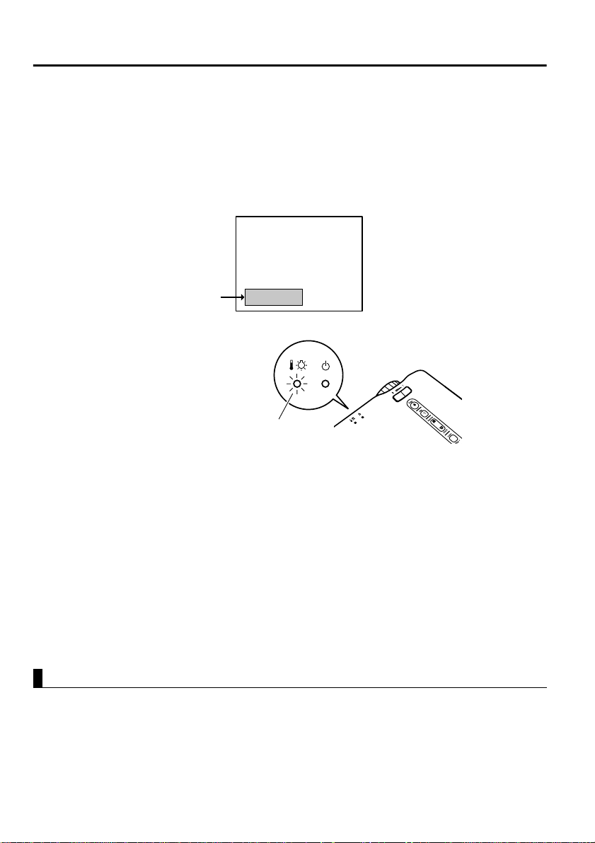
The Remote Control Does Not Operate
• Is the remote control R/C switch set to On? See page 25
• Are you pointing the remote control in the correct
direction for operation? See page 11
The range of operation is app roximately 30° left or right and
approximately 15° above or below the r emote control sens or
on the projector.
• Is the remote control too far from the projector?
See page 11
The operable distance is approximately 393.70inches (10m ).
• Is the remote control receiver on the projector blocked?
• Is the remote control receiver in the path of direct
sunlight or strong fluorescent light?
• Are batteries in place? See page 12
• Are the batteries worn? See page 12
• Are the batteries inserted correctly? See page 12
Cannot Switch off (After Pressing the Power Button)
OFF
• The operation display indicator remains a steady
orange.
The operation display indicator of the projector is designed
to remain lit even after power is switched off.
When the plug is pulled out of the outlet, the operation
display indicator will go out.
• The fan does not stop.
After the Power button is pressed and power is turned off,
cool-down
After cool-down, the operation display indicator lights
orange, and you should pull the plug out of the outlet.
* Cool-down time takes about 2 minutes.
* begins.
61
Page 64

Page 65

Maintenance
Projector Cleaning, Lens Replacement,
Air Inlet Cleaning.................................................64
Lamp Replacement.................................................66
63
Page 66

Projector Cleaning, Lens Replacement, Air Inlet Cleaning
Clean your projector when it is dirty or image projection is poor. Clean the air
inlets every 100 hours in practice.
Warning:
• The projector cabinet should only be opened by trained service personnel. The
projector contains several high voltage components which can cause electric shock.
For internal checks, repairs and cleaning, contact your dealer or the nearest ad dress
provided at “Internat ional Warr anty Conditio ns” in “Safety In structions/ World-Wide
Warranty Terms” included in the package.
• Use care when handling the power plug and connector. Improper handling may
cause fire or electric shock. When handling the plug, observe the following.
· Do not insert a plug or connector into an ou tlet or port if it is dirty or hol d s for ei gn
matter.
· Insert the plug and connector firmly and completely.
· Do not pull out the plug or connector with wet hands.
Caution:
• Never attempt to remove the lamp immediately after use.
· Heat may cause burns or other injury.
· Wait approximately 60 minutes after switc hing of f power and remo ve the la mp after
the projector has cooled completely.
• When performing operations, pull the pow er p lug an d connector out of the outlet and
port respectively.
Switch off power to the projector and disconnect the power cord before
cleaning.
Cleaning the Projector Unit
•Wipe dirt from the projector lightly with a soft cloth.
•For heavier dirt, wipe the projector lightly with a cloth soaked in a weak
solution of mild detergent and wrung out thoroughly, t hen d ry with a separate
cloth.
Do not use waxes, benzene , thinners, or other volat il e substances. These may
degrade the cabinet or strip the finish.
Cleaning the Lens
Clean the lens with a commercial blo wer or lens cleaning paper. Th e surface of
the lens is easily scratched and should not be rubbed or struck with hard
objects.
64
Page 67
Cleaning the Air Inlets
Accumula ted dust in the air inlets deg r ades ventilation, increa ses the interi or
temperature, and can cause malfunct io n.
To prevent debris from entering the air inlets, always stand the projector
upright with the lens upward. Then use a vacuum cleane r or other equipment to
suck dust from the inlets.
Tip:
If it is no longer possible to remove the dirt from the air inlets, it is time to replace
them. Consult your vendor.
65
Page 68
Lamp Replacement
Replace the lamp with a new lamp in the following instances.
A replacement lamp is an optional pa rt (sold separately).
(Model No: ELPLP16)
[When the following message is displayed for 30 seconds after projection
begins: "Lamp Replace. After the re placement of the lamp, reset the lamp
timer under the direction in the user’s manual."]
A message will be displayed.
[When the problem/alarm display indicator flashes red at 1-second intervals.]
Problem/alarm display indicator
flashes red at 1-second intervals
[When brightness or picture quality is inferior to its original st ate.]
Tip:
• If the lamp does not light, replace it even if the lamp life has not expired.
• To maintain the original brightness and picture qua lity, rep lacement messa ges are set
for approximately 1,400 hours.
If you continue to use the lamp after this period, the possibility of the lamp breaking
becomes greater. When the lamp replacement message appears, replace the lamp
with a new one as soon as possible, even if it is still working.
• Though a replacement message appears at approximately 1,400 hours, individual
lamp characteristics or usage conditions may cause failure before 1,400 hours, and
we recommend that a replacement lamp be kept on hand.
• Contact your dealer for a spare lamp.
Replacement
Tip:
• Install the lamp securely. For safety, when the lamp cover is opened, the abnormal
warning display indica tor flashes re d, and the projecto r lamp goes out. If the lamp or
lamp cover is installed improperly, the lamp will not light.
66
Page 69

1.
Switch off power to the projector and
disconnect the po wer cor d after cool-down
ends.
Cool-down time varies ac cording to externa l
temperature and other factors.
2.
After the projector has cooled comp letely,
remove the lamp cover.
•The projector requires approximately 60
minutes to cool completely.
•Press on the 2 catches and pull the cover
out diagonally.
3.
Pull the lamp out.
Use a screwdriver to loosen the two lam p
retaining screws, then grasp the holds and
pull the lamp out.
*
4.
Install a ne w lamp.
Align the lamp properly, insert the lamp
until it contacts the rear of the housing, and
use a screwdriver to tighten the two lamp
retaining screws firmly.
5.
Install the lamp cover.
Insert the cover diagonally and press it into
the projector un til you hea r the ca tches click
into place.
Check that the catches ar e securely fastened.
Tip:
After lamp replacement, use the About menu to
reset lamp time to its initial value (See page 50).
67
Page 70

Page 71

General Notes
Optional Accessories..............................................70
Glossary..................................................................71
Specifications..........................................................73
External Dimensions...............................................75
Index.......................................................................76
69
Page 72

Optional Accessories
The following optional accessories are available for purchase if required.
Details of optional accessories listed here are current as of November 2001.
Details of accessories are subject to change without notice.
Soft carrying case ELPKS16
(type for storing a laptop computer)
Use this case if you need to carry the projector
by hand.
Soft carrying case ELPKS24
Use this case if you need to carry the projector
by hand.
Spare lamp ELPLP16
Use as a replacement for spent lamps.
Portable screen (50 inch) ELPSC06
A compact screen which can be carried easily.
60 inch screen ELPSC07
80 inch screen ELPSC08
Mac adapter set ELPAP01
Use to connect the projector to a Macintosh
computer when the accessory or optional
computer cables cannot be used because the
connector shapes are different.
Computer cable ELPKC02
(6 ft (1.8 m) - for mini D-Sub 15-pin/mini
D-Sub 15-pin)
Use to connect the projector to a computer
when you would like to use UXGA display
resolution.
Computer cable ELPKC09
(9.8 ft (3 m) - for mini D-Sub 15-pin/mini
D-Sub 15-pin)
Computer cable ELPKC10
(65.6 ft (20 m) - for mini D-Sub 15-pin/
mini D-Sub 15-pin)
Use this extension cable if the accessory
computer cable is too short.
Component video cable ELPKC19
(9.8 ft (3 m) - for mini D-Sub 15-pin/RCA
x 3)
Use to connect a component video source.
Image presentation camer a ELPDC02
ELPDC03
Use when projecting books, OHP films and
slides.
70
Page 73

Glossary
This glossary provides brief explanations of terms which are used in this
manual but are not explained in the text or difficult to understand. For details,
refer to other available publications.
Term Description
A/V Mute Refers to temporary stoppage of audio and video. Your projector
Aspect ratio The ratio between an image's length and its height. HDTV images
Color
difference
signal
(component)
Color
temperature
Contrast The enhancing or weakening of differences in color lightness and
Cool-Down After the Power button is pressed and the lamp goes out, lamp
Gamma During image displ ay, the di fferenc e of dis play c olors d ependi ng o n
SVGA Refers to a 800-pixel (Pix) horizontal x 600-pixel (Pix) vertical
SXGA Refers to a 1280-pixel (Pix) horizontal x 1024-pixel (Pix) vertical
Sync
(synchronization)
provides this function when the A/V Mute button is pressed. When
the A/V Mute button is pressed again or audio volume is adjusted,
this function is released.
have an aspect ratio of 16:9 an d appear elongat ed. The aspect rati o
for standard images is 4:3.
A type of video signal output by video equipment which actually
consists of three s eparate s ignals: a re d + lum inance sig nal (R-Y), a
luminance signal (Y) and a blue + luminance signal (B-Y). Each
signal is transmitted along a separate cable. Color difference
signals generally res ult in a bet ter image than com posi te signa ls (in
which the red, green and blu e si gn als and the luminance signal are
all transmitted along a single cable).
The temperature of an object which is emitting light. If the color
temperature is high, the colors tend to take on a bluish tinge. If the
color temperature is lower, the colors tend to take on a reddish tinge.
darkness that provides a sharper or softer view of characters and
images. This adjustment is referred to as contrast adjustment.
cooling is continued. After the lamp goes out, a cooling fan spins,
and operational buttons become inactive.
Cool-down time takes about 2 minutes.
the device used is compensated.
display signal for an IBM PC/AT-compatible (DOS/V) computer.
display signal for an IBM PC/AT-compatible (DOS/V) computer.
Signals output b y a c om pute r are output at a certai n p r ede term in ed
frequency.
If the frequency of your projector cannot match that frequency, a
clear image cannot be obtained. Matching of signal phases (peak
offset) is referred to as synchronization (synch).
If synchronization is not achieved, a projected image displays
jitters, blurring, an d horizontal noise.
71
Page 74

Term Description
Tracking Signals output by a computer are output at a certain predete rmine d
USB An abbreviation for universal serial bus, an interface for connecting
VGA Refers to a 640-pixel (Pix) horizontal x 480-pixel (Pix) vertical
XGA Refers to a 1024-pixel (Pix) horizontal x 768-pixel (Pix) vertical
YCbCr The carrier signal which is contained in the color bar signal used in
YPbPr The carrier signal which is contained in the color bar signal used in
YUV This signal consists of three components, the luminance (Y), red
frequency.
If the frequency of your projector cannot match that frequency, a
clear image cannot be obtained. Matching of signal frequencies is
referred to as matching tracking. When tracking is not matched, a
projected image displays broad vertical bands.
a personal computer with a relatively low-speed peripheral device.
display signal for an IBM PC/AT-compatible (DOS/V) computer.
display signal for an IBM PC/AT-compatible (DOS/V) computer.
modern TV transmissions (NTSC format). The name comes from
the Y (luminance) signal and the CbCr (chroma [color]) signals.
high-definition TV (HDTV) transmissions. The name comes from
the Y (luminance) signal and the PbPr (color difference) signals.
minus luminance (U) and blue minus luminance (V).
The human eye is more sensitive for changes in brightness than
changes in color. By us ing this fe ature, the da ta volume assigned to
the brightness is larger. To prevent a deterioration of the image
quality, a high data compression rate is used.
This signal format is used for digital video data.
72
Page 75

Specifications
Product Name Multi-Media Projector EMP-71/51
Dimensions 11.81(W) x 3.15(H) x 8.46(D)inches
Panel Size 0.7
Display Format Polysilicon TFT
Pixel Count
Focus Adjustment Manual
Zoom Adjustment Electronic 0.8 : 1
Lamp (Light Source) UHE lamp, Rated 160W ELPLP16
Maximum Audio Output 1W monaural
Speaker 1
Power Supply 100 – 240VAC 50/60Hz
Power Cons umption 2.9A – 1.6A
Usage Temperature
Range
Storage Temperature
Range
Weight Approx. 6.83lb (3.1kg)
Connectors
(300(W) x 80(H) x 220(D)mm)
(not including protruding parts)
<EMP-71> 786,432 (1,024 (Horizontal) x 768 (Vertical) dots) x 3
<EMP-51> 480,000 (800 (Horizontal) x 600 (Vertical) dots) x 3
41°F – 95°F (+5°C – +35°C) (No condensation)
14°F – 140°F (-10°C – +60°C ) (No condensation)
Computer/Component
Video port
Audio In
(for computer)
Mouse/Com
Composite Video
S-Video
Audio
(for video)
Audio Out
USB Mouse
port
port
port
s
port
port
port
1 system Mini D-Sub 15-pin
1 system Stereo mini-jack
1 system DIN jack, 9-pin
port
1 system RCA pin jack
1 system Mini DIN, 4-pin
1 system RCA pin jack
1 system Stereo mini-jack
1 system USB connector
Specifications may change without notice.
(female)
x2 (L, R)
(B-type)
73
Page 76

Safety
USA
UL1950 3
rd
Edition
Canada
CSA C22. 2 No.950-9 5 (c U L )
European Community
The Low Voltage Directive (73/23/EEC)
IEC60950 2
nd
Edition, +Amd.1, +Amd.2, +Amd.3, +Amd.4
EMC
USA
FCC 47CFR Part15B Class B (DoC)
Canada
ICES-003 Class B
European Community
The EMC Directive (89/336/EEC)
EN55022, 1998 Class B
EN55024, 1998
IEC61000-4-2, IEC61000-4-3, IEC61000-4-4, IEC61000-4-5,
IEC61000-4-6, IEC61000-4-8, IEC61000-4-11,
IEC61000-3-2, IEC61000-3-3
Australia/New Zealand
AS/NZS 3548:1995, A1:1997, A2:1997 Class B
CISPR Pub.22:1993, A1:1995, A2:1996, Class B
74
Page 77

External Dimensions
9.06
(230)
3.15
(80)
3.90
(99)
11.81 (300)
Units: inch (mm)
75
Page 78

Index
[A]
A/V Device . . . . . . . . . . . . . . 21
A/V Mute . . . . . . . . . . . . . . . . 48
A/V Mute Button . . . . . . . 10, 39
About Menu . . . . . . . . . . . . . . 50
Adjusting . . . . . . . . . . . . . 28, 30
Advanced Menu . . . . . . . . . . . 49
Air Inlet. . . . . . . . . . . . . . . . . . . 8
Aspect Ratio . . . . . . . . . . . . . . 44
Audio In Port . . . . . . . . . . . 9, 20
Audio Input . . . . . . . . . . . . . . 45
Audio Menu . . . . . . . . . . . . . . 45
Audio Out Port . . . . . . . . . . 9, 23
Audio Ports . . . . . . . . . . . . 9, 21
Auto Button . . . . . . . . . . . 10, 30
Auto Setup . . . . . . . . . . . . . . . 44
[B]
Battery Cover . . . . . . . . . . 10, 12
Brightness . . . . . . . . . . . . . . . 44
[C]
Ceiling . . . . . . . . . . . . . . . . . . 49
Color . . . . . . . . . . . . . . . . . . . 44
Color Setting . . . . . . . . . . . . . 49
Compatible Mode . . . . . . . . . 19
Computer . . . . . . . . . . . . . . . . 18
Computer Button . . . . . . . 10, 26
Computer/Component Video
Port . . . . . . . . . . . . . . . . . 9, 20
Connecting . . . . . . . . . . . . 20, 21
Contrast . . . . . . . . . . . . . . . . . 44
Control Panel . . . . . . . . . . . . . 12
Cursor Speed . . . . . . . . . . . . . 46
Cursor/Stamp . . . . . . . . . . 38, 46
[E]
Effect Button . . . . . . . . . . 10, 38
Effect Menu . . . . . . . . . . . . . . 46
Enter Button . . . . . 10, 34, 40, 42
Esc Button . . . . . . . . . 10, 34, 42
External Audio Device . . . . . 23
External Dimensions. . . . . . . . 75
E-Zoom Button . . . . . . . . 10, 36
[F]
Focus Ring . . . . . . . . . . . . . 8, 29
Foot Adjust Lever . . . . . . . . . . 8
Freeze Button . . . . . . . . . . 10, 39
Frequency . . . . . . . . . . . . . . . 50
Front Adjustable Foot . . . . 8, 28
[G]
Gamma . . . . . . . . . . . . . . . . . . 44
[H]
Help Button . . . . . . . . . 9, 10, 40
Help Screens . . . . . . . . . . . . . 40
Horizontal Bar . . . . . . . . . 38, 46
[I]
Indicator . . . . . . . . . . . . . . . . . 10
Initial Settings . . . . . . . . . . . . 52
Input Signal . . . . . . . . . . . 44, 50
Input/Output Ports . . . . . . . . . . 8
Inserting Batteries . . . . . . . . . 12
[K]
Keystone . . . . . . . . . . . . . . . . 47
Keystone (Select)
Button . . . . . . . . . . . . 9, 29, 40
[L]
Lamp . . . . . . . . . . . . . . . . . . . 50
Lamp Cover . . . . . . . . . . . . . . . 8
Lamp Replacement . . . . . . . . 66
Language . . . . . . . . . . . . . . . . 49
Laptop . . . . . . . . . . . . . . . . . . 27
Lens Cover . . . . . . . . . . . . . . . . 8
76
Page 79

[M]
Macintosh . . . . . . . . . . . . . . . 35
Menu Button . . . . . . . . . . 10, 42
Mode . . . . . . . . . . . . . . . . 44, 50
Mouse Cable . . . . . . . . . . . . . 35
Mouse/Com Port . . . . . . . . 9, 35
[N]
No-signal . . . . . . . . . . . . . . . . 47
[O]
Operation Display
Indicator . . . . 8, 24, 25, 31, 54
Optional Accessories . . . . . . . 70
[P]
Position . . . . . . . . . . . . . . . . . 43
Power Button . . . . . 9, 10, 25, 31
Power Cord . . . . . . . . . . . . . . 24
Power Inlet . . . . . . . . . . . . . 8, 24
Problem/Alarm Display
Indicator . . . . . . . . . . . 8, 55, 66
Projection Distance . . . . . . . . 16
Prompt . . . . . . . . . . . . . . . . . . 47
PS/2 Mouse Cable . . . . . . . . . 35
[R]
R/C Switch . . . . . . . . . 10, 25, 32
Rear Adjustable Foot . . . . . . . . 8
Rear Projection . . . . . . . . . . . 49
Refresh Rate . . . . . . . . . . . . . 50
Remote Control . . . . . . . . 10, 11
Remote Control Receiver . . . . 8
Reset . . . . . . . 44, 45, 46, 48, 49
Reset All Menu . . . . . . . . . . . 51
Reset Lamp Timer . . . . . . . . . 50
Resolution . . . . . . . . . . . . . . . 50
[S]
Screen Size . . . . . . . . . . . . . . .16
Setting Menu . . . . . . . . . . . . . .47
Setup Instructions . . . . . . . . . .15
Sharpness . . . . . . . . . . . . . . . . .44
Sleep Mode . . . . . . . . . . . . . . .48
Source (Enter) Button . .9, 26, 40
Speaker . . . . . . . . . . . . . . . . . . .8
Special Notes on Setup . . . . . .14
Specifications . . . . . . . . . . . . . .73
Storage . . . . . . . . . . . . . . . . . . .32
S-Video Button . . . . . . . . .10, 26
S-Video Port . . . . . . . . . . . .9, 21
SYNC Mode . . . . . . . . . . . . . .50
SYNC Polarity . . . . . . . . . . . . .50
Sync. . . . . . . . . . . . . . . . . . . . .43
[T]
Term . . . . . . . . . . . . . . . . . . . . .71
Tint . . . . . . . . . . . . . . . . . . . . . .44
Tone . . . . . . . . . . . . . . . . . . . . .45
Tracking . . . . . . . . . . . . . . . . . .43
[U]
USB mouse Cable . . . . . . . . . .35
USB mouse Port . . . . . . . . .9, 35
[V]
Video Button . . . . . . . . . . .10, 26
Video Menu . . . . . . . . . . . . . . .43
Video Source . . . . . . . . . . . . . .50
Video Port . . . . . . . . . . . . . . . .21
Volume . . . . . . . . . . . . . . . . . .45
Volume Button . . . . . . . . .10, 30
[W]
Wide/Tele Button . . . . . . . .8, 37
Windows . . . . . . . . . . . . . . . . .35
Wireless Mouse . . . . . . . . . . . .34
77
Page 80

FCC Compliance Statement
For United States Users
This equipment has been tested and found to comply with the limits
for a Class B digital device, pursuant to Part 15 of the FCC Rules.
These limits are designed to provide reasonable protection against
harmful interference in a residential installation. This equipment
generates, uses, and can radiate radio frequency energy and, if not
installed and used in accordance with the instruct ions, may cause
harmful interference to radio or television reception. However, there
is no guarantee that interference will not occur in a particular
installation. If this equipment does cause interference to radio and
television reception, which can be determined by turning the
equipment off and on, the user is encouraged to try to correct the
interference by one or more of the following measures.
• Reorient or relocate th e receiving antenna.
• Increase the separation between the equi pment and receiver.
• Connect the equipment into an outl et on a circuit dif ferent from that
to which the receiver is connected.
• Consult the dealer or an experienced radi o/TV technician for help.
WARNING
The connection of a non-shielded equipment interface cable to t his
equipment will invalidate the FCC Certification or Declaration of this
device and may cause interference levels which exceed the li mits
established by the FCC for this equipment. It is the responsibility of
the user to obtain and use a shielded equipment interface cable wit h
this device. If this equipment has more than one interface connector,
do not leave cables connected to unused interfaces. Changes or
modifications not expressly a pproved by th e manufacturer cou ld void
the user’s authority to operate the equipment.
Declaration of Conformity for Products Marked the FCC Logo
(United States only)
For questions regarding your product, contact:
EPSON AMERICA, INC.
MS 3-13
3840 Kilroy Airport Way
Long Beach, CA 90806
Telephone: 562-290-5254
Page 81

All rights reserved. No part of this publication may be reproduced, stored in a
retrieval system, or transmitted in any form or by any means, electronic,
mechanical, photocopying, recording, or otherwise, without the prior written
permission of SEIKO EPSON CORPORATION. No patent liability is assumed
with respect to the use of the information contained herein. Neither is any liability
assumed for damages resulting from the use of the information contained herein.
Neither SEIKO EPSON CORPORATION nor its affiliates shall be liable to the
purchaser of this product or third parties for damages, losses, costs, or expenses
incurred by purchaser or third parties as a result of: accident, misuse, or abuse of
this product or un authorized modi fications, repairs, or alteratio ns to this p roduct, o r
(excluding the U.S.) failure to strictly comply with SEIKO EPSON
CORPORATION’s operating and maintenance instructions.
SEIKO EPSON CORPORATION shall not be liable against any damages or
problems a rising from the use of any options or any consumable products other
than those designated as Original EPSON Products or EPSON Approved Products
by SEIKO EPSON CORPORATION.
EPSON is a registered trademark and PowerLite is a trademark of SEIKO EPSON
CORPORATION.
General Notice: The following trademarks and registered trademarks are the
property of their respective owners and are used in this publication for
identification purposes only.
• EPSON/Seiko Epson Corp.
• Macintosh, PowerBook/Apple Computer Inc.
• IBM/International Business Machine Corp.
• Windows/Microsoft Corp.
Other product names used herein are al s o for i denti ficat i on purposes only and may
be trademarks of their respective owners. EPSON disclaims any and all rights in
those marks.
Copyright 2001 by SEIKO EPSON CORPORATION
Page 82

Printed in Japan
402029000
(9002201)
01.11-.7A(C05)
 Loading...