

Page 1
Operating manual
Draft
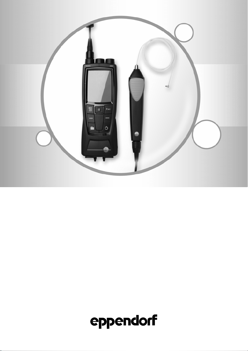
Temperature Verification System USB Singlechannel
see
on p.Fig.Tab.p
.
Operating manual
0056000402
Temperature Verification System USB
Single-channel
Operating manual
Page 2

Operating manual
Copyright© 2012 Eppendorf AG, Hamburg. No part of this publication may be reproduced
without the prior permission of the copyright owner.
eppendorf® Mastercycler® and vapoprotect® are registered trademarks of Eppendorf AG,
Hamburg, Germany.
Trademarks are not marked in all cases with ™ or ® in this manual.
2
Page 3

Temperature Verification System USB – Single-channel — Operating manual
Table of contents
1 Table of contents
1 Operating instructions . . . . . . . . . . . . . . . . . . . . . . . . . . . . . . . . . . . . . . . . . . . . . . . . . . . . 5
1.1 Using this manual. . . . . . . . . . . . . . . . . . . . . . . . . . . . . . . . . . . . . . . . . . . . . . . . . . . . . 5
1.2 Danger symbols and danger levels . . . . . . . . . . . . . . . . . . . . . . . . . . . . . . . . . . . . . . . 5
1.2.1 Danger symbols . . . . . . . . . . . . . . . . . . . . . . . . . . . . . . . . . . . . . . . . . . . . . . . . 5
1.2.2 Danger levels . . . . . . . . . . . . . . . . . . . . . . . . . . . . . . . . . . . . . . . . . . . . . . . . . . 5
1.3 Symbols used. . . . . . . . . . . . . . . . . . . . . . . . . . . . . . . . . . . . . . . . . . . . . . . . . . . . . . . . 6
1.4 Abbreviations used. . . . . . . . . . . . . . . . . . . . . . . . . . . . . . . . . . . . . . . . . . . . . . . . . . . . 6
1.5 Glossary . . . . . . . . . . . . . . . . . . . . . . . . . . . . . . . . . . . . . . . . . . . . . . . . . . . . . . . . . . . . 6
2 Product description . . . . . . . . . . . . . . . . . . . . . . . . . . . . . . . . . . . . . . . . . . . . . . . . . . . . . . 7
2.1 Delivery package . . . . . . . . . . . . . . . . . . . . . . . . . . . . . . . . . . . . . . . . . . . . . . . . . . . . . 7
2.1.1 Temperature Verification System USB – Single-channel . . . . . . . . . . . . . . . . . 7
2.1.2 Temperature sensor 96 Well. . . . . . . . . . . . . . . . . . . . . . . . . . . . . . . . . . . . . . . 7
2.1.3 Temperature sensor 384 Well. . . . . . . . . . . . . . . . . . . . . . . . . . . . . . . . . . . . . . 7
2.1.4 Temperature sensor 1,5 mL . . . . . . . . . . . . . . . . . . . . . . . . . . . . . . . . . . . . . . . 7
2.2 Features . . . . . . . . . . . . . . . . . . . . . . . . . . . . . . . . . . . . . . . . . . . . . . . . . . . . . . . . . . . . 7
2.2.1 Temperature Verification System USB – Single-channel . . . . . . . . . . . . . . . . . 7
2.2.2 Design of the temperature sensor. . . . . . . . . . . . . . . . . . . . . . . . . . . . . . . . . . . 8
2.2.3 Temperature sensor 96 Well. . . . . . . . . . . . . . . . . . . . . . . . . . . . . . . . . . . . . . . 8
2.2.4 Temperature sensor 384 Well. . . . . . . . . . . . . . . . . . . . . . . . . . . . . . . . . . . . . . 9
2.2.5 Temperature sensor 1,5 mL . . . . . . . . . . . . . . . . . . . . . . . . . . . . . . . . . . . . . . . 9
2.3 Certificate . . . . . . . . . . . . . . . . . . . . . . . . . . . . . . . . . . . . . . . . . . . . . . . . . . . . . . . . . . . 9
3 Safety . . . . . . . . . . . . . . . . . . . . . . . . . . . . . . . . . . . . . . . . . . . . . . . . . . . . . . . . . . . . . . . . . 10
3.1 Intended use. . . . . . . . . . . . . . . . . . . . . . . . . . . . . . . . . . . . . . . . . . . . . . . . . . . . . . . . 10
3.2 User profile . . . . . . . . . . . . . . . . . . . . . . . . . . . . . . . . . . . . . . . . . . . . . . . . . . . . . . . . . 10
3.3 Information on product liability . . . . . . . . . . . . . . . . . . . . . . . . . . . . . . . . . . . . . . . . . . 10
3.4 Warnings for intended use . . . . . . . . . . . . . . . . . . . . . . . . . . . . . . . . . . . . . . . . . . . . . 10
3.5 Warnings for unintended use . . . . . . . . . . . . . . . . . . . . . . . . . . . . . . . . . . . . . . . . . . . 12
4 Installation . . . . . . . . . . . . . . . . . . . . . . . . . . . . . . . . . . . . . . . . . . . . . . . . . . . . . . . . . . . . . 13
4.1 Initial charging of the battery . . . . . . . . . . . . . . . . . . . . . . . . . . . . . . . . . . . . . . . . . . . 13
4.2 Connecting the temperature sensor to the Measuring device . . . . . . . . . . . . . . . . . . 13
4.3 Connecting the Mastercycler nexus . . . . . . . . . . . . . . . . . . . . . . . . . . . . . . . . . . . . . . 14
4.4 Connecting the Mastercycler pro . . . . . . . . . . . . . . . . . . . . . . . . . . . . . . . . . . . . . . . . 15
4.5 Connecting the Mastercycler ep. . . . . . . . . . . . . . . . . . . . . . . . . . . . . . . . . . . . . . . . . 16
4.6 Connecting the Mastercycler pro 384 and Mastercycler ep 384. . . . . . . . . . . . . . . . . 16
4.6.1 Connecting the Mastercycler pro 384 . . . . . . . . . . . . . . . . . . . . . . . . . . . . . . . 16
4.6.2 Connecting the Mastercycler ep 384 . . . . . . . . . . . . . . . . . . . . . . . . . . . . . . . 16
4.6.3 Preparing the Thermoblock 384 . . . . . . . . . . . . . . . . . . . . . . . . . . . . . . . . . . . 17
4.6.4 Removing oil . . . . . . . . . . . . . . . . . . . . . . . . . . . . . . . . . . . . . . . . . . . . . . . . . . 18
4.7 Connecting the Mastercycler to a computer and CycleManager pro/pro
XL
. . . . . . . . 18
3
Page 4

Temperature Verification System USB – Single-channel — Operating manual
4.8 Installing the Thermomixer and ThermoStat . . . . . . . . . . . . . . . . . . . . . . . . . . . . . . . 18
4.8.1 Preparing the Thermomixer comfort and ThermoStat plus. . . . . . . . . . . . . . . 18
4.8.2 Connecting the Thermomixer and ThermoStat. . . . . . . . . . . . . . . . . . . . . . . . 18
5 Operation . . . . . . . . . . . . . . . . . . . . . . . . . . . . . . . . . . . . . . . . . . . . . . . . . . . . . . . . . . . . . . 19
5.1 Verifying the Mastercycler nexus, pro and ep. . . . . . . . . . . . . . . . . . . . . . . . . . . . . . . 20
5.1.1 Overview . . . . . . . . . . . . . . . . . . . . . . . . . . . . . . . . . . . . . . . . . . . . . . . . . . . . . 20
5.1.2 Verifying the Mastercycler nexus and Mastercycler pro . . . . . . . . . . . . . . . . . 20
5.1.3 Verifying the Mastercycler ep . . . . . . . . . . . . . . . . . . . . . . . . . . . . . . . . . . . . . 22
5.1.4 Verifying the Mastercycler pro/ep using the CycleManager pro . . . . . . . . . . . 23
5.2 Adjusting the Mastercycler nexus/pro/ep . . . . . . . . . . . . . . . . . . . . . . . . . . . . . . . . . . 25
5.2.1 Overview . . . . . . . . . . . . . . . . . . . . . . . . . . . . . . . . . . . . . . . . . . . . . . . . . . . . . 25
5.2.2 Adjusting the Mastercycler nexus and Mastercycler pro . . . . . . . . . . . . . . . . . 25
5.2.3 Adjusting the Mastercycler ep. . . . . . . . . . . . . . . . . . . . . . . . . . . . . . . . . . . . . 27
5.2.4 Adjusting the Mastercycler pro/ep using the CycleManager pro. . . . . . . . . . . 28
5.3 Verifying the Thermomixer and ThermoStat. . . . . . . . . . . . . . . . . . . . . . . . . . . . . . . . 30
6 Troubleshooting . . . . . . . . . . . . . . . . . . . . . . . . . . . . . . . . . . . . . . . . . . . . . . . . . . . . . . . . 31
6.1 General errors . . . . . . . . . . . . . . . . . . . . . . . . . . . . . . . . . . . . . . . . . . . . . . . . . . . . . . 31
6.1.1 Troubleshooting for the Measuring device . . . . . . . . . . . . . . . . . . . . . . . . . . . 31
6.1.2 Troubleshooting for the Mastercyclers . . . . . . . . . . . . . . . . . . . . . . . . . . . . . . 31
7 Transport, storage and disposal . . . . . . . . . . . . . . . . . . . . . . . . . . . . . . . . . . . . . . . . . . . 32
7.1 Packing. . . . . . . . . . . . . . . . . . . . . . . . . . . . . . . . . . . . . . . . . . . . . . . . . . . . . . . . . . . . 32
7.2 Disposal . . . . . . . . . . . . . . . . . . . . . . . . . . . . . . . . . . . . . . . . . . . . . . . . . . . . . . . . . . . 32
8 Maintenance . . . . . . . . . . . . . . . . . . . . . . . . . . . . . . . . . . . . . . . . . . . . . . . . . . . . . . . . . . . 33
8.1 Servicing the Measuring device . . . . . . . . . . . . . . . . . . . . . . . . . . . . . . . . . . . . . . . . . 33
8.2 Servicing the Temperature sensor . . . . . . . . . . . . . . . . . . . . . . . . . . . . . . . . . . . . . . . 33
8.3 Removing oil from the thermoblock . . . . . . . . . . . . . . . . . . . . . . . . . . . . . . . . . . . . . . 33
8.4 Disinfection/Decontamination. . . . . . . . . . . . . . . . . . . . . . . . . . . . . . . . . . . . . . . . . . . 33
8.5 Decontamination before shipment . . . . . . . . . . . . . . . . . . . . . . . . . . . . . . . . . . . . . . . 34
9 Technical data . . . . . . . . . . . . . . . . . . . . . . . . . . . . . . . . . . . . . . . . . . . . . . . . . . . . . . . . . . 34
9.1 Temperature Verification System USB – Single-channel . . . . . . . . . . . . . . . . . . . . . . 34
9.2 Mastercycler, Thermomixer and ThermoStat . . . . . . . . . . . . . . . . . . . . . . . . . . . . . . . 34
9.3 Maximum permissible errors and accuracy . . . . . . . . . . . . . . . . . . . . . . . . . . . . . . . . 34
9.3.1 Temperature Verification System USB – Single-channel . . . . . . . . . . . . . . . . 34
9.3.2 Mastercycler . . . . . . . . . . . . . . . . . . . . . . . . . . . . . . . . . . . . . . . . . . . . . . . . . . 35
9.3.3 Thermomixer and ThermoStat . . . . . . . . . . . . . . . . . . . . . . . . . . . . . . . . . . . . 35
9.3.4 ThermoMixer C, ThermoMixer F1.5, ThermoMixer FP and ThermoStat C. . . 35
10 Ordering information . . . . . . . . . . . . . . . . . . . . . . . . . . . . . . . . . . . . . . . . . . . . . . . . . . . . 36
Index. . . . . . . . . . . . . . . . . . . . . . . . . . . . . . . . . . . . . . . . . . . . . . . . . . . . . . . . . . . . . . . . . . 37
4
Page 5
Temperature Verification System USB – Single-channel — Operating manual
1 Operating instructions
1 Operating instructions
1.1 Using this manual
Read this operating manual completely before using the device for the first time. Please also
note the operating instructions for the accessories, if applicable.
This operating manual is part of the product. Please keep it in a place that is easily
accessible.
Enclose this operating manual when transferring the device to third parties.
If this manual is lost, please request another one. For the current version, please refer to our
webpage www.eppendorf.com/worldwide
America).
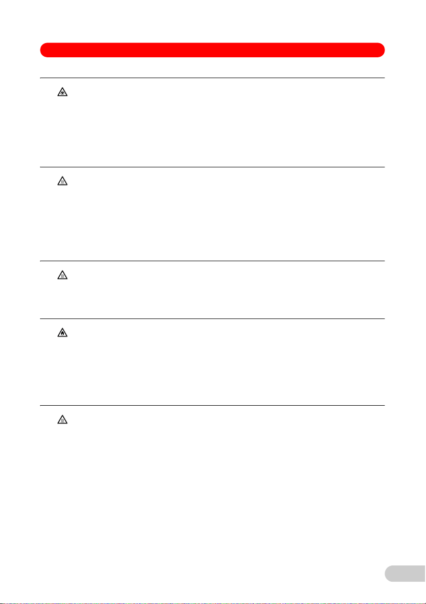
1.2 Danger symbols and danger levels
The safety instructions in this manual appear with the following danger symbols and danger
levels:
1.2.1 Danger symbols
Biohazard Explosion
Electric shock Hot surface
(international) or www.eppendorfna.com (North
Hazard point Material damage
1.2.2 Danger levels
DANGER Will lead to serious injuries or death.
WARNING May lead to serious injuries or death.
CAUTION May lead to light to moderate injuries.
NOTICE May lead to material damage.
5
Page 6
Temperature Verification System USB – Single-channel — Operating manual
1.3 Symbols used
Symbol Meaning
Handling
1.
2.
Actions in the specified order
• List
Text Name of fields in the software
Useful information
1.4 Abbreviations used
PDF Portable document format
USB Universal serial bus
1.5 Glossary
A
Adjustment Tuning or alignment of a device to prevent systematic deviations to the extent
required for the observance of specifications. An adjustment requires an
intervention that permanently modifies the device.
T
Temperature
accuracy
Temperature
homogeneity
Verification Objective proof of the observance of defined specifications.
Deviation of the measured temperature from the specified temperature at a
given position on the thermoblock.
Maximum temperature difference between two positions of the thermoblock.
V
6
Page 7

Temperature Verification System USB – Single-channel — Operating manual
2 Product description
2 Product description
2.1 Delivery package
2.1.1 Temperature Verification System USB – Single-channel
For Mastercycler nexus, Mastercycler pro, Mastercycler ep, Thermomixer and ThermoStat
1× measuring device
1× plug head line (connecting cable between measuring device and temperature sensor)
1× mains/power supply device
4× international plug adapter
1× operating manual
1× device case
2.1.2 Temperature sensor 96 Well
1× Temperature sensor 96 Well
1× certificate
2.1.3 Temperature sensor 384 Well
1× Temperature sensor 384 Well
1× silicone mat for the Temperature sensor 384 Well
4× spacers
1× bottle with parrafin oil (25 mL)
1× certificate
2.1.4 Temperature sensor 1,5 mL
1× Temperature sensor 1,5 mL
1× certificate
2.2 Features
2.2.1 Temperature Verification System USB – Single-channel
Hint!
• The term "validation" has been replaced by "verification" in these
instructions. The term "validation" is still used in older software versions.
• The term "calibration" has been replaced by "adjustment" in these
instructions. The term "calibration" is still used in older software versions.
The Temperature Verification System USB – Single-channel enables simple and fast inspection
of the block temperature of the following Mastercycler products:
• Mastercycler nexus
• Mastercycler pro
• Mastercycler ep
The Temperature Verification System USB – Single-channel requires a minimum software
version in the control panel of the thermal cycler.
This table contains the minimum software versions required to use the Temperature Verification
System USB – Single-channel. If the device or CycleManager pro software has an older version,
install the software version listed below.
7
Page 8

Temperature Verification System USB – Single-channel — Operating manual
Device Software version
Mastercycler nexus 1.4.0.0
Mastercycler pro 1.023
Mastercycler ep 4.605
CycleManager pro/pro
The Mastercyclers listed feature a precise system which meets all of the laboratory requirements
for documentation and the obligation to provide supporting documentation.
Furthermore, the block temperature of the Eppendorf Thermomixer and ThermoStat devices can
be measured using the Temperature sensor 1,5 mL and Temperature sensor 384 Well.
The Temperature Verification System USB – Single-channel consists of a digital display device
with connected temperature sensor. Various temperature sensors, which are geometrically
adapted to the various thermoblock bores, are available.
Verification and adjustment is based on a 2-point measurement with the Temperature Verification
System USB – Single-channel at 95 °C and 35 °C. The verification compares the difference
between the block temperature and the measured value using limit values. If the limit values are
exceeded, the adjustment uses the measured values from the Temperature Verification System
USB – Single-channel to set the thermoregulation of the tested device.
The user will be guided through the program via the instructions and the display of sensor
positions on the display. The measurements and calculations are performed automatically.
The verification and adjustment can be optionally output a print-out, which contains the entire
measuring procedure and results, and can be documented. Depending on the device type, the
data can be exported to a MultiMediaCard (MMC) or a USB storage medium.
2.2.2 Design of the temperature sensor
The temperature sensor consists of a grip and a temperature probe.
The grip contains the galvanic separation, adjustment data, and all of the data for the
temperature measurement.
2.2.3 Temperature sensor 96 Well
The Temperature sensor 96 Well and Temperature Verification System USB – Single-channel are
used to verify and adjust the following devices:
XL
2.5/2.6
• Mastercycler nexus (all device variant except Mastercycler nexus flat)
• Mastercycler pro, Mastercycler pro S
• Mastercycler ep gradient, Mastercycler ep gradient S
8
Page 9

Temperature Verification System USB – Single-channel — Operating manual
2.2.4 Temperature sensor 384 Well
The Temperature sensor 384 Well and Temperature Verification System USB – Single-channel
are used to verify the following devices:
• Mastercycler pro 384
• Mastercycler ep 384
• ThermoMixer C
• ThermoMixer F1.5
• ThermoMixer FP
• ThermoStat C
The Mastercycler pro 384 is also adjusted using this sensor.
2.2.5 Temperature sensor 1,5 mL
The Temperature sensor 1,5 mL and Temperature Verification System USB – Single-channel are
used to verify the following devices:
• Thermomixer comfort
• Thermomixer compact
• ThermoStat plus
2.3 Certificate
The accuracy of the temperature sensor is confirmed by the accompanying certificate. This
ensures a traceability to national and international standards according to MRA (mutual
recognition arrangement from October 14, 1999, Paris, /http:www.bipm.org/pdf/mra.pdf).
The country-specific laws and quality assurance standards must be observed.
Each temperature sensor is verified after the adjustment and receives its own certificate with
information on validity.
9
Page 10

Temperature Verification System USB – Single-channel — Operating manual
3 Safety
3Safety
3.1 Intended use
The Temperature Verification System USB – Single-channel is a single-channel temperature
measuring device for verification and adjustment of thermoblock temperature control and
recording the temperature data of thermal cyclers. It supports the verification and adjustment of
the following Eppendorf product families:
• Mastercycler nexus
• Mastercycler pro
• Mastercycler ep
• Thermomixer
• ThermoStat
The Mastercycler gradient and Mastercycler ep realplex can no longer be verified and adjusted
with the Temperature Verification System USB – Single-channel.
The Temperature Verification System USB – Single-channel may only be used indoors.
3.2 User profile
The device and accessories may only be operated by trained and skilled personnel.
Before using the device, read the operating manual carefully and familiarize yourself with the
device's mode of operation.
3.3 Information on product liability
In the following cases, the designated protection of the device may be compromised. Liability for
any resulting property damage or personal injury is then transferred to the operator:
• The device is not used in accordance with the operating manual.
• The device is used outside of its intended use.
• The device is used with accessories or consumables which are not recommended by
Eppendorf.
• The device is maintained or repaired by people not authorized by Eppendorf.
• The user makes unauthorized changes to the device.
3.4 Warnings for intended use
Read the operating manual and observe the following safety instructions before using the
Temperature Verification System USB – Single-channel.
DANGER!
WARNING!
10
DANGER! Risk of explosion.
Do not operate the device in areas where work is completed with
explosive substances.
WARNING! Risk from incorrect supply voltage
Only connect the device to voltage sources which correspond to the
electrical requirements on the name plate.
Page 11
Temperature Verification System USB – Single-channel — Operating manual
WARNING!
CAUTION!
CAUTION!
CAUTION!
WARNING! Infection by contaminated material.
There may be contaminated material on the device and accessories.
Work may only be completed on decontaminated devices.
Find out more about contamination risks before beginning work.
Check the device decontamination certificate.
Wear personal protective equipment (protective gloves, protective
goggles).
CAUTION! Risk of burns on thermoblock, heated lid and temperature
sensor.
The thermoblock, heated lid and temperature sensor can reach temperatures
of more than 95 °C.
During gradient operation, the temperature of the heated lid and thermoblock
is higher on the right side than on the left.
Use extreme caution when conducting measurements on the heated
thermoblock.
CAUTION! Burns on the silicone mat.
The heated lid heats the silicone mat to temperatures around 100 °C.
Open the heated lid without touching the silicone mat.
Wait until the temperature of the heated lid is below 30 °C.
CAUTION! Risk of burning due to flammable cleaning substances.
A small amount of cleaning substance remains on the thermoblock after the
cleaning procedure has been completed.
Cleaning substances such as ethanol or solvents may ignite when the
thermoblock heats up.
Open the heated lid.
Allow the cleaning substance to fully evaporate.
WARNING!
WARNING! Burns from hot surfaces.
The metal surfaces of the exchangeable thermoblock and the heating plate
reach temperatures up to 100 °C.
Do not touch hot surfaces.
Wait until the thermomixer or thermostat have cooled to room
temperature.
Test, service or repairs may only be conducted after the devices have
cooled to room temperature.
11
Page 12
Temperature Verification System USB – Single-channel — Operating manual
NOTICE!
NOTICE! Material damage from incorrect connections.
Only electrical connections may be made to devices described in the
operating manual.
Other connections are permitted only following consultation and
agreement with Eppendorf AG.
Only connect devices that meet the safety requirements defined in
IEC 60950-1.
3.5 Warnings for unintended use
CAUTION!
CAUTION! Poor safety due to incorrect accessories and spare parts.
The use of accessories and spare parts other than those recommended by
Eppendorf may impair the safety, functioning and precision of the device.
Eppendorf cannot be held liable or accept any liability for damage resulting
from the use of incorrect or non-recommended accessories and spare parts,
or from the improper use of such equipment.
Only use accessories and original spare parts recommended by
Eppendorf.
NOTICE!
NOTICE! Damage as a result of incorrect packing.
Eppendorf AG is not liable for damage caused by improper packing.
The device may only be stored and transported in its original packaging.
NOTICE!
NOTICE! Damage to the sensor and thermal cycler due to improper use.
Do not insert the sensor into thermal cyclers that are not compatible with
the Temperature Verification System USB – Single-channel.
When inserting the sensor or closing the heated lid, never use an
operational force significantly higher than the force recommended by the
thermal cycler manufacturer for handling a PCR plate.
Eppendorf accepts no warranty or liability for damage caused by incorrect
use of the Temperature Verification System USB – Single-channel.
12
NOTICE!
NOTICE! Damage to the sensor/cable connection as a result of the
cable being pulled.
Repeatedly pulling on the cable to remove the temperature sensor from the
thermoblock will cause damage to the sensor/cable connection.
Pull the thermosensor out of the thermoblock via the thermosensor
housing.
Do not apply tractive forces to the cable.
Page 13
Temperature Verification System USB – Single-channel — Operating manual
4 Installation
4 Installation
4.1 Initial charging of the battery
Hint!
The Initial setup chapter of the Operating manual of the measuring device
contains a description of the initial charging.
The charging time can be found in the technical data.
The Measuring device is delivered with a partially charged rechargeable battery.
Fully charge the battery before using it for the first time.
4.2 Connecting the temperature sensor to the Measuring device
Hint!
Hint!
Hint!
Hint!
1. Select the temperature sensor that matches the bores in the thermoblock.
2. Connect the temperature sensor grip to the Measuring device using the connecting cable.
Additional information can be found in the Measuring device operating manual.
The Measuring device must be switched off before connecting the
temperature sensor and plug head line.
Do not remove the sensor when the Measuring device is switched on.
Make sure the plug is securely positioned. Do not use force during insertion.
Additional information on the push/pull plug connection is available in the
Operating manual of the measuring device.
13
Page 14

Temperature Verification System USB – Single-channel — Operating manual
6
1
5
7
ESC
2
4
3
4.3 Connecting the Mastercycler nexus
1. Use the temperature sensor connecting cable to connect the grip to the Measuring device.
2. Use the USB cable to connect the Measuring device and the Mastercycler.
3. Switch on the Measuring device.
4. Check the rechargeable battery capacity.
5. Charge the rechargeable battery or use the mains/power supply device if the battery capacity
is low.
1 Probe sockets 2 Measuring device
3 USB interface 4 USB connecting cable
5 Mastercycler nexus 6 Grip
7 Temperature probe
14
Page 15

Temperature Verification System USB – Single-channel — Operating manual
6
1
7
ESC
3
2
4
5
4.4 Connecting the Mastercycler pro
1. Use the temperature sensor connecting cable to connect the grip to the Measuring device.
2. Connect the Measuring device and control panel using the USB cable.
3. Switch on the Measuring device.
4. Check the rechargeable battery capacity.
5. Charge the rechargeable battery or use the mains/power supply device if the battery capacity
is low.
1 Probe sockets 2 Measuring device
3 USB interface 4 USB connecting cable
5 USB control panel 6 Grip
7 Temperature probe
15
Page 16

Temperature Verification System USB – Single-channel — Operating manual
4.5 Connecting the Mastercycler ep
Hint!
The Mastercycler ep control panel (5340) can only be used for manual
verification and adjustment. A direct cable connection cannot be established
between the measuring device and thermal cycler.
1. Use the temperature sensor connecting cable to connect the grip to the Measuring device.
2. Switch on the Measuring device.
3. Check the rechargeable battery capacity.
4. Charge the rechargeable battery or use the mains/power supply device if the battery capacity
is low.
4.6 Connecting the Mastercycler pro 384 and Mastercycler ep 384
4.6.1 Connecting the Mastercycler pro 384
1. Use the temperature sensor connecting cable to connect the grip and the Measuring device.
2. Connect the Temperature Verification System USB – Single-channel to the Mastercycler pro
384 control panel.
3. Switch on the Measuring device.
4. Check the rechargeable battery capacity.
5. Charge the rechargeable battery or use the mains/power supply device if the battery capacity
is low.
4.6.2 Connecting the Mastercycler ep 384
1. Use the temperature sensor connecting cable to connect the grip and the Measuring device.
2. Switch on the Measuring device.
3. Check the rechargeable battery capacity.
4. Charge the rechargeable battery or use the mains/power supply device if the battery capacity
is low.
The Mastercycler ep 384 will not be connected to the Temperature Verification System USB –
Single-channel.
16
Page 17

Temperature Verification System USB – Single-channel — Operating manual
A
B
I
1234567891011 12 13 14 15 16 17 18 19 20 21 22 23 24
4.6.3 Preparing the Thermoblock 384
Prerequisites
The thermoblock with 384 wells is cooled to room temperature.
Fill the measuring positions with oil.
Hint!
Inserting the spacers
Oil in the space between the temperature sensor and the thermoblock
improves the heat transmission. For measurements with the Temperature
Verification System USB – Single-channel, the bores are filled with 5 μL oil at
the specified measuring positions.
Fill the bores with 5 μL oil at
the following positions:
• F19
• N22
• E11
• J14
• C3
• K6
Insert the spacers before starting the
program.
The spacers will be inserted at the following
positions:
• B5
• B20
• O5
• O20
Inserting the temperature sensor
Insert the temperature sensor after the program started.
The position and the request to insert the sensor will be shown in the display.
The sensor cable will be guided outward over the thermoblock on the front of the
Mastercycler. It should be freely movable and should not be positioned near the lid closing
mechanism.
17
Page 18

Temperature Verification System USB – Single-channel — Operating manual
Positioning the silicone mat
Place the silicon mat over the spacers and the sensor so the thermoblock is evenly covered.
Close the heated lid.
4.6.4 Removing oil
Remove the oil after the last measurement.
The procedure is described in the cleaning chapter (see Removing oil from the thermoblock
on p. 33).
4.7 Connecting the Mastercycler to a computer and CycleManager pro/pro
1. Use the temperature sensor connecting cable to connect the grip to the Measuring device.
2. Use the USB cable to connect the Measuring device and computer.
3. Switch on the Measuring device.
4. Check the rechargeable battery capacity.
5. Charge the rechargeable battery or use the mains/power supply device if the battery capacity
is low.
4.8 Installing the Thermomixer and ThermoStat
4.8.1 Preparing the Thermomixer comfort and ThermoStat plus
1. Mount the 1.5 mL thermoblock on the device to be verified if another thermoblock is mounted
on the device.
2. Switch on the device.
4.8.2 Connecting the Thermomixer and ThermoStat
1. Use the temperature sensor connecting cable to connect the grip to the Measuring device.
2. Switch on the Measuring device.
3. Check the rechargeable battery capacity.
4. Charge the rechargeable battery or use the mains/power supply device if the battery capacity
is low.
XL
18
Page 19
Temperature Verification System USB – Single-channel — Operating manual
5Operation
5 Operation
CAUTION!
CAUTION! Risk of burns on thermoblock, heated lid and temperature
sensor.
The thermoblock, heated lid and temperature sensor can reach temperatures
of more than 95 °C.
During gradient operation, the temperature of the heated lid and thermoblock
is higher on the right side than on the left.
Use extreme caution when conducting measurements on the heated
thermoblock.
WARNING!
NOTICE!
WARNING! Burns from hot surfaces.
The metal surfaces of the exchangeable thermoblock and the heating plate
reach temperatures up to 100 °C.
Do not touch hot surfaces.
Wait until the thermomixer or thermostat have cooled to room
temperature.
Test, service or repairs may only be conducted after the devices have
cooled to room temperature.
NOTICE! Damage to the sensor/cable connection as a result of the
cable being pulled.
Repeatedly pulling on the cable to remove the temperature sensor from the
thermoblock will cause damage to the sensor/cable connection.
Pull the thermosensor out of the thermoblock via the thermosensor
housing.
Do not apply tractive forces to the cable.
19
Page 20

Temperature Verification System USB – Single-channel — Operating manual
5.1 Verifying the Mastercycler nexus, pro and ep
Hint!
Only users who are logged in as User or Administrator can verify the
Mastercycler nexus, pro or ep.
5.1.1 Overview
The verification program checks the temperature accuracy of the thermoblock.
The Mastercycler heats the thermoblock to 95 °C and then to 35 °C. In the process, the user will
be prompted to measure the temperature in 6 different block positions that are shown on the
display. The verification procedure lasts approx. 30 minutes.
The Mastercycler outputs the measuring results on the display and on a printer or storage
medium.
The CycleManager generates a protocol of the measurement on the monitor. The protocol can be
printed or saved as a text file using the File menu.
The following Mastercyclers save the measuring results on a MultiMediaCard:
• Mastercycler ep
• Mastercycler pro
The following Mastercyclers save the measuring results on a USB stick:
• Mastercycler pro
• Mastercycler nexus
The Mastercycler must be adjusted if the measured values are outside of the maximum
permissible error.
The maximum permissible errors for the Temperature Verification System USB – Single-channel
and the devices are listed in the technical data.
5.1.2 Verifying the Mastercycler nexus and Mastercycler pro
Prerequisites
• The Mastercycler is switched on.
• The Measuring device with the temperature sensor is connected to the cycler or the control
panel and switched on.
20
Hint!
The Mastercycler nexus flat cannot be adjusted using the Temperature
Verification System USB – Single-channel.
Hint!
All Mastercycler nexus that are connected to each other must be in "Idle"
state. This also applies to all Mastercycler pro devices that are connected to a
control panel. No programs may be running.
Hint!
The current verification can be interrupted at any time using the Exit softkey.
Page 21

Temperature Verification System USB – Single-channel — Operating manual
1. Log in as User or Administrator.
2. Select System menu item under the cycler nodes.
3. Press the Verification softkey.
A note on the Temperature Verification System USB – Single-channel will be shown.
4. Confirm the note with the OK softkey.
You will be prompted to connect the Temperature Verification System USB – Single-channel.
5. Connect and switch on the Temperature Verification System USB – Single-channel.
The connection of the Temperature Verification System USB – Single-channel to the various
Mastercycler devices is described in the installation chapter.
6. Confirm the request with the OK softkey.
The temperature sensor will be checked by the Mastercycler.
If the certification of the temperature sensor is no longer valid, an error message will be
shown. End the verification. Arrange to have the temperature sensor certified.
The verification program starts and heats the heated lid to 105 °C. You will then be prompted
to open the lid.
7. Open the heated lid.
8. Confirm the request with the OK softkey.
You will be prompted to insert the temperature sensor (Insert sensor in the position
indicated).
9. Insert the temperature sensor in the position indicated.
10. Confirm the request with the OK softkey.
You will be prompted to close the heated lid.
11. Close the heated lid.
12. Confirm the request with the OK softkey.
The first measuring cycle begins by checking the temperatures 95 °C and 35 °C.
Each additional measuring cycle begins with the request to insert the temperature sensor in
a different bore. The position will be shown on the display.
13. Repeat steps 7 to 12.
The protocol will be shown on the display after verification.
You now have the option to print or save the protocol.
14. Press the Exit softkey.
The Cycler System Level window will be shown.
21
Page 22

Temperature Verification System USB – Single-channel — Operating manual
5.1.3 Verifying the Mastercycler ep
Prerequisites
• The Mastercycler is switched on.
• The Measuring device is connected to the temperature sensor and switched on.
Hint!
Any Mastercycler ep connected to a control panel must be in the "Idle" state.
No programs may be running.
1. Log in as User or Administrator.
2. Select System menu item under the cycler nodes.
3. Press the Verification softkey.
A note on the Temperature Verification System USB – Single-channel will be shown.
4. Confirm the note with the OK softkey.
You will be asked if you would like to use the Temperature Verification System USB –
Single-channel.
5. Answer the question using the Yes softkey.
You will be prompted to connect the Temperature Verification System USB – Single-channel.
6. Connect and switch on the Temperature Verification System USB – Single-channel.
The connection of the Temperature Verification System USB – Single-channel to the various
Mastercycler devices is described in the installation chapter.
7. Confirm the request with the OK softkey.
The verification program starts and heats the heated lid to 105 °C. You will then be prompted
to open the lid.
8. Open the heated lid.
9. Confirm the request with the OK softkey.
You will be prompted to insert the temperature sensor (Insert sensor in the position
indicated).
10. Insert the temperature sensor in the position indicated.
11. Confirm the request with the OK softkey.
You will be prompted to close the heated lid.
12. Close the heated lid.
22
Page 23
Temperature Verification System USB – Single-channel — Operating manual
13. Confirm the request with the OK softkey.
The measuring cycle begins by tempering the thermoblock to 95 °C and 35 °C.
14. After each temperature control, read the temperature value of the measuring device and
enter it in the control panel twice.
Each additional measuring cycle begins with the request to insert the temperature sensor in
a different bore. The position will be shown on the display.
15. Repeat steps 8 to 14.
The protocol will be shown on the display after verification.
The StoreMMC softkey is used to save the protocol.
The Print softkey is used to print the protocol.
16. Press the Exit softkey.
The Cycler System Level window will be shown.
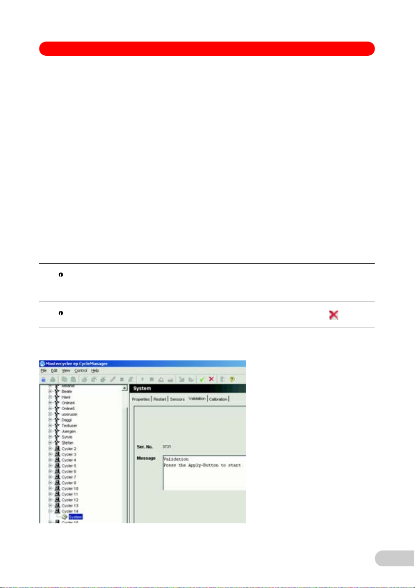
5.1.4 Verifying the Mastercycler pro/ep using the CycleManager pro
Prerequisites
• The Mastercycler is switched on.
• The Measuring device with the temperature sensor is connected to the computer and
switched on.
Hint!
All other functions of the CycleManager pro/proXL are deactivated during the
verification.
Hint!
The current verification can be interrupted at any time using the icon.
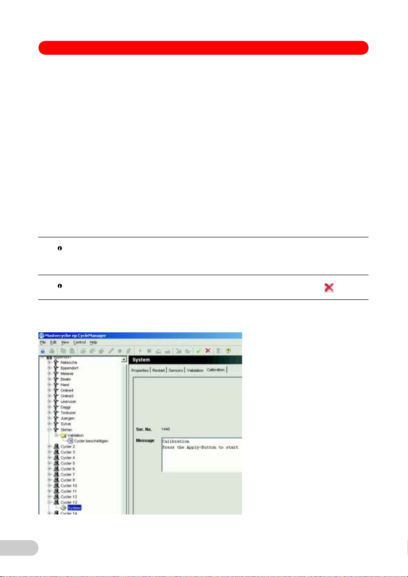
1. Start the CycleManager pro/proXL.
2. Log in as User or Administrator.
23
Page 24

Temperature Verification System USB – Single-channel — Operating manual
3. In the navigation tree, open the node of the cycler to be verified.
4. Select the System menu item.
5. Select the Verification tab.
6. Start the verification using the icon.
7. Select the Temperature Verification System USB – Single-channel using the checkbox.
8. Use the icon to confirm the selection.
You will be prompted to connect the Temperature Verification System USB – Single-channel.
9. Connect the Temperature Verification System USB – Single-channel.
10. Switch on the Measuring device.
The temperature sensor will be checked by the Mastercycler.
If the certification of the temperature sensor is no longer valid, an error message will be
shown. End the verification. Arrange to have the temperature sensor certified.
11. Confirm the query on the screen using the icon.
The verification program starts and heats the heated lid to 105 °C. You will then be prompted
to insert the temperature sensor (Insert sensor in the position indicated).
12. Open the heated lid.
13. Insert the temperature sensor in the position indicated.
14. Close the heated lid.
If a motor-driven heated lid is mounted, it automatically moves to the front position during the
next step.
15. Start the measuring cycle using the icon.
The measuring procedure runs at 95 °C and then at 35 °C.Each additional measuring cycle
begins with the request to move the temperature sensor to a different position.
16. Start each new measuring cycle using the icon.
The protocol will be shown on the monitor after the verification.
17. Complete the verification procedure using the icon.
24
Page 25

Temperature Verification System USB – Single-channel — Operating manual
5.2 Adjusting the Mastercycler nexus/pro/ep
Hint!
Only users who are logged in as Administrator can adjust the Mastercycler
nexus, pro or ep.
5.2.1 Overview
The adjustment program checks the temperature accuracy of the thermoblock and adjusts the
temperature measurement in the Mastercycler.
The Mastercycler heats the thermoblock to 95 °C and then to 35 °C. In the process, the user will
be prompted to measure the temperature in 6 different block bores that are shown on the display.
The temperature measurement in the Mastercycler will be adjusted using the externally
measured values. The procedure lasts approx. 30 minutes.
The Mastercycler outputs the measuring results on the display and a printer or a USB flash drive.
The CycleManager generates a protocol of the measurement on the monitor. The protocol can be
printed or saved as a text file using the File menu.
The following Mastercyclers save the measuring results on a MultiMediaCard:
• Mastercycler ep
• Mastercycler pro
The following Mastercyclers save the measuring results on a USB stick:
• Mastercycler pro
• Mastercycler nexus
Then, an adjustment is always confirmed by a verification.
5.2.2 Adjusting the Mastercycler nexus and Mastercycler pro
Prerequisites
• The Mastercycler is switched on.
• The Measuring device with the temperature sensor is connected and switched on.
Hint!
The Mastercycler nexus flat cannot be adjusted using the Temperature
Verification System USB – Single-channel.
Hint!
All Mastercycler nexus that are connected to each other must be in "Idle"
state. This also applies to all Mastercycler pro devices that are connected to a
control panel. No programs may be running.
Hint!
You must be logged in as administrator (_admin) if the PIN option is
activated.
Hint!
The current adjustment can be interrupted at any time using the Exit softkey.
25
Page 26

Temperature Verification System USB – Single-channel — Operating manual
1. Log in as Administrator.
2. Select the System menu item under the cycler node.
3. Press the Adjustment softkey.
The adjustment program starts and heats the heated lid to 105 °C. You will then be
prompted to insert the temperature sensor (Insert sensor in the position indicated).
4. Open the heated lid.
5. Insert the temperature sensor in the bore at the displayed position.
6. Close the heated lid.
7. Start the measuring cycle using the Enter key.
The measuring procedure runs at 95 °C and then at 35 °C.
Each additional measuring cycle begins with the request to insert the temperature sensor in
a different bore. The position will be shown on the display.
8. Repeat steps 3 to 5.
9. Start each new measuring cycle using the OK softkey.
The protocol will be shown on the display after the adjustment.
10. Check the adjustment via a subsequent verification (see Verifying the Mastercycler nexus
and Mastercycler pro on p. 20).
11. Press the Exit softkey.
The Cycler System Level window will be shown.
26
Page 27

Temperature Verification System USB – Single-channel — Operating manual
5.2.3 Adjusting the Mastercycler ep
Prerequisites
• The Mastercycler is switched on.
• The Measuring device is connected to the temperature sensor and switched on.
1. Log in as Administrator.
2. Select the System menu item under the cycler node.
3. Press the Adjustment softkey.
A note on the Temperature Verification System USB – Single-channel will be shown.
4. Confirm the note with the OK softkey.
You will be asked if you would like to use the Temperature Verification System USB –
Single-channel.
5. Answer the question using the Yes softkey.
You will be prompted to connect the Temperature Verification System USB – Single-channel.
6. Connect and switch on the Temperature Verification System USB – Single-channel.
The connection of the Temperature Verification System USB – Single-channel to the
Mastercycler devices is described in the installation chapter.
7. Confirm the request with the OK softkey.
The adjustment program starts and heats the heated lid to 105 °C. You will then be
prompted to open the lid.
8. Open the heated lid.
9. Confirm the request with the OK softkey.
You will be prompted to insert the temperature sensor (Insert sensor in the position
indicated).
10. Insert the temperature sensor in the position indicated.
11. Confirm the request with the OK softkey.
You will be prompted to close the heated lid.
12. Close the heated lid.
13. Confirm the request with the OK softkey.
The measuring cycle begins by tempering the thermoblock to 95 °C and 35 °C.
27
Page 28
Temperature Verification System USB – Single-channel — Operating manual
14. After each temperature control, read the temperature value of the measuring device and
enter it in the control panel twice.
Each additional measuring cycle begins with the request to insert the temperature sensor in
a different bore. The position will be shown on the display.
15. Repeat steps 8 to 14.
The protocol will be shown on the display after the adjustment.
The StoreMMC softkey is used to save the protocol.
The Print softkey is used to print the protocol.
16. Press the Exit softkey.
The Cycler System Level window will be shown.
5.2.4 Adjusting the Mastercycler pro/ep using the CycleManager pro
Prerequisites
• The Mastercycler is switched on.
• The Measuring device with the temperature sensor is connected to the computer and
switched on.
Hint!
All other functions of the CycleManager pro/proXL are deactivated during the
adjustment.
Hint!
The current adjustment can be interrupted at any time using the icon.
1. Start the CycleManager pro/proXL.
2. Log in as Administrator.
28
Page 29

Temperature Verification System USB – Single-channel — Operating manual
3. In the navigation tree, open the node of the cycler to be adjusted.
4. Select the System menu item.
5. Select the Adjustment tab.
6. Start the adjustment using the icon.
7. Select the Temperature Verification System USB – Single-channel using the checkbox.
8. Use the icon to confirm the selection.
You will be prompted to connect the Temperature Verification System USB – Single-channel.
9. Connect the Temperature Verification System USB – Single-channel.
10. Switch on the Measuring device.
The temperature sensor will be checked by the Mastercycler.
If the certification of the temperature sensor is no longer valid, an error message will be
shown. End the adjustment. Arrange to have the temperature sensor certified.
11. Confirm the query on the screen using the icon.
The adjustment program starts and heats the heated lid to 105 °C. You will then be
prompted to insert the temperature sensor (Insert sensor in the position indicated).
12. Open the heated lid.
13. Insert the temperature sensor in the position indicated.
14. Close the heated lid.
If a motor-driven heated lid is mounted, it automatically moves to the front position during the
next step.
15. Start the first measuring cycle using the icon.
The measuring procedure runs at 95 °C and then at 35 °C.Each additional measuring cycle
begins with the request to move the temperature sensor to a different position.
16. Repeat steps 13 to 16.
17. Start each new measuring cycle using the icon.
The protocol will be shown on the monitor after the adjustment.
18. Complete the adjustment procedure using the icon.
29
Page 30

Temperature Verification System USB – Single-channel — Operating manual
5.3 Verifying the Thermomixer and ThermoStat
Prerequisites
• The Thermomixer or ThermoStat is switched on.
• The Measuring device with the temperature sensor is switched on.
Hint!
Hint!
The Temperature sensor 1,5 mL is used to verify the following devices:
Do not verify the thermomixer during mixing.
The temperature values of the Thermomixer or ThermoStat are not
automatically compared to the temperature values of the measuring device.
All values must be noted and manually evaluated after the measurement.
• Thermomixer comfort
• Thermomixer compact
• ThermoStat plus
The Temperature sensor 384 Well is used to verify the following devices:
• ThermoMixer C
• ThermoMixer F1.5
• ThermoMixer FP
• ThermoStat C
They are referred to as "device" in the following text.
Abb. 1:Sensor position (stan dard bore) on the ThermoMixer and ThermoStat
Fig. 1: Sensor position (standard bore) on the ThermoMixer and ThermoStat
1. Insert the Temperature sensor 384 Well in the standard bore of the thermoblock (see
illustration). Insert the Temperature sensor 1,5 mL in the bore at position 15.
Position 15 is located in the 3rd row from the top and the 3rd column from the left.
2. Set a temperature of 37 °C on the device.
The thermoblock will be heated.
3. After the display shows 37 °C, wait 5 minutes.
4. Note the temperature value displayed by the measuring device.
5. Calculate and note the difference to the temperature value on the device display.
30
Page 31

Temperature Verification System USB – Single-channel — Operating manual
6. Set a higher temperature on the device.
The temperature is 75 °C on the ThermoStat and 90 °C on the Thermomixer.
7. Wait about 5 minutes after the display indicates that the set temperature has been reached.
8. Note the temperature displayed on the measuring device.
9. Calculate and note the difference to the temperature value on the device display.
10. Compare the noted temperature differences to the maximum permissible errors.
A table with several test temperatures and maximum permissible errors can be found in the
technical data. Additional data can be found in the device operating manual.
Contact your local service partner if the temperature differences are outside of the maximum
permissible errors.
6 Troubleshooting
6 Troubleshooting
6.1 General errors
6.1.1 Troubleshooting for the Measuring device
Troubleshooting, definitions and remedies can be found in the Operating manual of the
measuring device.
6.1.2 Troubleshooting for the Mastercyclers
Troubleshooting by the user
1. Switch off the device.
2. Switch the device back on after 10 seconds.
Many errors can be remedied by this step.
If the error occurs again, perform the following steps.
Troubleshooting via the local service organization
3. Note the error code and corresponding text.
4. Note the software version of the Mastercycler.
5. Note the software version of the control panel, if available.
6. Notify the local service organization.
31
Page 32

Temperature Verification System USB – Single-channel — Operating manual
7 Transport, storage and disposal
7 Transport, storage and disposal
7.1 Packing
WARNING!
WARNING! Risk to health from contaminated device
1. Observe the information in the decontamination certificate, You find it as
a PDF file on our website (www.eppendorf.com/decontamination
).
2. Decontaminate all the parts you would like to dispatch.
3. Include the fully completed decontamination certificate in the package.
Hint!
A decontamination certificate must be included when the system is sent to
Eppendorf for recertification or repair.
Proceed as follows to pack the Temperature Verification System USB – Single-channel for
storage or transportation.
1. necessary, decontaminate Temperature sensor or disinfect (see p. 34) the (see p. 33).
2. Pack the system, and all assemblies, in the supplied transport case.
The storage conditions are listed in the Measuring device operating manual.
7.2 Disposal
In case the product is to be disposed of, the relevant legal regulations are to be observed.
Information on the disposal of electrical and electronic devices in the European
Community:
Within the European Community, the disposal of electrical devices is regulated by national
regulations based on EU Directive 2002/96/EC pertaining to waste electrical and electronic
equipment (WEEE).
According to these regulations, any devices supplied after August 13, 2005, in the
business-to-business sphere, to which this product is assigned, may no longer be disposed of in
municipal or domestic waste. To document this, they have been marked with the following
identification:
Do not dispose of batteries together with domestic waste. Dispose of batteries in accordance with
local, legal regulations.
Because disposal regulations may differ from one country to another within the EU, please
contact your supplier if necessary.
32
Page 33

Temperature Verification System USB – Single-channel — Operating manual
8 Maintenance
8 Maintenance
8.1 Servicing the Measuring device
A description of the measuring device service can be found in the Measuring device operating
manual.
8.2 Servicing the Temperature sensor
Hint!
Do not use organic solvents such as phenol, chloroform or acetone.
The Temperature sensor does not require regular servicing.
Follow these steps to remove contamination on the Temperature sensor:
1. Switch off the Measuring device.
2. Clean the Temperature sensor with a mild soap solution or lint-free cloth.
3. Thoroughly rinse it using distilled water.
8.3 Removing oil from the thermoblock
1. Switch off the device.
2. Let the thermoblock cool off.
3. Remove oil from the bores.
Use a pipette to do so.
4. Rinse out the bores 4 times using 20 μL alcohol.
5. Remove oil on the thermoblock
For this, use a towel that has been moistened with alcohol.
80% ethanol is recommended as cleaning agent.
8.4 Disinfection/Decontamination
NOTICE!
NOTICE! Damage from UV and other high-energy radiation.
Do not use UV, beta, gamma, or any other high-energy radiation for
disinfecting.
Avoid storage in areas with strong UV radiation
NOTICE!
NOTICE! Damage to the device due to autoclaving.
Do not autoclave any of the Temperature Verification System USB –
Single-channel assemblies.
Auxiliary aids
• Lint-free cloth
• Disinfectant
33
Page 34

Temperature Verification System USB – Single-channel — Operating manual
1. Switch off the Temperature Verification System USB – Single-channel and remove it from the
mains/power supply.
2. Let the Temperature sensor cool off.
3. Select a disinfection method that complies with the legal requirements and regulations in
place for your range of application.
4. Spray the Temperature sensor with a disinfectant. After the exposure time of the disinfectant
has elapsed, wipe off the sensor using a damp, lint-free cloth.
8.5 Decontamination before shipment
If you are shipping the device to the authorized Technical Service for repairs or to your authorized
dealer for disposal please note the following:
WARNING!
WARNING! Risk to health from contaminated device
1. Observe the information in the decontamination certificate, You find it as
a PDF file on our website (www.eppendorf.com/decontamination
2. Decontaminate all the parts you would like to dispatch.
3. Include the fully completed decontamination certificate in the package.
9 Technical data
9 Technical data
9.1 Temperature Verification System USB – Single-channel
The technical data can be found in the operating manual of the measuring device.
9.2 Mastercycler, Thermomixer and ThermoStat
The technical data is available in the operating manual of the devices you are verifying or
adjusting.
9.3 Maximum permissible errors and accuracy
9.3.1 Temperature Verification System USB – Single-channel
Temperature Verification System USB
– Single-channel
Measuring device with grip and sensor 35 °C – 95 °C ±0,3 K
Measuring range Accuracy
).
34
Page 35

Temperature Verification System USB – Single-channel — Operating manual
9.3.2 Mastercycler
Mastercycler family Temperature Error limits
Mastercycler nexus 35 °C ±0,6 K
95 °C ±1,0 K
Mastercycler ep 35 °C ±0,6 K
95 °C ±1,0 K
Mastercycler pro 35 °C ±0,6 K
95 °C ±1,0 K
9.3.3 Thermomixer and ThermoStat
Temperature Thermomixer
comfort
0 °C ——— ——— ±1,0 K
10 °C below RT ±2,0 K ——— ———
37 °C ±0,5 K ±1,0 K ±0,5 K
56 °C ±2,0 K ±2,0 K ±1,0 K
75 °C ±2,0 K ±2,0 K ±1,0 K
Thermomixer
compact
ThermoStat plus
90 °C ±2,0 K ±2,0 K ±1,0 K
RT = room temperature
9.3.4 ThermoMixer C, ThermoMixer F1.5, ThermoMixer FP and ThermoStat C
Temperature Error limits
20 °C-45 °C ±1,0 K
<20 °C and >45 °C ±1,0 K
35
Page 36

Temperature Verification System USB – Single-channel — Operating manual
10 Ordering information
10 Ordering information
Order no.
Description
(international)
0056 000.003 Temperature Verification System USB - Single channel
For Mastercycler nexus, Mastercycler pro und Mastercycler ep,
Thermomixer, ThermoStat
Temperature sensor
for Temperature Verification System USB - Single channel
0056 001.000
0056 002.006
0056 003.002
96 Well
384 Well
1,5 mL
36
Page 37

Temperature Verification System USB – Single-channel — Operating manual
Index
Index
A
Accuracy .................................................... 34
Adjustment
Mastercycler ep .................................... 27
Mastercycler pro................................... 25
Mastercycler with CycleManager pro28, 28
Mastercyclernexus............................... 25
C
Certificate
Temperature Verification System USB... 9
Connection
Mastercycler ep .................................... 16
Mastercycler ep 384 ............................. 16
Mastercycler pro................................... 15
Mastercycler pro 384............................ 16
Mastercycler with CycleManager pro ...18
Mastercyclernexus............................... 14
D
Decontamination......................................... 34
Delivery package
Temperature sensor 1,5mL ...................7
Temperature sensor 384 Well ................7
Temperature sensor 96 Well ..................7
Temperature Verification System USB7, 7
Disinfection
Temperature sensor .............................34
Disposal...................................................... 32
E
Error limits .................................................. 34
F
Filling the measuring positions with oil
Mastercycler ep 384 ............................. 17
Mastercycler pro 384............................ 17
I
Inserting spacers
Mastercycler ep 384 ............................. 17
Mastercycler pro 384............................ 17
Inserting the temperature sensor
Mastercycler ep 384 ............................. 17
Mastercycler pro 384............................ 17
Installation
Mastercycler ep 384............................. 16
Mastercycler pro 384 ........................... 16
Intended use .............................................. 10
M
Mastercycler ep
Adjustment........................................... 27
Adjustment with the CycleManager pro 28
Connection........................................... 16
Technical data ...................................... 34
Troubleshooting ................................... 31
Verification ........................................... 22
Verification with CycleManager pro...... 23
Mastercycler ep 384
Connection........................................... 16
Filling the measuring positions with oil 17
Inserting spacers ................................. 17
Inserting the temperature sensor......... 17
Installation............................................ 16
Positioning the silicone mat ................ 18
Technical data ...................................... 34
Troubleshooting ................................... 31
Mastercycler pro
Adjustment........................................... 25
Adjustment with the CycleManager pro 28
Connection........................................... 15
Technical data ...................................... 34
Troubleshooting ................................... 31
Verification ........................................... 20
Verification with CycleManager pro...... 23
Mastercycler pro 384
Connection........................................... 16
Filling the measuring positions with oil 17
Inserting spacers ................................. 17
Inserting the temperature sensor......... 17
Installation............................................ 16
Positioning the silicone mat ................ 18
Technical data ...................................... 34
Troubleshooting ................................... 31
Mastercycler with CycleManager pro
Connection........................................... 18
Mastercyclernexus
Adjustment........................................... 25
Connection........................................... 14
Technical data ...................................... 34
Troubleshooting ................................... 31
Verification ........................................... 20
Measuring device
Service................................................. 33
Technical data ...................................... 34
37
Page 38

Temperature Verification System USB – Single-channel — Operating manual
Troubleshooting.................................... 31
O
Ordering information................................... 36
P
Packing....................................................... 32
Positioning the silicone mat
Mastercycler ep 384 ............................. 18
Mastercycler pro 384............................ 18
Product description
Temperature sensor 1,5mL ...................9
Temperature sensor 384 Well ................9
Temperature sensor 96 Well ..................8
R
Rechargeable battery
Initial charging ...................................... 13
Removing oil
Thermoblock ........................................ 33
S
Service
Measuring device ................................ 33
Temperature sensor .............................33
T
Technical data
Mastercycler ep .................................... 34
Mastercycler ep 384 ............................. 34
Mastercycler pro................................... 34
Mastercycler pro 384............................ 34
Mastercyclernexus............................... 34
Measuring device ................................ 34
Thermomixer ........................................ 34
Thermostat ........................................... 34
Temperature sensor
Disinfection........................................... 34
Service .................................................33
Temperature sensor 1,5mL
Delivery package.................................... 7
Product description................................. 9
Temperature sensor 384 Well
Delivery package.................................... 7
Product description................................. 9
Temperature sensor 96 Well
Delivery package.................................... 7
Product description................................. 8
Temperature Verification System USB
Certificate............................................... 9
Delivery package ............................... 7, 7
Properties .............................................. 7
Thermoblock
Removing oil ........................................ 33
Thermomixer
Technical data ...................................... 34
Verification ........................................... 30
ThermoStat
Verification ........................................... 30
Troubleshooting
Mastercycler ep.................................... 31
Mastercycler ep 384............................. 31
Mastercycler pro .................................. 31
Mastercycler pro 384 ........................... 31
Mastercyclernexus .............................. 31
Measuring device ................................ 31
V
Verification
Mastercycler ep.................................... 22
Mastercycler pro .................................. 20
Mastercycler with CycleManager pro23, 23
Mastercyclernexus .............................. 20
Thermomixer........................................ 30
ThermoStat .......................................... 30
38
Page 39

Temperature Verification System USB – Single-channel — Operating manual
39
Page 40

Your local distributor: www.eppendor f.com/worldwide
Eppendorf AG · 22331 Hamburg · Germany · Tel: +49 40 53801-0 · Fax: +49 40 538 01-556 · E-mail: eppendorf@eppendorf.com
Eppendorf North America, Inc. · 102 Motor Parkway · Hauppauge, N.Y. 11788-5178 · USA
Tel: +1 516 334 7500 · Toll free phone: +1 800-645-3050 · Fax: +1 516 334 7506 · E-mail: info@eppendorf.com
Application Support Europe: Tel: +49 1803 666 789 (Preis je nach Tarif im Ausland; 9 ct/min aus dem dt. Festnetz; Mobilfunkhöchstpreis 42 ct/min)
support@eppendorf.com
North America: Tel: +1 800 645 3050 · E-mail: techserv@eppendorf.com
Asia Pacific: Tel: +60 3 8023 6869 · E-mail: support_asiapacific@eppendorf.com
 Loading...